SERIES PROFESSI ONAL - Bush Hog€¦ · The care you give your Bush Hog mower will greatly...
34
©2010 Alamo Group Inc. $0.00 Published 04/11 Part No. 50045565 OPERATOR’S MANUAL BUSH HOG ® 2501 Griffin Ave. Selma, AL 36703 334-874-2700 www.bushhog.com Zero Turn Riding Mower This Operator's Manual is an integral part of the safe operation of this machine and must be maintained with the unit at all times. READ, UNDERSTAND, and FOLLOW the Safety and Operation Instructions contained in this manual before operating the equipment. C01- Cover PROFESSIONAL SERIES
Transcript of SERIES PROFESSI ONAL - Bush Hog€¦ · The care you give your Bush Hog mower will greatly...

©2010 Alamo Group Inc. $0.00
Published 04/11 Part No. 50045565
OPERATOR’S MANUAL
BUSH HOG®
2501 Griffin Ave. Selma, AL 36703334-874-2700www.bushhog.com
Zero Turn Riding Mower
This Operator's Manual is an integral part of the safe operation of this machine and mustbe maintained with the unit at all times. READ, UNDERSTAND, and FOLLOW the Safetyand Operation Instructions contained in this manual before operating the equipment. C01-Cover
PROFESSIONALSERIES

CONGRATULATIONS!You have invested in the best mower of its type on the market today.
The care you give your Bush Hog mower will greatly determine your satisfactionwith its performance and its service life. We urge a careful study of this manual to provideyou with a thorough understanding of your new mower before operating, as well assuggestions for operation and maintenance.
If your manual should become lost or destroyed, Bush Hog will be glad to provide you witha new copy. Order from Bush Hog, P. O. Box 1039, Selma, Alabama 36702-1039. Most ofour manuals can also be downloaded from our website at www.bushhog.com.
As an authorized Bush Hog dealer, we stock genuine Bush Hog parts which aremanufactured with the same precision and skill as our original equipment. Our trainedservice personnel are well informed on methods required to service Bush Hog equipment,and are ready and able to help you.
Should you require additional information or assistance, please contact us.
YOUR AUTHORIZEDBUSH HOG DEALER
BECAUSE BUSH HOG MAINTAINS AN ONGOINGPROGRAM OF PRODUCT IMPROVEMENT, WERESERVE THE RIGHT TO MAKE IMPROVEMENTS INDESIGN OR CHANGES IN SPECIFICATIONS WITH-OUT INCURRING ANY OBLIGATION TO INSTALLTHEM ON UNITS PREVIOUSLY SOLD.
BECAUSE OF THE POSSIBILITY THAT SOMEPHOTOGRAPHS IN THIS MANUAL WERE TAKEN OFPROTOTYPE MODELS, PRODUCTION MODELS MAYVARY IN SOME DETAIL. IN ADDITION, SOMEPHOTOGRAPHS MAY SHOW SHIELDS REMOVEDFOR PURPOSES OF CLARITY. NEVER OPERATETHIS IMPLEMENT WITHOUT ALL SHIELDS IN PLACE.
PROFESSIONAL SERIESZERO TURN RIDING MOWER
TABLE OF CONTENTSSECTION PAGE
Warranty. . . . . . . . . . . . . . . . . . . . . . . . . . 2Dealer Preparation Check List . . . . . . . . . 3Safety Alert Symbols . . . . . . . . . . . . . . . . 4Safety Precautions . . . . . . . . . . . . . . . . . . 5Federal Laws and Regulations. . . . . . . . . 8
I INTRODUCTION AND DESCRIPTION . . 9Introduction. . . . . . . . . . . . . . . . . . . . . . . . 9Description . . . . . . . . . . . . . . . . . . . . . . . . 9Specifications . . . . . . . . . . . . . . . . . . . . . 10
II OPERATION . . . . . . . . . . . . . . . . . . . . . 11General Safety . . . . . . . . . . . . . . . . . . . . 11Pre-Operation Checklist . . . . . . . . . . . . . 11Operation . . . . . . . . . . . . . . . . . . . . . . . . 12Mowing Recommendations . . . . . . . . . . 14
III MAINTENANCE . . . . . . . . . . . . . . . . . . . 15Maintenance Schedule. . . . . . . . . . . . . . 15Engine . . . . . . . . . . . . . . . . . . . . . . . . . . 16
SECTION PAGEBattery . . . . . . . . . . . . . . . . . . . . . . . . . .16Tires . . . . . . . . . . . . . . . . . . . . . . . . . . . .16Mower Blades . . . . . . . . . . . . . . . . . . . . .16Motion Control Adjustment . . . . . . . . . . .17Drive Adjustments . . . . . . . . . . . . . . . . .17Test Drive Operations . . . . . . . . . . . . . .17Leveling The Deck . . . . . . . . . . . . . . . . .18Counterbalance Spring . . . . . . . . . . . . . .18Deck Belt Adjustment . . . . . . . . . . . . . .18Deck Belt Replacement . . . . . . . . . . . . .18Start Up Maintenance . . . . . . . . . . . . . . .19Troubleshooting . . . . . . . . . . . . . . . . . . .20
IV ASSEMBLY . . . . . . . . . . . . . . . . . . . . . .21Wiring Schematics . . . . . . . . . . . . . . . . .22Safety Decals . . . . . . . . . . . . . . . . . . . . .25Torque Specifications . . . . . . . . . . . . . . .27Optional Equipment List . . . . . . . . . . . . .28Slope Angle Guide . . . . . . . . . . . . . . . . .29
1
RETAIL CUSTOMER’S RESPONSIBILITYUNDER THE BUSH HOG WARRANTY
It is the Retail Customer and/or Operator’s responsibility to read the Operator’s Manual, to op-erate, lubricate, maintain and store the product in accordance with all instructions and safetyprocedures. Failure of the operator to read the Operator’s Manual is a misuse of this equipment.
It is the Retail Customer and/or Operator’s responsibility to inspect the product and to have anypart(s) repaired or replaced when continued operation would cause damage or excessive wearto other parts or cause a safety hazard.
It is the Retail Customer’s responsibility to deliver the product to the authorized Bush HogDealer, from whom he purchased it, for service or replacement of defective parts which are cov-ered by warranty. Repairs to be submitted for warranty consideration must be made withinforty-five (45) days of failure.
It is the Retail Customer’s responsibility for any cost incurred by the Dealer for traveling to orhauling of the product for the purpose of performing a warranty obligation or inspection.

PROFESSIONAL SERIES (PZ) ZERO TURN RIDING MOWER LIMITED WARRANTY●●●●●●●●●●●●●●●●●●●●●●●●●●●●●●●●●●●●●●●●●●
Bush Hog warrants to the original purchaser of this new Zero Turn Riding Mower, purchased from an authorized Bush Hogdealer, that the equipment be free from defects in material and workmanship as follows (see dealer for complete details):
• for a period of three (3) years from the date of the retail sale to the original purchaser (the “Three Year Warranty”),but only as to the drive train, electromagnetic clutch, deck and cutter spindles; and
• for the entire length of ownership by the original purchaser (“Limited Lifetime Warranty”), but only as to thedeck weldment which results in the deck not performing its function, in the sole opinion of Bush Hog. Malfunctionscaused by corrosion are not covered by the Limited Lifetime Warranty.
For the Three Year Warranty and the Limited Lifetime Warranty, the obligation of Bush Hog to the purchaser is lim-ited to the repair or replacement of defective parts, at the sole option of Bush Hog. NOTE: The Three Year Warrantycovers parts and labor for the first two years and parts only during the third year.
The Three Year Warranty and the Limited Lifetime Warranty are referred to collectively in this document as the “limited warranty”.
Replacement or repair parts installed in the equipment covered by this limited warranty are warranted for ninety (90) days fromthe date of purchase of such part or to the expiration of the applicable new equipment warranty period, whichever occurs later.Warranted parts shall be provided at no cost to the user at an authorized Bush Hog dealer during regular working hours. BushHog reserves the right to inspect any equipment or parts which are claimed to have been defective in material or workman-ship.
DISCLAIMER OF IMPLIED WARRANTIES & CONSEQUENTIAL DAMAGESBush Hog’s obligation under this limited warranty, to the extent allowed by law, is in lieu of all warranties, implied or
expressed, INCLUDING IMPLIED WARRANTIES OF MERCHANTABILITY AND FITNESS FOR A PARTICULAR PURPOSEand any liability for incidental and consequential damages with respect to the sale or use of the items warranted. Such inci-dental and consequential damages shall include but not be limited to: transportation charges other than normal freight charges;cost of installation other than cost approved by Bush Hog; duty; taxes; charges for normal service or adjustment; loss of cropsor any other loss of income; rental of substitute equipment, expenses due to loss, damage, detention or delay in the deliveryof equipment or parts resulting from acts beyond the control of Bush Hog.
THIS LIMITED WARRANTY SHALL NOT APPLY:1. To transportation to and from dealership or service calls made by dealers, ie, driving time, towing, pickup and delivery.
2. To vendor items which carry their own warranties, such as engines, batteries, tires, and tubes.
3. If the unit has been subjected to misapplication, abuse, misuse, negligence, fire or other accident.
4. If parts not made or supplied by Bush Hog have been used in connection with the unit, if, in the sole judgement of BushHog such use affects its performance, stability or reliability.
5. If the unit has been altered or repaired outside of an authorized Bush Hog dealership in a manner which, in the solejudgement of Bush Hog, affects its performance, stability or reliability.
6. To normal maintenance service and normal replacement items such as gearbox lubricant, hydraulic fluid, worn blades,or to normal deterioration of such things as belts and exterior finish due to use or exposure.
7. To expendable or wear items such as blades, chains, sprockets, belts, springs and any other items that in the company’ssole judgement is a wear item.
NO EMPLOYEE OR REPRESENTATIVE OF BUSH HOG IS AUTHORIZED TO CHANGE THIS LIMITED WARRANTY INANY WAY OR GRANT ANY OTHER WARRANTY UNLESS SUCH CHANGE IS MADE IN WRITING AND SIGNED BY BUSHHOG’S SERVICE MANAGER, 2501 GRIFFIN AVE., SELMA, AL. 36703
●●●●●●●●●●●●●●●●●●●●●●●●●●●●●●●●●●●●●●●●●●Record the model number, serial number and datepurchased. This information will be helpful to yourdealer if parts or service are required.
MAKE CERTAIN THE WARRANTY REGISTRATIONCARD HAS BEEN FILED WITH BUSH HOG2501 GRIFFIN AVE., SELMA, AL. 36703
MODEL NUMBER
SERIAL NUMBER
DATE OF RETAIL SALE
2

DEALER PREPARATION CHECK LISTPROFESSIONAL ZERO TURN RIDING MOWER
BEFORE DELIVERING MACHINE — The following check list should be completed.Use the Operator’s Manual as a guide.
r 1. Engine has been serviced.
r 2. Battery fluid level is checked.
r 3. Low oil pressure warning buzzer checked for operation.
r 4. Operator interlock switches checked for operation.
r 5. Assembly completed.
r 6. All fittings lubricated.
r 7. Hydraulic Reservoir filled with oil.
r 8. All shields in place and in good condition.
r 9. Roll-over protective structure is installed and retractable seat belt functionsproperly.
r 10. All fasteners torqued to specifications given in Torque Chart.r 11. All decals in place and readable. (See decal page.)
r 12. Overall condition good. (i.e. paint, welds)
r 13. Parking brake checked and adjusted, if necessary.
r 14. Steering checked and adjusted, if necessary.
r 15. Check tire pressure.
r 16. Operators manual has been delivered to owner and he has been instructedon the safe and proper use of the cutter.
Dealer’s Signature
Purchaser’s Signature
THIS CHECKLIST TO REMAIN IN OWNER’S MANUALIt is the responsibility of the dealer to complete the procedures listed
above before delivery of this implement to the customer.
WARRANTY REGISTRATION AND DELIVERY REPORT
It is the responsibility of the Dealer to do the following:• Complete the Warranty Registration and Delivery Report Online
3

Safety Alert SymbolThis Safety Alert Symbol means: “ATTENTION! BECOME ALERT!YOUR SAFETY IS INVOLVED!”
This symbol is used to call attention to safetyprecautions that should be followed by the oper-ator to avoid accidents. When you see this sym-bol, carefully read the message that follows andheed its advice. Failure to comply with safety pre-cautions could result in death or serious bodilyinjury.
Safety Signs Signal WordsThe signal words DANGER, WARNING, AND CAUTION are used on the equipment safety signs. These wordsare intended to alert the viewer to the existence and the degree of hazard seriousness.
This signal word indicates a potentially hazardous situation which,if not avoided, will result in death or serious injury.
This signal word indicates a potentially hazardous situation which,if not avoided, could result in death or serious injury
It may also be used to alert against unsafe practices.
Black letters on ORANGE
White letters on Red
This signal word indicates a potentially hazardous situation existwhich, if not avoided, may result in minor or moderate injury.
It may also be used to alert against unsafe practices.
Black letters on YELLOW
4

IMPORTANT SAFETY PRECAUTIONSThis symbol is used to call attention to safe-ty precautions that should be followed bythe operator to avoid accidents. When yousee this symbol, carefully read the messagethat follows and heed its advice. Failure tocomply with safety precautions could resultin serious bodily injury.
In addition to the design and configuration of equipment, hazard control and accident prevention aredependent upon the awareness, concern, prudence and proper training of personnel in the operation,transport, maintenance and storage of equipment. Lack of attention to safety can result in accident, personal injury, reduction of efficiency and worst of all—loss of life. Watch for safety hazards and correct deficien-cies promptly. Use the following safety precautions as a general guide to safe operations when using thismachine. Additional safety precautions are used throughout this manual for specific operating and maintenance procedures. Read this manual and review the safety precautions often until you know the limitations.
ACCIDENT PATTERNS TO AVOID1. CONTACT WITH THE ROTATING BLADE - This accident usually happens when the operator is clear-
ing the discharge chute of grass, (especially when the grass is wet), or when the operator adjusts themachine without turning it off and waiting for the blades to completely stop.
2. PROPELLED OBJECTS - Sticks, rocks, wires, and other objects can be propelled out through the dis-charge chute or from under the mower housing. Bystanders are particularly vulnerable.
3. GRASS DISCHARGE CHUTE - The mower shall not be operated without the grass discharge chutein its lowered position.
4. OVERTURNING - This happens when riding mowers are used on steep slopes, embankments or hills.The operator in these cases can come in contact with blades or sustain injuries during a fall.
5. MOWER RUNNING OVER THE VICTIM - This usually happens when a riding mower is driven inreverse. The accident victims are most often young children whom, unseen by the operator of themower, were in the area being mowed.
WE SHARE YOUR DESIRE TO PROTECT YOURSELF, YOUR FAMILY, YOUR FRIENDS AND YOURNEIGHBORS FROM ACCIDENTAL INJURY. OBSERVING AND ENFORCING THE FOLLOWING GUIDELINES WILL HELP TO INSURE THE SAFETY OF EVERYONE.
SAFETY INSTRUCTIONS AND RECOMMENDATIONS
1. PEOPLE WHO OPERATE, SERVICE, OR ARE OTHERWISE ASSOCIATED with the Zero Turn Riding Mowershould be trained in its proper use and warned of its dangers. Before operating, adjusting,or servicing the Zero Turn Riding Mower they should read and understand this entire manual and theengine manual.
2. AVOID CONTACT WITH MOVING PARTS. Keep hands and feet from under mowing deck and awayfrom blades at all times. Turn engine (motor) off if you must unclog the discharge chute.
3. AVOID HILLS AND SLOPES. Use EXTREME caution when mowing and/or turning on slopes as loss of tractionand/or tip-over could occur. Drive slower on slopes. DO NOT mow slopes greater than 15 degrees. Watch forditches, holes, rocks, dips and rises, which change the operating angle. Keep away from drop-offs and steepbanks. Avoid sudden starts when mowing uphill - mower may tip backwards. Loss of traction may occur goingdownhill - weight transfer to the front wheels may cause drive wheels to slip and cause loss of braking. DO NOTmow slopes when grass is wet - slippery conditions affect steering and reduce traction and braking. The operatoris responsible for safe operation on slopes.
4. DISENGAGE POWER TO MOWER BEFORE BACKING UP. Do not mow in reverse unless absolutelynecessary and then only after turning around and observing the entire area behind the mower. Go slowly.Most “running over victim” accidents occur in reverse.
5. BEGINNING OPERATORS SHOULD LEARN HOW TO STEER the Zero Turn Riding Mower beforeattempting to mow. Start with slow engine speed and drive without the blades engaged in open area untilcomfortable with the machine.
5

SAFETY CONTINUED
6. KNOW HOW TO STOP QUICKLY. Know the location and operation of every control, especially how to brake andhow to disengage the mower blades.
7. DO NOT MOVE THE CONTROL LEVERS from forward position to reverse position rapidly. The speedand/or direction of travel is affected instantly by movement of the Control Levers.
8. DO NOT ALLOW CHILDREN TO OPERATE MOWER. Do not allow others who have not had instruc-tions to operate mower. Do not operate the mower when children or others are in the area.
9. ALWAYS TURN ENGINE OFF AND REMOVE KEY before leaving mower to prevent children andinexperienced operators from starting the engine. Never leave the mower unattended with engine run-ning. Always wait for all moving parts and all sounds to stop before leaving operator’s seat. Always setthe parking brake on an unattended mower.
10. WEAR STURDY, ROUGH-SOLED WORK SHOES AND CLOSE-FITTING TROUSERS AND SHIRTS.Never operate mower in bare feet, sandals or sneakers.
11. WEAR PERSONAL PROTECTIVE EQUIPMENT such as, but not limitied to, protection for eyes, ears, feet, handsand head when operating or repairing equipment. Do not wear loose clothing or jewelry that may catch on equip-ment moving parts.
12. NEVER CARRY PASSENGERS.
13. KNOW THE AREA YOU ARE TO MOW. Watch for hidden dangers such as rocks, roots, sticks, holes,bumps, and drop-offs, etc. Before mowing, pick up all debris in area to be mowed. Sharp and hardobjects can be propelled at a high speed and can act like shrapnel. Walk through tall grass BEFOREMOWING to make sure there are no hidden dangers. Mow higher than desired in tall grass to exposeany hidden objects and/or obstacles, clean the area, and then mow to the desired height.
14. BE SURE THE AREA IS CLEAR of other people before mowing. Stop machine if anyone enters the area.
15. NEVER REFUEL A MOWER INDOORS. Allow the engine time to cool before refueling. Unseen vapors may beignited by a spark. Always clean up spilled gasoline. Never run the engine indoors in a garageor any other closed building. Allow engine to cool before storing in any enclosure. The engine exhaustand gasoline fumes are dangerous.
16. NEVER REMOVE THE FUEL CAP or add gasoline to a running or hot engine or anengine that has not been allowed to cool for several minutes after running. Always make sure the gascap is in place.
17. DO NOT SMOKE AROUND THE MOWER or the gasoline storage container. Gasoline fumes can easi-ly ignite.
18. KEEP GASOLINE IN A WELL-VENTILATED AREA away from your living quarters and in tightlycapped safety cans. Never store mower with gasoline in the tank inside a building where fumes mayreach open flame or spark.
19. DISENGAGE BLADES, STOP ENGINE, ENGAGE PARKING BRAKE AND REMOVE IGNITION KEY before anyservicing. Be sure all moving parts and all sounds have stopped. Let engine cool and disconnect the spark plugs sothe engine cannot start by accident.
20. KEEP ALL NUTS, BOLTS, AND SCREWS TIGHT to be sure equipment is in safe working condition, espe-cially blade bolts.
21. VEHICLE SHOULD BE STOPPED AND INSPECTED FOR DAMAGE after striking a foreign object andthe damage should be repaired before restarting and operating the equipment. Stop immediately andcheck for damage or loose parts if mower should start vibrating.
22. DISENGAGE BLADES BEFORE DRIVING ACROSS WALKS or projecting objects or transporting.
23. KEEP SAFETY DEVICES AND GUARDS IN PLACE. If any of the safety switches become inoperable,have them repaired immediately.
24. DO NOT STEP OR STAND ON THE MOWER HOUSING. Step or stand only on the tread areas on the deck.
25. WATCH OUT FOR TRAFFIC near roadways and when crossing roads.
26. THIS MACHINE IS NOT MEANT FOR HIGHWAY OR STREET USE. It is not a recreational vehicle and it should notbe operated as such.
27. WHEN FEASIBLE, DO NOT USE MOWER WHEN GRASS IS WET OR SLIPPERY.
28. MOW ONLY IN DAYLIGHT OR GOOD ARTIFICIAL LIGHT.
6
SAFETY CONTINUED
29. ALWAYS DISENGAGE THE MOWER BLADE CLUTCH when transporting.
30. Do not operate the mower under influence of drugs or alcohol.
31. Do not change the engine governor settings or overspeed the engine. Operating an engine at excessive speed mayincrease the hazard of personal injury.
TOWING1. Use for towing only if equipped with a Bush Hog hitch kit. Do not attach towed equipment except at the hitch point.
2. Never allow children or others in or on towed equipment.
3. On slopes, the weight of the towed equipment may cause loss of traction and loss of control.
4. Travel slowly and allow extra distance to stop.
SLOPE OPERATION
1. Use EXTREME caution when mowing and/or turning on slopes as loss of traction and/or tip-over could occur. Theoperator is responsible for safe operation.
2. See inside of the back cover to determine the approximate slope angle of the area to be mowed.
3. Use a walk behind mower and/or a hand trimmer near drop-offs, ditches, steep banks or water. This area can be dangerous.
4. Progressively greater care is needed as the slope increases.
5. Always avoid sudden starting or stopping on a slope. If tires lose traction, disengage the blades and proceed slowly down theslope.
6. Avoid sudden starts when mowing uphill. Mower may tip backwards.
7. Be aware that loss of traction may occur going downhill. Weight transfer to the front wheels may cause drive wheels toslip and cause loss of braking and steering.
8. Watch for ditches, holes, rocks, dips, and rises that change the operating angle, as rough terrain could overturn the machine.Tall grass can hide obstacles.
9. Remove or mark obstacles such as rocks, tree limbs, etc. from the ,mowing area. Tall grass can hide obstacles.
10. Use extreme care with grass catches or attachments. These can change the stability of the machine and cause loss of control.
11. Follow the manufacturer’s recommendations for counterweights to improve stability.
12.. Check carefully for overhead clearances (ie. branches, doorways, and electrical wires) before driving under objects anddo not contact them.
SLOPE ANGLE GUIDE LOCATED INSIDE REAR COVER
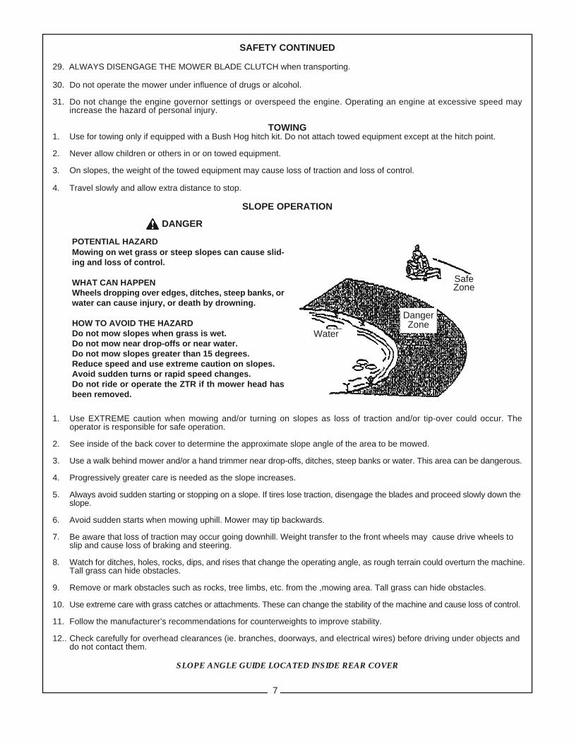
DANGER
POTENTIAL HAZARDMowing on wet grass or steep slopes can cause slid-ing and loss of control.
WHAT CAN HAPPENWheels dropping over edges, ditches, steep banks, orwater can cause injury, or death by drowning.
HOW TO AVOID THE HAZARDDo not mow slopes when grass is wet.Do not mow near drop-offs or near water.Do not mow slopes greater than 15 degrees.Reduce speed and use extreme caution on slopes.Avoid sudden turns or rapid speed changes.Do not ride or operate the ZTR if th mower head hasbeen removed.
SafeZone
Water
DangerZone
7

IMPORTANT FEDERAL LAWS AND REGULATIONS* CONCERNINGEMPLOYERS, EMPLOYEES AND OPERATIONS.
*(This section is intended to explain in broad terms the concept and effect of the following federal laws andregulations. It is not intended as a legal interpretation of the laws and should not be considered as such).
U.S. Public Law 91-596 (The Williams-Steiger Occupational and Health Act of 1970) OSHA
This Act Seeks:“...to assure so far as possible every working man and woman in the nation safe and healthful workingconditions and to preserve our human resources...”
DUTIESSec. 5 (a) Each employer—(1) shall furnish to each of his employees employment and a place of employment
which are free from recognized hazards that are causing or are likely to causedeath or serious physical harm to his employees;
(2) shall comply with occupational safety and health standards promulgated underthis Act.
(b) Each employee shall comply with occupational safety and health standardsand all rules, regulations and orders issued pursuant to this Act which areapplicable to his own actions and conduct.
OSHA RegulationsCurrent OSHA regulations state in part: “At the time of initial assignment and at least annually thereafter, theemployer shall instruct every employee in the safe operation and servicing of all equipment with which theemployee is, or will be involved.” These will include (but are not limited to) instructions to:
Keep all guards in place when the machine is in operation;
Permit no riders on equipment;
Stop engine, disconnect the power source, and wait for all machine movement to stop beforeservicing, adjusting, cleaning or unclogging the equipment, except where the machine must berunning to be properly serviced or maintained, in which case the employer shall instruct employeesas to all steps and procedures which are necessary to safely service or maintain the equipment.
Make sure everyone is clear of machinery before starting the engine, engaging power, or operatingthe machine.
Child Labor Under 16 Years OldSome regulations specify that no one under the age of 16 may operate power machinery. It is yourresponsibility to know what these regulations are in your own area or situation. (Refer to U.S. Dept. ofLabor, Employment Standard Administration, Wage & Home Division, Child Labor Bulletin #102.)
8

INTRODUCTION
We are pleased to have you as a Bush Hog customer.Your Bush Hog Zero Turn Riding Mower has beencarefully designed to give maximum service with min-imum down time. This manual is provided to give youthe necessary operating and maintenance instruc-tions for keeping your mower in top operating condi-tion. Please read this manual thoroughly. Understandwhat each control is for and how to use it. Observe allsafety precautions decaled on the machine and notedthroughout the manual for safe operation of the im-plement. If any assistance or additional information isneeded, contact your authorized Bush Hog dealer.
NOTE:All references made to right, left, front, rear, top or bot-tom is as viewed facing the direction of forward travel.
DESCRIPTION
The Zero Turn Riding Mower is intended for use onlawns and other frequently maintained areas where a
smooth, even cut is desired and superior maneuver-ability is needed. The tractor unit consists of either a25 hp Kawasaki, 26 hp Kawasaki, 27 hp Kohler, 28 hpEFI Kohler or 30 hp Kohler twin cylinder engine. Theengine has a pressurized oil lubrication system withspin-on type filter, fused electronic ignition, electric startand a 15.5 gallon fuel system with 61” and 73” decks ora 12.5 gallon fuel system with 55” decks.
Two hydrostatic pumps and two wheel motors areused for propelling and steering. The pumps are beltdriven by the engine output shaft. One lever for eachdrive controls both speed and direction. This inde-pendent control of each drive wheel coupled with con-tinuously variable speed selection gives the Zero Turnmower exceptional maneuverability.
The mower attachment is available in 55”, 61” or 73”cutting widths. The mower has three cutting bladesdriven by an electromagnetic clutch through a singleV-belt
9
SECTION IINTRODUCTION AND DESCRIPTION
CONTROLS
OPERATOR INTERLOCK SYSTEM
Your Bush Hog Zero Turn Riding Mower is equippedwith an Operator Interlock System that is designed tohelp prevent possible serious injuries. Understandingand maintaining this system is vital for safe operation.
To Start Engine:1. Blades (PTO) must be disengaged.2. Control levers in neutral (swung out).3. Parking brake set.
The Engine Will Stop If:1. The operator leaves the seat with:
a. The control levers out of neutral (swungin).
b. The blades are engaged.c. The parking brake is off.d. All of the above.
2. The park brake is on before the control leversare swung in.
DO NOT OPERATE MOWER IF SAFETYSWITCHES ARE NOT OPERATING PROPERLY.OPERATOR CONTROLS
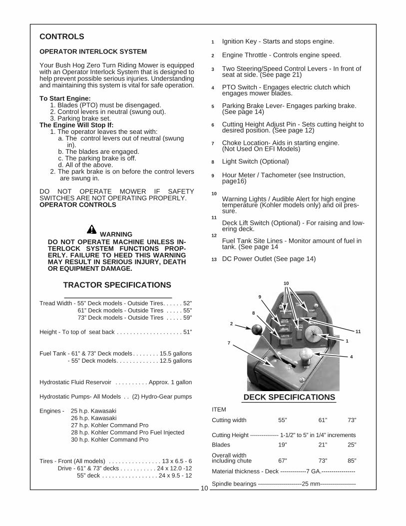
1 Ignition Key - Starts and stops engine.
2 Engine Throttle - Controls engine speed.
3 Two Steering/Speed Control Levers - In front ofseat at side. (See page 21)
4 PTO Switch - Engages electric clutch whichengages mower blades.
5 Parking Brake Lever- Engages parking brake.(See page 14)
6 Cutting Height Adjust Pin - Sets cutting height todesired position. (See page 12)
7 Choke Location- Aids in starting engine.(Not Used On EFI Models)
8 Light Switch (Optional)
9 Hour Meter / Tachometer (see Instruction,page16)
10Warning Lights / Audible Alert for high enginetemperature (Kohler models only) and oil pres-sure.
11Deck Lift Switch (Optional) - For raising and low-ering deck.
12Fuel Tank Site Lines - Monitor amount of fuel intank. (See page 14
13 DC Power Outlet (See page 14)
TRACTOR SPECIFICATIONS
Tread Width - 55” Deck models - Outside Tires. . . . . . 52”61” Deck models - Outside Tires . . . . . 55”73” Deck models - Outside Tires . . . . . 59”
Height - To top of seat back . . . . . . . . . . . . . . . . . . . . 51”
Fuel Tank - 61” & 73” Deck models . . . . . . . . 15.5 gallons- 55” Deck models. . . . . . . . . . . . . 12.5 gallons
Hydrostatic Fluid Reservoir . . . . . . . . . . Approx. 1 gallon
Hydrostatic Pumps- All Models . . (2) Hydro-Gear pumps
Engines - 25 h.p. Kawasaki26 h.p. Kawasaki27 h.p. Kohler Command Pro28 h.p. Kohler Command Pro Fuel Injected30 h.p. Kohler Command Pro
Tires - Front (All models) . . . . . . . . . . . . . . . . 13 x 6.5 - 6Drive - 61” & 73” decks . . . . . . . . . . . 24 x 12.0 -12
55” deck . . . . . . . . . . . . . . . . . 24 x 9.5 - 12
DECK SPECIFICATIONSITEM
Cutting width 55” 61” 73”
Cutting Height --------------- 1-1/2” to 5” in 1/4” increments
Blades 19” 21” 25”
Overall widthincluding chute 67” 73” 85”
Material thickness - Deck -------------7 GA.-----------------
Spindle bearings ----------------------25 mm------------------10
WARNINGDO NOT OPERATE MACHINE UNLESS IN-TERLOCK SYSTEM FUNCTIONS PROP-ERLY. FAILURE TO HEED THIS WARNINGMAY RESULT IN SERIOUS INJURY, DEATHOR EQUIPMENT DAMAGE.
10
9
4
7
2
1
11
8
SECTION IIOPERATION
GENERAL SAFETY
Only qualified people familiar with this operator’s man-ual should operate this machine. Operator shouldwear hard hat, safety glasses, and safety shoes. Avoidloose fitting clothing or jewelry. The operator shouldread, understand and practice all safety messagesshown on the caution, warning and danger decals af-fixed to the machine to avoid serious injury or death.Before beginning operation, clear work area of any ob-jects that may be picked up and thrown by mower.Check for ditches, stumps, holes or other obstaclesthat could upset power unit or damage mower. Tallgrass can hide obstacles. Always push steering leversapart, set parking brake, disengage PTO, turn off en-gine, and allow blades to come to a complete stop be-fore leaving operator’s seat. Do not operate without allshields in place and in good condition.
PRE-OPERATION CHECKLIST
1. Make sure fuel tank is full. Use regular unleadedgasoline. See engine manual for more details.
2. Make sure dirt and foreign matter are kept out offuel tank. Use a clean funnel and fuel can.
3. Do not mix oil with gasoline.
4. Do not use white, high test or premium gasoline.Do not use de-icers, carburetor cleaners or othersuch additives.
5. Check the crankcase oil level. Make sure theengine is off. The mower should be parked on alevel area. Do not overfill. (See your engine man-ual for more detailed instructions.)
6. Check the hydrostatic transmission oil level. (See“Maintenance” section of this manual.)
7. Check battery fluid level.
AVOID SERIOUS INJURY OR DEATH:GASOLINE IS EXTREMELY FLAMMABLE AND EX-PLOSIVE UNDER CERTAIN CONDITIONS.ll REFUEL IN A WELL VENTILATED AREA WITH ENGINE STOPPED.
ll DO NOT SMOKE OR ALLOW FLAMES OR SPARKS IN THE REFUELING AREA OR WHERE GASOLINE IS BEING STORED.
ll DO NOT OVERFILL FUEL TANK. AFTERREFUELING, MAKE CERTAIN THE TANK CAP IS CLOSED PROPERLY AND SECURELY.
ll BE CAREFUL NOT TO SPILL FUEL WHEN REFUELING. FUEL VAPOR OR SPILLED FUELMAY IGNITE. IF ANY FUEL IS SPILLED, MAKESURE THE AREA IS DRY BEFORE STARTINGTHE ENGINE.
ll KEEP OUT OF REACH OF CHILDREN
11
8. Inspect V-belts
9. Check tire pressure (Use low pressure gauge): Front Tires - 15 psi, Drive Tires - 15 psi
10. Make sure underside of mower deck is free ofgrass.
11. Make sure mower blades are sharp and secured tightly.
12. Clean the air intake screen on the engine ifnecessary.
13. Perform any other maintenance as it becomes necessary. (See “Maintenance” section)
14.Check low oil pressure warning buzzer for opera-tion. (It should “sound-off” whenever ignition keyis in the “on” position, but engine is not running.)
15. Check parking brake operation by disengaging hydrostatic pumps (freewheeling position), andplacing the brake lever in the “on” position. Attempt to rock tractor by hand. Both drive wheels should be locked. When the brake handle is in the “off” position, both drive wheels should turn freely.If there is a problem in either position, refer to adjustment procedure in the maintenance section.
16. Seat Adjustments: The high-back full suspensionseat has a variable rate suspension system,adjustable lumbar support and sliding seat toaccomodate different operators.
Operator Weight Adjustment Knob - Turn the knob until the indicator position closely matches yourweight to give the most comfortable ride.
Adjustable Lumbar Knob (Under left arm rest) -Turn knob clockwise or counter-clockwise to achieve desired support.
Back Angle Adjustment Knob (Under right arm rest) -Turn knob clockwise or counter-clockwise to achieve desired support.
Lever Release Seat Slides - Pull the lever outward to release the latch. Slide the seat forward or rear-ward to your most comfortable position and release the lever.
WARNINGENGINE EXHAUST GASES CONTAINPOISONOUS CARBON MONOXIDE.
ll NEVER RUN ENGINE IN A CLOSED BUILDING OR CONFINED AREA.
ll AVOID INHALING EXHAUST GASES.
WARNING
If the operator is inexperienced with the zero turnmower lever steering/speed control, he/sheshould follow these recommendations: Disengagethe mower blades. Go very slowly until thoroughlyfamiliar with the machine. Keep away from fences,buildings, and other obstructions. While becoming familiar with the machine, move the ControlLevers smoothly and slowly. Practice until operation is smooth and efficient.
10. A roll-over protection system (ROPS) is installedon your machine. Operate unit with the ROPS inthe raised and locked position and use seat belt.There is no roll-over protection when the ROPSis down. If it is necessary to lower the ROPS, donot wear seat belt. Raise the ROPS as soon asclearance permits.
11. TO DRIVE: Adjust seat forward or backward for operator comfort. Move the Control Levers to the “IN” position. Move Control Levers forward to move forward. Move levers slowly forward toincrease speed. To reverse direction, move theControl Lever on the side to which you want toturn slightly rearward of the other Control Lever. To turn on a zero radius axis, go slowly and pullone Control Lever back and push the other Control Lever forward, depending on whichdirection you wish to turn.
WARNING
AVOID SERIOUS INJURY OR DEATH:DO NOT MOVE STEERING LEVERS FROM FORWARD TO REVERSE OR REVERSE TO FORWARDPOSITION RAPIDLY. A SUDDEN CHANGE IN DIRECTION MAY CAUSE LOSS OF CONTROL AND/ORDAMAGE TO EQUIPMENT. FOR SMOOTH, SAFE OPERATION, MOVE THE CONTROL LEVERS IN A GENTLE, SLOW MOTION, ESPECIALLY ON GRADES.
12. BRAKING: To brake mower, gently moveControl Levers in the direction opposite to travel.If the parking brake is engaged with the Control Levers in the “IN” position the engine will stop.
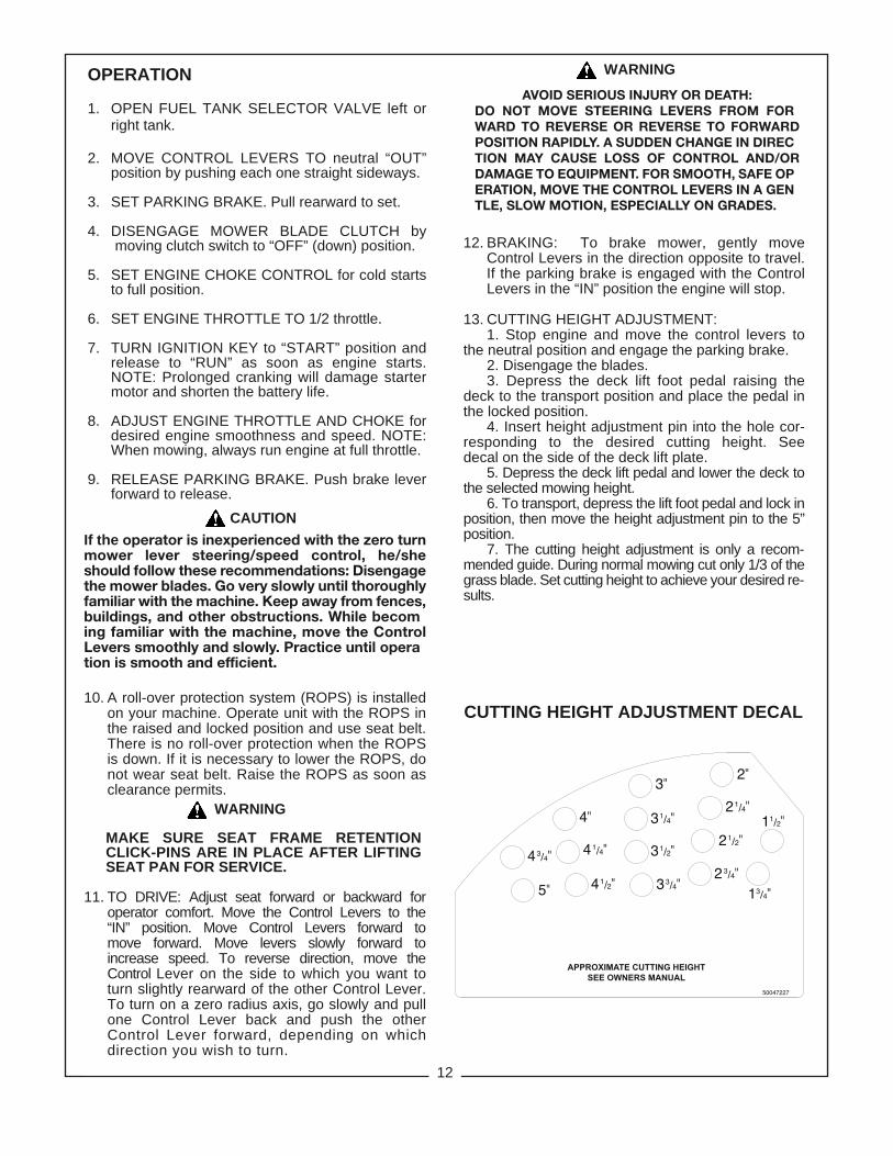
13. CUTTING HEIGHT ADJUSTMENT: 1. Stop engine and move the control levers to
the neutral position and engage the parking brake.2. Disengage the blades.3. Depress the deck lift foot pedal raising the
deck to the transport position and place the pedal inthe locked position.
4. Insert height adjustment pin into the hole cor-responding to the desired cutting height. Seedecal on the side of the deck lift plate.
5. Depress the deck lift pedal and lower the deck tothe selected mowing height.
6. To transport, depress the lift foot pedal and lock inposition, then move the height adjustment pin to the 5”position.
7. The cutting height adjustment is only a recom-mended guide. During normal mowing cut only 1/3 of thegrass blade. Set cutting height to achieve your desired re-sults.
CUTTING HEIGHT ADJUSTMENT DECAL
12
MAKE SURE SEAT FRAME RETENTIONCLICK-PINS ARE IN PLACE AFTER LIFTINGSEAT PAN FOR SERVICE.
OPERATION
1. OPEN FUEL TANK SELECTOR VALVE left orright tank.
2. MOVE CONTROL LEVERS TO neutral “OUT”position by pushing each one straight sideways.
3. SET PARKING BRAKE. Pull rearward to set.
4. DISENGAGE MOWER BLADE CLUTCH bymoving clutch switch to “OFF” (down) position.
5. SET ENGINE CHOKE CONTROL for cold startsto full position.
6. SET ENGINE THROTTLE TO 1/2 throttle.
7. TURN IGNITION KEY to “START” position and release to “RUN” as soon as engine starts.NOTE: Prolonged cranking will damage startermotor and shorten the battery life.
8. ADJUST ENGINE THROTTLE AND CHOKE fordesired engine smoothness and speed. NOTE:When mowing, always run engine at full throttle.
9. RELEASE PARKING BRAKE. Push brake leverforward to release.
WARNING
CAUTION
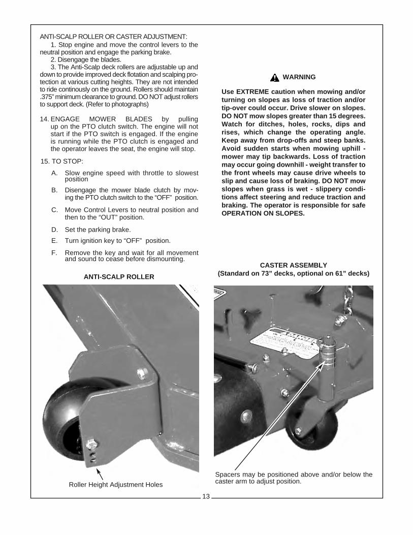
ANTI-SCALP ROLLER OR CASTER ADJUSTMENT:1. Stop engine and move the control levers to the
neutral position and engage the parking brake.2. Disengage the blades.3. The Anti-Scalp deck rollers are adjustable up and
down to provide improved deck flotation and scalping pro-tection at various cutting heights. They are not intendedto ride continously on the ground. Rollers should maintain.375” minimum clearance to ground. DO NOT adjust rollersto support deck. (Refer to photographs)
14. ENGAGE MOWER BLADES by pullingup on the PTO clutch switch. The engine will not start if the PTO switch is engaged. If the engineis running while the PTO clutch is engaged andthe operator leaves the seat, the engine will stop.
WARNING
Use EXTREME caution when mowing and/orturning on slopes as loss of traction and/ortip-over could occur. Drive slower on slopes.DO NOT mow slopes greater than 15 degrees.Watch for ditches, holes, rocks, dips andrises, which change the operating angle.Keep away from drop-offs and steep banks.Avoid sudden starts when mowing uphill -mower may tip backwards. Loss of tractionmay occur going downhill - weight transfer tothe front wheels may cause drive wheels toslip and cause loss of braking. DO NOT mowslopes when grass is wet - slippery condi-tions affect steering and reduce traction andbraking. The operator is responsible for safeOPERATION ON SLOPES.
15. TO STOP:
A. Slow engine speed with throttle to slowestposition
B. Disengage the mower blade clutch by mov-ing the PTO clutch switch to the “OFF” position.
C. Move Control Levers to neutral position and then to the “OUT” position.
D. Set the parking brake.
E. Turn ignition key to “OFF” position.
F. Remove the key and wait for all movementand sound to cease before dismounting.
ANTI-SCALP ROLLER
CASTER ASSEMBLY(Standard on 73” decks, optional on 61” decks)
Roller Height Adjustment HolesSpacers may be positioned above and/or below thecaster arm to adjust position.
13
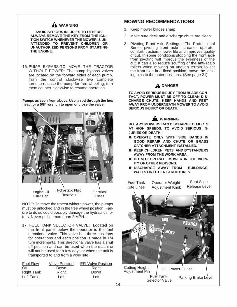
16. PUMP BYPASS-TO MOVE THE TRACTOR WITHOUT POWER: The pump bypass valves are located on the forward sides of each pump. Turn the control clockwise two complete turns to release the pump for free wheeling; turn them counter-clockwise to resume operation.
Pumps as seen from above. Use a rod through the hexhead, or a 5/8” wrench to open or close the valve.
WARNINGAVOID SERIOUS INJURIES TO OTHERS:
ALWAYS REMOVE THE KEY FROM THE IGNI-TION SWITCH WHENEVER THE MOWER IS UN-ATTENDED TO PREVENT CHILDREN ORUNAUTHORIZED PERSONS FROM STARTINGTHE ENGINE.
NOTE: To move the tractor without power, the pumpsmust be unlocked and in the free wheel position. Fail-ure to do so could possibly damage the hydraulic mo-tors. Never pull at more than 2 MPH.
17. FUEL TANK SELECTOR VALVE: Located onthe front panel below the operator is the fueldirectional valve. This valve has three positionsfor operations and each position is made in 1/4turn increments. This directional valve has a shutoff position and can be used when the machinewill not be used for a few days or when the unit istransported to and from a work site.
Fuel Flow Valve Position EFI Valve PositionOff Down RightRight Tank Right DownLeft Tank Left Left
MOWING RECOMMENDATIONS1. Keep mower blades sharp.
2. Make sure deck and discharge chute are clean.
3. Pivoting Front Axle Settings - The ProfessionalSeries pivoting front axle increases operator comfort, traction, mower life and improves qualityof cut. In some conditions stopping the front axlefrom pivoting will improve the evenness of thecut. It can also reduce scuffing of the anti-scalprollers when mowing on uneven terrain.To set the front axle in a fixed position, move the lock-ing pins to the outer positions. (See page 21)
ROTARY MOWERS CAN DISCHARGE OBJECTSAT HIGH SPEEDS. TO AVOID SERIOUS IN-JURIES OR DEATH:ll OPERATE ONLY WITH SIDE BANDS IN
GOOD REPAIR AND CHUTE OR GRASSCATCHER ATTACHMENT INSTALLED.
ll KEEP CHILDREN, PETS, AND BYSTANDERSAWAY FROM THE WORK AREA.
ll DO NOT OPERATE MOWER IN THE VICIN-ITY OF OTHER PERSONS.
ll DISCHARGE AWAY FROM BUILDINGS,WALLS OR OTHER STRUCTURES.
TO AVOID SERIOUS INJURY FROM BLADE CON-TACT, POWER MUST BE OFF TO CLEAN DIS-CHARGE CHUTE. KEEP HANDS AND FEETAWAY FROM UNDERNEATH MOWER TO AVOIDSERIOUS INJURY OR DEATH.
WARNING
Hydrostatic FluidReservoir
Cutting HeightAdjustment Pin
Fuel TankSelector Valve
14
Engine OilFiller Cap
ElectricalFuses
Operator WeightAdjustment Knob
DANGER
Fuel TankSite Lines
Seat SlideRelease Lever
DC Power Outlet
Parking Brake Lever

SECTION IIIMAINTENANCE
BEFORE PERFORMING ANY MAINTENANCE, TURN OFF ENGINE, REMOVE KEY AND DISCONNECT SPARKPLUGS. USE EXTREME CARE WHEN WORKING ON MACHINERY. DO NOT WEAR WATCH OR JEWELRY. DONOT WEAR LOOSE FITTING CLOTHES, AND OBSERVE ALL COMMON SAFETY PRACTICES WITH TOOLS.
CAUTION
MAINTENANCE SCHEDULESERVICE WHENCheck crankcase oil level before each useCheck air intake screen after each use
Clean grass from under deck after each use
Check tire pressure every 10 hours
Sharpen mower blades every 10 hours
Clean air filter element every 8 hours
Check 20W50 motor oil in hydrostatic system every 10 hours
Check drive belts every 50 hours(20 hr break-in)
Grease blade spindles every 50 hoursGrease front wheels every 50 hoursGrease caster wheel pivots every 50 hoursGrease pusher bar pivots every 50 hoursChange engine every 50 hourscrankcase oil and filter (5 hrs break-in)
Change hydrostatic oil and filter (See your Bush Hog Dealer)Important: Substitution of an improper filter will cause every 500 hourshydrostatic failure which will not be covered under warranty (50 hrs break-in)
Replace airfilter element annually or 500 hours
Check spark plugs annually or 100 hours
Service battery annually or 500 hours
Perform these maintenance procedures more frequently under extremely dusty, dirty conditions.Replace decals when illegible. Write parts dept. for free replacement.
WARNING: Make sure seat frame retention click-pins are in place after lifting seat pan for service.
15
IMPORTANT:BEFORE PERFORMING ANY SERVICE, MAINTENANCE OR REPAIR ON THE ENGINE, REFER TO THE RE-SPECTIVE ENGINE MANUFACTURERS’ MANUAL FOR SPECIFIC INFORMATION CONCERNING YOUR PAR-TICULAR BRAND OF ENGINE.
1. ENGINE:For complete maintenance and operating infor-mation for your engine, please refer to your engine operating and maintenance instructions furnished by the engine manufacturer andincluded in your Zero Turn mower information packet.
NOTEAir intake screen must be kept clean. Ifplugged, engine may be seriously dam-aged by over heating.
2. TACHOMETER / HOURMETERThe tachometer / hourmeter includes aFlashAlert feature to remind you to change engine oil and filter at recommended inter-vals. The tachometer displays engine rpm when the engine is running and elapsed time in hours when the engine is turned off.
Oil Change Flash Alert - Break-in interval at 5hours with 1 hour before and after flash. Normal interval at 50 hours with 2 hour before and after flash.
3. BATTERY:
When taking the battery out of the mower forservicing, make sure to reconnect the cables to the battery exactly as they were prior to removal.
Keep the battery clean. Remove the corrosionaround the battery terminals by applying a solu-tion of one part baking soda to four parts water.Coat all exposed terminal surfaces with a lightlayer of grease or petroleum jelly to prevent corrosion.
NOTEAt temperatures below 32 degrees F (0 deg C) the full charge state must be maintained to prevent cell electrolyte from freezing and causing permanent battery damage.
AVOID SERIOUS INJURY OR DEATH:ll THE BATTERY CONTAINS SULFURIC ACID.
AVOID CONTACT WITH SKIN, EYES OR CLOTHING.EYES - FLUSH WITH WATER AND GET PROMPT MED-ICAL ATTENTION.ANTIDOTE: INTERNAL - DRINK LARGE QUANTITIESOF WATER OR MILK. FOLLOW WITH MILK OF MAG-NESIA, BEATEN EGG OR VEGETABLE OIL. CALL APHYSICIAN IMMEDIATELY.
ll BATTERIES PRODUCE EXPLOSIVE GASES.KEEP SPARKS, FLAMES AND SMOKING MATERI-ALS AWAY. VENTILATE WHEN CHARGING IN AN ENCLOSED SPACE. WEAR EYE PROTECTION WHEN WORKING NEAR BATTERIES.
ll KEEP OUT OF REACH OF CHILDREN.
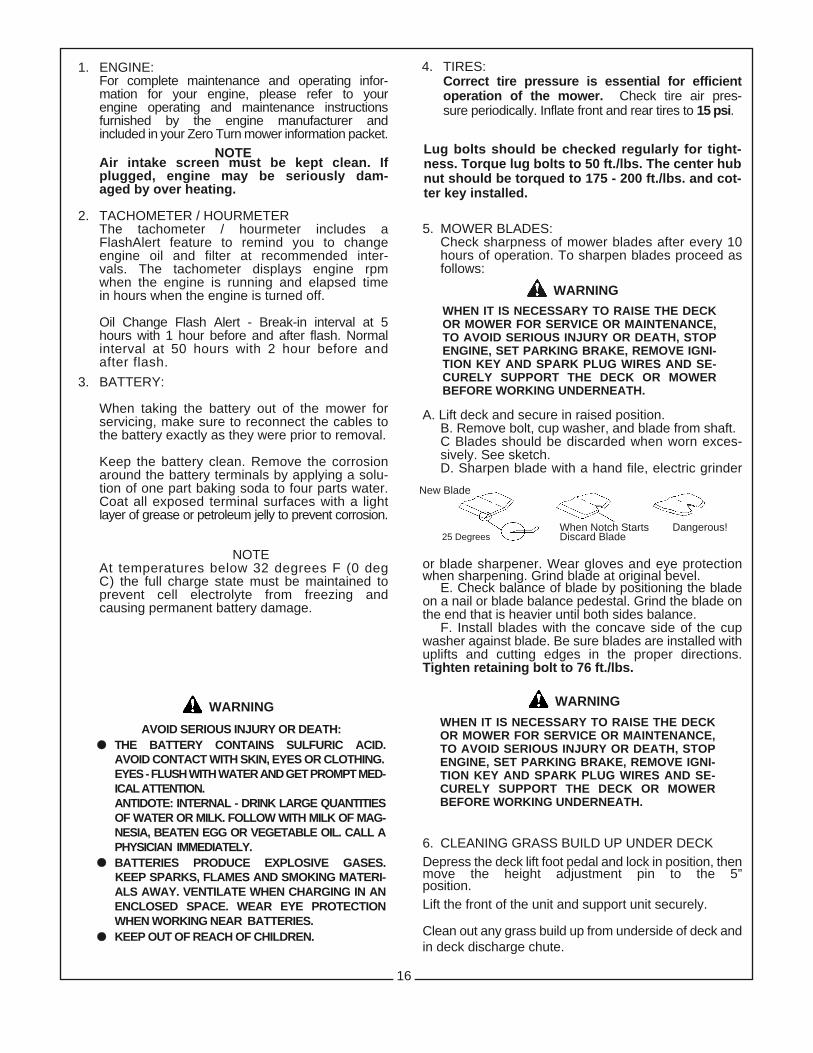
5. MOWER BLADES:Check sharpness of mower blades after every 10 hours of operation. To sharpen blades proceed asfollows:
A. Lift deck and secure in raised position. B. Remove bolt, cup washer, and blade from shaft.C Blades should be discarded when worn exces-sively. See sketch.D. Sharpen blade with a hand file, electric grinder
or blade sharpener. Wear gloves and eye protectionwhen sharpening. Grind blade at original bevel.
E. Check balance of blade by positioning the bladeon a nail or blade balance pedestal. Grind the blade onthe end that is heavier until both sides balance.
F. Install blades with the concave side of the cupwasher against blade. Be sure blades are installed withuplifts and cutting edges in the proper directions.Tighten retaining bolt to 76 ft./lbs.
6. CLEANING GRASS BUILD UP UNDER DECKDepress the deck lift foot pedal and lock in position, thenmove the height adjustment pin to the 5”position.Lift the front of the unit and support unit securely.
Clean out any grass build up from underside of deck andin deck discharge chute.
16
WHEN IT IS NECESSARY TO RAISE THE DECKOR MOWER FOR SERVICE OR MAINTENANCE,TO AVOID SERIOUS INJURY OR DEATH, STOPENGINE, SET PARKING BRAKE, REMOVE IGNI-TION KEY AND SPARK PLUG WIRES AND SE-CURELY SUPPORT THE DECK OR MOWERBEFORE WORKING UNDERNEATH.
New Blade
Dangerous!25 Degrees
When Notch StartsDiscard Blade
WARNING
Lug bolts should be checked regularly for tight-ness. Torque lug bolts to 50 ft./lbs. The center hubnut should be torqued to 175 - 200 ft./lbs. and cot-ter key installed.
WARNING
WHEN IT IS NECESSARY TO RAISE THE DECKOR MOWER FOR SERVICE OR MAINTENANCE,TO AVOID SERIOUS INJURY OR DEATH, STOPENGINE, SET PARKING BRAKE, REMOVE IGNI-TION KEY AND SPARK PLUG WIRES AND SE-CURELY SUPPORT THE DECK OR MOWERBEFORE WORKING UNDERNEATH.
WARNING
4. TIRES:Correct tire pressure is essential for efficientoperation of the mower. Check tire air pres-sure periodically. Inflate front and rear tires to 15 psi.
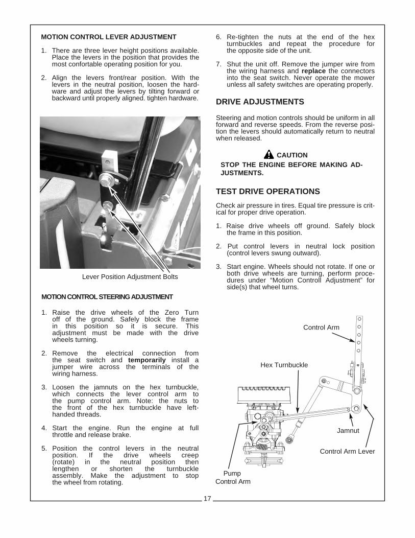
MOTION CONTROL STEERING ADJUSTMENT
1. Raise the drive wheels of the Zero Turnoff of the ground. Safely block the framein this position so it is secure. Thisadjustment must be made with the drivewheels turning.
2. Remove the electrical connection fromthe seat switch and temporarily install ajumper wire across the terminals of thewiring harness.
3. Loosen the jamnuts on the hex turnbuckle,which connects the lever control arm tothe pump control arm. Note: the nuts tothe front of the hex turnbuckle have left-handed threads.
4. Start the engine. Run the engine at fullthrottle and release brake.
5. Position the control levers in the neutralposition. If the drive wheels creep(rotate) in the neutral position thenlengthen or shorten the turnbuckleassembly. Make the adjustment to stopthe wheel from rotating.
6. Re-tighten the nuts at the end of the hexturnbuckles and repeat the procedure forthe opposite side of the unit.
7. Shut the unit off. Remove the jumper wire fromthe wiring harness and replace the connectorsinto the seat switch. Never operate the mowerunless all safety switches are operating properly.
DRIVE ADJUSTMENTS
Steering and motion controls should be uniform in allforward and reverse speeds. From the reverse posi-tion the levers should automatically return to neutralwhen released.
TEST DRIVE OPERATIONS
Check air pressure in tires. Equal tire pressure is crit-ical for proper drive operation.
1. Raise drive wheels off ground. Safely blockthe frame in this position.
2. Put control levers in neutral lock position(control levers swung outward).
3. Start engine. Wheels should not rotate. If one orboth drive wheels are turning, perform proce-dures under “Motion Controll Adjustment” forside(s) that wheel turns.
17
CAUTIONSTOP THE ENGINE BEFORE MAKING AD-JUSTMENTS.
MOTION CONTROL LEVER ADJUSTMENT
1. There are three lever height positions available.Place the levers in the position that provides themost confortable operating position for you.
2. Align the levers front/rear position. With thelevers in the neutral position, loosen the hard-ware and adjust the levers by tilting forward orbackward until properly aligned. tighten hardware.
Lever Position Adjustment Bolts
PumpControl Arm
Control Arm
Hex Turnbuckle
Jamnut
Control Arm Lever
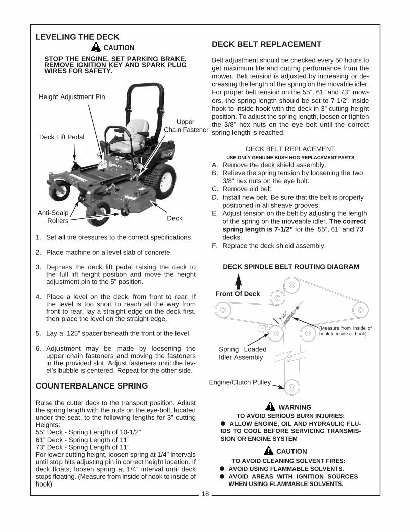
LEVELING THE DECK
1. Set all tire pressures to the correct specifications.
2. Place machine on a level slab of concrete.
3. Depress the deck lift pedal raising the deck tothe full lift height position and move the heightadjustment pin to the 5” position.
4. Place a level on the deck, from front to rear. If the level is too short to reach all the way from front to rear, lay a straight edge on the deck first,then place the level on the straight edge.
5. Lay a .125” spacer beneath the front of the level.
6. Adjustment may be made by loosening the upper chain fasteners and moving the fasteners in the provided slot. Adjust fasteners until the lev-el’s bubble is centered. Repeat for the other side.
COUNTERBALANCE SPRING
Raise the cutter deck to the transport position. Adjustthe spring length with the nuts on the eye-bolt, locatedunder the seat, to the following lengths for 3” cuttingHeights:55” Deck - Spring Length of 10-1/2”61” Deck - Spring Length of 11”73” Deck - Spring Length of 11”For lower cutting height, loosen spring at 1/4” intervalsuntil stop hits adjusting pin in correct height location. Ifdeck floats, loosen spring at 1/4” interval until deckstops floating. (Measure from inside of hook to inside ofhook)
STOP THE ENGINE, SET PARKING BRAKE,REMOVE IGNITION KEY AND SPARK PLUGWIRES FOR SAFETY.
CAUTION
DECK SPINDLE BELT ROUTING DIAGRAM
Spring LoadedIdler Assembly
Front Of Deck
WARNINGTO AVOID SERIOUS BURN INJURIES:
ll ALLOW ENGINE, OIL AND HYDRAULIC FLU-IDS TO COOL BEFORE SERVICING TRANSMIS-SION OR ENGINE SYSTEM
CAUTIONTO AVOID CLEANING SOLVENT FIRES:
ll AVOID USING FLAMMABLE SOLVENTS.ll AVOID AREAS WITH IGNITION SOURCES
WHEN USING FLAMMABLE SOLVENTS.
18
DECK BELT REPLACEMENT
Belt adjustment should be checked every 50 hours toget maximum life and cutting performance from themower. Belt tension is adjusted by increasing or de-creasing the length of the spring on the movable idler.For proper belt tension on the 55”, 61” and 73” mow-ers, the spring length should be set to 7-1/2” insidehook to inside hook with the deck in 3” cutting heightposition. To adjust the spring length, loosen or tightenthe 3/8” hex nuts on the eye bolt until the correctspring length is reached.
DECK BELT REPLACEMENTUSE ONLY GENUINE BUSH HOG REPLACEMENT PARTS
A. Remove the deck shield assembly.B. Relieve the spring tension by loosening the two
3/8” hex nuts on the eye bolt.C. Remove old belt.D. Install new belt. Be sure that the belt is properly
positioned in all sheave grooves.E. Adjust tension on the belt by adjusting the length
of the spring on the moveable idler. The correct spring length is 7-1/2” for the 55”, 61” and 73” decks.
F. Replace the deck shield assembly.
Engine/Clutch Pulley
Anti-ScalpRollers
Deck Lift Pedal
Height Adjustment Pin
Deck
UpperChain Fastener
(Measure from inside ofhook to inside of hook)
7-1/2”
WARNINGHIGH PRESSURE HYDRAULIC FLUID LEAKSCAN PENETRATE SKIN CAUSING SERIOUS IN-JURY AND GANGRENE.
INJECTED FLUID MUST BE SURGICALLY RE-MOVED WITHIN A FEW HOURS BY A DOCTORFAMILIAR WITH THIS TYPE OF INJURY.
TO AVOID SERIOUS INJURY FROMPRESSURE LEAKS:
ll USE CARDBOARD AND NOT HANDS TO SEARCH FOR LEAKS.
ll RELIEVE HYDRAULIC PRESSURE BEFOREWORKING ON SYSTEM.
ll CHECK HYDRAULIC HOSES, LINES, ANDCONNECTIONS FOR TIGHTNESS AND GOOD CONDITION BEFORE APPLYING SYSTEM PRESSURE.
START-UP MAINTENANCE
HYDROSTATIC FLUID
Bush Hog recommends the use of 20W50 motor oil inthe hydrostatic reservoir.
START-UP PROCEDURE
The following start-up procedure should always be fol-lowed when starting a new installation or when restart-ing and installation in which the pump or motor hasbeen removed from the system.
Prior to starting the pump, make certain all systemcomponents (reservoir, fittings, etc.) are clean prior tofilling with fluid.
Fill the reservoir with recommended fluid which shouldbe filtered prior to entering the reservoir.
Start the engine and idle at the lowest possible RPM.
With the bypass valve closed, slowly move the dis-placement control in both the forward and reverse di-rections. As air is purged from the unit, the oil level in
TO AVOID INJURY FROM EQUIPMENT GROUNDTRAVEL AND MOVEMENT DURING
START-UP PROCEDURE:DO NOT START OR JOG ENGINE UNTIL:ll PUMP IS IN NEUTRAL POSITIONll DRIVE WHEELS ARE RAISED OFF THE
GROUND.ll EQUIPMENT IS SECURELY BLOCKED-UP TO
KEEP WHEELS FROM GROUND CONTACT.ll PTO AND OTHER WORK FUNCTIONS ARE
DISCONNECTED.ll KEEP HANDS, HAIR AND CLOTHING AWAY
FROM ROTATING BLADES.
the reservoir will drop and bubbles may appear in thefluid. Refill the reservoir as necessary.
Place the steering levers in the neutral position andopen the bypass valve. Slowly move the steeringlevers in both the forward and reverse directions topurge the air from the closed circuit.
Close the bypass valve and run the unit in both direc-tions for several minutes until any remaining air ispurged from the unit. Refill the reservoir as necessary.
Stop the engine, check for and correct any fluid leaks,and check the reservoir level. Add fluid if necessary.The transmission is now ready for operation.
HYDROSTATIC MAINTENANCE
Check the reservoir daily for proper fluid level. Oil levelshould be to the bottom of the slot on the reservoir baf-fle.
The pump and motor units normally do not require reg-ular fluid changes. The system filter should be changedafter the first 50 hours of break-in, then every 500 hoursthereafter. The fluid and filter should be changed andthe system cleaned if the fluid becomes contaminatedwith foreign matter (water, dirt, etc.).
PARKING BRAKE ADJUSTMENT
Check to make sure brake is adjusted properly. Force on the brake handle to lock the brake in placeshould be 30 pounds. To adjust the brake tension,shorten or lengthen the horizontal brake linkage.
If further adjustment is needed at each individual wheelbrake:
1. Engage the brake lever (lever up).
2. Remove the wheel from the side needing adjusting.
3. With the brake engaged the spring length should be3-1/2” (measured to the inside of the spring loops).
4. If the spring length is different, shorten or lengthenthe vertical brake linkage.
5. Reinstall the wheel and torque the lug nuts.
Pump Drive Belt Tension Adjustment
1. Stop engine and remove key.
2. The pump drive belt tension is adjusted through aspring loaded idler pulley.
3. Adjust the eye bolt so the spring length is 6” (mea-sured to the inside of the spring loops).
19
WARNING

1. ENGINE IDLES POORLY:Carburetor maladjustment readjust carburetorImproper spark plug gap check and re-gap plug
2. ENGINE BACKFIRES:Carburetor maladjustment readjust carburetor
3. ENGINE RUNS BUT POWER UNIT WON’T MOVE FORWARDDrive belt loose or broken re-tension or replacePump shift arm disconnected reconnectHydrostatic reservoir oil low add oilPump bypass valve open put in closed positionHydrostatic oil filter plugged replace filterBad pump or motor consult dealer
4. POWER UNIT LOSES POWER OR HYDROSTAT SYSTEM OVERHEATSHydrostatic oil reservoir too low add oilPump or motor damaged consult dealerHydrostatic oil reservoir blowing oil out cap overfilled or water contaminated
5. ENGINE STALLS WHEN BLADES ARE ENGAGEDOperator not on seat sit on seatFaulty interlock system consult dealerBad blade spindle bearing consult dealerDeck drive belt not properly routed rerouteBlades blocked by foreign material clean under deck
•See engine manual for engine adjustments
ENGINE ELECTRICAL TROUBLE 1. ENGINE WILL NOT TURN OVER:
Dead batteryBad ground connectionBad terminal connection at batteryWiring harness plugs are not attached properlyat the key switch or the PTO switch
Bad parking brake switchBad PTO switch
TROUBLESHOOTING CHECK LIST
20
2. ENGINE WILL TURN OVER,BUT WILL NOT START:A. If there is spark at the plug:
No fuelBad fuel solenoid in engine
B. If there is no spark at the plug:Make sure safety interlock system is sequenced:
PTO switch is offControl levers in neutral positionParking brake is onOperator in seat
Check safety interlock switches:Seat switchNeutral switch
Bad ignition module on engine
POOR CUTTING PERFORMANCE
* ENGINE SPEED IS TOO SLOW:Always mow at full throttle.
* BELT SLIPPAGE:
Tighten deck adjusting spring to 7-1/2”.
* DECK IS PLUGGED WITH GRASS:
Clean underneath the mower.
* BLADES ARE NOT SHARP:
Sharpen the blades or replace.
* CUTTING HEIGHT:
Normal mowing - cut only 1/3 of the grass blade.
* FINISHED CUT IS UNEVEN:
Groundspeed is too fast.
* BLADES ARE WORN DOWN TOO FAR:
Replace your blades.
SECTION IVASSEMBLY
21
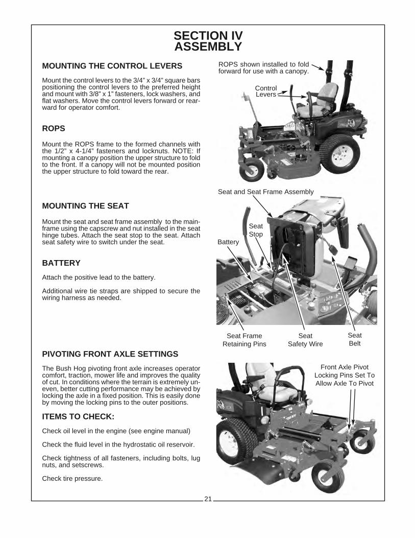
MOUNTING THE CONTROL LEVERS
Mount the control levers to the 3/4” x 3/4” square barspositioning the control levers to the preferred heightand mount with 3/8” x 1” fasteners, lock washers, andflat washers. Move the control levers forward or rear-ward for operator comfort.
ROPS
Mount the ROPS frame to the formed channels withthe 1/2” x 4-1/4” fasteners and locknuts. NOTE: Ifmounting a canopy position the upper structure to foldto the front. If a canopy will not be mounted positionthe upper structure to fold toward the rear.
MOUNTING THE SEAT
Mount the seat and seat frame assembly to the main-frame using the capscrew and nut installed in the seathinge tubes. Attach the seat stop to the seat. Attachseat safety wire to switch under the seat.
BATTERY
Attach the positive lead to the battery.
Additional wire tie straps are shipped to secure thewiring harness as needed.
PIVOTING FRONT AXLE SETTINGS
The Bush Hog pivoting front axle increases operatorcomfort, traction, mower life and improves the qualityof cut. In conditions where the terrain is extremely un-even, better cutting performance may be achieved bylocking the axle in a fixed position. This is easily doneby moving the locking pins to the outer positions.
ITEMS TO CHECK:
Check oil level in the engine (see engine manual)
Check the fluid level in the hydrostatic oil reservoir.
Check tightness of all fasteners, including bolts, lugnuts, and setscrews.
Check tire pressure.
ROPS shown installed to foldforward for use with a canopy.
Seat and Seat Frame Assembly
Seat Safety Wire
Front Axle PivotLocking Pins Set ToAllow Axle To Pivot
ControlLevers
SeatBelt
Seat FrameRetaining Pins
SeatStop
Battery

KAWASAKI ENGINE WIRING HARNESS
* NOTE: Use a 30 Amp fuse with linear actuator.
*
22

KOHLER ENGINE WIRING HARNESS
25 HP & 30HP MODELS
* NOTE: Use a 30 Amp fuse with linear actuator.
*
23

KOHLER ENGINE WIRING HARNESS
28 HP EFI ENGINE
* NOTE: Use a 30 Amp fuse with linear actuator.
*
24

SAFETY DECALSTo promote safe operation, Bush Hog supplies safety decals on all products manufactured. Because damage canoccur to safety decals either through shipment, use or reconditioning, Bush Hog will, upon request, provide safetydecals for any of our products in the field at no charge. Contact your authorized Bush Hog dealer for more infor-mation.
25
DANGER
KEEP AWAY!SHIELD MISSING FROM THIS AREA
TO AVOID SERIOUS INJURY OR DEATH, DONOT OPERATE WITHOUT THIS AND ALLOTHER SHIELDS IN PLACE AND IN GOODCONDITION. 823324WARNING
ROTATING DRIVE PARTS BENEATH• ENTANGLEMENT WITH ROTATING DRIVEPARTS CAN CAUSE INJURY OR DEATH.
• DO NOT OPERATE WITHOUT THIS ANDALL OTHER SHIELDS IN PLACE AND IN GOOD CONDITION. 50012615
SERIOUS INJURYOR DEATH MAYRESULT FROM
MACHINE ROLLOVER¥ Failure to follow these instructions could result in serious injury or death.
¥ Do not operate machine on st eep slopes or near drop offs.
¥ Avoid sharp and/or quick turns.
¥ Do not exceed the machine weight rating of the rops.
¥ Always use seat belt.
¥ Do not jump if machine tips.
¥ If ROPS is foldable ¡ Always keep the ROPS fully extended. ¡ WHEN ROPS MUST BE DOWN ¡ Do not use seat belt. ¡ Drive with extra care.
¥ If equipped with seat platform, Do not operate machine without seat platform pins in place.
50048632

26
TO AVOID SERIOUS INJURY OR DEATHDO NOT OPERATE MOWER WITHOUT DISCHARGE SHIELDOR DEFLECTOR IN PLACE AND GOOD REPAIR.
83056
WARNINGTO AVOID SERIOUS INJURY OR DEATH,
HREAD OPERATOR’S MANUAL BEFORE OPERATING & FOLLOW ALL PRECAUTIONS.(CONTACT DEALER FOR MANUALS)
HHLOWER IMPLEMENT, STOP ENGINE ANDREMOVE KEY BEFORE DISMOUNTING.
HHNO RIDERS. DO NOT OPERATE MOWER INVICINITY OF OTHER PERSONS.
HHALLOW NO CHILDREN OR UNQUALIFIEDPERSONS TO OPERATE EQUIPMENT.
HHCLEAR MOWING AREA OF DEBRIS.
HKEEP SHIELDS AND GUARDS IN PLACE.KEEP CLEAR OF DRIVES AND BELTS.
HHSECURELY SUPPORT MOWER &REMOVE KEY BEFORE WORKINGUNDERNEATH.
HHKNOW HOW TO STOP TRACTOR ANDEQUIPMENT QUICKLY IN ANEMERGENCY.
HHBE CAREFUL ON UNEVEN TERRAIN.DECREASE SPEED WHEN TURNING.
94134
WARNING

TORQUE SPECIFICATIONSProper toque for American fasteners used on Bush Hog equipment.
Recommended Torque in Foot Pounds (Newton Meters).*
Proper torque for metric fasteners used on Bush Hog equipment.Recommended torque in foot pounds (newton Meters).*
WRENCH BOLTSIZE DIA. ASTM ASTM ASTM ASTM
(mm) “A” (mm) “B” 4.6 8.8 9.8 10.98 5 1.8 (2.4) 5.1 (6.9) 6.5 (8.8)
10 6 3 (4) 8.7 (12) 11.1 (15)
13 8 7.3 (10) 21.1 (29) 27 (37)
16 10 14.5 (20) 42 (57) 53 (72)
18 12 25 (34) 74 (100) 73 (99) 93 (126)
21 14 40 (54) 118 (160) 116 (157) 148 (201)
24 16 62 (84) 167 (226) 181 (245) 230 (312)
30 20 122 (165) 325 (440) 449 (608)
33 22 443 (600) 611 (828)
36 24 211 (286) 563 (763) 778 (1054)
41 27 821 (1112) 1138 (1542)
46 30 418 (566) 1119 (1516) 1547 (2096)
*Use 75% of the specified torque value for plated fas-teners. Use 85% of the specified torque values for lu-bricated fasteners.
Numbers appearing on bolt headsindicate ASTM class.
METRIC
AMERICANBolt Head Markings
WrenchSize “A”
Bolt
Diameter “B”
SAE Grade 8(6 Dashes)
SAE Grade 2(No Dashes)
SAE Grade 5(3 Dashes)
WrenchSize “A” 8.8
Bolt
Diameter “B”
BOLT DIAMETERWRENCH (IN.) “B” AND SAE SAE SAE
SIZE (IN.) “A” THREAD SIZE GRADE 2 GRADE 5 GRADE 8
7/16 1/4 2O UNC 6 (7) 8 (11) 12 (16)
7/16 1/4 28 UNF 6 (8) 10 (13) 14 (18)
1/2 5/16 18 UNC 11 (15) 17 (23) 25 (33)
1/2 5/16 24 UNF 13 (17) 19 (26) 27 (37)
9/16 3/8 16 UNC 20 (27) 31 (42) 44 (60)
9/16 3/8 24 UNF 23 (31) 35 (47) 49 (66)
5/8 7/16 14 UNC 32 (43) 49 (66) 70 (95)
5/8 7/16 20 UNF 36 (49) 55 (75) 78 (106)
3/4 1/2 13 UNC 49 (66) 76 (103) 106 (144)
3/4 1/2 20 UNF 55 (75) 85 (115) 120 (163)
7/8 9/16 12 UNC 70 (95) 109 (148) 153 (207)
7/8 9/16 18 UNF 79 (107) 122 (165) 172 (233)
15/16 5/8 11 UNC 97 (131) 150 (203) 212 (287)
15/16 5/8 18 UNF 110 (149) 170 (230) 240 (325)
1 1/8 3/4 10 UNC 144 (195) 266 (360) 376 (509)
1 1/8 3/4 16 UNF 192 (260) 297 (402) 420 (569)
1 5/16 7/8 9 UNC 166 (225) 430 (583) 606 (821)
1 5/16 7/8 14 UNF 184 (249) 474 (642) 668 (905)
1 1/2 1 8 UNC 250 (339) 644 (873) 909 (1232)
1 1/2 1 12 UNF 274 (371) 705 (955) 995 (1348)
1 1/2 1 14 UNF 280 (379) 721 (977) 1019 (1381)
1 11/16 1 1/8 7 UNC 354 (480) 795 (1077) 1288(1745)
1 11/16 1 1/8 12 UNF 397 (538) 890 (1206) 1444 (1957)
1 7/8 1 1/4 7 UNC 500 (678) 1120 (1518) 1817 (2462)
1 7/8 1 1/4 12 UNF 553 (749) 1241 (1682) 2013 (2728)
2 1/16 1 3/8 6 UNC 655 (887) 1470 (1992) 2382 (3228)
2 1/16 1 3/8 12 UNF 746 (1011) 1672 (2266) 2712 (3675)
2 1/4 1 1/2 6 UNC 870 (1179) 1950 (2642) 3161 (4283)
2 1/4 1 1/2 12 UNF 979 (1327) 2194 (2973) 3557 (4820)
27

PROFESSIONAL SERIESZERO TURN RIDING MOWERS
Optional Equipment:
Caster Bundle (Available for 61” deck only)
Canopy Kit
Light Kit
Electric Actuator Bundle
Rear Hitch Kit
Mulching Kit 61”
Mulching Kit 55”
Striping Kit
Grass Catcher 55” & 61”
28
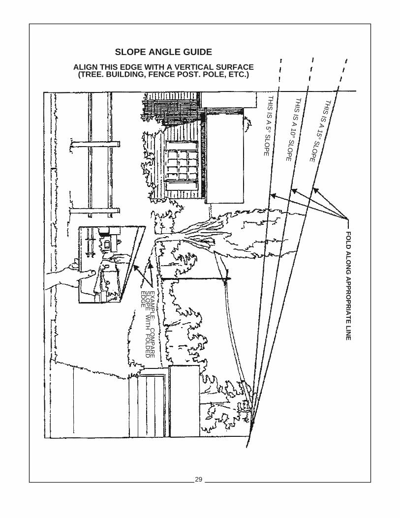
SLOPE ANGLE GUIDEALIGN THIS EDGE WITH A VERTICAL SURFACE(TREE. BUILDING, FENCE POST. POLE, ETC.)
FOLD ALONG APPROPRIATE LIN
E
EX
AM
PLE
: C
OM
PA
RE
SLO
PE
W
ITH
F
OLD
ED
ED
GE
THIS
IS A
15° SLO
PE
THIS
IS A
10° SLO
PE
THIS
IS A
5° SLO
PE
29

TO THE OWNER/OPERATOR/DEALER
To keep your implement running efficiently and safely, read your manual thoroughly and follow these directionsand the Safety Messages in this Manual. The Table of Contents clearly identifies each section where you caneasily find the information you need.The OCCUPATIONAL SAFETY AND HEALTH ACT (1928.51 Subpart C) makes these minimum safetyrequirements of tractor operators:
REQUIRED OF THE OWNER:1. Provide a Roll-Over-Protective Structure that meets the requirements of this Standard; and2. Provide Seat belts that meet the requirements of this paragraph of this Standard and SAE J4C; and3. Ensure that each employee uses such Seat belt while the tractor is moving; and4. Ensure that each employee tightens the Seat belt sufficiently to confine the employee to the protected area provided by the ROPS
REQUIRED OF THE OPERATOR:1. Securely fasten seat belt if the tractor has a ROPS.2. Where possible, avoid operating the tractor near ditches, embankments, and holes.3. Reduce speed when turning, crossing slopes, and on rough, slick, or muddy surfaces.4. Stay off slopes too steep for safe operation.5. Watch where you are going - especially at row ends, on roads, and around trees.6. Do not permit others to ride.7. Operate the tractor smoothly - no jerky turns, starts, or stops.8. Hitch only to the drawbar and hitch points recommended by the tractor manufacturer.9. When the tractor is stopped, set brakes securely and use park lock, if available.
x Keep children away from danger all day, every day...
x Equip tractors with rollover protection (ROPS) and keep all machinery guards in place...
x Please work, drive, play and live each day with care and concern for your safety and that of your family and fellow citizens.

PZ -SOM - 04/11 P/N 50045565 Printed U.S.A.
PROFESSIONAL SERIESZEROTURN RIDING MOWER