Series 90 Micro Programmable Logic Controller Self-Teach ...ucc.colorado.edu/fanuc/gfk1104a.pdf ·...
77
GE Fanuc Automation Programmable Control Products Series 90 Micro Programmable Logic Controller Self-Teach Manual GFK-1104A May 1996 GE FANUC
Transcript of Series 90 Micro Programmable Logic Controller Self-Teach ...ucc.colorado.edu/fanuc/gfk1104a.pdf ·...
ÎÎ
GE Fanuc Automation
Programmable Control Products
Series 90� Micro
Programmable Logic Controller
Self-Teach Manual
GFK-1104A May 1996
GE FANUC
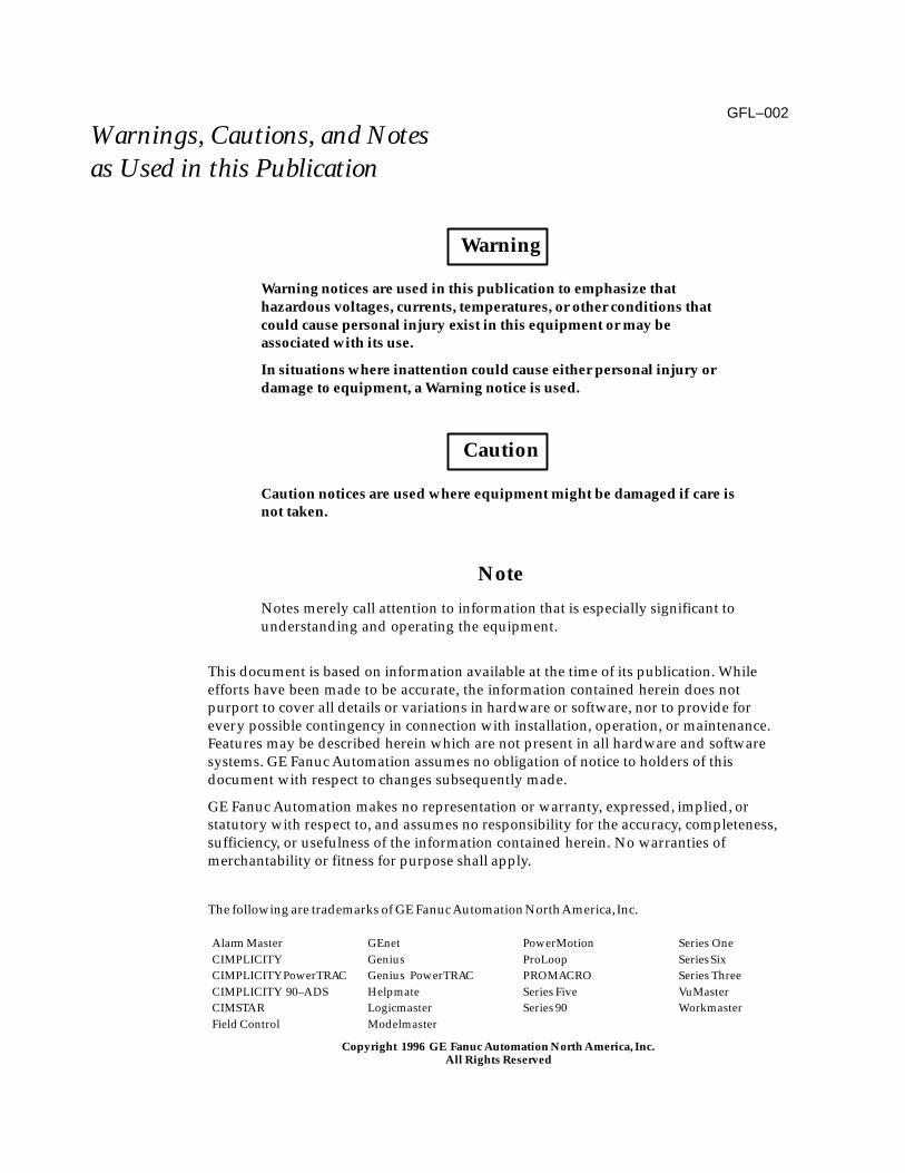
GFL–002
Warnings, Cautions, and Notesas Used in this Publication
Warning
Warning notices are used in this publication to emphasize thathazardous voltages, currents, temperatures, or other conditions thatcould cause personal injury exist in this equipment or may beassociated with its use.
In situations where inattention could cause either personal injury ordamage to equipment, a Warning notice is used.
Caution
Caution notices are used where equipment might be damaged if care isnot taken.
Note
Notes merely call attention to information that is especially significant tounderstanding and operating the equipment.
This document is based on information available at the time of its publication. Whileefforts have been made to be accurate, the information contained herein does notpurport to cover all details or variations in hardware or software, nor to provide forevery possible contingency in connection with installation, operation, or maintenance.Features may be described herein which are not present in all hardware and softwaresystems. GE Fanuc Automation assumes no obligation of notice to holders of thisdocument with respect to changes subsequently made.
GE Fanuc Automation makes no representation or warranty, expressed, implied, orstatutory with respect to, and assumes no responsibility for the accuracy, completeness,sufficiency, or usefulness of the information contained herein. No warranties ofmerchantability or fitness for purpose shall apply.
The following are trademarks of GE Fanuc Automation North America, Inc.
Alarm MasterCIMPLICITYCIMPLICITY PowerTRACCIMPLICITY 90–ADSCIMSTARField Control
GEnetGeniusGenius PowerTRACHelpmateLogicmasterModelmaster
PowerMotionProLoopPROMACROSeries FiveSeries 90
Series OneSeries SixSeries ThreeVuMasterWorkmaster
Copyright 1996 GE Fanuc Automation North America, Inc.All Rights Reserved
Series 90� Micro Programmable Logic Controller Self-Teach Manual – May 1996 iiiGFK-1104A
Preface
The purpose of this manual is to help you become familiar with the use of the Series 90Micro Programmable Logic Controller (PLC).
Refer to “Getting Started” on page 3-1 for a list of items you will need.
Revisions to This Manual
The following list describes the revisions made to this manual as compared to theprevious version (GFK-1104).
� Product listing on page 3-1 updated to include 28-point Micro PLCs. Wiringdiagrams for 28-point PLCs provided on pages 3-5 and 3-6.
� Description of input switches on page 3-2 revised to include input devices other thanthe Simulator Box (44A76988-001).
� Wiring diagram for AC In/AC Out modules (page 3-4) revised. (Previous versioncontained a note concerning high speed counter inputs that does not apply to ACIn/AC Out models.)
� Other corrections and clarifications, including additional index entries.
Related Publications
This manual should be used with the Series 90 Micro Programmable Logic ControllerUser’s Manual (GFK-1065), which contains detailed information about the installationand operation of the Series 90 Micro PLC.
You will find several programming examples in this manual. If you are not familiar withthe functions used in ladder logic, refer to the following documents.
Logicmaster 90�-30/20/Micro Programming Software User’s Manual (GFK-0466)
Series 90�-30/20/Micro Programmable Controllers Reference Manual (GFK-0467)
Series 90�-30 and 90-20 Hand-held Programmer User’s Manual (GFK-0402).
Workmaster� II PLC Programming Unit Guide to Operation (GFK-0401)
GE FANUC
Preface
Series 90� Micro Programmable Logic Controller Self-Teach Manual – May 1996 iv GFK-1104A
Content of This Manual
The material in this manual is presented in two sections:
Section 1
Lessons 1 and 2 briefly explain the basics of programmable controllers.
Lesson 1. PLC Basics. Describes the general principles of PLC operation.
Lesson 2. PLC Application. Describes a simple PLC application that will be used as anexample later in this manual.
Section 2
Lessons 3 through 8 focus on the use of Logicmaster 90 Micro configuration andprogramming software with the Series 90 Micro PLC.
Lesson 3. Setup. Describes how to setup the hardware for the exercises in this manual.
Lesson 4. Basic Configuration. Describes software configuration of the Series 90 MicroPLC.
Lesson 5. Beginning Programming. Walks you through the process of creating andtesting a simple one-line ladder logic program.
Lesson 6. More Programming. Provides instructions for creating a ladder-logic programfor the application described in lesson 2.
Lesson 7. Ladder and Data Monitoring. Describes the use of various data table functionsprovided by the Logicmaster 90 software
Lesson 8. Printing. Describes how to use Logicmaster 90 software print functions to printladder logic and configuration data.
GE Fanuc Bulletin Board SystemIf you have a modem, you might wish to register on the GE Fanuc PLC BulletinBoard System (BBS). Updates of programs will be provided in the PLC filessection as they become available. Eight rolling nodes available.
804-978-5458 (14400 to 2400 autobaud, no parity, 8 data bits, 1 stop bit).
We Welcome Your Comments and Suggestions
At GE Fanuc automation, we strive to produce quality technical documentation. Afteryou have used this manual, please take a few moments to complete and return theReader ’s Comment Card located on the next page.
Libby AllenSenior Technical Writer

Contents
vGFK-1104A Series 90�-30 Micro Programmable Logic Controller Self-Teach Manual – May 1996
Lesson 1 PLC Basics 1-1. . . . . . . . . . . . . . . . . . . . . . . . . . . . . . . . . . . . . . . . . . . . . . . . .
Definition 1-1. . . . . . . . . . . . . . . . . . . . . . . . . . . . . . . . . . . . . . . . . . . . . . . . . . . . . . .
I/O Interface 1-3. . . . . . . . . . . . . . . . . . . . . . . . . . . . . . . . . . . . . . . . . . . . . . . . . . . . .
General 1-3. . . . . . . . . . . . . . . . . . . . . . . . . . . . . . . . . . . . . . . . . . . . . . . . . . . . . .
Series 90 Micro PLC I/O Circuits 1-4. . . . . . . . . . . . . . . . . . . . . . . . . . . . . . . . .
Central Processor Unit 1-5. . . . . . . . . . . . . . . . . . . . . . . . . . . . . . . . . . . . . . . . . . . . .
Ladder Diagrams 1-5. . . . . . . . . . . . . . . . . . . . . . . . . . . . . . . . . . . . . . . . . . . . . . . . .
Lesson 2 Basic PLC Application 2-1. . . . . . . . . . . . . . . . . . . . . . . . . . . . . . . . . . . . . . .
PLC Application 2-1. . . . . . . . . . . . . . . . . . . . . . . . . . . . . . . . . . . . . . . . . . . . . . . . . .
Ladder Diagram 2-2. . . . . . . . . . . . . . . . . . . . . . . . . . . . . . . . . . . . . . . . . . . . . . . . . .
Lesson 3Setup 3-1. . . . . . . . . . . . . . . . . . . . . . . . . . . . . . . . . . . . . . . . . . . . . . . . . . . . . . . . .
Getting Started 3-1. . . . . . . . . . . . . . . . . . . . . . . . . . . . . . . . . . . . . . . . . . . . . . . . . . .
Input Switches 3-3. . . . . . . . . . . . . . . . . . . . . . . . . . . . . . . . . . . . . . . . . . . . . . . . . . .
Wire Connection Information 3-4. . . . . . . . . . . . . . . . . . . . . . . . . . . . . . . . . . . . . .
Power Supply and I/O Connections 3-4. . . . . . . . . . . . . . . . . . . . . . . . . . . . . .
General Wiring Practices 3-4. . . . . . . . . . . . . . . . . . . . . . . . . . . . . . . . . . . . . . . .
Procedure for Power Connections 3-4. . . . . . . . . . . . . . . . . . . . . . . . . . . . . . . .
Power-up Sequence 3-8. . . . . . . . . . . . . . . . . . . . . . . . . . . . . . . . . . . . . . . . . . . . . . .
Connecting a Programming Device 3-8. . . . . . . . . . . . . . . . . . . . . . . . . . . . . . . . .
Installing the Programming Software 3-9. . . . . . . . . . . . . . . . . . . . . . . . . . . . . . . .
Lesson 4 Basic Configuration 4-1. . . . . . . . . . . . . . . . . . . . . . . . . . . . . . . . . . . . . . . . .
Getting Started 4-1. . . . . . . . . . . . . . . . . . . . . . . . . . . . . . . . . . . . . . . . . . . . . . . . . . .
Screen Elements 4-4. . . . . . . . . . . . . . . . . . . . . . . . . . . . . . . . . . . . . . . . . . . . . . . . . .
Running and Stopping the Series 90 Micro PLC 4-5. . . . . . . . . . . . . . . . . . . . . . .
Configuring the Series 90 Micro PLC 4-8. . . . . . . . . . . . . . . . . . . . . . . . . . . . . . . .
Lesson 5 Beginning Programming 5-1. . . . . . . . . . . . . . . . . . . . . . . . . . . . . . . . . . . . .
Getting Started 5-1. . . . . . . . . . . . . . . . . . . . . . . . . . . . . . . . . . . . . . . . . . . . . . . . . . .
Creating a Program 5-3. . . . . . . . . . . . . . . . . . . . . . . . . . . . . . . . . . . . . . . . . . . . . . .
Transferring Your Program to the PLC 5-5. . . . . . . . . . . . . . . . . . . . . . . . . . . . . . .
Running Your Program 5-6. . . . . . . . . . . . . . . . . . . . . . . . . . . . . . . . . . . . . . . . . . . .
Copying Your Program to a Diskette 5-7. . . . . . . . . . . . . . . . . . . . . . . . . . . . . . . . .
Loading a File 5-9. . . . . . . . . . . . . . . . . . . . . . . . . . . . . . . . . . . . . . . . . . . . . . . . . . . .
GE FANUC

Contents
vi Series 90�-30 Micro Programmable Logic Controller Self-Teach Manual – May 1996 GFK-1104A
Lesson 6 More Programming 6-1. . . . . . . . . . . . . . . . . . . . . . . . . . . . . . . . . . . . . . . . .
Getting Started 6-1. . . . . . . . . . . . . . . . . . . . . . . . . . . . . . . . . . . . . . . . . . . . . . . . . . .
Clearing Memory 6-2. . . . . . . . . . . . . . . . . . . . . . . . . . . . . . . . . . . . . . . . . . . . . . . . .
Creating a New Folder 6-3. . . . . . . . . . . . . . . . . . . . . . . . . . . . . . . . . . . . . . . . . . . .
Variable Declarations 6-5. . . . . . . . . . . . . . . . . . . . . . . . . . . . . . . . . . . . . . . . . . . . . .
Entering the Ladder Logic Into the Programmer 6-7. . . . . . . . . . . . . . . . . . . . . .
Editing Tips 6-7. . . . . . . . . . . . . . . . . . . . . . . . . . . . . . . . . . . . . . . . . . . . . . . . . . .
Drawing the Rest Of The Logic 6-8. . . . . . . . . . . . . . . . . . . . . . . . . . . . . . . . . .
Searching 6-9. . . . . . . . . . . . . . . . . . . . . . . . . . . . . . . . . . . . . . . . . . . . . . . . . . . . .
Viewing the Variable Declarations Table 6-10. . . . . . . . . . . . . . . . . . . . . . . . . . .
Editing the Variable Declarations Table 6-10. . . . . . . . . . . . . . . . . . . . . . . . . . . .
Testing Your Program 6-11. . . . . . . . . . . . . . . . . . . . . . . . . . . . . . . . . . . . . . . . . . . . .
Lesson 7 Data Monitoring 7-1. . . . . . . . . . . . . . . . . . . . . . . . . . . . . . . . . . . . . . . . . . . .
Getting Started 7-1. . . . . . . . . . . . . . . . . . . . . . . . . . . . . . . . . . . . . . . . . . . . . . . . . . .
Viewing Data Tables 7-2. . . . . . . . . . . . . . . . . . . . . . . . . . . . . . . . . . . . . . . . . . . . . .
Creating a Mixed Table 7-4. . . . . . . . . . . . . . . . . . . . . . . . . . . . . . . . . . . . . . . . . . . .
Viewing %AI References 7-5. . . . . . . . . . . . . . . . . . . . . . . . . . . . . . . . . . . . . . . . . . .
Writing in the Tables 7-6. . . . . . . . . . . . . . . . . . . . . . . . . . . . . . . . . . . . . . . . . . . . . .
Lesson 8 Printing 8-1. . . . . . . . . . . . . . . . . . . . . . . . . . . . . . . . . . . . . . . . . . . . . . . . . . . .
Getting Started 8-1. . . . . . . . . . . . . . . . . . . . . . . . . . . . . . . . . . . . . . . . . . . . . . . . . . .
Sending a Ladder Diagram to the Printer 8-2. . . . . . . . . . . . . . . . . . . . . . . . . . . . .
Sending the Document to a File 8-5. . . . . . . . . . . . . . . . . . . . . . . . . . . . . . . . . . . . .
Printing the Hardware Configuration 8-6. . . . . . . . . . . . . . . . . . . . . . . . . . . . . . .
Screen Print 8-8. . . . . . . . . . . . . . . . . . . . . . . . . . . . . . . . . . . . . . . . . . . . . . . . . . . . . .
Appendix A High Speed Counter Applications A-1. . . . . . . . . . . . . . . . . . . . . . . . . . . .
Counter Cascading A-2. . . . . . . . . . . . . . . . . . . . . . . . . . . . . . . . . . . . . . . . . . . . . . .
RPM Indicator A-3. . . . . . . . . . . . . . . . . . . . . . . . . . . . . . . . . . . . . . . . . . . . . . . . . . .
Tolerance Checking A-4. . . . . . . . . . . . . . . . . . . . . . . . . . . . . . . . . . . . . . . . . . . . . . .
Measuring Pulse Time A-5. . . . . . . . . . . . . . . . . . . . . . . . . . . . . . . . . . . . . . . . . . . .
Measuring Total Material Length A-6. . . . . . . . . . . . . . . . . . . . . . . . . . . . . . . . . . .
Material Handling Conveyor Control A-7. . . . . . . . . . . . . . . . . . . . . . . . . . . . . . .
Timing Pulse Generation A-8. . . . . . . . . . . . . . . . . . . . . . . . . . . . . . . . . . . . . . . . . .
Contents
viiGFK-1104A Series 90�-30 Micro Programmable Logic Controller Self-Teach Manual – May 1996
Figure 1-1. PLC Block Diagram 1-1. . . . . . . . . . . . . . . . . . . . . . . . . . . . . . . . . . . . . . . . . . . . . . . . . . . . . . . . . . .
Figure 1-2. PLC Sweep Sequence 1-2. . . . . . . . . . . . . . . . . . . . . . . . . . . . . . . . . . . . . . . . . . . . . . . . . . . . . . . . .
Figure 1-3. Typical Input/Output Circuitry 1-3. . . . . . . . . . . . . . . . . . . . . . . . . . . . . . . . . . . . . . . . . . . . . . . . .
Figure 1-4. Ladder Diagram Example 1-5. . . . . . . . . . . . . . . . . . . . . . . . . . . . . . . . . . . . . . . . . . . . . . . . . . . . .
Figure 2-1. Feed Pump Example 2-1. . . . . . . . . . . . . . . . . . . . . . . . . . . . . . . . . . . . . . . . . . . . . . . . . . . . . . . . . .
Figure 2-2. Ladder Logic for Feed Pump Example 2-2. . . . . . . . . . . . . . . . . . . . . . . . . . . . . . . . . . . . . . . . . . .
Figure 3-1. Field Wiring Diagrams 3-5. . . . . . . . . . . . . . . . . . . . . . . . . . . . . . . . . . . . . . . . . . . . . . . . . . . . . . . .
Figure 4-1. Common Screen Elements 4-4. . . . . . . . . . . . . . . . . . . . . . . . . . . . . . . . . . . . . . . . . . . . . . . . . . . . .
GE FANUC
1section level 1 figure bi level 1 table_big level 1
Restarts for autonumbers that do not restart in eachchapter.figure bi level 1, reset table_big level 1, reset chap_big level 1, reset1app_big level 1, resetAfigure_ap level 1, resettable_ap level 1, resetfigure level 1, reset table level 1, reset Table 1.
these restarts must be in the header frame of chapter 1.a:ebx, l 1 resetAa:obx:l 1, resetAa:bigbx level 1 resetAa:ftr level 1 resetAc:ebx, l 1 reset1c:obx:l 1, reset1c:bigbx level 1 reset1c:ftr level 1 reset1
Reminders for autonumbers that need to be restartedmanually (first instance will always be 4) let_in level 1: A. B. C. letter level 1:A.B.C.num level 1: 1. 2. 3.num_in level 1: 1. 2. 3.rom_in level 1: I. II. III.roman level 1: I. II. III. steps level 1: 1. 2. 3.
1-1GFK-1104A
Chapter 1 PLC Basics
When you complete this lesson, you will have learned:
� How I/O functions in a PLC system
� How the CPU executes a program
� About memory in the PLC
� About the CPU scan
� The fundamentals of ladder diagrams
Definition
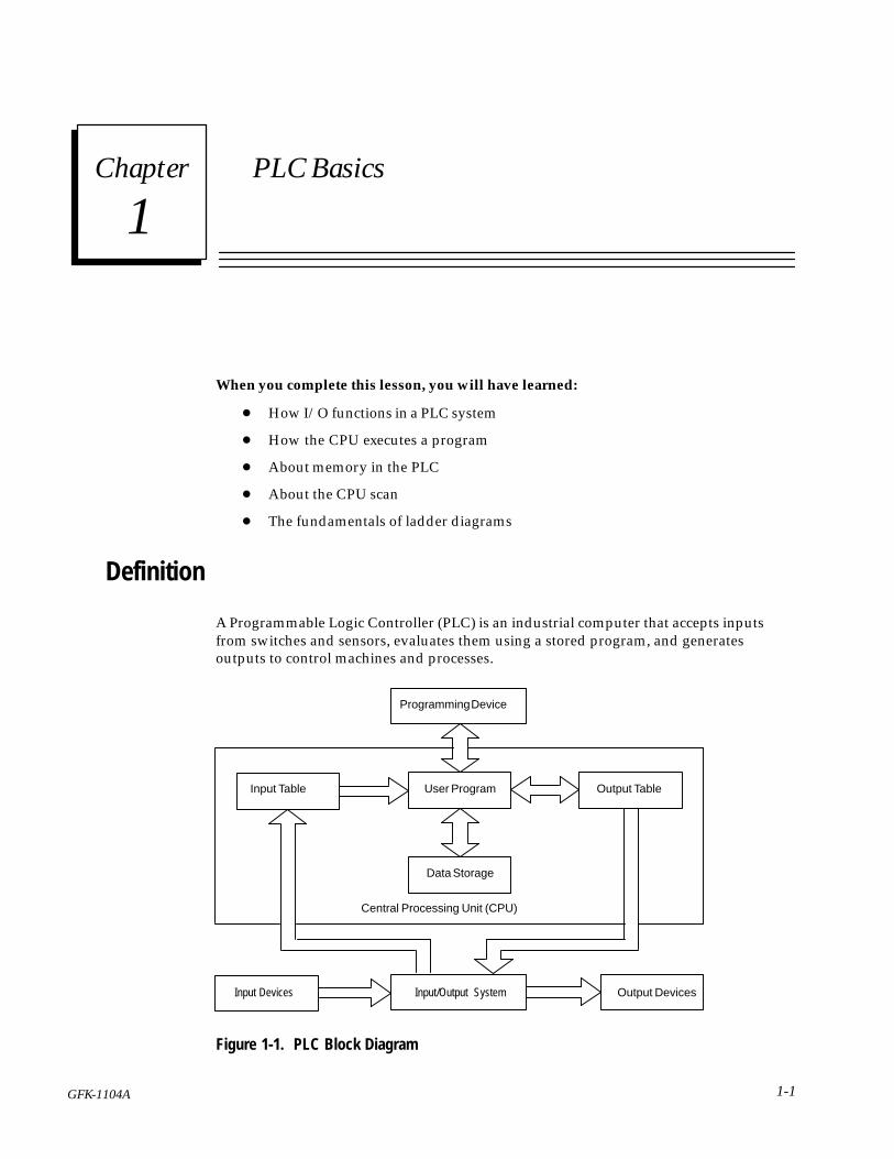
A Programmable Logic Controller (PLC) is an industrial computer that accepts inputsfrom switches and sensors, evaluates them using a stored program, and generatesoutputs to control machines and processes.
Programming Device
Input Table User Program Output Table
Data Storage
Central Processing Unit (CPU)
Input/Output SystemInput Devices Output Devices
Figure 1-1. PLC Block Diagram
1
1-2 Series 90� Micro Programmable Logic Controller Self-Teach Manual – May 1996 GFK-1104A
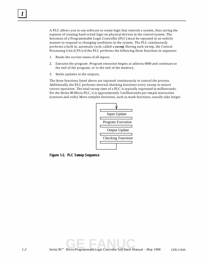
A PLC allows you to use software to create logic that controls a system, thus saving theexpense of creating hard-wired logic on physical devices in the control system. Thefunctions of a Programmable Logic Controller (PLC) must be repeated in an orderlymanner to respond to changing conditions in the system. The PLC continuouslyperforms a built in, automatic cycle, called a sweep. During each sweep, the CentralProcessing Unit (CPU) of the PLC performs the following three functions in sequence:
1. Reads the current states of all inputs.
2. Executes the program. Program execution begins at address 0000 and continues tothe end of the program, or to the end of the memory.
3. Sends updates to the outputs.
The three functions listed above are repeated continuously to control the process.Additionally, the PLC performs internal checking functions every sweep to ensurecorrect operation. The total sweep time of a PLC is typically expressed in milliseconds.For the Series 90 Micro PLC, it is approximately 5 milliseconds per simple instruction(contacts and coils). More complex functions, such as math functions, usually take longer.
Input Update
Program Execution
Output Update
Checking Functions
Figure 1-2. PLC Sweep Sequence
GE FANUC
1
1-3GFK-1104A Chapter 1 PLC Basics
I/O Interface
General
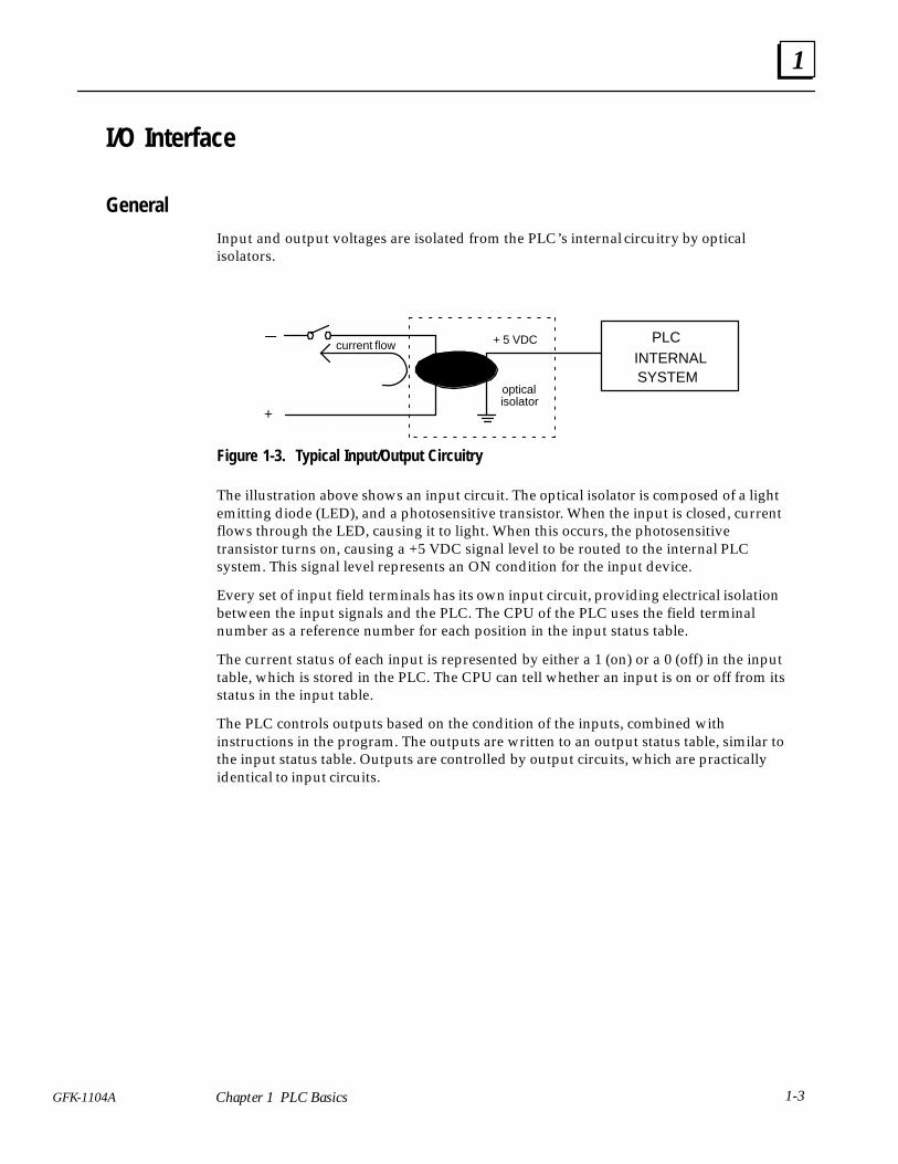
Input and output voltages are isolated from the PLC’s internal circuitry by opticalisolators.
PLCINTERNALSYSTEM
+ 5 VDC
isolator+
_current flow
optical
Figure 1-3. Typical Input/Output Circuitry
The illustration above shows an input circuit. The optical isolator is composed of a lightemitting diode (LED), and a photosensitive transistor. When the input is closed, currentflows through the LED, causing it to light. When this occurs, the photosensitivetransistor turns on, causing a +5 VDC signal level to be routed to the internal PLCsystem. This signal level represents an ON condition for the input device.
Every set of input field terminals has its own input circuit, providing electrical isolationbetween the input signals and the PLC. The CPU of the PLC uses the field terminalnumber as a reference number for each position in the input status table.
The current status of each input is represented by either a 1 (on) or a 0 (off) in the inputtable, which is stored in the PLC. The CPU can tell whether an input is on or off from itsstatus in the input table.
The PLC controls outputs based on the condition of the inputs, combined withinstructions in the program. The outputs are written to an output status table, similar tothe input status table. Outputs are controlled by output circuits, which are practicallyidentical to input circuits.

1
1-4 Series 90� Micro Programmable Logic Controller Self-Teach Manual – May 1996 GFK-1104A
Series 90 Micro PLC I/O Circuits
DC Input/Relay Output Models (IC693UDR001/002/005)7
Refer to Chapter 3 in the Series 90 Micro PLC User’s Manual – GFK-1065 for detaileddescriptions of the I/O circuitry.
DC Input Circuits
The DC input circuits condition and filter 24 VDC input voltages so that they can beproperly detected by the CPU module.
The DC inputs can be used as a regular inputs, or to supply count and preload/strobeinputs for the high speed counters (HSCs). For details on the operation of HSCs, seeChapter 6 in GFK-1065. Also, Appendix A in this manual provides some generalexamples of applications for HSCs.
Relay Output Circuits The six 2A, isolated, normally open output circuits allow the low level signals from theCPU module to control relay devices. The outputs can be configured as regular outputsor as outputs controlled by the HSCs.
AC Input/AC Output Models (IC693UAA003/007)
AC Input Circuits
Eight 120 VAC, 50/60 Hz input points are provided in two groups, with four inputs ineach group.
Input characteristics are compatible with a wide range of user-supplied input devices,such as pushbuttons, limit switches, and electronic proximity switches.
AC Output Circuits
Six AC 120 VAC, 50/60 Hz, 0.5 A output points are provided in two groups. The firstgroup has four points/common, and the second group has two points/common.
Potentiometer Inputs (IC693UDR001/002, IC693UAA003) Two potentiometers are provided to allow adjustment of the values in analog registers%AI16 and %AI17. The potentiometers can be turned by inserting a small screwdriverthrough an access hole in the Micro PLC front panel.
This feature could be used to set threshold values that are used in logic relationshipswith other inputs/outputs.
GE FANUC
1
1-5GFK-1104A Chapter 1 PLC Basics
Central Processor UnitThe CPU is the section of the PLC that coordinates, sequences, utilizes, and controls allother parts of the system. The CPU executes the program, performing each instructionin the order that it appears in the program. The main components of the CPU includethe microprocessor, the internal operating system software, and memory.
There are several types of memories used in computer systems. The predominant type iscalled RAM (Random Access Memory). “Random access” refers to the ability to accessthe instruction you want without having to start at the beginning of the memory.
Instructions in RAM are erased if power is lost. In the Series 90 Micro PLC, backuppower from a capacitor preserves instructions in RAM during system power loss.
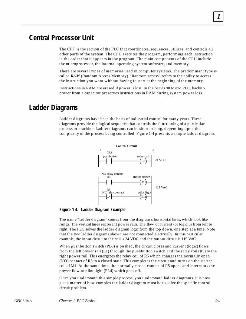
Ladder DiagramsLadder diagrams have been the basis of industrial control for many years. Thesediagrams provide the logical sequence that controls the functioning of a particularprocess or machine. Ladder diagrams can be short or long, depending upon thecomplexity of the process being controlled. Figure 1-4 presents a simple ladder diagram.
R5
PB3
R5
M1
R5NC relay contact pilot light
motor starter
relay coil
115 VAC
24 VDC
L1 L2
pushbutton
NO relay contact
Control Circuit
PL4
Figure 1-4. Ladder Diagram Example
The name “ladder diagram” comes from the diagram’s horizontal lines, which look likerungs. The vertical lines represent power rails. The flow of current (or logic) is from left toright. The PLC solves the ladder diagram logic from the top down, one step at a time. Notethat the two ladder diagrams shown are not connected electrically (In this particularexample, the input circuit to the coil is 24 VDC and the output circuit is 115 VAC.
When pushbutton switch (PB3) is pushed, the circuit closes and current (logic) flowsfrom the left power rail (L1) through the pushbutton switch and the relay coil (R5) to theright power rail. This energizes the relay coil of R5 which changes the normally open(NO) contact of R5 to a closed state. This completes the circuit and turns on the startercoil of M1. At the same time, the normally closed contact of R5 opens and interrupts thepower flow to pilot light (PL4) which goes off.
Once you understand this simple process, you understand ladder diagrams. It is nowjust a matter of how complex the ladder diagram must be to solve the specific controlcircuit problem.
2section level 1 figure bi level 1 table_big level 1
2-1GFK-1104A
Chapter 2 Basic PLC Application
When you complete this lesson, you will have:
� Reviewed a typical PLC application
� Reviewed a ladder diagram that can be created to perform the exampleapplication
PLC Application
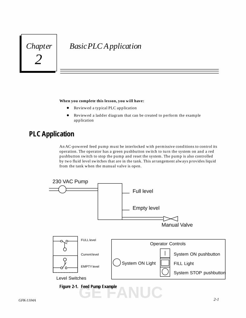
An AC-powered feed pump must be interlocked with permissive conditions to control itsoperation. The operator has a green pushbutton switch to turn the system on and a redpushbutton switch to stop the pump and reset the system. The pump is also controlledby two fluid level switches that are in the tank. This arrangement always provides liquidfrom the tank when the manual valve is open.
Full level
Empty level
Manual Valve
System ON Light FILL Light
System ON pushbutton
System STOP pushbutton
ÎÎÎÎÎÎÎÎÎÎÎÎÎÎÎÎÎÎÎÎ
EMPTY level
FULL level
Current level
Level Switches
230 VAC Pump
Operator Controls
Figure 2-1. Feed Pump Example
GE FANUC
2
2-2 Series 90� Micro Programmable Logic Controller Self-Teach Manual – May 1996 GFK-1104A
Ladder Diagram
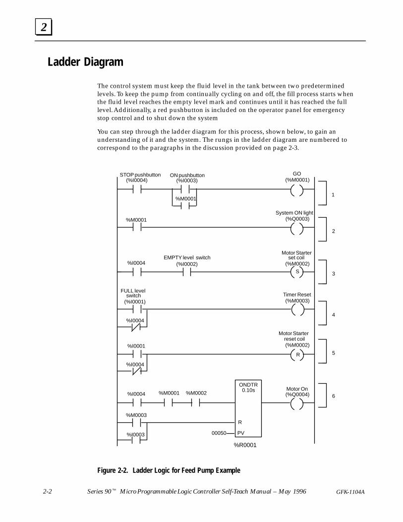
The control system must keep the fluid level in the tank between two predeterminedlevels. To keep the pump from continually cycling on and off, the fill process starts whenthe fluid level reaches the empty level mark and continues until it has reached the fulllevel. Additionally, a red pushbutton is included on the operator panel for emergencystop control and to shut down the system
You can step through the ladder diagram for this process, shown below, to gain anunderstanding of it and the system. The rungs in the ladder diagram are numbered tocorrespond to the paragraphs in the discussion provided on page 2-3.
STOP pushbutton GO
EMPTY level switch set coil
FULL levelswitch
Motor Starter
1
3
4
5
6
ON pushbutton
2
System ON light
S
reset coilMotor Starter
R
ONDTR
00050 PV
R
Timer Reset
(%I0004)
%I0004
%I0004
%I0004
(%I0003) (%M0001)
%M0001
%M0001
%M0001
(%Q0003)
(%I0002) (%M0002)
%M0002
(%M0002)
(%M0003)
%M0003
(%Q0004)Motor On
%I0003
(%I0001)
%I0001
%I0004
%R0001
0.10s
Figure 2-2. Ladder Logic for Feed Pump Example

2
2-3GFK-1104A Lesson 2 Basic PLC Application
Rung 1
Note
The STOP pushbutton switch is wired normally closed (NC) butprogrammed normally open (NO), so that the system will not start if theswitch fails. This is a safer arrangement than one using a NO switch. Inreal applications, a NC switch is usually used to provide an emergencystop switch.
In a real application, the emergency stop switch must be hardwired inthe equipment it is controlling. This precaution is necessary inaddition to providing the emergency stop function in the PLC logicprogram.
When the work day starts, the operator presses the ON pushbutton (%I0003) toactivate the system. Power flows through the normally closed STOP switch (%I0004)and the ON switch to the GO retentive coil (%M0001), energizing it and closing itsnormally open contacts. When the operator releases the ON pushbutton, powerflow is maintained to the %M0001 coil through the normally open contact %M0001(now closed).
This rung is sealed in by contact %M0001 because it remains energized as long as thesystem is on and the STOP pushbutton is not pressed. This is necessary because theON pushbutton is only closed momentarily, but the system must remain on until theSTOP pushbutton is pressed.
Rung 2
Contact %M0001 also energizes the System ON light (%Q0003).
Rung 3
When the current state of the system is that of Figure 2-1, the float on the EMPTYlevel switch (%I0002) rises, keeping the switch open with no current flowingthrough it. As the level of the water decreases, the EMPTY switch is energized. If theSTOP button is not pressed, the two conditions on this rung are met, and the MotorStarter set coil (%M0002) is energized. The set coil closes the %M0002 contacts inrung 6, satisfying one of the conditions for activating the on-delay timer (ONDTR)that controls the pump motor.
Note
Once it has received power, a set coil remains energized until thereference is reset by another coil. A set coil is used in this rung because,although the EMPTY switch will open when the pump comes on andcauses the fluid level in the tank to rise, we want the pump to continuerunning until the tank is full. Using a set coil is another way of sealingthe circuit.
GE FANUC
2
2-4 Series 90� Micro Programmable Logic Controller Self-Teach Manual – May 1996 GFK-1104A
Rungs 4 and 5
If either the STOP switch (%I0004) opens or the FULL level switch (%I0001) closes,the Timer Reset coil (%M0003) will be energized. Also, if either of these conditionsexists, power will flow to the Motor Starter reset coil, resetting the %M0002 contactsto an off (open) state.
Rung 6
This is the rung where the pump motor (%Q0004) is actually energized – if thefollowing conditions are met:
� STOP pushbutton is not pressed
� GO coil (%M0001) is energized
� Motor Starter coil (%M0002) is energized, and
� The ON pushbutton (%I0003) is not pressed
� Timer Reset coil (%M0003) is not energized.
An on-delay timer (ONDTR) is used to prevent the pump from startingunnecessarily if the EMPTY switch is accidentally closed for a very brief time. Thistimer increments while it receives power and holds its value when power flow stops.(The default time increment it tenths of a second.) When the ONDTR value equalsor exceeds the preset value (PV), its output is energized. The output remainsenergized until the ONDTR is reset (R).
When the ON pushbutton is pressed, %M0001 is energized. Because the circuit inrung 1 is sealed, %M0001 remains energized until the STOP pushbutton is pressed.When the EMPTY switch (%I0002) closes, %M0002 is set and power flows to theONDTR. In this example, the preset value is 00050 tenths of a second, or 5 seconds.When 5 seconds has elapsed, the ONDTR output is energized and power flows tothe Motor On coil (%Q0004).
When the FULL level switch closes, or the STOP pushbutton is pressed, %M0003 isenergized, resetting the ONDTR to a value of 0.
The ONDTR is also reset by pressing the ON pushbutton (%I0003). This is necessarybecause the ONDTR is retentive (it retains its value when power flow stops). Ifsystem power is lost while the pump is running, the ONDTR should be reset uponrestarting the system so that the pump does not start up unexpectedly.
There you have it – a ladder diagram program for a simple application. In subsequentlessons, you will find instructions for creating and testing this program. You also mightdiscover, on your own, ways to improve the logic by considering such things as:
� What if the EMPTY and FULL level switches are both stuck in the on position?
� Perhaps you could add another timer so that the pump will run for a minimumtime duration unless the FULL switch is activated.
� Could the application be accomplished more efficiently with fewer rungs orelements?
3section level 1 figure bi level 1 table_big level 1
3-1GFK-1104A
Chapter 3 Setup
In this lesson, you will find:
� A list of the equipment you need to complete Lessons 3 through 8
� Wiring information for your Series 90 Micro PLC
� Instructions for installing the Logicmaster 90 software on your PC
Getting Started
A. You will need the following items: (Refer to the User’s Manual (GFK-1065) forinformation about specific configurations).
� One of the following PLCs
14-Point DC In/Relay Out, AC Power IC693UDR001
DC In/Relay Out, DC Power IC693UDR002AC In/AC Out, AC Power IC693UAA003
28-Point DC In/1 DC and 11 Relay Out, AC Power IC693UDR005
AC In/AC Out, AC Power IC693UAA007
� Cable to connect the Series 90 Micro PLC to the computer serial port (included inSoftware and Cable Kit, IC640HWP300)
� A power cable (if using an AC unit), or a 24 VDC source (if using a DC unit)
� Logicmaster 90-30/20/Micro software or Logicmaster Micro software
B. To run Logicmaster 90 Micro software, you will need:
� An IBMTM-compatible PC with a hard disk:
� A Workmaster II industrial computer with a 101-key keyboard, or
� A personal computer with an Intel 80386 or higher processor, a minimum of2 Megabytes of memory, and at least 4 megabytes of free disk space
� MS-DOS� Version 5.0 or higher installed on your computer
Refer to the Logicmaster� 90 Series 90�-30/20/Micro Programming Software User’sManual (GFK-0466) for details concerning memory requirements.
C. An input device, such as described in “Input Switches” on page 3-2
TMIBM is a trademark of International Business Machines, Inc. �MS-DOS is a registeredtrademark of Microsoft Corporation.
GE FANUC
3
3-2 Series 90� Micro Programmable Logic Controller Self-Teach Manual – May 1996 GFK-1104A
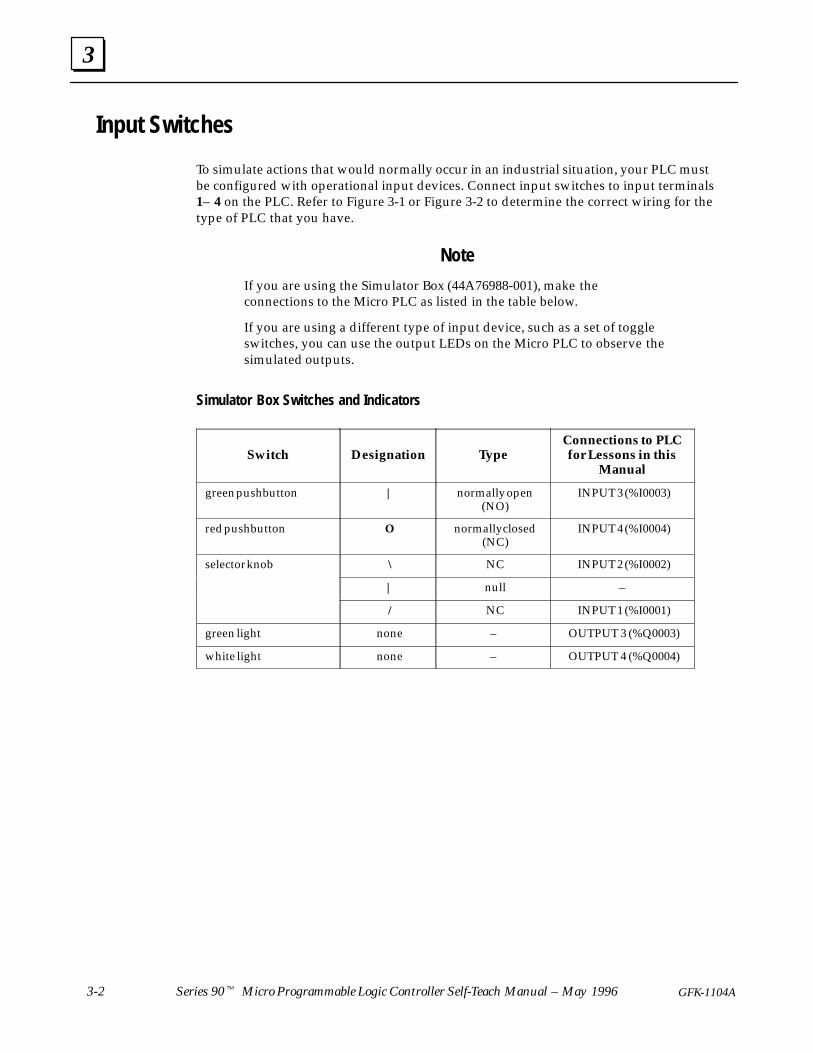
Input Switches
To simulate actions that would normally occur in an industrial situation, your PLC mustbe configured with operational input devices. Connect input switches to input terminals1– 4 on the PLC. Refer to Figure 3-1 or Figure 3-2 to determine the correct wiring for thetype of PLC that you have.
Note
If you are using the Simulator Box (44A76988-001), make theconnections to the Micro PLC as listed in the table below.
If you are using a different type of input device, such as a set of toggleswitches, you can use the output LEDs on the Micro PLC to observe thesimulated outputs.
Simulator Box Switches and Indicators
Switch Designation TypeConnections to PLCfor Lessons in this
Manual
green pushbutton | normally open(NO)
INPUT 3 (%I0003)
red pushbutton O normally closed(NC)
INPUT 4 (%I0004)
selector knob \ NC INPUT 2 (%I0002)
| null –
/ NC INPUT 1 (%I0001)
green light none – OUTPUT 3 (%Q0003)
white light none – OUTPUT 4 (%Q0004)
3
3-3GFK-1104A Lesson 3 Setup
Wire Connection Information
Wire connection information for power supply and I/O connections for Series 90 MicroPLCs is detailed below. Each terminal can accept solid or stranded wires, but the wiresinto any given terminal should be of the same type and size. Because of the small spacingbetween terminals, pay close attention when wiring stranded conductors. It is recommendedthat a crimp be applied to stranded wires.
Power Supply and I/O Connections
Use one AWG #14 (2.1 mm2) or two AWG #16 (1.3 mm2) copper conductors rated for75°C (167°F). The suggested torque for the terminal connections is 5 in-lbs (5.76 kg-cm).
General Wiring Practices
The following procedures should be followed when routing and connecting field wiringfrom user devices to the Series 90 Micro PLC inputs and outputs.
Warning
You should calculate the maximum current for each wire and observeproper wiring practices. Failure to do so may cause injury to personnelor damage to equipment.
� Turn off power to the Series 90 Micro PLC before connecting field wiring.
� All low level signal wires should be run separately from other field wiring.
� AC power wiring should be run separately from DC field wiring.
� Field wiring should not be routed close to any device that could be a potential sourceof electrical interference.
� If severe noise problems are present, additional power supply filtering or anisolation transformer may be required.
� Ensure that proper grounding procedures are followed to minimize potential safetyhazards to personnel.
� Label all wires to and from I/O devices.
Procedure for Power Connections� Use a three-wire power cable.
� The PC you will use for programming must be connected to the same power systemas the Series 90 Micro PLC.
� Power connections are located on the left, bottom side of the Series 90 Micro PLCcase.
GE FANUC
3
3-4 Series 90� Micro Programmable Logic Controller Self-Teach Manual – May 1996 GFK-1104A
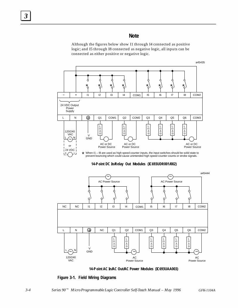
NoteAlthough the figures below show I1 through I4 connected as positivelogic; and I5 through I8 connected as negative logic, all inputs can beconnected as either positive or negative logic.
LOAD
AC or DCPower Source
AC or DCPower Source
** **
Q6Q1L N Q2 COM3
120/240
V
COM1
LOAD
COM2 Q5Q4Q3
* When I1 – I8 are used as high speed counter inputs, the input switches should be solid state toprevent bouncing which could cause unintended high speed counter counts or strobe signals.
AC or DCPower Source
** **
24 VDC Output
I1 I2 I3 I4 I5 I6 I7 I8COM1 COM2
a45435
or
~L N
24 VDC
SupplyPower
GND
VAC
LOAD
LOAD
LOAD
LOAD
14-P oint DC In/Relay Out Modules (IC693UDR001/002)
~ NL
120/240VAC
LOAD
ACPower Source
~
AC Power Source
Q6NCL N Q2 COM2
V
Q1 COM1 Q5Q4Q3
I1 I2 I3 I4 I5 I6 I7 I8COM1 COM2
a45444
ACPower Source
NC NC
AC Power Source
~
GND
LOAD
LOAD
LOAD
LOAD
LOAD
~
~
14-P oint AC In/AC Out/AC Power Modules (IC693UAA003)
Figure 3-1. Field Wiring Diagrams
3
3-5GFK-1104A Lesson 3 Setup
L O A D
L O A D
L O A D
L O A D
L O A D
L O A D
AC
or
DC
Pow
er
Sou
rce
AC
or
DC
Pow
er
Sou
rce
AC
or
DC
Pow
er
Sou
rce
AC
or
DC
Pow
er
Sou
rce
AC
or
DC
Pow
er
Sou
rce
~N
L
100/
240
VA
CA
C o
r D
CP
ower
Sou
rce
DC
Pow
er
Sup
ply
CO
M2
a454
14
I2I3
I4C
OM
1I5
I6I7
CO
M3
CO
M3
I10
I11
I12
CO
M4
I1
LN
Q1
Q2
Q3
Q4
Q5
CO
M1
Q6
CO
M2
CO
M3
Q7
Q8
CO
M4
CO
M5
Q9
GN
D VG
ND
CO
M4
Q10
I13
Q11
I14
I15
I16
24 V
DC
Pow
er
Sup
ply
I9
VC
CO
M6
Q12
CO
M7
CO
M7
I8
L O A D
L O A D
L O A D
L O A D
L O A D
L O A D
28-P
oint
DC
In/R
elay
Out
Mod
ules
(IC
696U
DR00
5)
Whe
n I1
–I8
are
used
as
high
spe
ed c
ount
er in
puts
, the
inpu
t sw
itche
s sh
ould
be
solid
sta
te to
prev
ent b
ounc
ing,
whi
ch c
ould
cau
se u
nint
ende
d co
unts
or s
trob
e si
gnal
s.
*
*
*
*
*
*
*
*
*
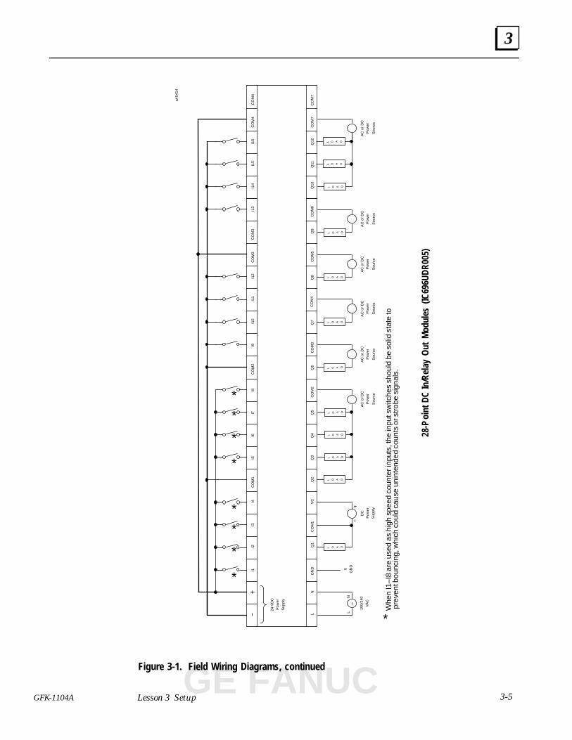
Figure 3-1. Field Wiring Diagrams, continued
GE FANUC
3
3-6 Series 90� Micro Programmable Logic Controller Self-Teach Manual – May 1996 GFK-1104A
28-P
oint
AC
In/A
C O
ut M
odul
es (I
C693
UAA0
07)
LN
100/
240
VA
C
AC
Pow
er S
ourc
e
CO
M4
Q9
Q10
Q11
Q12
~
~
a454
13
NC
NC
I2I3
I4C
OM
1I5
I6I7
I8C
OM
2C
OM
3C
OM
3I9
I10
I11
I12
CO
M4
I1
LN
NC
CO
M3
CO
M4
I13
I14
I15
I16
NC
NC
Q7
Q8
CO
M4
Q1
Q2
CO
M1
Q3
Q4
Q5
Q6
CO
M2
GN
D VG
ND
AC
Pow
er S
ourc
e
CO
M3
L O A D
L O A D
L O A D
L O A D
L O A D
L O A D
L O A D
L O A D
L O A D
L O A D
L O A D
L O A D
AC
Pow
er S
ourc
e
~
AC
Pow
er S
ourc
e
~
AC
Pow
er S
ourc
e
~
~
AC
Pow
er S
ourc
e
~
AC
Pow
er S
ourc
e
~
AC
Pow
er S
ourc
e
~
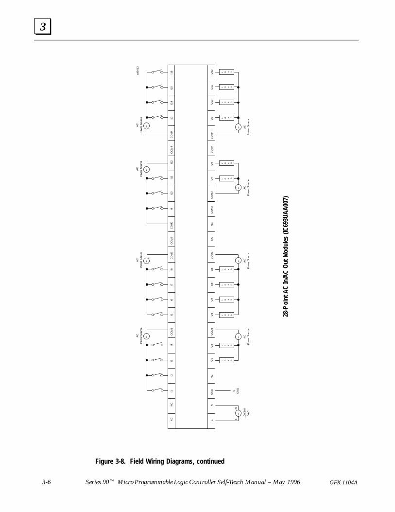
Figure 3-8. Field Wiring Diagrams, continued
3
3-7GFK-1104A Lesson 3 Setup
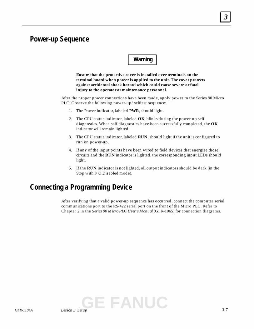
Power-up Sequence
Warning
Ensure that the protective cover is installed over terminals on theterminal board when power is applied to the unit. The cover protectsagainst accidental shock hazard which could cause severe or fatalinjury to the operator or maintenance personnel.
After the proper power connections have been made, apply power to the Series 90 MicroPLC. Observe the following power-up/self-test sequence:
1. The Power indicator, labeled PWR, should light.
2. The CPU status indicator, labeled OK, blinks during the power-up selfdiagnostics. When self-diagnostics have been successfully completed, the OKindicator will remain lighted.
3. The CPU status indicator, labeled RUN, should light if the unit is configured torun on power-up.
4. If any of the input points have been wired to field devices that energize thosecircuits and the RUN indicator is lighted, the corresponding input LEDs shouldlight.
5. If the RUN indicator is not lighted, all output indicators should be dark (in theStop with I/O Disabled mode).
Connecting a Programming Device
After verifying that a valid power-up sequence has occurred, connect the computer serialcommunications port to the RS-422 serial port on the front of the Micro PLC. Refer toChapter 2 in the Series 90 Micro PLC User’s Manual (GFK-1065) for connection diagrams.
GE FANUC
3
3-8 Series 90� Micro Programmable Logic Controller Self-Teach Manual – May 1996 GFK-1104A
Installing the Programming Software
1. Boot up the computer using MS-DOS. You should see the DOS prompt:
C:>
2. Be sure that CONFIG.SYS has files set to at least 20, i.e., FILES=20.
3. Remove write protection from the Logicmaster 90 Micro software disks. (Slidethe moveable tab on the diskette so that the hole is closed.)
4. Insert Logicmaster 90 Micro software disk #1 into the computer’s disk drive.
5. At the MS-DOS prompt, type the designation of the disk drive, followed by acolon. For example, if the disk is in drive A, type A: and press the Enter key.
6. To begin the automatic installation process, type INSTALL and press the Enterkey. Follow the instructions presented on the screen.
7. The INSTALL program prompts you to insert the other Logicmaster 90 Microdisks in the proper sequence. When all of the necessary files have been copied,the final installation screen will be displayed. When this happens, remove thefinal disk.
8. To complete the installation process, you must reboot the computer (pressControl-Alt-Del).
The automatic installation process creates one of the following directory structures onyour hard disk (C:)
Software Version Subdirectories Created
Standard serial communications \LM90\LM90\P30S\LM90\C30S
WSI \LM90\LM90\P30\LM90\C30
Refer to chapter 2 of the Logicmaster 90 Series 90-30/20/Micro Programming Software User’sManual (GFK-0466) for additional details concerning software installation.
4section level 1 figure bi level 1 table_big level 1
4-1GFK-1104A
Chapter 4 Basic Configuration
When you complete this lesson, you will have:
� Created a program folder
� Practiced running and stopping the Micro PLC
� Configured the Micro PLC using Logicmaster 90 Micro software
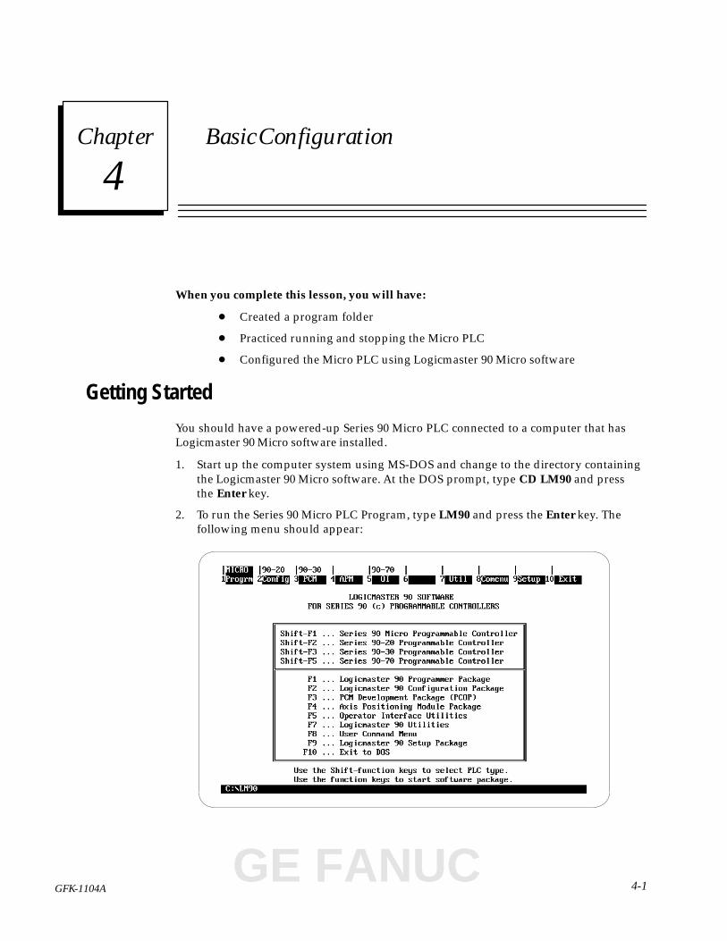
Getting Started
You should have a powered-up Series 90 Micro PLC connected to a computer that hasLogicmaster 90 Micro software installed.
1. Start up the computer system using MS-DOS and change to the directory containingthe Logicmaster 90 Micro software. At the DOS prompt, type CD LM90 and pressthe Enter key.
2. To run the Series 90 Micro PLC Program, type LM90 and press the Enter key. Thefollowing menu should appear:
GE FANUC
4
4-2 Series 90� Micro Programmable Logic Controller Self-Teach Manual – May 1996 GFK-1104A
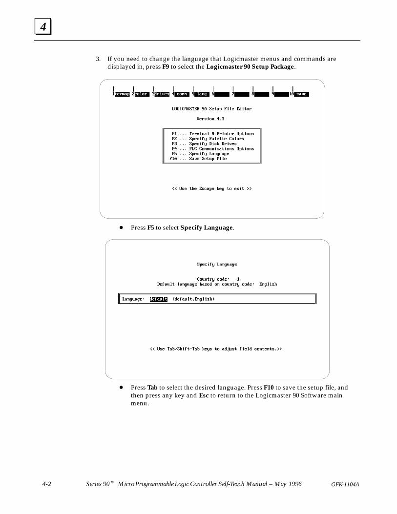
3. If you need to change the language that Logicmaster menus and commands aredisplayed in, press F9 to select the Logicmaster 90 Setup Package.
� Press F5 to select Specify Language.
� Press Tab to select the desired language. Press F10 to save the setup file, andthen press any key and Esc to return to the Logicmaster 90 Software mainmenu.
4
4-3GFK-1104A Lesson 4 Basic Configuration
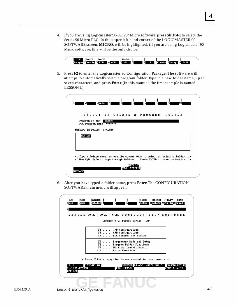
4. If you are using Logicmaster 90-30/20/Micro software, press Shift-F1 to select theSeries 90 Micro PLC. In the upper left-hand corner of the LOGICMASTER 90SOFTWARE screen, MICRO, will be highlighted. (If you are using Logicmaster 90Micro software, this will be the only choice.)
5. Press F2 to enter the Logicmaster 90 Configuration Package. The software willattempt to automatically select a program folder. Type in a new folder name, up toseven characters, and press Enter. (In this manual, the first example is namedLESSON1.)
6. After you have typed a folder name, press Enter. The CONFIGURATIONSOFTWARE main menu will appear.
GE FANUC

4
4-4 Series 90� Micro Programmable Logic Controller Self-Teach Manual – May 1996 GFK-1104A
Screen Elements
Figure 4-1 identifies the screen elements that are common to most of the screenspresented in the Logicmaster 90 Micro software. As you work with the software, theseareas provide useful information, such as system status and menu choices. (PLC Stateand Mode, within the Status Information area, are specifically pointed out in the figurebecause these features are used in the lessons in this manual.) For a more detaileddiscussion of the screen elements, refer to the Programming Software User’s Manual(GFK-0466).
Status Information
Function Key Assignments
Message Line
Menu Title
ModePLC State
Figure 4-1. Common Screen Elements
4
4-5GFK-1104A Lesson 4 Basic Configuration
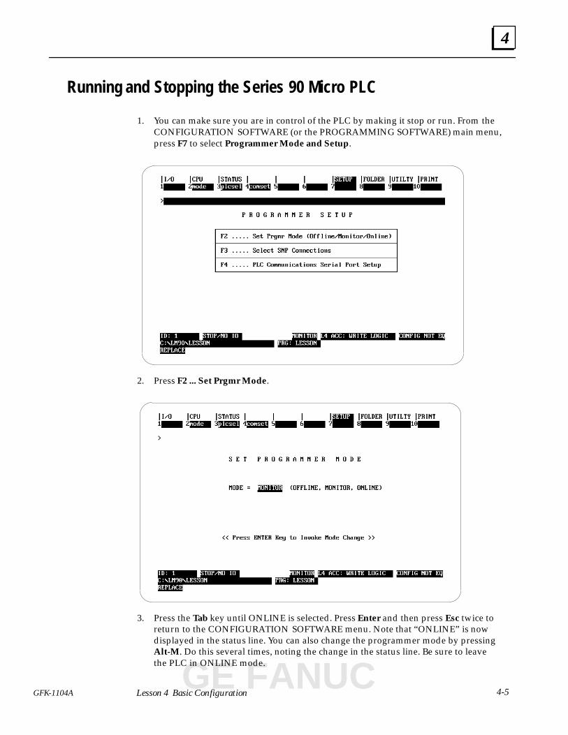
Running and Stopping the Series 90 Micro PLC
1. You can make sure you are in control of the PLC by making it stop or run. From theCONFIGURATION SOFTWARE (or the PROGRAMMING SOFTWARE) main menu,press F7 to select Programmer Mode and Setup.
2. Press F2 ... Set Prgmr Mode.
3. Press the Tab key until ONLINE is selected. Press Enter and then press Esc twice toreturn to the CONFIGURATION SOFTWARE menu. Note that “ONLINE” is nowdisplayed in the status line. You can also change the programmer mode by pressingAlt-M. Do this several times, noting the change in the status line. Be sure to leavethe PLC in ONLINE mode.
GE FANUC
4
4-6 Series 90� Micro Programmable Logic Controller Self-Teach Manual – May 1996 GFK-1104A
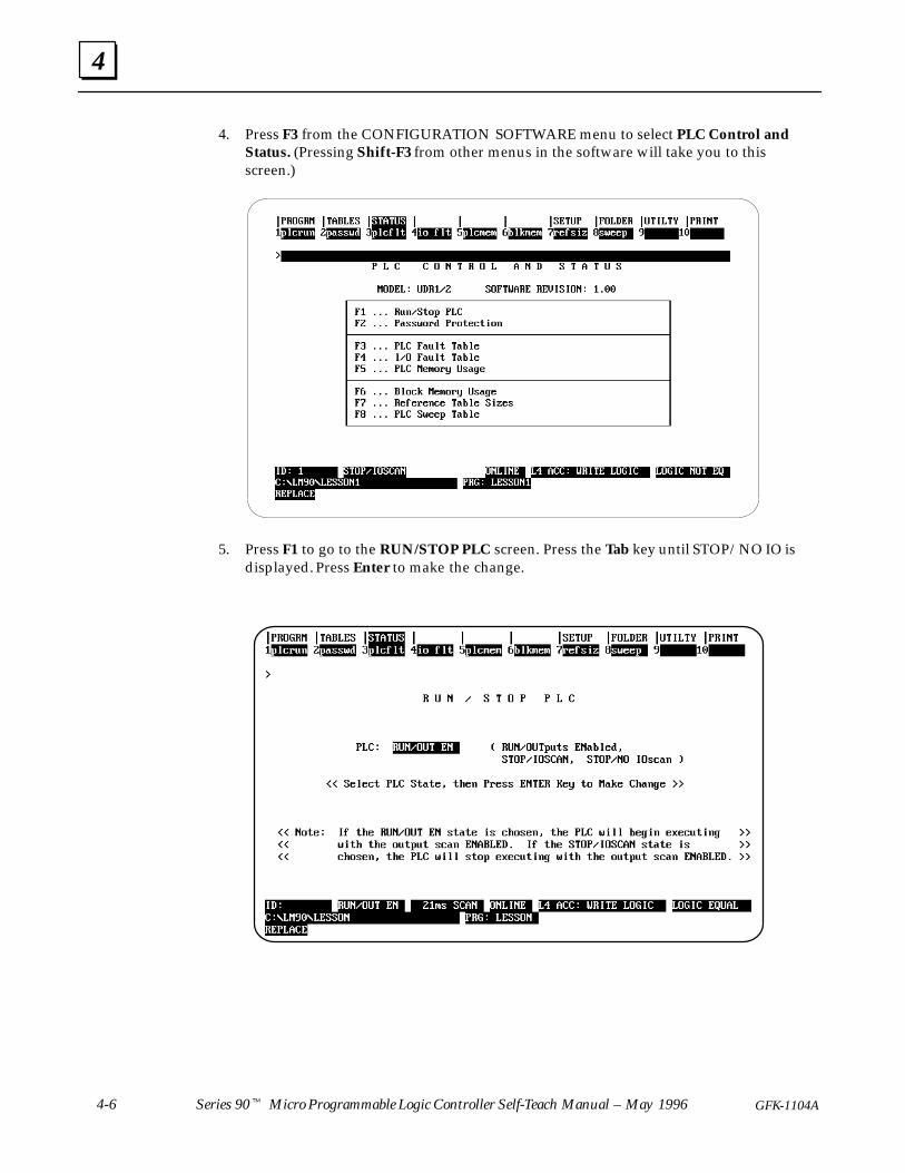
4. Press F3 from the CONFIGURATION SOFTWARE menu to select PLC Control andStatus. (Pressing Shift-F3 from other menus in the software will take you to thisscreen.)
5. Press F1 to go to the RUN/STOP PLC screen. Press the Tab key until STOP/NO IO isdisplayed. Press Enter to make the change.
4
4-7GFK-1104A Lesson 4 Basic Configuration
6. Note that PLC RUN/STOP status is displayed on the left side of the status line. PressEsc to return to the CONFIGURATION SOFTWARE menu.
7. You can also change the status of the PLC by pressing Alt-R. Do this several times,noting the change in the status line. You can also verify that the PLC actually togglesfrom RUN to STOP by watching the RUN LED on the front panel of the PLC go onand off.
8. When you are finished with this exercise, press Esc to return to theCONFIGURATION SOFTWARE main menu.
Alt-R and Alt-M are two of the key shortcuts that Logicmaster 90 Microsoftware provides. To see a complete list of these special key assignments, pressAlt-K. This list can be accessed from any screen in the software where the keyassignments are active. On these screens, the following message is displayed:<<Press Alt K at any time to see special key assignments>>
For contextual help, press Alt-H at any time. (You can try both of these keycombinations now.)
GE FANUC

4
4-8 Series 90� Micro Programmable Logic Controller Self-Teach Manual – May 1996 GFK-1104A
Configuring the Series 90 Micro PLC
Configuration is the process of selecting the operating parameters for the hardwaremodules in your system. Either configuration or programming can be done first.However, it is recommended that configuration be done before you create yourapplication program.
1. From the SOFTWARE CONFIGURATION main menu, press F1 to select I/OConfiguration. The following screen will appear.
2. If the correct catalog number and PLC model are not displayed at the top of theconfiguration screen, press F1 to select the CPU. When the following screen appears,use the ↑ and ↓ keys to select the type of Micro PLC that you have and then pressEnter. If you changed CPUs, the message “REPLACE displayed module? Y/N ”will appear. Press Y. The software will return you to the screen shown in step 1.
4
4-9GFK-1104A Lesson 4 Basic Configuration
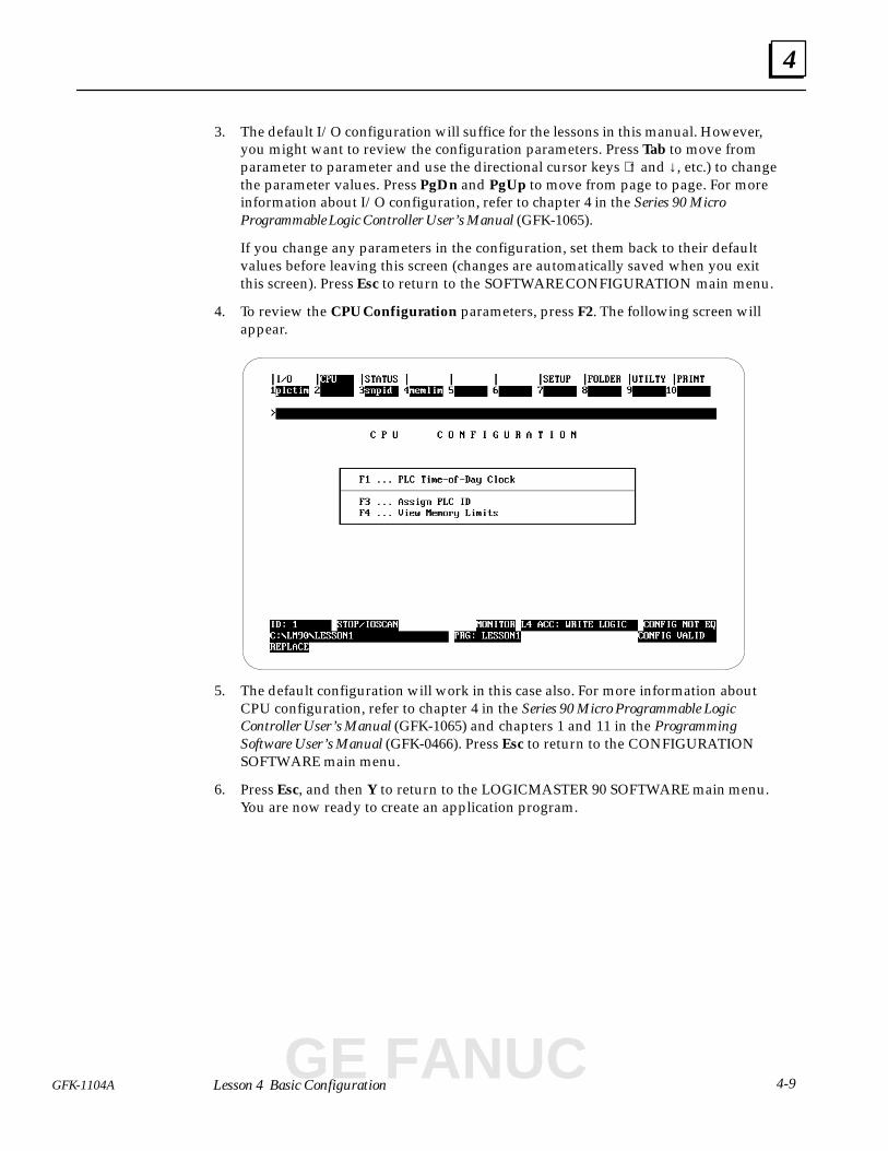
3. The default I/O configuration will suffice for the lessons in this manual. However,you might want to review the configuration parameters. Press Tab to move fromparameter to parameter and use the directional cursor keys ⟨↑ and ↓, etc.) to changethe parameter values. Press PgDn and PgUp to move from page to page. For moreinformation about I/O configuration, refer to chapter 4 in the Series 90 MicroProgrammable Logic Controller User’s Manual (GFK-1065).
If you change any parameters in the configuration, set them back to their defaultvalues before leaving this screen (changes are automatically saved when you exitthis screen). Press Esc to return to the SOFTWARE CONFIGURATION main menu.
4. To review the CPU Configuration parameters, press F2. The following screen willappear.
5. The default configuration will work in this case also. For more information aboutCPU configuration, refer to chapter 4 in the Series 90 Micro Programmable LogicController User’s Manual (GFK-1065) and chapters 1 and 11 in the ProgrammingSoftware User’s Manual (GFK-0466). Press Esc to return to the CONFIGURATIONSOFTWARE main menu.
6. Press Esc, and then Y to return to the LOGICMASTER 90 SOFTWARE main menu.You are now ready to create an application program.
GE FANUC
5section level 1 figure bi level 1 table_big level 1
5-1GFK-1104A
Chapter 5 Beginning Programming
When you complete this lesson, you will have:
� Created a one-rung ladder logic program.
� Downloaded the program to the PLC
� Tested the program
� Copied the program to a diskette
Getting Started
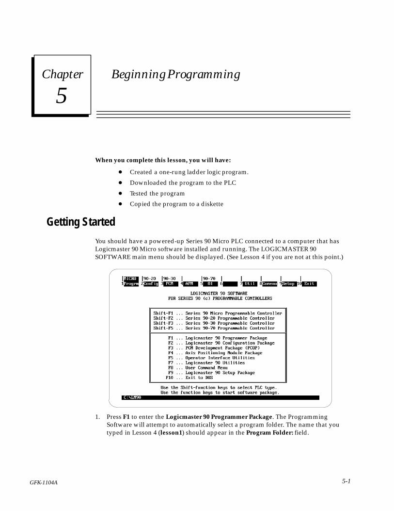
You should have a powered-up Series 90 Micro PLC connected to a computer that hasLogicmaster 90 Micro software installed and running. The LOGICMASTER 90SOFTWARE main menu should be displayed. (See Lesson 4 if you are not at this point.)
1. Press F1 to enter the Logicmaster 90 Programmer Package. The ProgrammingSoftware will attempt to automatically select a program folder. The name that youtyped in Lesson 4 (lesson1) should appear in the Program Folder: field.
5
5-2 Series 90� Micro Programmable Logic Controller Self-Teach Manual – May 1996 GFK-1104A
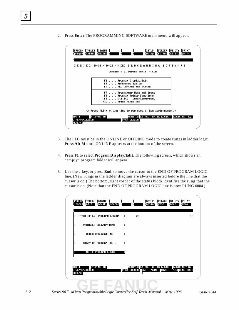
2. Press Enter. The PROGRAMMING SOFTWARE main menu will appear:
3. The PLC must be in the ONLINE or OFFLINE mode to create rungs in ladder logic.Press Alt-M until ONLINE appears at the bottom of the screen.
4. Press F1 to select Program Display/Edit. The following screen, which shows an“empty” program folder will appear:
5. Use the ↓ key, or press End, to move the cursor to the END OF PROGRAM LOGICline. (New rungs in the ladder diagram are always inserted before the line that thecursor is on.) The bottom, right corner of the status block identifies the rung that thecursor is on. (Note that the END OF PROGRAM LOGIC line is now RUNG 0004.)
GE FANUC
5
5-3GFK-1104A Lesson 5 Beginning Programming
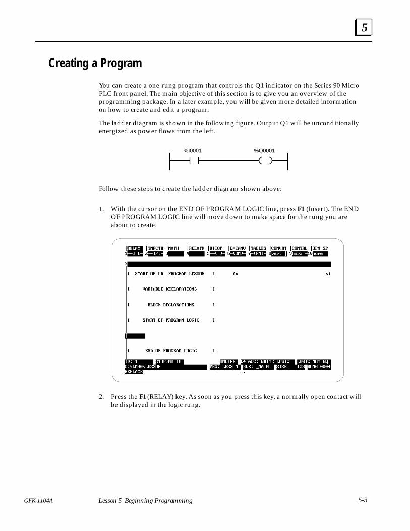
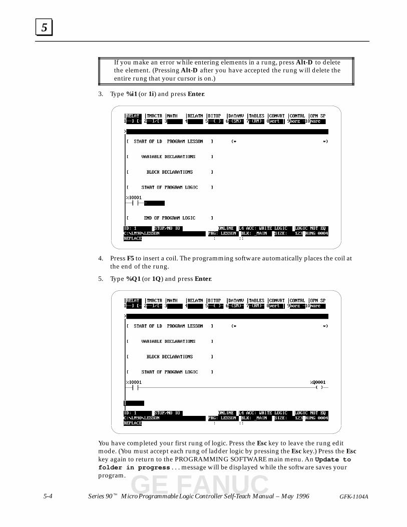
Creating a Program
You can create a one-rung program that controls the Q1 indicator on the Series 90 MicroPLC front panel. The main objective of this section is to give you an overview of theprogramming package. In a later example, you will be given more detailed informationon how to create and edit a program.
The ladder diagram is shown in the following figure. Output Q1 will be unconditionallyenergized as power flows from the left.
%Q0001%I0001
Follow these steps to create the ladder diagram shown above:
1. With the cursor on the END OF PROGRAM LOGIC line, press F1 (Insert). The ENDOF PROGRAM LOGIC line will move down to make space for the rung you areabout to create.
2. Press the F1 (RELAY) key. As soon as you press this key, a normally open contact willbe displayed in the logic rung.
5
5-4 Series 90� Micro Programmable Logic Controller Self-Teach Manual – May 1996 GFK-1104A
If you make an error while entering elements in a rung, press Alt-D to deletethe element. (Pressing Alt-D after you have accepted the rung will delete theentire rung that your cursor is on.)
3. Type %i1 (or 1i) and press Enter.
4. Press F5 to insert a coil. The programming software automatically places the coil atthe end of the rung.
5. Type %Q1 (or 1Q) and press Enter.
You have completed your first rung of logic. Press the Esc key to leave the rung editmode. (You must accept each rung of ladder logic by pressing the Esc key.) Press the Esckey again to return to the PROGRAMMING SOFTWARE main menu. An Update tofolder in progress . . . message will be displayed while the software saves yourprogram.
GE FANUC
5
5-5GFK-1104A Lesson 5 Beginning Programming
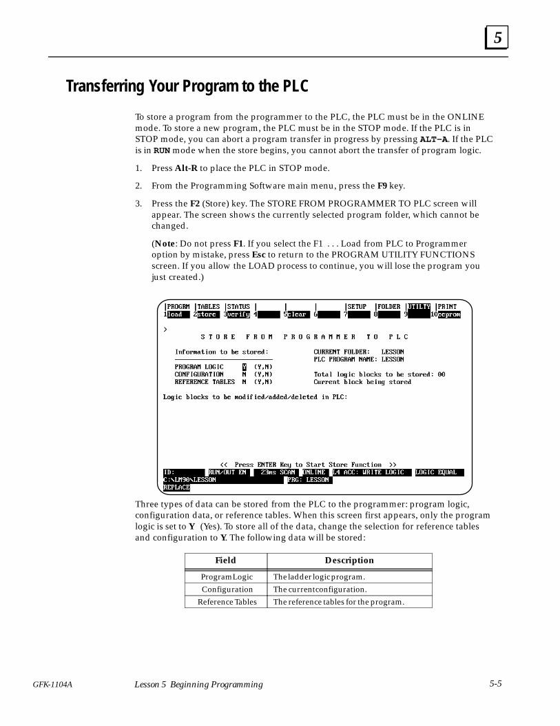
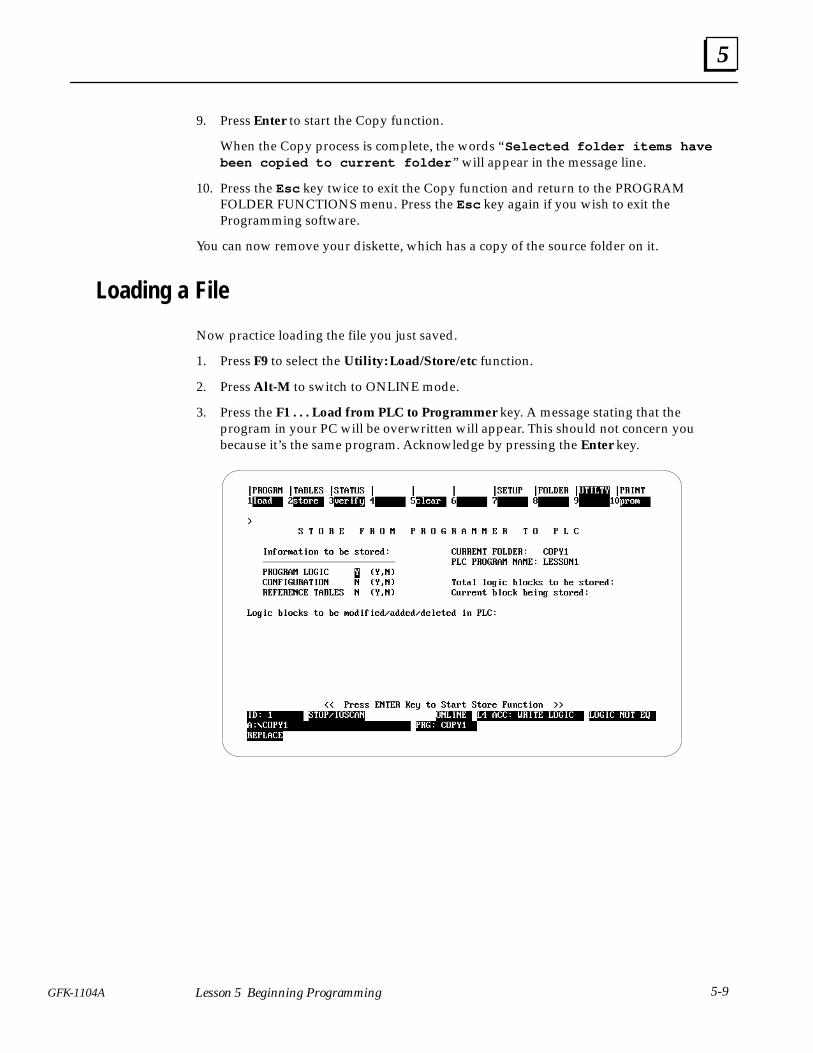
Transferring Your Program to the PLC
To store a program from the programmer to the PLC, the PLC must be in the ONLINEmode. To store a new program, the PLC must be in the STOP mode. If the PLC is inSTOP mode, you can abort a program transfer in progress by pressing ALT-A . If the PLCis in RUN mode when the store begins, you cannot abort the transfer of program logic.
1. Press Alt-R to place the PLC in STOP mode.
2. From the Programming Software main menu, press the F9 key.
3. Press the F2 (Store) key. The STORE FROM PROGRAMMER TO PLC screen willappear. The screen shows the currently selected program folder, which cannot bechanged.
(Note: Do not press F1. If you select the F1 . . . Load from PLC to Programmeroption by mistake, press Esc to return to the PROGRAM UTILITY FUNCTIONSscreen. If you allow the LOAD process to continue, you will lose the program youjust created.)
Three types of data can be stored from the PLC to the programmer: program logic,configuration data, or reference tables. When this screen first appears, only the programlogic is set to Y (Yes). To store all of the data, change the selection for reference tablesand configuration to Y. The following data will be stored:
Field Description
Program Logic The ladder logic program.
Configuration The current configuration.
Reference Tables The reference tables for the program.
5
5-6 Series 90� Micro Programmable Logic Controller Self-Teach Manual – May 1996 GFK-1104A
4. Press Enter to start the Store function. The following messages will be displayed:
Program name in PLC does not match program name in folder: continue? Y/N
5. Press Y. The following message will be displayed:
Selected items will be overwritten; continue to store to PLC? Y/N
In each case, press Y to continue the store process. The following message will bedisplayed:
Storing selected items to PLC . . . (Press ALT-A to abort)
After a successful transfer of data, the software displays the message “StoreComplete ” at the top of the screen, and “LOGIC EQUAL” in the status block. If acommunication or disk error occurs during the store process (indicated by a messageon the screen), the selected items are cleared from the current folder. Correct theerror and repeat the store function.
Running Your Program
1. Press Shift-F1 to return to the PROGRAM DISPLAY/EDIT screen.
2. Make sure the PLC is in the RUN mode. (Press Alt-R to put the PLC in the RUNmode.) “RUN/OUT EN” will appear in the status block on the screen and the RUNindicator on the PLC will light.
3. On your input device, turn on the switch that is wired to Input 1. The Input 1 andOutput 1 LEDs on the front of the Series 90 Micro PLC will light. As you turn theswitch on and off, observe the ladder diagram. The contact and coil symbols will behighlighted when the input switch is on.
GE FANUC
5
5-7GFK-1104A Lesson 5 Beginning Programming
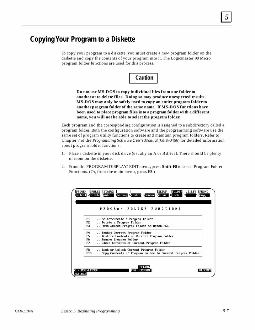
Copying Your Program to a Diskette
To copy your program to a diskette, you must create a new program folder on thediskette and copy the contents of your program into it. The Logicmaster 90 Microprogram folder functions are used for this process.
Caution
Do not use MS-DOS to copy individual files from one folder toanother or to delete files. Doing so may produce unexpected results.MS-DOS may only be safely used to copy an entire program folder toanother program folder of the same name. If MS-DOS functions havebeen used to place program files into a program folder with a differentname, you will not be able to select the program folder.
Each program and the corresponding configuration is assigned to a subdirectory called aprogram folder. Both the configuration software and the programming software use thesame set of program utility functions to create and maintain program folders. Refer toChapter 7 of the Programming Software User’s Manual (GFK-0466) for detailed informationabout program folder functions.
1. Place a diskette in your disk drive (usually an A or B drive). There should be plentyof room on the diskette.
2. From the PROGRAM DISPLAY/EDIT menu, press Shift-F8 to select Program FolderFunctions. (Or, from the main menu, press F8.)
5
5-8 Series 90� Micro Programmable Logic Controller Self-Teach Manual – May 1996 GFK-1104A
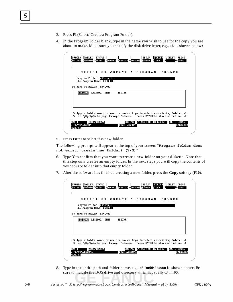
3. Press F1 (Select/Create a Program Folder).
4. In the Program Folder blank, type in the name you wish to use for the copy you areabout to make. Make sure you specify the disk drive letter, e.g., a:\ as shown below:
5. Press Enter to select this new folder.
The following prompt will appear at the top of your screen: “Program folder doesnot exist; create new folder? (Y/N) ”
6. Type Y to confirm that you want to create a new folder on your diskette. Note thatthis step only creates an empty folder. In the next steps you will copy the contents ofyour source folder into that empty folder.
7. After the software has finished creating a new folder, press the Copy softkey (F10).
8. Type in the entire path and folder name, e.g., c:\lm90\lesson1 as shown above. Besure to include the DOS drive and directory which is usually c:\lm90.
GE FANUC
5
5-9GFK-1104A Lesson 5 Beginning Programming
9. Press Enter to start the Copy function.
When the Copy process is complete, the words “Selected folder items havebeen copied to current folder ” will appear in the message line.
10. Press the Esc key twice to exit the Copy function and return to the PROGRAMFOLDER FUNCTIONS menu. Press the Esc key again if you wish to exit theProgramming software.
You can now remove your diskette, which has a copy of the source folder on it.
Loading a File
Now practice loading the file you just saved.
1. Press F9 to select the Utility: Load/Store/etc function.
2. Press Alt-M to switch to ONLINE mode.
3. Press the F1 . . . Load from PLC to Programmer key. A message stating that theprogram in your PC will be overwritten will appear. This should not concern youbecause it’s the same program. Acknowledge by pressing the Enter key.
6section level 1 figure bi level 1 table_big level 1
6-1GFK-1104A
Chapter 6 More Programming
When you have completed this lesson, you will have learned how to:
� Clear the memory of the programmer� Develop the logic for a simple application.
� Enter the logic into the programmer package
� Edit your program.
� Label (name) the elements of your program.
� Search for a reference address within your program.
In this lesson, you will create the example program described in Lesson 2 and thenmodify it so that you can practice with the programmer package. Before proceeding,review the ladder diagram on page 2-2.
NoteThe ladder diagram created in this lesson is designed to help you understand how toprogram the Series 90 Micro PLC. Therefore it lacks some safety interlocks that arenecessary in an actual application.
Getting StartedYou should have a powered-up Series 90 Micro PLC connected to a computer that hasLogicmaster 90 Micro software installed and running. The PROGRAMMINGSOFTWARE main menu, shown below, should be displayed. (See Lesson 5 if you are notat this point.)
GE FANUC

6
6-2 Series 90� Micro Programmable Logic Controller Self-Teach Manual – May 1996 GFK-1104A
Clearing Memory
If you have been following the lessons in order, you probably have a program stored inthe programmer memory.
1. Press F9 to select the Utility: Load/Store/etc function.
2. Press the F5 . . . Clear PLC Memory key. The following screen will appear:
3. Press the Enter key to start the clear function. The following prompt will appear inthe message line:
Current PLC contents will be lost; continue clear? (Y/N)
4. Press Y. The message, Clearing selected memory in PLC .... , will bedisplayed while the program in the PLC is being cleared.
5. When the Clear complete message appears, press Esc twice to return to thePROGRAMMING SOFTWARE main menu.
6
6-3GFK-1104A Lesson 6 More Programming
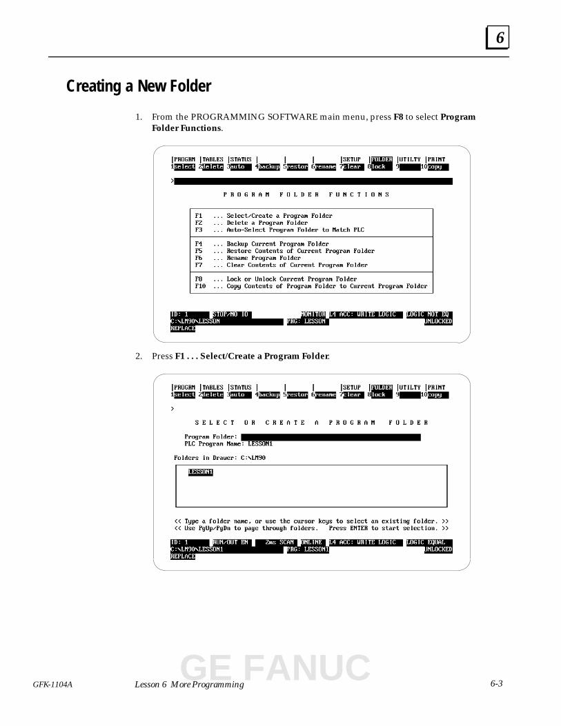
Creating a New Folder
1. From the PROGRAMMING SOFTWARE main menu, press F8 to select ProgramFolder Functions.
2. Press F1 . . . Select/Create a Program Folder.
GE FANUC
6
6-4 Series 90� Micro Programmable Logic Controller Self-Teach Manual – May 1996 GFK-1104A
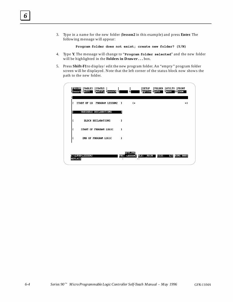
3. Type in a name for the new folder (lesson2 in this example) and press Enter. Thefollowing message will appear:
Program folder does not exist; create new folder? (Y/N)
4. Type Y. The message will change to “Program folder selected ” and the new folderwill be highlighted in the Folders in Drawer . . . box.
5. Press Shift-F1 to display/edit the new program folder. An “empty” program folderscreen will be displayed. Note that the left corner of the status block now shows thepath to the new folder.
6
6-5GFK-1104A Lesson 6 More Programming
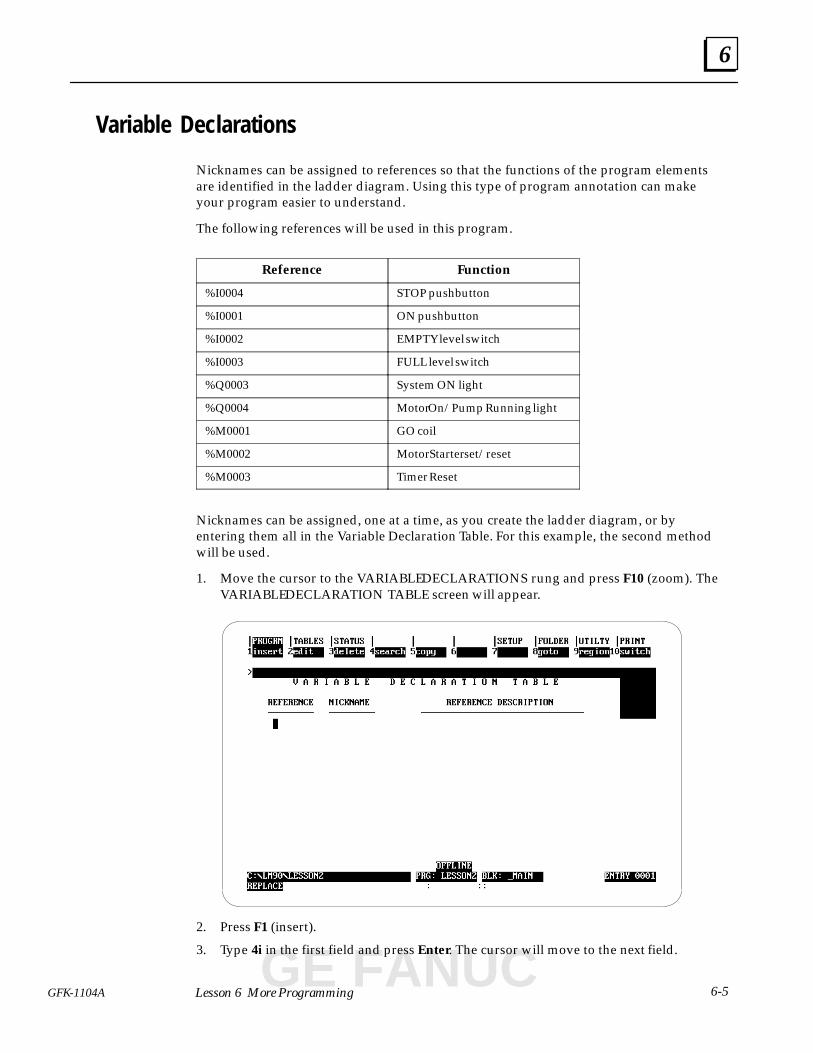
Variable Declarations
Nicknames can be assigned to references so that the functions of the program elementsare identified in the ladder diagram. Using this type of program annotation can makeyour program easier to understand.
The following references will be used in this program.
Reference Function
%I0004 STOP pushbutton
%I0001 ON pushbutton
%I0002 EMPTY level switch
%I0003 FULL level switch
%Q0003 System ON light
%Q0004 Motor On/Pump Running light
%M0001 GO coil
%M0002 Motor Starter set/reset
%M0003 Timer Reset
Nicknames can be assigned, one at a time, as you create the ladder diagram, or byentering them all in the Variable Declaration Table. For this example, the second methodwill be used.
1. Move the cursor to the VARIABLE DECLARATIONS rung and press F10 (zoom). TheVARIABLE DECLARATION TABLE screen will appear.
2. Press F1 (insert).
3. Type 4i in the first field and press Enter. The cursor will move to the next field.
GE FANUC
6
6-6 Series 90� Micro Programmable Logic Controller Self-Teach Manual – May 1996 GFK-1104A
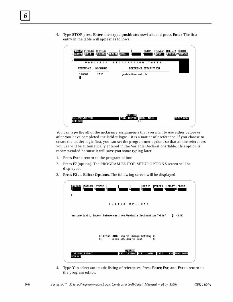
4. Type STOP, press Enter; then type pushbutton switch, and press Enter. The firstentry in the table will appear as follows:
You can type the all of the nickname assignments that you plan to use either before orafter you have completed the ladder logic – it is a matter of preference. If you choose tocreate the ladder logic first, you can set the programmer options so that all the referencesyou use will be automatically entered in the Variable Declarations Table. This option isrecommended because it will save you some typing later.
1. Press Esc to return to the program editor.
2. Press F7 (option). The PROGRAM EDITOR SETUP OPTIONS screen will bedisplayed.
3. Press F2 . . . Editor Options. The following screen will be displayed:
4. Type Y to select automatic listing of references. Press Enter, Esc, and Esc to return tothe program editor.
6
6-7GFK-1104A Lesson 6 More Programming
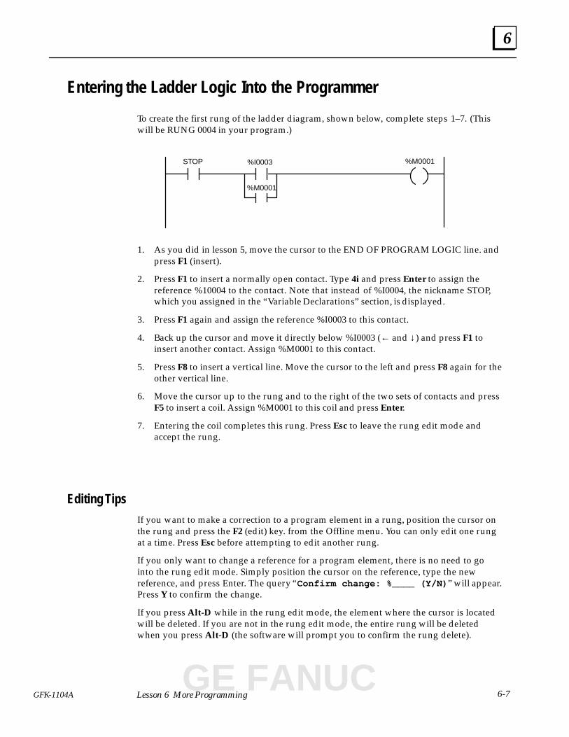
Entering the Ladder Logic Into the Programmer
To create the first rung of the ladder diagram, shown below, complete steps 1–7. (Thiswill be RUNG 0004 in your program.)
%I0003 %M0001
%M0001
STOP
1. As you did in lesson 5, move the cursor to the END OF PROGRAM LOGIC line. andpress F1 (insert).
2. Press F1 to insert a normally open contact. Type 4i and press Enter to assign thereference %10004 to the contact. Note that instead of %I0004, the nickname STOP,which you assigned in the “Variable Declarations” section, is displayed.
3. Press F1 again and assign the reference %I0003 to this contact.
4. Back up the cursor and move it directly below %I0003 (← and ↓ ) and press F1 toinsert another contact. Assign %M0001 to this contact.
5. Press F8 to insert a vertical line. Move the cursor to the left and press F8 again for theother vertical line.
6. Move the cursor up to the rung and to the right of the two sets of contacts and pressF5 to insert a coil. Assign %M0001 to this coil and press Enter.
7. Entering the coil completes this rung. Press Esc to leave the rung edit mode andaccept the rung.
Editing Tips
If you want to make a correction to a program element in a rung, position the cursor onthe rung and press the F2 (edit) key. from the Offline menu. You can only edit one rungat a time. Press Esc before attempting to edit another rung.
If you only want to change a reference for a program element, there is no need to gointo the rung edit mode. Simply position the cursor on the reference, type the newreference, and press Enter. The query “Confirm change: %____ (Y/N) ” will appear.Press Y to confirm the change.
If you press Alt-D while in the rung edit mode, the element where the cursor is locatedwill be deleted. If you are not in the rung edit mode, the entire rung will be deletedwhen you press Alt-D (the software will prompt you to confirm the rung delete).
GE FANUC
6
6-8 Series 90� Micro Programmable Logic Controller Self-Teach Manual – May 1996 GFK-1104A
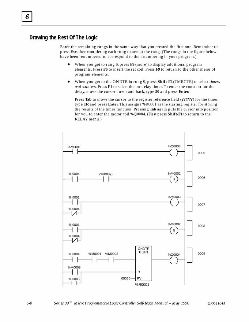
Drawing the Rest Of The Logic
Enter the remaining rungs in the same way that you created the first one. Remember topress Esc after completing each rung to accept the rung. (The rungs in the figure belowhave been renumbered to correspond to their numbering in your program.)
� When you get to rung 6, press F9 (more) to display additional programelements. Press F6 to insert the set coil. Press F9 to return to the other menu ofprogram elements.
� When you get to the ONDTR in rung 9, press Shift-F2 (TMRCTR) to select timersand counters. Press F1 to select the on-delay timer. To enter the constant for thedelay, move the cursor down and back, type 50 and press Enter.
Press Tab to move the cursor to the register reference field (??????) for the timer,type 1R and press Enter. This assigns %R0001 as the starting register for storingthe results of the timer function. Pressing Tab again puts the cursor into positionfor you to enter the motor coil %Q0004. (First press Shift-F1 to return to theRELAY menu.)
S
R
ONDTR
00050 PV
R
%M0001
%M0001
%Q0003
(%I0002) %M0002
%M0002
%M0002
%M0003
%M0003
%Q0004
%I0003
%I0001
%I0001
%I0004
%I0004
%I0004
%R0001
0005
0006
0007
0008
0009
%I0004
0.10s
6
6-9GFK-1104A Lesson 6 More Programming
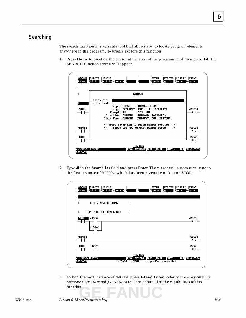
Searching
The search function is a versatile tool that allows you to locate program elementsanywhere in the program. To briefly explore this function:
1. Press Home to position the cursor at the start of the program, and then press F4. TheSEARCH function screen will appear.
2. Type 4i in the Search for field and press Enter. The cursor will automatically go tothe first instance of %I0004, which has been given the nickname STOP.
3. To find the next instance of %I0004, press F4 and Enter. Refer to the ProgrammingSoftware User’s Manual (GFK-0466) to learn about all of the capabilities of thisfunction.
GE FANUC
6
6-10 Series 90� Micro Programmable Logic Controller Self-Teach Manual – May 1996 GFK-1104A
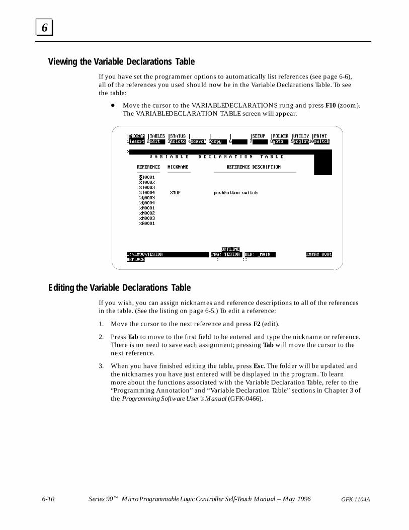
Viewing the Variable Declarations Table
If you have set the programmer options to automatically list references (see page 6-6),all of the references you used should now be in the Variable Declarations Table. To seethe table:
� Move the cursor to the VARIABLE DECLARATIONS rung and press F10 (zoom).The VARIABLE DECLARATION TABLE screen will appear.
Editing the Variable Declarations Table
If you wish, you can assign nicknames and reference descriptions to all of the referencesin the table. (See the listing on page 6-5.) To edit a reference:
1. Move the cursor to the next reference and press F2 (edit).
2. Press Tab to move to the first field to be entered and type the nickname or reference.There is no need to save each assignment; pressing Tab will move the cursor to thenext reference.
3. When you have finished editing the table, press Esc. The folder will be updated andthe nicknames you have just entered will be displayed in the program. To learnmore about the functions associated with the Variable Declaration Table, refer to the“Programming Annotation” and “Variable Declaration Table” sections in Chapter 3 ofthe Programming Software User’s Manual (GFK-0466).

6
6-11GFK-1104A Lesson 6 More Programming
Testing Your Program
1. Store your program to the PLC (If you don’t remember how to do this, review“Transferring Your Program to the PLC” on page 5-5.)
Note: Variable declarations are not stored in the PLC.
2. With your program displayed (in the PROGRAM DISPLAY/EDIT screen), make surethe PLC is in the RUN mode. (Press Alt-R to put the PLC in the RUN mode.)“RUN/OUT EN” will appear in the status block on the screen and the RUN indicatoron the PLC will light.
3. Operate the switches on your input device to simulate the operation of the pumpingsystem.
� On your input device, toggle the ON switch. The GO coil (%M0001) should behighlighted in the ladder diagram and the System On output indicator (Q3) onthe PLC should light.
� Toggle the EMPTY switch. The timer should start counting. After 5 seconds, theMotor On output (Q4) indicator on the PLC should light.
� Toggle the FULL switch. The on-delay timer should reset and the Motor Onoutput indicator (Q4) should go off.
� Toggle the STOP switch. The System On output indicator (Q3) should go off.
� Experiment by activating the control switches in different sequences to verifythat your pumping system is operating properly.
GE FANUC
7section level 1 figure bi level 1 table_big level 1
7-1GFK-1104A
Chapter 7 Data Monitoring
When you complete this lesson you will have learned how to:
� View the different types of data tables.
� Change values in the data tables.
� Create a mixed table to view the contents of different types of references at thesame time
This lesson presents an overview of the data tables. For more information, refer toChapter 5 of the Programming Software User’s Manual (GFK–0466).
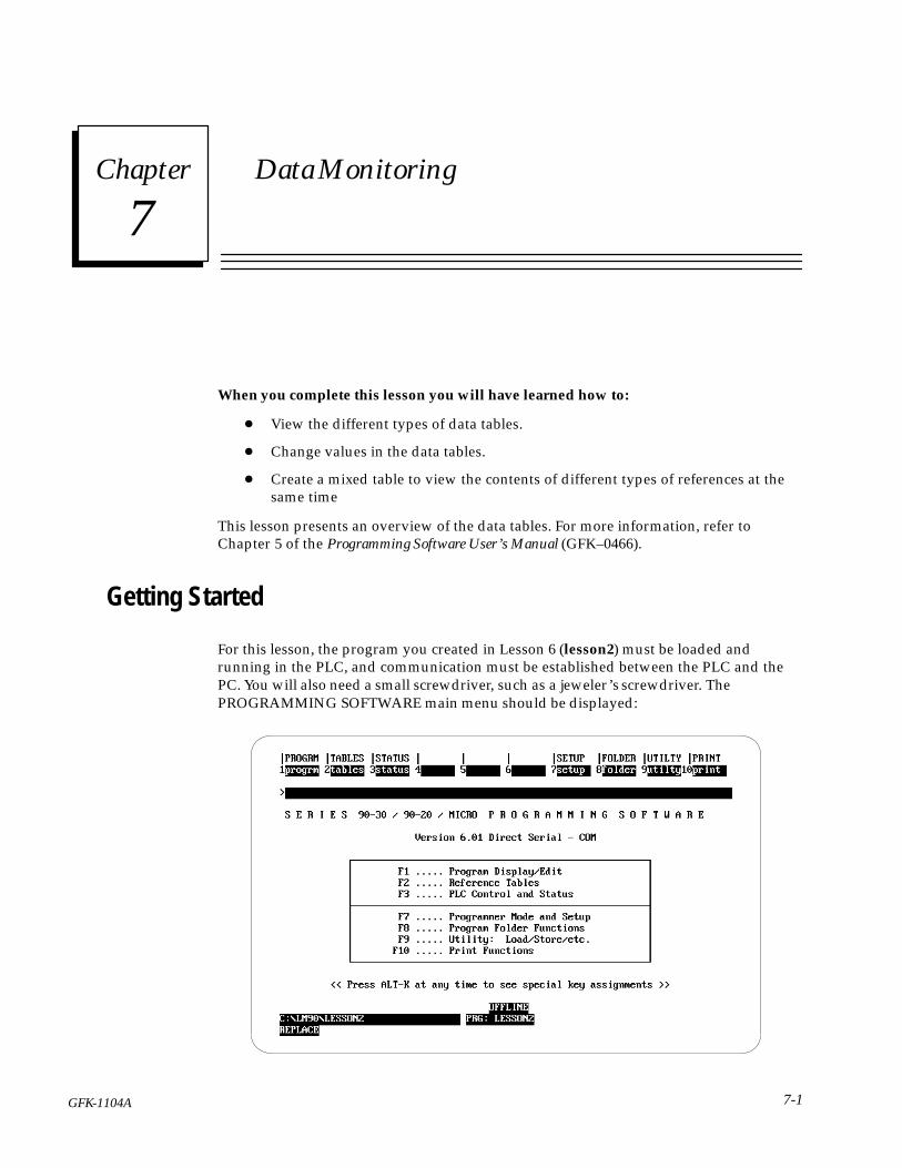
Getting Started
For this lesson, the program you created in Lesson 6 (lesson2) must be loaded andrunning in the PLC, and communication must be established between the PLC and thePC. You will also need a small screwdriver, such as a jeweler’s screwdriver. ThePROGRAMMING SOFTWARE main menu should be displayed:
7
7-2 Series 90� Micro Programmable Logic Controller Self-Teach Manual – May 1996 GFK-1104A
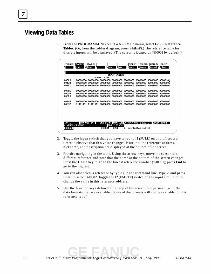
Viewing Data Tables
1. From the PROGRAMMING SOFTWARE Main menu, select F2 . . . ReferenceTables. (Or, from the ladder diagram, press Shift-F2.) The reference table fordiscrete inputs will be displayed. (The cursor is located on %I0001 by default.)
2. Toggle the input switch that you have wired to I1 (FULL) on and off severaltimes to observe that this value changes. Note that the reference address,nickname, and description are displayed at the bottom of the screen.
3. Practice navigating in the table. Using the arrow keys, move the cursor to adifferent reference and note that the name at the bottom of the screen changes.Press the Home key to go to the lowest reference number (%I0001); press End togo to the highest.
4. You can also select a reference by typing in the command line. Type 2i and pressEnter to select %I0002. Toggle the I2 (EMPTY) switch on the input simulator tochange the value in this reference address.
5. Use the function keys defined at the top of the screen to experiment with thedata formats that are available. (Some of the formats will not be available for thisreference type.)
GE FANUC
7
7-3GFK-1104A Lesson 7 Data Monitoring
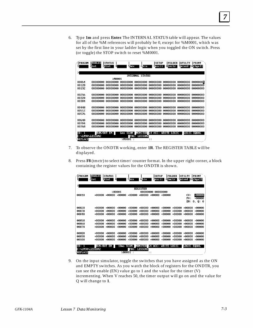
6. Type 1m and press Enter. The INTERNAL STATUS table will appear. The valuesfor all of the %M references will probably be 0, except for %M0001, which wasset by the first line in your ladder logic when you toggled the ON switch. Press(or toggle) the STOP switch to reset %M0001.
7. To observe the ONDTR working, enter 1R. The REGISTER TABLE will bedisplayed.
8. Press F8 (tmctr) to select timer/counter format. In the upper right corner, a blockcontaining the register values for the ONDTR is shown.
9. On the input simulator, toggle the switches that you have assigned as the ONand EMPTY switches. As you watch the block of registers for the ONDTR, youcan see the enable (EN) value go to 1 and the value for the timer (V)incrementing. When V reaches 50, the timer output will go on and the value forQ will change to 1.
7
7-4 Series 90� Micro Programmable Logic Controller Self-Teach Manual – May 1996 GFK-1104A
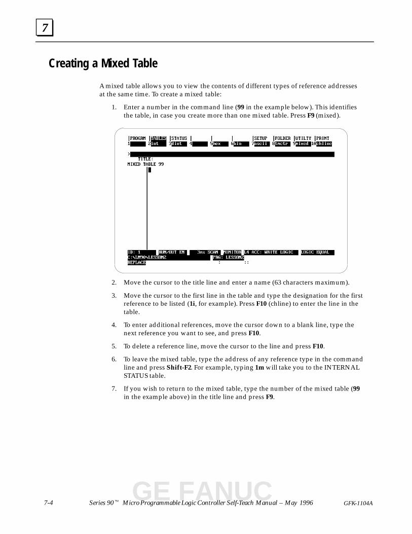
Creating a Mixed Table
A mixed table allows you to view the contents of different types of reference addressesat the same time. To create a mixed table:
1. Enter a number in the command line (99 in the example below). This identifiesthe table, in case you create more than one mixed table. Press F9 (mixed).
2. Move the cursor to the title line and enter a name (63 characters maximum).
3. Move the cursor to the first line in the table and type the designation for the firstreference to be listed (1i, for example). Press F10 (chline) to enter the line in thetable.
4. To enter additional references, move the cursor down to a blank line, type thenext reference you want to see, and press F10.
5. To delete a reference line, move the cursor to the line and press F10.
6. To leave the mixed table, type the address of any reference type in the commandline and press Shift-F2. For example, typing 1m will take you to the INTERNALSTATUS table.
7. If you wish to return to the mixed table, type the number of the mixed table (99in the example above) in the title line and press F9.
GE FANUC
7
7-5GFK-1104A Lesson 7 Data Monitoring
Viewing %AI References
Two potentiometers, located on the front panel of the Micro PLC, allow you to manuallyset input values that are stored in %AI16 and %AI17. The top potentiometer controls%AI16, and the bottom one controls %AI17.
Analog Potentiometer Input Filtering Control
Due to the nature of analog input, the values seen in %AI16 and %AI17 will have somefluctuation. This variation could make these inputs unusable for some applications. TheSeries 90 Micro PLC uses an averaging filter to stabilize these inputs.
The filter used on %AI16 and %AI17 samples the values on these inputs once per sweep.When a predetermined number of samples has been read, it averages them and storesthe result in %AI16 and %AI17.
To control the number of samples to average, you can adjust the value in memoryreference %AQ1. The value in %AQ1 represents 2%AQ1 samples. For example, if 4 isplaced in %AQ1, 16 samples will be taken and averaged to determine the values to placein %AI16 and %AI17.
Any value can be placed in %AQ1, however, only the lower 3 bits of %AQ1 arerecognized, giving a minimum value of 0 and a maximum value of 7 (for 0–128samples). By default, 16 samples are averaged (equivalent to a value of 4 in %AQ1).
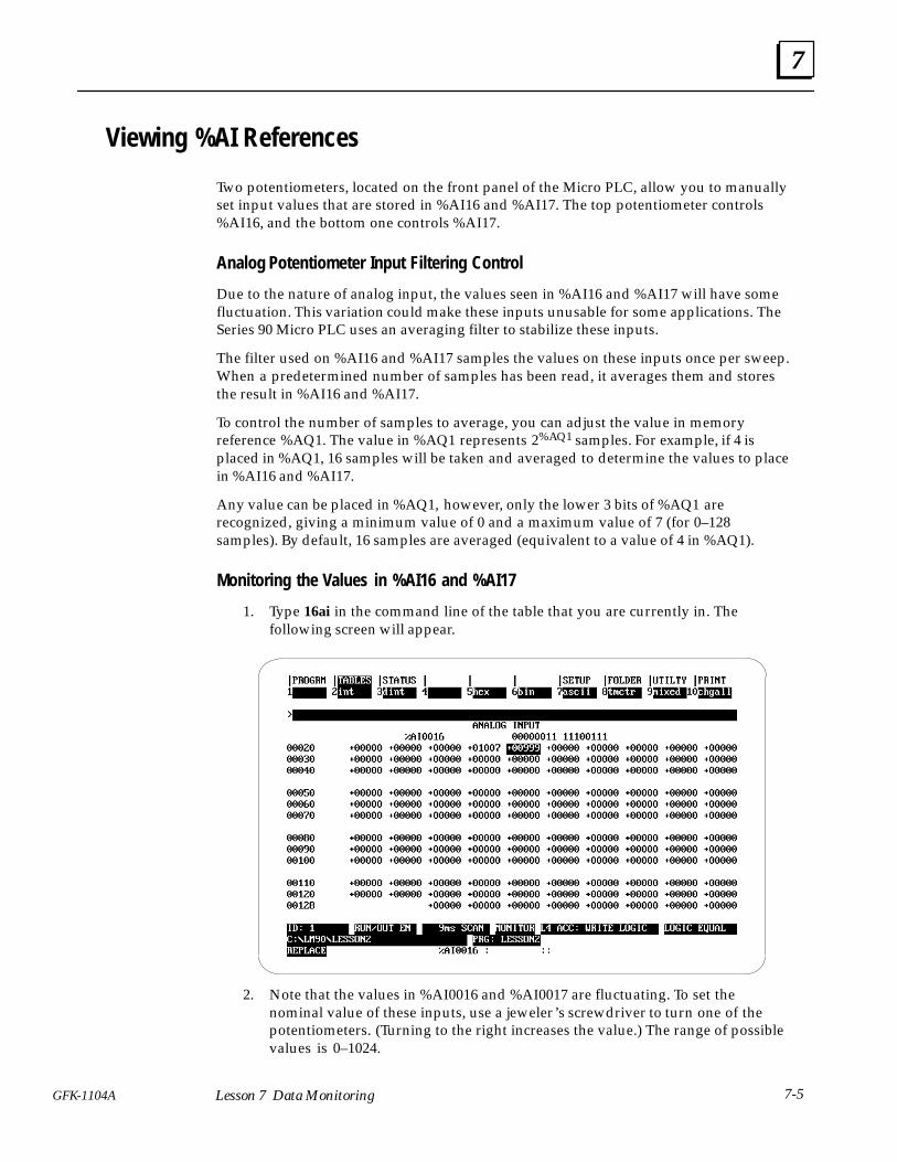
Monitoring the Values in %AI16 and %AI17
1. Type 16ai in the command line of the table that you are currently in. Thefollowing screen will appear.
2. Note that the values in %AI0016 and %AI0017 are fluctuating. To set thenominal value of these inputs, use a jeweler’s screwdriver to turn one of thepotentiometers. (Turning to the right increases the value.) The range of possiblevalues is 0–1024.

7
7-6 Series 90� Micro Programmable Logic Controller Self-Teach Manual – May 1996 GFK-1104A
Writing in the Tables
To change the value in %AQ0001:
1. Type 1aq in the command line. The analog output table will appear, as follows:
2. Press Alt-R to stop the PLC. (Although reference tables can be changed inONLINE mode, this is not a recommended practice.)
3. Enter a new value in the command line, 7 for example, and press Enter.
4. Press Alt-R to return to RUN mode.
5. To observe the results of this change, type 16ai in the command line and pressEnter. The values in %AI0016 and %AI0017 should be fluctuating within asignificantly reduced range,
6. When you have finished experimenting with the data tables, press Esc until youhave returned to the PROGRAMMING SOFTWARE main menu.
GE FANUC
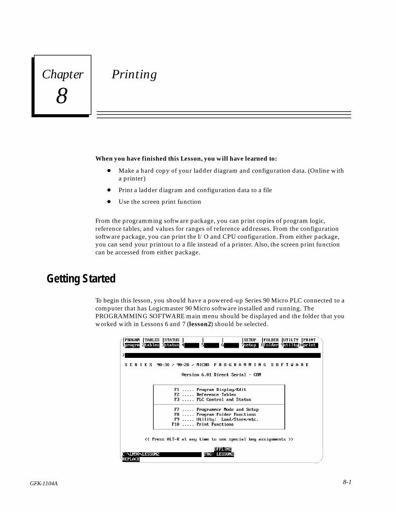
8section level 1 figure bi level 1 table_big level 1
8-1GFK-1104A
Chapter 8 Printing
When you have finished this Lesson, you will have learned to:
� Make a hard copy of your ladder diagram and configuration data. (Online witha printer)
� Print a ladder diagram and configuration data to a file
� Use the screen print function
From the programming software package, you can print copies of program logic,reference tables, and values for ranges of reference addresses. From the configurationsoftware package, you can print the I/O and CPU configuration. From either package,you can send your printout to a file instead of a printer. Also, the screen print functioncan be accessed from either package.
Getting Started
To begin this lesson, you should have a powered-up Series 90 Micro PLC connected to acomputer that has Logicmaster 90 Micro software installed and running. ThePROGRAMMING SOFTWARE main menu should be displayed and the folder that youworked with in Lessons 6 and 7 (lesson2) should be selected.
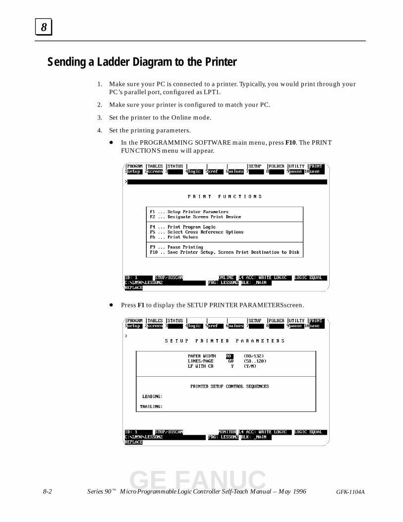
8
8-2 Series 90� Micro Programmable Logic Controller Self-Teach Manual – May 1996 GFK-1104A
Sending a Ladder Diagram to the Printer
1. Make sure your PC is connected to a printer. Typically, you would print through yourPC’s parallel port, configured as LPT1.
2. Make sure your printer is configured to match your PC.
3. Set the printer to the Online mode.
4. Set the printing parameters.
� In the PROGRAMMING SOFTWARE main menu, press F10. The PRINTFUNCTIONS menu will appear.
� Press F1 to display the SETUP PRINTER PARAMETERS screen.
GE FANUC
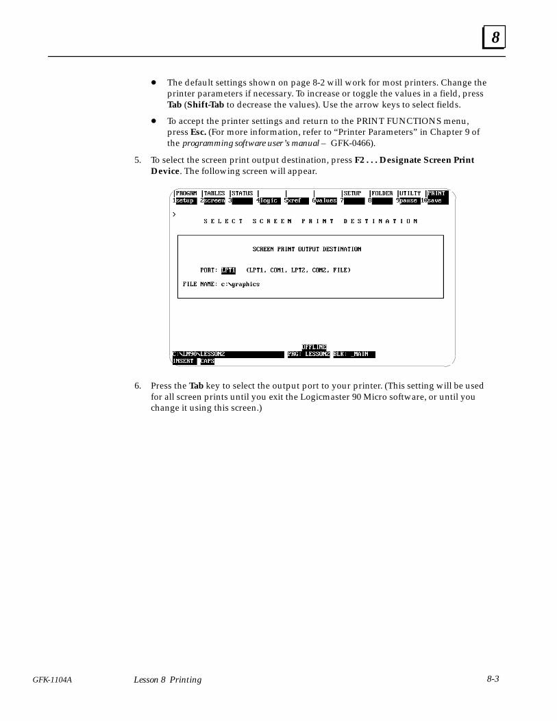
8
8-3GFK-1104A Lesson 8 Printing
� The default settings shown on page 8-2 will work for most printers. Change theprinter parameters if necessary. To increase or toggle the values in a field, pressTab (Shift-Tab to decrease the values). Use the arrow keys to select fields.
� To accept the printer settings and return to the PRINT FUNCTIONS menu,press Esc. (For more information, refer to “Printer Parameters” in Chapter 9 ofthe programming software user’s manual – GFK-0466).
5. To select the screen print output destination, press F2 . . . Designate Screen PrintDevice. The following screen will appear.
6. Press the Tab key to select the output port to your printer. (This setting will be usedfor all screen prints until you exit the Logicmaster 90 Micro software, or until youchange it using this screen.)
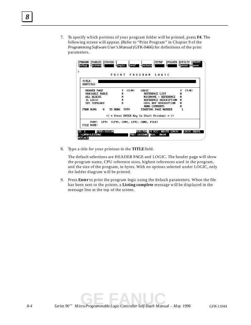
8
8-4 Series 90� Micro Programmable Logic Controller Self-Teach Manual – May 1996 GFK-1104A
7. To specify which portions of your program folder will be printed, press F4. Thefollowing screen will appear. (Refer to “Print Program” in Chapter 9 of theProgramming Software User’s Manual (GFK-0466) for definitions of the printparameters.
8. Type a title for your printout in the TITLE field.
The default selections are HEADER PAGE and LOGIC. The header page will showthe program name, CPU reference sizes, highest references used in the program,and the size of the program, in bytes. With no options selected under LOGIC, onlythe ladder diagram will be printed.
9. Press Enter to print the program logic using the default parameters. When the filehas been sent to the printer, a Listing complete message will be displayed in themessage line at the top of the screen.
GE FANUC
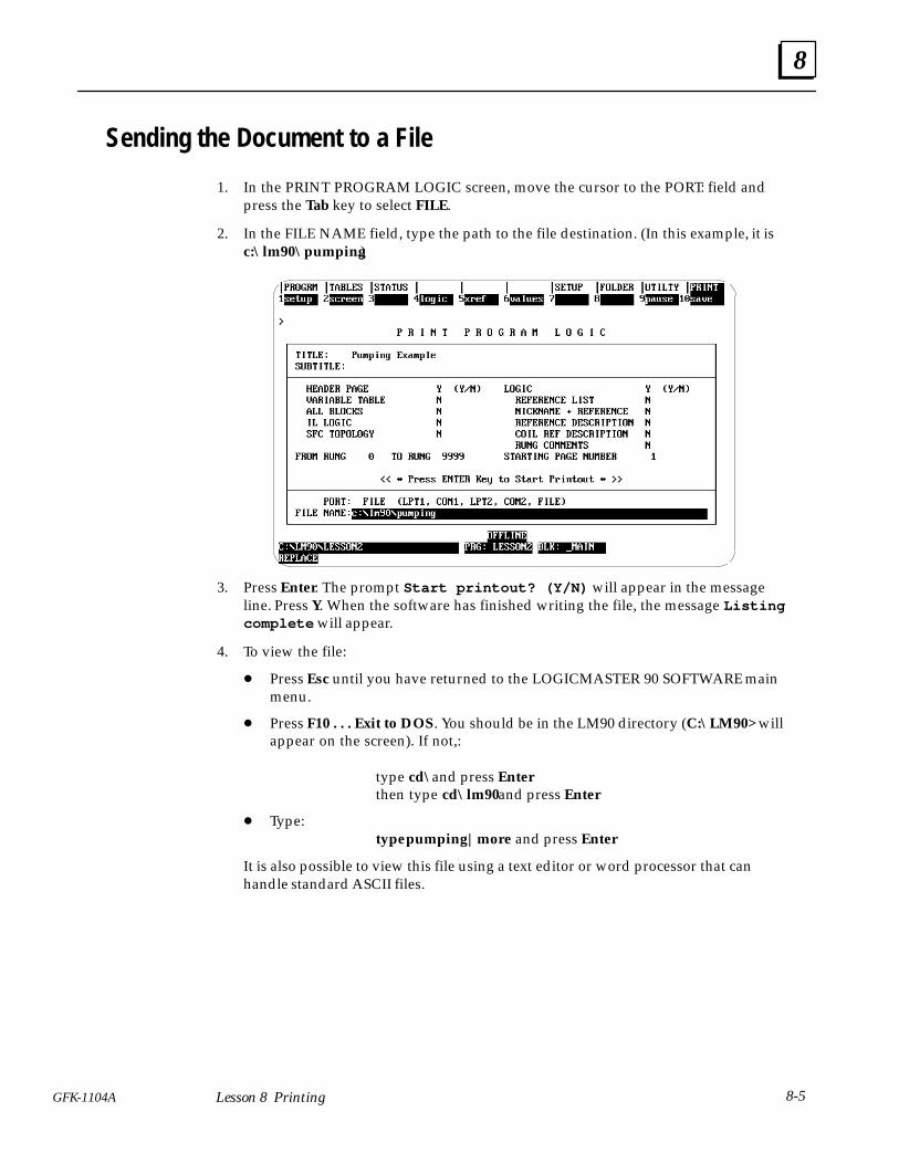
8
8-5GFK-1104A Lesson 8 Printing
Sending the Document to a File
1. In the PRINT PROGRAM LOGIC screen, move the cursor to the PORT: field andpress the Tab key to select FILE.
2. In the FILE NAME field, type the path to the file destination. (In this example, it isc:\lm90\pumping.)
3. Press Enter. The prompt Start printout? (Y/N) will appear in the messageline. Press Y. When the software has finished writing the file, the message Listingcomplete will appear.
4. To view the file:
� Press Esc until you have returned to the LOGICMASTER 90 SOFTWARE mainmenu.
� Press F10 . . . Exit to DOS. You should be in the LM90 directory (C:\LM90> willappear on the screen). If not,:
type cd\ and press Enterthen type cd\lm90 and press Enter
� Type:type pumping|more and press Enter
It is also possible to view this file using a text editor or word processor that canhandle standard ASCII files.
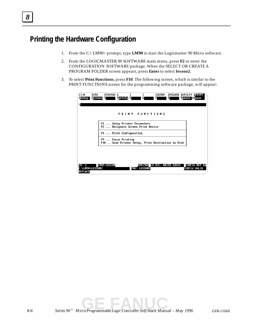
8
8-6 Series 90� Micro Programmable Logic Controller Self-Teach Manual – May 1996 GFK-1104A
Printing the Hardware Configuration
1. From the C:\LM90> prompt, type LM90 to start the Logicmaster 90 Micro software.
2. From the LOGICMASTER 90 SOFTWARE main menu, press F2 to enter theCONFIGURATION SOFTWARE package. When the SELECT OR CREATE APROGRAM FOLDER screen appears, press Enter to select lesson2.
3. To select Print Functions, press F10. The following screen, which is similar to thePRINT FUNCTIONS screen for the programming software package, will appear:
GE FANUC
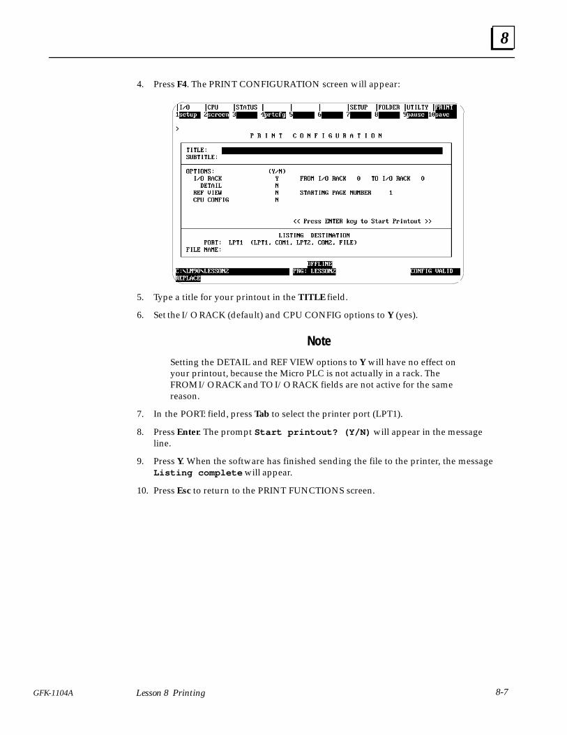
8
8-7GFK-1104A Lesson 8 Printing
4. Press F4. The PRINT CONFIGURATION screen will appear:
5. Type a title for your printout in the TITLE field.
6. Set the I/O RACK (default) and CPU CONFIG options to Y (yes).
Note
Setting the DETAIL and REF VIEW options to Y will have no effect onyour printout, because the Micro PLC is not actually in a rack. TheFROM I/O RACK and TO I/O RACK fields are not active for the samereason.
7. In the PORT: field, press Tab to select the printer port (LPT1).
8. Press Enter. The prompt Start printout? (Y/N) will appear in the messageline.
9. Press Y. When the software has finished sending the file to the printer, the messageListing complete will appear.
10. Press Esc to return to the PRINT FUNCTIONS screen.
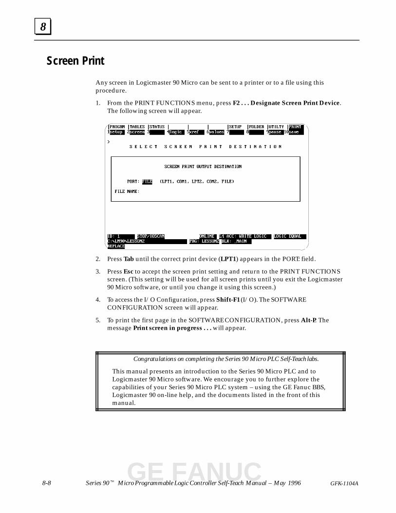
8
8-8 Series 90� Micro Programmable Logic Controller Self-Teach Manual – May 1996 GFK-1104A
Screen Print
Any screen in Logicmaster 90 Micro can be sent to a printer or to a file using thisprocedure.
1. From the PRINT FUNCTIONS menu, press F2 . . . Designate Screen Print Device.The following screen will appear.
2. Press Tab until the correct print device (LPT1) appears in the PORT: field.
3. Press Esc to accept the screen print setting and return to the PRINT FUNCTIONSscreen. (This setting will be used for all screen prints until you exit the Logicmaster90 Micro software, or until you change it using this screen.)
4. To access the I/O Configuration, press Shift-F1 (I/O). The SOFTWARECONFIGURATION screen will appear.
5. To print the first page in the SOFTWARE CONFIGURATION, press Alt-P. Themessage Print screen in progress . . . will appear.
Congratulations on completing the Series 90 Micro PLC Self-Teach labs.
This manual presents an introduction to the Series 90 Micro PLC and toLogicmaster 90 Micro software. We encourage you to further explore thecapabilities of your Series 90 Micro PLC system – using the GE Fanuc BBS,Logicmaster 90 on-line help, and the documents listed in the front of thismanual.
GE FANUC
section level 1 figure_ap level 1 table_ap level 1 A
A-1GFK-1104A
Appendix A High Speed Counter Applications
This appendix describes several typical applications that use High Speed Counters. TheSeries 90 Micro PLC User’s Manual (GFK-1065) provides connection and configurationinformation for the High Speed Counters.
The application examples consist of:
� Counter Cascading A-2. . . . . . . . . . . . . . . . . . . . . . . . . . . . . . . . . . . . . . . . . . . . . . . . . . . . .
� RPM Indicator A-3. . . . . . . . . . . . . . . . . . . . . . . . . . . . . . . . . . . . . . . . . . . . . . . . . . . . . . . .
� Tolerance Checking A-4. . . . . . . . . . . . . . . . . . . . . . . . . . . . . . . . . . . . . . . . . . . . . . . . . . . .
� Measuring Pulse Time A-5. . . . . . . . . . . . . . . . . . . . . . . . . . . . . . . . . . . . . . . . . . . . . . . . . .
� Measuring Total Material Length A-6. . . . . . . . . . . . . . . . . . . . . . . . . . . . . . . . . . . . . . . . .
� Material Handling Conveyor Control A-7. . . . . . . . . . . . . . . . . . . . . . . . . . . . . . . . . . . .
� Timing Pulse Generation A-8. . . . . . . . . . . . . . . . . . . . . . . . . . . . . . . . . . . . . . . . . . . . . . .

A
Series 90� Micro Programmable Logic Controller Self-Teach Manual – May 1996A-2 GFK-1104A
Counter Cascading
Type A counters can be cascaded to accumulate greater count values than are possiblewith a single 2-byte counter. This can be accomplished by using the preset output of onecounter for the count input of the next as shown below.
COUNTER 2COUNTER 1COUNTERPULSES
a43028
For example, if a 4-byte Up Counter is required, use two counters configured for the UPdirection and:
1. Set the Count Limits for both counters at their maximum values:
LOW = –32768 and HIGH = +32767
2. Set the output preset for counter 1 at:
a44217
UP
OFFON
0 150ON = 0
OFF = 150
3. Connect counter 1 output to the counter 2 input.
4. Connect the count pulse stream to the counter 1 input.
Similarly, Down Counters can be cascaded by configuring all counters for the Downdirection, setting the limits at the maximum values and reversing the output presets. Forexample:
a44218
DOWN
ONOFF0 150OFF = 0
ON = 150
Type A Counter Operating Count Directions
Counter Number Crane Direction Count Direction
Counter 1 → UP
Counter 2 → Not counting
Counter 1 ← DOWN
Counter 2 ← UP
GE FANUC
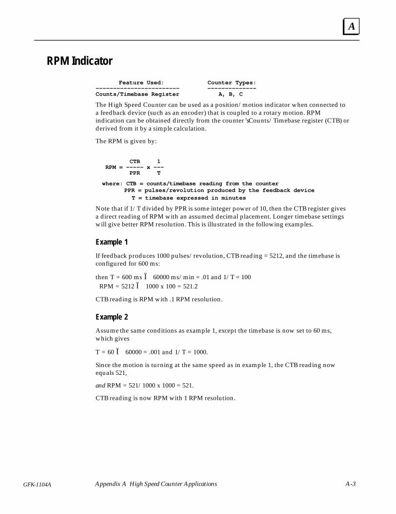
A
A-3GFK-1104A Appendix A High Speed Counter Applications
RPM Indicator
Feature Used: Counter Types:–––––––––––––––––––––––– ––––––––––––––Counts/Timebase Register A, B, C
The High Speed Counter can be used as a position/motion indicator when connected toa feedback device (such as an encoder) that is coupled to a rotary motion. RPMindication can be obtained directly from the counter’s Counts/Timebase register (CTB) orderived from it by a simple calculation.
The RPM is given by:
CTB 1 RPM = ––––– x ––– PPR T
where: CTB = c ounts/timebase reading from the counter PPR = pulses/revolution produced by the feedback device T = timebase expressed in minutes
Note that if 1/T divided by PPR is some integer power of 10, then the CTB register givesa direct reading of RPM with an assumed decimal placement. Longer timebase settingswill give better RPM resolution. This is illustrated in the following examples.
Example 1
If feedback produces 1000 pulses/revolution, CTB reading = 5212, and the timebase isconfigured for 600 ms:
then T = 600 ms Ï 60000 ms/min = .01 and 1/T = 100 RPM = 5212 Ï 1000 x 100 = 521.2
CTB reading is RPM with .1 RPM resolution.
Example 2
Assume the same conditions as example 1, except the timebase is now set to 60 ms,which gives
T = 60 Ï 60000 = .001 and 1/T = 1000.
Since the motion is turning at the same speed as in example 1, the CTB reading nowequals 521,
and RPM = 521/1000 x 1000 = 521.
CTB reading is now RPM with 1 RPM resolution.
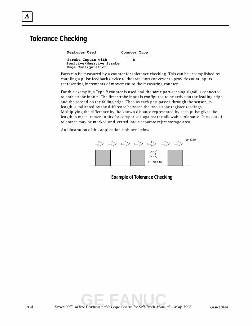
A
Series 90� Micro Programmable Logic Controller Self-Teach Manual – May 1996A-4 GFK-1104A
Tolerance Checking
Features Used: Counter Type: –––––––––––––––– ––––––––––––– Strobe Inputs with B Positive/Negative Strobe Edge Configuration
Parts can be measured by a counter for tolerance checking. This can be accomplished bycoupling a pulse feedback device to the transport conveyor to provide count inputsrepresenting increments of movement to the measuring counter.
For this example, a Type B counter is used and the same part-sensing signal is connectedto both strobe inputs. The first strobe input is configured to be active on the leading edgeand the second on the falling edge. Then as each part passes through the sensor, itslength is indicated by the difference between the two strobe register readings.Multiplying the difference by the known distance represented by each pulse gives thelength in measurement units for comparison against the allowable tolerance. Parts out oftolerance may be marked or diverted into a separate reject storage area.
An illustration of this application is shown below.
a44220
SENSOR
Example of Tolerance Checking
GE FANUC
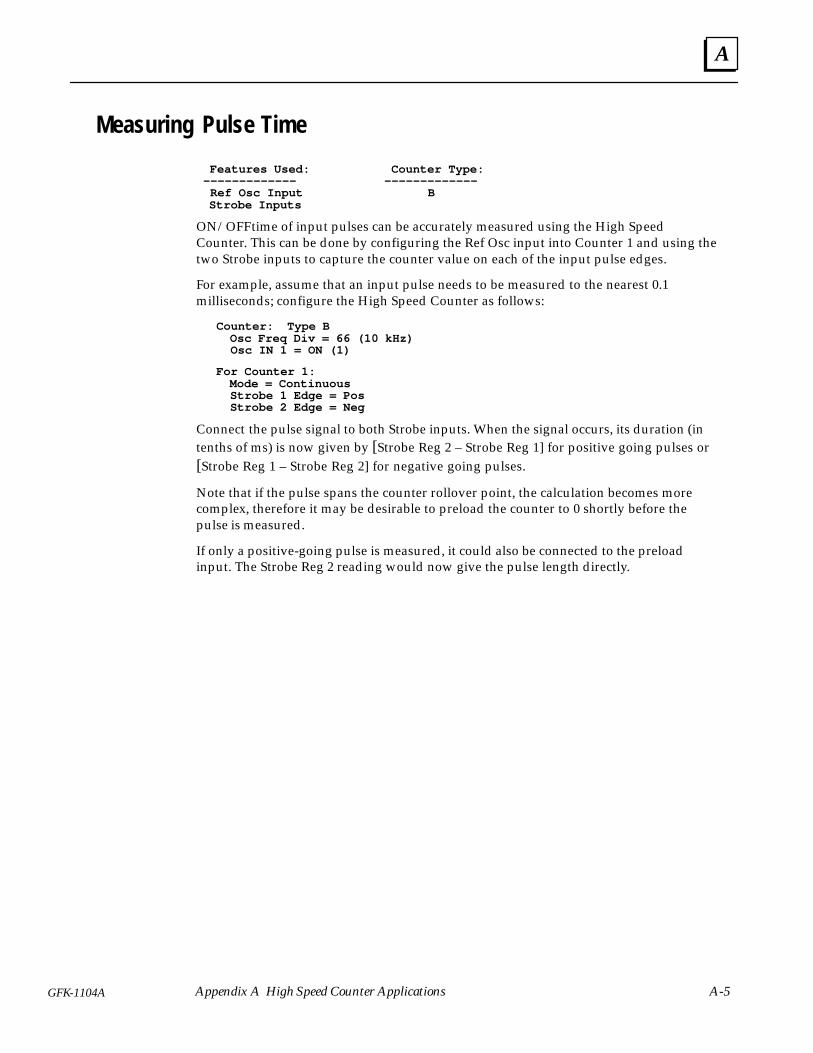
A
A-5GFK-1104A Appendix A High Speed Counter Applications
Measuring Pulse Time
Features Used: Counter Type: ––––––––––––– ––––––––––––– Ref Osc Input B Strobe Inputs
ON/OFF time of input pulses can be accurately measured using the High SpeedCounter. This can be done by configuring the Ref Osc input into Counter 1 and using thetwo Strobe inputs to capture the counter value on each of the input pulse edges.
For example, assume that an input pulse needs to be measured to the nearest 0.1milliseconds; configure the High Speed Counter as follows:
Counter: Type B Osc Freq Div = 66 (10 kHz) Osc IN 1 = ON (1)
For Counter 1: Mode = Continuous Strobe 1 Edge = Pos Strobe 2 Edge = Neg
Connect the pulse signal to both Strobe inputs. When the signal occurs, its duration (intenths of ms) is now given by [Strobe Reg 2 – Strobe Reg 1] for positive going pulses or[Strobe Reg 1 – Strobe Reg 2] for negative going pulses.
Note that if the pulse spans the counter rollover point, the calculation becomes morecomplex, therefore it may be desirable to preload the counter to 0 shortly before thepulse is measured.
If only a positive-going pulse is measured, it could also be connected to the preloadinput. The Strobe Reg 2 reading would now give the pulse length directly.
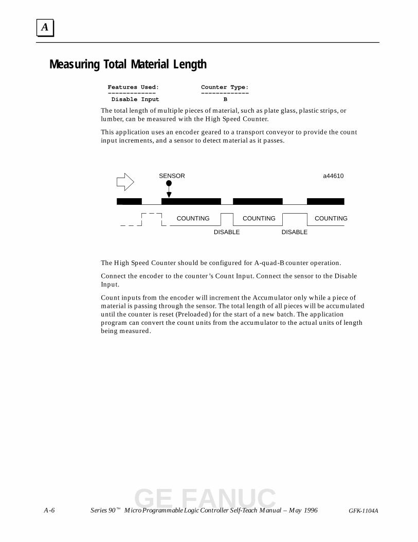
A
Series 90� Micro Programmable Logic Controller Self-Teach Manual – May 1996A-6 GFK-1104A
Measuring Total Material Length
Features Used: Counter Type: ––––––––––––– ––––––––––––– Disable Input B
The total length of multiple pieces of material, such as plate glass, plastic strips, orlumber, can be measured with the High Speed Counter.
This application uses an encoder geared to a transport conveyor to provide the countinput increments, and a sensor to detect material as it passes.
a44610
COUNTING COUNTING COUNTING
SENSOR
DISABLE DISABLE
The High Speed Counter should be configured for A-quad-B counter operation.
Connect the encoder to the counter’s Count Input. Connect the sensor to the DisableInput.
Count inputs from the encoder will increment the Accumulator only while a piece ofmaterial is passing through the sensor. The total length of all pieces will be accumulateduntil the counter is reset (Preloaded) for the start of a new batch. The applicationprogram can convert the count units from the accumulator to the actual units of lengthbeing measured.
GE FANUC
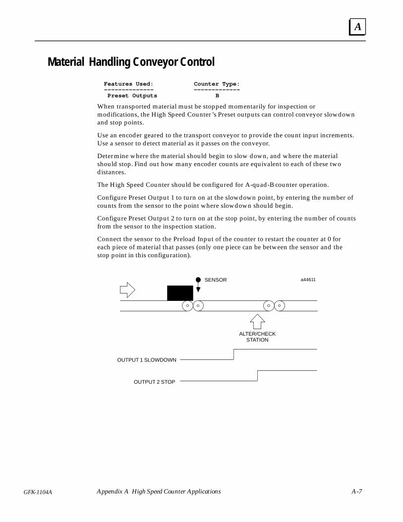
A
A-7GFK-1104A Appendix A High Speed Counter Applications
Material Handling Conveyor Control
Features Used: Counter Type: –––––––––––––– ––––––––––––– Preset Outputs B
When transported material must be stopped momentarily for inspection ormodifications, the High Speed Counter’s Preset outputs can control conveyor slowdownand stop points.
Use an encoder geared to the transport conveyor to provide the count input increments.Use a sensor to detect material as it passes on the conveyor.
Determine where the material should begin to slow down, and where the materialshould stop. Find out how many encoder counts are equivalent to each of these twodistances.
The High Speed Counter should be configured for A-quad-B counter operation.
Configure Preset Output 1 to turn on at the slowdown point, by entering the number ofcounts from the sensor to the point where slowdown should begin.
Configure Preset Output 2 to turn on at the stop point, by entering the number of countsfrom the sensor to the inspection station.
Connect the sensor to the Preload Input of the counter to restart the counter at 0 foreach piece of material that passes (only one piece can be between the sensor and thestop point in this configuration).
a44611
OUTPUT 1 SLOWDOWN
ALTER/CHECKSTATION
SENSOR
OUTPUT 2 STOP
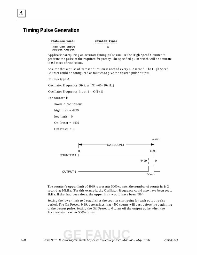
A
Series 90� Micro Programmable Logic Controller Self-Teach Manual – May 1996A-8 GFK-1104A
Timing Pulse Generation
Features Used: Counter Type: ––––––––––––– ––––––––––––– Ref Osc Input A Preset Output
Applications requiring an accurate timing pulse can use the High Speed Counter togenerate the pulse at the required frequency. The specified pulse width will be accurateto 0.5 msec of resolution.
Assume that a pulse of 50 msec duration is needed every 1/2 second. The High SpeedCounter could be configured as follows to give the desired pulse output.
Counter type A
Oscillator Frequency Divider (N) =66 (10kHz)
Oscillator Frequency Input 1 = ON (1)
For counter 1:
mode = continuous
high limit = 4999
low limit = 0
On Preset = 4499
Off Preset = 0
a44612
COUNTER 1
OUTPUT 1
1/2 SECOND
50mS
49990
4499 0
The counter’s upper limit of 4999 represents 5000 counts, the number of counts in 1/2second at 10kHz. (For this example, the Oscillator Frequency could also have been set to1kHz. If that had been done, the upper limit would have been 499.)
Setting the lower limit to 0 establishes the counter start point for each output pulseperiod. The On Preset, 4499, determines that 4500 counts will pass before the beginningof the output pulse. Setting the Off Preset to 0 turns off the output pulse when theAccumulator reaches 5000 counts.
GE FANUC
Index
Index-1GFK-1104 Series 90� Micro Programmable Logic Controller Self-Teach Manual – August 1995
AAnalog inputs, 7-5
Application examplescounter cascading, A-2 material handling conveyor control,
A-7 measuring pulse time, A-5 measuring total material length, A-6 rpm indicator, A-3 timing pulse generation, A-8 tolerance checking, A-4
Averaging filter, 7-5
BBulletin Board, iii
CCatalog numbers
PLCIC693UAA003, 1-4 , 3-1 IC693UDR001, 1-4 , 3-1 IC693UDR002, 1-4 , 3-1
Software, Cable Kit & manuals,IC640HWP300, 3-1
Clearing memory, 6-2
Configuration, printing, 8-6
ConnectionsI/O, 3-3 power supply, 3-3
Copying program folders to diskettes, 5-7
Counter, cascading, A-2
CPU, 1-5
Creating a new folder, 6-3
Creating a program, 5-3
DData tables
analog input, 7-5 analog output, 7-6 input status, 7-2 internal status, 7-3 mixed, 7-4
register, 7-3 viewing, 7-2–7-3 writing in, 7-6
Definition, PLC, 1-1
Diagnostics, power-up, 3-5
EEditing tips, for ladder diagram, 6-7
Editor options, 6-6
Elementsprogram, searching for, 6-9 screen, 4-4
FField wiring, 3-3
Foldercopying, 5-7 new, 4-3 , 6-3
Folder functions, program, 5-7
HHigh speed counters
application examples, A-1 outputs, 1-4
II/O circuits, 1-3
I/O connections, wiring to, 3-3
Indicators, power-up sequence, 3-5
Input circuitsAC, 1-4 analog, 1-4 DC, 1-4
Input switches, 3-2
Installing the programming software, 3-6
KKey shortcuts, 4-7
LLadder diagrams, 1-5 , 2-2
Index
Index-2 GFK-1104Series 90� Micro PLC Self-Teach Manual–August 1995
Language, changing, 4-2
LEDs, OK/RUN/PWR indicators, 3-5
Loading a file, 5-9
MMaterial handling conveyor control, A-7
Measuring pulse time, example of, A-5
Measuring total material length, A-6
Message line, 4-4
Mixed table, 7-4
NNicknames, 6-5 , 6-10
OONLINE mode, 5-2
Output circuitsAC, 1-4 relay, 1-4
PPLC
catalog numbers, 3-1 definition, 1-1 loading program from, 5-9 power-up sequence, 3-5 storing program to, 5-5 sweep sequence, 1-2
PLC application, 2-1
Potentiometers, 1-4 , 7-5
Power supply, wiring to, 3-3
Power-up sequence, 3-5
Printing to a file, 8-5
Program folder functions, 5-7 , 6-3
Program folders, creating, 6-3
Programming devices, 3-5
RReferences
automatically entering in Variable Dec-larations Table, 6-6 , 6-10
tables, 7-1–7-7
RPM indicator, example of, A-3
Running a program, 5-6
Running and stopping the PLC, 4-5
SScreen elements, 4-4
Screen print, 8-8
Search utility, 6-9
Self-diagnostics, 3-5
Softwareinstalling, 3-6 Logicmaster 90
key shortcuts, 4-7 screen elements, 4-4 starting, 4-1
State, RUN/STOP, 4-4 , 4-5
Status block, on Logicmaster 90 screen,4-4
Store program to PLC, 5-5
Sweep sequence, 1-2
TTables
mixed, 7-4 viewing, 7-2 writing in, 7-6
Timing pulse generation, A-8
Tolerance checking, example of, A-4
VVariable Declarations Table, 6-5 , 6-10
WWiring, field connections, 3-3
GE FANUC