Series 751P Probe Type LowWater Cut-Off
8
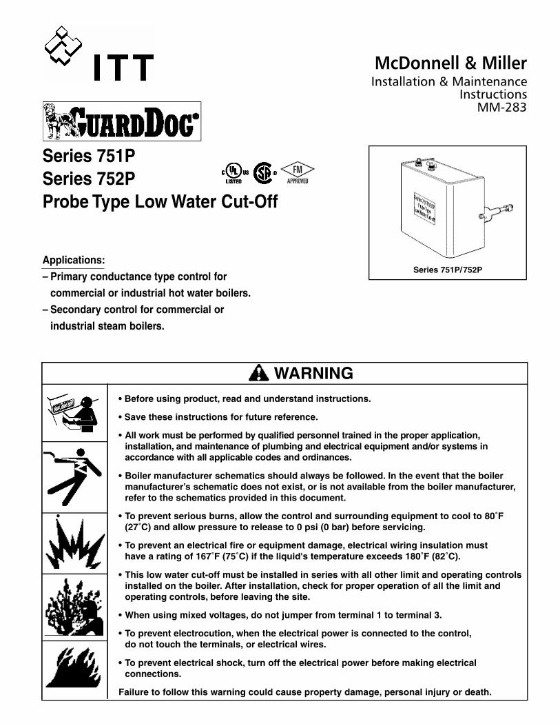
Series 751P/ 752P • Before using product, read and understand instructions. • Save these instructions for future reference. • All work must be performed by qualified personnel trained in the proper application, installation, and maintenance of plumbing and electrical equipment and/or systems in accordance with all applicable codes and ordinances. • Boiler manufacturer schematics should always be followed. In the event that the boiler manufacturer’s schematic does not exist, or is not available from the boiler manufacturer, refer to the schematics provided in this document. • • To prevent serious burns, allow the control and surrounding equipment to cool to 80˚F (27˚C) and allow pressure to release to 0 psi (0 bar) before servicing. • To prevent an electrical fire or equipment damage, electrical wiring insulation must have a rating of 167˚F (75˚C) if the liquid's temperature exceeds 180˚F (82˚C). • This low water cut-off must be installed in series with all other limit and operating controls installed on the boiler. After installation, check for proper operation of all the limit and operating controls, before leaving the site. • When using mixed voltages, do not jumper from terminal 1 to terminal 3. • To prevent electrocution, when the electrical power is connected to the control, do not touch the terminals, or electrical wires. • To prevent electrical shock, turn off the electrical power before making electrical connections. Failure to follow this warning could cause property damage, personal injury or death. WARNING Series 751P Series 752P Probe Type Low Water Cut-Off Applications: – Primary conductance type control for commercial or industrial hot water boilers. – Secondary control for commercial or industrial steam boilers. McDonnell & Miller Installation & Maintenance Instructions MM-283
Transcript of Series 751P Probe Type LowWater Cut-Off
Series 751P/752P
• Before using product, read and understand instructions.
• Save these instructions for future reference.
• All work must be performed by qualified personnel trained in the proper application,
i n s t a l l a t i o n , and maintenance of plumbing and electrical equipment and/or systems in
a c c o rdance with all applicable codes and ord i n a n c e s .
• Boiler manufacturer schematics should always be followed. In the event that the boiler
manufacturer’s schematic does not exist, or is not available from the boiler manufacturer,
refer to the schematics provided in this document.
• • To prevent serious burns, allow the control and surrounding equipment to cool to 80˚F
(27˚C) and allow pressure to release to 0 psi (0 bar) before servicing.
• To prevent an electrical fire or equipment damage, electrical wiring insulation must
have a rating of 167˚F (75˚C) if the liquid's temperature exceeds 180˚F (82˚C).
• This low water cut-off must be installed in series with all other limit and operating controls
installed on the boiler. After installation, check for proper operation of all the limit and
operating controls, before leaving the site.
• When using mixed voltages, do not jumper from terminal 1 to terminal 3.
• To prevent electrocution, when the electrical power is connected to the control,
do not touch the terminals, or electrical wires.
• To prevent electrical shock, turn off the electrical power before making electrical
connections.
Failure to follow this warning could cause property damage, personal injury or death.
WARNING
Series 751P
Series 752P
Probe Type Low Water Cut-Off
Applications:
– Primary conductance type control for
commercial or industrial hot water boilers.
– Secondary control for commercial or
industrial steam boilers.
McDonnell & MillerInstallation & Maintenance
Instructions MM-283
2
SPECIFICATIONS
Hz: 50/60
Control Power Consumption: 3 VA (max.)
Probe Sensitivity: 20,000 ohm
(water/glycol mixtures up to 50% concentration may be used)
Automatic Reset Models
Whenever water is below the level of the probe, the
control will go into a low water condition. When the
water level has been restored, the control will auto-
matically return to a run condition.
Manual Reset Models
If a low water condition occurs (water off probe), the
manual reset button must be pressed once the
water level is restored to a level above the probe.
CSD-1 Code Compliance
On Manual Reset units, if the control is in a low
water condition (water off probe) when there is an
interruption of power, the control will remain in a low
water condition when power is restored. The reset
button will need to be pressed when the water level
is restored to a level above the probe.
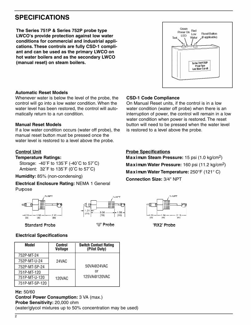
The Series 751P & Series 752P probe type
LWCO's provide protection against low water
conditions for commercial and industrial appli-
cations. These controls are fully CSD-1 compli-
ant and can be used as the primary LWCO on
hot water boilers and as the secondary LWCO
(manual reset) on steam boilers.
C o n t rol Unit
Temperature Ratings:
S t o ra g e : -40˚F to 135˚F (-40˚C to 57˚C)
A m b i e n t : 32˚F to 135˚F (0˚C to 57˚C)
H u m i d i t y : 85% (non-condensing)
Electrical Enclosure Rating: NEMA 1 Genera l
P u rp o s e
M o d e l C o n t r o l Switch Contact RatingVoltage (Pilot Duty)
752P-MT-24
752P-MT-U-24 24VAC
752P-MT-SP-24 50VA@24VAC
751P-MT-120
120VAC
or
751P-MT-U-120 125VA@120VAC
751P-MT-SP-120
Electrical Specifications
P robe Specifications
M a x i mum Steam Pressure: 15 psi (1.0 kg/cm2)
M a x i mum Water Pressure: 160 psi (11.2 kg/cm2)
M a x i mum Water Te m p e r a t u r e : 250°F (121° C)
Connection Size : 3/4" NPT
3
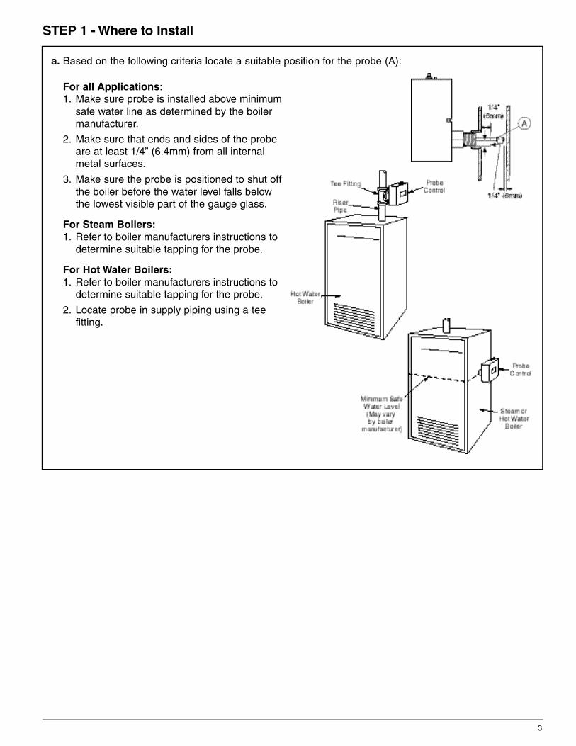
a. Based on the following criteria locate a suitable position for the probe (A):
For all Applications:
1. Make sure probe is installed above minimum
safe water line as determined by the boiler
manufacturer.
2. Make sure that ends and sides of the probe
are at least 1/4” (6.4mm) from all internal
metal surfaces.
3. Make sure the probe is positioned to shut off
the boiler before the water level falls below
the lowest visible part of the gauge glass.
For Steam Boilers:
1. Refer to boiler manufacturers instructions to
determine suitable tapping for the probe.
For Hot Water Boilers:
1. Refer to boiler manufacturers instructions to
determine suitable tapping for the probe.
2. Locate probe in supply piping using a tee
fitting.
STEP 1 - Where to Install

4
d. Using the flatblade screwdriver, loosen
the two (2) screws that secure the
cover (G) to the control about 1-1/2
turns and remove cover.
b. Apply a small amount of pipe dope to the first
external threads (D) of the probe (A).
c. Using a wrench, tighten the probe (A) into the
tapped connection (E) that was determined in
Step 1 of these instructions. Tighten to 47 ft•lb
(64 N•m).
NOTE: Be sure to align the probe so that the
mounting screws (F) are in a hori zontal position.
I M P O RTA N T: Do not use Teflon® tape or threadsealant.

5
e. Electrical Conduit Connection
• Connect electric conduit using knockouts
provided.
• Follow accepted electrical practices when
installing fittings and making connections.
• Refer to and follow codes and standards
when selecting the types of electrical
fittings and conduit.
b . Using a flatblade screw d ri ve r, loosen the probe
mounting screws (F) 1/8" (3mm) about 1-1/2 turn s
and slip the control housing (G) over these two
s c r ews at a 20˚ angle.
a . Push out the probe knockouts and remove
completely from the control housing.
c . Rotate the control housing (G) 20˚ counterclock w i s e
so that the slots in the control base are firmly under
the screw heads. Tighten the mounting screws (F)
to approximately 2 ft•lb (2.6 N•m).
d . R e m ove wingnut from probe and position ring
t e rminal of probe wire on threaded probe rod.
Secure with wingnu t .

C o n t rol W i r i n g : Same vo l t age for control and burner circ u i t
• Connect hot wire to terminal 1
• Connect neutral wire to terminal 2
• Connect jumper wire from Te rminal 1 to Te rminal 3
• Connect wire from beginning of Burner circuit
( t h e rmostat, gas va l ve, limits, etc.) to terminal 5
• Connect wire from end of Burner circuit to terminal 2
To prevent electrical fire or equipment damage,electrical wiring must have a rating of 167°F(75C) if the liquid's temperature exceeds 180°F (82°C).Failure to follow this warning could causeproperty damage, personal injury or death.
WARNING
STEP 5 - Electrical Wiring
Boiler manufacturer schematics should alw ays be fo l l ow e d.In the event that the boiler manufacturer's schematic doesnot exist, or is not available from the boiler manufacturer,refer to the schematics provided in this document.
IMPORTANT
Probe wires should be minimum 18 AWG strandedwith glass braided Silicone jacket (UL 3071) suitablefor high temperature (200°C) service.
NOTE
Wiring Diagram Legends1 . Bold lines indicate action to be taken in Step show n .
2 . Dotted bl a ck lines indicate internal wiri n g .
C o n t rol W i r i n g : D i f ferent vo l t age for control and burner circ u i t
• Connect hot wire to terminal 1
• Connect neutral wire to terminal 2
• Locate Boiler Burner Safety Circuit
and connect wires to Te rminals 3 & 5
as shown to interrupt circuit
6

STEP 6 - Testing and Diagnostic Procedures
7
Series 750 LWCO with Green Power On LED and Red Low Water LED
Start-Up
a . B e fore filling the system, t u rn on the electric power to the boiler.
1 . Upon initial power up, the Green and Red lights will flash
s i multaneously 4 times.
2 . The Green and Red lights will turn “ O N ” .
3 . The bu rner will never turn “ O N ” d u ring power up, If water is off
the probe.
b . N ow fill the boiler with water.
(auto reset units only )
1 . When water touches the probe, the Green light will remain “ O N ” .
2 . The Red light will turn “ O F F ” and the bu rner will turn “ O N ” as long
as there is water on the probe.
( m a nual reset units only )
(When water returns to the probe, nothing will happen until the manual reset button is depressed.)
1 . After depressing manual reset button, the Green and Red lights will flash simultaneously 4 times.
2 . Then the Green light will turn “ O N ” and the Red light will turn “ O F F ” .
3 . The bu rner will turn “ O N ” as long as there is water in the probe.
Manually Testing Control
c . S l ow ly drain the boiler of water.
(both auto and manual reset units)
1 . When the water drops off the probe, the Green light will remain “ O N ” .
2 . The Red light will turn “ O N ” and the bu rner will turn “OFF”, if water is off the probe.
Testing Control Using “Test Button”
d . Depressing the test button with “water on pro b e ” (auto reset units only ) :
(Must depress and hold test button to activate test cycle. )
1 . When test cycle is activated the Red and Green lights will flash simultaneously 3 times.
2 . The Red light will turn “ O N ”
3 . The bu rner will turn “ O F F ” .
4 . The Green light will continue flashing as long as the test button is depressed.
(Release test button, if water is still on probe. )
5 . The Green lights will stop flashing and turn “ O N ” .
6 . Then Red light will turn “ O F F ” .
7 . The bu rner will turn “ O N ” as long as there is water in the probe.
e. Depressing the test button with “water on pro b e ” ( m a nual resets units only ) :
(Must depress and hold test button to activate test cycle. )
1 . When test cycle is activated the Red and Green lights will flash simultaneously 3 times.
2 . The Red light will turn “ O N ”
3 . The bu rner will turn “ O F F ” .
4 . The Green light will continue flashing as long as the test button is depressed.
(Release test bu t t o n .You must depress the manual reset button to unlock the low water cut-off. )
5 . After depressing manual reset button, the Green and Red lights will flash simultaneously 4 times.
6 . Then the Green light will turn “ O N ” and the Red light will turn “ O F F ” .
7 . The bu rner will turn “ O N ” as long as there is water in the probe.
f. Depressing the test button with “water off pro b e ” (both auto and manual reset units):
(Since control is in “ l ow wa t e r ” the Green light will flash and the Red light will remain “ O N ” .The bu rn e r
will remain “ O F F ” .
CSD-1 Compliance
On manual Reset units, if the control is in a low water condition (water off probe) when there is an inter-
ruption of powe r, the control will remain in a low water condition when power is restored.The reset bu t t o n
will need to be pressed when the water level is restored to a level above the probe.
If control fails to operate, perform the following diagnostic checks.
1. Check to be sure the water level in the boiler is at or above the level of the probe.
2. Re-check all wiring to ensure proper connections as specified in boiler manufacturers wiring
diagrams or these instructions.
3. Check to ensure that Teflon® tape has not been used on the threaded connection of the electrode
to the boiler.
4. Re-check the electrical ground connection for the remote sensor and control unit.
5. Check the quality of the boiler water to ensure adequate conductance.
MAINTENANCE
SCHEDULE:• Inspect probe annually or more frequently for scale build-up and clean or replace if necessary.
Make certain there is no scale or build-up on the probe or it's white Teflon® insulator. Be careful not to
damage the Teflon® insulator.
• Test the low water cut-off annually or more frequently, if required by code.
Replace Probe if:• Teflon® insulator is cracked or wo r n .• P robe is loose.Failure to fo l l ow this caution could cause pro p e rty damage, p e rsonal injury or death.
CAUTION
Clean probe by wiping with non-abrasive cloth and rinsing with clean water. DO NOTuse sharp instruments to remove any accumulations of rust or scale.
NOTE
• Replace probe every 10 years. More frequent replacement of the probe is required if it is used in locales
where significant water treatment is required, or in applications with high make-up water requirements
• Replace the low water cut-off every 15 years.
ITT8200 N. Austin Ave.Morton Grove, IL 60053tel: 847-966-3700fax: 847-966-9052www.mcdonnellmiller.com
McDonnell & Miller
©2010 ITT Corporation Printed in U.S.A. 3-10 210995