Series 190 – Large vacuum gate valve – DN 900–1250 mm Operating & Maintenance Instructions...
25
Installation, Operating & Maintenance Instructions 600242EA Edition 2013-08-12 Large vacuum gate valve with double acting pneumatic actuator Series 190 DN 900 – 1250 mm (I. D. 36" – 50") This manual is valid for the following product ordering numbers: 19059- . E14 / 24 / 34 / 44 19060- . E14 / 24 / 34 / 44 19062- . E14 / 24 / 34 / 44 Sample picture
Transcript of Series 190 – Large vacuum gate valve – DN 900–1250 mm Operating & Maintenance Instructions...

Installation, Operating & Maintenance Instructions
600242EA Edition 2013-08-12
Large vacuum gate valve with double acting pneumatic actuator
Series 190 DN 900 – 1250 mm (I. D. 36" – 50") This manual is valid for the following product ordering numbers:
19059- . E14 / 24 / 34 / 44 19060- . E14 / 24 / 34 / 44 19062- . E14 / 24 / 34 / 44
Sample picture
+0.10+0.30
-0.30-0.10
ISO 13715
Sauberkeitsstufe 1 = mediumberührend
Front Page Design
1
3
1 Sealing surface2 Body lower part3 Body upper part4 Actuator
2
4Unpacking
Unpacking (2)
1
2
3
1 Flange A2 Flange B3 Screws
1
2
3
4
5
6
7
Maintenace
1 Lifting ropes2 Load Ring3 Screws / Pins4 Body upper part5 Bonnet seal6 Bearings7 Body lower part
900-1250
1:20
575397 Blatt /
Werkstoff Bez.Datum
VAT-Artikelnummer
VAT Vakuumventile AG
Index
höchste Nr.
Gezeichnet
Massstab
Oberfl. [mm2]
Zünd R.
Gewicht [kg]
-
1
Zeichnung für MBA
---
3D Modellnummer
25.01.13
All
e V
AT
-No
rmd
ok
um
ente
, au
f d
ie i
n d
iese
r Z
eich
nu
ng
verw
iese
n w
ird
, st
eh
en
au
f d
er
Inte
rnets
eit
e
ww
w.v
at.i
nfo
zu
r V
erfÃ
¼g
un
g. S
ie d
ü
rfen
nu
r im
Zu
sam
men
han
g m
it d
iese
r Z
eich
nu
ng
ver
wen
det
wer
den
.
1634.861
575394
Kun
denn
umm
er
Werkstoff Nr.Gewindedarstellung
A2 232732
Die
se Z
eic
hnung b
leib
t unse
r geis
tiges
Eig
entu
m.
Sie
darf
ohne u
nse
re s
chri
ftli
che E
inw
illi
gung
weder
kopie
rt,
verv
ielf
ält
igt
noch d
ritt
en P
er-
son
en m
itg
etei
lt o
der
zu
gÃ
¤n
gli
ch g
emac
ht
wer
den
.
nach VAT Norm N-1016
Index-Zch.Nr.
190
CH-9469 Haag , Switzerland
Tel +41 81 7716161 Fax +41 81 7714830
Index
P rojekt i on E-
Ursprung
= Q-MerkmalsbezeichnungStatus
R DN
Zeichnungsnummer
59639951.24
19062-PE44-0003 A
In Arbeit
IN ARBEIT1
1 2 3 4 5 6 7 8 9 10 11
A
B
C
D
E
F
G
H
Tole
rier
ungs
grun
dsat
z IS
O 80
15:
Unab
hän
gigk
eits
prin
zip
---
kein
e

Series 190
2/25 Edition 2013-08-12 600242EA
Imprint Manufacturer VAT Vakuumventile AG, CH-9469 Haag, Switzerland Website:
Phone:
Fax:
Email:
www.vatvalve.com
+41 81 771 61 61
+41 81 771 48 30
Publisher VAT Vakuumventile AG, CH-9469 Haag, Switzerland Editor VAT Vakuumventile AG, CH-9469 Haag, Switzerland Print VAT Vakuumventile AG, CH-9469 Haag, Switzerland Copyright © VAT Vakuumventile AG 2013 No part of these instructions may be reproduced in any way (photo-
copies, microfilms or any other reproduction processes) nor may it be manipulated with electronic systems, duplicated or distributed without written permission from VAT. Offenders are liable to pay damages.
The original VAT firmware and updated state of the art versions of the
VAT firmware are intended for use with VAT products. The VAT firmware contains a limited, time unlimited user license. The VAT firmware may not be used for purposes other than those intended nor is it permitted to make copies of the VAT firmware. In particular, it is strictly forbidden to give copies of the VAT firmware to other people.
The use of trade names, brand names, trademarks, etc. in these
Instructions does not entitle third parties to consider these names to be unprotected and to use them freely. This is in accordance with the meaning of the laws and acts covering brand names and trademarks.

Series 190
600242EA Edition 2013-08-12 3/25
Contents
1 Description of product ........................................................................ 4 1.1 Identification of product ....................................................................................... 4 1.2 Use of product ..................................................................................................... 4 1.3 Related documents ............................................................................................. 4 1.4 Important information .......................................................................................... 4 1.5 Technical data ..................................................................................................... 4
2 Safety ................................................................................................... 5 2.1 Compulsory reading material .............................................................................. 5 2.2 Danger levels ...................................................................................................... 5 2.3 Personnel qualifications ...................................................................................... 6 2.4 Safety labels ........................................................................................................ 6
3 Design and Function ........................................................................... 7 3.1 Design ................................................................................................................. 7 3.2 Function .............................................................................................................. 7
4 Installation ........................................................................................... 8 4.1 Unpacking ........................................................................................................... 8 4.2 Installation into the system .................................................................................. 9
4.2.1 Admissible forces and bending moments ............................................. 10 4.3 Compressed air connection .............................................................................. 11 4.4 Electrical connection ......................................................................................... 11
5 Operation ........................................................................................... 12 5.1 Normal operation ............................................................................................... 12 5.2 Operation under increased temperature ........................................................... 12 5.3 Behavior in case of compressed air pressure drop .......................................... 12 5.4 Behavior in case of power failure ...................................................................... 12
5.4.1 Manual emergency operation ............................................................... 12 5.5 Trouble shooting ............................................................................................... 14
6 Maintenance ...................................................................................... 15 6.1 Maintenance intervals ....................................................................................... 15 6.2 Required tools ................................................................................................... 15 6.3 Replacement of valve gate seal / bonnet seal .................................................. 16
7 Repairs ............................................................................................... 19
8 Dismounting and Storage ................................................................. 20 8.1 Dismounting ...................................................................................................... 21 8.2 Storage .............................................................................................................. 21
9 Packaging and Transport ................................................................. 22 9.1 Packaging ......................................................................................................... 23 9.2 Transport ........................................................................................................... 23
10 Disposal ............................................................................................. 24
11 Spare parts ........................................................................................ 25

DESCRIPTION OF PRODUCT Series 190
4/25 Edition 2013-08-12 600242EA
1 Description of product
1.1 Identification of product
The fabrication number and order number are fixed on the product directly or by means of an identification plate.
made in Switzerland Fabrication No.:
190 . . - . . . . - . . . . / . . . . A - . . . . . .
Fabrication number Order number
1.2 Use of product
Use product for clean and dry vacuum applications only. Other applications are only allowed with the written permission of VAT.
1.3 Related documents
Product data sheet
Dimensional drawing
1.4 Important information
This symbol points to a very important statement that requires particular attention.
Example:
VAT disclaims any liability for damages resulting from inappropriate packaging.
1.5 Technical data
See product data sheet and dimensional drawing.

Series 190 SAFETY
600242EA Edition 2013-08-12 5/25
2 Safety
2.1 Compulsory reading material
Read this chapter prior to performing any work with or on the product. It contains important information that is significant for your own personal safety. This chapter must have been read and understood by all persons who perform any kind of work with or on the product during any stage of its serviceable life.
NOTICE Lack of knowledge
Failing to read this manual may result in property damage.
Firstly, read manual.
These Installation, Operating & Maintenance Instructions are an integral part of a comprehensive documentation belonging to a complete technical system. They must be stored together with the other documentation and accessible for anybody who is authorized to work with the system at any time.
2.2 Danger levels
DANGER High risk
Indicates a hazardous situation which, if not avoided, will result in death or serious injury.
WARNING Medium risk
Indicates a hazardous situation which, if not avoided, could result in death or serious injury.
CAUTION Low risk
Indicates a hazardous situation which, if not avoided, may result in minor or moderate injury.
NOTICE Command
Indicates a hazardous situation which, if not avoided, may result in property damage.
SAFETY Series 190
6/25 Edition 2013-08-12 600242EA
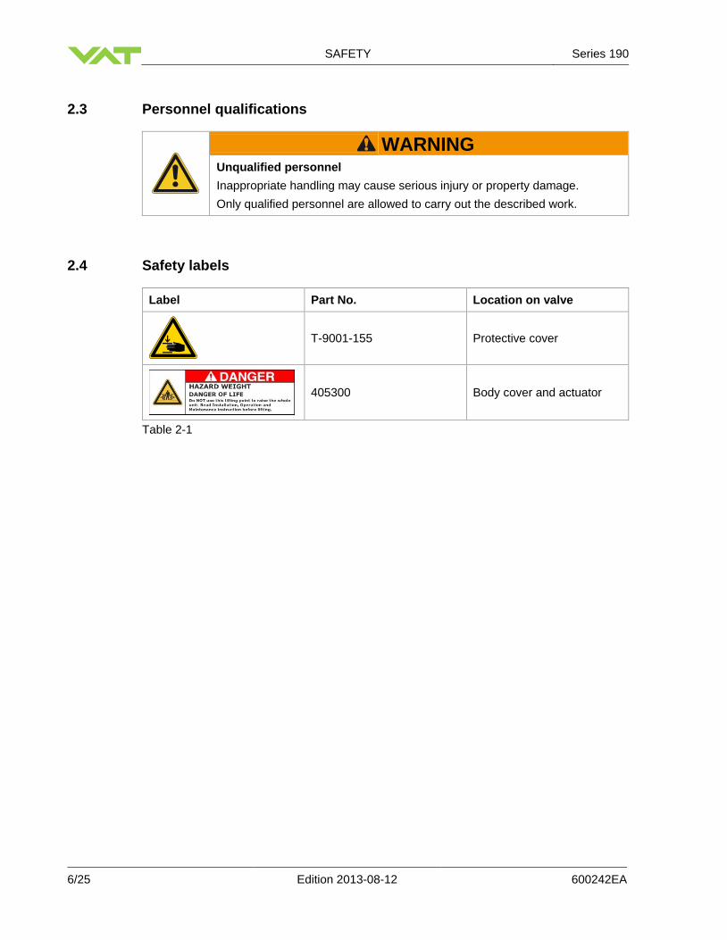
2.3 Personnel qualifications
WARNING Unqualified personnel
Inappropriate handling may cause serious injury or property damage.
Only qualified personnel are allowed to carry out the described work.
2.4 Safety labels
Label Part No. Location on valve
T-9001-155 Protective cover
405300 Body cover and actuator
Table 2-1

Series 190 DESIGN AND FUNCTION
600242EA Edition 2013-08-12 7/25
3 Design and Function
3.1 Design
1 Sealing surface
2 Body lower part
3 Body upper part
4 Actuator
Figure 3-1
3.2 Function
The valve features the VATLOCK sealing technology. This means, the valve is mechani-cally locked in the closed position. In the open position, the mechanism is not locked. Leaf springs hold gate and counter plate against the carriage with the ball retainers. The ball pairs are in the detents. For closing, the mechanism is moved forward into the closing position. The locking starts after the leaf spring stop touches the body. The ball retainers move the ball pairs out of the detents. Gate and counter plate are spread apart. The gate seal is pressed against the sealing surface without scuffing. The arrangement of the ball pairs ensures an increase of the sealing force with vacuum on either side of the gate. During opening the movements proceed in the reverse order; see «Figure 3-2».
1 Valve gate
2 Counter-plate
3 Leaf springs
4 Ball pairs
5 Ball detents
6 Gate seal
7 Spring stop
Figure 3-2
+0.10+0.30
-0.30-0.10
ISO 13715
Sauberkeitsstufe 1 = mediumberührend
Front Page Design
1
3
1 Sealing surface2 Body lower part3 Body upper part4 Actuator
2
4Unpacking
Unpacking (2)
1
2
3
1 Flange A2 Flange B3 Screws
1
2
3
4
5
6
7
Maintenace
1 Lifting ropes2 Load Ring3 Screws / Pins4 Body upper part5 Bonnet seal6 Bearings7 Body lower part
900-1250
1:20
575397 Blatt /
Werkstoff Bez.Datum
VAT-Artikelnummer
VAT Vakuumventile AG
Index
höchste Nr.
Gezeichnet
Massstab
Oberfl. [mm2]
Zünd R.
Gewicht [kg]
-
1
Zeichnung für MBA
---
3D Modellnummer
25.01.13
All
e V
AT
-No
rmd
ok
um
ente
, au
f d
ie i
n d
iese
r Z
eich
nu
ng
verw
iese
n w
ird
, st
eh
en
au
f d
er
Inte
rnets
eit
e
ww
w.v
at.i
nfo
zu
r V
erfÃ
¼g
un
g. S
ie d
ü
rfen
nu
r im
Zu
sam
men
han
g m
it d
iese
r Z
eich
nu
ng
ver
wen
det
wer
den
.
1634.861
575394
Kun
denn
umm
er
Werkstoff Nr.Gewindedarstellung
A2 232732
Die
se Z
eic
hnung b
leib
t unse
r geis
tiges
Eig
entu
m.
Sie
darf
ohne u
nse
re s
chri
ftli
che E
inw
illi
gung
weder
kopie
rt,
verv
ielf
ält
igt
noch d
ritt
en P
er-
son
en m
itg
etei
lt o
der
zu
gÃ
¤n
gli
ch g
emac
ht
wer
den
.
nach VAT Norm N-1016
Index-Zch.Nr.
190
CH-9469 Haag , Switzerland
Tel +41 81 7716161 Fax +41 81 7714830
Index
P rojekt i on E-
Ursprung
= Q-MerkmalsbezeichnungStatus
R DN
Zeichnungsnummer
59639951.24
19062-PE44-0003 A
In Arbeit
IN ARBEIT1
1 2 3 4 5 6 7 8 9 10 11
A
B
C
D
E
F
G
H
Tole
rier
ungs
grun
dsat
z IS
O 80
15:
Unab
hän
gigk
eits
prin
zip
---
kein
e

INSTALLATION Series 190
8/25 Edition 2013-08-12 600242EA
4 Installation
WARNING Unqualified personnel
Inappropriate handling may cause serious injury or property damage.
Only qualified personnel are allowed to carry out the described work.
WARNING Heavy weight
Physical overstraining.
Use a crane to lift the product.
4.1 Unpacking
Make sure that the supplied products are in accordance with your order.
Inspect the quality of the supplied products visually. If it does not meet your requirements, please contact VAT immediately.
Store the original packaging material. It may be useful if products must be returned to VAT.
The valve can be lifted only at the load rings threats; see «Figure 4-1» below.
1 Load ring for valve lifting
Figure 4-1
+0.10+0.30
-0.30-0.10
ISO 13715
Sauberkeitsstufe 1 = mediumberührend
Front Page Design
1
3
1 Sealing surface2 Body lower part3 Body upper part4 Actuator
2
4Unpacking
Unpacking (2)
1
2
3
1 Flange A2 Flange B3 Screws
1
2
3
4
5
6
7
Maintenace
1 Lifting ropes2 Load Ring3 Screws / Pins4 Body upper part5 Bonnet seal6 Bearings7 Body lower part
900-1250
1:20
575397 Blatt /
Werkstoff Bez.Datum
VAT-Artikelnummer
VAT Vakuumventile AG
Index
höchste Nr.
Gezeichnet
Massstab
Oberfl. [mm2]
Zünd R.
Gewicht [kg]
-
1
Zeichnung für MBA
---
3D Modellnummer
25.01.13
All
e V
AT
-Norm
do
ku
men
te, a
uf
die
in
die
ser
Zei
chn
un
g
verw
iese
n w
ird
, st
eh
en
au
f d
er
Inte
rnets
eit
e
ww
w.v
at.i
nfo
zu
r V
erfÃ
¼g
un
g. S
ie d
ü
rfen
nu
r im
Zu
sam
men
han
g m
it d
iese
r Z
eich
nu
ng
ver
wen
det
wer
den
.
1634.861
575394
Kun
denn
umm
er
Werkstoff Nr.Gewindedarstellung
A2 232732
Die
se Z
eic
hnung b
leib
t unse
r geis
tiges
Eig
entu
m.
Sie
darf
ohne u
nse
re s
chri
ftli
che E
inw
illi
gung
weder
kopie
rt,
verv
ielf
ält
igt
noch d
ritt
en P
er-
son
en m
itget
eilt
oder
zug
än
gli
ch g
emac
ht
wer
den
.
nach VAT Norm N-1016
Index-Zch.Nr.
190
CH-9469 Haag , Switzerland
Tel +41 81 7716161 Fax +41 81 7714830
Index
P rojekt i on E-
Ursprung
= Q-MerkmalsbezeichnungStatus
R DN
Zeichnungsnummer
59639951.24
19062-PE44-0003 A
In Arbeit
IN ARBEIT1
1 2 3 4 5 6 7 8 9 10 11
A
B
C
D
E
F
G
H
Tole
rier
ungs
grun
dsat
z IS
O 80
15:
Unab
hän
gigk
eits
prin
zip
---
kein
e
1

Series 190 INSTALLATION
600242EA Edition 2013-08-12 9/25
4.2 Installation into the system
WARNING Movable parts
Human body parts may get jammed and severely injured.
Do not connect or supply electrical power and compressed air before the product is completely mounted in the system.
NOTICE Contamination
Product may get contaminated.
Always wear cleanroom gloves when handling the product.
NOTICE Inappropriate tools
Sealing surfaces may get damaged.
Do not use sharp-edged tools.
NOTICE Wrong tightening torque
Valve body and screws may get damaged.
Use tightening torque according the size of the screws.
NOTICE Too long screws
Valve body may get deformed and / or malfunctions may occur.
Use only screws recommended by VAT.
1. Remove protective covers from body flanges.
2. Clean sealing surfaces and seals of both flanges; see (1) and (2) according to «Figure 4-2» on page 10.
The valve seat side is marked with the symbol « » on flange «A».
3. Lift the valve to the mounting position, use only the load rings; see «Figure 4-1» on
page 8.
4. Mount the four screws (3) according to «Figure 4-2» on page 10, evenly in crosswise order until the seal touches the sealing surface.

INSTALLATION Series 190
10/25 Edition 2013-08-12 600242EA
5. Tighten all screws with the torques appropriate for their property classes.
1 Flange A
2 Flange B
3 Screws
Figure 4-2 4.2.1 Admissible forces and bending moments
Forces from evacuating the system, from the weight of other components or from baking can lead to deformation of the valve body and to malfunction of the valve. The stress has to be relieved by suitable means; see «Table 4-1» below.
The following forces or bending moments are admissible:
DN (nom. I.D.) Axial tensile or com-pressive force «FA»
Bending moment «M»
mm inch N lbf Nm lbf ∙ ft
900 36 9800 2200 1274 940
1000 40 9800 2200 1372 1015
1250 50 9800 2200 1470 1090
If a combination of both forces («FA» and «M») occurs, the values mentioned above are invalid. Please contact VAT for more information.
Table 4-1
+0.10+0.30
-0.30-0.10
ISO 13715
Sauberkeitsstufe 1 = mediumberührend
Front Page Design
1
3
1 Sealing surface2 Body lower part3 Body upper part4 Actuator
2
4Unpacking
Unpacking (2)
1
2
3
1 Flange A2 Flange B3 Screws
1
2
3
4
5
6
7
Maintenace
1 Lifting ropes2 Load Ring3 Screws / Pins4 Body upper part5 Bonnet seal6 Bearings7 Body lower part
900-1250
1:20
575397 Blatt /
Werkstoff Bez.Datum
VAT-Artikelnummer
VAT Vakuumventile AG
Index
höchste Nr.
Gezeichnet
Massstab
Oberfl. [mm2]
Zünd R.
Gewicht [kg]
-
1
Zeichnung für MBA
---
3D Modellnummer
25.01.13
All
e V
AT
-Norm
dok
um
ente
, au
f die
in d
iese
r Z
eich
nun
g
verw
iese
n w
ird
, st
eh
en
au
f d
er
Inte
rnets
eit
e
ww
w.v
at.i
nfo
zu
r V
erfÃ
¼g
un
g. S
ie d
ü
rfen
nu
r im
Zu
sam
men
han
g m
it d
iese
r Z
eich
nu
ng
ver
wen
det
wer
den
.
1634.861
575394
Kun
denn
umm
er
Werkstoff Nr.Gewindedarstellung
A2 232732
Die
se Z
eic
hnung b
leib
t unse
r geis
tiges
Eig
entu
m.
Sie
darf
ohne u
nse
re s
chri
ftli
che E
inw
illi
gung
weder
kopie
rt,
verv
ielf
ält
igt
noch d
ritt
en P
er-
sonen
mit
get
eilt
oder
zugÃ
¤ng
lich
gem
acht
wer
den
.
nach VAT Norm N-1016
Index-Zch.Nr.
190
CH-9469 Haag , Switzerland
Tel +41 81 7716161 Fax +41 81 7714830
Index
P rojekt i on E-
Ursprung
= Q-MerkmalsbezeichnungStatus
R DN
Zeichnungsnummer
59639951.24
19062-PE44-0003 A
In Arbeit
IN ARBEIT1
1 2 3 4 5 6 7 8 9 10 11
A
B
C
D
E
F
G
H
Tole
rier
ungs
grun
dsat
z IS
O 80
15:
Unab
hän
gigk
eits
prin
zip
---
kein
e
FA M

Series 190 INSTALLATION
600242EA Edition 2013-08-12 11/25
4.3 Compressed air connection
WARNING Valve in open position
Risk of injury when compressed air is connected to the valve.
Connect compressed air only when: – valve is installed in the vacuum system – moving parts cannot be touched
Use clean, dry or slightly oiled air only.
Admissible air pressure range, see product data sheet.
1. Connect compressed air according to the product data sheet and dimensional drawing.
4.4 Electrical connection
DANGER Electric shock
Parts being under voltage will result in serious injury or death.
Do not touch parts being under voltage.
NOTICE Wrong voltage
Electrical components may get damaged.
Supply electrical components with the correct voltage.
1. Connect solenoid valve according to the product data sheet and dimensional drawing.
2. Connect position indicator according to the product data sheet and dimensional drawing.

OPERATION Series 190
12/25 Edition 2013-08-12 600242EA
5 Operation
WARNING Unqualified personnel
Inappropriate handling may cause serious injury or property damage.
Only qualified personnel are allowed to carry out the described work.
WARNING Movable parts
Human body parts may get jammed and severely injured.
Do not operate before product is installed completely into the vacuum system.
5.1 Normal operation
Valve is opened and closed pneumatically.
5.2 Operation under increased temperature
Maximum allowed temperature, see product data sheet.
5.3 Behavior in case of compressed air pressure drop
See product data sheet.
5.4 Behavior in case of power failure
See product data sheet. 5.4.1 Manual emergency operation
WARNING Movable parts
Human body parts may get jammed and severely injured.
Keep human body parts away from movable parts.

Series 190 OPERATION
600242EA Edition 2013-08-12 13/25
Standard solenoid valve
To open the valve: Push and turn the slotted screw (1) clockwise to its stop.
To close the valve: Turn the slotted screw (1) counter-clockwise to its stop.
1 Slotted screw
Figure 5-1
For remote operation make sure that the slotted screw is turned counter-clockwise to its stop.
Impulse solenoid valve
To close the valve: Push the button (3) – coil CLOSE
To open the valve: Push the button (2) – coil OPEN
1 Coil OPEN
2 Button of coil OPEN
3 Button of coil CLOSE
4 Coil CLOSE
Figure 5-2

OPERATION Series 190
14/25 Edition 2013-08-12 600242EA
5.5 Trouble shooting
Failure Check Action See
Valve does not close / open
Air pressure Connect compressed air
«4.3 Compressed air connection»
Operating pressure
Adjust operating pressure
Product data sheet
Voltage at solenoid valve
Connect voltage «4.4 Electrical connection»
Leak at gate Gate seal all right?
Replace gate seal
«6.3 Replacement of valve gate seal / bonnet seal»
Gate damaged or contaminated?
Contact VAT www.vatvalve.com
Operating pressure
Adjust operating pressure
Product data sheet
Leak at body Bonnet seal and sealing surface all right?
Clean sealing surface, if necessary, replace bonnet seal
«6.3 Replacement of valve gate seal / bonnet seal»
Table 5-1
If you need any further information, please contact one of our service centers. You will find the addresses on our website www.vatvalve.com.

Series 190 MAINTENANCE
600242EA Edition 2013-08-12 15/25
6 Maintenance
WARNING Unqualified personnel
Inappropriate handling may cause serious injury or property damage.
Only qualified personnel are allowed to carry out the described work.
WARNING Heavy weight
Physical overstraining.
Use a crane to lift the valve insert.
WARNING Hazardous components
Human body parts may get jammed and severely injured.
Before starting maintenance: – disconnect compressed air supply – disconnect electrical power supply
WARNING Movable parts
Human body parts may get jammed and severely injured.
Keep human body parts away from movable parts.
6.1 Maintenance intervals
Under clean operating conditions the valve does not require any maintenance until 10 000 cycles; see product data sheet. After these cycles, VAT recommends to get in contact with the service center.
For more information or a general overhaul please contact one of our service centers. You will find the addresses on our website www.vatvalve.com.
6.2 Required tools
Torque wrench
Cleanroom wiper soaked with alcohol (2% methyl ethyl ketone)

MAINTENANCE Series 190
16/25 Edition 2013-08-12 600242EA
6.3 Replacement of valve gate seal / bonnet seal
WARNING Loaded spring steel sheet
Human body parts may get jammed and severely injured.
Do not put human body parts between valve gate and spring steel sheet.
NOTICE Contamination
Product may get contaminated.
Always wear cleanroom gloves when handling the product.
NOTICE Inappropriate tools
Sealing surfaces may get damaged.
Do not use sharp-edged tools.
1 Lifting ropes
2 Load ring
3 Body cover screws / pins
4 Bonnet seal
5 Body lower part
6 Bearings
7 Body upper part
Figure 6-1
+0.10+0.30
-0.30-0.10
ISO 13715
Sauberkeitsstufe 1 = mediumberührend
Front Page Design
1
3
1 Sealing surface2 Body lower part3 Body upper part4 Actuator
2
4Unpacking
Unpacking (2)
1
2
3
1 Flange A2 Flange B3 Screws
1
2
3
4
5
6
7
Maintenace
1 Lifting ropes2 Load Ring3 Screws / Pins4 Body upper part5 Bonnet seal6 Bearings7 Body lower part
900-1250
1:20
575397 Blatt /
Werkstoff Bez.Datum
VAT-Artikelnummer
VAT Vakuumventile AG
Index
höchste Nr.
Gezeichnet
Massstab
Oberfl. [mm2]
Zünd R.
Gewicht [kg]
-
1
Zeichnung für MBA
---
3D Modellnummer
25.01.13
All
e V
AT
-No
rmd
ok
um
ente
, au
f d
ie i
n d
iese
r Z
eich
nu
ng
verw
iese
n w
ird
, st
eh
en
au
f d
er
Inte
rnets
eit
e
ww
w.v
at.i
nfo
zu
r V
erfÃ
¼g
un
g. S
ie d
ü
rfen
nu
r im
Zu
sam
men
han
g m
it d
iese
r Z
eich
nu
ng
ver
wen
det
wer
den
.
1634.861
575394
Kun
denn
umm
er
Werkstoff Nr.Gewindedarstellung
A2 232732
Die
se Z
eic
hnung b
leib
t unse
r geis
tiges
Eig
entu
m.
Sie
darf
ohne u
nse
re s
chri
ftli
che E
inw
illi
gung
weder
kopie
rt,
verv
ielf
ält
igt
noch d
ritt
en P
er-
son
en m
itg
etei
lt o
der
zu
gÃ
¤n
gli
ch g
emac
ht
wer
den
.
nach VAT Norm N-1016
Index-Zch.Nr.
190
CH-9469 Haag , Switzerland
Tel +41 81 7716161 Fax +41 81 7714830
Index
P rojekt i on E-
Ursprung
= Q-MerkmalsbezeichnungStatus
R DN
Zeichnungsnummer
59639951.24
19062-PE44-0003 A
In Arbeit
IN ARBEIT1
1 2 3 4 5 6 7 8 9 10 11
A
B
C
D
E
F
G
H
Tole
rier
ungs
grun
dsat
z IS
O 80
15:
Unab
hän
gigk
eits
prin
zip
---
kein
e

Series 190 MAINTENANCE
600242EA Edition 2013-08-12 17/25
1. Vent chambers on either side to atmospheric pressure.
2. Open the valve.
3. Disconnect electrical power supply.
4. Remove the screws (3) from the body upper part (7) in crosswise order; see «Figure 6-1» on page 16.
5. Lift actuator / mechanism unit carefully from body without touching the body wall and sealing surfaces.
Do not touch the actuator with the lifting ropes, if you lift the actuator + mechanism out of the valve body!
6. Move the mechanism unit with the body upper part to a clean, safe table for
maintenance.
7. Disconnect compressed air supply.
8. If the mechanism unit is out of the valve body you have the opportunity to clean the mechanism unit with alcohol.
9. If the O-rings at the gate and the bonnet flange are not damaged you should clean them with cleanroom wiper.
Do not clean the O-ring with alcohol, because alcohol may damage the surface of the O-rings, we recommend to treat the O-rings with a small amount of vacuum grease.
10. If the O-rings at the gate unit and the bonnet flange are damaged, they have to be
changed.
11. Take out the gate O-ring with the O-ring removal tool.
12. Put some slight vacuum grease on the new gate O-ring.
13. Put in the new gate O-ring into the gate groove.
14. Take out the bonnet O-ring.
15. Put some slight vacuum grease on the new bonnet O-ring.
16. Put in the new bonnet O-ring into the bonnet flange groove.
17. Connect compressed air supply and put air on bring the mechanism into open position.
18. Lift the actuator / mechanism unit back into the valve body and do not touch any sealing surfaces.
19. Tighten the screws (3) from the body upper part (7) in crosswise order with the correct tightening torque.

MAINTENANCE Series 190
18/25 Edition 2013-08-12 600242EA
20. Connect electrical power supply.
21. Close the valve.
Valve is ready for use.

Series 190 REPAIRS
600242EA Edition 2013-08-12 19/25
7 Repairs
Repairs may only be carried out by the VAT service staff. In exceptional cases, the customer is allowed to carry out the repairs, but only with the prior consent of VAT. Please contact one of our service centers. You will find the addresses on our website www.vatvalve.com.

DISMOUNTING AND STORAGE Series 190
20/25 Edition 2013-08-12 600242EA
8 Dismounting and Storage
WARNING Unqualified personnel
Inappropriate handling may cause serious injury or property damage.
Only qualified personnel are allowed to carry out the described work.
WARNING Heavy weight
Physical overstraining.
Use a crane to lift the product.
WARNING Hazardous components
Human body parts may get jammed and severely injured.
Before dismounting the product – disconnect compressed air supply – disconnect electrical power supply
WARNING Movable parts
Human body parts may get jammed and severely injured.
Keep human body parts away from movable parts.
NOTICE Contamination
Product may get contaminated.
Always wear cleanroom gloves when handling the product.

Series 190 DISMOUNTING AND STORAGE
600242EA Edition 2013-08-12 21/25
8.1 Dismounting
NOTICE Valve in open position
Valve mechanism may get damaged if valve is in open position.
Close valve before dismounting the valve from the system.
1. Close valve.
2. Carry out the steps according to chapter «4 Installation» in reverse order. Pay attention to the safety instructions!
8.2 Storage
NOTICE Wrong storage
Inappropriate temperatures and humidity may cause damage to the product.
Valve must be stored at: – relative humidity between 10% and 70% – temperature between +10 °C and +50 °C – non-condensing environment
NOTICE Inappropriate packaging
Product may get damaged if inappropriate packaging material is used.
Always use the original packaging material and handle product with care.
1. Clean / decontaminate valve.
2. Cover all valve openings with a protective foil.
3. Pack valve appropriately, by using the original packaging material.

PACKAGING AND TRANSPORT Series 190
22/25 Edition 2013-08-12 600242EA
9 Packaging and Transport
WARNING Unqualified personnel
Inappropriate handling may cause serious injury or property damage.
Only qualified personnel are allowed to carry out the described work.
WARNING Heavy weight
Physical overstraining.
Use a crane to lift the product.
WARNING Harmful substances
Risk of injury in case of contact with harmful substances.
Remove harmful substances (e. g. toxic, caustic or microbiological ones) from valve before you return the valve to VAT.
NOTICE Inappropriate packaging
Product may get damaged if inappropriate packaging material is used.
Always use the original packaging material and handle product with care.
When returning products to VAT, please fill out the VAT form «Declaration
of Chemical Contamination» and send it to VAT in advance. The form can be downloaded from our website www.vatvalve.com.
If products are radioactively contaminated, the VAT form «Contamination and Radiation Report» must be filled out. Please contact VAT in advance.
If products are sent to VAT in contaminated condition, VAT will carry out the decontamination procedure at the customer's expense.
Series 190 PACKAGING AND TRANSPORT
600242EA Edition 2013-08-12 23/25
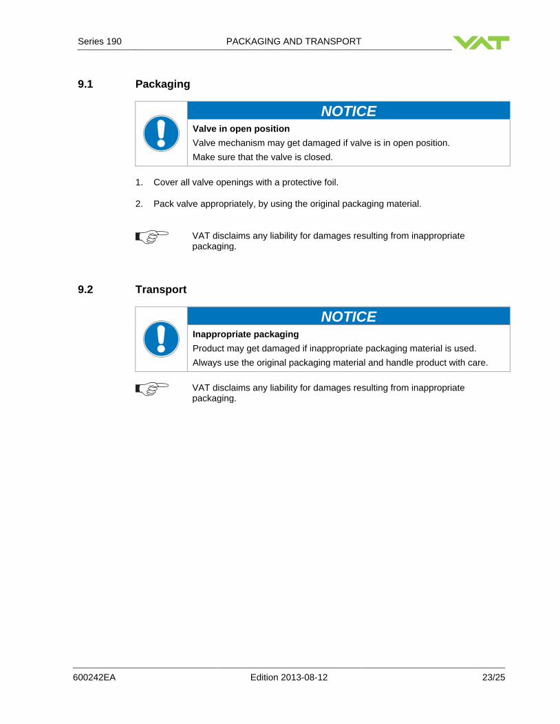
9.1 Packaging
NOTICE Valve in open position
Valve mechanism may get damaged if valve is in open position.
Make sure that the valve is closed.
1. Cover all valve openings with a protective foil.
2. Pack valve appropriately, by using the original packaging material.
VAT disclaims any liability for damages resulting from inappropriate packaging.
9.2 Transport
NOTICE Inappropriate packaging
Product may get damaged if inappropriate packaging material is used.
Always use the original packaging material and handle product with care.
VAT disclaims any liability for damages resulting from inappropriate packaging.

DISPOSAL Series 190
24/25 Edition 2013-08-12 600242EA
10 Disposal
WARNING Harmful substances
Environmental pollution.
Discard products and parts according to the local regulations.

Series 190 SPARE PARTS
600242EA Edition 2013-08-12 25/25
11 Spare parts
NOTICE Non-original spare parts
Non-original spare parts may cause damage to the product.
Use original spare parts from VAT only.
Please specify the fabrication number of the product when you place an
order for spare parts; see chapter «1.1 Identification of product». This is to ensure that the appropriate spare parts are supplied.
VAT makes a difference between spare parts that may be replaced by the customer and those that need to be replaced by the VAT service staff.
«Table 11» only contains spare parts that may be replaced by the customer. If you need any other spare parts, please contact one of our service centers. You will find the addresses on our website www.vatvalve.com.
Description Part No.
Quantity per valve
Maintenance procedure see chapter
Seal kit On request 1
«6.3 Replacement of valve gate seal / bonnet seal»
Gate O-ring On request 1 «6.3 Replacement of valve gate seal / bonnet seal»
Bonnet flange O-ring On request 1 «6.3 Replacement of valve gate seal / bonnet seal»
Table 11