Folding Cartons - mdcdn01-9b10.kxcdn.com€¦ · Folding Cartons 100

PN : 500-5-0007 (2011) SERIAL # 3280 - 3367
FOLDING DEFOLIATOR
OPERATOR’S MANUAL
2011SERIAL # 3280 - 3367

PN : 500-5-0007 (2011)SERIAL # 3280 - 3367
TO THE DEALER:
Assembly and proper installation of this product is the responsibility of the Alloway dealer. Read manual instructions and safety rules. Make sure all items on the Dealer’s Pre-Delivery and Delivery Check Lists in the Operator’s Manual are completed before releasing equipment to the owner.
The dealer must complete the Warranty Registration included in this manual. Both dealer and customer must sign the registration which certifies that all Dealer Check List items have been completed. The dealer is to return the prepaid postage portion to Alloway, give one copy to the customer, and retain one copy. Note: Warranty credit is subject to this form being completed and returned.
TO THE OWNER:
Read this manual before operating your Alloway equipment. The information presented will prepare you to do a better and safer job. Keep this manual handy for ready reference. Require all operators to read this manual carefully and become acquainted with all the adjustment and operating procedures before attempting to operate. Replacement manuals can be obtained from your dealer.
The equipment you have purchased has been carefully engineered and manufactured to provide dependable and satisfactory use. Like all mechanical products, it will require cleaning and upkeep. Lubricate the unit as specified. Observe all safety information in this manual and safety decals on the equipment.
For service, your authorized Alloway dealer has trained mechanics, genuine Alloway service parts, and the necessary tools and equipment to handle all your needs.
Use only genuine Alloway service parts. Substitute parts will void the warranty and may not meet standards required for safe and satisfactory operation. Record the model number and serial number of your equipment in the spaces provided:
Model:_________________________ Date of Purchase _____________________________
Serial Number: (see Safety Decal section for location) __________________________________
Provide this information to your dealer to obtain correct repair parts.
Throughout this manual, the term IMPORTANT is used to indicate that failure to observe can cause damage to equipment. The terms CAUTION, WARNING and DANGER are used in conjunction with the Safety-Alert Symbol, (a triangle with an exclamation mark), to indicate the degree of hazard for items of personal safety.
IMPORTANT Indicates that failure to observe can cause damage to equipment.
NOTE Indicates helpful information.
This Safety-Alert Symbol indicates a hazard and means ATTENTION! BECOME ALERT! YOUR SAFETY IS INVOLVED!
Indicates a potentially hazardous situation that, if not avoided, could result in death or serious injury, and includes hazards that are exposed when guards are removed
WARNING
Indicates a potentially hazardous situation that, if not avoided, may result in minor or moderate injury.CAUTION
Indicates an imminently hazardous situation that, if not avoided, will result in death or serious injury.
1PN : 500-5-0007 (2011) SERIAL # 3280 - 3367
The purpose of this manual is to assist you in operating and maintaining your Beet Defoliator. Read it carefully. It furnishes information and instructions that will help you achieve years of dependable performance. These instructions have been compiled from extensive field experience and engineering data. Some information may be general in nature due to unknown and varying operating conditions. However, through experience and these instructions, you should be able to develop procedures suitable to your particular situation.
The illustrations and data used in this manual were current at the time of printing, but due to possible inline production changes, your machine may vary slightly in detail. We reserve the right to redesign and change the machines as may be necessary without notification.
WARNING
� Some illustrations in this manual show the Beet Defoliator with safety shields removed to provide a better view. The Beet Defoliator should never be operated with any safety shielding removed.
Throughout this manual, references are made to right and left direction. These are determined by standing behind the equipment facing the direction of forward travel.
INTRODUCTION ....................................................................................................................... Inside Front Cover
GENERAL INFORMATION .................................................................................................................................... 1
SAFETY RULES ............................................................................................................................................... 3 - 7
CHECK LISTS (DEALER’S RESPONSIBILITY) ................................................................................................... 8
OPERATOR SIGN-OFF RECORD ........................................................................................................................ 9
SAFETY DECALS ........................................................................................................................................ 10 - 13
OPERATION ................................................................................................................................................. 15 - 28
OWNER SERVICE ....................................................................................................................................... 29 - 33
TROUBLE SHOOTING ....................................................................................................................................... 34
INDEX TO PARTS LISTS .................................................................................................................................... 35
BOLT TORQUE CHART ...................................................................................................................................... 81
ABBREVIATIONS ................................................................................................................................................ 82
INDEX .................................................................................................................................................................. 83
REPLACEMENT PARTS WARRANTY ................................................................................................................ 84
PRODUCT WARRANTY ............................................................................................................ Inside Back Cover
TABLE OF CONTENTS
GENERAL INFORMATION
PN : 500-5-0007 (2011)2SERIAL # 3280 - 3367
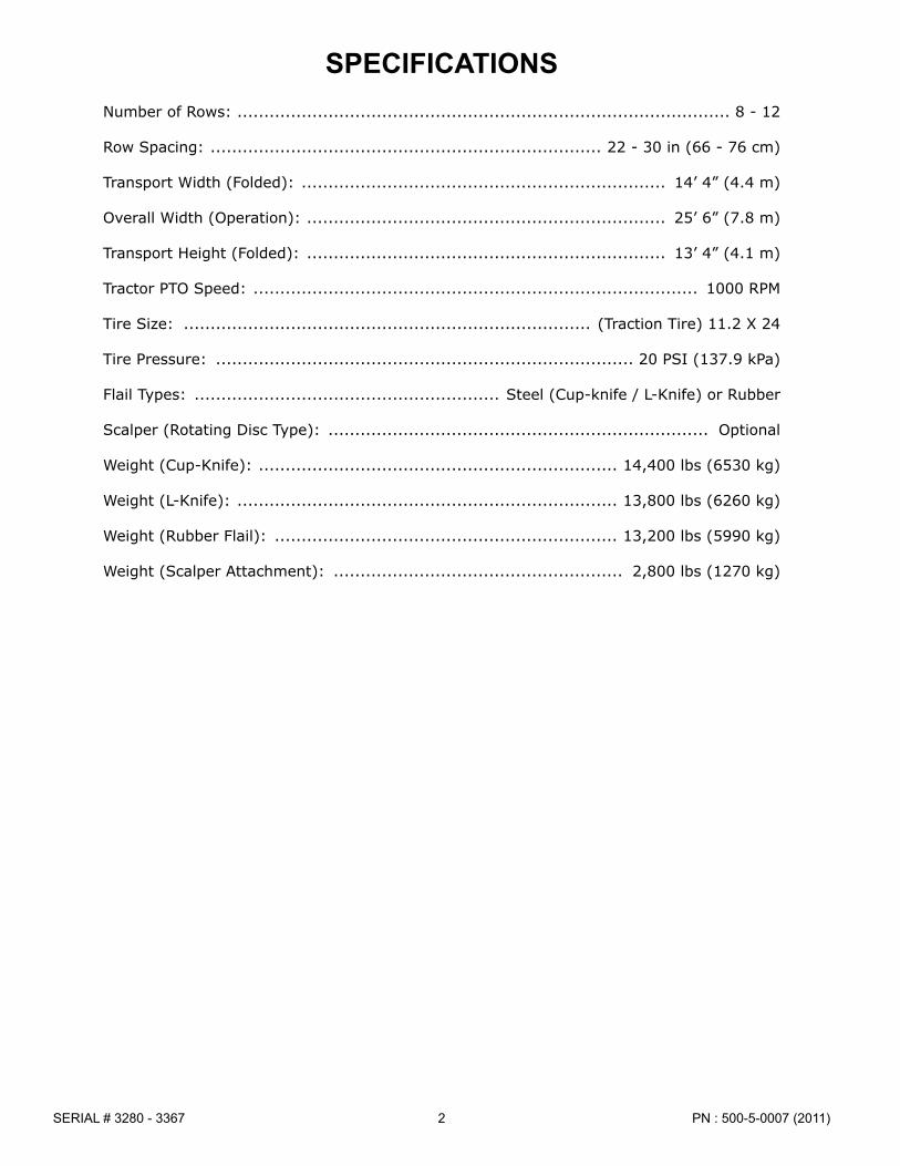
Number of Rows: �������������������������������������������������������������������������������������������� 8 - 12
Row Spacing: ������������������������������������������������������������������������� 22 - 30 in (66 - 76 cm)
Transport Width (Folded): �������������������������������������������������������������������� 14’ 4” (4�4 m)
Overall Width (Operation): ������������������������������������������������������������������� 25’ 6” (7�8 m)
Transport Height (Folded): ������������������������������������������������������������������� 13’ 4” (4�1 m)
Tractor PTO Speed: ����������������������������������������������������������������������������������� 1000 RPM
Tire Size: ���������������������������������������������������������������������������� (Traction Tire) 11�2 X 24
Tire Pressure: ������������������������������������������������������������������������������ 20 PSI (137�9 kPa)
Flail Types: ��������������������������������������������������������� Steel (Cup-knife / L-Knife) or Rubber
Scalper (Rotating Disc Type): ����������������������������������������������������������������������� Optional
Weight (Cup-Knife): ������������������������������������������������������������������� 14,400 lbs (6530 kg)
Weight (L-Knife): ����������������������������������������������������������������������� 13,800 lbs (6260 kg)
Weight (Rubber Flail): ���������������������������������������������������������������� 13,200 lbs (5990 kg)
Weight (Scalper Attachment): ������������������������������������������������������ 2,800 lbs (1270 kg)
SPECIFICATIONS

3PN : 500-5-0007 (2011) SERIAL # 3280 - 3367
Safety is a primary concern in the design and manufacture of our products. Unfortunately, our efforts to provide safe equipment can be wiped out by a single careless act of an operator.
In addition to the design and configuration of equipment, hazard control and accident preven tion are dependent upon the awareness, con cern, prudence and proper training of personnel involved in the operation, transport, maintenance and storage of equipment.
It has been said “The best safety device is an informed, careful operator.” We ask you to be that kind of an operator.
TRAINING
� Safety instructions are important! Read all attachment and power unit manuals; follow all safety rules and safety decal information. (Replacement manuals are available from dealer). Failure to follow instructions or safety rules can result in serious injury or death.
� If you do not understand any part of this manual and need assistance, see your dealer.
� Know your controls and how to stop engine and attachment quickly in an emer gency.
� Operators must be instructed in and be capable of the safe operation of the equip ment, its attachments and all controls. Do not allow anyone to operate this equip ment without proper instructions.
� Keep hands and body away from pres surized lines. Use paper or cardboard, not body parts to check for leaks. Wear safety goggles. Hydraulic fluid under pressure can easily penetrate skin and will cause serious injury or death.
� Make sure that all operating and service personnel know that in the event hydraulic fluid penetrates skin, it must be surgically removed as soon as possible by a doctor familiar with this form of injury, or gangrene, serious injury or death will result. CONTACT A PHYSICIAN IMMEDI ATELY IF FLUID ENTERS SKIN OR EYES. DO NOT DELAY.
� Never allow children or untrained persons to operate equipment.
__________________________________________
PREPARATION � Check that all hardware is tight and properly
installed. Always tighten to torque chart specifications unless instructed otherwise in this manual.
� Air in hydraulic systems can cause erratic operation and allows loads or equip ment components to drop unexpectedly. Before operating or allowing anyone to approach the equipment, purge any air in the system by operating all hydraulic functions several times after connecting equipment, connecting hoses, or doing any hydraulic maintenance.
� Make sure all hydraulic hoses, fittings and valves are in good condition and not leaking before starting power unit or using equipment. Check and route hoses care fully to prevent damage. Hoses must not be twisted, bent sharply, kinked, frayed, pinched, or come into contact with any moving parts. Operate moveable compo nents through full operational range to check clearances. Replace any damaged hoses immediately.
� Always wear relatively tight and belted clothing to avoid entanglement in moving parts. Wear sturdy, rough-soled work shoes and protective equipment for eyes, hair, hands, hearing and head; and respirator or filter mask where appropriate.
� Ensure implement is properly attached, adjusted and in good operating condition.
� Make sure spring-activated locking pin or collar slides freely and is seated firmly in tractor PTO spline groove.
� Before starting power unit, check all equip-ment driveline guards for damage and make sure they rotate freely on all drivelines. Re place any damaged guards. If guards do not rotate freely on drivelines, repair and re place bearings before operating.
The designed and tested safety of this equipment depends on it being operated within the limitations as explained in this manual.
SAFETY RULESATTENTION! BECOME ALERT! YOUR SAFETY IS INVOLVED!
(Safety Rules continued on next page)
PN : 500-5-0007 (2011)4SERIAL # 3280 - 3367
� Power unit must be equipped with ROPS or ROPS CAB and seat belt. Keep seat belt securely fastened. Falling off power unit can result in death from being run over or crushed. Keep foldable ROPS systems in “locked up” position at all times.
� Connect PTO driveline directly to power unit PTO shaft. Never use adapter sleeves or adapter shafts. Adapters can cause driveline failures due to incorrect spline or incorrect operating length and can result in personal injury or death.� Inspect rubber flaps and swing rod before each use. Replace if damaged or missing. Flaps must pivot and hang freely so there are no gaps. Do not put equipment into service until repaired.
� Remove accumulated debris from this equipment, tractor and engine to avoid fire hazard.
� Ensure all safety decals are installed. Replace if damaged. (See Safety Decals section for location.)
� Ensure shields and guards are properly installed and in good condition. Replace if damaged.
� A minimum 20% of tractor and equipment weight must be on tractor front wheels when attachments are in transport position. Without this weight, tractor could tip over, causing personal injury or death. The weight may be attained with a loader, front wheel weights, ballast in tires or front tractor weights. When attaining the minimum 20% weight on the front wheels, you must not exceed the Roll Over Protection Structure (ROPS) weight certification. Weigh the tractor and equipment. Do not estimate.
� Make sure hydraulic hoses and cylinders are fully purged of air before operating. Keep all persons away and fill the system by raising and lowering all functions several times. Air in the system can allow components to fall unexpectedly.
� Inspect and clear area of stones, branches, or other hard objects that might be thrown, causing injury or damage.
TRANSPORTING � Power unit must be equipped with ROPS
or ROPS cab and seat belt. Keep seat belt securely fastened. Falling off power unit can result in death from being run over or crushed. Keep foldable ROPS systems in “locked up” position at all times.
� Always sit in power unit seat when operating controls or starting engine. Securely fasten seat belt, place transmission in neutral, engage brake, and ensure all other controls are disengaged before starting power unit engine.
� A minimum 20% of tractor and equipment weight must be on the tractor front wheels when attachments are in transport position. Without this weight, tractor could tip over, causing personal injury or death. The weight may be attained with a loader, front wheel weights, ballast in tires or front tractor weights. Weigh the tractor and equipment. Do not estimate.
� Always attach safety chain to tractor drawbar when transporting unit.
� Always raise unit and install transport locks before transporting. Leak down or failure of mechanical or hydraulic system can cause equip ment to drop.
� Never exceed 20 MPH during transport. See the Speed vs. Weight Ratio Table in "Field Operation, Transporting the Unit" for proper tow vehicle to machine weight ratios.
� Watch for hidden hazards on the terrain.
� Always comply with all state and local lighting and marking requirements.
� Never allow riders on power unit or attachment.
� Do not operate PTO during transport.
� Look down and to the rear and make sure area is clear before operating in reverse.
SAFETY RULESATTENTION! BECOME ALERT! YOUR SAFETY IS INVOLVED!
(Safety Rules continued from previous page)
(Safety Rules continued on next page)

5PN : 500-5-0007 (2011) SERIAL # 3280 - 3367
� Do not operate or transport on steep slopes.
� Use extreme care and reduce ground speed on slopes and rough terrain.
� Do not operate or transport equipment while under the influence of alcohol or drugs.
__________________________________________
OPERATION � Do not operate or transport equipment
while under the influence of alcohol or drugs.
� Equipment may be pictured with covers open for instructional purposes. Never operate equip ment with covers open.
� Do not allow bystanders in the area when oper ating, attaching, removing, assembling, or servic ing equipment.
� Do not allow anyone to stand between tractor and unit when backing up to unit.
� Never go underneath equipment (lowered to the ground or raised) unless it is properly blocked and secured. Never place any part of the body under neath equipment or between moveable parts even when the engine has been turned off. Hydraulic system leak down, hydraulic system failures, mechanical failures, or movement of control levers can cause equipment to drop or rotate unexpect edly and cause severe injury or death. Follow Oper ator’s Manual instructions for working underneath and blocking requirements or have work done by a qualified dealer.
� Keep bystanders away from equipment.
� Do not operate or transport equipment while under the influence of alcohol or drugs.
� Operate only in daylight or good artificial light.
� Avoid contact with electrical wires.
� Keep hands, feet, hair, and clothing away from equipment while engine is running. Stay clear of all moving parts.
� Always comply with all state and local lighting and marking requirements.
� Never allow riders on power unit or attachment.
� Power unit must be equipped with ROPS or ROPS cab and seat belt. Keep seat belt securely fastened. Falling off power unit can result in death from being run over or crushed. Keep foldable ROPS systems in “locked up” position at all times.
� Always sit in power unit seat when operating controls or starting engine. Securely fasten seat belt, place transmission in neutral, engage brake, and ensure all other controls are disengaged before starting power unit engine.
� Operate tractor PTO at the RPM speed stated in "Specifications" section.
� Do not operate PTO during transport.
� Look down and to the rear and make sure area is clear before operating in reverse.
� Do not operate or transport on steep slopes.
� Do not stop, start, or change directions sud denly on slopes.
� Use extreme care and reduce ground speed on slopes and rough terrain.
� Watch for hidden hazards on the terrain during operation.
� Stop power unit and equipment immediately upon striking an obstruction. Turn off engine, remove key, inspect, and repair any damage before resuming operation.
� Never work on scalper attachment in the raised position. Lower scalpers to the ground and service each unit individually.
� Always raise scalper arms before going in reverse.
� Always connect safety chain from equipment to towing vehicle when transporting.
SAFETY RULESATTENTION! BECOME ALERT! YOUR SAFETY IS INVOLVED!
(Safety Rules continued from previous page)
(Safety Rules continued on next page)

PN : 500-5-0007 (2011)6SERIAL # 3280 - 3367
� AVOID INJURY OR DEATH FROM POWER LINES:
• Stay away from power lines.• Electrocution can occur without direct
contact.• Check clearances before raising
implement.• Do not leave the operator’s seat if any
part of the tractor or implement contacts electric lines.
� Before servicing, adjusting, repairing or unplug ging, stop tractor engine, place all controls in neu tral, set park brake, remove ignition key, and wait for all moving parts to stop.
� Before working underneath a raised implement, read and follow all Operator's Manual instructions and safety rules. Implement must be attached to tractor. Lift cylinder locks must be installed and lift cylinders lowered against locks. Hydraulic system leak down, hydraulic system failures, or movement of control levers can cause equipment to drop unexpectedly and cause severe injury or death.
__________________________________________
MAINTENANCE
� Before servicing, adjusting, repairing or unplug ging, stop tractor engine, place all controls in neu tral, set park brake, remove ignition key, and wait for all moving parts to stop.
� Before working underneath a raised implement, read and follow all Operator's Manual instructions and safety rules. Implement must be attached to tractor. Lift cylinder locks must be installed and lift cylinders lowered against locks. Hydraulic system leak down, hydraulic system failures, or movement of control levers can cause equipment to drop unexpectedly and cause severe injury or death.
� Service and maintenance work not covered in OWNER SERVICE must be done by a qualified dealership. Special skills, tools, and safety proce dures may be required. Failure to follow these instructions can result in serious injury or death.
� Do not modify or alter or permit anyone else to modify or alter the equipment or any of its compo nents in any way.
� Your dealer can supply original equipment hydraulic accessories and repair parts. Substitute parts may not meet original equipment specifica tions and may be dangerous.
� Always wear relatively tight and belted clothing to avoid entanglement in moving parts. Wear sturdy, rough-soled work shoes and protective equipment for eyes, hair, hands, hearing and head; and respirator or filter mask where appropriate.
� Do not allow other people in the area when operating, attaching, removing, as sembling or servicing equipment.
� Never go underneath equipment low ered to the ground or raised, unless it is properly blocked and secured. Never place any part of the body underneath equipment or between moveable parts even when the engine has been turned off. Hydraulic sys tem leak down, hydraulic system failures, mechanical failures or movement of control levers can cause equipment to drop or ro tate unexpectedly and cause severe injury or death. Follow Operator’s Manual instruc tions for working underneath and blocking requirements, or have work done by a quali fied dealer.
� Ensure implement is properly attached, adjusted and in good operating condition.
� Never perform service or maintenance with engine running.
� Make sure hydraulic hoses and cylin ders are ful ly purged of air before operating. Keep all persons away and fill the system by raising and lowering all functions several times. Air in the system can allow components to fall unexpectedly.
� Keep all persons away from operator control area while performing adjust ments, service or maintenance.
SAFETY RULESATTENTION! BECOME ALERT! YOUR SAFETY IS INVOLVED!
(Safety Rules continued from previous page)
(Safety Rules continued on next page)

7PN : 500-5-0007 (2011) SERIAL # 3280 - 3367
� Make certain all movement of imple ment components has stopped before approaching for service.
� Do not handle blades with bare hands. Careless or improper handling may result in serious injury.
� Tighten all bolts, nuts and screws to torque chart specifications. Check that all cotter pins are installed securely to ensure equipment is in a safe condition before operating.
� Ensure all safety decals are installed. Replace if damaged. (See Safety Decals section for location.)
SAFETY RULESATTENTION! BECOME ALERT! YOUR SAFETY IS INVOLVED!
� Ensure shields and guards are proper-ly installed and in good condition. Replace if damaged.
� Do not disconnect hydraulic lines until machine is securely blocked or placed in lowest position and system pres sure is released by operating all valve control levers.
__________________________________________
STORAGE � Follow manual instructions for storage.
� Keep children and bystanders away from storage area.
(Safety Rules continued from previous page)
(Safety Rules continued on next page)
PN : 500-5-0007 (2011)8SERIAL # 3280 - 3367
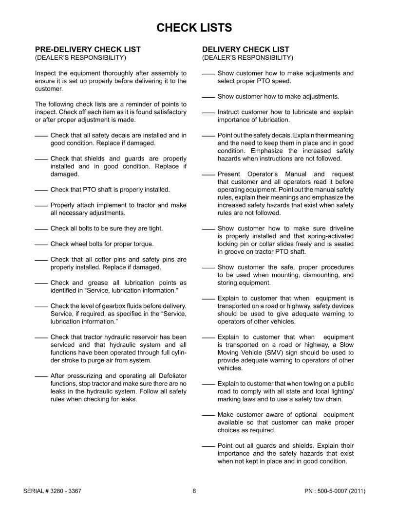
PRE-DELIVERY CHECK LIST(DEALER’S RESPONSIBILITY)
Inspect the equipment thoroughly after assembly to ensure it is set up properly before delivering it to the customer.
The following check lists are a reminder of points to inspect. Check off each item as it is found satisfactory or after proper adjustment is made.
ѩ Check that all safety decals are installed and in good condition. Replace if damaged.
ѩ Check that shields and guards are properly installed and in good condition. Replace if damaged.
ѩ Check that PTO shaft is properly installed.
ѩ Properly attach implement to tractor and make all necessary adjustments.
ѩ Check all bolts to be sure they are tight.
ѩ Check wheel bolts for proper torque.
ѩ Check that all cotter pins and safety pins are properly installed. Replace if damaged.
ѩ Check and grease all lubrication points as identified in “Service, lubrication information.”
ѩ Check the level of gearbox fluids before delivery. Service, if required, as specified in the “Service, lubrication information.”
ѩ Check that tractor hydraulic reservoir has been serviced and that hydraulic system and all functions have been operated through full cylin-der stroke to purge air from system.
ѩ After pressurizing and operating all Defoliator functions, stop tractor and make sure there are no leaks in the hydraulic system. Follow all safety rules when checking for leaks.
DELIVERY CHECK LIST(DEALER’S RESPONSIBILITY)
ѩ Show customer how to make adjustments and select proper PTO speed.
ѩ Show customer how to make adjustments.
ѩ Instruct customer how to lubricate and explain importance of lubrication.
ѩ Point out the safety decals. Explain their meaning and the need to keep them in place and in good condition. Emphasize the increased safety hazards when instructions are not followed.
ѩ Present Operator’s Manual and request that customer and all operators read it before operating equipment. Point out the manual safety rules, explain their meanings and emphasize the in creased safety hazards that exist when safety rules are not followed.
ѩ Show customer how to make sure driveline is properly installed and that spring-activated locking pin or collar slides freely and is seated in groove on tractor PTO shaft.
ѩ Show customer the safe, proper procedures to be used when mounting, dismounting, and storing equipment.
ѩ Explain to customer that when equipment is transported on a road or highway, safety devices should be used to give adequate warning to operators of other vehicles.
ѩ Explain to customer that when equipment is transported on a road or highway, a Slow Moving Vehicle (SMV) sign should be used to provide adequate warning to operators of other vehicles.
ѩ Explain to customer that when towing on a public road to comply with all state and local lighting/ marking laws and to use a safety tow chain.
ѩ Make customer aware of optional equipment available so that customer can make proper choices as required.
ѩ Point out all guards and shields. Explain their importance and the safety hazards that exist when not kept in place and in good condition.
CHECK LISTS

9PN : 500-5-0007 (2011) SERIAL # 3280 - 3367
DATE OPERATOR’S NAME OPERATOR’S SIGNATURE
OPERATOR SIGN-OFF RECORD
Safety is a primary concern in the design and manufacture of our products. Unfortunately, our efforts to provide safe equipment can be wiped out by an operator’s single careless act.In addition to the design and configuration of equipment, hazard control and accident preven tion are dependent upon the awareness, concern, judgement, and proper training of personnel involved in the operation, transport, maintenance and storage of equipment.It has been said “The best safety device is an informed, careful operator.” We ask you to be that kind of operator.
Occupational Safety and Health Administration (OSHA).
Anyone who will be operating and/or maintaining the Folding Defoliator must read and clearly understand all Safety, Operating, and Service & Maintenance information presented in this manual.
Do not operate or allow anyone else to operate this equipment until this information has been reviewed. Review this information annually, before the season start-up. Make periodic reviews of the Safety and Operation sections a standard practice for those using any of your equipment.
Use the following Operator Sign-off Record to verify that each operator has read and understood the information in this manual and has been instructed in the safe operation of the defoliator.
Alloway Equipment Company follows the general safety standards specified by the American Society of Agricultural Engineers (ASAE) and the

PN : 500-5-0007 (2011)10SERIAL # 3280 - 3367(Safety Decals continued on next page)
SAFETY & INSTRUCTIONAL DECALSATTENTION! BECOME ALERT! YOUR SAFETY IS INVOLVED!
Replace Immediately If Damaged!
1. 700-3-0519 PTO Speed Warning
3. 506-3-0194 Shield Missing Warning
2. 506-3-0193 Shield Missing Warning

11PN : 500-5-0007 (2011) SERIAL # 3280 - 3367
SAFETY & INSTRUCTIONAL DECALSATTENTION! BECOME ALERT! YOUR SAFETY IS INVOLVED!
Replace Immediately If Damaged!
5. 506-3-0195 Hydraulic Pressure Warning
6. 506-3-0192 Manual Container Warning
11. 903-17456 Driveline Safety Sign
9. 506-3-0196 Rotating Driveline Warning
13. 200-3-1366 Serial Number Tag
7. 700-3-0493 Read Manual Warning

PN : 500-5-0007 (2011)12SERIAL # 3280 - 3367
SAFETY & INSTRUCTIONAL DECALSATTENTION! BECOME ALERT! YOUR SAFETY IS INVOLVED!
Replace Immediately If Damaged!
8. 700-3-0495 Rotating Drive Hazard
14. 500-3-1687 Electrocution Hazard
12. 500-3-1688 Raised Equipment Warning
20. 500-3-1689 Rotor Damage Warning
21. 500-3-1696 SMV Sign

13PN : 500-5-0007 (2011) SERIAL # 3280 - 3367
SAFETY & INSTRUCTIONAL DECALSATTENTION! BECOME ALERT! YOUR SAFETY IS INVOLVED!
Replace Immediately If Damaged!
15. 500-3-1690 Stand/Walk on Defoliator Warning
16. 500-3-1691 Raised Wing Hazard
18. 500-3-1693 Front Transport Lock Warning
19. 500-3-1694 Rear Transport Lock Warning

PN : 500-5-0007 (2011)14SERIAL # 3280 - 3367

15PN : 500-5-0007 (2011) SERIAL # 3280 - 3367
OPERATION
Safety is a primary concern in the design and manufacture of our products. Unfortunately, our efforts to provide safe equipment can be wiped out by an operator’s single careless act.
In addition to the design and configuration of equipment, hazard control and accident prevention are dependent upon the awareness, concern, judgment, and proper training of personnel involved in the operation, transport, maintenance and storage of equipment.
It has been said “The best safety device is an informed, careful operator.” We ask you to be that kind of operator.
WARNING
� Operators must be instructed in and be capable of the safe operation of the equipment, its attachments and all con trols. Do not allow anyone to operate this equipment without proper instructions.
� Never allow children or untrained per sons to operate equipment.
CAUTION
� If you do not understand any part of this manual and need assistance, see your dealer.
� Always wear relatively tight and belted clothing to avoid entanglement in moving parts. Wear sturdy, rough-soled work shoes and protective equipment for eyes, hair, hands, hearing and head.
WARNING
� Make sure spring-activated locking pin or collar slides freely and is seated firmly in tractor PTO spline groove.
� Before starting tractor, check all equipment driveline guards for damage and make sure they rotate freely on all drivelines. Replace any damaged guards. If guards do not rotate freely on drive-lines, repair and replace bearings before operating.
� A minimum 20% of tractor and equip ment weight must be on tractor front wheels with attachments in transport position. Without this weight, tractor could tip over causing personal injury or death. The weight may be attained with a loader, front wheel weights, ballast in tires or front tractor weights. Weigh the tractor and equipment. Do not estimate.
WARNING
� Make sure all safety decals are installed. Replace if damaged. (See Safety Decals section for location.)
� Make sure shields and guards are properly installed and in good condition. Replace if damaged.
� Do not allow bystanders in the area when operating, attaching, removing, as sembling, or servicing equipment.
� Never walk, stand or place yourself or others under a raised wing or in the path of a lowering wing. Hydraulic system leak down, hydraulic system failures, mechani cal failures or movement of control levers can cause wings to drop unexpectedly and cause severe injury or death.
� Keep bystanders away from equip ment.
� Never go underneath equipment low-ered to the ground or raised, unless it is properly blocked and secured. Never place any part of the body underneath equipment or between moveable parts even when the engine has been turned off. Hydraulic sys tem leak down, hydraulic system failures, mechanical failures or movement of control levers can cause equipment to drop or ro tate unexpectedly and cause severe injury or death. Follow Operator’s Manual instruc tions for working underneath and blocking requirements, or have work done by a quali fied dealer.
� Keep hands, feet, hair and clothing away from equipment while engine is running. Stay clear of all moving parts.
� Never allow riders on power unit or attachment.

PN : 500-5-0007 (2011)16SERIAL # 3280 - 3367
Operation Continued
Figure 1. Principal Components
PRINCIPAL COMPONENTSThe Alloway Folding Defoliator is built as three major components.
a) Right Wing Assemblyb) Left Wing Assemblyc) Center Frame
The center frame is supported by hydraulically adjustable wheel struts and the hydraulically adjustable hitch. The main driveline and two gearboxes are mounted to the center frame.
� Power unit must be equipped with ROPS or ROPS CAB and seat belt. Keep seat belt securely fastened. Falling off power unit can result in death from being run over or crushed. Keep foldable ROPS systems in “locked up” position at all times.
CAUTION
Each wing assembly holds three flail rotor assem blies, their drive components, and a manually adjustable wing gauge wheel.
Optional scalper attachments can be mounted direct ly to each wing assembly.
Optional rear wheel steering struts are available.
� Operate only in daylight or good artifi cial light.
� Always comply with all state and local lighting and marking requirements.
� Avoid contact with electrical wires.

17PN : 500-5-0007 (2011) SERIAL # 3280 - 3367
PRE-OPERATION CHECK LIST(OWNER’S RESPONSIBILITY)
IMPORTANT � This Pre-Operation Check List is provided
for the operator. It is important to follow for both personal safety and maintenance of the Folding Defoliator.
To assure safe and efficient operation, it is essential that each machine operator read and understand the operating procedures and related safety require ments outlined in this manual.
Complete the Pre-Operation Check List after the first hour of field operation and before each shift thereafter.
ѩ Show customer how to make adjustments.
ѩ Keep Operator’s Manual in storage tube for ready reference and use.
ѩ Review and follow all safety rules and safety decal instructions on pages 5 through 12.
ѩ Check that all safety decals are installed and in good condition. Replace if damaged.
ѩ Check that all shields and guards are properly installed and in good condition. Replace if damaged.
ѩ Check that all hardware and cotter pins are properly installed and secured.
ѩ Check the condition of all flails and check that they swing freely. Replace any damaged or broken flails.
ѩ Check the condition of the scalpers. Adjust or repair as required.
ѩ Check tire pressures. Service as necessary.
ѩ Check that equipment is properly and securely attached to tractor.
Operation Continued
ѩ Make sure driveline spring-activated locking collar slides freely and is seated firmly in tractor PTO spline groove.
ѩ Before starting tractor, check all equipment driveline guards for damage and make sure they rotate freely on all drivelines. Replace any damaged guards. If guards do not rotate freely on drivelines, repair and replace bearings before operating.
ѩ Do not allow riders.
ѩ Check and keep all bystanders away from equipment working area.
ѩ Check the condition of all drive belts. Tension or align as required. Replace any that are frayed or broken.
ѩ Check all lubrication points and grease as instructed in “Service, lubrication information” Make sure the PTO slip joint is lubricated and that the gearbox fluid levels are correct.
ѩ Set tractor PTO at correct rpm for your equipment.
ѩ Check that all hydraulic hoses and fittings are in good condition and not leaking before starting tractor. Check that hoses are not twisted, bent sharply, kinked, frayed or pulled tight. Replace any damaged hoses immediately.
ѩ Raise and lower equipment to make sure air is purged from hydraulic cylinders and hoses.
ѩ Make sure tractor 3-point lift links do not interfere with hydraulic hoses or driveline throughout full turning range.
ѩ Make sure tractor ROPS or ROPS CAB and seat belt are in good condition. Keep seat belt securely fastened during operation to prevent falling off.
ѩ Before starting engine, operator must be in tractor seat with seat belt fastened. Place transmission in neutral or park, engage brake and disengage tractor PTO.
ѩ Check that rubber flaps are in good condition, pivot freely, and hang without gaps.

PN : 500-5-0007 (2011)18SERIAL # 3280 - 3367
Operation Continued
EQUIPMENT MATCHINGUse only a tractor with adequate power and weight to operate this Defoliator. The following specifications are guidelines for a proper match.
PTO
Tractor must be equipped with a 1000 RPM PTO. The Defoliator driveline can be ordered with a tractor yoke that matches a 1-3/8” 21-spline shaft or a 1-3/4” 20-spline shaft. Carefully measure PTO driveline in operating positions to ensure that there is proper engagement between male and female shaft to prevent the driveline from coming apart or bottoming out. Standard PTO driveline must not be shorter than 53.75” or longer than 82.88” in any position during operation, as shown in Figure 2.
WARNING
� Connect PTO driveline directly to trac tor PTO shaft. Never use adapter sleeves or adapter shafts. Adapters can cause driveline failures due to incorrect spline or incorrect operating length and result in personal injury or death.
Figure 2a. PTO Driveline Operating Length
BREAK-IN OF THE FOLDING DEFOLIATOR
The following should be observed when operating the unit for the first time:
1. Attach PTO shaft. Remove grease zerks to gain access to the set screws for tightening on unit.
After operating for 1/2 hour or after completing five acres
2. Check all nuts, bolts, and other fasteners. Tighten to specifications given in the Bolt Torque Chart, page 66.
3. Check and re-torque on flail mounting bracket fasteners
4. Tighten wheel bolts to specifications given in the Bolt Torque Chart, page 66.
5. Check that the flails are in good condition and swing freely.
6. Check oil level in the gearbox. Add oil as required.
7. Check that the PTO driveline shield turns freely.
8. Lubricate all grease points.
After operating for 5 hours
9. Repeat Steps 1 through 6 above.
10. Check the tension of the drive belts. Refer to the Service and Maintenance section for the procedure. Adjust as required.
After operating for 10 hours
11. Repeat steps 1 through 6.
12. Check tension of drive belts. Adjust as required.
After operating for 15, and 20 hours
13. Check tension of drive belts. Adjust as required.
19PN : 500-5-0007 (2011) SERIAL # 3280 - 3367
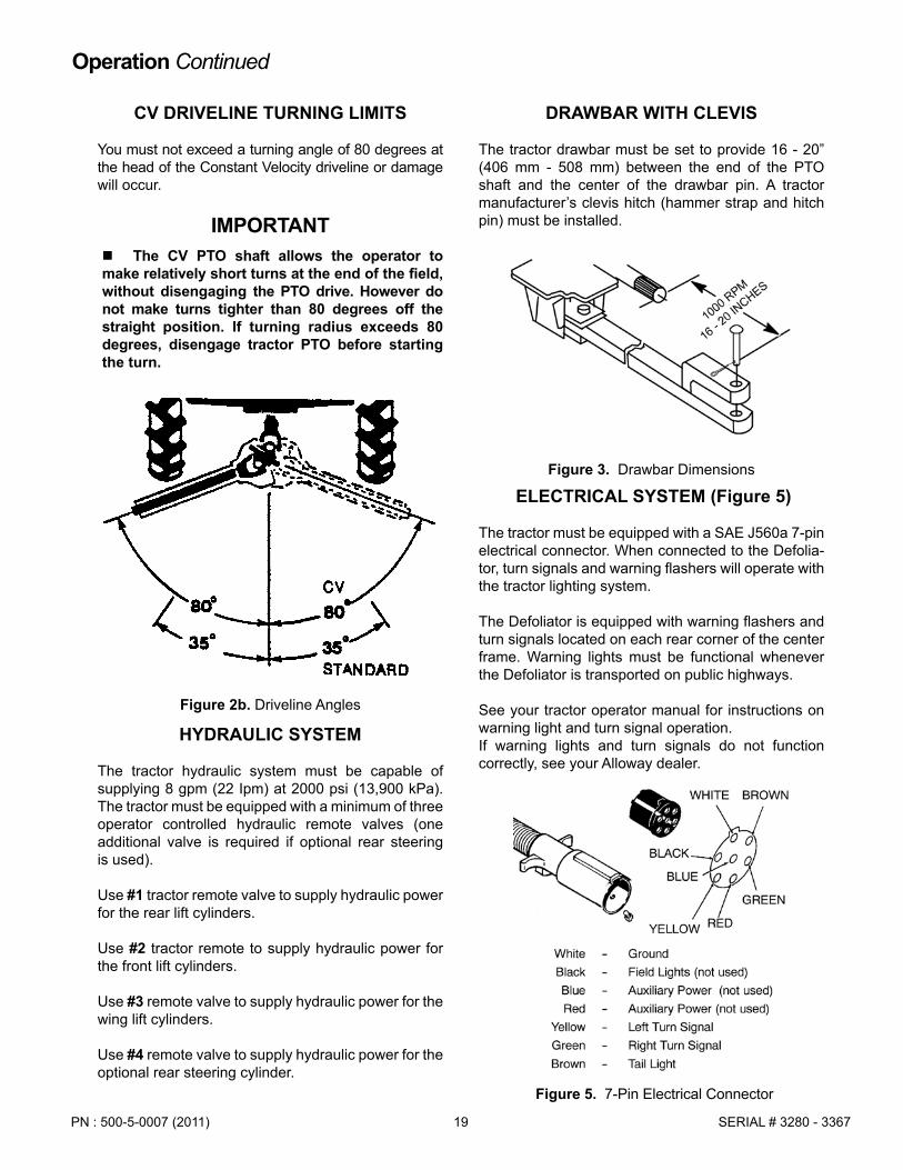
CV DRIVELINE TURNING LIMITS
You must not exceed a turning angle of 80 degrees at the head of the Constant Velocity driveline or damage will occur.
IMPORTANT � The CV PTO shaft allows the operator to
make relatively short turns at the end of the field, without disengaging the PTO drive. However do not make turns tighter than 80 degrees off the straight position. If turning radius exceeds 80 degrees, disengage tractor PTO before starting the turn.
HYDRAULIC SYSTEM
The tractor hydraulic system must be capable of supplying 8 gpm (22 Ipm) at 2000 psi (13,900 kPa). The tractor must be equipped with a minimum of three operator controlled hydraulic remote valves (one additional valve is required if optional rear steering is used).
Use #1 tractor remote valve to supply hydraulic power for the rear lift cylinders.
Use #2 tractor remote to supply hydraulic power for the front lift cylinders.
Use #3 remote valve to supply hydraulic power for the wing lift cylinders.
Use #4 remote valve to supply hydraulic power for the optional rear steering cylinder.
DRAWBAR WITH CLEVIS
The tractor drawbar must be set to provide 16 - 20” (406 mm - 508 mm) between the end of the PTO shaft and the center of the drawbar pin. A tractor manufacturer’s clevis hitch (hammer strap and hitch pin) must be installed.
Figure 3. Drawbar Dimensions
Operation Continued
ELECTRICAL SYSTEM (Figure 5)
The tractor must be equipped with a SAE J560a 7-pin electrical connector. When connected to the Defolia- tor, turn signals and warning flashers will operate with the tractor lighting system.
The Defoliator is equipped with warning flashers and turn signals located on each rear corner of the center frame. Warning lights must be functional whenever the Defoliator is transported on public highways.
See your tractor operator manual for instructions on warning light and turn signal operation.If warning lights and turn signals do not function correctly, see your Alloway dealer.
Figure 5. 7-Pin Electrical Connector
Figure 2b. Driveline Angles

PN : 500-5-0007 (2011)20SERIAL # 3280 - 3367
Operation Continued
TRACTOR BALLAST
The tractor should be equipped with manufacturer’s maximum allowable front end ballast for operational and transport stability.
PROPERLY MOUNT AND DISMOUNT TRACTOR
Proper safety procedures should be followed when mounting tractor. The operator should be in the tractor seat with the seat belt securely fastened and any foldable ROPS system should be in the “locked-up” position before starting the engine or operating any controls.
Whenever the operator is required to leave the tractor seat, follow proper safety procedures. The “proper dismounting procedure” is to stop the engine, set brakes, remove the ignition key, and wait for all moving parts to stop before removing seat belt to dismount. After dismounting the tractor, secure wheels with chocks.
ATTACHING DEFOLIATOR TO TRACTOR
Note: The following procedure presumes that the Defoliater is in “STORED POSITION” as described on page 23, with rear wheel/lift cylinder locks installed.
Make sure there are no bystanders between tractor and Defoliator or in the area.
Carefully back up until the tractor drawbar aligns with the Defoliator hitch.
Stop engine, set parking brake, wait for all moving parts to stop, and remove ignition key before dismounting.
Clean the hydraulic couplers and fittings to avoid oil contamination.
Connect the hydraulic hoses which control the front hitch/lift cylinders to remote valve #2 hydraulic couplers on the tractor. Connect these hoses so that moving the operator control lever forward lowers the Defoliator (raises the hitch tongue) and moving the operator control lever rearward raises the Defoliator (lowers the hitch tongue).
From the tractor seat, hydraulically position the height of Defoliator hitch and back up the tractor to allow the tractor clevis to align with the Defoliator hitch.
Stop engine, set parking brake, wait for all moving parts to stop, place all controls in neutral, and remove key before dismounting the tractor.
Install tractor manufacturer’s clevis hitch pin and secure with tractor manufacturer’s lock mechanism.
Attach the safety chain to the drawbar support of the tractor.
Insert the 7-pin male Defoliator electrical cable into the tractor female connector. Route electrical wires to prevent chafing, abrasion, or contact with rotating components.
Connect hydraulic hoses to tractor hydraulic couplers as shown in Figure 6.
Hydraulically raise the Defoliator, stop engine, set park brake, and wait for all moving parts to stop, and remove ignition key before dismounting.
Install cylinder locks on front hitch/lift cylinders.
5
4
3
2
1
6
7 7
1. Hydraulic valve #1 (Rear Wheel/lift cylinders)2. Hydraulic valve #2 (Front hitch/lift cylinders)3. Hydraulic valve #3 (Wing lift cylinders)4. Hydraulic valve #4 (Rear Steer Override)5. Hydraulic valve #5 (Rear Steer Self-Centering System
if Power Beyond is not available)6. Power Beyond Pressure (Rear Steer Self-Centering System)7. Power Beyond Return (Rear Steer Self-Centering System)
Figure 6. Tractor Connection (Typical)

21PN : 500-5-0007 (2011) SERIAL # 3280 - 3367
Figure 7. Front Hitch/Lift Cylinder Locks (Installed)
Raise parking stands and secure in raised position, Figure 8. Make sure all cylinder locks are in place.
Check that all PTO driveline guards are in place and that driveshaft telescopes correctly. Attach PTO driveshaft to tractor and make sure locking pin or collar is fully engaged.
Verify that all tractor hydraulic control lever move-ments are correct before operating or transporting the Defoliator.
Figure 8. Parking Stand in Raised Position
VERIFICATION OF CONTROL MOVEMENTS
Comply with all Safety Rules and start the tractor. Check that all tractor hydraulic control lever move-ments operate the Defoliator correctly as shown in Figure 9 through Figure 12.
Defoliater movements must be correct before proceeding with field operation. If movements are not correct, recheck all hydraulic coupler connections.
Figure 9. Rear Wheel/Lift Cylinders
Figure 10. Front Hitch/Lift Cylinders
Operation Continued
Figure 11. Wing Raise/Lower Cylinders
Figure 12. Rear Steering Cylinders (Optional)
PN : 500-5-0007 (2011)22SERIAL # 3280 - 3367
Operation Continued
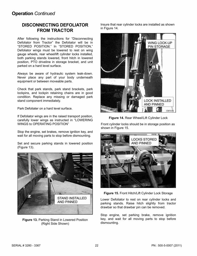
Front cylinder locks should be in storage position as shown in Figure 15.
Figure 15. Front Hitch/Lift Cylinder Lock Storage
Lower Defoliator to rest on rear cylinder locks and parking stands. Raise hitch slightly from tractor drawbar so that drawbar pin can be removed.
Stop engine, set parking brake, remove ignition key, and wait for all moving parts to stop before dismounting.
DISCONNECTING DEFOLIATOR FROM TRACTOR
After following the instructions for “Disconnecting Defoliator from Tractor” the Defoliator will be in “STORED POSITION.” In “STORED POSITION,” Defoliator wings must be lowered to rest on wing gauge wheels, rear wheel/lift cylinder locks installed, both parking stands lowered, front hitch in lowered position, PTO driveline in storage bracket, and unit parked on a hard level surface.
Always be aware of hydraulic system leak-down. Never place any part of your body underneath equipment or between moveable parts.
Check that park stands, park stand brackets, park lockpins, and lockpin retaining chains are in good condition. Replace any missing or damaged park stand component immediately.
Park Defoliater on a hard level surface.
If Defoliator wings are in the raised transport position, carefully lower wings as instructed in “LOWERING WINGS to OPERATING POSITION”
Stop the engine, set brakes, remove ignition key, and wait for all moving parts to stop before dismounting.
Set and secure parking stands in lowered position (Figure 13).
Figure 13. Parking Stand in Lowered Position (Right Side Shown)
Insure that rear cylinder locks are installed as shown in Figure 14.
Figure 14. Rear Wheel/Lift Cylinder Lock

23PN : 500-5-0007 (2011) SERIAL # 3280 - 3367
Figure 16. PTO Rest
RAISING WINGS TO TRANSPORT POSITION
WARNING
� Never walk, stand or place yourself or others under a raised wing or in the path of a lowering wing. Hydraulic system leak down, hydraulic system failures, mechani cal failures or movement of control levers can cause wings to drop unexpectedly and cause severe injury or death.
CAUTION
� Before raising or lowering wings, front hitch/lift and rear wheel/lift cylinders must be fully extended and all four cylinder locks installed. This prevents rotor and bearing support damage that can result from ground contact.
When raising wings to transport position, the Defolia-tor must be securely attached to the tractor with front hitch/lift and rear wheel/lift cylinder locks installed as shown in Figure 7 and Figure 14.
Make sure that wing lock-up pins are in their storage positions as shown in Figure 14.
Fully raise front and rear of Defoliator and move tractor control lever #3 to raise wings to transport position.
Stop engine, set parking brake, wait for all moving parts to stop, and remove ignition key before dismounting.
Install wing lock-up pins as shown in Figure 17.
Check that the hitch is securely attached to the tractor drawbar and the safety chain is properly fastened.
Lower hydraulic cylinders to rest on cylinder locks.
Operation Continued
Figure 17. Wing Lock-Up Pin Installation
Remove drawbar pin.
Disconnect PTO from tractor shaft and place PTO on PTO storage rest, Figure 16. Carefully drive tractor ahead far enough to disengage hitch from tractor drawbar.
Disconnect hydraulic lines and electrical connector.

PN : 500-5-0007 (2011)24SERIAL # 3280 - 3367
Operation Continued
Figure 20. Rear Wheel/Lift Cylinder Lock Storage
LOWERING WINGS TO OPERATING POSITION
WARNING
� Never walk, stand or place yourself or others under a raised wing or in the path of a lowering wing. Hydraulic system leak down, hydraulic system failures, mechani cal failures or movement of control levers can cause wings to drop unexpectedly and cause severe injury or death.
CAUTION
� Before raising or lowering wings, front hitch/lift and rear wheel/lift cylinders must be fully extended and all four cylinder locks installed. This prevents rotor and bearing support damage that can result from ground contact.
When lowering wings to operating position, the Defoliator must be properly attached to the tractor on level ground, with front hitch/lift and rear wheel/lift cylinder locks installed and pinned as shown in Figure 7 and Figure 14.
Use tractor hydraulic lever #3 to relieve pressure on wing lock pins.
Stop engine, set parking brake, wait for all moving parts to stop, and remove ignition key before dismounting.
Remove wing lock-up pins and place in storage position as shown in Figure 19.
Figure 19. Wing Lock-Up Pin (Installed)
Figure 18. Inside Flail Tube Brackets
Lower the wings to rest the wing gauge wheels on the ground. Retract wing cylinders completely to allow wings to follow ground contour during operation.
Note: Pull ahead several feet to help align wing wheels before making final field adjustments.

25PN : 500-5-0007 (2011) SERIAL # 3280 - 3367
FIELD OPERATIONThe Alloway Defoliator will give best performance if it is properly set to work in existing conditions.
IMPORTANT
� Field conditions may require addition al fine adjustment since tractor tracks are usually lower from cultivating and other previous field operations.
Machine setting may require adjustment within or between fields as conditions change. Changes in soil moisture, soil density or even beet varieties may affect performance.
Defoliator must be adjusted so that wheels are centered between rows and rubber flail assemblies are centered over beet rows. All flail tips should be about 1/2” above the ground.
Before entering the field initially, the machine should be unfolded on firm and level ground.
LEVELING THE DEFOLIATOR
Place Defoliator wings in operating position.
Remove front hitch/lift and rear wheel/lift cylinder locks.
Lower rear of machine until the rubber flail tips contact the beets 1/2” below the crown.
Lower the front of the machine until the Defoliator wings are parallel to the ground. Adjust front hitch/lift and rear wheel/lift cylinder stop collars (Figure 21) to establish the operating position of the center frame. Fine adjustment may be required to match field conditions.
Adjust wing gauge wheels so that wings are level across the beet tops.
Adjust the ratchet jacks on each gauge wheel strut to level the wings and establish flail cutting height.
On machines equipped with steel flail front rotor, the steel flail tips are 4” shorter than the rubber flail tips. Steel flails should remove only greens and not damage beet crowns, while rubber flails remove the residual foliage and deposit leaves between the beet rows.
Figure 21. Rear Wheel/Lift Cylinder Stop Collars
Figure 22. Leveling Defoliator
Figure 23. Gauge Wheel Ratchet Jack
Operation Continued
Machines may be equipped with rubber flails on all rotors. The load of leaf removal should be split between the #1 and #2 rotor. For that reason fewer flails are used on the #1 rotor.

PN : 500-5-0007 (2011)26SERIAL # 3280 - 3367
ENTERING THE FIELD
Pull into the field with the tractor centered on the first set of rows.
Lower the machine front and rear to the pre-set position. Scalpers will automatically lower after the rear depth control cylinders bottom out.
STARTING DEFOLIATOR
With the tractor engine at idle, slowly engage the PTO and choose your forward speed setting. Recom-mended speed in average conditions is 2 to 3 mph.
Increase engine speed to PTO speed.
Release clutch and move tractor forward following the beet rows.
If the performance of the Defoliator is not satisfactory, stop the unit and make any necessary adjustments.
STOPPING DEFOLIATOR
Reduce engine speed and depress clutch. Take tractor out of gear. After engine has slowed to idle, disengage PTO.
IMPORTANT
� Never disengage PTO at high RPM because the inertia of the turning rotors in the Defoliator can damage the tractor PTO brake.
Stop engine, set parking brake, wait for all moving parts to stop, and remove ignition key before dismounting.
Check behind the Defoliator to observe performance.
Further fine-adjustment on wing gauge wheels and/or center carrier may be needed for satisfactory perfor-mance.
FIELD PERFORMANCE
Many factors will influence the performance of the Defoliator:
• Bulk of leaf canopy • Moisture content of foliage Frozen leaves • Beet varieties• Beet stand • Cultivating job • Forward speed • Soil moisture content Height of beds
The operator will have to adjust the machine accordingly.
In soft or wet conditions, the tires will sink into the soil and the machine should be raised to maintain the flail contact point 1/2” below the beet crown.
In conditions where beets extend above the ground and are easily knocked over, adjust flails to contact beet at or just below the crown.
Do not allow the flails to contact the ground. Dirt, stones or other material can be thrown from under the machine.
Running the flails too low causes high flail wear and breakage, higher fuel consumption, and more build up inside the machine. Tall beets may be kicked between rows.
Operation Continued

27PN : 500-5-0007 (2011) SERIAL # 3280 - 3367
Figure 25. Scalper Adjustment
REAR STEERING (Optional)
Figure 24. Rear Steering
Rear wheel steering struts are used when additional maneuverability is required. Tractor must be equipped with a fourth hydraulic control lever if rear steering is to be used.
To operate the rear steering, connect hydraulic hoses so that moving the #4 control lever forward steers the Defoliator to the right and moving the #4 control lever rearward moves the Defoliator to the left.
Use the rear steering system to adjust the offset of the Defoliator for field operation. Ensure that rear steering is “centered” for transport and is tracking directly behind the tractor.
SCALPERS (Optional)
WARNING
� Do not handle blades with bare hands. Careless or improper handling may result in serious injury.
The scalper option available from Alloway is a non-driven, mechanically rotating disc. Scalper lift cylinders operate in parallel with the rear wheel lift cylinders. When raising the rear of the Defoliator, scalper attachments will raise first. When lowering the rear of the Defoliator, scalper attachments will lower last.
IMPORTANT � Always raise scalpers before backing
up. Scalpers must be fully raised before folding wings.
The disc will rotate to either side and a sharp cutting edge is exposed to do the scalping job. When properly adjusted, it will stay free of debris and consistently cut the required amount of the beet crown.
Uneven beet stands and double beets will cause less than perfect performance. Adjustments should be made to regulate the thickness of the slice to be removed.
Forward speed changes will influence the perfor-mance.
In any working position, the disc forward edge of the disc should always be a few degrees lower than the rear edge.
Scalpers are factory pre-set, but need fine adjustment for individual conditions.
CAUTION
� Never work on scalper attachment in the raised position. Lower scalpers to the ground and service each unit individually.
Operation Continued

PN : 500-5-0007 (2011)28SERIAL # 3280 - 3367
DEFOLIATOR STORED POSITIONLower wings to operating position and disconnect Defoliator from tractor as described in “Disconnecting Defoliator from Tractor.” Defoliater should be in “STORED POSITION” and be supported by park stands, rear wheel/lift cylinder locks, and wing gauge wheels.
Gauge wheel screw jacks may be adjusted to support wings in a level position.
Store Defoliator in an area away from children and bystanders.
Do not allow children to play on or around the stored unit.
Store in a dry, level area.
Operation Continued
Figure 27. Parking Stand
Loosen shoe adjustment bolts and adjust scalper shoe. The trailing surface of the shoe should be nearly horizontal.
Loosen disc adjustment bolts to adjust disc operating pitch. Adjust pitch of scalper disk to slice beets as required.
When adjustments are complete, tighten bolts to specifications in torque chart.
Figure 26. Scalper Attachment
TRANSPORTING THE DEFOLIATOR
When transporting on public roads, wings must be raised to transport position. Follow instructions in “Raising Wings to Transport Position.”
Make sure reflector, lights and the SMV sign are clean and clearly visible to other traffic.
Do not allow riders.Use hazard flashers on the tractor when transporting.
Never exceed safe travel speed. Slow down when making turns and traveling on rough roads or shoulders.
Make sure to use a tractor of sufficient size and with enough front end ballast to assure safe steering.
Lock foot brake pedals for even application during road travel.

29PN : 500-5-0007 (2011) SERIAL # 3280 - 3367
OWNER SERVICE
Safety is a primary concern in the design and manufacture of our products. Unfortunately, our efforts to provide safe equipment can be wiped out by an operator’s single careless act.
In addition to the design and configuration of equipment, hazard control and accident prevention are dependent upon the awareness, concern, judgement, and propertraining of personnel involved in the operation, transport, maintenance and storage of equipment.
It has been said “The best safety device is an informed, careful operator.” We ask you to be that kind of operator.
The information in this section is written for the operator who possesses basic mechanical skills. Should you need help, your dealer has trained service technicians available. For your protection, read and follow all safety information in this manual.
WARNING
� Service and maintenance work not covered in OWNER SERVICE must be done by a qualified dealership. Special skills, tools and safety procedures may be required. Failure to follow these instruc tions can result in serious injury or death.
� Before working underneath a raised implement, read and follow all operator’s manual instructions and safety rules. Im plement must be attached to tractor, lift cylinder locks must be installed, and lift cylinders lowered against locks. Hydrau lic system leak down, hydraulic system failures, or movement of control levers can cause equipment to drop unexpected ly and cause severe injury or death.
� Never perform service or maintenance with engine running.
� Do not disconnect hydraulic lines until engine is stopped, tractor is properly se cured, equipment and all components are lowered to the ground, and system pres sure is released by operating all valve control levers.
� Keep all persons away from operator control area while performing adjust ments, service or maintenance.
� Never go underneath equipment low ered to the ground or raised, unless it is properly blocked and secured. Never place any part of the body underneath equipment or between moveable parts even when the engine has been turned off. Hydraulic sys tem leak down, hydraulic system failures, mechanical failures or movement of control levers can cause equipment to drop or rotate unexpectedly and cause severe injury or death. Follow Operator’s Manual instruc tions for working underneath and blocking requirements, or have work done by a quali fied dealer.
CAUTION
� Always wear relatively tight and belted clothing to avoid entanglement in moving parts. Wear sturdy, rough-soled work shoes and protective equipment for eyes, hair, hands, hearing and head.
BLOCKING METHODDo not work underneath the Defoliator unless it is properly attached to the tractor and blocked securely. When properly attached, the unit will be anchored to minimize front-to-rear movement. Do not work on Defoliator with wings in any intermediate position.
Figure 28 Jackstand Locations
For any service work which requires working under-neath the Defoliator, the following blocking instructions must be followed.
The Defoliator must be properly attached to a tractor located on a hard level surface.

PN : 500-5-0007 (2011)30SERIAL # 3280 - 3367
LUBRICATION
GEARBOX OIL
Use 80W90 gear lube. Capacity: 2 US quarts.
GREASING
Use a multi-purpose high temperature grease.
Note: Over-greasing can cause damage to bearing seals.
a. Use hand held grease gun to avoid blown seals.
b. Wipe grease fittings clean to avoid contami nation.
c. Replace or repair broken fittings immediately.d. If fittings do not take grease, remove zerk,
and clean passageway.
Figure 30. Lubrication Points
The Defoliator wings must be lowered into operating position with wing gauge wheels adjusted to support the wings during service.
Front and rear cylinder locks must be properly installed. Do not use a cylinder lock or retaining pin which is bent or damaged. Replace any damaged or lost cylinder lock components immediately.
Jackstands, with a minimum load rating of 4000 lbs each, must be placed under the wing frames at each corner of the right and left wings as shown in Figure 28. Jackstands should be adjusted so that they securely support the Defoliator during service.
Tractor park brake must be engaged, wheels chocked, and PTO shaft disconnected from the tractor.
Owner Service Continued

31PN : 500-5-0007 (2011) SERIAL # 3280 - 3367
Figure 29. Inside Rotor Bearings
Grease Intervals
10 Hours
1. Grease CV PTO portion of the driveline.
2. Grease PTO driveline with regular universals and shield zerks.
20 Hours
3. Grease all telescoping drive shafts on top of the machine including shield zerks.
4. Grease wing hinge points and all lift arm linkages.
40 Hours
5. Grease rear steering pivots (Figure 31).
6. Grease all rotor bearings (Figure 29 and Figure 30).
7. Grease all line shaft bearings.
8. Grease hitch and rear carrier hinge points.
5
5
5
Figure 31. Rear Steering Pivots
Figure 32. Gauge Wheel Jack Screws
Sealed Bearing Information (Figure 29)
Moisture and contaminants can be trapped behind the bearing seals.
Usually a single pump of a hand held grease gun every 40 hours of operation will be sufficient to force moisture out and relube the bearing. Please keep this in mind when greasing line shaft or rotor bearings on the Defoliator.
Annually
9. Change oil in gearboxes.
10. Clean gearbox breathers.
11. Repack carrier wheel bearings.
12. Inspect scalper bearings.
13. Grease gauge wheel jack screws (Figure 32).
Grease all zerks after washing and at outset or end of season to remove potential moisture from bearings.
Owner Service Continued

PN : 500-5-0007 (2011)32SERIAL # 3280 - 3367
Replacing Drive Belts (Figure 33 & Figure 34)
Stop tractor engine, put all controls in neutral, remove ignition key, and wait for all moving parts to stop before dismounting.
Open and secure lower belt housing shields.
Loosen bearing plate anchor bolts (A).
Loosen nuts on tightener rod and bring rotor shaft to the extreme loose position.
Replace belt on sheaves as shown in Figure 33 and Figure 34.
Adjust nuts on tightener rod (B) until proper tension is reached.
Retighten bearing plate (A).
Close and secure belt housing shields
Figure 34. Rotor Upper Drive Pulleys
MAINTENANCE
DRIVE BELTS
Belt Tension
Banded drive belts are used to transmit power to the rotor shafts. Improperly adjusted belts will create heat which results in poor performance and fast belt wear. It is wise to check belts every 4 to 5 hours, if they feel cool to touch, they are adjusted well. Any high heat should signal a need for adjustment.
Note: Heat buildup can also be caused by running flails too close to the ground or excessive build up inside the Defoliator.
Adjusting Belt Tension (Figure 33)
Stop tractor engine, put all controls in neutral, remove ignition key, and wait for all moving parts to stop before dismounting.
Open and secure lower belt housing shields.
Loosen bearing plate anchor bolts (A).
Adjust nuts on tightener rod (B) until proper tension is reached.
Retighten bearing plate (A).
Close and secure belt housing shields.
Figure 33. Belt Tension Adjustment - Belt Box
Owner Service Continued

33PN : 500-5-0007 (2011) SERIAL # 3280 - 3367
FLAIL REPLACEMENT
Securely block-up the Defoliator as described in “Blocking Method for Defoliator Service,” Figure 28.
WARNING
� Never walk, stand or place yourself or others under a raised wing or in the path of a lowering wing. Hydraulic system leak down, hydraulic system failures, mechani cal failures or movement of control levers can cause wings to drop unexpectedly and cause severe injury or death.
IMPORTANT � Always replace opposite pairs of
knives and mounting hardware to main tain rotor balance. Replace any broken or missing knife immediately.
L-Knife/Cup
Remove bolt from flail bracket and remove flail.
Replace flail bushing and tighten bolt to specifications in Torque Chart.
Rubber Flail
Rubber flails are attached to adjustable flail heads, which are clamped to the rotor.
To replace rubber flails, remove flail pin retaining bolt and withdraw pin. Remove flail assembly as a unit. Head clamping bolts may need to be loosened to make disassembly easier.
Note location of flails, spacers and bushings. Replace any worn, damaged or missing components in their correct location. Insert flail pin through assembly and install retaining bolt. Tighten flail pin retaining bolt to specifications in Torque Chart.
Inspect flail heads to determine that they are securely clamped to rotor. If flail heads are not attached securely, tighten clamping bolts to specifications in Torque Chart.
Figure 35. Flail Assembly
Owner Service Continued

PN : 500-5-0007 (2011)34SERIAL # 3280 - 3367
TROUBLE SHOOTINGThe Alloway Folding Defoliator uses rubber or steel flails on drums to remove foliage from the tops of sugar beets. It is a simple and reliable system that requires minimal maintenance. The following table lists problems, causes, and solutions that you may
encounter. If you encounter a problem that is difficult to solve even after reading through this table, please call your local Alloway dealer. When calling, please have this manual and your unit’s serial number ready.
PROBLEM POSSIBLE CAUSE SOLUTION
Drums won’t turn
Tractor PTO defective Repair tractor PTO
Broken cross shaft or drive coupler on central hanger bearing Replace (9 or 12 row units only)
Rapid belt wear
Machine plugged Unplug machine
Pulleys out of alignment Align pulleys
Loose or overtightened belts Adjust belt tension
Overloaded/Running too low Raise unit or slow down
Flails breakingMachine too low Raise machine
Hitting rocks or other debris Clean field better before planting
Tires don’t turn Mud buildup Adjust tire pressure to 15-20 psi
Beet crown not clean
Machine too high Lower the machine
Flails broken Replace broken flails
Traveling too fast Slow down
Running slow (tractor) Increase speed to rated PTO RPM
Need a scalper Install and set scalper
Scalper bounces Increase scalper spring tension
Beets are pulled out of the ground
Machine too low Raise machine
Machine too slow Increase ground speed
Scalper pulling beets out of ground Adjust scalper
Defoliator vibrates
Driveline doesn’t telescope Remove, disassemble, and clean telescoping joint
Flail tube out of balance
Balance tube
Replace missing knives orrubber flails. Always replace in
pairs 180 degrees apart.
35PN : 500-5-0007 (2011) SERIAL # 3280 - 3367
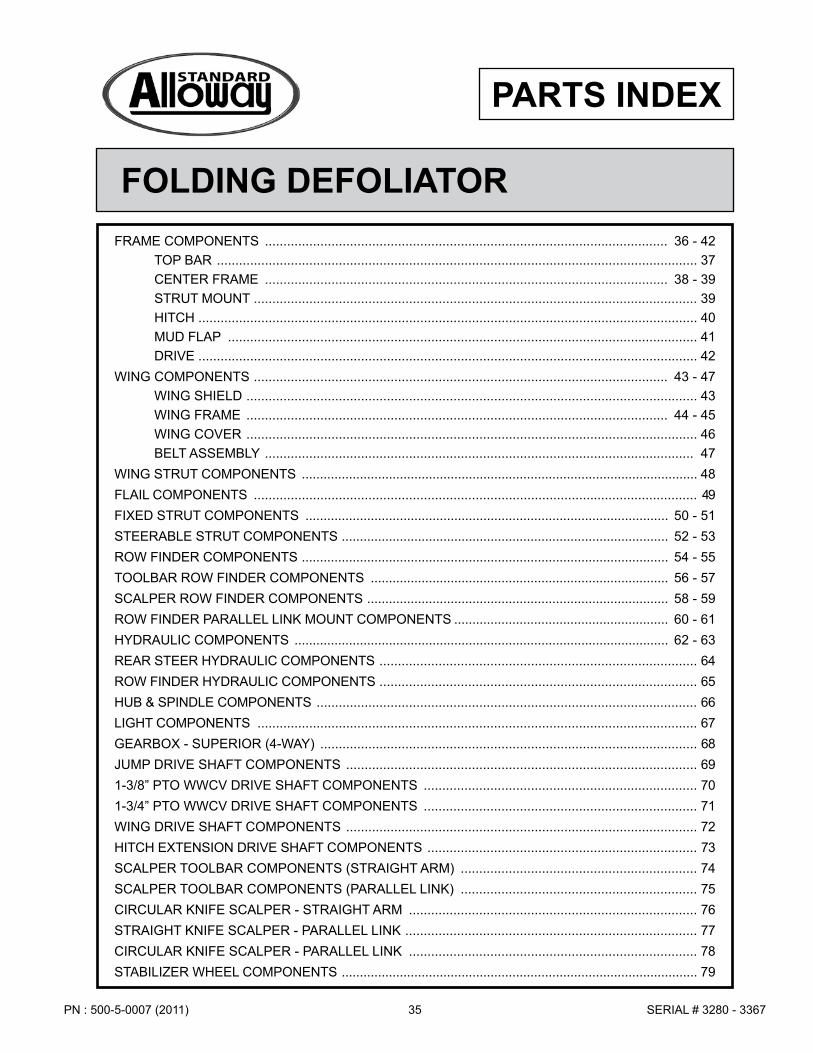
FOLDING DEFOLIATOR
PARTS INDEX
FRAME COMPONENTS ............................................................................................................. 36 - 42TOP BAR .................................................................................................................................. 37CENTER FRAME ............................................................................................................. 38 - 39STRUT MOUNT ........................................................................................................................ 39HITCH ....................................................................................................................................... 40MUD FLAP ............................................................................................................................... 41DRIVE ....................................................................................................................................... 42
WING COMPONENTS ................................................................................................................ 43 - 47WING SHIELD .......................................................................................................................... 43WING FRAME .................................................................................................................. 44 - 45WING COVER .......................................................................................................................... 46BELT ASSEMBLY .................................................................................................................... 47
WING STRUT COMPONENTS ............................................................................................................. 48FLAIL COMPONENTS ........................................................................................................................ 49FIXED STRUT COMPONENTS .................................................................................................... 50 - 51STEERABLE STRUT COMPONENTS .......................................................................................... 52 - 53ROW FINDER COMPONENTS ..................................................................................................... 54 - 55TOOLBAR ROW FINDER COMPONENTS .................................................................................. 56 - 57SCALPER ROW FINDER COMPONENTS ................................................................................... 58 - 59ROW FINDER PARALLEL LINK MOUNT COMPONENTS ........................................................... 60 - 61HYDRAULIC COMPONENTS ....................................................................................................... 62 - 63REAR STEER HYDRAULIC COMPONENTS ...................................................................................... 64ROW FINDER HYDRAULIC COMPONENTS ...................................................................................... 65HUB & SPINDLE COMPONENTS ....................................................................................................... 66LIGHT COMPONENTS ....................................................................................................................... 67GEARBOX - SUPERIOR (4-WAY) ...................................................................................................... 68JUMP DRIVE SHAFT COMPONENTS ............................................................................................... 691-3/8” PTO WWCV DRIVE SHAFT COMPONENTS .......................................................................... 701-3/4” PTO WWCV DRIVE SHAFT COMPONENTS .......................................................................... 71WING DRIVE SHAFT COMPONENTS ............................................................................................... 72HITCH EXTENSION DRIVE SHAFT COMPONENTS ......................................................................... 73 SCALPER TOOLBAR COMPONENTS (STRAIGHT ARM) ................................................................ 74 SCALPER TOOLBAR COMPONENTS (PARALLEL LINK) ................................................................ 75 CIRCULAR KNIFE SCALPER - STRAIGHT ARM .............................................................................. 76STRAIGHT KNIFE SCALPER - PARALLEL LINK ............................................................................... 77CIRCULAR KNIFE SCALPER - PARALLEL LINK .............................................................................. 78STABILIZER WHEEL COMPONENTS .................................................................................................. 79

PN : 500-5-0007 (2011)36SERIAL # 3280 - 3367
FRAME COMPONENTS - COMPLETE ASSEMBLY
ITEM NO. PAGE NUMBER DESCRIPTION
1 37 TOP BAR SECTION2 38 - 39 CENTER FRAME SECTION3 39 STRUT MOUNT SECTION4 40 HITCH SECTION5 41 MUD FLAP SECTION6 42 DRIVE SECTION

37PN : 500-5-0007 (2011) SERIAL # 3280 - 3367
FRAME COMPONENTS - TOP BAR SECTION
1
5
7
6
9
810
11
1110
8
9
12
2
1413
141312
3
ITEM NO. PART NUMBER DESCRIPTION QTY.
1 500-2-0661 TOP BAR WELD 12 905-21417 CYLINDER, 4 X 24 W/ 3/4-16 ORB PORTS 2
905-21415 SEAL KIT, 4 X 24 3 500-2-0662 LINK ARM WELD 24 500-2-0954 PIVOT TUBE WELD 2
5 500-2-0685 CHANNEL PIN WELD 26 500-3-1510 CHANNEL PIN CAP 27 900-23045 PIN, COTTER 3/16 X 2 28 500-2-0684 PIN WELD, 1-1/4 49 900-01225 BOLT, HEX HEAD 1/2 X 1-1/2, GR5 ZP 4
10 900-11013 WASHER, LOCK 1/2 411 900-06009 NUT, HEX HEAD 1/2 412 900-01515 BOLT, HEX HEAD 1 X 2-1/2, GR5 ZP 613 900-11021 WASHER, LOCK 1 614 900-06019 NUT, HEX HEAD 1 6

PN : 500-5-0007 (2011)38SERIAL # 3280 - 3367
8
7
2
34
5
3
9
6
5
1011
1213
15
1614 15
11
14
11
101112131114
1115
1415
17
1
9
3
FRAME COMPONENTS - CENTER FRAME SECTION

39PN : 500-5-0007 (2011) SERIAL # 3280 - 3367
ITEM NO. PART NUMBER DESCRIPTION QTY.
1 500-2-0664 CENTER FRAME WELDMENT 12 905-21400 CYLINDER, 3-1/2 X 8 W/ DEPTH STOP 2
905-21401 SEAL KIT, 3-1/2 X 8 905-21407 DEPTH STOP NUT - LARGE
3 120-3-0472 RETAINING CHAIN 6
4 700-2-0159 CYLINDER STOP WELD 25 901-01318 BUSHING, 2-1/4 X 2-1/2 X 2, SPLT B 26 100-3-3957 MANUAL STORAGE TUBE 17 100-3-3958 MANUAL TUBE CLAMP 18 500-2-0658 MAINFRAME STAND 2
9 900-42054 SNAP LOCK CLEVIS PIN, 5/8 X 4 410 900-06009 NUT, HEX HEAD 1/2 ZP 811 900-11013 WASHER, LOCK 1/2 ZP 2412 900-11035 WASHER, FLAT �557 X 1�368 X �086 813 500-3-1684 RUBBER HINGE 4
14 900-01221 BOLT, HEX HEAD 1/2 X 1, GR5 ZP 1615 900-01227 BOLT, HEX HEAD 1/2 X 1-3/4, GR5 ZP 816 500-3-1679 GEARBOX SHIELD RH 217 500-3-1680 GEARBOX SHIELD LH 2
FRAME COMPONENTS - CENTER FRAME SECTION
FRAME COMPONENTS - STRUT MOUNT SECTION
34
2
1
66
58
7
ITEM NO. PART NUMBER DESCRIPTION QTY.
1 500-2-0659 STRUT MOUNT WELDMENT 12 905-21400 CYLINDER, 3-1/2 X 8 W/ DEPTH STOP 2
905-21401 SEAL KIT, 3-12 X 8905-21407 DEPTH STOP NUT - LARGE
3 700-2-0159 CYLINDER STOP 2
4 120-3-0472 RETAINING CHAIN 25 500-2-0748 PIN WELDMENT 26 901-01318 BUSHING, 2-1/4 X 2-1/2 X 2, SPLT B 47 900-01221 BOLT, HEX HEAD 1/2 X 1, GR5 ZP 28 900-11013 WASHER, LOCK 1/2 ZP 2
PN : 500-5-0007 (2011)40SERIAL # 3280 - 3367
FRAME COMPONENTS - HITCH SECTION
1
27
26
252
24 235
22 21 4 20
1716
19
37
188 16
1012
10 11 13
15 149
6
ITEM NO. PART NUMBER DESCRIPTION QTY.
1 905-18411 SHAFT, PTO DRIVE 1-3/4 1905-18412 SHAFT, PTO DRIVE 1-3/8 1
2 903-18007 PTO BELL 23 500-3-2164 GUARD BRACKET 24 901-01185 BEARING 1-3/4 (107022) 2
5 500-3-2165 SHAFT, PTO TRANSFER 16 500-2-0663 HITCH WELDMENT 17 905-07123 CHAIN, SAFETY TOW (21,000 LB) 18 505-3-0831 HITCH TONGUE (CAT-3) 19 700-2-0019 PIN WELD 2
10 900-31069 HOSE CLAMP BODY11 900-31068 TOP PLATE, CLAMP BODY12 900-31071 BOLT, STACKING 5/16 UNC13 900-02356 BOLT, HEX HEAD 5/16 X 1-3/4, GR5 ZP14 900-11013 WASHER, LOCK 1/2 ZP 3
15 900-01221 BOLT, HEX HEAD 1/2 X 1, GR5 ZP 216 900-06514 NUT, TOP LOCK 1 ZP 317 900-02930 BOLT, HEX HEAD 1 X 7, GR5 ZP 218 900-01519 BOLT, HEX HEAD 1 X 3, GR5 ZP 119 900-06013 NUT, HEX HEAD 5/8 ZP 8
20 900-11015 WASHER, LOCK ZP 821 900-01345 BOLT, HEX HEAD 5/8 X 2, GR5 ZP 822 900-01105 BOLT, HEX HEAD 3/8 X 3/4, GR5 ZP 823 900-06135 NUT, LOCK, SERR FLANGE 1/4 ZP 824 900-01005 BOLT, HEX HEAD 1/2 X 3/4, GR5 ZP 8
25 900-11033 WASHER, FLAT 3/8 ZP 826 900-11011 WASHER, LOCK 3/8 ZP 827 900-06005 NUT, HEX HEAD 3/8 ZP

41PN : 500-5-0007 (2011) SERIAL # 3280 - 3367
FRAME COMPONENTS - MUD FLAP SECTION
1
2
67
8
9
3
4
79
9
75
ITEM NO. PART NUMBER DESCRIPTION QTY.
1 500-3-2211 FRONT FLAP MOUNT 12 700-3-1220 RUBBER FLAP 13 500-3-2238 DEFLECTOR SHIELD - DIVIDER 14 500-3-2237 DEFLECTOR SHIELD MOUNT 15 100-3-2582 U-BOLT 1/2 X 4 X 5�5 2
6 900-06143 NUT, SPIRALOCK FLANGE 1/2 47 900-06139 NUT, SERR FLANGE 3/8 148 900-11033 WASHER, FLAT 3/8 79 900-01109 BOLT, HEX HEAD 3/8 X 1, GR5 ZP 14

PN : 500-5-0007 (2011)42SERIAL # 3280 - 3367
FRAME COMPONENTS - DRIVE SECTION
ITEM NO. PART NUMBER DESCRIPTION QTY.
1 903-18308 HITCH EXTENSION DRIVE SHAFT 12 903-15560 GEARBOX, SUPERIOR R-600 (1:1�35 GEAR RATIO) 23 903-18055 WING DRIVE SHAFT 44 903-18198 JUMP DRIVE SHAFT 15 100-3-3333 KEY 3/8 X 3/8 X 2 12
6 905-01238 NIPPLE, 1/2 NPT X 6 (GALVANIZED) 27 905-01189 COUPLING 1/2 NPT (STAINLESS STEEL) 2
1
2
2
5
7
6
4
3
3

43PN : 500-5-0007 (2011) SERIAL # 3280 - 3367
WING SHIELD COMPONENTS
ITEM NO. PART NUMBER DESCRIPTION QTY.
1 500-3-2328 TOP DOOR 12 500-3-2327 BOTTOM DOOR 13 500-2-0955 DOOR HINGE 14 500-3-2109 SIDE SHIELD 25 500-3-2111 TOP SHIELD 1
6 500-3-2110 BOTTOM SHIELD 17 500-3-1632 BACK SHIELD 18 900-06630 CLIP-ON NUT, 1/2-13 (DOOR ONLY) 19 900-06631 CLIP-ON NUT, 1/2-13 (SHIELD ONLY) 6
500-2-1277 WING SHIELD (COMPLETE) -
4
9
7
6
9
5
8
4
2
3
1

PN : 500-5-0007 (2011)44SERIAL # 3280 - 3367
46
36
35
33
1
2
1211
3
1034
1237
938
1139
810
4234
4537
24
938
40
23
842
22
45
21
48
3439
440
24
3738
23
421722
47
21
435
3940
6
13
7
18
16
46
19
615
714
2529
3126
20
4143
2730
2832
4244
4243
WING FRAME COMPONENTS
ITEM NO. PART NUMBER DESCRIPTION QTY.
1 500-2-0674 WING WELDMENT (RH) 1500-2-0673 WING WELDMENT (LH)
2 500-3-2380 COVER SPLICE CHANNEL (BACK) 23 500-3-2379 COVER SPLICE CHANNEL (FRONT) 24 500-2-1118 SMOOTH FLAIL DRUM 1
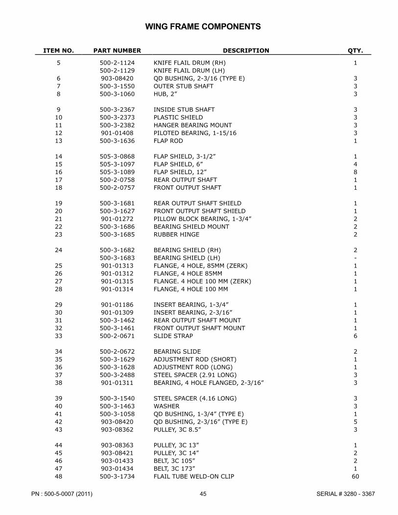
45PN : 500-5-0007 (2011) SERIAL # 3280 - 3367
ITEM NO. PART NUMBER DESCRIPTION QTY.
5 500-2-1124 KNIFE FLAIL DRUM (RH) 1500-2-1129 KNIFE FLAIL DRUM (LH)
6 903-08420 QD BUSHING, 2-3/16 (TYPE E) 37 500-3-1550 OUTER STUB SHAFT 38 500-3-1060 HUB, 2” 3
9 500-3-2367 INSIDE STUB SHAFT 310 500-3-2373 PLASTIC SHIELD 311 500-3-2382 HANGER BEARING MOUNT 312 901-01408 PILOTED BEARING, 1-15/16 313 500-3-1636 FLAP ROD 1
14 505-3-0868 FLAP SHIELD, 3-1/2” 115 505-3-1097 FLAP SHIELD, 6” 416 505-3-1089 FLAP SHIELD, 12” 817 500-2-0758 REAR OUTPUT SHAFT 118 500-2-0757 FRONT OUTPUT SHAFT 1
19 500-3-1681 REAR OUTPUT SHAFT SHIELD 120 500-3-1627 FRONT OUTPUT SHAFT SHIELD 121 901-01272 PILLOW BLOCK BEARING, 1-3/4” 222 500-3-1686 BEARING SHIELD MOUNT 223 500-3-1685 RUBBER HINGE 2
24 500-3-1682 BEARING SHIELD (RH) 2500-3-1683 BEARING SHIELD (LH) -
25 901-01313 FLANGE, 4 HOLE, 85MM (ZERK) 126 901-01312 FLANGE, 4 HOLE 85MM 127 901-01315 FLANGE� 4 HOLE 100 MM (ZERK) 128 901-01314 FLANGE, 4 HOLE 100 MM 1
29 901-01186 INSERT BEARING, 1-3/4” 130 901-01309 INSERT BEARING, 2-3/16” 131 500-3-1462 REAR OUTPUT SHAFT MOUNT 132 500-3-1461 FRONT OUTPUT SHAFT MOUNT 133 500-2-0671 SLIDE STRAP 6
34 500-2-0672 BEARING SLIDE 235 500-3-1629 ADJUSTMENT ROD (SHORT) 136 500-3-1628 ADJUSTMENT ROD (LONG) 137 500-3-2488 STEEL SPACER (2�91 LONG) 338 901-01311 BEARING, 4 HOLE FLANGED, 2-3/16” 3
39 500-3-1540 STEEL SPACER (4�16 LONG) 340 500-3-1463 WASHER 341 500-3-1058 QD BUSHING, 1-3/4” (TYPE E) 142 903-08420 QD BUSHING, 2-3/16” (TYPE E) 543 903-08362 PULLEY, 3C 8�5” 3
44 903-08363 PULLEY, 3C 13” 145 903-08421 PULLEY, 3C 14” 246 903-01433 BELT, 3C 105” 247 903-01434 BELT, 3C 173” 148 500-3-1734 FLAIL TUBE WELD-ON CLIP 60
WING FRAME COMPONENTS
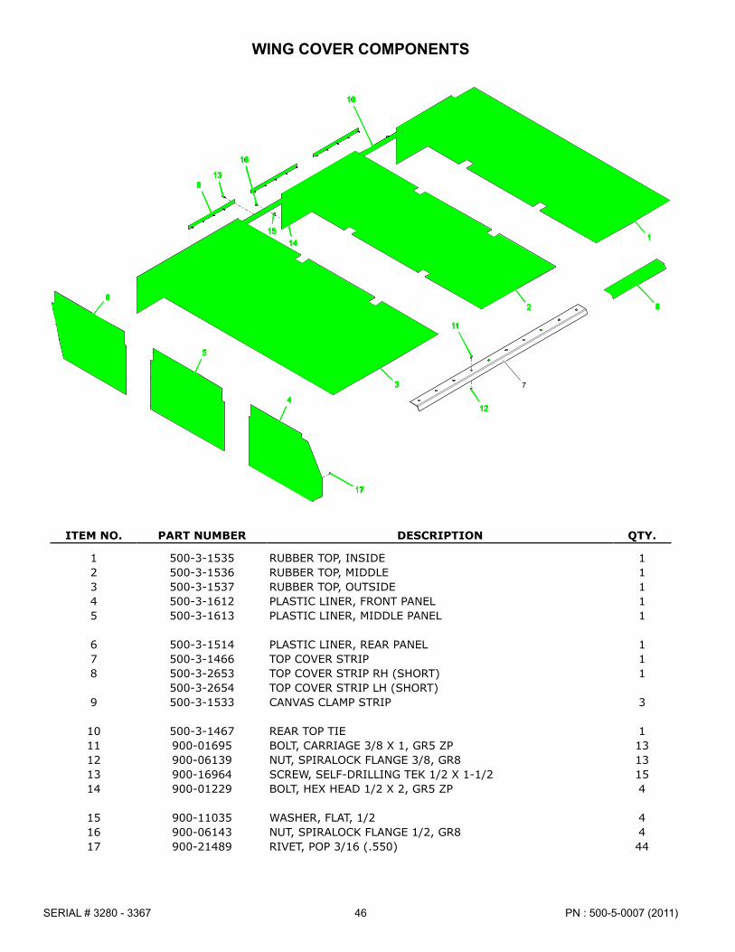
PN : 500-5-0007 (2011)46SERIAL # 3280 - 3367
WING COVER COMPONENTS
ITEM NO. PART NUMBER DESCRIPTION QTY.
1 500-3-1535 RUBBER TOP, INSIDE 12 500-3-1536 RUBBER TOP, MIDDLE 13 500-3-1537 RUBBER TOP, OUTSIDE 14 500-3-1612 PLASTIC LINER, FRONT PANEL 15 500-3-1613 PLASTIC LINER, MIDDLE PANEL 1
6 500-3-1514 PLASTIC LINER, REAR PANEL 17 500-3-1466 TOP COVER STRIP 18 500-3-2653 TOP COVER STRIP RH (SHORT) 1
500-3-2654 TOP COVER STRIP LH (SHORT)9 500-3-1533 CANVAS CLAMP STRIP 3
10 500-3-1467 REAR TOP TIE 111 900-01695 BOLT, CARRIAGE 3/8 X 1, GR5 ZP 1312 900-06139 NUT, SPIRALOCK FLANGE 3/8, GR8 1313 900-16964 SCREW, SELF-DRILLING TEK 1/2 X 1-1/2 1514 900-01229 BOLT, HEX HEAD 1/2 X 2, GR5 ZP 4
15 900-11035 WASHER, FLAT, 1/2 416 900-06143 NUT, SPIRALOCK FLANGE 1/2, GR8 417 900-21489 RIVET, POP 3/16 (�550) 44
10
13
16
9
1514
1
2 86
73
12
5
11
4
17

47PN : 500-5-0007 (2011) SERIAL # 3280 - 3367
BELT ASSEMBLY COMPONENTS
12
7 3 1 6 4 3
6 5 6 5 6 3
WING VIEW - RIGHT SIDE R O T A T I O N
R O
T A
T I O N
R O
T A
T I O N
7 3 1 4 6 3
3 6 5 6 5 6
2 1
WING VIEW - LEFT SIDER O T A T I O N
R O T A T I O N
R O
T A
T I O N
ITEM NO. PART NUMBER DESCRIPTION QTY.
1 903-01433 BELT, 3C105, HY-T TORQUE TEAM 22 903-01434 BELT, XC175, HY-T TORQUE TEAM 13 903-08362 SHEAVE, QD, 3C8�5-E 34 903-08363 SHEAVE, QD, 3C13�0-E 15 903-08421 SHEAVE, QD, 3C14�0-E 1
6 903-08420 BUSHING, QD, 2-3/16, TYPE E 57 500-3-1058 BUSHING, QD, 1-3/4, TYPE E 1

PN : 500-5-0007 (2011)48SERIAL # 3280 - 3367
WING STRUT COMPONENTS
ITEM NO. PART NUMBER DESCRIPTION QTY.
1 500-2-0686 MOUNTING ANGLE 12 500-2-0763 WING STRUT (SINGLE TIRE)3 500-2-1121 WING STRUT (DUAL TIRE)4 700-2-0165 HUB & SPINDLE ASSEMBLY 1 - 2
5 700-2-0168 TIRE & RIM ASSY (RH) 1905-09130 TIRE, 12�4-24 -905-09127 RIM, 24 x 10 -
6 700-2-0167 TIRE & RIM ASSY (LH) 1905-09130 TIRE, 12�4-24 -905-09127 RIM, 24 x 10 -
7 901-01318 BUSHING 28 500-3-2257 STRUT PIN 19 905-15024 STRAIGHT ZERK, 1/4-28 110 905-23014 RATCHET JACK 111 500-3-2202 RATCHET JACK LOCK 1
12 900-42065 SNAP PIN 113 900-11040 FLAT WASHER, 1” 214 500-3-2203 RATCHET JACK PIN 115 900-01437 BOLT, 3/4 NC x 8-1/2 416 900-03463 EYE BOLT, 3/4 NC x 6 4
17 900-11017 WASHER LOCK, 3/4 818 900-06015 NUT, 3/4 NC 8
5 4
318
4
17
18
17
16
15
2
6
7 4
7
1310
11
1413
12
1
8
6
9

49PN : 500-5-0007 (2011) SERIAL # 3280 - 3367
FLAIL COMPONENTS
ITEM NO. PART NUMBER DESCRIPTION QTY.
1 500-2-0067 FAIL MTG BRACKET WELD HALF -2 500-3-0316 RUBBER FLAIL -3 500-3-0151 SPACER, 1”, RUBBER FLAIL -4 500-2-0068 PIN WELD, RUBBER FLAIL -5 500-2-0069 PIN WELD, EXTENTION, RUBBER FLAIL -
6 900-11131 WASHER, NYLON 5/8 -7 900-29153 PIN, ROLL 7/32 X 1-1/2 -8 900-23041 PIN, COTTER 3/16 X 1 -9 900-06500 NUT, LOCK 3/8 NC -10 900-01105 BOLT, HEX HEAD 3/8 NC X 3/4, GR5 ZP -
11 900-01363 BOLT, HEX HEAD 5/8 NC X 4-1/2, GR5 ZP -12 900-11015 WASHER, LOCK 5/8 -13 900-06013 NUT, HEX HEAD 5/8 NC -14 505-3-0001 L-KNIFE (SMALL HOLE) -15 500-3-1735 L-KNIFE (LARGE HOLE) -
16 505-3-0004 STEEL CUP KNIFE, SHORT 7” (2008 - PRESENT) -17 505-3-0972 STEEL CUP KNIFE, SHORT 6-3/16” (PAST - 2007) -18 500-3-2134 SPACER, SMALL HOLE -19 500-3-1736 SPACER, LARGE HOLE -20 500-3-1733 BUSHING -
21 505-3-0405 BUSHING, WEAR -22 900-03064 BOLT, CARRIAGE 5/8 NC X 3-3/4, GR8 ZP (PARTIAL THREAD) -23 900-01792 BOLT, CARRIAGE 5/8 NC X 3-1/2, GR5 ZP (PARTIAL THREAD) -24 900-11037 WASHER, FLAT 5/8 -25 900-06508 NUT, TOP LOCK 5/8 NC, GR8 -
26 900-06145 NUT, SPIRALOCK FLANGE 5/8 NC, GR8 -
13
2
97
2
1213
26
11
2
8
4
10
7
5
626
20
15
19
23
L-KNIFE (PAST - 2006)
2524
18
14
18
22
L-KNIFE (2007 - PRESENT)
2216
21
17
25
CUP KNIFE
RUBBER (6-5-6) W/ EXT
13
12
11
1
2
3
2
9
8
4
410
RUBBER (6-5)
13
12
11
13
2
9
3
2
84
10
4
RUBBER (4-5)

PN : 500-5-0007 (2011)50SERIAL # 3280 - 3367
16
12
13
12
4
5
410
11
8
3
17
7
216
1716 13
9
7
18
15
4
14
5
6
17
1
17161514
4
6
FIXED STRUT COMPONENTS

51PN : 500-5-0007 (2011) SERIAL # 3280 - 3367
ITEM NO. PART NUMBER DESCRIPTION QTY.
1 500-2-0657 CENTER STRUT (22”) 12 500-2-1167 UPPER PIVOT CENTER STRUT 13 500-2-1042 SPINDLE HOLDER (30”) 1
500-2-1274 SPINDLE HOLDER (40”)500-2-1151 SPINDLE HOLDER (44”)
4 700-2-0165 HUB & SPINDLE ASSY 25 700-2-0167 TRACTION TIRE ASSY (LH) 1
905-09130 - TIRE, 12�4 X 24905-09127 - RIM, 24 x 10 x 8 BOLT
6 700-2-0168 TRACTION TIRE ASSY (RH) 1905-09130 - TIRE, 12�4 X 24905-09127 - RIM, 24 x 10 x 8 BOLT
7 500-3-1151 PIVOT BUSHING (BRONZE) 28 500-3-2236 PIVOT BUSHING (STEEL) 1
9 900-01541 BOLT, 1 NC x 7-1/2 110 900-06019 LNUT, 1 NC 111 900-11021 LOCK WASHER, 1” 112 900-01241 BOLT, 1/2 NC x 3-1/2 213 900-06504 TOPLOCK NUT, 1/2 NC 2
14 900-01437 BOLT, 3/4 NC x 8-1/2 415 900-03463 EYE BOLT, 3/4 NC x 6 416 900-11017 LOCK WASHER, 3/4” 817 900-06015 NUT, 3/4 NC 818 905-15024 STRAIGHT ZERK, 1/4-28 2
FIXED STRUT COMPONENTS
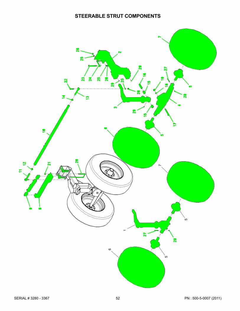
PN : 500-5-0007 (2011)52SERIAL # 3280 - 3367
STEERABLE STRUT COMPONENTS
28
20
89
21
6
5
11
6
2625
12
2625
2
24 195
18
1629
23
4
29
27
1529
27
28
17
15
10
26
25
55
3
1
14 13
77
22
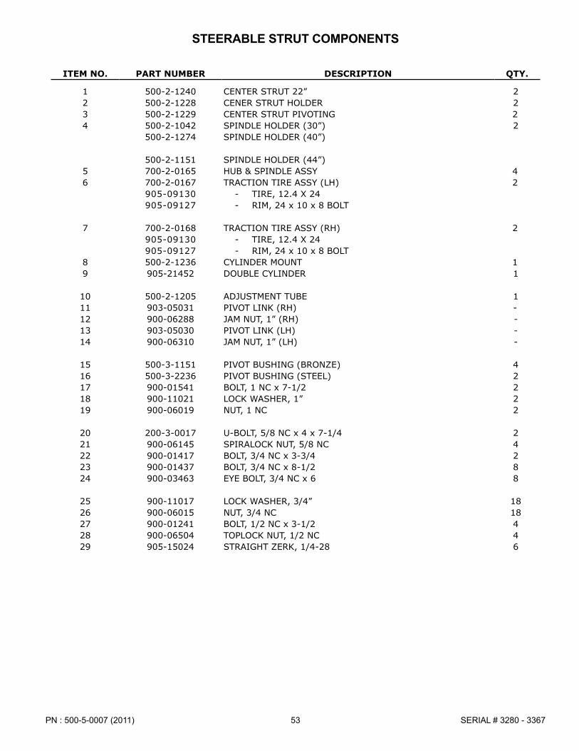
53PN : 500-5-0007 (2011) SERIAL # 3280 - 3367
ITEM NO. PART NUMBER DESCRIPTION QTY.
1 500-2-1240 CENTER STRUT 22” 22 500-2-1228 CENER STRUT HOLDER 23 500-2-1229 CENTER STRUT PIVOTING 24 500-2-1042 SPINDLE HOLDER (30”) 2
500-2-1274 SPINDLE HOLDER (40”)
500-2-1151 SPINDLE HOLDER (44”)5 700-2-0165 HUB & SPINDLE ASSY 46 700-2-0167 TRACTION TIRE ASSY (LH) 2
905-09130 - TIRE, 12�4 X 24905-09127 - RIM, 24 x 10 x 8 BOLT
7 700-2-0168 TRACTION TIRE ASSY (RH) 2905-09130 - TIRE, 12�4 X 24905-09127 - RIM, 24 x 10 x 8 BOLT
8 500-2-1236 CYLINDER MOUNT 19 905-21452 DOUBLE CYLINDER 1
10 500-2-1205 ADJUSTMENT TUBE 111 903-05031 PIVOT LINK (RH) -12 900-06288 JAM NUT, 1” (RH) -13 903-05030 PIVOT LINK (LH) -14 900-06310 JAM NUT, 1” (LH) -
15 500-3-1151 PIVOT BUSHING (BRONZE) 416 500-3-2236 PIVOT BUSHING (STEEL) 217 900-01541 BOLT, 1 NC x 7-1/2 218 900-11021 LOCK WASHER, 1” 219 900-06019 NUT, 1 NC 2
20 200-3-0017 U-BOLT, 5/8 NC x 4 x 7-1/4 221 900-06145 SPIRALOCK NUT, 5/8 NC 422 900-01417 BOLT, 3/4 NC x 3-3/4 223 900-01437 BOLT, 3/4 NC x 8-1/2 824 900-03463 EYE BOLT, 3/4 NC x 6 8
25 900-11017 LOCK WASHER, 3/4” 1826 900-06015 NUT, 3/4 NC 1827 900-01241 BOLT, 1/2 NC x 3-1/2 428 900-06504 TOPLOCK NUT, 1/2 NC 429 905-15024 STRAIGHT ZERK, 1/4-28 6
STEERABLE STRUT COMPONENTS
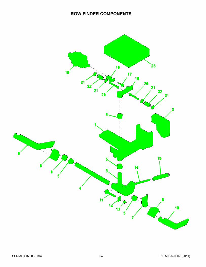
PN : 500-5-0007 (2011)54SERIAL # 3280 - 3367
ROW FINDER COMPONENTS
10
18
9
8
65
15
4
14
2
1
3
5
5
7
19
81112
2122
13
21
17
5
20
1620
2122
21
23

55PN : 500-5-0007 (2011) SERIAL # 3280 - 3367
ROW FINDER COMPONENTS
ITEM NO. PART NUMBER DESCRIPTION QTY.
1 500-2-1249 PIVOT MOUNT 12 700-3-2186 INNER PIVOT MOUNT 13 700-2-0851 BOTTOM PIVOT 14 700-3-2170 PIVOT SHAFT 15 700-3-0383 BUSHING (OILITE) 4
6 700-3-2182 LOCK COLLAR 17 700-2-0853 SPRING TENSIONER 18 700-2-0854 FINGER MOUNT 29 700-3-2188 FINGER (LH) 110 700-3-2189 FINGER (RH) 1
11 900-03465 EYE BOLT 112 700-3-2187 INSIDE WASHER 113 700-3-2183 BUSHING (TENSIONER) 114 700-2-0856 TENSIONER ROD 115 905-14007 TENSIONER SPRING 1
16 700-2-0850 STEERING PADDLE 117 903-05044 ROD END EYE BOLT 118 700-3-2343 ADJUSTMENT PLATE 119 905-03262 CONTROL VALVE 120 900-01245 BOLT, 1/2 NC x 4 2
21 700-3-2185 SPRING RETAINER 422 905-14022 SPRING 223 500-2-1250 TOP COVER 1
- 500-2-1248 ROWFINDER COMPLETE ASSEMBLY -
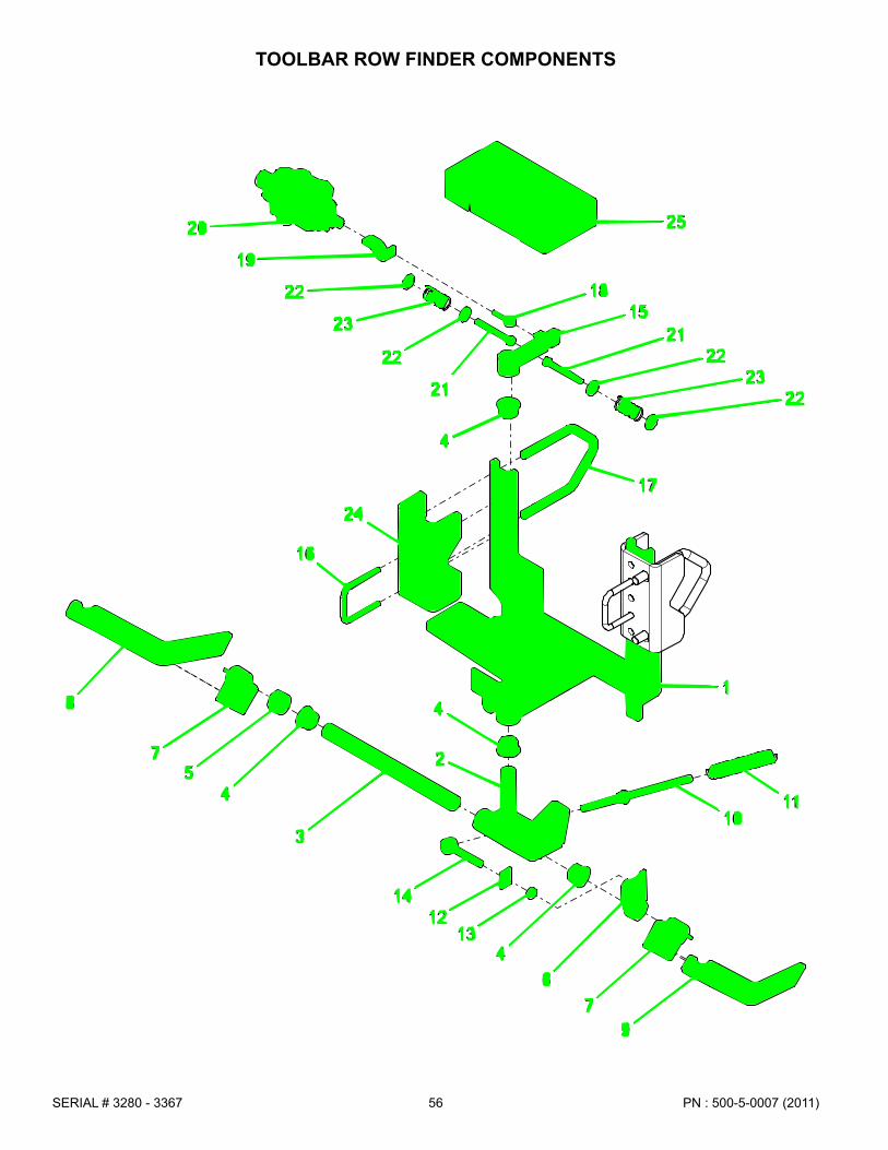
PN : 500-5-0007 (2011)56SERIAL # 3280 - 3367
TOOLBAR ROW FINDER COMPONENTS
8
23
7
11
54
103
17
2
4
41
6
20
24
14
79
19
1213
16
22 18
22
21
15
4
2122
2322
25
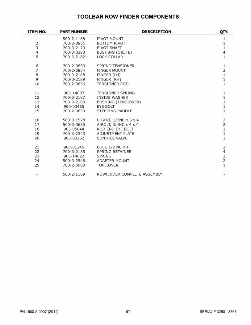
57PN : 500-5-0007 (2011) SERIAL # 3280 - 3367
ITEM NO. PART NUMBER DESCRIPTION QTY.
1 500-2-1168 PIVOT MOUNT 12 700-2-0851 BOTTOM PIVOT 13 700-3-2170 PIVOT SHAFT 14 700-3-0383 BUSHING (OILITE) 45 700-3-2182 LOCK COLLAR 1
6 700-2-0853 SPRING TENSIONER 17 700-2-0854 FINGER MOUNT 28 700-3-2188 FINGER (LH) 19 700-3-2189 FINGER (RH) 110 700-2-0856 TENSIONER ROD 1
11 905-14007 TENSIONER SPRING 112 700-3-2187 INSIDE WASHER 113 700-3-2183 BUSHING (TENSIONER) 114 900-03465 EYE BOLT 115 700-2-0850 STEERING PADDLE 1
16 500-3-1578 U-BOLT, 1/2NC x 3 x 4 217 500-3-0635 A-BOLT, 3/4NC x 4 x 4 218 903-05044 ROD END EYE BOLT 119 700-3-2343 ADJUSTMENT PLATE 120 905-03262 CONTROL VALVE 1
21 900-01245 BOLT, 1/2 NC x 4 222 700-3-2185 SPRING RETAINER 423 905-14022 SPRING 224 500-3-2548 ADAPTER MOUNT 225 700-2-0908 TOP COVER 1
- 500-2-1169 ROWFINDER COMPLETE ASSEMBLY -
TOOLBAR ROW FINDER COMPONENTS

PN : 500-5-0007 (2011)58SERIAL # 3280 - 3367
SCALPER ROW FINDER COMPONENTS
20
8
7
54
14
3
13
2
6
7
15
10
4
11
9
19
12
18
1
17
2122
21
4
20
16
2122
21
23
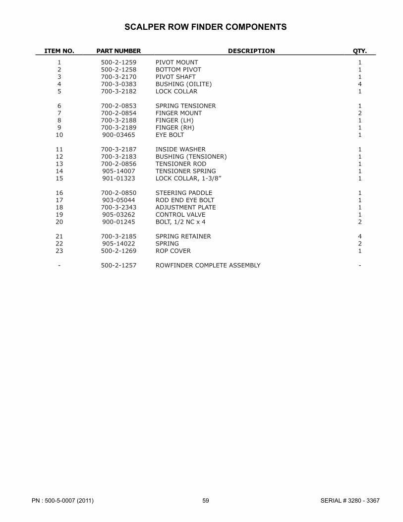
59PN : 500-5-0007 (2011) SERIAL # 3280 - 3367
ITEM NO. PART NUMBER DESCRIPTION QTY.
1 500-2-1259 PIVOT MOUNT 12 500-2-1258 BOTTOM PIVOT 13 700-3-2170 PIVOT SHAFT 14 700-3-0383 BUSHING (OILITE) 45 700-3-2182 LOCK COLLAR 1
6 700-2-0853 SPRING TENSIONER 17 700-2-0854 FINGER MOUNT 28 700-3-2188 FINGER (LH) 19 700-3-2189 FINGER (RH) 110 900-03465 EYE BOLT 1
11 700-3-2187 INSIDE WASHER 112 700-3-2183 BUSHING (TENSIONER) 113 700-2-0856 TENSIONER ROD 114 905-14007 TENSIONER SPRING 115 901-01323 LOCK COLLAR, 1-3/8” 1
16 700-2-0850 STEERING PADDLE 117 903-05044 ROD END EYE BOLT 118 700-3-2343 ADJUSTMENT PLATE 119 905-03262 CONTROL VALVE 120 900-01245 BOLT, 1/2 NC x 4 2
21 700-3-2185 SPRING RETAINER 422 905-14022 SPRING 223 500-2-1269 ROP COVER 1
- 500-2-1257 ROWFINDER COMPLETE ASSEMBLY -
SCALPER ROW FINDER COMPONENTS

PN : 500-5-0007 (2011)60SERIAL # 3280 - 3367
10
15
10
1617
8
10
12
3
410
6
1
9
2
5
9
11
7
11
14
9
13
9
11
11
ITEM NO. PART NUMBER DESCRIPTION QTY.
1 500-2-1080 UPPER MOUNT 12 500-2-1248 ROWFINDER 13 500-2-1081 H-ARM 14 500-3-0991 CONNECTING ARM (5/8” HOLES) 15 500-3-0992 CONNECTING ARM (3/4” HOLES) 1
6 500-2-1079 LOWER MOUNT 17 500-2-1029 HORIZONTAL MOUNT 18 905-21400 CYLINDER, 3-1/2 x 8 19 200-3-2631 PARALLEL LINK PIN 410 900-06145 SPIRALOCK NUT, 5/8 NC 4
11 900-06510 TOP LOCK NUT, 3/4 NC 412 200-3-1445 U-BOLT, 1/2 NC x 4 x 3 213 200-3-1447 U-BOLT, 1/2 NC x 2 x 5-1/4 214 900-06143 SPIRALOCK NUT, 1/2 NC 815 200-3-0024 U-BOLT, 3/4 NC x 6 x 5-1/2 2
16 900-11017 LOCK WASHER, 3/4 417 900-06015 NUT, 3/4 NC 4
- 500-1-0182 ROW FINDER REAR TUBE MOUNT KIT -
ROWFINDER PARALLEL LINK MOUNT

61PN : 500-5-0007 (2011) SERIAL # 3280 - 3367
ROWFINDER PARALLEL LINK MOUNT (44” STRUTS)
ITEM NO. PART NUMBER DESCRIPTION QTY.
1 500-2-1254 UPPER MOUNT 12 500-2-1248 ROW FINDER 13 500-2-1081 H-ARM 14 500-3-0991 CONNECTING ARM (5/8” HOLES) 15 500-3-0992 CONNECTING ARM (3/4” HOLES) 1
6 500-2-1255 LOWER MOUNT 17 500-2-1029 HORIZONTAL MOUNT 18 905-21400 CYLINDER, 3-1/2” x 8 19 200-3-2631 PARALLEL LINK PIN 410 900-06145 SPIRALOCK NUT, 5/8 NC 4
11 900-06510 TOP LOCK NUT, 3/4 NC 412 200-3-1445 U-BOLT, 1/2 NC x 4 x 3 213 200-3-1447 U-BOLT, 1/2 NC x 2 x 5-1/4 214 900-06143 SPIRALOCK NUT, 1/2 NC 815 900-01437 BOLT, 3/4 NC x 8-1/2 2
16 900-03463 EYE BOLT, 3/4 NC x 6 217 900-11017 LOCK WASHER, 3/4 418 900-06015 NUT, 3/4 NC
- 500-1-0366 ROW FINDER REAR TUBE MOUNT KIT (44” STRUTS) -
18
17
16
17
18
10
15
108
1
10
4
10
3
12
6
9
9
5
2
11
11
714
9
9
11
13
11

PN : 500-5-0007 (2011)62SERIAL # 3280 - 3367
HYDRAULIC COMPONENTS

63PN : 500-5-0007 (2011) SERIAL # 3280 - 3367
HYDRAULIC COMPONENTS
ITEM NO. PART NUMBER DESCRIPTION QTY.
1 905-03112 TEE, 6 MJIC 22 905-03114 90 DEG� ADAPTER, 6 MJIC X 3/4-16 MORB 9/133 905-03115 ADAPTER, 6 MJICX3/4-16 MORB 24 905-03124 ADAPTER, 8 MORB X 3/4 FPT 25 905-03126 TEE, 6 MJIC X 6 FJIC X 6 MJIC 1
6 905-03127 TEE, 6 MJIC X 6 MJIC X 6 FJIC 27 905-21400 3-1 /2 X 8 CYLINDER WITH DEPTH STOP 4/6
905-21401 SEAL KIT, 3-1/2X8905-21419 ROD
8 905-21395 4 X 24 CYLINDER (WING LIFT) 2905-21409 SEAL KIT, 4 X 24 2
9 905-03136 90 DEG ELBOW, 6 MJIC X 6 MPT W/ BEVEL 210 905-03140 CAP 411 905-03141 CROSS, 6 MJIC 212 905-19112 3/8” SWIVEL FLOW RESTRICTOR 1/16 213 905-19126 MALE HYDRAULIC COUPLER 6
14 905-19133 3/8” HOSE, 252” LONG, 6 FJIC X 8 MORB 215 905-19134 3/8” HOSE, 53-1/2” LONG, 6 FJIC X 6 FJIC 416 905-19135 3/8” HOSE, 58” LONG, 6 FJIC X 6 FJIC 217 905-19136 3/8” HOSE, 41-1/2” LONG, 6 FJIC X 6 FJIC 218 905-19127 3/8” HOSE, 300” LONG, 6 FJIC X 8 MORB 1
19 905-19138 3/8” HOSE, 324” LONG, 6 FJIC X 8 MORB 120 905-19139 3/8” HOSE, 150” LONG, 6 FJIC X 8 MORB 121 905-19140 3/8” HOSE, 138” LONG, 6 FJIC X 8 MORB 122 905-19141 3/8” HOSE, 50” LONG, 6 FJIC X 6 FJIC 123 905-19142 3/8” HOSE, 70” LONG, 6 FJIC X 6 FJIC 1
24 905-19143 3/8” HOSE, 130” LONG, 6 FJIC X 6 FJIC 225 905-19121 3/8” HOSE, 120” LONG, 6 FJIC SVL X 8 MORB 226 905-03114 90 DEG ELBOW, 6 MJIC X 3/4-16 MORB 227 905-21194 3 X 8 CYLINDER (OPTIONAL REAR STEER) 1
905-21379 SEAL KIT, 3 X 8 1
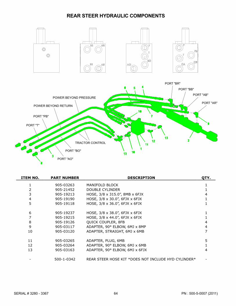
PN : 500-5-0007 (2011)64SERIAL # 3280 - 3367
POWER BEYOND RETURN
POWER BEYOND PRESSURE
45PORT "BR"
6 PORT "BB"
7
PORT "AB"
2
9
PORT "AR"
TRACTOR CONTROL
10
3
PORT "PB"
13
111
PORT "BO"
12
10
PORT "T"
13
PORT "AO"8
REAR STEER HYDRAULIC COMPONENTS
ITEM NO. PART NUMBER DESCRIPTION QTY.
1 905-03263 MANIFOLD BLOCK 12 905-21452 DOUBLE CYLINDER 13 905-19213 HOSE, 3/8 x 315�0”, 8MB x 6FJX 44 905-19190 HOSE, 3/8 x 30�0”, 6FJX x 6FJX 15 905-19118 HOSE, 3/8 x 36�0”, 6FJX x 6FJX 1
6 905-19237 HOSE, 3/8 x 38�0”, 6FJX x 6FJX 17 905-19215 HOSE, 3/8 x 44�0”, 6FJX x 6FJX 18 905-19126 QUICK COUPLER, 8FB 49 905-03117 ADAPTER, 90° ELBOW, 6MJ x 8MP 410 905-03120 ADAPTER, STRAIGHT, 6MJ x 6MB 7
11 905-03265 ADAPTER, PLUG, 6MB 512 905-03264 ADAPTER, 90° ELBOW, 6MJ x 6MB 113 905-03163 ADAPTER, 90° ELBOW, 6MJ x 6FJX 4
- 500-1-0342 REAR STEER HOSE KIT *DOES NOT INCLUDE HYD CYLINDER* -

65PN : 500-5-0007 (2011) SERIAL # 3280 - 3367
ROW FINDER HYDRAULIC COMPONENTS
PORT "BR"
PORT "BB"
PORT "AB"
PORT "AR"
POWER BEYOND PRESSURE
TRACTOR CONTROL
POWER BEYOND RETURN
PORT "PB"
PORT "BO"
2
2PORT "T"
PORT "T"
3
PORT "PB"
PORT "AO"
4
5
4
6
PORT "CB"
PORT "P"
1 3
PORT "CA"
ITEM NO. PART NUMBER DESCRIPTION QTY.
1 905-19155 HOSE, 3/8 x 120�0”, 6FJX x 6FJX 52 905-03120 ADAPTER, STRAIGHT, 6MJ x 6MB 63 905-03163 ADAPTER, 90° ELBOW, 6MJ x 6FJX 104 905-03210 ADAPTER, STRAIGHT, 6MJ x 12MB 35 905-03198 ADAPTER, STRAIGHT, 6MJ x 10MB 2
6 905-03220 ADAPTER, 1/16 RESTRICTOR, 6FJ x 6MJ 1
- 500-1-0343 ROW FINDER HOSE KIT -

PN : 500-5-0007 (2011)66SERIAL # 3280 - 3367
HUB & SPINDLE ASSEMBLY COMPONENTS
ITEM NO. PART NUMBER DESCRIPTION QTY.
1 905-09082 HUBB W/ CUPS (617) 12 2003-1240 FORK SPINDLE 13 901-01148 BEARING CUP 24 901-01149 BEARING CONE 25 901-09127 SEAL 2
6 900-06024 NUT, HEX HEAD 1-1/4 NF, ZP 17 900-06291 NUT, HEX HEAD, JAM 1-1/4 NF, ZP 18 200-3-1847 NUT, HEX HEAD, SHOULDER 1-1/4 NF 29 905-09134 NUT, HEX HEAD, WHEEL 9/16 NF 610 905-09136 HUB W/ CUPS (8-BOLT) 1
11 901-01324 BEARING CUP 112 901-01326 BEARING CONE 113 905-09067 WASHER, 7/8 SAE 114 900-06060 NUT, HEX HEAD, SLOTTED 7/8 NF 115 905-09135 HUB CAP 1
16 900-23064 PIN, COTTER 1/4 X 2 117 901-01152 BEARING CUP 118 901-01325 BEARING CONE 119 901-09215 SEAL 120 700-3-0143 SPINDLE 1
21 905-09011 NUT, HEX HEAD, WHEEL 1/2 NF
1
2
3
4
5
6
8
9
3
4
5
7
8
10
2118
17
19
20
11
12
13
14
15
16
617 HUB ASSEMBLY
8-BOLT HUB ASSEMBLY

67PN : 500-5-0007 (2011) SERIAL # 3280 - 3367
LIGHT COMPONENTS
ITEM NO. PART NUMBER DESCRIPTION QTY.
1 500-3-2196 WIRE HARNESS 12 904-01154 LAMP, AMBER 23 904-01155 LAMP, RED 24 500-3-1721 LIGHT, FIELD 25 500-2-0929 BRACKET, AMBER LAMP 2
6 500-3-1720 BRACKET, FIELD LIGHT 27 700-2-0151 BRACKET, LAMP (PART OF 500-2-0659) 28 500-3-2091 MOUNNT, SMV 19 500-3-1696 SIGN, SMNV 110 900-01009 BOLT, HEX HEAD 1/4 NC X 1, GR5 ZP 16
11 900-06496 NUT, TOP LOCK 1/4 NC 1812 900-35001 U-BOLT, 3/8 NC X 4 X 7 LG 213 900-06139 NUT, SERR FLANGE 3/8 NC 614 200-3-0017 U-BOLT, 5/8 NC X 4 X 7-1/4 LG 215 900-06145 NUT, SPIRALOCK FLANGE 5/8 NC GR8 4
16 900-35000 U-BOLT, 3/8 NC X 6 X 5 117 900-01005 BOLT, HEX HEAD 1/4 NC X 3/4, GR5 ZP 2
10
2
11
5 13
12
4
156
79
811
13
3
1417
16
1
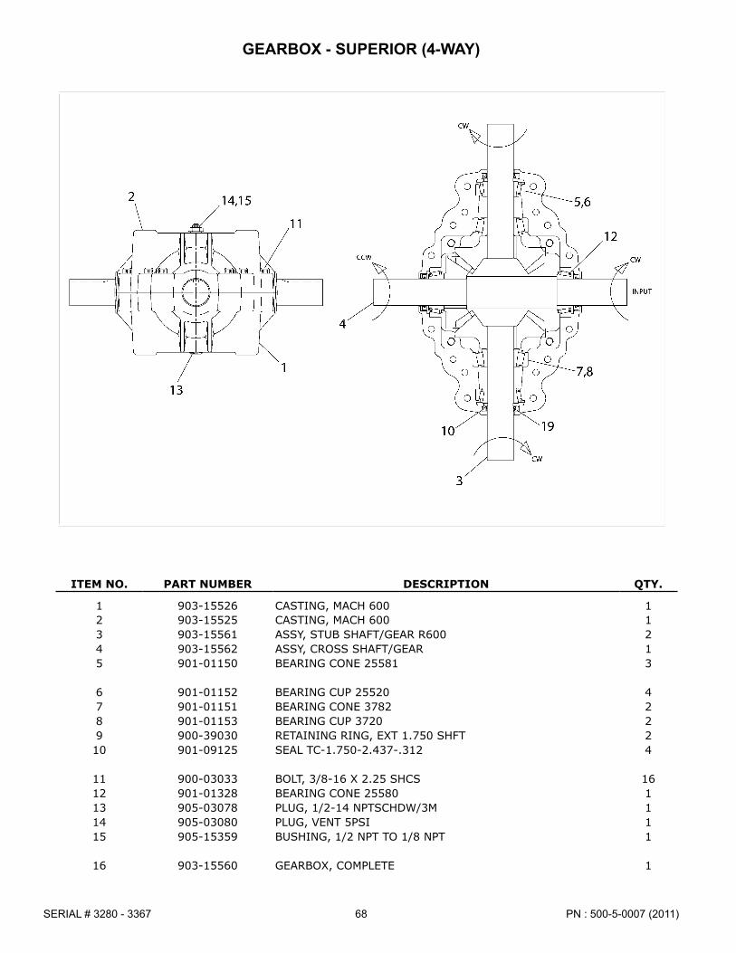
PN : 500-5-0007 (2011)68SERIAL # 3280 - 3367
GEARBOX - SUPERIOR (4-WAY)
ITEM NO. PART NUMBER DESCRIPTION QTY.
1 903-15526 CASTING, MACH 600 12 903-15525 CASTING, MACH 600 13 903-15561 ASSY, STUB SHAFT/GEAR R600 24 903-15562 ASSY, CROSS SHAFT/GEAR 15 901-01150 BEARING CONE 25581 3
6 901-01152 BEARING CUP 25520 47 901-01151 BEARING CONE 3782 28 901-01153 BEARING CUP 3720 29 900-39030 RETAINING RING, EXT 1�750 SHFT 210 901-09125 SEAL TC-1�750-2�437-�312 4
11 900-03033 BOLT, 3/8-16 X 2�25 SHCS 1612 901-01328 BEARING CONE 25580 113 905-03078 PLUG, 1/2-14 NPTSCHDW/3M 114 905-03080 PLUG, VENT 5PSI 115 905-15359 BUSHING, 1/2 NPT TO 1/8 NPT 1
16 903-15560 GEARBOX, COMPLETE 1

69PN : 500-5-0007 (2011) SERIAL # 3280 - 3367
ITEM NO. PART NUMBER DESCRIPTION QTY.
1 903-17639 Q�D� YOKE ASSEMBLY 22 903-17525 44R CROSS & BEARING KIT 23 903-18208 YOKE & SHAFT (1�31 SQ�) 14 903-18271 GUARD REPAIR KIT (NOT SHOWN) 15 903-17455 SAFETY SIGN 1
6 903-18276 OUTER GUARD 27 903-18277 INNER GUARD 18 903-18247 SAFETY SIGN (NOT SHOWN) 19 903-18248 GUARD REPAIR KIT (NOT SHOWN) 110 903-18209 YOKE, TUBE & SLIP SLEEVE 1
903-18207 GUARD SET
903-18198 JUMP PTO DRIVE SHAFT, COMPLETE
JUMP DRIVE SHAFT COMPONENTS

PN : 500-5-0007 (2011)70SERIAL # 3280 - 3367
1-3/8” PTO WWCV DRIVE SHAFT COMPONENTS
ITEM NO. PART NUMBER DESCRIPTION QTY.
1 903-18106 SSL / AUTO-LOK REPAIR KIT 12 903-18334 WWCV AUTO-LOK YOKE ASSEMBLY 13 903-18328 AB8/AW24/CAT 6 80° EBL CROSS KIT 24 903-18329 WWCV CENTER HOUSING 15 903-18415 WWCV YOKE & SHAFT (1�69-20) 1
6 903-18248 GUARD REPAIR KIT 17 903-17455 SAFETY SIGN 18 903-18361 OUTER GUARD 19 903-18362 INNER GUARD 110 903-17456 SAFETY SIGN 1
11 903-18363 YOKE, TUBE & SLIP SLEEVE 112 903-17239 55E CROSS KIT 113 903-18364 YOKE 1
903-18411 WWCV PTO DRIVE SHAFT, 1-3/8”, COMPLETE

71PN : 500-5-0007 (2011) SERIAL # 3280 - 3367
1-3/4” PTO WWCV DRIVE SHAFT COMPONENTS
ITEM NO. PART NUMBER DESCRIPTION QTY.
1 903-17772 SSL / AUTO-LOK REPAIR KIT 12 903-18327 WWCV AUOT-LOK YOKE ASSEMBLY 13 903-18328 AB8/AW24/CAT 6 80° EBL CROSS & BEARING KIT 24 903-18329 WWCV CENTER HOUSING 15 903-18418 WWCV YOKE & SHAFT (1�69-20) 1
6 903-18248 GUARD REPAIR KIT 17 903-17455 SAFETY SIGN 18 903-18371 OUTER GUARD 19 903-18372 INNER GUARD 110 903-17456 SAFETY SIGN 1
11 903-18373 YOKE, TUBE & SLIP SLEEVE 112 903-17239 55E CROSS & BEARING KIT 113 903-18364 YOKE 1
903-18412 WWCV PTO DRIVE SHAFT, 1-3/4”, COMPLETE

PN : 500-5-0007 (2011)72SERIAL # 3280 - 3367
WING DRIVE SHAFT COMPONENTS
ITEM NO. PART NUMBER DESCRIPTION QTY.
1 903-17639 YOKE 22 901-17525 44R CROSS & BEARING KIT 23 903-18079 YOKE & SHAFT (1�69-20) 14 903-17851 GUARD REPAIR KIT 25 903-18080 OUTER GUARD 1
6 903-18081 INNER GUARD 17 903-18082 YOKE, TUBE & SLIP SLEEVE 1
- 903-18055 WING DRIVE SHAFT, COMPLETE -

73PN : 500-5-0007 (2011) SERIAL # 3280 - 3367
ITEM NO. PART NUMBER DESCRIPTION QTY.
1 903-18364 YOKE 12 903-17239 55E CROSS & BEARING KIT 23 903-18378 YOKE & SHAFT (1�69-20) 14 903-17774 GUARD REPAIR KIT 25 903-17455 SAFETY SIGN 1
6 903-18379 OUTER GUARD 17 903-18380 INNER GUARD 18 903-17456 SAFETY SIGN 19 903-18381 YOKE, TUBE & SLIP SLEEVE 110 903-18382 OVERRUNNING CLUTCH ASM� 1
- 903-18308 HITCH EXTENSION DRIVE SHAFT, COMPLETE -
HITCH EXTENSION DRIVE SHAFT COMPONENTS

PN : 500-5-0007 (2011)74SERIAL # 3280 - 3367
SCALPER TOOLBAR COMPONENTS - STRAIGHT ARM
43
5
10
14
13
8
1
14
7
11
2
9
6
10
12
1610
5
14
15
9
11
8
1010
4
9
13
1211
8
10
ITEM NO. PART NUMBER DESCRIPTION QTY.
1 500-2-1234 CROSS TUBE 12 500-2-1231 MOUNT ARM (LH) 13 500-2-1233 MOUNT ARM (RH) 14 500-2-0692 WING SETBACK ARM W/O CYLINDER EAR 25 500-2-0691 WING SETBACK ARM W/ CYLINDER EAR 2
6 500-2-1109 CENTER SETBACK ARM W/O CYLINDER EAR 17 500-2-1108 CENTER SETBACK ARM W/ CYLINDER EAR 18 500-2-0696 SCALPER TUBE MOUNT W/O EAR 39 500-2-0695 SCALPER TUBE MOUNT W/ EAR 310 500-2-0684 1-1/4” PIN 6
11 500-3-2572 SCALPER TUBE 312 900-35026 U-BOLT, 5/8NC x 3 x 4-1/2 313 500-2-1144 WING SPREADER BAR 214 905-21400 CYLINDER, 3-1/2 x 8 315 900-01437 BOLT, 3/4NC x 8-1/2 12
16 900-03463 EYE BOLT, 3/4NC x 6 1217 500-3-4579 6” EXTENSION PLATE 218 900-01341 BOLT, 5/8NC x 1-1/2” 419 900-06145 SPIRALOCK NUT, 5/8NC 4
- 500-2-1232 CENTER MOUNT KIT *INCLUDES: #1 - #3* -- 500-1-0392 6” SCALPER SETBACK EXTENSION KIT *PER SET OF ARMS* -
1917
18
6” SCALPER SETBACK EXTENSION(FOR 44” STEARABLE STRUTS)

75PN : 500-5-0007 (2011) SERIAL # 3280 - 3367
SCALPER TOOLBAR COMPONENTS - PARALLEL LINK
12
43
5
14
10
13
8
1
14
7
12
2
11
9
6
1016 10
5
12
14
15
9
8
12
11
1010
4
12
9
13
12
11
8
10
ITEM NO. PART NUMBER DESCRIPTION QTY.
1 500-2-1234 CROSS TUBE 12 500-2-1231 MOUNT ARM (LH) 13 500-2-1233 MOUNT ARM (RH) 14 500-2-0692 WING SETBACK ARM W/O CYLINDER EAR 25 500-2-0691 WING SETBACK ARM W/ CYLINDER EAR 2
6 500-2-1109 CENTER SETBACK ARM W/O CYLINDER EAR 17 500-2-1108 CENTER SETBACK ARM W/ CYLINDER EAR 18 500-2-0942 SCALPER TUBE MOUNT W/O EAR 39 500-2-0941 SCALPER TUBE MOUNT W/ EAR 310 500-2-0684 1-1/4” PIN 6
11 500-3-2558 SCALPER TUBE 312 500-3-0635 A-BOLT, 3/4NC x 4 x 4 1213 500-2-1144 WING SPREADER BAR 214 905-21400 CYLINDER, 3-1/2 x 8 315 900-01437 BOLT, 3/4NC x 8-1/2 12
16 900-03463 EYE BOLT, 3/4NC x 6 12
- 500-2-1232 CENTER MOUNT KIT *INCLUDES: #1 - #3* -

PN : 500-5-0007 (2011)76SERIAL # 3280 - 3367
2
4
10
5
3
12
1311
11
6
8
9
10
7
1
14
21
1516
20
16
19
15
14
17
18
CIRCULAR KNIFE SCALPER - STRAIGHT ARM
ITEM NO. PART NUMBER DESCRIPTION QTY.
1 500-3-1754 MOUNT (RH) 12 500-3-1755 MOUNT (LH) 13 500-2-1139 PIVOT ARM 14 500-2-1068 SCALPER SHOE 15 500-2-0072 LIFT ROD 1
6 500-3-0172 RETAINING COLLAR 17 900-16063 SET SCREW, 1/2 N x 1-1/4 18 500-3-0157 SPRING 19 500-3-1756 SPRING RETAINER 110 500-3-1757 LIFT ROD CLAMP 2
11 500-3-1561 MOUNT SPACER 212 500-3-2411 PIVOT BUSHING 113 900-35026 U-BOLT, 5/8 NC x 3 x 4-1/2 214 500-3-2507 SHOE LINK BAR 215 500-3-2265 SHOE ADJUSTMENT ARM 2
16 500-3-1556 DISC SPACER 217 500-3-1557 DISC ADJUSTMENT ARM 118 500-2-1138 DISC MOUNT 119 905-09178 ROTARY DISC HUB 120 500-3-1940 DISC COVER 1
21 500-3-1582 ROTARY DISC 1

77PN : 500-5-0007 (2011) SERIAL # 3280 - 3367
12
31
11
6
4
2
10
7
9
8
5
ITEM NO. PART NUMBER DESCRIPTION QTY.
1 500-2-0330 UPPER MOUNT 12 500-2-0518 “H” LINKAGE ARM 13 500-3-0991 LINKAGE ARM (LH) 14 500-3-0992 LINKAGE ARM (RH) 15 500-2-0338 LOWER SHOE MOUNT 1
6 500-2-0335 SHOE (LH) 1500-2-0336 SHOE (RH)
7 500-3-0201 ECCENTRIC SPACER 18 500-3-0910 KNIFE SCALPER 19 200-3-2631 PIN 4
10 500-3-0675 EYE BOLT, 3�8 x 8 111 400-3-0263 EXTENSION SPRING 112 500-3-0635 A-BOLT, 3/4 NC x 4 x 4 1
STRAIGHT KNIFE SCALPER - PARALLEL ARM

PN : 500-5-0007 (2011)78SERIAL # 3280 - 3367
ITEM NO. PART NUMBER DESCRIPTION QTY.
1 500-2-0338 UPRIGHT WELD 12 900-11035 1/2 FLAT WASHER, ZP 23 900-11033 3/8 FLAT WASHER, ZP 14 900-11017 3/4 LOCK WASHER 25 400-3-0263 SPRING, GM AND ALLOWBOOM
6 900-06510 3/4 NC TOP LOCK NUT, ZP 47 500-2-0330 MOUNT WELD 18 900-06145 5/8 NC SPIRALOCK FLANGE NUT 59 900-06143 1/2 NC SPIRALOCK FLANGE NUT 610 900-06015 3/4 NC HEX NUT ZP 2
11 200-3-2631 PIN, PLATED 412 900-06005 3/8 NC HEX NUT, ZP 213 900-01245 1/2 NC X 4 HEX BOLT, GR5 114 900-01223 1/2 NC X 1-1/4 HEX BOLT 315 500-3-1563 PLATE, BRACKET, REAR TOP 2
16 500-2-0774 BRACKET, PIVOT 117 500-3-1557 STRAP, TOP REAR, ADJ� 118 500-3-1556 REAR SPACER TUBE 219 500-3-0992 BAR, 3/4 HOLES 120 500-3-0991 BAR, 5/8 HOLES 1
21 500-3-0675 3/8 EYE BOLT X 8” LONG 122 500-3-0635 A-BOLT, 3/4 X 4 X 4 123 500-2-0762 HUB ASSY, SCALPER 1
500-3-1582 DISC 1901-09219 HUB ASSY 1
901-09220 HUB REPAIR KIT 124 500-2-0704 SCALPER SHOE WELD 125 500-2-0518 H-WELD 126 900-01247 1/2 NC X 4-1/2 HEX BOLT GR5 2
CIRCULAR KNIFE SCALPER - PARALLEL ARM

79PN : 500-5-0007 (2011) SERIAL # 3280 - 3367
STABILIZER WHEEL COMPONENTS
ITEM NO. PART NUMBER DESCRIPTION QTY.
1 500-2-1128 UPPER ARM 12 200-2-0689 CASTER PIVOT BASE 13 200-3-2621 SIDE PLATE, LH 14 200-3-2622 SIDE PLATE, RH 1
5 200-2-0988 TIRE & WHEEL ASSEMBLY, 600 X 16SL MONORIB 1905-09019 - TIRE, 600 X 16 SINGLE RIB IMP905-09157 - RIM, 16 X 4�5E, 6 BOLT
6 200-2-0928 HUB & SPINDLE ASSEMBLY (617) - SEE PAGE 50 17 905-23014 RATCHET JACK, HEAVY DUTY 1
8 900-01221 BOLT, HEX HEAD, 1/2 NC X 1, GR5 ZP 19 900-01225 BOLT, HEX HEAD, 1/2 NC X 1-1/2, GR5 ZP 810 900-11013 WASHER, LOCK 1/2 911 200-3-1219 RETAINER PLATE 112 200-3-1766 BUSHING, OILITE, CASTER PIVOT 2
13 200-3-1233 WASHER, OILITE 114 900-01407 BOLT, HEX HEAD 3/4 NC X 2-1/2, GR5 ZP 215 500-3-2399 BUSHING, STEEL 216 900-06015 NUT, 3/4 NC 2
500-1-0290 STABILIZER WHEELS (PAIR)
9
3
6
10
5
16
7
1514
2
13
1
12
410
9
12
11
10
8

PN : 500-5-0007 (2011)80SERIAL # 3280 - 3367

81PN : 500-5-0007 (2011) SERIAL # 3280 - 3367
BOLT TORQUE CHARTSAE Series Torque ChartAlways tighten hardware to these values unless a different torque value or tightening procedure is listed for a specific application. Fasteners must always be replaced with the same grade as specified in the manual parts list.Make sure fastener threads are clean and you properly start thread engagement.
Metric Series Torque ChartUse only metric tools on metric hardware. Always tighten hardware to these values unless a different torque value or tightening procedure is listed for a specific application. Fasteners must always be replaced with the same grade.Make sure fastener threads are clean and you properly start thread engagement.
SAEBolt HeadIdentification
ADiameter(Inches)
WrenchSize
MARKING ON HEADSAE 2 SAE 5 SAE 8
ft./lb. (Nm) ft./lb. (Nm) ft./lb. (Nm)1/4” 7/16’ 6 (8) 10 (13) 14 (18)5/16’ 1/2” 12 (17) 19 (26) 27 (37)3/8” 9/16” 23 (31) 35 (47) 49 (67)
7/16” 5/8” 36 (48) 55 (75) 78 (106)1/2” 3/4” 55 (75) 85 (115) 120 (163)
9/16” 13/16” 78 (106) 121 (164) 171 (232)5/8” 15/16” 110 (149) 170 (230) 240 (325)3/4” 1-1/8” 192 (261) 297 (403) 420 (569)7/8” 1-5/16” 306 (416) 474 (642) 669 (907)1” 1-1/2” 350 (475) 680 (925) 1020 (1383)
1-1/8” 1-11/16” 450 (610) 885 (1200)1-1/4” 1-7/8” 600 (815) 1255 (1700)1-3/8” 2-1/16” 675 (915) 1620 (2200)1-1/2” 2-1/4’ 920 (1250) 2200 (2900)
A
Diameter & Thread
Pitch (Millimeters)
Wrench Size
COARSE THREAD FINE THREAD A
Diameter & Thread
Pitch (Millimeters)
MARKING ON HEAD MARKING ON HEAD
Metric 8.8 Metric 10.9 Metric 8.8 Metric 10.9
Nm ft./lb. Nm ft./lb. Nm ft./lb. Nm ft./lb.
6x1.0 10 mm 8 6 11 8 8 6 11 8 6x1.08x1.25 13 mm 20 15 27 20 21 16 29 22 8x1.010x1.5 16 mm 39 29 54 40 41 30 57 42 10x1.2512x1.75 18 mm 68 50 94 70 75 55 103 76 12x1.2514x2.0 21 mm 109 80 151 111 118 87 163 120 14x1.516x2.0 24 mm 169 125 234 173 181 133 250 184 16x1.518x2.5 27 mm 234 172 323 239 263 194 363 268 18x1.520 x 2.5 30 mm 330 244 457 337 367 270 507 374 20x1.522 x 2.5 34 mm 451 332 623 460 495 365 684 505 22 x 1.524 x 3.0 36 mm 571 421 790 583 623 459 861 635 24 x 2.030 x 3.0 46 mm 1175 867 1626 1199 1258 928 1740 1283 30 x 2.0

PN : 500-5-0007 (2011)82SERIAL # 3280 - 3367
ABBREVIATIONSAG ...................................................................AgricultureASAE ............ American Socity of Agricutural EngineersATF ...................................Automatic Transmission FluidBSPP ................................ British Standard Pipe ParallelBSPTM...................British Standard Pipe Tapered MaleCV ........................................................Constant VelocityCCW ................................................. Counter-ClockwiseCW ...................................................................ClockwiseDIA..................................................................... DiameterEP ........................................................Extreme PressureF ...........................................................................FemaleFB ...................................................Female O-Ring BossFJ ................................................................Female BossFJX .....................................................Female Swivel JICFP .................................................................Female Pipeft./lb ................................................................ Foot PoundGA ......................................................................... GaugeGR (5, etc.) ...............................................Grade (5, etc.)HHCS ............................................Hex Head Cap ScrewHT ................................................................Heat Treatedin .................................................................................InchJIC .................................Joint Industry Counicl 37° Flarekg ........................................................................Kilogramkm/h ................................................Kilometers Per Hourlb .............................................................................PoundLH ..................................................................... Left HandLT................................................................................ Leftin .............................................................................Inchesm .............................................................................Metermm ....................................................................MillimeterM .............................................................................. Male MB ...................................................... Male O-Ring Boss MJ.......................................................................Male JIC MJX ........................................................Male Swivel JIC MP ....................................................................Male Pipe MPa .............................................................Mega PascalMPH .........................................................Miles Per HourN ...........................................................................Newton
NC ..........................................................National CourseNF................................................................National FineNPSM ........................National Pipe Straight MechanicalNPT ..............................................National Pipe TaperedNPT SWF ............National Pipe Tapered Swivel FemaleNm ............................................................. Newton MeterOSHA ...Occupational Safety and Health AdministrationP ............................................................................... PitchPBY .......................................................... Power Beyondpsi ............................................. Pounds per Square InchPTO ......................................................... Power Take OffQD ........................................................Quick DisconnectRH ..................................................................Right HandROPS .............................. Roll Over Protection StructureRPM ...........................................Revolutions Per MinuteRT .............................................................................RightSAE .............................Society of Automotive EngineersSMV ............................................... Slow Moving VehicleUNC .........................................................Unified CoarseUNF ...............................................................Unified FineUNS ..........................................................Unified SpecialZP .....................................................................Zinc Plate

83PN : 500-5-0007 (2011) SERIAL # 3280 - 3367
GENERALAbbreviations ...................................................... 82Bolt Torque Chart ............................................... 81Check Lists ........................................................... 8General Information ............................................. 1Introduction ............................... Inside Front CoverProduct Warrenty ..................... Inside Back CoverReplacement Part Warranty .............................. 84Specifications ....................................................... 2Table of Contents ................................................. 1
OPERATION .................................................. 15 - 28Attaching to the Tractor ............................. 20 - 21Break-In of the Defoliator ................................. 18Defoliator Stored Position ................................ 28Disconnecting from Tractor ....................... 22 - 23Equipment Matching ..................................18 - 20
CV Driveline Turning Limits ...................... 19Drawbar with Clevis .................................. 19Electrical System ....................................... 19Hydraulic System ...................................... 19Mount and Dismount Tractor .................... 20PTO ........................................................... 18Tractor Ballast ........................................... 20
Field Operation .......................................... 25 - 26Entering the Field ...................................... 26Field Performance ..................................... 26Starting Defoliator ...................................... 26Stopping Defoliator .................................... 26
Lowering Wings to Operating Position ............ 24Pre-Operation Check List ................................ 17Principal Components ...................................... 16Raising Wings to Transport Position ............... 23Rear Steering (Optional) .................................. 27Scalpers (Optional) ................................... 27 - 28Transporting the Defoliator .............................. 28
OPERATOR SIGN-OFF RECORD ................ 9
OWNER SERVICE ...................................... 29 - 33Blocking Method ........................................ 29 - 30Lubrication ................................................. 30 - 31Maintenance .............................................. 32 - 33
Drive Belts ................................................. 32Flail Replacement ..................................... 33
PARTS INDEX .............................................. 35 - 77
SAFETY ...................................................................... 3Check Lists ......................................................... 10Decal Instructions .............................................. 8-9Maintenance ...................................................... 5-6Operation ........................................................... 4-5Operator Sign-Off Record ...................................11Preparation ........................................................... 3Storage ................................................................. 6Transporting ......................................................... 4
SAFETY DEALS .......................................... 10 - 13
SAFETY RULES .............................................. 3 - 7Maintenance .................................................. 6 - 7Operation ....................................................... 5 - 6Preparation .................................................... 3 - 4Storage ............................................................... 7Training ............................................................... 3Transporting .................................................. 4 - 5
TROUBLE SHOOTING .................................... 34
INDEX

PN : 500-5-0007 (2011)84SERIAL # 3280 - 3367
WARRANTY
Please Enter Information Below and Save For Future Reference.
Date Purchased: _____________________ From (Dealer): _________________________
Model Number: _______________________ Serial Number: __________________________
ALLOWAY STANDARD, d/b/a ALLOW AY, warrants this product to be free from defect in material and workmanship for TWELVE (12) MONTHS COMMENCING ON THE DATE OF DELIVERY OF THE PRODUCT TO THE ORIGINAL PURCHASER.
Under no circumstances will this Warranty apply in the event that the product, in the good faith opinion of ALLOWAY, has been subjected to improper operation, improper maintenance, misuse, or an accident. This Warranty does not apply in the event that the product has been materially modified or repaired by someone other than ALLOWAY, a ALLOWAY authorized dealer or distributor, and/or a ALLOWAY authorized service center; This Warranty does not cover normal wear or tear, or normal maintenance items. This Warranty also does not cover repairs made with parts other than those obtainable through ALLOWAY.
This Warranty is extended solely to the original purchaser of the product. Should the original purchaser sell or otherwise transfer this product to a third party, this Warranty does not transfer to the third party purchaser in any way. There are no third party beneficiaries of this Warranty.
ALLOWAY makes no warranty, express or implied, with respect to tires or other parts or accessories not manufactured by ALLOWAY. Their respective manufacturers, if any, provide warranties for these items, separately. ALLOWAY’S’ obligation under this Warranty is limited to, at ALLOWAYS’ option, the repair or replacement, free of charge, of the product if ALLOWAY, in its sole discretion, deems it to be defective or in noncompliance with this Warranty. The product must be returned to ALLOWAY with proof of purchase within thirty (30) days after such defect or noncompliance is discovered or should have been discovered, routed through the dealer and distributor from whom the purchase was made, transportation charges prepaid. ALLOWAY shall complete such repair or replacement within a reasonable time after ALLOWAY receives the product. THERE ARE NO OTHER REMEDIES UNDER THIS WARRANTY. THE REMEDY OF REPAIR OR REPLACEMENT IS THE SOLE AND EXCLUSIVE REMEDY UNDER THIS WARRANTY.
THERE ARE NO WARRANTIES, WHICH EXTEND BEYOND THE DESCRIPTION ON THE FACE OF THIS WARRANTY. ALLOWAY MAKES NO OTHER WARRANTY, EXPRESS OR IMPLIED, AND ALLOWAY SPECIFICALLY DISCLAIMS ANY IMPLIED WARRANTY OF MERCHANTABILITY AND/OR ANY IMPLIED WARRANTY OF FITNESS FOR A PARTICULAR PURPOSE.
ALLOWAY shall not be liable for any incidental or consequential losses, damages or expenses, arising directly or indirectly from the product, whether such claim is based upon breach of contract, breach of warranty, negligence, strict liability in tort or any other legal theory. Without limiting the generality of the foregoing. Alloway specifically disclaims any damages relating to (i) lost profits, business, revenues or goodwill; (ii) loss of crops; (iii) loss because of delay in harvesting; (iv) any expense or loss Incurred for labor, supplies, substitute machinery or rental; or (v) any other type of damage to property or economic loss.
This Warranty is subject to any existing conditions of supply, which may directly affect ALLOWAYS’ ability to obtain materials or manufacture replacement parts.
No agent, representative, dealer, distributor, serviceperson, salesperson, or employee of any company; including without limitation, ALLOWAY, its authorized dealers, distributors, and service centers, is authorized to alter, modify, or enlarge this Warranty.
This Warranty is effective only if the warranty registration card is returned within ten (10) days.
Answers to any questions regarding warranty service and locations may be obtained by contacting:Alloway4230 14th Ave.NWFargo, North Dakota 58102701-356-4983
PN : 500-5-0007 (2011) SERIAL # 3280 - 3367
WARRANTYALLOWAY STANDARD, d/b/a ALLOWAY, warrants this product to be free from defect in material and workmanship for a period of One (1) year, ninety (90) days for Service Parts, from the date of delivery of the product to the original purchaser.
Under no circumstances will this Warranty apply in the event that the product, in the good faith opinion of ALLOWAY, has been subjected to improper operation, improper maintenance, misuse, or an accident. This Warranty does not cover normal wear or tear, or normal maintenance items.
This Warranty is extended solely to the original purchaser of the product. Should the original purchaser sell or otherwise transfer this product to a third party, this Warranty does not transfer to the third party purchaser in any way. There are no third party beneficiaries of this Warranty.
ALLOWAY’S’ obligation under this Warranty is limited to, at ALLOWAY’S option, the repair or replacement, free of charge, of the product If ALLOWAY, in its sole discretion, deems it, to be defective or in noncompliance with this Warranty. The product must be returned to ALLOWAY with proof of purchase within thirty (30) days after such defect or noncompliance is discovered or should have been discovered, routed through the dealer and distributor from whom the purchase was made, transportation charges prepaid. ALLOWAY shall complete such repair or replacement within a reasonable time after ALLOWAY receives the product. THERE ARE NO OTHER REMEDIES UNDER THIS WARRANTY. THE REMEDY OF REPAIR OR REPLACEMENT IS THE SOLE AND EXCLUSIVE REMEDY UNDER THIS WARRANTY.THERE ARE NO WARRANTIES WHICH EXTEND BEYOND THE DESCRIPTION ON THE FACE OF THIS WARRANTY. ALLOWAY MAKES NO OTHER WARRANTY, EXPRESS OR IMPLIED, AND ALLOWAY SPECIFICALLY DISCLAIMS ANY IMPLIED WARRANTY OF MERCHANTABILITY AND/OR ANY IMPLIED WARRANTY OF FITNESS FOR A PARTICULAR PURPOSE.
ALLOWAY shall not be liable for any incidental or consequential losses, damages or expenses, arising directly or indirectly from the product, whether such claim is based upon breach of contract, breach, of warranty, negligence, strict liability in tort or any other legal theory. Without limiting the generality of the foregoing, Alloway specifically disclaims any damages relating to (i) lost profits, business, revenues or goodwill; (ii) loss of crops; (iii) loss because of delay in harvesting; (iv) any expense or loss incurred for labor, supplies, substitute machinery or rental; or (v) any other type of damage to property or economic loss.
This Warranty is subject to any existing conditions of supply, which may directly affect ALLOWAYS’ ability to obtain materials or manufacture replacement parts.
No agent, representative, dealer, distributor, service person, salesperson, or employee of any company, including without limitation, ALLOWAY, Its authorized dealers, distributors, and service centers, IS authorized to alter, modify, or enlarge this Warranty.
Answers to any questions regarding warranty service and locations may be obtained by contacting:
Alloway4230 14th Ave.NWFargo, North Dakota 58102701-356-4983

PN : 500-5-0007 (2011)SERIAL # 3280 - 3367
PART NUMBER
500-5-0007
Alloway Standard Industries Local/Intl: 1-701-356-49834230 14th Avenue NW Toll Free: 1-877-275-8714Fargo, North Dakota 58102 Fax: 1-701-356-4985
Quality • Innovation