Separator Manual-MMB 305
164
MMB 305S-11 Separator Manual High Speed Separator Product No. 881152-01-03 /2 Book No. 1271228-02 Rev. 4
description
Separator Manual-MMB 305
Transcript of Separator Manual-MMB 305

MMB 305S-11
Separator Manual
High Speed Separator
Product No. 881152-01-03 /2Book No. 1271228-02 Rev. 4

Published By:Alfa Laval Tumba ABSE-147 80 Tumba, Sweden
Telephone: +46 8 530 650 00Telefax: +46 8 530 310 40
© Alfa Laval Tumba AB 30 January 2008
This publication or any part there of may not be reproduced or transmitted by any process or means without prior written permission of Alfa Laval Tumba AB.

Contents
3
1 Read this first 7
2 Safety Instructions 9
2.1 Warning signs in text 14
2.2 Environmental issues 15
2.3 Requirements of personnel 16
3 Separator Basics 17
3.1 Basic principles of separation 18
3.2 Design and function 20
3.3 Definitions 27
4 Operating Instructions 29
4.1 Operating routine 30
5 Service Instructions 39
5.1 Periodic maintenance 40
5.2 Maintenance Logs 43
5.3 Check points at Intermediate Service 48
5.4 Check points at Major Service 57
5.5 3-year service 59
5.6 Lifting instructions 59
5.7 Cleaning 61
5.8 Oil change 64
5.9 Vibration 66
5.10 General directions 67
6 Dismantling/Assembly 71
6.1 Inlet/outlet and bowl 73
6.2 Bowl spindle and frame 87
6.3 Friction coupling 98

4
6.4 Flat belt and tightener 104
6.5 Oil filling device 109
6.6 Brake 110
6.7 Frame feet 112
7 Trouble-tracing 113
7.1 Trouble-tracing procedure 114
7.2 MMB mechanical function 115
7.3 Purification faults 120
7.4 Clarification faults 122
8 Technical Reference 123
8.1 Product description 124
8.2 Technical data 125
8.3 Basic size drawing 126
8.4 Connection list 128
8.5 Interface description 129
8.6 Quality specification, operating water 132
8.7 Lubricants 133
8.8 Drawings 145
8.9 Electric motor 146
8.10 Electric motor (Crompton Greaves) 148
8.11 Storage and installation 153
5
Read and understand instruction manuals and observe the warnings before installation, operation, service and maintenance.
Not following the instructions can result in serious accidents.
In order to make the information clear only foreseeable conditions have been considered. No warnings are given, therefore, for situations arising from the unintended usage of the machine and its tools.

6

7
1 Read this first
This manual is designed for operators and service engineers working with the Alfa Laval separator MMB 305S-11.
For information concerning the function of the separator, see Chapter ‘‘3 Separator Basics” on page 17, and Chapter ‘‘8 Technical Reference” on page 123.
If the separator has been delivered and installed by Alfa Laval as part of a processing system, this manual is a part of the System Manual. In this case, study carefully all the instructions in the System Manual.
In addition to this Separator Manual a Spare Parts Catalogue, SPC is supplied.
This Separator Manual consists of:
Safety Instructions
Pay special attention to the safety instructions for the separator. Not following the safety instructions can cause accidents resulting in damage to equipment and serious injury to personnel.
Separator Basics
Read this chapter if you are not familiar with this type of separator. This chapter contains the technical description and function description.
Operating Instructions
This chapter contains operating instructions for the separator only.
S00
6801
1
Separator Manual and Spare Parts Catalogue

1 Read this first
8
Service Instructions
This chapter gives instructions for daily checks, cleaning, oil changes, servicing and check points.
Dismantling / Assembly
This chapter contains step-by-step instructions for dismantling and assembly of the separator for service and repair.
Trouble-tracing
Refer to this chapter if the separator functions abnormally.
If the separator has been installed as part of a processing system always refer to the Trouble-tracing part of the System Manual first.
Technical Reference
This chapter contains technical data and drawings concerning the separator.
Index
This chapter contains an alphabetical list of subjects, with page references.

9
2 Safety Instructions
The centrifuge includes parts that rotate at high speed. This means that:
Kinetic energy is high
Great forces are generated
Stopping time is long
Manufacturing tolerances are extremely fine. Rotating parts are carefully balanced to reduce undesired vibrations that can cause a breakdown. Material properties have been considered carefully during design to withstand stress and fatigue.
The separator is designed and supplied for a specific separation duty (type of liquid, rotational speed, temperature, density etc.) and must not be used for any other purpose.
Incorrect operation and maintenance can result in unbalance due to build-up of sediment, reduction of material strength, etc., that subsequently could lead to serious damage and/or injury.
The following basic safety instructions therefore apply:
Use the separator only for the purpose and parameter range specified by Alfa Laval.
Strictly follow the instructions for installation, operation and maintenance.
Ensure that personnel are competent and have sufficient knowledge of maintenance and operation, especially concerning emergency stopping procedures.
Use only Alfa Laval genuine spare parts and the special tools supplied.
G00
1042
1S
0151
211

2 Safety Instructions
10
Disintegration hazards
When power cables are connected, always check direction of motor rotation. If incorrect, vital rotating parts could unscrew.
If excessive vibration occurs, stopseparator and keep bowl filled withliquid during rundown.
Use the separator only for the purpose and parameter range specified by Alfa Laval.
Check that the gear ratio is correct for power frequency used. If incorrect, subsequent overspeed may result in a serious break down.
Welding or heating of parts that rotate can seriously affect material strength.
Wear on the large lock ring thread must not exceed safety limit. -mark on lock ring must not pass opposite -mark by more than specified distance.
Inspect regularly for corrosion and erosion damage. Inspect frequently if process liquid is corrosive or erosive.
S01
512F
1S
0151
2N1
S01
512P
1S
0151
2L1
S01
5124
1S
0151
2G1
S01
512H
1

11
2 Safety Instructions
Entrapment hazards
Make sure that rotating parts have come to a complete standstill before starting any dismantling work.
To avoid accidental start, switch off and lock power supply before starting anydismantling work.
Assemble the machine completelybefore start. All covers and guards must be in place.
Electrical hazard
Follow local regulations for electrical installation and earthing (grounding).
To avoid accidental start, switch off and lock power supply before starting anydismantling work.
Crush hazards
Use correct lifting tools and follow lifting instructions.
Do not work under a hanging load.
S01
512O
1S
0151
261
S01
5127
1S
0151
2M1
S01
512Y
1

2 Safety Instructions
12
Noise hazards
Use ear protection in noisy environments.
Burn hazards
Lubrication oil and various machine surfaces can be hot and cause burns.
Skin irritation hazards
When using chemical cleaning agents, make sure you follow the general rules and suppliers recommendation regarding ventilation, personnel protection etc.
Use of lubricants in various situations.
S01
5129
1S
0151
2A1
S01
512D
1

13
2 Safety Instructions
Cut hazards
Sharp edges on bowl discs and threads can cause cuts.
Flying objects
Risk for accidental release of snap rings and springs when dismantling and assembly.
Health hazard
Risk for unhealthy dust when handling friction blocks/pads. Use a dust mask to make sure not to inhale any dust.
S01
512B
1S
0151
2C1
S01
512V
1

2 Safety Instructions
14
2.1 Warning signs in textPay attention to the safety instructions in this manual. Below are definitions of the three grades of warning signs used in the text where there is a risk for injury to personnel.
DANGER
Type of hazard
DANGER indicates an imminently hazardous situation which, if not avoided, will result in death or serious injury.
WARNING
Type of hazard
WARNING indicates a potentially hazardous situation which, if not avoided, could result in death or serious injury.
CAUTION
Type of hazard
CAUTION indicates a potentially hazardous situation which, if not avoided, may result in minor or moderate injury.
NOTE
NOTE indicates a potentially hazardous situation which, if not avoided, may result in property damage.
15
2 Safety Instructions
2.2 Environmental issues
Unpacking
Packing material consists of wood, plastics, cardboard boxes and in some cases metal straps.
Wood and cardboard boxes can be reused, recycled or used for energy recovery.
Plastics should be recycled or burnt at a licensed waste incineration plant.
Metal straps should be sent for material recycling.
Maintenance
During maintenance oil and wear parts in the machine are replaced.
Oil must be taken care of in agreement with local regulations.
Rubber and plastics should be burnt at a licensed waste incineration plant. If not available they should be disposed to a suitable licensed land fill site.
Bearings and other metal parts should be sent to a licensed handler for material recycling.
Seal rings and friction linings should be disposed to a licensed land fill site. Check your local regulations.
Worn out or defected electronic parts should be sent to a licensed handler for material recycling.
2 Safety Instructions
16
2.3 Requirements of personnel
Only skilled or instructed persons are allowed to operate the machine, e.g. operating and maintenance staff.
Skilled person: A person with technical knowledge or sufficient experience to enable him or her to perceive risks and to avoid hazards which electricity/mechanics can create.
Instructed person: A person adequately advised or supervised by a skilled person to enable him or her to perceive risks and to avoid hazards which electricity/mechanics can create.
In some cases special skilled personnel may need to be hired, like electricians and others. In some of these cases the personnel has to be certified according to local regulations with experience of similar types of work.

17
3 Separator Basics
Contents
3.1 Basic principles of separation 18
3.2 Design and function 20
3.2.1 Application 21
3.2.2 Design 22
3.2.3 Outline of function 22
3.2.4 Separating function 23
3.2.5 Water seal in the purificationmode 24
3.2.6 Displacement of oil 24
3.2.7 Gravity disc 24
3.2.8 Clarifier disc 24
3.2.9 Power transmission 25
3.2.10 Sensors and indicators 26
3.3 Definitions 27

3.1 Basic principles of separation 3 Separator Basics
18
3.1 Basic principles of separation
The purpose of separation can be:
to free a liquid of solid particles,
to separate two mutually insoluble liquids with different densities while removing any solids presents at the same time,
to separate and concentrate solid particles from a liquid.
Separation by gravity
A liquid mixture in a stationary bowl will clear slowly as the heavy particles in the liquid mixture sink to the bottom under the influence of gravity.
A lighter liquid rises while a heavier liquid and solids sink.
Continuous separation and sedimentation can be achieved in a settling tank having outlets arranged according to the difference in density of the liquids.
Heavier particles in the liquid mixture will settle and form a sediment layer on the tank bottom.
Centrifugal separation
In a rapidly rotating bowl, the force of gravity is replaced by centrifugal force, which can be thousands of times greater.
Separation and sedimentation is continuous and happens very quickly.
The centrifugal force in the separator bowl can achieve in a few seconds what takes many hours in a tank under influence of gravity.
G00
1071
1
Sedimentation by gravity
G00
1081
1
Sedimentation in a settling tank, with outlets making it possible to separate the lighter liquid parts from the heavier
G00
1091
1
The centrifugal solution

19
3 Separator Basics 3.1 Basic principles of separation
Separating temperatures
For some types of process liquids (e.g. mineral oils) a high separating temperature will normally increase the separation capacity. The temperature influences oil viscosity and density and should be kept constant throughout the separation.
Viscosity
Low viscosity facilitates separation. Viscosity can be reduced by heating.
Density difference
The greater the density difference between the two liquids, the easier the separation. The density difference can be increased by heating.
G00
1101
1
High viscosity (with low temperature)
G00
1111
1
Low viscosity (with high temperature)G
0011
211
High density (with low temperature)
G00
1131
1
Low density (with high temperature)

3.2 Design and function 3 Separator Basics
20
3.2 Design and function
G01
6572
1
Periodic maintenance is essentialPeriodic maintenance in accordance with theinstructions in this manual is essential for upholding correct running conditions and achieving anoptimal separation process. The following parts aresubject to maintenance at regular intervals:
1 Separator inlet, outlet, frame hood and bowl2 Bowl spindle and frame3 Friction coupling4 Flat belt and tightener5 Brake6 Oil filling device and sight glass7 Frame feet8 Electric motor

21
3 Separator Basics 3.2 Design and function
3.2.1 Application
The MMB 305S-11 is a high-speed centrifugal separator intended for marine and land applications. It is specifically designed for cleaning of mineral oils from water and solid particles (sludge).
It handles the following types of lubricating oils and low viscosity fuel oils:
Distillate, viscosity 1,5 - 5,5 cSt/40 °C.
Marine diesel oil, viscosity 13 cSt/40 °C.
Lubricating oil
R & O type
Detergent
Steam turbine
The cleaned oil is discharged continuously, while the solid particles are collected in the separator and have to be removed manually.
The separator can be operated either as a purifier or as a clarifier. When operated as a purifier the separator discharges the separated water. When the oil contains only small amounts of water the separator is operated as a clarifier, collecting the water together with the solid particles.
The separator has to be installed together with devices for control of start, stop, feed, back pressure and seal water.
WARNING
Disintegration hazards
Use the separator only for the purpose and parameters (type of liquid, rotational speed, temperature, density etc.) specified in chapter ‘‘8 Technical Reference” on page 123and in the Purchase Order documents.
Consult your Alfa Laval representative before any changes outside these parameters are made.
G01
6521
1
The MMB 305S-11 separator

3.2 Design and function 3 Separator Basics
22
3.2.2 Design
The separator comprises a frame consisting of the frame lower part (H), the intermediate part (E) and the frame top part (D) with a frame hood (B).
The separator bowl (C) is driven by an electric motor (G) via a flat-belt power transmission (L) and bowl spindle (F). The motor drive is equipped with a friction coupling (I) to prevent overload.
3.2.3 Outline of function
The separation process takes place in the rotating bowl. Unseparated oil is fed into the bowl through the inlet (201). The oil is cleaned in the bowl and leaves the separator through the outlet (220) via a paring chamber.
Impurities heavier than the oil are collected in the sludge space at the bowl periphery. The sludge has to be removed manually at regular intervals.
Permissible pressures and operating conditions are specified in chapter ‘‘8 Technical Reference” on page 123.
The processing parts of the separator are shown in the illustration on next page.
There are no contacting surfaces between process rotating parts (the bowl) and stationary parts (inlet, outlet, feed devices), and the interfacing surfaces are not sealed. As the separation process is carefully balanced regarding pressures and fluid levels, leakages will not occur as long as the correct running conditions are maintained.
G01
6532
1
Sectional viewMain parts, inlets and outlets
A Inlet and outletB Frame hoodC BowlD Frame top partE Frame intermediate partF Bowl spindleG Electric motorH Frame lower partI Friction couplingK BrakeL Flat beltM Frame feet
201 Oil inlet206 Inlet for liquid seal and displacement water220 Oil outlet221 Water outlet

23
3 Separator Basics 3.2 Design and function
3.2.4 Separating function
The separator can operate in one of two modes:
The purification mode in which three-phase separation takes place. The separated oil and water are continuously discharged from two separate outlets (220 and 221). The separated solid particles - the sludge - must be removed manually at appropriate intervals.
This is the most common mode of operation for this separator.
The clarification mode in which two-phase separation takes place. The oil is continuously separated from the heavy phase, consisting of water and sludge.
This is an optional mode of operation and is only suitable for oils containing very small amounts of water.
Separation takes place in the separator bowl to which uncleaned oil is fed through the oil inlet (201). The oil is distributed by the distributor (E) towards the periphery of the bowl.
When the unseparated oil reaches the slots in the distributor, it rises through the channels formed by the disc stack (G) where it is evenly distributed between the discs.
The oil is continuously separated from water and sludge as it travels towards the centre of the bowl. When the cleaned oil leaves the disc stack it rises upwards and enters the paring chamber. From there it is pumped by the paring disc (D) and leaves the bowl through the oil outlet (220).
Separated sludge (solid particles) and water –which are heavier – move towards the bowl periphery. In the purification mode, separated water rises along the outside of the disc stack, passes above the top disc up to the gravity disc (A) and leaves the bowl through the water outlet (221) of the separator.
The sludge collects in a sludge basket (J), which is emptied manually.
G01
6544
1
The bowl and the separating principle
201 Oil inlet206 Sealing and displacement water220 Oil outlet221 Water outletA Gravity discB Guiding coneC Paring chamber coverD Paring discE DistributorF Top discG Disc stackH Bowl hoodI Bowl bodyJ Sludge basket

3.2 Design and function 3 Separator Basics
24
3.2.5 Water seal in the purification mode
To prevent oil from escaping past the outer edge of the top disc (F) and through the water outlet (221), the bowl must be provided with a water seal. This is done by filling the bowl with water through the water inlet (206) before the uncleaned oil is fed to the separator. When the oil feed is turned on, the water is forced towards the bowl periphery and an interface (h1) is formed between the water and the oil. The position of this interface is determined by the inner diameter of a gravity disc (A).
3.2.6 Displacement of oil
To avoid oil losses when opening the bowl for cleaning, displacement water can be fed to the bowl. Before the separator is stopped, the oil feed is shut off and displacement water added through the water inlet (206). This water changes the liquid balance in the bowl, and the interface (h1) moves inwards to a new position, increasing the water volume in the sludge space. When the bowl is stopped, mainly water and sludge remains inside the bowl body.
3.2.7 Gravity disc
In the purification mode, the position of the interface (h1) can be adjusted by replacing the gravity disc (A) for one with larger or smaller diameter.
The correct gravity disc is selected from a nomogram, see ‘‘8.10.2 Gravity disc nomogram” on page 152.
3.2.8 Clarifier disc
In the clarification mode, the gravity disc is replaced by a clarifier disc which seals off the water outlet. In this case no water seal is required and consequently there is no oil/water interface in the bowl. The clarifier disc is an optional disc with a hole diameter of 40 mm. This disc is not shown in the nomograms.
G01
6553
1
Principle of liquid seal and displacement water in purificationh1 Oil/water interfaceA Gravity discF Top disc206 Water inlet221 Water outlet
G01
6561
1
Location of gravity disc and clarifier disc

25
3 Separator Basics 3.2 Design and function
3.2.9 Power transmission
Bowl spindle
In addition to its primary role in the power transmission system, the bowl spindle also serves as lubricator for spindle ball bearings.
The two spindle bearings are lubricated with oil mist. An oil pump (b3) creates the oil mist, which is sucked through the upper ball bearing by a fan (b1). Oil is supplied via an oil filling device, which also serves as a level indicator.
Two identical ring-shaped rubber buffers (b2) support the top bearing housing. The buffers are held in place by a buffer holder and form channels through which the recirculated oil passes.
Belt drive
The bowl spindle is driven by a flat belt. Adaptation to 50 or 60 Hz power supply is made by selecting the motor belt pulley with the appropriate diameter. A longer belt is needed for the pulley for 50 Hz.
Correct tension is set by means of a spring-loaded belt tightener.
Friction coupling
The friction coupling on the motor pulley ensures gentle start-up and prevents overload of the electric motor. Centrifugal force creates a torque that acts on the pulley through the friction elements.
G03
3741
1
Bowl spindle assembly and oil filling deviceB Bowl spindleb1 Fanb2 Rubber buffersb3 Oil pump
G01
1282
1
Belt drive
G01
1291
1
Friction coupling

3.2 Design and function 3 Separator Basics
26
Brake
The separator is equipped with a brake to be used when stopping the separator. The use of the brake reduces the retardation time of the bowl and critical speeds will therefore be quickly passed.
The brake friction element acts on the outside of the coupling pulley.
3.2.10 Sensors and indicators
Sight glass
The sight glass shows the oil level in the oil sump.
A
B
S00
2952
1
Brake on (A), brake off (B)

27
3 Separator Basics 3.3 Definitions
3.3 DefinitionsBack pressure Pressure in the separator outlet.
Clarification Liquid/solids separation with the intention of separating particles, normally solids, from a liquid having a lower density than the particles.
Clarifier disc An optional disc, which replaces the gravity disc in the separator bowl, in the case of clarifier operation. The disc seals off the heavy phase outlet in the bowl, thus no liquid seal exists.
Counter pressure See Back pressure.
Density Mass per volume unit. Expressed in kg/m3 at a specified temperature, normally at 15 °C.
Gravity disc Disc in the bowl hood for positioning the interface between the disc stack and the outer edge of the top disc. This disc is only used in purifier mode.
Interface Boundary layer between the heavy phase (water) and the light phase (oil) in a separator bowl.
Intermediate Service (IS)
Overhaul of separator bowl and inlet/outlet. Renewal of seals in bowl and inlet/outlet.
Major Service (MS) Overhaul of the complete separator, including bottom part (and activities included in an Intermediate Service). Renewal of seals and bearings in bottom part.
Phase Light phase: the lighter liquid separated, e.g. oil.Heavy phase: the heavier liquid separated, e.g. water.
Purification Liquid/liquid/solids separation with the intention of separating two intermixed and mutually insoluble liquid phases of different densities. Solids having a higher density than the liquids can be removed at the same time. The lighterliquid phase, which is the major part of the mixture, shall be purified as far as possible.
Sediment (sludge) Solids separated from a liquid.
Throughput The feed of process liquid to the separator per time unit.Expressed in m3/hour or litres/hour.
Viscosity Fluid resistance against movement. Normally expressed in centistoke(cSt = mm2/s), at a specified temperature.
Water seal Water in the solids space of the separator bowl to prevent the light phase (oil) from leaving the bowl through the heavy phase (water) outlet, in purifier mode.

3.3 Definitions 3 Separator Basics
28

29
4 Operating Instructions
Contents
4.1 Operating routine 30
4.1.1 Before first start 30
4.1.2 Selection of gravity disc 30
4.1.3 Start after a service 31
4.1.4 Before normal start 31
4.1.5 Starting and running-upprocedure 34
4.1.6 Separation 35
4.1.7 Stopping procedure 35
4.1.8 Safety stopI 36
4.1.9 Removal of separated sludge 37
4.1 Operating routine 4 Operating Instructions
30
4.1 Operating routineThese operating instructions describe routine procedures to follow before and during the start, running and stopping sequences of the separator.
If there is a System Manual, always follow the operating instructions of the System Manual. If there is no System Manual the instructions below are to be followed.
4.1.1 Before first start
Technical demands for connections and logical limitations for the separator are listed in chapter ‘‘8 Technical Reference” on page 123:
Technical data
Connection list
Interface description
Basic size drawing
Foundation drawing.
Before first start the following shall be checked:
1. Ensure the machine is installed correctly and that feed-lines and drains have been flushed clean.
2. Fill oil in the oil sump. Fill up to the middle of the sight glass. For grade and quality of oil see ‘‘8.7.3 Recommended lubricating oils” on page 140.
4.1.2 Selection of gravity disc
The separator is delivered with a set of gravity discs with different diameters for purification operation. The hole diameter of the gravity disc sets the position of the oil/water interface in the separator, see page 24. The separation efficiency can be optimized by selection of the correct diameter for each oil quality.

31
4 Operating Instructions 4.1 Operating routine
As a guide the ‘‘8.10.2 Gravity disc nomogram” on page 152 can be used. The hole diameter of the first gravity disc to be tried can be read directly from the nomogram. The best separation results are obtained by using a gravity disc with as large a hole diameter as possible.
When operating the separator as a clarifier the diameter of the disc should be 40 mm.
4.1.3 Start after a service
Pay special attention to unusual conditions when starting the separator after a service. Different fault symptoms are listed in chapter ‘‘7 Trouble-tracing” on page 113.
4.1.4 Before normal start
Check these points before every start.
1. Make sure that the bowl is clean and that the separator is properly assembled.
2. Make sure that the bolts of the outlet cover and the hooks and screws for the frame hood are fully tightened.
G01
6561
1
Location of gravity disc and clarifier disc
G02
8403
1
Check assembly and tightenings

4.1 Operating routine 4 Operating Instructions
32
3. Make sure that all couplings and connections are securely tightened to prevent leakage.
4. Make sure that the inlet pipe is tightened.
5. Read the oil level. The line in the middle of the sight glass shows the minimum level. Refill if necessary.
For grade and quality of oil see ‘‘8.7.3 Recommended lubricating oils” on page 140.
6. Release the brake (B).
S00
0982
1
Check for leakages (not admitted)
S00
0941
1
Check the oil level
A
B
S00
2954
1
Release the brake

33
4 Operating Instructions 4.1 Operating routine
7. Make sure the direction of rotation of the motor and bowl corresponds to the sign on the frame.
Remove the safety device A, see illustration. Look through the slot in the frame hood and make a quick start and stop. Correct rotational direction is clockwise.
WARNING
Disintegration hazards
If the direction of rotation is wrong, vital parts could unscrew.
G01
6653
1
Check that rotational direction of the bowl is clockwise

4.1 Operating routine 4 Operating Instructions
34
4.1.5 Starting and running-up procedure
1. Start the separator.
2. Be alert for unusual noises and conditions.
3. Note the normal occurrence of critical speed periods. Some vibrations occur for short periods during the starting cycle, when the separator passes through its critical speeds. This is normal and passes over without danger. Try to learn the vibration characteristics of the critical speed pattern.
4. Check the current to the separator motor to ensure that the separator has reached full speed:
During start, the current reaches a peak and then slowly drops to a low and stable value.
For normal length of the start-up period see ‘‘8.2 Technical data” on page 125.
WARNING
Disintegration hazards
When excessive vibration occurs, keep bowl filled and stop separator.
The cause of the vibration must be identified and rectified before the separator is restarted.
Excessive vibration may be due to incorrect assembly or insufficient cleaning of the bowl.
S00
0962
1
Current increases during start...
S00
0963
1
... to decrease to a stable value when full speed has been reached

35
4 Operating Instructions 4.1 Operating routine
5. For purification:
a. Supply water to form the water-seal. The water should have the same temperature as the process liquid and be supplied quickly.
b. Close the water feed when water flows out through the water outlet.
c. Start the oil feed slowly to avoid breaking the water seal. Then fill the bowl as quickly as possible.
6. For clarification:
a. Start the oil feed with full flow. Fill the bowl as quickly as possible.
7. For both purification and clarificationmodes:
Check the separator inlet and outlet pressures. See recommended values in your System Manual.
8. Adjust to desired throughput.
4.1.6 Separation
Do regular checks on:
oil inlet temperature (if applicable)
water collecting tank level (if applicable)
sound/vibration of the separator
back pressure
motor current.
4.1.7 Stopping procedure
1. Feed sealing water until water flows out through the water outlet. Then close this feed.
2. Turn off the oil feed.
3. Stop the separator.
G01
9373
1
Water outlet

4.1 Operating routine 4 Operating Instructions
36
4. Pull the brake (A).
Wait until the separator has come to a complete standstill (3-4 minutes).
Remove the safety device and look through the slot in the frame hood to see the movement of the bowl.
Release the brake when the separator is at standstill (B).
4.1.8 Safety stopI
f the separator begins to vibrate excessively during operation, stop it immediately by pushing the safety stop. The separator motor is switched off.
Keep the bowl filled during the run-down to minimize the excessive vibration.
Evacuate the room. The separator may be hazardous when passing its critical speeds during the run-down
WARNING
Entrapment hazards
Make sure that rotating parts have come to a complete standstill before starting anydismantling work.
NOTE
Manual cleaning must be carried out before next start up. See below, ‘‘4.1.9 Removal of separated sludge” on page 37.
A
B
S00
2953
1
The final action, pull the brake
S00
5111
1
The separator must not be dismantled before standstill
S00
5561
1
Hazard!
S00
0991
1

37
4 Operating Instructions 4.1 Operating routine
4.1.9 Removal of separated sludge
Separated sludge is collected in the sludge basket inside the bowl. Remove the sludge as follows:
1. Stop the separator.
2. Open the bowl. Follow the instructions in chapter ‘‘6 Dismantling/Assembly” on page 71.
3. Lift out the sludge basket and empty it.
4. Assemble.
The length of the periods between cleaning depends on the feed rate of the oil and on the quantity of solid particles in the oil. Guidelines for emptying intervals:
Marine diesel oil - 1 week
Lubricating oil - 1 day
The downtime is shortened if the basket with sludge is exchanged for a cleaned one.
CAUTION
Disintegration hazards
After a safety stop the cause of the fault must be identified.
If all parts have been checked and the cause remains unclear, contact Alfa Laval for advice.
NOTE
Appropriate intervals for a specific case must be based on experience.
4.1 Operating routine 4 Operating Instructions
38

39
5 Service Instructions
Contents
5.1 Periodic maintenance 40
5.1.1 Introduction 40
5.1.2 Maintenance intervals 40
5.1.3 Maintenance procedure 42
5.1.4 Service kits 42
5.2 Maintenance Logs 43
5.2.1 Daily checks 43
5.2.2 Oil change - monthly 44
5.2.3 IS - Intermediate Service 45
5.2.4 MS - Major Service 46
5.3 Check points at IntermediateService 48
5.3.1 Corrosion 48
5.3.2 Erosion 50
5.3.3 Cracks 51
5.3.4 Threads of inlet pipe, paring disc 52
5.3.5 Spindle top cone and bowlbody nave 53
5.3.6 Threads on bowl hood andbowl body 54
5.3.7 Disc stack pressure 56
5.4 Check points at Major Service 57
5.4.1 Paring disc height adjustment 57
5.4.2 Radial wobble of bowl spindle 58
5.5 3-year service 59
5.6 Lifting instructions 59
5.7 Cleaning 61
5.7.1 Cleaning agents 62
5.7.2 Cleaning of bowl discs 63
5.8 Oil change 64
5.8.1 Oil change procedure 64
5.9 Vibration 66
5.9.1 Vibration analysis 66
5.10 General directions 67
5.10.1 Ball and roller bearings 67
5.10.2 Before shut-downs 70

5.1 Periodic maintenance 5 Service Instructions
40
5.1 Periodic maintenance
5.1.1 Introduction
Periodic, preventive maintenance reduces the risk of unexpected stoppages and breakdowns. Maintenance logs are shown on the following pages in order to facilitate periodic maintenance.
5.1.2 Maintenance intervals
The following directions for periodic maintenance give a brief description of which parts to clean, check and renew at different maintenance intervals.
The Service Logs for each maintenance interval later in this chapter give detailed enumeration of the checks that must be done.
Daily checks consist of simple check points to carry out for detecting abnormal operating conditions.
Oil change interval is every 1500 hours or at least once every year if the total number of operating hours is less than 1500 hours.
Time of operation between oil changes can be extended from the normal 1500 hours to 2000 hours if a synthetic oil of group D is used.
In seasonal operation change the oil before a new period.
IS - Intermediate Service consists of an overhaul of the separator bowl, inlet and outlet every 3 months or 2000 operating hours. Seals in bowl and gaskets in the inlet/outlet device are renewed.
WARNING
Disintegration hazards
Separator parts that are worn beyond their safe limits or incorrectly assembled may cause severe damage or fatal injury.
41
5 Service Instructions 5.1 Periodic maintenance
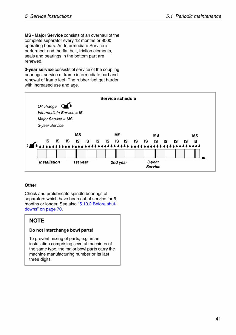
MS - Major Service consists of an overhaul of the complete separator every 12 months or 8000 operating hours. An Intermediate Service is performed, and the flat belt, friction elements, seals and bearings in the bottom part are renewed.
3-year service consists of service of the coupling bearings, service of frame intermediate part and renewal of frame feet. The rubber feet get harder with increased use and age.
Other
Check and prelubricate spindle bearings of separators which have been out of service for 6 months or longer. See also ‘‘5.10.2 Before shut-downs” on page 70.
NOTE
Do not interchange bowl parts!
To prevent mixing of parts, e.g. in an installation comprising several machines of the same type, the major bowl parts carry the machine manufacturing number or its last three digits.
2nd year
Oil change
Intermediate Service = IS
Major Service = MS
Service schedule
Installation 1st year
MS MS
3-year Service
MS MSIS IS IS IS IS IS IS IS IS IS IS IS IS IS IS IS
3-year Service

5.1 Periodic maintenance 5 Service Instructions
42
5.1.3 Maintenance procedure
At each Intermediate and Major Service, take a copy of the Service Log and use it for notations during the service.
An Intermediate and Major Service should be carried out in the following manner:
1. Dismantle the parts as mentioned in the Service Log and described in Chapter ‘‘6 Dismantling/Assembly” on page 71.
Place the separator parts on clean, soft surfaces such as pallets.
2. Inspect and clean the dismantled separator parts according to the Service Log.
3. Fit all the parts delivered in the Service kit while assembling the separator as described in chapter ‘‘6 Dismantling/Assembly” on page 71. The assembly instructions have references to check points which should be carried out during the assembly.
5.1.4 Service kits
Special service kits are available for Intermediate Service (IS) and Major Service (MS).
For other services the spare parts have to be ordered separately.
Note that the parts for IS are not included in the MS kit.
The contents of the service kits are described in the Spare Parts Catalogue.
NOTE
Always use Alfa Laval genuine parts as otherwise the warranty will become invalid.
Alfa Laval takes no responsibility for the safe operation of the equipment if non-genuine spare parts are used.
S00
2103
1
Spare parts kits are available for Intermediate Service and Major Service

43
5 Service Instructions 5.2 Maintenance Logs
5.2 Maintenance Logs
5.2.1 Daily checks
The following steps should be carried out daily.
Main component and activity Part Page Notes
Inlet and outlet
Check for leakage Connecting housing 32
Separator bowl
Check for vibration and noise 34
Belt transmission
Check for vibration and noise 34
Oil sump
Check Oil level 32
Electrical motor
Check for heat, vibration and noiseSee manufacturer’s instructions

5.2 Maintenance Logs 5 Service Instructions
44
5.2.2 Oil change - monthly
The oil change and check of belt transmission should be carried out every 1500 hours of operation.
When using a group D oil, time of operation between oil changes can be extended from the normal 1500 hours to 2000 hours.
When the separator is run for short periods, the lubricating oil must be changed every 12 months even if the total number of operating hours is less than 1500 hours (less than 2000 hours if a group D oil is used).
See chapter ‘‘8.7 Lubricants” on page 133 for further information on oil brands etc.
Main component and activity Part Page Notes
Bowl spindle and transmission
Check Belt tension 104
Change Oil in oil sump 64

45
5 Service Instructions 5.2 Maintenance Logs
5.2.3 IS - Intermediate Service
Name of plant: Local identification:
Separator: MMB 305S-11 Manufacture No./Year:
Total running hours: Product No.: 881152-01-03 /2
Date: Signature:
Renew all parts included in the Intermediate Service kit (IS) and do the following activities.
Main component and activity Part Page Notes
Inlet and outlet, frame
Clean and inspect Threads of inlet pipe 52
Paring disc 52
Housings and frame hood
Separator bowl
Clean and inspect Bowl hood 54
Top disc 63
Bowl discs 63
Distributor
Threads on bowl hood and bowl body
54
Bowl spindle cone and bowl body nave
53
Check Disc stack pressure 56
Galling of guide surface 54
Corrosion, erosion, cracks 48 - 50
Power transmission
Check Belt and belt tension 104
Change Oil in oil sump 64
Electrical motor
Lubrication (if nipples are fitted) See sign on motor
Signs and labels on separator
Check attachment and legibility Safety label on hood 150
Other plates and labels

5.2 Maintenance Logs 5 Service Instructions
46
5.2.4 MS - Major Service
Name of plant: Local identification:
Separator: MMB 305S-11 Manufacture No./Year:
Total running hours: Product No.: 881152-01-03 /2
Date: Signature:
Renew all parts included in the Intermediate and Major Service kits and do the following activities.
Main component and activity Part Page Notes
Inlet and outlet, frame
Clean and inspect Threads of inlet pipe 52
Paring disc 52
Housings and frame hood
Separator bowl
Clean and inspect Bowl hood 54
Top disc 63
Bowl discs 63
Distributor
Threads on bowl hood and bowl body
54
Bowl spindle cone and bowl body nave
53
Check Height of paring disc 57
Disc stack pressure 56
Galling of guide surface 54
Corrosion, erosion, cracks 48 - 50

47
5 Service Instructions 5.2 Maintenance Logs
Vertical driving device
Clean and inspect Oil mist fan 95
Oil pump 90
Bowl spindle 87
Ball bearing housing indentations
87
Check Radial wobble of bowl spindle 58
Oil sump
Clean Oil sump 64
Change Oil 64
Clean and inspect Oil filling device 109
Brake
Clean and inspect Brake 110
Friction coupling
Clean and inspect Friction coupling 111
Electrical motor
Replace Bearings1)
Signs and labels on separator
Check attachment and legibility Safety label on hood 150
Other signs and labels
1) See manufacturer’s instructions.
Main component and activity Part Page Notes

5.3 Check points at Intermediate Service 5 Service Instructions
48
5.3 Check points at Intermediate Service
5.3.1 Corrosion
Evidence of corrosion attacks should be looked for and rectified each time the separator is dismantled. Main bowl parts such as the bowl body and hood must be inspected with particular care for corrosion damage.
Always contact your Alfa Laval representative if you suspect that the largest depth of a corrosion damage exceeds 1,0 mm or if cracks have been found. Do not continue to use the separator until it has been inspected and given clearance for operation by Alfa Laval.
Cracks or damage forming a line should be considered as being particularly hazardous.
Non-stainless steel and cast iron parts
Corrosion (rusting) can occur on unprotected surfaces of non-stainless steel and cast iron. Frame parts can corrode when exposed to an aggressive environment.
WARNING
Disintegration hazard
Inspect regularly for corrosion damage. Inspect frequently if the process liquid is corrosive.
G01
7211
1
Main bowl parts to check for corrosion

49
5 Service Instructions 5.3 Check points at Intermediate Service
Stainless steel
Stainless steel parts corrode when in contact with either chlorides or acidic solutions. Acidic solutions cause a general corrosion. The chloride corrosion is characterised by local damage such as pitting, grooves or cracks. The risk of chloride corrosion is higher if the surface is
exposed to a stationary solution,
in a crevice,
covered by deposits,
exposed to a solution that has a low pH value.
A corrosion damage caused by chlorides on stainless steel begins as small dark spots that can be difficult to detect.
Inspect closely for all types of damage by corrosion and record these observations carefully.
Polish dark-coloured spots and other corrosion marks with a fine grain emery cloth. This may prevent further damage.
Other metal parts
Separator parts made of materials other than steel, such as brass or other copper alloys, can also be damaged by corrosion when exposed to an aggressive environment. Possible corrosion damage can be in the form of pits and/or cracks.
WARNING
Disintegration hazard
Pits and spots forming a line may indicate cracks beneath the surface.
All forms of cracks are a potential danger and are totally unacceptable.
Replace the part if corrosion can be suspected of affecting its strength or function.
S00
2061
1
Example of chloride corrosion in stainless steel
S00
2051
1
Polish corrosion marks to prevent further damage

5.3 Check points at Intermediate Service 5 Service Instructions
50
5.3.2 Erosion
Erosion can occur when particles suspended in the process liquid slide along or strike against a surface. Erosion can become intensified locally by flows of higher velocity.
Always contact your Alfa Laval representative if the largest depth of any erosion damage exceeds 1,0 mm. Valuable information as to the nature of the damage can be recorded using photographs, plaster impressions or hammered-in lead.
Erosion is characterised by:
Burnished traces in the material.
Dents and pits having a granular and shiny surface.
Parts of the bowl particularly subjected to erosion are:
The paring disc.
The top disc.
The underside of the distributor in the vicinity of the distribution holes and wings.
Look carefully for any signs of erosion damage. Erosion damage can deepen rapidly and consequently weaken parts by reducing the thickness of the metal.
WARNING
Disintegration hazard
Inspect regularly for erosion damage. Inspect frequently if the process liquid is erosive.
G02
0522
1
Maximum permitted erosion

51
5 Service Instructions 5.3 Check points at Intermediate Service
5.3.3 Cracks
Cracks can initiate on the machine after a period of operation and propagate with time.
Cracks often initiate in areas exposed to high cyclic material stresses. These cracks are called fatigue cracks.
Cracks can also initiate due to corrosion in an aggressive environment.
Although very unlikely, cracks may also occur due to the low temperature embrittlement of certain materials.
The combination of an aggressive environment and cyclic stresses will speed-up the formation of cracks. Keeping the machine and its parts clean and free from deposits will help to prevent corrosion attacks.
It is particularly important to inspect for cracks in rotating parts.
Always contact your Alfa Laval representative if you suspect that the largest depth of the damage exceeds 1,0 mm. Do not continue to use the separator until it has been inspected and cleared for operation by Alfa Laval.
WARNING
Disintegration hazard
All forms of cracks are potentially dangerous as they reduce the strength and functional ability of components.
Always replace a part if cracks are present.

5.3 Check points at Intermediate Service 5 Service Instructions
52
5.3.4 Threads of inlet pipe, paring disc
Damage to threads or a broken paring disc can prevent correct tightening of the inlet pipe and cause the paring disc to scrape against the top disc, even though the height adjustment of the paring disc has been made correctly.
1. Examine the threads for damage and rectify if required.
2. Examine the paring disc for damage and to see if the disc walls have parted. If they have, the inlet pipe has to be replaced with a new one.
G01
1302
1

53
5 Service Instructions 5.3 Check points at Intermediate Service
5.3.5 Spindle top cone and bowl body nave
Impact marks on the spindle cone or in the bowl body nave may cause the separator to vibrate while running.
Corrosion may cause the bowl to stick firmly to the spindle cone and cause difficulties during the next dismantling.
Remove any impact marks using a scraper and/or a whetstone.
Rust can be removed by using a fine-grain emery cloth (e.g. No. 320).
Finish with polishing paper (e.g. No. 600).
NOTE
Always use a scraper with great care. The conicity must not be marred.
G01
7231
1
Use whetstone or scraper with great care.

5.3 Check points at Intermediate Service 5 Service Instructions
54
5.3.6 Threads on bowl hood and bowl body
Excessive wear or impact marks on threads and guide surfaces of the bowl hood or bowl body may cause seizure damage.
Examine the thread condition by tightening the bowl hood after removing the disc stack and top disc from the bowl
When the bowl is new the alignment marks on the bowl hood and the bowl body should be aligned. If not, contact an Alfa Laval representative.
Wear
If thread wear is observed, mark the bowl body at the new position by punching a new alignment mark. If the mark on the bowl hood passes the mark on the bowl body by more than 25 , (A in the illustration) an Alfa Laval representative should be contacted immediately.
The measure A in millimetres (mm) is obtained by calculating bowl outside diameter D times 0,2.
If the marks are illegible, an Alfa Laval representative should be contacted for determination and punching of new alignment marks.
WARNING
Disintegration hazards
Wear on threads must not exceed safety limit. mark on bowl hood must not pass
mark on bowl body by more than 25 .
G01
7242
1
D
A
(MAX 25 )
G05
7811
1

55
5 Service Instructions 5.3 Check points at Intermediate Service
Damage
The position of threads, contact and guide surfaces are indicated by arrows in the illustration.
Examine for burrs and protrusions caused by impact.
Clean the threads, contact and guide surfaces with a suitable degreasing agent.
If damage is found, rectify by using a whetstone or fine emery cloth. Recommended grain size: 240.
If the damage is bad, use a fine single-cut file, followed by a whetstone.
After rectifying, the threading has to be primed with Molykote 1000.
CAUTION
Cut hazard
The threads have sharp edges which can cause cuts.
G01
7273
1
Contact surfaces to inspect on the bowl

5.3 Check points at Intermediate Service 5 Service Instructions
56
5.3.7 Disc stack pressure
The bowl hood exerts a pressure on the disc stack clamping it in place.
1. Place the bowl hood on the top of the disc stack and tighten it by hand.
The assembly mark on the bowl hood should now be positioned at the angle “a” (see illustration), 30° - 60° ahead of the corresponding mark on the bowl body.
2. If the bowl hood can be tightened by hand without resistance until the marks are in line with each other, an extra disc must be added to the top of the disc stack beneath the top disc.
3. Re-check the disc stack pressure if one or more discs have been added.
NOTE
Insufficient pressure in the disc stack may affect the bowl balance, which in turn will cause abnormal vibration of the separator and shorten the life of ball bearings.
NOTE
The top disc can stick inside the bowl hood and fall when the hood is lifted.
G01
7263
1
1 Bowl hood2 Bowl body3 Disc stack“a” Angle between assembly marks before final
tightening.

57
5 Service Instructions 5.4 Check points at Major Service
5.4 Check points at Major Service
5.4.1 Paring disc height adjustment
The height of the paring disc above the frame hood must be checked if the bowl spindle has been dismantled or if the bowl has been replaced with a new one.
1. Assemble the bowl and frame hood as described in chapter ‘‘6.1.2 Inlet/outlet and bowl - assembly” on page 79.
Before fitting the connecting housing:
2. Measure the distance according to the above illustration. Adjust the distance by adding or removing height adjusting rings (D).
3. Fit the connecting housing (B) and the inlet/outlet housing. Tighten the nut with 30 Nm.
Left-hand thread!
4. Rotate the bowl spindle by hand by means of the flat belt. If it does not rotate freely or if a scraping noise is heard, incorrect height adjustment or incorrect fitting of the inlet pipe can be the cause. Remove the parts and readjust.
5. Finally, fit the safety device.
NOTE
Incorrect height position can cause the paring disc (A) to scrape against the paring chamber cover. Pay attention to scraping noise at start-up after service.
G01
7284
1G
0072
931
G01
7293
1

5.4 Check points at Major Service 5 Service Instructions
58
5.4.2 Radial wobble of bowl spindle
The bowl spindle wobble must be measured if the bowl spindle has been dismantled or if rough bowl run (vibration) occurs.
Check the wobble before removing the bowl spindle.
If the bowl spindle has been dismantled check the wobble before installing the bowl.
1. Fit a dial indicator in a support and fasten it in position as illustrated.
2. Remove the cover from the frame bottom part for access to the flat belt. Use the flat belt to turn the spindle.
3. Permissible radial wobble: max. 0,04 mm.
If the spindle wobble is more than the maximum permitted value, contact Alfa Laval representatives.
4. Finally fit the cover to the frame bottom part.
NOTE
Spindle wobble will cause rough bowl run. This leads to vibration and reduces lifetime of ball bearings.
G01
7222
1

59
5 Service Instructions 5.5 3-year service
5.5 3-year service
Exchange of frame feet
See ‘‘6.7.1 Mounting of new frame feet” on page 112.
Friction coupling
Exchange of ball bearings, see ‘‘6.3 Friction coupling” on page 98.
Frame intermediate part
Replace O-ring, see ‘‘6.2 Bowl spindle and frame” on page 87.
5.6 Lifting instructions1. Remove the inlet/outlet housings, the frame
hood and the bowl according to the instructions in chapter ‘‘6.1.1 Inlet/outlet and bowl - dismantling” on page 75.
Before lifting the bowl, check that the bowl hood has been screwed home into the bowl body. Less than 2 mm of bowl hood threading must remain above the bowl body edge. See illustration.
When lifting the bowl, use the compression tool fastened on the distributor.
NOTE
Make sure to remove the cap nut fixing the bowl to the bowl spindle.
G05
0712
1
A <2 mm

5.6 Lifting instructions 5 Service Instructions
60
2. Disconnect the motor cables.
3. Tighten the frame hood.
4. Fit the lifting eyes. The two eyebolts must be fitted in the holes nearest to the electric motor.
5. Use two endless slings to lift the separator. Length of each sling: minimum 1,5 metres. Thread the slings through the lifting eyes and fit them to the hook of the hoist.
6. Unscrew the foundation bolts.
7. When lifting and moving the separator, obey normal safety precautions for lifting large heavy objects.
Do not lift the separator unless the bowl has been removed.
8. Remove the lifting eyes afterwards.
WARNING
Crush hazards
Use only the two special lifting eyes (M12)for lifting the machine. They are to be screwed into the special threaded holes.
Other holes are not dimensioned for lifting the machine.
A falling separator can cause accidents resulting in serious injury and damage.
NOTE
Separator without bowl: Use lifting slings for WLL 300 kg.
Bowl: Use lifting slings for WLL 100 kg.
G01
7204
1
L, minimum 750 mm distance between lifting eye and hook. Use a lifting hook with catch.

61
5 Service Instructions 5.7 Cleaning
5.7 CleaningExternal cleaning
The external cleaning of frame and motor should be restricted to brushing, sponging or wiping while the motor is running or is still hot.
Never wash down a separator with a direct water stream. Totally enclosed motors can be damaged by direct hosing to the same extent as open motors and even more than those, because:
Many operators believe that these motors are sealed, and normally they are not.
A water jet played on these motors will produce an internal vacuum, which will suck the water between the metal-to-metal contact surfaces into the windings, and this water cannot escape.
Water directed on a hot motor may cause condensation resulting in short-circuiting and internal corrosion.
Be careful even when the motor is equipped with a protecting hood. Never play a water jet on the ventilation grill of the hood.
G06
1351
1
Use a brush and a sponge or cloth when cleaning
G06
1361
1
Never wash down a separator with a direct water stream or spray

5.7 Cleaning 5 Service Instructions
62
5.7.1 Cleaning agents
When using chemical cleaning agents, make sure you follow the general rules and suppliers' recommendations regarding ventilation, protection of personnel, etc.
For separator bowl, inlet and outlet
A chemical cleaning agent must dissolve the deposits quickly without attacking the material of the separator parts.
For cleaning of lube oil separators the most important function of the cleaning agent is to be a good solvent for the gypsum in the sludge. It should also act as a dispersant and emulsifier for oil. It is recommended to use Alfa Laval cleaning liquid for lube oil separators which has the above mentioned qualities. Note that carbon steel parts can be damaged by the cleaning agent if submerged for a long time.
Fuel oil sludge mainly consists of complex organic substances such as asphaltenes. The most important property of a cleaning liquid for the removal of fuel oil sludge is the ability to dissolve these asphaltenes.
Alfa Laval cleaning liquid for fuel oil separators has been developed for this purpose. The liquid is water soluble, non-flammable and does not cause corrosion of brass and steel. It is also gentle to rubber and nylon gaskets in the separator bowl.
Before use, dilute the liquid with water to a concentration of 3-5%. Recommended cleaning temperature is 50-70 °C.
CAUTION
Skin irritation hazard
Read the instructions on the label of the plastic container before using the cleaning liquid.
Always wear safety goggles, gloves and protective clothing as the liquid is alkaline and dangerous to skin and eyes.
S00
0851
1
Alfa Laval cleaning liquid for lube oil separators is available in 25-litre plastic containers.
Alfa Laval cleaning liquid for fuel oil separators is available in 5-litre plastic containers.

63
5 Service Instructions 5.7 Cleaning
For parts of the driving devices
Use white spirit, cleaning-grade kerosene or diesel oil.
Oiling (protect surfaces against corrosion)
Protect cleaned carbon steel parts against corrosion by oiling. Separator parts that are not assembled after cleaning must be wiped and coated with a thin layer of clean oil and protected from dust and dirt.
5.7.2 Cleaning of bowl discs
Bowl discs
Handle the bowl discs carefully so as to avoid damage to the surfaces during cleaning.
1. Remove the bowl discs from the distributor and lay them down, one by one, in the cleaning agent.
2. Let the discs remain in the cleaning agent until the deposits have been dissolved. This will normally take between two and four hours.
3. Finally clean the discs with a soft brush.
NOTE
Mechanical cleaning is likely to scratch the disc surfaces causing deposits to form quicker and adhere more firmly. A mild chemical cleaning is therefore preferable to mechanical cleaning.
WARNING
Cut hazards
The discs have sharp edges that can cause cuts.
G00
6583
1
Put the discs one by one into the cleaning agent
G00
6584
1
Clean the discs with a soft brush

5.8 Oil change 5 Service Instructions
64
5.8 Oil change
5.8.1 Oil change procedure
The separator should be level and at standstill when oil is filled or the oil level is checked. The MIN-line refers to the oil level at standstill.
1. Place a collecting vessel under the drain hole.
2. Pull out (A) the oil filling device and turn it half a turn (B).
3. Collect the oil in the vessel.
4. Turn the oil filling device back to position (A), the drain hole pointing upwards.
NOTE
Before adding or renewing lubricating oil in the oil sump, the information concerning different oil groups, handling of oils, oil change intervals etc. given in chapter ‘‘8.7 Lubricants” on page 133 must be well known.
CAUTION
Burn hazards
The lubricating oil and various machine surfaces can be sufficiently hot to cause burns.
NOTE
When changing from one group of oil to another, the frame housing and the spindle parts must be thorougly cleaned before the new oil is filled.
G00
6891
1G
0173
811
G00
6911
1

65
5 Service Instructions 5.8 Oil change
5. Fill the oil sump in the frame housing with new oil. The oil level should be slightly above middle of the sight glass. Information on volume see ‘‘8.2 Technical data” on page 125.
6. Push in the oil filling device.
G00
6921
1

5.9 Vibration 5 Service Instructions
66
5.9 Vibration
5.9.1 Vibration analysis
A separator normally vibrates and produces a different sound when passing through its critical speeds during run-up and run-down.
It also vibrates and sounds to some extent when running. It is good practice to be acquainted with these normal conditions.
Excessive vibrations and noise indicate that something is wrong. Stop the separator and identify the cause.
Use vibration analysis equipment to periodically check and record the level of vibration.
The level of vibration of the separator should not exceed 9 mm/s.
WARNING
Disintegration hazards
When excessive vibration occurs, keep bowl filled and stop separator.
The cause of the vibration must be identified and corrected before the separator is restarted. Excessive vibration can be due to incorrect assembly or poor cleaning of the bowl.
G01
6612
1
Measuring points for vibration analysis

67
5 Service Instructions 5.10 General directions
5.10 General directions
5.10.1 Ball and roller bearings
Specially designed bearings for the bowl spindle
The bearings used for the bowl spindle are special to withstand the speed, vibration, temperature and load characteristics of high-speed separators.
Only Alfa Laval genuine spare parts should be used.
A bearing that in appearance looks equivalent to the correct may be considerably different in various respects: inside clearances, design and tolerances of the cage and races as well as material and heat treatment.
Dismantling
Remove the bearing from its seat by using a puller. If possible, let the puller engage the inner ring, then remove the bearing with a steady force until the bearing bore completely clears the entire length of the cylindrical seat.
The puller should be accurately centered during dismantling; otherwise it is easy to damage the seating.
NOTE
Using an incorrect bearing can cause a serious breakdown with injury to personnel and damage to equipment as a result.
Do not re-fit a used bearing. Always replace it with a new one.
NOTE
Do not hit with a hammer directly on the bearing.
G05
8732
1
1. Outer race2. Ball/roller3. Inner race4. Cage
G05
8741
1
For bearings where no driving-off sleeve is included in the tool kit, use a puller when removing bearings

5.10 General directions 5 Service Instructions
68
Cleaning and inspection
Check shaft (spindle) end and/or bearing seat in the housing for damage indicating that the bearing has rotated on the shaft (spindle) and/or in the housing respectively. Replace the damaged part, if the faults cannot be remedied by polishing or in some other way.
Assembly
Leave new bearings in original wrapping until ready to fit. The anti-rust agent protecting a new bearing should not be removed before use.
Use the greatest cleanliness when handling the bearings.
To facilitate assembly and also reduce the risk of damage, first clean and then lightly smear the bearing seating on shaft (spindle) or alternatively in housing, with a thin oil.
When assembling ball bearings, the bearings must be heated in oil to maximum 125 °C.
NOTE
Heat the bearing in a clean container with a cover.
Use only clean oil with a flash point above 250 °C.
The bearing must be well covered by the oil and not be in direct contact with the sides or the bottom of the container. Place the bearing on some kind of support or suspended in the oil bath.
G05
8751
1
Clean and smear the bearing seating before assembly
G05
8761
1
The bearing must not be in direct contact with the container

69
5 Service Instructions 5.10 General directions
There are several basic rules for assembling cylindrical bore bearings:
Never directly strike a bearing’s rings, cage or rolling elements while assembling. A ring may crack or metal fragments break off.
Never apply pressure to one ring in order to assemble the other.
Use an ordinary hammer. Hammers with soft metal heads are unsuitable as fragments of the metal may break off and enter the bearing.
Make sure the bearing is assembled at a right angle to the shaft (spindle).
If necessary use a driving-on sleeve that abuts the ring which is to be assembled with an interference fit, otherwise there is a risk that the rolling elements and raceways may be damaged and premature failure may follow.
Angular contact ball bearings
Always fit single-row angular contact ball bearings with the wide shoulder of the inner race facing the axial load (upwards on a bowl spindle).
G05
8771
1
Use a driving-on sleeve for bearings that are not heated
G05
8721
1The wide shoulder of the inner race must face the axial load
5.10 General directions 5 Service Instructions
70
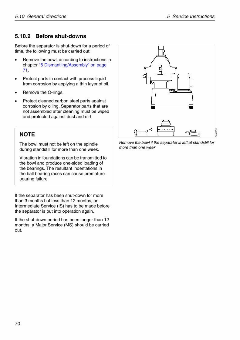
5.10.2 Before shut-downs
Before the separator is shut-down for a period of time, the following must be carried out:
Remove the bowl, according to instructions in chapter ‘‘6 Dismantling/Assembly” on page 71.
Protect parts in contact with process liquid from corrosion by applying a thin layer of oil.
Remove the O-rings.
Protect cleaned carbon steel parts against corrosion by oiling. Separator parts that are not assembled after cleaning must be wiped and protected against dust and dirt.
If the separator has been shut-down for more than 3 months but less than 12 months, an Intermediate Service (IS) has to be made before the separator is put into operation again.
If the shut-down period has been longer than 12 months, a Major Service (MS) should be carried out.
NOTE
The bowl must not be left on the spindle during standstill for more than one week.
Vibration in foundations can be transmitted to the bowl and produce one-sided loading of the bearings. The resultant indentations in the ball bearing races can cause premature bearing failure.
G04
6681
1
Remove the bowl if the separator is left at standstill for more than one week

71
6 Dismantling/Assembly
Contents
6.1 Inlet/outlet and bowl 73
6.1.1 Inlet/outlet and bowl dismantling 75
6.1.2 Inlet/outlet and bowl assembly 79
6.2 Bowl spindle and frame 87
6.2.1 Bowl spindle and framedismantling 87
6.2.2 Bowl spindle and frameassembly 92
6.3 Friction coupling 98
6.3.1 Friction coupling dismantling 99
6.3.2 Friction coupling assembly 101
6.4 Flat belt and tightener 104
6.4.1 Belt replacement and tightening 104
6.5 Oil filling device 109
6.5.1 Dismantling/assembly 109
6.6 Brake 110
6.6.1 Checking of friction element 111
6.7 Frame feet 112
6.7.1 Mounting of new frame feet 112
WARNING
Entrapment hazard
To avoid accidental start, switch off and lock power supply before starting any dismantling work.
G01
6573
1

6 Dismantling/Assembly
72
References to check-points
In the text you will find references to the Check point instructions in Chapter 5. The references appear in the text as in the following example:
✔ Check point‘‘5.3.7 Disc stack pressure” on page 56.
In this example, look up check point Disc stack pressure in Chapter 5 for further instructions.
Tools
Special tools from the tool kit must be used for dismantling and assembly. The special tools are specified in the Spare Parts Catalogue.
Additional tools needed for dismantling but not included in the tool kit are shown here.
For bowl and bowl spindle
1. Screw driver
2. Torque wrench (50 Nm) with socket 16 mm
3. Pliers for internal snap ring
4. Ball bearing puller
5. Screw vice with copper liners
6. Adjustable wrench, length approx. 400 mm
7. Adjustable wrench or spanner, width of jaws 24 mm
For friction coupling and flat belt
1. Pliers for internal snap ring
2. Pliers for external snap ring
3. T-handle, extension rod and socket 16 mm
4. Adjustable wrench or spanner, width of jaws 36 mm
5. Hammer
G02
7881
1
Two lifting slings, working load limit (WLL): >300 kgG
0578
621

73
6 Dismantling/Assembly 6.1 Inlet/outlet and bowl
6.1 Inlet/outlet and bowl
A Safety deviceB NutC Inlet housingD Outlet housingE Frame hood (incl. connecting housing)*F Lock ringG Gravity disc/clarifier discH Leader coneI Paring chamber cover
* The connecting housing is removed from the frame hood top at paring disc adjustment (Major Service).
Left-hand thread
Loctite 242/407
G01
6632
1
6.1 Inlet/outlet and bowl 6 Dismantling/Assembly
74
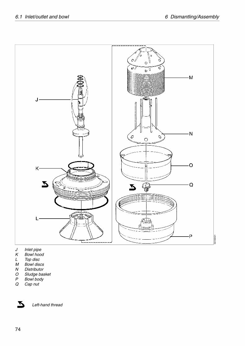
Left-hand thread
G01
6642
1
J Inlet pipeK Bowl hoodL Top discM Bowl discsN DistributorO Sludge basketP Bowl bodyQ Cap nut

75
6 Dismantling/Assembly 6.1 Inlet/outlet and bowl
6.1.1 Inlet/outlet and bowl dismantling
The frame hood and the heavy bowl parts must be lifted by means of a hoist. Position the hoist exactly above the bowl centre. Use an endless sling and a lifting hook with catch.
The parts must be handled carefully. Don’t place parts directly on the floor, but on a clean rubber mat, fibreboard or a suitable pallet.
1. Remove safety device (A) and look through the slot in the frame hood to see if the bowl still rotates.
The bowl parts can remain very hot for a considerable time after the bowl has come to a standstill.
2. Unscrew nut (B) clockwise and lift off inlet and outlet housings (C, D) together with the connecting hoses.
Left-hand thread!
WARNING
Entrapment hazards
Make sure that rotating parts have come to a complete standstill before starting anydismantling work.
G01
6651
1G
0166
611

6.1 Inlet/outlet and bowl 6 Dismantling/Assembly
76
3. Remove the four hooks and lift off frame hood (E).
4. Unscrew lock ring (F) clockwise by using the special tool; “Spanner for lock ring”.
Left-hand thread!
5. Lift off gravity disc/clarifier disc (G) and leader cone (H).
6. Carefully prise loose paring chamber cover (I) by using a screwdriver. Lift off the paring chamber cover.
NOTE
If the gravity disc has to be replaced owing to changed operating conditions, see ‘‘8.10.2 Gravity disc nomogram” on page 152.
G01
6671
1G
0166
811
S00
9611
1
G01
6691
1

77
6 Dismantling/Assembly 6.1 Inlet/outlet and bowl
7. Lift out inlet pipe (J) with the paring disc.
8. Preparations for unscrewing of bowl hood (K):
Fit the spanner to the bowl hood and secure it with the bolt (1).
Fit the compression tool and screw down the central screw until it stops (2).
Compress the disc stack by tightening the nut (3) firmly.
9. Unscrew bowl hood (K) clockwise by using a tin hammer.
Left-hand thread!
NOTEUse the compression tool as instructed.Use of substitute tools can damage the equipment.
G01
6701
1G
0167
111
S00
9651
1S
0098
411
G01
6722
1

6.1 Inlet/outlet and bowl 6 Dismantling/Assembly
78
10. Lift off the bowl hood with the spanner still attached.
11. Lift out top disc (L), bowl discs (M) and distributor (N).
12. Remove the disc stack from the compression tool.
Screw the nut of the compression tool up against the central screw eye bolt, turn the unit with the tool still attached upside down and hit it against a firm base. This will facilitate loosening of the top disc.
13. Lift out the sludge basket (O).
14. Unscrew cap nut (Q).
Left-hand thread!
G01
6731
1G
0601
811
G06
0171
1G
0167
511

79
6 Dismantling/Assembly 6.1 Inlet/outlet and bowl
15. Lift out bowl body (P) using the special tool.
Ease the bowl body off with the central screw of the tool. If necessary, knock on the handle.
Soak and clean all parts thoroughly in suitable cleaning agent, see ‘‘5.7.1 Cleaning agents” on page 62.
Remove O-rings and replace them with spares from the intermediate service kit (IS).
✔ Check points‘‘5.3.1 Corrosion” on page 48,‘‘5.3.2 Erosion” on page 50,‘‘5.3.3 Cracks” on page 51.
6.1.2 Inlet/outlet and bowl assembly
Make sure that the following check points are carried out before and during assembly of the separator bowl.
Bowl spindle cone and bowl body nave.
Threads on bowl hood and bowl body.
Disc stack pressure.
Inlet pipe and paring disc.
Paring disc height adjustment (normally only at Major Service).
G01
6761
1
S00
9621
1

6.1 Inlet/outlet and bowl 6 Dismantling/Assembly
80
J Inlet pipeK Bowl hoodL Top discM Bowl discs
N DistributorO Sludge basketP Bowl bodyQ Cap nut
Left-hand threadMolykote 1000 Paste (thin layer to be rubbed into surface)
Silicone grease (thin layer)
G01
6952
1

81
6 Dismantling/Assembly 6.1 Inlet/outlet and bowl
A Safety deviceB NutC Inlet housingD Outlet housingE Frame hood (incl. connecting housing)F Lock ringG Gravity disc/clarifier discH Leader coneI Paring chamber cover
Left-hand thread
Loctite 242/407
Silicone grease (thin layer)
Molykote 1000 Paste (thin layer to be rubbed into surface)
NOTEBe sure bowl parts are not interchanged.Out of balance vibration will reduce ball bearing life.
G01
6962
1

6.1 Inlet/outlet and bowl 6 Dismantling/Assembly
82
1. Wipe clean the spindle top and nave bore in bowl body (P). Apply oil to the tapered end of the spindle, smear the oil over the surface and wipe off surplus with a clean cloth.
✔ Check point‘‘5.3.5 Spindle top cone and bowl body nave” on page 53.
2. Fit the bowl body on the spindle. Avoid damaging the spindle cone.
a. Attach the special “Lifting tool” to the bowl body nave.
b. Screw down the central screw of the tool, then lower the bowl body until the screw rests on the spindle top.
c. Screw up the central screw and the bowl body will sink down on the spindle cone.
3. Screw cap nut (Q) counter-clockwise onto the spindle. Tighten firmly.
Left-hand thread!
✔ Check pointBefore assembling the bowl discs, check the threads of the bowl hood and bowl body, see ‘‘5.3.6 Threads on bowl hood and bowl body” on page 54.
G01
6972
1G
0169
811
S00
9621
1
G01
6991
1

83
6 Dismantling/Assembly 6.1 Inlet/outlet and bowl
4. Assemble bowl discs (M) with top disc (L) and distributor (N). Make sure that the pins in the distributor fit properly into the holes of the top disc.
5. Fit the “Compression tool” and screw down the central screw until it stops.
Compress the disc stack by tightening the nut firmly.
6. Fit the disc stack assembly in the bowl body. Make sure that the cuts in the wings on the underside of the distributor fit properly in the corresponding lugs of the bowl.
Oil
NOTEUse the compression tool as instructed.Use of substitute tools can damage the equipment.
G01
7001
1
S00
9841
1
G01
7011
1

6.1 Inlet/outlet and bowl 6 Dismantling/Assembly
84
7. Fit the special “Spanner for the bowl hood” to the bowl hood (K) and tighten the securing bolt.
Install the bowl hood:
Apply a thin layer of Molykote Paste 1000 to the threads and on contact and locating surfaces. Do not forget the ribs on top disc.
Screw on the bowl hood by hand.
Left-hand thread!
✔ Check point‘‘5.3.7 Disc stack pressure” on page 56.
8. Tighten the bowl hood by using a tin hammer.
Strike the spanner handle until bowl hood lies tightly against bowl body. In a new bowl, the assembly marks now will be in line with each other.
✔ Check point‘‘5.3.6 Threads on bowl hood and bowl body” on page 54.
WARNING
Disintegration hazard
The assembly mark on the bowl hood must never pass the mark on the bowl body by more than 25°.
G01
7022
1
S00
9651
1
G01
7031
1

85
6 Dismantling/Assembly 6.1 Inlet/outlet and bowl
9. Place inlet pipe (J) in the bowl.
✔ Check point‘‘5.3.4 Threads of inlet pipe, paring disc” on page 52.
10. Fit paring chamber cover (I) by pressing it down gently.
11. Assemble leader cone (H) and gravity disc/clarifier disc (G).
12. Fit lock ring (F).
Apply a thin layer of Molykote Paste 1000 to the threads and on contact and locating surfaces.
Left-hand thread!
Molykote 1000 Paste (thin layer to be rubbed into surface)
G01
6701
1G
0173
411
G01
7351
1
S00
9611
1

6.1 Inlet/outlet and bowl 6 Dismantling/Assembly
86
13. Fit frame hood (E).
In case of Major Service remove the connecting housing and fit a new O-ring on the insert (2).
✔ Check point‘‘5.4.1 Paring disc height adjustment” on page 57. To be performed at Major Service and if the bowl spindle has been dismantled.
14. Fit inlet/outlet housing (C and D).
Tighten nut (B).
Left-hand thread!
Then rotate the bowl by means of the flat belt.
If the bowl does not rotate freely or a scraping noise is heard, incorrect bowl assembly or incorrect height adjustment of the paring disc can be the cause.
15. Fit the cover on the frame bottom part if it has been removed.
16. Make sure that the gasket on the safety device is in position. If not, glue with Loctite 407.
Fit and secure safety device (A).
17. Fit the connecting hoses if they have been removed. Make sure to fit their gasket rings.
NOTETo avoid damage on the inlet pipe the tightening torque must not exceed 30 Nm.
G00
7294
1
1. Connecting housing2. Insert3. Height adjusting ring(s)
G01
7042
1G
0170
511

87
6 Dismantling/Assembly 6.2 Bowl spindle and frame
6.2 Bowl spindle andframe
6.2.1 Bowl spindle and frame dismantling
Before dismantling the bowl spindle, the inlet and outlet housing, frame hood and bowl as well as the flat belt must be removed.
Before dismantling, in the case of Major Service, or if the separator vibrates while running, see
✔ Check point‘‘5.4.2 Radial wobble of bowl spindle” on page 58.
A Seal ringAA Frame top partB Deflector ring/O-ringC Top bearing coverD GasketE FanF Buffer holderG Rubber buffersH Bowl spindleHA Flat keyI Ball bearing holderJ Ball bearingK Snap ringL Ball bearingM Oil pumpN Belt pulleyO O-ringP Frame, intermediate partQ O-ringR Nut
MS Parts to be renewed at Major Service
G01
6773
1

6.2 Bowl spindle and frame 6 Dismantling/Assembly
88
1. Loosen but do not remove the motor adapter screws. Remove the cover from the frame bottom part. Remove the flat belt.
2. Remove the screws and lift off frame top part (AA). Lip seal ring (A) must removed in the case of Major Service, or if found damaged.
3. Clean the bowl spindle cone in place and remove deflector ring (B).
G01
6781
2G
0167
921
G01
6802
1

89
6 Dismantling/Assembly 6.2 Bowl spindle and frame
4. Remove, in the following sequence:
Top bearing cover (C)
Gasket (D)
Fan (E)
Buffer holder (F)
Rubber buffer (G)
5. Screw the cap nut (left-hand thread) onto the spindle top to protect the top and bore.
Lift out spindle assembly (H), rubber buffer (G) and O-ring (O).
Remove snap ring (K) by using a pair of pliers and pull off ball bearing holder (I).
NOTEBe very careful not to damage the wings of the buffer holder.
G01
6811
1G
0168
231

6.2 Bowl spindle and frame 6 Dismantling/Assembly
90
6. Clamp the bowl spindle (H) in a screw vice. Remove the nut (R) and lift off the belt pulley (N). If the pulley has stuck, lubricate and fit the special “Mounting and dismantling tool” (1).
Use a long spanner (450-650 mm) to press belt pulley (N) off the spindle (H).
Remove oil pump (M) by hand, do not loos the flat key.
7. Pull off ball bearing (L) using a puller and thrust washer. Pull off bearing (j) using the “driving off tool” and a hammer.
Molykote 1000 Paste (thin layer to be rubbed into surface)
Oil
NOTEAlways discard a used bearing.
G00
7626
1
S00
9641
1
G01
6841
1
S00
9371
1

91
6 Dismantling/Assembly 6.2 Bowl spindle and frame
8. Every 3 years, lift off frame intermediate part (P) and fit a new O-ring (Q). This O-ring is not included in any service kit, but must be ordered separately.
9. Clean the oil sump.
10. Clean all dismantled parts thoroughly in a degreasing agent and check for damage and corrosion.
Replace all parts supplied in the spare parts kits.
G01
6851
1

6.2 Bowl spindle and frame 6 Dismantling/Assembly
92
6.2.2 Bowl spindle and frame assembly
A Seal ringAA Frame top partB Deflector ring/O-ringC Top bearing coverD GasketE FanF Buffer holderG Rubber buffersH Bowl spindleHA Flat keyI Ball bearing holderJ Ball bearingK Snap ringL Ball bearingM Oil pumpN Belt pulleyO O-ringP Frame, intermediate partQ O-ringR Nut
MS Parts to be renewed at Major Service
Loctite 242
Silicone grease (thin layer)
Molykote 1000 Paste (thin layer to be rubbed into surface)
G01
6863
1

93
6 Dismantling/Assembly 6.2 Bowl spindle and frame
1. Assemble the frame intermediate part (P). Fit a new O-ring (Q). (To be done at each 3-year service).
Use a torque wrench and tighten the screws lightly crosswise at first. Then tighten all around to 45 Nm.
Secure the screws with Loctite 242.
2. Inspect the tapered end of the bowl spindle.
Assemble ball bearings (J and L).
Heat the new ball bearings in oil to maximum 125 °C. Use the special “Mounting tool” from the tool kit.
Loctite 242
NOTEAlways fit new bearings.
If in doubt how to install roller bearings in a correct way, please see the detailed description in ‘‘5.10.1 Ball and roller bearings” on page 67.
G01
6871
1G
0168
821
S00
9371
1

6.2 Bowl spindle and frame 6 Dismantling/Assembly
94
3. Fit oil pump (M) and belt pulley (N), do not forget the flat key. Make sure that the recess in the belt pulley fits over the guide pin in the oil pump.
4. Fit the nut and tighten it.
G01
1395
1G
0114
351

95
6 Dismantling/Assembly 6.2 Bowl spindle and frame
5. Fit ball bearing holder (I) and secure it with snap ring (K).
Fit O-ring (O) and rubber buffer (G).
Lower spindle assembly (H) carefully into the separator intermediate frame.
6. Assemble, in the following sequence:
Rubber buffer (G)
Buffer holder (F)
Fan (E)
Gasket (D)
Top bearing cover (C)
Make sure that the mm hole in fan (E) is clean and the lugs in the fan enter the recesses in the bowl spindle.
Before tightening, make sure that there is some play (X) between top bearing cover (C) and the frame. The play will disappear when the screws are tightened.
Tighten the screws sequentially (not crosswise) in order to successively compress the rubber buffers.
G01
6822
1G
0169
121

6.2 Bowl spindle and frame 6 Dismantling/Assembly
96
7. Push down deflector ring (B) till it stops.
8. Assemble frame top part (AA). If lip seal ring (A) has been removed, fit a new one beforethe frame top part is put in place.
Make sure the lip seal is turned the correct way. See illustration.
Silicone grease (thin layer)
G01
6921
1G
0206
731
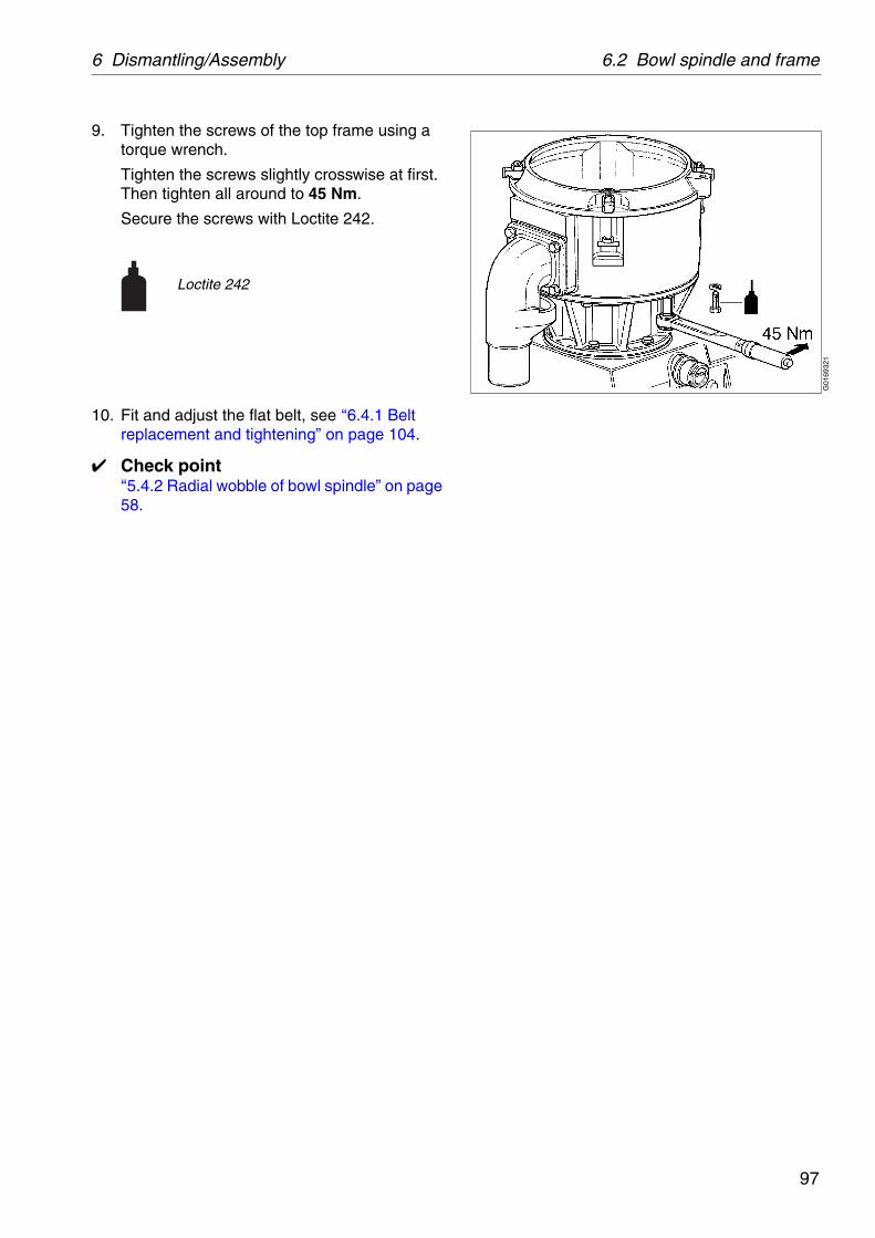
97
6 Dismantling/Assembly 6.2 Bowl spindle and frame
9. Tighten the screws of the top frame using a torque wrench.
Tighten the screws slightly crosswise at first. Then tighten all around to 45 Nm.
Secure the screws with Loctite 242.
10. Fit and adjust the flat belt, see ‘‘6.4.1 Belt replacement and tightening” on page 104.
✔ Check point‘‘5.4.2 Radial wobble of bowl spindle” on page 58.
Loctite 242
G01
6932
1

6.3 Friction coupling 6 Dismantling/Assembly
98
6.3 Friction couplingIf the separator does not attain full speed within about 2,5 minutes, the friction elements or the coupling may be worn or greasy. The friction elements must then be replaced with new ones or be thoroughly cleaned from grease.
WARNING
Entrapment hazards
Make sure that rotating parts have come to a complete standstill before starting anydismantling work.
G01
7063
1
A Snap ringB Snap ringC Ball bearingsD WasherE Belt pulleyF Coupling hubG Friction elementH CoverI Snap ring
(MS) =Set of friction elements included in the Major Service Kit

99
6 Dismantling/Assembly 6.3 Friction coupling
6.3.1 Friction coupling dismantling
1. Check that the belt tightener is in backward position.
2. Remove the motor adapter screws.
3. Remove the side cover from the frame bottom part.
4. Loosen but do not remove the two screws securing the brake.
5. Remove the flat belt.
6. Remove the electric motor complete with the friction coupling and motor adapter.
Weight of motor including adapter and friction coupling is not more than 20 kg.
7. Remove snap ring (I), cover (H) and friction elements (G).
If the friction elements are worn, fit new ones. Replace all friction elements even if only one is worn.
If the friction elements are only greasy:Clean the friction elements and the inside of belt pulley (E) with a degreasing agent.
G01
6782
1G
0077
331
G01
7082
1

6.3 Friction coupling 6 Dismantling/Assembly
100
8. Remove the screw, spring washer and washer from the friction coupling.
Complete dismantling of the friction coupling
9. Lubricate and fit the special “Mounting and dismantling tool”.
Ease off the coupling.
10. Remove snap rings (A and B) and drive off coupling hub (F). Turn the coupling, i.e. belt pulley (E) with bearings (C), the other way round and drive off the ball bearings and washer, using a tube.
11. Clean all parts in a degreasing agent and replace parts supplied in the spare parts kits.
Molykote 1000 Paste(thin layer to be rubbed into surface)
Oil
NOTEAlways discard a used bearing.
G01
7091
1G
0171
021
S00
9641
1
G01
7112
1

101
6 Dismantling/Assembly 6.3 Friction coupling
6.3.2 Friction coupling assembly
Before the friction coupling is assembled, examine all parts thoroughly for wear and corrosion.
1. Assemble the new ball bearings in belt pulley (E) by using a tube and a hammer.
Apply Loctite 641 on the outer surfaces of ball bearings (C).
Knock down the bearings carefully (do not forget washer D) by using the tube which must rest on the outer race of the bearing.
The new bearings must not be heated as they are packed with grease and sealed with plastic membranes.
After the assembly of the bearings, fit snap ring (B).
2. Apply Loctite 641 on the coupling hub (F) and knock it down into the belt pulley by using a hammer.
3. Fit snap ring (A).
Loctite 641
NOTEDo not refit used bearings.
Loctite 641G
0171
241
G01
7133
1

6.3 Friction coupling 6 Dismantling/Assembly
102
4. Wipe clean the motor shaft and apply a thin oil film on it. Fit the special “Mounting and dismantling tool” to the motor shaft (by means of the small screw on one end of the tool) and press the friction coupling onto the shaft.
5. Fit the screw with the washer and spring washer to secure the friction coupling.
Assembly of friction elements
6. Fit new friction elements (G), cover (H) and snap ring (I).
A coupling with two friction elements (G) is used for 60 Hz installations.
A coupling with four friction elements (G) is used for 50 Hz installations.
Molykote 1000 Paste(thin layer to be rubbed into surface)
Oil
G01
7102
1
S00
9641
1
G01
7091
1G
0170
811

103
6 Dismantling/Assembly 6.3 Friction coupling
7. Degrease and clean the contact surfaces of frame and motor adapter. Lubricate the contact surfaces with Molykote 1000 paste. Then fit the electric motor with adapter and friction coupling in position.
Also lubricate the threads of the belt tightener with Molykote 1000 paste or similar.
8. Fit and tighten the flat belt, see ‘‘6.4.1 Belt replacement and tightening” on page 104.
9. Tighten the brake screws and fit the side cover.
Molykote 1000 Paste(thin layer to be rubbed into surface)
NOTEThe belt must be re-tightened before starting the separator, see next page.
G00
7734
1G
0167
812
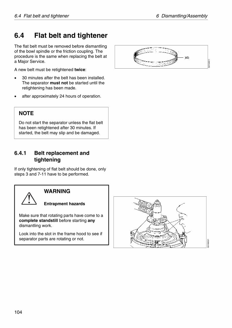
6.4 Flat belt and tightener 6 Dismantling/Assembly
104
6.4 Flat belt and tightenerThe flat belt must be removed before dismantling of the bowl spindle or the friction coupling. The procedure is the same when replacing the belt at a Major Service.
A new belt must be retightened twice:
30 minutes after the belt has been installed. The separator must not be started until the retightening has been made.
after approximately 24 hours of operation.
6.4.1 Belt replacement and tightening
If only tightening of flat belt should be done, only steps 3 and 7-11 have to be performed.
NOTE
Do not start the separator unless the flat belt has been retightened after 30 minutes. If started, the belt may slip and be damaged.
WARNING
Entrapment hazards
Make sure that rotating parts have come to a complete standstill before starting anydismantling work.
Look into the slot in the frame hood to see if separator parts are rotating or not.
G01
5461
1G
0166
521

105
6 Dismantling/Assembly 6.4 Flat belt and tightener
1. Remove the cover and the brake handle.
2. Check that the belt tightener is in backward position.
3. Loosen the motor adapter screws.
Knock out the tubular spring pin and separate the parts, lubricate and assemble the parts.
NOTE
Pay attention to the air gap “A” between the cup springs and the threaded sleeve. The distance “A” must not exceed 0,5 mm. Otherwise a correct belt tightening will be impossible.
NOTE
To guarantee a proper function of the belt tightener it is advisable to protect the surfaces
Molykote 1000 Paste
G01
7161
1G
0473
911
G00
7662
2G0885711

6.4 Flat belt and tightener 6 Dismantling/Assembly
106
4. Remove the existing belt and clean the raceways of the bowl spindle and the friction coupling by using a degreasing agent. Wipe the raceways with a clean rag after cleaning.
Exercise the greatest possible cleanliness. There must be no dirt, oil or grease on the raceways.
5. Remove the motor adapter screws. Lift the motor together with adapter and friction coupling and check that there is a sufficient film of Molykote 1000 Paste, or an equivalent lubricating paste, between the adapter and the frame surface. Lower the motor after checking. Fit the motor adapter screws but do not tighten them.
The weight of motor including adapter and friction coupling is not more than 20 kg.
The threads of the belt tightener should be lubricated with Molykote 1000 Paste or similar.
6. Fit a new belt. Start on the motor side. Tighten the belt by moving the motor backwards by hand. Pull the belt around a few turns by hand.
Molykote 1000 Paste(thin layer to be rubbed into surface)
G01
7152
1G
0077
341
G01
7165
1

107
6 Dismantling/Assembly 6.4 Flat belt and tightener
7. Rotate the belt tightener by rotating the shaft until it makes contact with the frame pad.
8. Tighten the shaft (1) further until the threaded sleeve (2) and dog (3) are disengaged. “Shake” the motor by hand several times during this operation in order to overcome the friction between the motor adapter and the frame.
9. Tighten the motor adapter screws.
10. Loosen the belt tightener by rotating the threaded sleeve (2) backwards.
G04
8982
1G
0477
111
G00
7662
2G
0477
211

6.4 Flat belt and tightener 6 Dismantling/Assembly
108
11. Rotate the shaft (1) relative to the threaded sleeve (2) until the threaded sleeve (2) and dog (3) are engaged again with a clicking sound.
.
12. Let the belt stay in this position for at least 30 minutes without starting the separator.
Then repeat steps 3 and 7-11 above. After this proceed to step 13.
13. Fit the cover and the brake handle.
14. The separator may now be started.
Repeat steps 3 and 7-11.
NOTE
If the springs (4) are not decompressed they will loose their tension and correct tightening of belt will be impossible.
NOTE
Do not start the separator unless the flat belt has been retightened after 30 minutes. If started, the belt may slip and be damaged.
NOTE
The belt must be retightened when the separator has been in operation approximately 24 hours after the belt change.
G04
7731
1G
0474
011
G01
7164
1

109
6 Dismantling/Assembly 6.5 Oil filling device
6.5 Oil filling device
6.5.1 Dismantling/assembly
Drain off the oil, see ‘‘5.8 Oil change” on page 64.
Unscrew nipple (4) and pull off the oil filling device. Then unbend the round safety wire (6) and pull off the nipple (4).
1. If plate (8) is to be replaced, wipe the sight glass (7) with a degreasing agent.
2. Fit the new plate on the outside of the sight glass. The plate is self-adhesive.
3. Mark the position of the plate relative to the recess in sleeve (1).
Assemble the oil filling device and fit it into the frame. Note that the mark on sleeve (1) must be positioned opposite the mark on the frame. Fill the sump with new oil.
Silicone grease (thin layer)
1 Sleeve for oil filling2 O-ring3 O-ring4 Nipple
5 Sealing ring6 Round safety wire7 Sight glass8 Plate
G01
5581
1
G01
5591
1
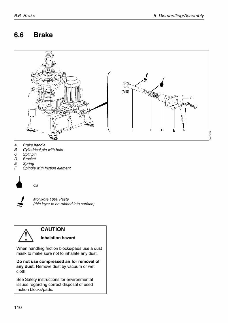
6.6 Brake 6 Dismantling/Assembly
110
6.6 Brake
CAUTION
Inhalation hazard
When handling friction blocks/pads use a dust mask to make sure not to inhalate any dust.
Do not use compressed air for removal of any dust. Remove dust by vacuum or wet cloth.
See Safety instructions for environmental issues regarding correct disposal of used friction blocks/pads.
G01
7172
1
A Brake handleB Cylindrical pin with holeC Split pinD BracketE SpringF Spindle with friction element
Oil
Molykote 1000 Paste (thin layer to be rubbed into surface)

111
6 Dismantling/Assembly 6.6 Brake
6.6.1 Checking of friction element
A worn or oily friction element will lengthen the stopping time. Remove bracket (D) with the brake. Examine the friction element.
If the friction element is worn; Fit a new complete spindle (F) (includes friction element).
If the friction element is oily; Clean the element and its surface in contact with the belt pulley with a suitable degreasing agent.
Checking of bracket (D), spindle (F) and spring (E)
Rust can form on the brake parts and cause the brake to jam.
Remove rust from the spindle and the corresponding guide surface on the bracket. Rub the surface of the spindle with lubricating paste. Replace the spring with a new one if it has lost its stiffness. Oil the spring when assembling.
Checking the brake
After the brake assembly has been fitted, release the brake and rotate the bowl slowly by hand. If a scraping noise is heard, the friction element is probably touching the coupling pulley surface (A). If so, it is necessary to adjust the position of the motor adapter and retighten the flat belt, see ‘‘6.4 Flat belt and tightener” on page 104.
Molykote 1000 Paste (thin layer to be rubbed into surface)
G01
7181
1G
0171
921

6.7 Frame feet 6 Dismantling/Assembly
112
6.7 Frame feet
6.7.1 Mounting of new frame feet
When replacing the frame feet, the separator must be lifted.
Remove the bowl before lifting the separator.
Follow ‘‘5.6 Lifting instructions” on page 59.
1. Loosen the foundation bolts and lift the separator.
2. Remove the existing frame feet.
3. Mount the new feet.
4. Place the separator in its original position and fasten the foundation bolts.
5. Remove the two eye bolts.
6. Assemble the separator bowl, see ‘‘6.1.2 Inlet/outlet and bowl - assembly” on page 79. G
0613
411

113
7 Trouble-tracing
Contents
7.1 Trouble-tracing procedure 114
7.2 MMB mechanical function 115
7.2.1 The separator does not start 115
7.2.2 Start-up time too long 115
7.2.3 Starting power too low 115
7.2.4 Starting power too high 115
7.2.5 Separator vibrates duringstarting sequence 116
7.2.6 Separator vibrates duringnormal running 117
7.2.7 Smell 117
7.2.8 Noise 117
7.2.9 Speed too high 118
7.2.10 Speed too low 118
7.2.11 Stopping time too long 118
7.2.12 Water in oil sump 118
7.2.13 Liquid flows through bowlcasing drain 119
7.3 Purification faults 120
7.3.1 Unsatisfactory separationresult 120
7.3.2 Outgoing water contains oil 120
7.3.3 Oil discharge through wateroutlet = broken water seal 121
7.4 Clarification faults 122
7.4.1 Unsatisfactoryseparation result 122
7.4.2 Oil discharge throughwater outlet 122
Study theSystem Manual’sTrouble-tracing
chapter first.(if applicable)
If the problem is not solved in the System Manual’s
Trouble-tracing, continue with this chapter.
Trouble-tracing

7.1 Trouble-tracing procedure 7 Trouble-tracing
114
7.1 Trouble-tracing procedure
This chapter applies to trouble-tracing concerning functions of the separator only. It does not include the other equipment in your processing system.
Always start with trouble-tracing instructions in the System Manual, and if required, continue with the instructions below. If the problem still is not solved, contact your Alfa Laval representative.

115
7 Trouble-tracing 7.2 MMB mechanical function
7.2 MMB mechanical function
7.2.1 The separator does not start
7.2.2 Start-up time too long
7.2.3 Starting power too low
7.2.4 Starting power too high
Possible cause Action
No power supply to motor Check power supply.
Possible cause Action
Brake applied. Release.
Friction elements worn or oily. Fit new friction elements or clean the old ones if they are oily.
Belt tension too loose. Tighten the belt.
Motor failure. Repair.
Incorrect power supply (50 Hz instead of 60 Hz).
Bearings damaged or worn.
Use applicable 60 Hz power supply.
Install new bearings.
Possible cause Action
Motor failure. Repair the motor.
Possible cause Action
Motor failure. Repair the motor.
Brake applied Release the brake.
50 Hz pulley running on 60 Hz power supply.
After immediate stop, install correct pulley.

7.2 MMB mechanical function 7 Trouble-tracing
116
7.2.5 Separator vibrates duringstarting sequence
NOTE
Some vibration is normal during starting sequence when the separator passes through its critical speeds.
Possible cause Action
Bowl out of balance due to: After emergency stop, identify and rectify cause.
poor cleaning
incorrect assembly
too few discs
insufficiently tightened bowl hood.
bowl assembled with parts from other separators.
Incorrectly tightened bowl hood involves fatal danger.
Height adjustment of paring disc is incorrect.
Check and adjust.
Vibration dampers in frame feet worn out. Fit new frame feet.
Bowl spindle bent (max. 0,04 mm). Fit a new bowl spindle.
Top and/or bottom bearing damaged or worn.
Fit new bearings.
Spindle top bearing rubber buffer defective.
Fit new rubber buffer.

117
7 Trouble-tracing 7.2 MMB mechanical function
7.2.6 Separator vibrates duringnormal running
7.2.7 Smell
7.2.8 Noise
Possible cause Action
Uneven sludge deposits in sludge space. Clean the bowl.
Bearings damaged or worn. Fit new bearings.
Vibration-dampers in frame feet worn out. Fit new frame feet.
Spindle top bearing rubber buffer defective.
Fit new rubber buffer.
Possible cause Action
Normal occurrence during start as the friction elements slip.
None.
Belt slips. Tighten the belt. Check for oily pulleys.
Brake is applied. Release the brake.
Top and/or bottom bearing overheated. Fit new bearings.
Possible cause Action
Oil level in oil sump is too low. Read oil level and add oil if necessary.
Height adjustment of paring disc is incorrect.
Check and adjust.
Top and/or bottom bearing damaged or worn.
Fit new bearings.

7.2 MMB mechanical function 7 Trouble-tracing
118
7.2.9 Speed too high
7.2.10 Speed too low
7.2.11 Stopping time too long
7.2.12 Water in oil sump
Possible cause Action
Incorrect transmission (50 Hz pulley running on 60 Hz power supply).
After immediate stop, install correct transmission.
Frequency of power supply (50/60 Hz). Check.
Possible cause Action
Brake is applied. Release the brake.
Friction elements worn or oily. Fit new friction elements or clean the old ones if they are oily.
Belt tension too loose. Tighten the belt.
Motor failure/motor bearings. Repair the motor.
Top/bottom bearings damaged or worn. Fit new bearings.
Bearing overheated/damaged. Fit new bearings.
Incorrect transmission (60 Hz pulley running on 50 Hz current).
Make sure that the pulley is intended for 50 Hz power supply.
Possible cause Action
Brake worn or oily. Fit a new brake or clean if oily.
Possible cause Action
Bowl casing drain obstructed. Clean. Change oil in oil sump.
Leakage at top bearing. Fit a new seal ring and change oil in oil sump.
Condensation. Clean the oil sump. Change oil in oil sump.

119
7 Trouble-tracing 7.2 MMB mechanical function
7.2.13 Liquid flows through bowlcasing drain
Possible cause Action
High water content in oil. None (normal).
Broken water seal.
The supply of displacement/sealing water is not sufficient due to clogged strainer, kinked hose or low water pressure.
See 7.3.3.
Straighten the hose or clean the strainer. Check the water flow.
Seal ring on gravity disc/clarifier disc defective.
Fit a new seal ring.
Bowl hood seal ring defective. Fit a new seal ring.
Seal rings in paring disc device defective. Fit new seal rings.
Bowl speed too low. Make sure current is on and brake is off. Retighten the flat belt or inspect motor and power transmission.

7.3 Purification faults 7 Trouble-tracing
120
7.3 Purification faults
7.3.1 Unsatisfactory separationresult
7.3.2 Outgoing water contains oil
Possible cause Action
Gravity disc hole too small.
Incorrect separating temperature.
Throughput too high.
Use a gravity disc with a larger hole.
Adjust temperature.
Reduce throughput.
Sludge space in bowl is filled. Empty the sludge basket in the bowl.
Disc stack clogged. Clean the bowl discs.
Inlet clogged. Clean.
Bowl speed too low. See ‘‘7.2.10 Speed too low” on page 118.
Possible cause Action
Gravity disc hole too large. Use a gravity disc with a smaller hole.
Seal ring under the gravity disc defective. Fit a new seal ring.

121
7 Trouble-tracing 7.3 Purification faults
7.3.3 Oil discharge through water outlet = broken water seal
Possible cause Action
Gravity disc too large. Use a gravity disc with a smaller hole.
Separation temperature too low. Increase temperature.
Throughput too high. Reduce throughput.
Valve(s) in oil outlet line closed. Open the valve(s) and adjust back pressure to normal value.
Sealing water volume too small. Supply more water.
Seal ring under gravity disc defective. Fit a new seal ring.
Disc stack clogged. Clean the bowl discs.
Bowl speed too low. See ‘‘7.2.10 Speed too low” on page 118.
Bowl incorrectly assembled. Examine and make correct.

7.4 Clarification faults 7 Trouble-tracing
122
7.4 Clarification faults
7.4.1 Unsatisfactory separation result
7.4.2 Oil discharge through water outlet
Possible cause Action
Separating temperature too low. Adjust.
Throughput too high. Reduce throughput.
Feed oil contains water. Re-assemble and operate the separator as a purifier.
Disc stack clogged. Clean the bowl discs.
Sludge space in bowl filled. Empty the sludge basket.
Bowl speed too low. See ‘‘7.2.10 Speed too low” on page 118.
Possible cause Action
Valve(s) in outlet line closed. Open the valve(s) and adjust to normal back pressure.
Disc stack clogged. Clean the bowl discs.
Seal ring under gravity disc is defective. Fit a new seal ring.
Bowl incorrectly assembled. Examine and make correct.

123
8 Technical Reference
Contents
8.1 Product description 124
8.2 Technical data 125
8.3 Basic size drawing 126
8.3.1 Dimensions of connections 127
8.4 Connection list 128
8.5 Interface description 129
8.5.1 General 129
8.5.2 Definitions 129
8.5.3 Component descriptionand signal processing 130
8.5.4 Function graph and runninglimitations 131
8.6 Quality specification,operating water 132
8.7 Lubricants 133
8.7.1 Lubrication chart 133
8.7.2 Lubricants 136
8.7.3 Recommended lubricating oils 140
8.7.4 Recommended oil brands (04) 141
8.7.5 Recommended oil brands (08) 143
8.8 Drawings 145
8.8.1 Foundation plan 145
8.9 Electric motor 146
8.10 Electric motor(Crompton Greaves) 148
8.10.1 Machine plates andsafety labels 150
8.10.2 Gravity disc nomogram 152
8.11 Storage and installation 153
8.11.1 Storage and transport
of goods 153
8.11.2 Planning of installation 156
8.11.3 Foundations 157

8.1 Product description 8 Technical Reference
124
8.1 Product descriptionAlfa Laval ref. 563227, rev. 2
Units according to ISO Standard.
The manufacturer reserves the right to change specifications without notice.
Product number: 881152-01-03 /2
Separator type: MMB 305S-11
Application: Mineral Oil
Technical design: Purifier (clarifier as option) with solid-wall bowl
Machine bottom part for belt drive.
Intended for marine- and land applications.
Sealings available in Nitrile.
Designed in according with standards:
89/392 EEC
91/368 EEC
93/44 EEC
The Council Directive of the European Communities. (CE-marking is possible if manual is included in the delivery.)
EN 292-2 Safety of machines. Use of the machine in applications subject to hygienic demands requires a well-adapted cleaning program.
Restrictions: Ambient temperature: +5 °C to +55 °C.
Feed temperature: 0 °C to +100 °C.
Not to be used for liquids with flashpoint below 60 °C .
Risk for corrosion and erosion has to be investigated in each case by application centre.
Further restrictions and instructions are found in set of complementary documents and technical data.

125
8 Technical Reference 8.2 Technical data
8.2 Technical dataAlfa Laval ref. 556411, rev. 2
.
Units according to ISO Standard.
The manufacturer reserves the right to change specifications without notice.
Bowl speed max.: 9510/ 9510 rev/min. 50Hz/60Hz
Speed motor shaft max: 3000/3600 rev/min. 50Hz/60Hz
Gear ratio: 130:41/106:4150
Hz
Hydraulic capacity: 6 m³/h
Max. density of sediment/feed: 1600/1100 kg/m³
Feed temperature: 0/100 min./max. ×C
Weight of separator: 179 kg (without motor)
Motor power: 3 kW
Jp reduced to motor shaft: 10,1 kg/m² 50Hz
Jp reduced to motor shaft: 7 kg/m² 60Hz
Power consumption: 0,7/ 2,3 kW(idling/ at max. capacity)
Max. power consumption: 4,3 kW (at starting up)
Starting time: 2 / 2,5 minutes (min./ max.)
Stopping time with brake: 3 / 4 minutes (min./ max.)
Stopping time without brake: 18 minutes (average)
Lubricating oil volume: 0,5 liters
Max. running time,
empty bowl: 480 minutes
filled bowl: 480 minutes
Sound power/ sound press. level. 8,9/ 74 Bel(A)/ dB(A)
Max vibration level, separator in use: 9 mm/sec (r.m.s)
Bowl max. inner diameter 217 mm
Bowl volume 3,6 liters
Bowl weight 32 kg
Bowl body material AL 111 2377-02
There are other material than stainless steel in contact with process liquid.

8.3 Basic size drawing 8 Technical Reference
126
8.3 Basic size drawingAlfa Laval ref. 557416, rev. 0
Connections 201 and 220 are turnable
Vertical force not exceeding 5 kN/foot
Horizontal force not exceeding 7 kN/foot
G06
0661
1

127
8 Technical Reference 8.3 Basic size drawing
8.3.1 Dimensions of connectionsAlfa Laval ref. 557416, rev. 0
Data for connections,see‘‘8.4 Connection list” on page 128
All connections to be installed non-loaded and flexible
G06
0671
1

8.4 Connection list 8 Technical Reference
128
8.4 Connection listAlfa Laval ref. 557433, rev. 0
‘‘8.3 Basic size drawing” on page 126, and ‘‘8.3.1 Dimensions of connections” on page 127.
Connection No. Description Requirements/limit
201 Inlet for process liquid
Permitted temperatures Min. 0 °C, Max. +100 °C
206 Inlet for liquid seal and displacement liquid Fresh water
Liquid seal water flow 5,5 ±0,6 litres/minute
Liquid seal water period 30 seconds
220 Outlet for light phase (oil)
Pressure Max. 280 kPa
221 Outlet for heavy phase (water) No counterpressure
701 Motor for separator
Deviation from nominal frequency Max. ±5%

129
8 Technical Reference 8.5 Interface description
8.5 Interface descriptionAlfa Laval ref. 557260, rev. 1
8.5.1 General
In addition to the Connection List this document describes limitations and conditions for safe control, monitoring and reliable operation.
At the end of the document a function graph and running limitations are found.
8.5.2 Definitions
Stand still (Ready for start) means:
The machine is assembled correctly.
All connections are installed according to Connection List, Interconnection Diagram and Interface Description.
Start means:
The power to the separator is on.
The acceleration is supervised to ensure that a certain speed has been reached within a certain time.
Normal stop means:
Stopping of the machine at any time with feed or safety/back up liquid and with brake applied.
The bowl must be kept filled.
Safety stop means:
The machine must be stopped in the quickest and safest way due to vibrations or process reasons.
Comply to the following conditions:

8.5 Interface description 8 Technical Reference
130
The bowl must be kept filled.
The machine must not be restarted before the reason for the safety stop has been investigated and action has been taken.
In case of emergency condition in the plant, the machine must be stopped in a way that is described in EN 418.
8.5.3 Component description and signal processing
Separator motor 701
The separator is equipped with a 3-phase DOL- (direct-on-line) started motor. The separator can also be started by a Y/D starter, but then the time in Y-position must be maximized to 5 seconds.

131
8 Technical Reference 8.5 Interface description
8.5.4 Function graph and running limitations
A Stand stillB Starting modeC Running modeD Stop modeE Safety stop mode
G05
4321
1

8.6 Quality specification, operating water 8 Technical Reference
132
8.6 Quality specification, operating water
Alfa Laval ref. 553406 rev 9
Operating water is used in the separator for several different functions: e.g. to operate the discharge mechanism, to lubricate and cool mechanical seals.
Poor quality of the operating water may with time cause erosion, corrosion and/or operating problem in the separator and must therefore be treated to meet certain demands.
The following requirements are of fundamental importance
7.1 Turbidity free water, solids content <0,001% by volume. Deposits must not be allowed to form in certain areas in the separator
1.2 Max. particle size 50 m
2. Total hardness less than 180 mg CaCO3 per litre, which corresponds to 10°dH or 12.5°E Hard water may with time form deposits in the operating mechanism. The precipitation rate is accelerated with increased operating temperature and low discharge frequency. These effects become more severe the harder the water is.
3. Chloride content max 100 ppm NaCl (equivalent to 60 mg Cl/l)
Chloride ions contribute to corrosion on the separator surface in contact with the operating water, including the spindle. Corrosion is a process that is accelerated by increased separating temperature, low pH, and high chloride ion concentration.A chloride concentration above 60 mg/l is not recommended.
4. pH>6Increased acidity (lower pH) increases the risk for corrosion; this is accelerated by increased temperature and high chloride ion content.
NOTE
Alfa Laval accepts no liability for consequences arising from unsatisfactorily purified operating water supplied by the customer.

133
8 Technical Reference 8.7 Lubricants
8.7 Lubricants
8.7.1 Lubrication chartAlfa Laval ref. 553216-01, rev. 6
Lubricating points Lubricants
Bowl spindle ball bearings and buffers are lubricated by oil mist.
Lubricating oil as specified in ‘‘8.7.4 Recommended oil brands (04)” on page 141.
Bowl spindle taper. Lubricating oil (only a few drops for rust protection).
Metal buffers of bowl spindle. Lubricating oil.
Bowl:
Sliding contact surfaces and pressure loaded surfaces such as lock rings, threads of lock rings, bowl hood, and cap nut.
Pastes as specified in ‘‘8.7.2 Lubricants” on page 136.
If not specified otherwise, follow the supplier’s recommendation about method of application.
Rubber seal rings. Grease as specified in ‘‘8.7.2 Lubricants” on page 136.
Friction coupling ball bearings. The bearings are packed with grease and sealed and need no extra lubrication.
Electric motor. Follow manufacturer’s instructions.
G01
6592
1

8.7 Lubricants 8 Technical Reference
134
Alfa Laval Lubricating Oil Groups:
Group A oil: a high quality gear oil on paraffin base with stable AW (anti wear) additives.
Group B oil: a high quality gear oil on paraffin base with stable EP (extreme pressure) additives.
Group D oil: a synthetic base oil with additives stable at high operating temperatures.
Group E oil: Characteristics as a group D oil but suitable at a higher operation power (max 55 kW).
Do not mix different oil brands or oils from different oil groups.
Always use clean vessels when handling lubricating oil.
Great attention must be paid not to contaminate the lubricating oil. Of particular importance is to avoid mixing of different types of oil. Even a few drops of motor oil mixed into a synthetic oil may result in severe foaming.
Any presence of black deposits in a mineral type oil is an indication that the oil base has deteriorated seriously or that some of the oil additives have precipitated. Always investigate why black deposits occur.
If it is necessary to change from one group of oil brand to another it is recommended to do this in connection with an overhaul of the separator. Clean the gear housing and the spindle parts thoroughly and remove all deposits before filling the new oil.
NOTE
Always clean and dry parts (also tools) before lubricants are applied.
135
8 Technical Reference 8.7 Lubricants
It is of utmost importance to use the lubricants recommended in our documentation. This does not exclude, however, the use of other brands, provided they have equivalently high quality properties as the brands recommended. The use of oil brands and other lubricants than recommended is done on the exclusive responsibility of the user or oil supplier.
Applying, handling and storing of lubricants
Always be sure to follow lubricants manufacturer’s instructions.
CAUTION
Check the oil level before start. Top up when necessary.For correct oil volume see chapter ‘‘8.2 Technical data” on page 125.

8.7 Lubricants 8 Technical Reference
136
8.7.2 LubricantsAlfa Laval ref. 553217-01, rev. 11
Pastes:
Bonded coatings:
NOTE
The data in the below tables is based on supplier information in regards to lubrication properties.
Trade names and designations might vary from country to country. Please contact your local supplier for more information.
Brands with Alfa Laval article number are approved and recommended for use.
Manufacturer Designation Alfa Laval No
Dow Corning Molykote 1000 (Paste) 537086-02 (1000 g)
Molykote 1000 (Paste) 537086-03 (100 g)
Molykote G-rapid plus (Paste) 537086-04 (50 g)
Fuchs Lubritech Gleitmo 705
Gleitmo 805K
Klüber Wolfracoat C (Paste)
Rocol Dry Moly PasteMT-LM
Manufacturer Designation Alfa Laval No
Dow Corning Molykote D321R (Spray) 535586-01 (375 g)
Fuchs Lubritech Gleitmo 900 (Varnish or spray)

137
8 Technical Reference 8.7 Lubricants
Pastes for hygienic applications (NSF registered H1 is preferred):
Manufacturer Designation Hygienic comment Alfa Laval No
Dow Corning Molykote P1900 NSF Registered H1(7 Jan 2004)
Molykote TP 42
Molykote D
Bremer & Leguil, Fuchs Lubritech
Geralyn F.L.A. NSF Registered H1(2 April 2003) German § 5 Absatz 1 LMBG approved
Geralyn 2 NSF Registered H1(3 Sep 2004)
561764-01 (50g)
Gleitmo 805 DVGW (KTW) approval for drinking water (TZW prüfzeugnis)
Gleitmo 1809 554336-01
Klüber Klüberpaste UH1 96-402
NSF Registered H1(25 Feb 2004)
Klüberpaste UH1 84-201
NSF Registered H1(26 Aug 2005)
Klüberpaste 46 MR 401
White; contains no lead, cadmium, nickel, sulphur nor halogens.
Rocol Foodlube Multi Paste
NSF Registered H1(13 Apr 2001)

8.7 Lubricants 8 Technical Reference
138
Silicone grease for rubber rings:
Manufacturer Designation Hygienic comment Alfa Laval No.
Dow Corning (Molykote) 111 (Compound)
Conform to the FDA regulations (21 CFR 178.3570) for occasional food contact. Certified: National Water Council UK and WRC, UK. Certified: food industry as per Chemical Testing Laboratory Dr. Böhm, Munich.
539474-02 (100 g)
539474-03 (25 g)
Molykote G-5032 NSF Registered H1 (June 3 2005)
569415-01 (50 g)
Bremer & Leguil,FuchsLubritech
Chemplex 750 DVGW approved according to the German KTW-recommendations for drinking water.
Geralyn SG MD 2 NSF Registered H1 (30 March 2007)
Klüber Unisilkon L 250 L Complies with German Environmental Agency on hygiene requirements for tap water. Certified by DVGW-KTW, WRC, AS4020, ACS.
Paraliq GTE 703 NSF Registered H1 (25 Feb 2004)Complies with LMBG and the European standard EN 1672, part 2.
Bel-Ray No-Tox Silicone Valve Seal
NSF Registered H1 (19 June 2002)
MMCC ALCO 220 NSF Registered H1 (25 March 2002)
Rocol Foodlube Hi-Temp
NSF Registered H1 (18 April 2001)
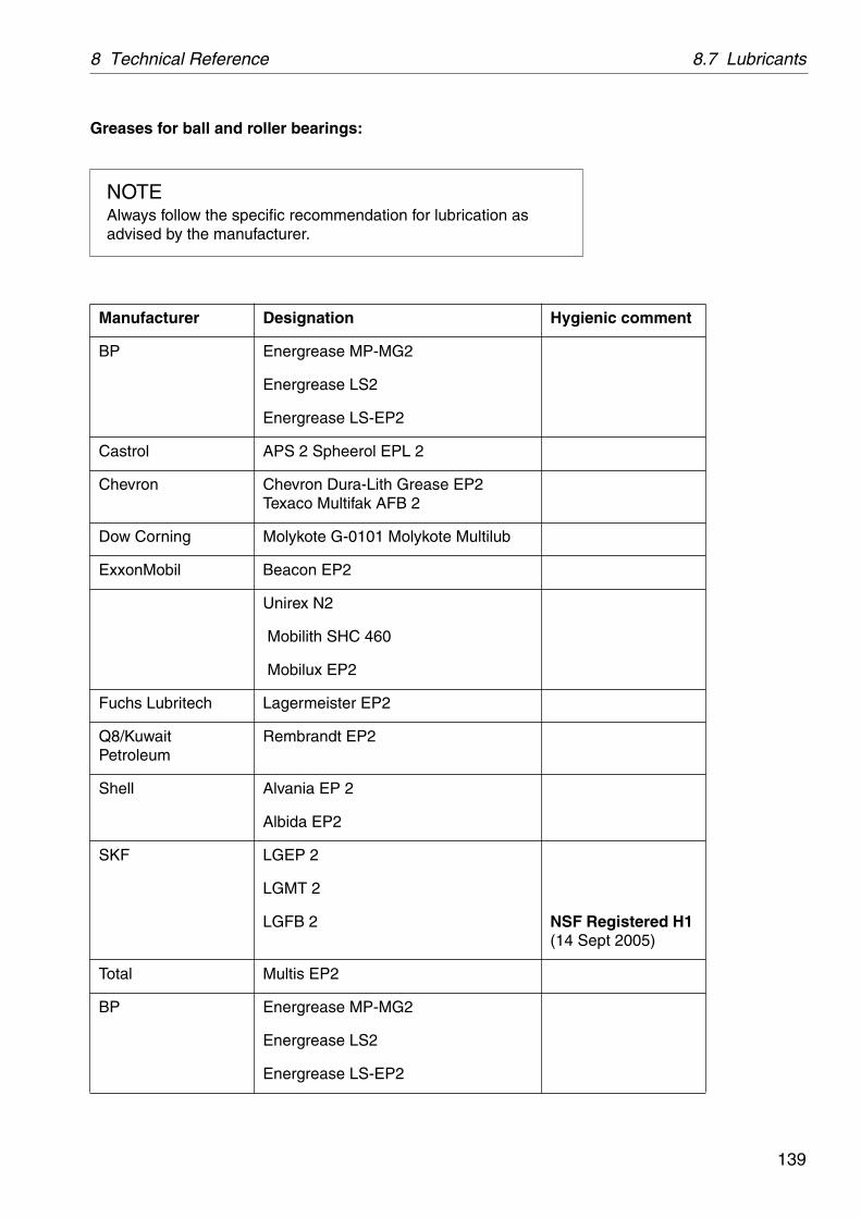
139
8 Technical Reference 8.7 Lubricants
Greases for ball and roller bearings:
NOTEAlways follow the specific recommendation for lubrication as advised by the manufacturer.
Manufacturer Designation Hygienic comment
BP Energrease MP-MG2
Energrease LS2
Energrease LS-EP2
Castrol APS 2 Spheerol EPL 2
Chevron Chevron Dura-Lith Grease EP2 Texaco Multifak AFB 2
Dow Corning Molykote G-0101 Molykote Multilub
ExxonMobil Beacon EP2
Unirex N2
Mobilith SHC 460
Mobilux EP2
Fuchs Lubritech Lagermeister EP2
Q8/Kuwait Petroleum
Rembrandt EP2
Shell Alvania EP 2
Albida EP2
SKF LGEP 2
LGMT 2
LGFB 2 NSF Registered H1(14 Sept 2005)
Total Multis EP2
BP Energrease MP-MG2
Energrease LS2
Energrease LS-EP2

8.7 Lubricants 8 Technical Reference
140
8.7.3 Recommended lubricating oils
Alfa Laval ref. 553219-09, rev. 0
Two different groups of lubricating oils are approved. They are designated as Alfa Laval lubricating oil groups A and D which are described on page 143.
The numerical value after the letter in the table states the viscosity grade..
The corresponding commercial oil brands are listed on next page.
Note:
When the separator is operated for short periods, lubricating oil must be changed every 12 months even if the total number of operating hours is less than stated in the recommendations above.
Check and prelubricate spindle bearings on separators which have been out of service for 6 months or longer.
In seasonal operation: change oil before every operating period.
Alfa Laval do not accept responsibility for any damage caused by the use of lubricants which deviate from the recommended lubricants listed in this manual.
Ambient temperature Alfa Laval lubricating oil group
Time in operation Oil change interval
between +15 and +45 °C A/150 1500 h
between +2 and +65 °C D/220 2000 h
S00
3242
1
Alfa Laval lube oil

141
8 Technical Reference 8.7 Lubricants
8.7.4 Recommended oil brands (04)
Alfa Laval ref. 553218-04, rev. 5
NOTE
The data in below tables is based on supplier information in regards to lubrication properties. Trade names and designations might vary from country to country, contact your local supplier for more information.
Brands with Alfa Laval article number are approved and recommended for use.
Paraffinic mineral lubricating oil category (ISO-L-) HM 150.Viscosity grade (ISO 3448/3104) VG 150.
The oil shall follow the requirements in one of the standards below.
Standard Designation
ISO 11158, (ISO 6743/4) ISO-L-HM or HV 150
ISO 12925-1, (ISO 6743/6) ISO-L-CKC or CKE 150
DIN 51524 part 2 or 3 (German standard) DIN 51524 - HLP or HVLP 150
DIN 51517 part 3 DIN 51517 - CLP 150
The following is a list of recommended oil brands. Trade names and designations might vary from country to country. Please contact your local oil supplier for more information. Brands with Alfa Laval article number are approved and recommended for use.
Alfa Laval lubrication oil group AViscosity grade VG (ISO 3448/3104)Viscosity index VI (ISO 2909)
VG 150VI >95
Manufacturer DesignationAlfa Laval 546098-81 (4 litres)
546098-83 (1 litre )BP Bartran 150
Bartran HV 150Castrol Alpha ZN 150
Hyspin AWH(-M) 150

8.7 Lubricants 8 Technical Reference
142
Chevron Rando HD150Paper Machine Oil XL 150
ExxonMobil Mobil DTE PM 150Mobil DTE 19M (ISO VG 150)Mobil Vacuoline 528 (ISO VG 150)Nuto H 150
Q8/Kuwait Petroleum Haydn 150
Shell Morlina 150
Statoil LubeWay XA 150
Total Azolla ZS 150Lubmarine Visga 150
The list of recommended oil brands is not complete. Other oil brands may be used as long as they have equivalently quality as the brands recommended. The oil shall follow the requirements in one of the standards above. The use of other lubricants than the recommended is done on the exclusive responsibility of the user or oil supplier.
Paraffinic mineral lubricating oil category HM 150 for hygienic applications.
Conform to U.S. Food and Drug Administration (FDA) requirements of lubricants with incidental food contact, Title CFR 21 178.3570, 178.3620 and/or those generally regarded as safe (US 21 CFR 182).
Lubrication oils for food and hygienic applications
Viscosity grade VG (ISO 3448/3104)Viscosity index VI (ISO 2909)
VG 150VI >95
Manufacturer Designation
ExxonMobil Mobil DTE FM 150 (Mineral/PAO)
Bel-Ray Bel-Ray No-Tox Gear Oil 85Bel-Ray No-Tox Anti-wear 40
Total Keystone Nevastane EP 150
The hygienic oils on the list are all in the online "NSF White Book™ Listing" at the time of the revision of this document. For more information about the NSF registration and up to date H1 registration, see www.nsf.org (http://www.nsf.org/business/nonfood_compounds/)

143
8 Technical Reference 8.7 Lubricants
8.7.5 Recommended oil brands (08)
Alfa Laval ref. 553218-08 rev. 5
Synthetic lubricating oil, category PAO (ISO-L-) CKE 220
Viscosity grade (ISO 3448/3104) VG 220.
The following are lists of recommended oil brands. Trade names and designations might vary from country to country, contact your local oil supplier for more information.
Brands with Alfa Laval article number are approved and recommended for use.
Alfa Laval lubrication oil group D
Manufacturer Designation
Alfa Laval 542690-84 20 litres replacement for 542690-80
542690-85 4 litres replacement for 542690-81
BP Enersyn HTX 220Enersyn EP-XF 220
Castrol Alphasyn EP 220Alphasyn HG 220Optigear Synthetic A 220
Chevron Tegra Synthetic Gear Lubricant 220 (H2)Texaco/Caltex Pinnacle EP 220FAMM Pinnacle Marine Gear 220
ExxonMobil Mobil SHC 630
Q8/Kuwait Petroleum Schumann 220
Shell Omala RL 220
Statoil Mereta 220
Total Carter SH 220Elf Epona SA 220
The lists of recommended oil brands are not complete. Other oil brands may be used as long as they have equivalently quality as the brands recommended. The oil must have the same viscosity class and ought to follow the ISO standard 12925-1, category ISO-L-CKC, CKD, CKE or CKT (ISO 6743-6) or DIN 51517, part 3 CLP, but shall have a synthetic base oil of polyalphaolefin type (PAO) instead of mineral base oil. The oil must be endorsed for worm gear with brass worm wheel. The use of other lubricants than recommended is done on the exclusive responsibility of the user or oil supplier.

8.7 Lubricants 8 Technical Reference
144
Synthetic lubricating oil, category PAO (ISO-L-) CKE 220 for hygienic applications
Conform to U.S. Food and Drug Administration (FDA) requirements of lubricants with incidental food contact, Title CRF 21 178.3570, 178.3620 and/or those generally regarded as safe (US 21 CRF 182).
Lubrication oils for food and hygienic applications
Manufacturer Designation
Shell Cassida fluid GL 220
The hygienic oil on the list is in the online “NSF White BookTM Listing” at the time of the revision of this document. For more information about the NSF registration and up to date H1 registration, see www.nsf.org (http://www.nsf.org/business/nonfood_compounds/)

145
8 Technical Reference 8.8 Drawings
8.8 Drawings
8.8.1 Foundation planAlfa Laval ref. 557416, rev. 0
A 8 holes for foundation boltsB Service side
G06
0651
1

8.9 Electric motor 8 Technical Reference
146
8.9 Electric motorAlfa Laval ref. 551821, rev. 9
Manufacturer ABB MotorsManufacturers drawing CAT. BA/Marine motors GB 08-2001Standards IIEC 34-series, 72, 79 and 85Size 100LType M2AA 100 LWeight 21 kgPoles 2Insulation class FBearings D-end 6306-2Z/C3
N-end 6205-2Z/C3 Method of cooling IC 411 (IEC 34-6)Specification Totally enclosed three-phase motor for marine service 3)
Type of mountingIEC 34-7
Degree of protectionIEC 34-5
IM 3011 IP 55
A
B
C
D G08
3115
1
A. Knock out openings for 2 x M25cable glands on both sides.
B. Sheet-steel fan hood.C. 4 holes ø15.D. Drain holes with closable plugs to be positioned
t lowest point for IM 3011 mounting position.

147
8 Technical Reference 8.9 Electric motor
1. lst /l = startingcurrent / rated current at direct on line starting.
2. Thermistors tripping temperature if applicable.
3. The motors can be designed to fulfil requirements of the following Classification Societies:(Essential Service if required)
Required classification society must always be specified when ordering. Factory test certificate to be enclosed at the delivery.Rated output (kW) valid for temperature rise max. 90 C.
The motors can be provided with space heaters for 110V or 220V 25W as option.State supply voltage when ordering.Connection to separate terminal board in the main terminal box acc. to attached connection diagram.
The rotor balanced with half key.Max. vibration velocity 1,8 mm/s (rms) according to IEC 34-14.
Lloyds Register of shipping (LRS) Nippon Kaiyi Kyoaki (NK)Det Norske Veritas (DnV) Korean Register of Shipping (KR)
Germanischer Lloyd (GL) Polski Rejester Statkow (PRS)
Bureau Veritas (BV) China Classification Society (CCS)American Bureau of Shipping (ABS) Indian Register of Shipping (IRS)
Registro Italiano Navale (RINA) Maritime Register of Shipping (RMS)
NOTEThe motor bearings are permanently lubricated.
NOTEFor complete information about motor variants,please contact your Alfa Laval representative.

8.10 Electric motor (Crompton Greaves) 8 Technical Reference
148
8.10 Electric motor (Crompton Greaves)
Alfa Laval ref. 580793, rev. 0
A. Cable entry.B. Sheet-steel fan hood.C. 4 holes ø14,5.
Manufacturer Crompton Greaves Ltd.Manufacturers drawing Cat. Crompton Greaves Ltd TEFC, SCRStandards IEC 34-series, 72, 79 and 85Size IEC 100Type GD 100Weight 27 kgPoles 2Insulation class FBearings D-end 6306-2Z
N-end 6205-2ZMethod of cooling IC 411 (IEC 34-6)Specification Totally enclosed three-phase motor for marine service 3)
Type of mountingIEC 34-7
Degree of protectionIEC 34-5
IM 3011 IP 55
A
B
C
G08
3116
1

149
8 Technical Reference 8.10 Electric motor (Crompton Greaves)
The rotor balanced with half key.
Max. vibration velocity 1,8 mm/s (rms) according to IEC 34-14.
1. I/st/I = starting current/rated current at direct on line starting.
2. Thermistors tripping temp. if applicable
3. All ratings can be CSA marked
Factory test certificate to be enclosed at the delivery.Rated output (kW) valid for temp. rise max 80°C.
The motors can be provided with space heaters for 110V or 220V 25W as option. State supply voltage when ordering.Connection to separate terminal board in the main terminal box according to attached connection diagram.
NOTEThe motor bearings are permanently lubricated.
NOTEFor complete information about motor variants,please contact your Alfa Laval representative.

8.10 Electric motor (Crompton Greaves) 8 Technical Reference
150
8.10.1 Machine plates and safety labels
Alfa Laval ref. 559214, rev. 2
1. Machine plate
Separator
Manufacturing serial No / Year
Product No
Inlet and outlet
Bowl
Machine bottom part
Max. speed (bowl)
Direction of rotation (bowl)
Speed motor shaft
El. current frequency
Recommended motor power
Max. density of feed
Max. density of sediment
Process temperature min./max.
G06
0641
1
S00
6141
1

151
8 Technical Reference 8.10 Electric motor (Crompton Greaves)
3. Safety label
Text on label:
WARNING
Read the instruction manuals before installation, operation and maintenance. Consider inspection intervals.
Failure to strictly follow instructions can lead to fatal injury.
If excessive vibration occurs, stop separator and keep bowl filled with liquid during rundown.
Out of balance vibration will become worse if bowl is not full.
Separator must stop rotating before anydismantling work is started.
4. Name plate
6. Power supply frequency
7. Label
Text on label:
Read the instruction manual before lifting.
A. Space for label indicating representative
XXXXX XXX XXXX XXX
XXXXX XXXX X XXXX XXX
XX.
XXX XXX X XXX XX XXXX
XXXX XX X X XXXXX XXX
X XXX XXXX XXX XX XX X
X XXX X XXX.
XX X XXXXX XX X XXXX
XXX XXX X XXXXXX
XXX XXX XXX X XXXXX
XXX X XXXX .
XXXXXXXXXXXXXXXXX
XXXX XXXX XXXX
XXXXXXXXXXXX XXX
XXXXXXX XXXXX XX
XXXXX XXXXXXX
XXXXXXXXX.
XXXXXXX/XX,X XX
W A R N I N G
XXXXX X XXXXX XX X
XXX XX XXX XXX XX X.
!
S00
690N
1S
0063
211
S00
6311
1S
0069
111

8.10 Electric motor (Crompton Greaves) 8 Technical Reference
152
8.10.2 Gravity disc nomogram
Example 1 in nomogram Example 2 in nomogram
Reference in graph: _________ Reference in graph: _ _ _ _ _ _ _
Oil density 915 kg/m3
at 15 °C (60 °F)Oil density 875 kg/m3
at 15 °C (60 °F)
Separation temperature 70 °C (150 °F)
Separation temperature 40 °C (95 °F)
Throughput 3,9 m3/h Throughput 4,5 m3/h
From the graphs (heavy line), the correct gravity disc has a hole diameter of 66 mm.
From the graphs (broken line), the correct gravity disc has a hole diameter of 73 mm.
G01
7372
1
Oil density, kg/m3 at 15 oC Gravity disc hole diameter, mm
Oil temperature, °C, °F Throughput, m3/h

153
8 Technical Reference 8.11 Storage and installation
8.11 Storage and installation
8.11.1 Storage and transport of goods
Storage
Specification
Upon arrival to the store, check all components and keep them:
1. Well stored and protected from mechanical damage and theft.
2. Dry an protected from rain and humidity
3. Organized in the store in such a way that the goods will be easily accessible when installation is about to take place.
A separator can be delivered with different types of protection:
Fixed on a pallet.
The separator must be stored in a dry storage room, protected from rain and humidity. It must be well protected from mechanical damage and theft.
S00
2141
1
Fixed on a pallet

8.11 Storage and installation 8 Technical Reference
154
In a wooden box which is not water tight.
The separator must be stored in a dry storage room, protected from rain and humidity.
In a special water-resistant box for outdoor storage.
The separator and its parts have been treated with an anti-corrosion agent. Once the box has been opened, store dry and protected from rain and humidity.
The packaging for outdoor storage is only to special order.
S00
2151
1
In a wooden box which is not water tight
S00
2161
1
In a special water-resistant box for outdoor storage

155
8 Technical Reference 8.11 Storage and installation
Transport
Specification
During transport of the separator, the bowl must always be removed from the machine and transported separately.
When lifting a separator it must always be hung securely. See details in chapter ‘‘5.6 Lifting instructions” on page 59.
During erection, all inlets and outlets to separators and accessories must be covered to be protected from dust and dirt.
WARNING
Crush hazards
Use correct lifting tools and follow lifting instructions.
G01
6153
1
H = minimum 750 mm

8.11 Storage and installation 8 Technical Reference
156
8.11.2 Planning of installation
Introduction
The space required for one or more separators can be calculated by consulting ‘‘8.3 Basic size drawing” on page 126, and instructions for ancillary equipment, electrical and electronic equipment and cables.
Important measurements
Important measurements are the minimum lifting height for lifting tackle, shortest distance between driving motor and wall, free passage for dismantling and assembly, maintenance and operation.
Plan your installation with sufficient room for the controls and operation so that instruments are easily visible. Valves and controls must be within convenient reach. Pay attention to space requirements for maintenance work, work benches, dismantled machine parts or for a service trolley.
Space for separator
The separator shall be placed in such a way that suitable space for maintenance and repair is obtained.
Specification
See the ‘‘8.8.1 Foundation plan” on page 145 for the service space required with the separator installed.
Recommendation
The spanner for the bowl hood should have sufficient space to make a complete turn without touching any of the ancillary equipment surrounding the separator.
G00
2061
1
Check the drawings when planning the installation
G00
2072
1
Suitable space must be obtained for the maintenance work

157
8 Technical Reference 8.11 Storage and installation
Lifting height for transport of bowl
Specification
A minimum height is required to lift the bowl, bowl parts and the bowl spindle, see the drawing ‘‘8.8.1 Foundation plan” on page 145.
Recommendation
When two or more separators are installed, the lifting height may have to be increased to enable parts from one separator to be lifted and moved over an adjoining assembled separator.
Space for oil changing
Specification
The oil filling device must not be blocked by floor plate arrangement, etc.
Recommendation
It should be possible to place a portable collecting tray under the oil filling device drain hole.

8.11 Storage and installation 8 Technical Reference
158
8.11.3 Foundations
Specification
The separator should be installed at floor level, see ‘‘8.8.1 Foundation plan” on page 145.
The separator must be installed on a strong and rigid foundation to reduce the influence of vibrations from adjacent machinery.
The foundation should be provided with a cofferdam.
Fit the separator frame on the foundation as follows:
Check that the bolts do not press against the edges of the holes, otherwise the elasticity of the mounting of the separator frame will be impeded.
Fit height adjusting washers required.
Check that the separator frame is horizontal and that all feet rest on the foundation.
Tighten the screws.
NOTE
When lifting a separator it must always be hung securely. See the separate lifting instruction in this book.

159
Reader’s Comment Form
Dear reader,
It is our ambition to produce as useful and instructive manuals as possible. Should you have any comments (positive or negative) regarding this manual, please note them down and send them to us. You can do this by copying this page and sending it by fax, or you could mail it, or hand it over to your local Alfa Laval representative.
Alfa Laval Tumba AB, Separator Manuals, dept. PPDM, SE-147 80 Tumba, Sweden. Fax: +46 8 530 310 40.
Your name: Company:
Address: City:
Country:
Product: MMB 305S-11 Book No.: 1271228-02 Rev. 4
Date:
Yes No
Is it easy to find what you are looking for by using the table of contents? ❒ ❒
Are the chapter and section headings clear and adequate? ❒ ❒
Is the information presented in the correct order for your purposes? ❒ ❒
Does the information in the manual cover your needs? ❒ ❒
Is it easy to understand the instructions in the manual? ❒ ❒
Is the terminology sufficiently explained? ❒ ❒
Are the illustrations easy to understand? ❒ ❒
Your comments:

160

161
Order Form
If you wish to order extra copies of this manual, please copy this page and give it to your local Alfa Laval representative, who will advise you of current prices.
Your local Alfa Laval representative will also be able to help you with information regarding any other manuals.
Your name: Company:
Address: City:
Country:
Product: MMB 305S-11 Book No.: 1271228-02 Rev. 4
Quantity: Date:
Comments:

162

163
Index
A
AdjustmentsBelt tension 107Paring disc 57
Application 21Assembly 71
Bowl spindle and frame 92Bowl, inlet/outlet 79Tools 72
B
Basic principles of separation 18Bearings, directions for 67Belt
Belt drive, description 25Replacement 104Retightening 108Tightening 104
Belt drive 25Bowl
Assembly 79Dismantling 73Function 23
Bowl discsCleaning 63Disc stack pressure 56
Bowl spindle and frameAssembly 92Dismantling 87
Bowl spindle, description 25Brake 36
Description 26Exploded view 110Friction element 111
C
Centrifugal separation 18Check points
Corrosion 48Cracks 51Disc stack pressure 56Erosion 50Paring disc 52Spindle top cone and bowl body nave 53Threads of inlet pipe 52Threads on bowl hood and bowl body 54
ClarificationDescription 23
Clarifier disc 24Cleaning 61Connections
Connection list, specifications 128Dimensions 127
Corrosion 48Coupling
Assembly 101Dismantling 99
Cracks 51
D
Daily checks 43Dimensions
Connections 127Direction of rotation 33Disc stack pressure 56Dismantling 71
Bowl spindle and frame 87Inlet/outlet, bowl 73Tools 72
Displacement of oil (in bowl) 24Drawings 145
Dimensions of connections 127Foundation plan 145Machine plates and safety labels 150Motor 146, 148
E
Emergency stop, see Safety stop 36Emptying intervals, sludge 37Erosion 50
F
Foundation plan 145Frame feet
Replacement 112Friction coupling 25
Assembly 101Dismantling 99
Function descriptionSeparator 22Separator bowl 23

164
G
Gravity discNomogram 152Selection 30
Gravity disc, purification 24
I
Inlet/outletAssembly 86Dismantling 73
Inspection slot, bowl hood 33Installation 153Installation planning 156Interface to other equipment, description 129Interface, oil/water in bowl 24
L
Lifting instructions 59Lubrication
Lubrication chart 133
M
Machine plates 150Maintenance
Intervals 40Procedure 42
Motor 130, 146, 148Motor current at start 34
N
Noise 117
O
Oil discharge through water outlet 122Oil filling device
Exploded view 109Oil sump
Oil change interval 44Oil change procedure 64Recommended lubricating oils/brands 140
Operation 29
P
Periodic maintenance 40Power transmission, mechanical
Belt drive 25Bowl spindle 25Friction coupling 25
PurificationDescription 23
R
Recommended oil brands 141Rotation, direction 33
S
Safety Instructions 9Safety labels 150Safety stop 36Separation result, unsatisfactory 122Separation, basic principles 18Separator does not start 115Separator vibrates 117Service intervals 40Service kits 42Service logs 45, 46Shut-downs 70Smell 117Speed
Speed too high 118Start 30, 31, 34
Separator vibrates 116Starting power too high 115Starting power too low 115Start-up period 34Start-up time too long 115
StopSafety stop 36Stopping procedure 35
Storage 153
T
Technical data 124, 125Tools 72Transport of separator 155Trouble-tracing 113
V
VibrationDuring start 34Safety stop 36
W
Warning signs 14Water seal (purification) 24