SEOUL PRECISI N OPTICS - SPO · 2012-10-29 · SEOUL PRECISI N OPTICS Since 1996 _ Transparent ITO...
16
SEOUL PRECISI N OPTICS Since 1996 _ Transparent ITO Multiple Cavity Metal-dielectric Filters Fluorescence Filter Gas Analysis Filter Motion / Intrusion Filter Beam Splitter IR Anti-Reflection Optical coating & Technical support
Transcript of SEOUL PRECISI N OPTICS - SPO · 2012-10-29 · SEOUL PRECISI N OPTICS Since 1996 _ Transparent ITO...

SEOUL PRECISI N OPTICSSince 1996_
Transparent ITO
Multiple Cavity Metal-dielectric Filters
Fluorescence Filter
Gas Analysis Filter
Motion / Intrusion Filter
Beam Splitter
IR Anti-Reflection
Optical coating & Technical support
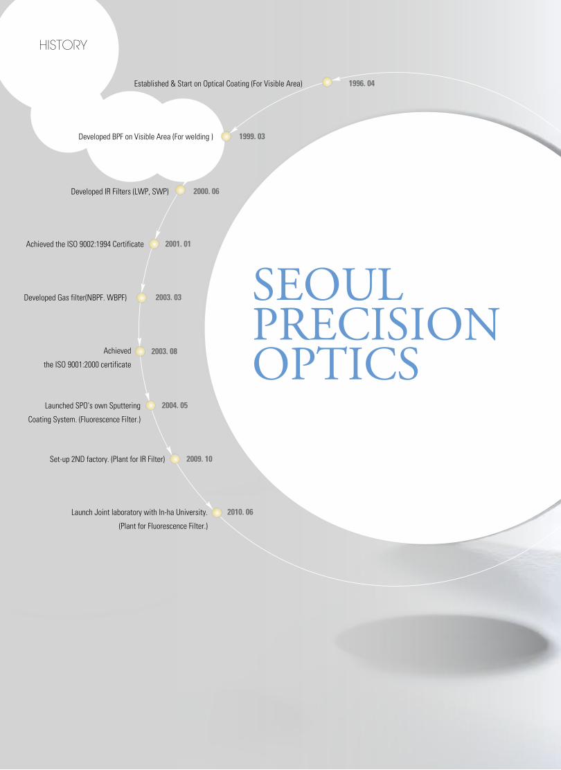
HiStory
Established & Start on Optical Coating (For Visible Area)
Developed BPF on Visible Area (For welding )
Developed IR Filters (LWP, SWP)
Developed Gas filter(NBPF. WBPF)
Achieved
the ISO 9001:2000 certificate
Launched SPO's own Sputtering
Coating System. (Fluorescence Filter.)
Set-up 2ND factory. (Plant for IR Filter)
Launch Joint laboratory with In-ha University.
(Plant for Fluorescence Filter.)
Achieved the ISO 9002:1994 Certificate
1996. 04
1999. 03
2000. 06
2001. 01
2003. 03
2003. 08
2004. 05
2009. 10
2010. 06
SEOUL PRECISION OPTICS

Vacuum deposition technology has progressed significantly over the years
and SPO has remain strong position in this dynamic field. Our current coating
designs are applied using some of the newest and most progressive deposition
procedures. Seoul Precision Optics offers its customers an uncommon collection of
technical depth, personalized service, and competitive pricing. We are committed
to manufacturing quality thin films through improved production method and
superior workmanship. Contact on of our sales engineers to discuss your specific
requirements. We look forward to applying our thin film technology and progressive
production methods to your application.
Very truly yours,
President
Chim Mun Sig
Seoul Precision Optics Co. has been supplying high quality optical coating based on partnership relation with customer for many years.
Optical coating & Technical support
Since 1996
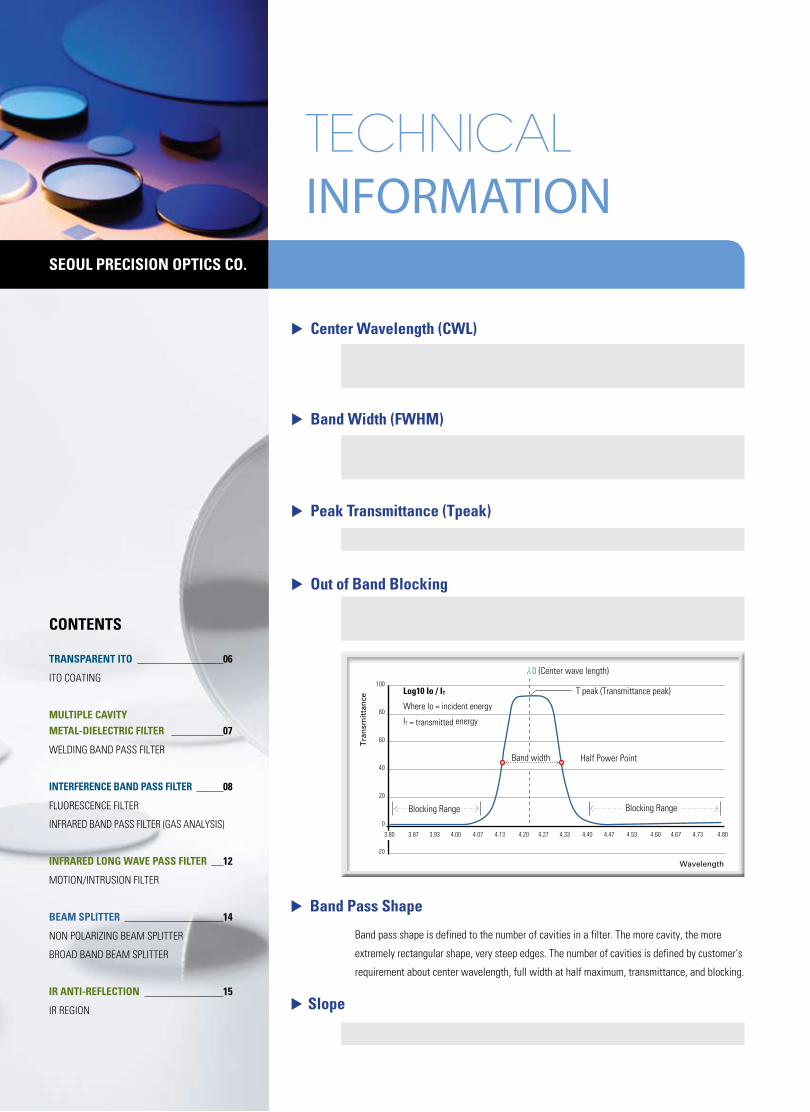
▶ Center Wavelength (CWL)
λ0 = ( λ1 + λ2 ) /2
Where λ1 and λ2 are the wavelength at 50% of Peak Transmittance.
▶ Band Width (FWHM)
λ2 - λ1
Where λ1 and λ2 are the wavelength at 50% of Peak Transmittance.
▶ Peak Transmittance (Tpeak)
T peak = Maximum transmittance with in the band pass region.
▶ Out of Band Blocking It is the amount of energy to the total energy out side the band pass.
Commonly refer to as signal to noise ratio (S/N), or it is usually express in Optical Density (O.D).
▶ Band Pass Shape
Band pass shape is defined to the number of cavities in a filter. The more cavity, the more
extremely rectangular shape, very steep edges. The number of cavities is defined by customer's
requirement about center wavelength, full width at half maximum, transmittance, and blocking.
▶ Slope
%SLOPE = {λ(80%)-λ(5%) /λ(5%)} x 100%
tecHnical information
CONTENTS
TraNSParENT iTO 06
ITO COATING
MuLTiPLE CaviTy METaL-diELECTriC FiLTEr 07
WELDING BAND PASS FILTER
iNTErFErENCE BaNd PaSS FiLTEr 08
FLUORESCENCE FILTER
INFRARED BAND PASS FILTER (GAS ANALySIS)
iNFrarEd LONg WavE PaSS FiLTEr 12
MOTION/INTRUSION FILTER
BEaM SPLiTTEr 14
NON POLARIzING BEAM SPLITTER
BROAD BAND BEAM SPLITTER
ir aNTi-rEFLECTiON 15
IR REGION
T peak (Transmittance peak)
Band width Half Power Point
Tra
nsm
itta
nce
Wavelength
Blocking Range Blocking Range
λ0 (Center wave length)
Log10 io / iT
Where lo = incident energy
IT = transmitted energy
100
80
60
40
20
0
-20
3.87 3.93 4.00 4.07 4.13 4.20 4.27 4.33 4.40 4.47 4.53 4.60 4.67 4.73 4.803.80
SEOuL PrECiSiON OPTiCS CO.
Seo
ul Precisio
n O
ptics co
Tech
nical In
form
ation
Pro
du
cts
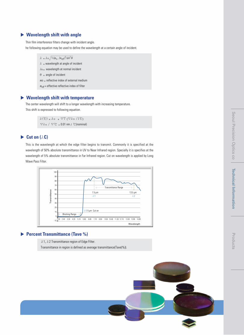
▶ Percent Transmittance (Tave %) λ1, λ2 Transmittance region of Edge Filter.
Transmittance in region is defined as average transmittance(Tave(%)).
▶ Wavelength shift with angleThin film interference filters change with incident angle.
he following equation may be used to define the wavelength at a certain angle of incident.
λ= λο1-(nο/neff )2 sin2 θ
λ= wavelength at angle of incident
λο=wavelength at normal incident
θ=angle of incident
no = reflective index of external medium
neff = effective reflective index of filter
▶ Wavelength shift with temperatureThe center wavelength will shift to a longer wavelength with increasing temperature.
This shift is expressed to following equation.
λ(℃)=λο+▽T(▽λο/1℃)
▽λο/▽℃= 0.01 nm /℃(nominal)
▶ Cut on (λC)This is the wavelength at which the edge filter begins to transmit. Commonly it is specified at the
wavelength of 50% absolute transmittance in UV to Near Infrared region. Specially it is specifies at the
wavelength of 5% absolute transmittance in Far Infrared region. Cut on wavelength is applied by Long
Wave Pass Filter.
Wavelength
Blocking Range5 µm Cut on
7.5 µm 13.5 µm
Transmittance Range
λ0
λ1 λ2
Tra
nsm
itta
nce
100
90
80
70
60
50
40
30
20
10
0
-10
100
90
80
70
60
50
40
30
20
10
0
-101.50 2.40 3.30 4.20 5.10 5.90 6.80 7.70 8.60 9.50 10.40 11.30 12.10 13.00 13.90 14.80

▶ Ordering information
Seoul Precision Optics Co.
Coating Type rs(%) Trasmission(%) Passivation Filter Number
One Side ITO 10±15 > 87 CALL S-ITO-10
One Side ITO 50±15 > 85 CALL S-ITO-50
One Side ITO 100±15 > 85 CALL S-ITO-100
One Side ITO 200±15 > 85 CALL S-ITO-200
Both Side ITO 10±15 > 80 CALL B-ITO-10
Both Side ITO 50±15 > 80 CALL B-ITO-50
Both Side ITO 100±15 > 80 CALL B-ITO-100
Both Side ITO 200±15 > 80 CALL B-ITO-200
One Side ITO with AR 10±15 > 90 CALL SA-ITO-10-
One Side ITO with AR 50±15 > 90 CALL SA-ITO-50-
One Side ITO with AR 100±15 > 90 CALL SA-ITO-100-
One Side ITO with AR 200±15 > 90 CALL SA-ITO-200-
Other Radio and sizes are available upon request
▶ applicationTouch pannel, TFT-LCD, industrial management
system
▶ Property Using Magnetron sputtering, ITO coating has
excellent durability from the environmental
impact. 을 을을을
을 을을을 을 을을을을을 을을을
▶ general Specification·Substrate
Float Glass(soda-lime)
·Dimension(mm) 100mm x 200mm
·Transmission
Index Mached ITO : over 90% at 450mm~700mm
ITO : over 85% at 550nm
·Electrical Resistivity
Most ITO coated glass is available in surface
resistivities from 5 ohms/square to 1000 ohms/
squre.
06
ITO coated products are manufactured to meet specifications of surface resistance and transmittance. Adhesion and corrosion resistance for these coatings are excellent.Many film designs are available for glass and plastic substrates to meet various ohms per square and transmission requirements.
Seoul Precision Optics Co.
iTO Coating
▶ Without anti-reflection coated iTO ▶ With anti-reflection coated iTO
Wavelength in nanometers
Transmission > 85%
White Light
% T
ran
smis
sio
n
100
90
80
70
60
50
40
30
20
10
500 600 700 8000
Wavelength in nanometers
Transmission > 90%
White Light
% T
ran
smis
sio
n100
90
80
70
60
50
40
30
20
10
500 600 700 8000
Transparent ITO

▶ application
Auto Darkening welding Helmet
▶ Property
Block the UV and IR lights for protecting human's
eye during their welding process.
Reflection color & visual transmittance can be
designed based on customer's request.
▶ Quality passed all aNSi and EN specification
* american National Standards institute
(aNSi) Z87.1-1989(2 FEB.89)
Standard Practice for Occupational and Education
Eye and Face Protection.
* European Standard EN 169:1992
Filter for Personal Eye-protection Equipment used
in Welding and Similar Operations.
uv. ir cut filter
Welding Band pass filter
Auto Darken welding cartridge is used for "high efficiency" and to protect eyes from the noxious light during the welding process. Welding band pass filter is a key component of Auto Darken welding cartridge. It blocks UV & IR and is designed to adjust transmittance of Visible light. Welding filter can customize the transmittance at all of wavelength depending on the working environment and the type of welding. The filter can come in different sizes based on customer's inquiry.
Metal-dielectric FilterMultiple cavity
y
x
0.9
0.8
0.7
0.6
0.5
0.4
0.3
0.2
0.1
0.00.0 0.1 0.2 0.3 0.4 0.5 0.6 0.7 0.8
ITO C
oatin
g | W
eldin
g B
and
pass fi
lter | Fluorescence Filter | Gas A
nalysis Filter | Motion / Intrusion filter | N
on Polarizing Beam
Splitter ·B
road Band B
eam Splitter | IR
Anti R
egion
07
500
380460470
480
490
520
540
560
580
600
620
700
▶ Multiple cavity metal dielectric filters
Tra
nsm
itta
nce
40
35
30
25
20
15
10
5
0
Wavelength380 430 480 530 580 630 680 730 780 830 880
▶ Multiple cavity metal dielectric filters
Tra
nsm
itta
nce
40
35
30
25
20
15
10
5
0
Wavelength380 530 680 980 1130 1280 1430830 1580 1730 1880 2030 2180
Optical coating & Technical support

08
Fluorescence filter set is composed of an excitation filter, an emission filter, and a dichroic beamsplitter. A filter set may be designed to work with a single fluorophore or with multiple fluorophores simultaneously. The Superior precision and repeatability of the Magnetron sputtering or Evapolator deposition platform enables the realization of filters with exceptional blocking levels, high transmission levels, and very steep transition zones. The practical result in fluorescence based applications is bright, high-contrast images.
Band Pass FilterInterference
Seoul Precision Optics Co.
visible band pass filter
Fluorescence Filter
▶ application Fluorescence microscopy, Flow cytometry, DNA
microarray scanners, Real-timme PCR, Imaging
systems.
▶ Property High peak transmission, Deep blocking over
wide spectral ranges, precise edge placement,
Hard dielectric coating/epoxy free optical path
▶ general Specification· Transmission for filter.
Passband transmission Typically over 90%
Blocking Transmission Typically 0.01%, OD4
· Surface Quality
60-40 scratch-dig as per MIL- STD- 48497A
· Physical Durability
MIL-C-48497A
· Coating type
“Hard” Magnetron Sputtered–epoxy free.
Seoul Precision Optics Co. Seoul Precision Optics Co.
For best results, select excitation and emission filters with center wavelengths as close to the absorptive and emissive peaks as possible. This gives the best possible yield from the selected dye.
Wavelength(nm)
Excitation FilterEmission Filter
Dichroic Beamsplitter
100
0400 500 600 700
%T
Wavelength(nm)
AbsorptionSpectrum
EmissionSpectrum
— Exciter— Dichroic— Emitter
Tra
nsm
issi
on
(%)
400 450 500 550 600
100
90
80
70
60
50
40
30
20
10
0

Other Radio and sizes are available upon request 09
▶ Ordering information
fluorochromes and stains
• AMCA
• Cascade blue
• Coumarin
• Dansyl
• DAPI
• Dialkylaminocoumarin (375/470)
• Dialkylaminocoumarin (435/475)
• DIPI
• Hoechst
• Pyrenes
• Acridine Orange (DNA)
• BOBO-1
• Bodipy-fl
• CY2
• Dabsyl chloride
• DiOC6(3)
• DiOC7(3)
• DTAF
• ELF-97
• Eosin
• Eosin F3S
• FITC
• GFP
• Hydroxystilbamidine(fluorogold)
• IANBD amide
• Lucifer yellow
• MitoFluor green
• MitoTracker green
• Oregon green 488
• Oregon green 500
• Oregon green 514
• Rodamine green
• Rhodol green
• SYTO 16
• TOPRO-1
• TOTO-1
• YOPRO-1
• YOYO-1
• Bodipy R6G
• Bodipy 530/550
• Bodipy TMR
• Bodipy 558/568
• Carboxyrhodamine 6G
• CY3
• DiA
• Dichloro-dimethoxyfluorescein
• DiI
• JOE
• B-Phycoerythrin
• R-Phycoerythrin
• POPO-3
• POPRO-3
• Rhodamine 6G
• SYTO 25
• TAMRA(carboxytetramethylrhodamine)
• TRITC(teramethylrhodamine isothiocyanate)
• BoBo-3
• Bodipy 576/589
• Bodipy 589/617
• BOPRO-3
• Chromomycin A3
• Cy3.5
• Dihydroethidium
• DIOC2(5)
• DiQ
• Ethidium Bromide
• Ethidium homodimer-2
• Hexidium iodide
• Lissamine rhodamine B
• MitoTracker red
• Propidium iodide
fluorochromes and stains
• Radiant redTM
• Rhodamine Red
• Texas red
• Texas red-X succinimidyl ester
• XRITC
• Acridine orange (RNA)
• Allophycocyanin
• 7-aminoactinomycin D
• Bodipy 630/650
• CY5
• LDS 751
• Napthofluorescein
• TOPRO-3
• TOTO-3
• CellTracker Blue
• DAPI
• DPH
• Fura-2
• Hoechst
• Hydroxycoumarin 385/445
• Hydroxycoumarin 360/455
• Indo-1
• Laurdan
• LysoSensor Blue DND-192
• Methoxycoumarin
• Prodan
• BCECF
• Bilirubin
• Bodipy FL brefeldin A
• Calcein
• Calcium green
• Carboxyfluorescein
• CellTracker Green Bodipy
• CFDA
• Cl-NERF
• DiOC5(3)
• DiOC16(3)
• DM-NERF
• Fluo-3
• 5 hexadecanoyl fluorescein
• JC-1 (low)
• LysoSensor Green DND-153
• LysoTracker green DND-26
• NBD-C6 ceramide
• Rhodamine -123
• Stachyose fluorescein
• Calcium orange
• DiC18(3)
• DiC16(3)
• LysoTracker Yellow DND-68
• MitoTracker Orange
• Octadecyl Rhodamine B
• Rhodamine B Hexyl ester
• SNARF (Acid)
• Tetramethylrosamine
• Bodipy TR ceramide
• DASPMI
• DiA
• DiD
• DiQ
• FM1-43
• LysoTRacker Red DND-99
• SNARF (Base)
• Sulforhodamine 101
• Sulforhodamine B
• Sulforhodamine G
• Sulfonerhodamine Bis-(PEG 2000)
• Fura red
• Napthofluorescein
• RH-414
Excitation Max (nm)
349
400
384
340
359
375
435
364
346
341
487
462
505
489
335
484
482
493
345
524
535
494
395 / 470
385
478
428
489
490
493
503
511
502
499
488
515
514
491
491
528
534
542
558
520
550
491
522
547
525
546 / 565
565 / 546 / 480
534
539
525
521
544
570
576
589
575
458
581
518
579
562
510
528
518
570
578
536
Excitation Max (nm)
500
570
587
583
572
487
650
555
630
650
543
598
642
642
353
359
354
346
385
360
335
364
374
340
361
439 / 490
452
503
494
506
492
522
494
518
484
484
515
506
497
514
442
504
466
505
491
549
549
534
551
556
556
490
550
589
475
491
644
562
510
577
490
586
565
529
557
436 / 500
605
532
Emission Max (nm)
448
420
470
520
461
470
475
455
460
376
520
481
513
506
536
501
504
518
530
544
542
518
509
536
541
533
517
516
520
522
530
527
525
518
531
533
509
509
550
554
574
569
546
565
590
550
565
555
575
578
570
567
555
556
572
604
590
617
599
590
596
605
601
600
595
617
600
590
599
617
Emission Max (nm)
610
590
602
603
596
650
661
655
650
670
712
668
661
660
466
461
430
460
445
455
405 / 490
497
424
405
498
530
525
510
517
533
517
529
517
544
500
501
542
526
519
529 / 590
505
511
536
533
516
565
565
551
576
578
578
580
574
617
605
590
665
681
626
590
630
605
586
548
581
640
675
716
ITO C
oating | Welding B
and pass filter | Fluo
rescence Filter | G
as Analysis Filter | M
otion / Intrusion filter | Non Polarizing B
eam S
plitter ·B
road Band B
eam S
plitter | IR A
nti Region
10
infrared Filter
gas analysis Filter
▶ general Specification
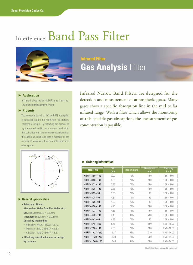
•Substrate:Silicon. (germanium Wafer, Sapphire Wafer, etc.)
dia. :100.00mm+0.30 / -0.30mm Thickness : 0.525mm+ / -0.025mm durability test method
- Humidity : MIL-C-48497A 4.5.3.2. - Moderate : MIL-C-48497A 4.5.3.3. - Adhesion : MIL-C-48497A 4.5.3.1.
•Blockingspecificationcanbedesign by custome
Other Radio and sizes are available upon request
Band Pass FilterInterference
Infrared Narrow Band Filters are designed for the detection and measurement of atmospheric gases. Many gases show a specific absorption line in the mid to far infrared range. With a filter which allows the monitoring of this specific gas absorption, the measurement of gas concentration is possible.
Model No CWL(um) Transmittanc Bandwidth
(nm)Blocking
(um)
NBPF - 3.09 - 160 3.09 70% 160 1.50 ~ 8.00
NBPF - 3.30 - 160 3.30 70% 160 1.50 ~ 8.00
NBPF - 3.33 - 160 3.33 70% 160 1.50 ~ 8.00
NBPF - 3.35 - 190 3.35 70% 190 1.50 ~ 8.00
NBPF - 3.95 - 90 3.95 76% 90 1.50 ~ 8.00
NBPF - 4.24 - 90 4.24 70% 90 1.50 ~ 8.00
NBPF - 4.26 - 90 4.26 76% 90 1.50 ~ 8.00
NBPF - 4.26 - 180 4.26 76% 180 1.50 ~ 8.00
NBPF - 4.33 - 160 4.33 73% 160 1.50 ~ 8.00
NBPF - 4.40 - 700 4.40 80% 700 1.50 ~ 8.00
NBPF - 4.43 - 60 4.43 70% 60 1.50 ~ 8.00
NBPF - 5.48 - 850 5.48 76% 850 1.50 ~ 10.00
NBPF - 7.30 - 180 7.30 70% 180 1.50 ~ 10.00
NBPF - 10.27 - 210 10.27 65% 210 1.50 ~ 14.00
NBPF - 11.30 - 200 11.30 70% 200 1.50 ~ 14.00
NBPF - 12.40 - 180 12.40 65% 180 1.50 ~ 14.00
▶ applicationInfrared absorpt ion (NDIR) gas sensing,
Environment management system
▶ PropertyTechnology is based on infrared (IR) absorption
of radiation called the NDIR(Non – Dispersive
Infrared) technique. By detecting the amount of
light absorbed, within just a narrow band width
that coincides with the resonance wavelength of
the specie selected, one gets a measure of the
number of molecules, free from interference of
other species.
Seoul Precision Optics Co.
1.6±0.7
1.5±0.5
5,6
60±3˚ ▶ Ordering information
11
ITO C
oating | Welding B
and pass filter | Fluorescence Filter | Gas A
nalysis Filter | M
otion / Intrusion filter | Non Polarizing B
eam S
plitter·Broad B
and Beam
Splitter | IR
Anti R
egion
Wavelength
Tra
nsm
itta
nce
100
80
60
40
20
0
1.50 2.00 2.50 3.00 3.50 4.00 4.50 5.00 5.50 6.00 6.50 7.00 7.50 8.0
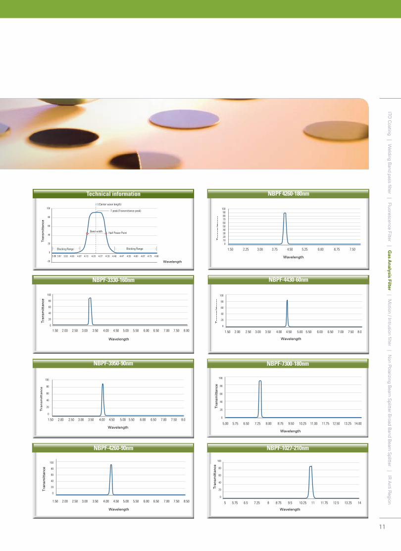
NBPF-4430-60nm
Wavelength
100
80
60
40
20
0
Tra
nsm
itta
nce
5.00 5.75 6.50 7.25 8.00 8.75 9.50 10.25 11.00 11.75 12.50 13.25 14.00
NBPF-7300-180nm
Wavelength
Tra
nsm
itta
nce
100
80
60
40
20
0
1.50 2.00 2.50 3.00 3.50 4.00 4.50 5.00 5.50 6.00 6.50 7.00 7.50 8.00
NBPF-3330-160nm
Wavelength
Tra
nsm
itta
nce
100
80
60
40
20
0
5 5.75 6.5 7.25 8 8.75 9.5 10.25 11 11.75 12.5 13.25 14
NBPF-1027-210nm
Wavelength
100
80
60
40
20
0
Tra
nsm
itta
nce
1.50 2.00 2.50 3.00 3.50 4.00 4.50 5.00 5.50 6.00 6.50 7.00 7.50 8.50
NBPF-4260-90nm
Wavelength
T peak (Transmittance peak)
Half Power Point
Tra
nsm
itta
nce
Blocking Range Blocking Range
λ0 (Center wave length)100
80
60
40
20
0
-20
3.80 3.87 3.93 4.00 4.07 4.13 4.20 4.27 4.33 4.40 4.47 4.53 4.60 4.67 4.73 4.80
Band width
Technical information
Wavelength
Tra
nsm
itta
nce
100908070605040302010
0
1.50 2.25 3.00 3.75 4.50 5.25 6.00 6.75 7.50
NBPF 4260-180nm
Wavelength
Tra
nsm
itta
nce
100
80
60
40
20
0
1.50 2.00 2.50 3.00 3.50 4.00 4.50 5.00 5.50 6.00 6.50 7.00 7.50 8.0
NBPF-3950-90nm
infrared Long Wave Pass Filter
Motion / intrusion Filter
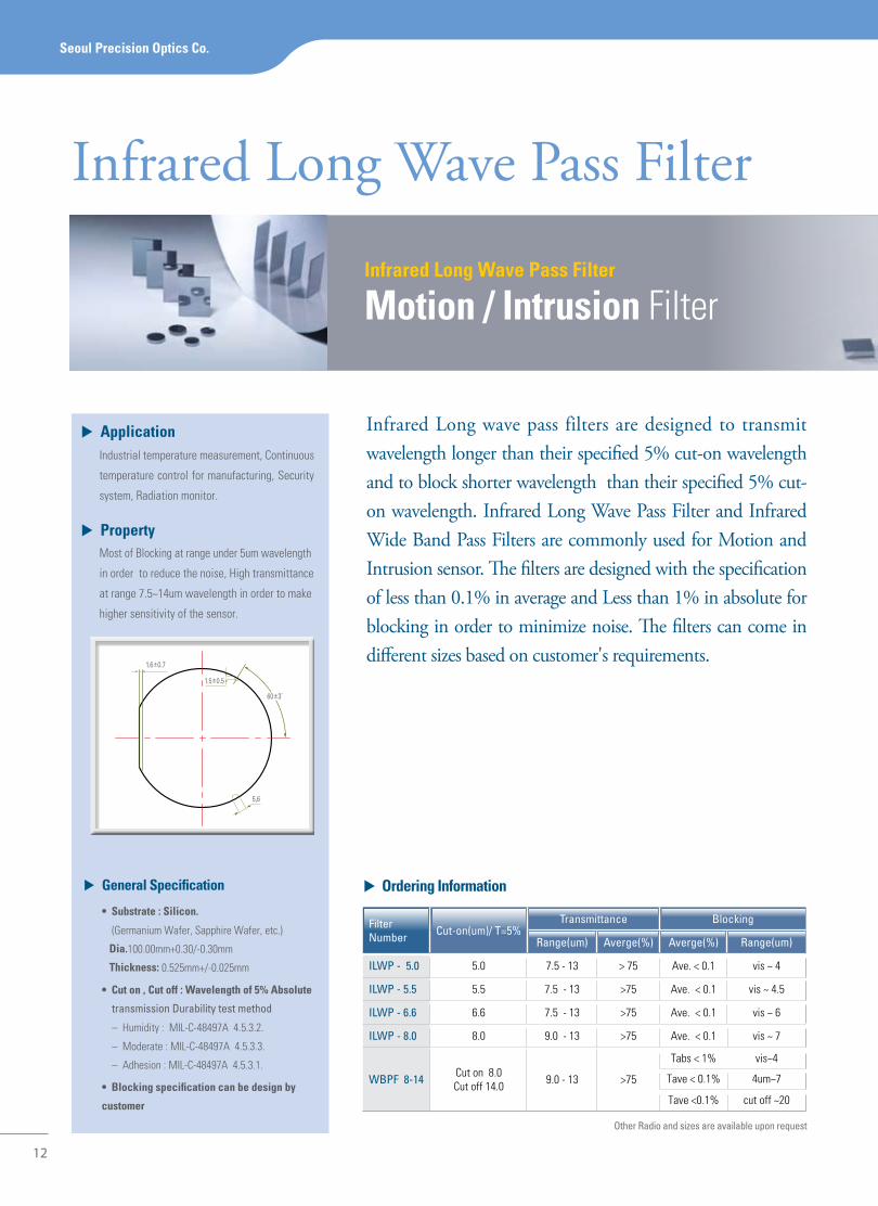
▶ general Specification
•Substrate:Silicon.
(Germanium Wafer, Sapphire Wafer, etc.)
dia.100.00mm+0.30/-0.30mm
Thickness: 0.525mm+/-0.025mm
•Cuton,Cutoff:Wavelengthof5%Absolute
transmission Durability test method
– Humidity : MIL-C-48497A 4.5.3.2.
– Moderate : MIL-C-48497A 4.5.3.3.
– Adhesion : MIL-C-48497A 4.5.3.1.
•Blockingspecificationcanbedesignby
customer
12
Infrared Long Wave Pass Filter
▶ Ordering information
Other Radio and sizes are available upon request
Filter Number Cut-on(um)/ T=5%
Transmittance Blocking
Range(um) Averge(%) Averge(%) Range(um)
ILWP - 5.0 5.0 7.5 - 13 > 75 Ave. < 0.1 vis ~ 4
ILWP - 5.5 5.5 7.5 - 13 >75 Ave. < 0.1 vis ~ 4.5
ILWP - 6.6 6.6 7.5 - 13 >75 Ave. < 0.1 vis ~ 6
ILWP - 8.0 8.0 9.0 - 13 >75 Ave. < 0.1 vis ~ 7
WBPF 8-14 Cut on 8.0Cut off 14.0 9.0 - 13 >75
Tabs < 1% vis~4
Tave < 0.1% 4um~7
Tave <0.1% cut off ~20
Infrared Long wave pass filters are designed to transmit wavelength longer than their specified 5% cut-on wavelength and to block shorter wavelength than their specified 5% cut-on wavelength. Infrared Long Wave Pass Filter and Infrared Wide Band Pass Filters are commonly used for Motion and Intrusion sensor. The filters are designed with the specification of less than 0.1% in average and Less than 1% in absolute for blocking in order to minimize noise. The filters can come in different sizes based on customer's requirements.
Seoul Precision Optics Co.
▶ applicationIndustrial temperature measurement, Continuous
temperature control for manufacturing, Security
system, Radiation monitor.
▶ PropertyMost of Blocking at range under 5um wavelength
in order to reduce the noise, High transmittance
at range 7.5~14um wavelength in order to make
higher sensitivity of the sensor.
1.6±0.7
1.5±0.5
5,6
60±3˚

13
Technical information
ir LWP 5.5
ir LWP 5.0
ITO C
oating | Welding B
and pass filter | Fluorescence Filter | Gas A
nalysis Filter | Mo
tion
/ Intru
sion
filter | N
on Polarizing Beam
Splitter·B
road Band B
eam S
plitter | IR A
nti Region
ir LWP 6.6
Wavelength
100
90
80
70
60
50
40
30
20
10
0
-101.52 2.62 3.73 4.84 5.95 7.05 8.16 9.27 10.38 11.48 12.59 13.70 14.81
Wavelength
100
90
80
70
60
50
40
30
20
10
0
-101.52 2.69 3.86 5.03 6.20 7.37 8.54 9.71 10.88 12.05 13.22 14.59 15.56 16.73 17.90 19.0
Tra
nsm
itta
nce
ir LWP 8.0
Wavelength
100
90
80
70
60
50
40
30
20
10
0
-101.52 2.62 3.73 4.84 5.95 7.05 8.16 9.27 10.38 11.48 12.59 13.70 14.81
Tra
nsm
itta
nce
Wavelength
1.52 2.62 3.73 4.84 5.95 7.05 8.16 9.27 10.38 11.48 12.59 13.70 14.81
100
90
80
70
60
50
40
30
20
10
0
-10
Wavelength
1.52 2.40 3.29 4.17 5.06 5.95 6.83 7.72 8.60 9.49 10.38 11.26 12.15 13.06 13.92 14.81
100
90
80
70
60
50
40
30
20
10
0
-10
Tra
nsm
itta
nce
Blocking Range
Transmittance Range
5um Cut on
7.5um 13.5um
λ0
λ1 λ2
100
90
80
70
60
50
40
30
20
10
0
-101.52 2.40 3.29 4.17 5.06 5.95 6.83 7.72 8.60 9.49 10.38 11.26 12.15 13.03 13.92 14.81
Wavelength
Tra
nsm
itta
nce
Tra
nsm
itta
nce
Tra
nsm
itta
nce
Wide Band Pass Fiter (8-14um)
14
Beam Splitter
Non Polarizing Beam SplitterBroad Band Beam Splitter
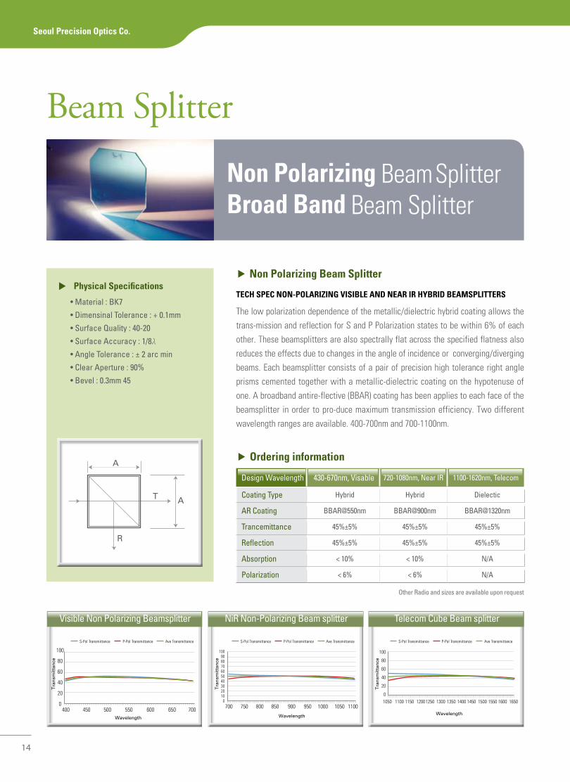
▶ Non Polarizing Beam Splitter
TECH SPEC NON-POLariZiNg viSiBLE aNd NEar ir HyBrid BEaMSPLiTTErS
The low polarization dependence of the metallic/dielectric hybrid coating allows the trans-mission and reflection for S and P Polarization states to be within 6% of each other. These beamsplitters are also spectrally flat across the specified flatness also reduces the effects due to changes in the angle of incidence or converging/diverging beams. Each beamsplitter consists of a pair of precision high tolerance right angle prisms cemented together with a metallic-dielectric coating on the hypotenuse of one. A broadband antire-flective (BBAR) coating has been applies to each face of the beamsplitter in order to pro-duce maximum transmission efficiency. Two different wavelength ranges are available. 400-700nm and 700-1100nm.
▶ Physical Specifications
• Material : BK7
• Dimensinal Tolerance : + 0.1mm
• Surface Quality : 40-20
• Surface Accuracy : 1/8λ
• Angle Tolerance : ± 2 arc min
• Clear Aperture : 90%
• Bevel : 0.3mm 45
▶ Ordering information
Design Wavelength 430-670nm, Visable 720-1080nm, Near IR 1100-1620nm, Telecom
Coating Type Hybrid Hybrid Dielectic
AR Coating BBAR@550nm BBAR@900nm BBAR@1320nm
Trancemittance 45%±5% 45%±5% 45%±5%
Reflection 45%±5% 45%±5% 45%±5%
Absorption < 10% < 10% N/A
Polarization < 6% < 6% N/A
Seoul Precision Optics Co.
Other Radio and sizes are available upon request
Visible Non Polarizing Beamsplitter NiR Non-Polarizing Beam splitter Telecom Cube Beam splitter
Wavelength Wavelength Wavelength
100
80
60
40
20
0400 450 500 550 600 650 700
100
80
60
40
20
01050 1100 1150 12001250 1300 1350 1400 1450 1500 1550 1600 1650
700 750 800 850 900 950 1000 1050 1100
1009080706050403020100
Tra
nsm
itta
nce
Tra
nsm
itta
nce
Tra
nsm
itta
nce
A
T A
R
S-Pol Transmittance P-Pol Transmittance Ave Transmittance S-Pol Transmittance P-Pol Transmittance Ave Transmittance S-Pol Transmittance P-Pol Transmittance Ave Transmittance

15
Optical coating & Technical support
Anti-Reflection
ir anti region
▶ anti-reflection
coating minimize surface reflection from optical systems.
Generally, there are three types of Anti-Reflection.
▶ Broad Band anti-reflection (iBar in infrared)
is used in many optical element in systems on sensor. This coatings are
characterized by very low anti reflection in broad spectrum range.
Other Radio and sizes are available upon request
Filter TypeTransmittance
SubstrateRange(um) T. Ave.
IRAR-3.0 3~ 13.5 74% Silicon
IRAR-4.24 4.24 97% Silicon
IRAR-3.5 3.5 ~ 5 95% Silicon
IRAR-7.5 7.5 ~ 13.5 95% Germanium. ZnS
▶ Ordering information
▶ Broad band Beam SplitterBroad band Beam Splitter is typically specified by the ratio of transmission to reflection. Seoul
Precision Optics can supply Beam Splitter at any required ratio and for any common laser beam.
▶ Ordering information
▶ general Specification
• Substrate : BK7 • Size Tolerance : +/- 0.1mm• Thickness : 2.0mm(nominal) to 3.0mm • AR Coating : <0.25 % per face• Angle of Incident : 45 degree
* Specification can be design by customer
Filter Number
BBS-80/20-
BBS-70/30-
BBS-60/40-
BBS-50/50-
BBS-40/60-
BBS-30/70-
R/T
80/20
70/30
60/40
50/50
40/60
30/70
Wavelength Range(mm)
450-650
450-650
450-650
450-650
450-650
450-650
Other Radio and sizes are available upon request
ITO C
oating | Welding B
and pass filter | Fluorescence Filter | Gas A
nalysis Filter | Motion / Intrusion filter | N
on
Polarizin
g B
eam S
plitter·B
road
Ban
d B
eam S
plitter | IR
An
ti Reg
ion
3-13.5um ar100
80
60
40
20
01.52 2.62 3.73 4.84 5.95 7.05 8.16 9.27 10.38 11.48 12.59 13.70
3.5-5um ar
Wavelength
Wavelength
100
80
60
40
20
01.52 2.62 3.73 4.84 5.95 7.05 8.16 9.27 10.38 11.48 12.59 13.70
7.5-13.5um ar
100
80
60
40
20
0
3.00 3.89 4.77 5.66 6.54 7.43 8.32 9.20 10.09 10.97 11.86 12.74 13.63 14
Tra
nsm
itta
nce
Tra
nsm
itta
nce
Tra
nsm
itta
nce
Wavelength
SEOUL
PRECISION
OPTICS
Seoul Precision Optics Sales Staff will be happy to answer any questions you have about our products. While most of our inventory
can be delivered the next day, we specialize in prototyping and manufacturing the optics you need. To e-mail your questions, please
use the appropriate addresses below.
Technical and Sales : [email protected]
Seoul precision optics Co.,
120-1, Chobu-Ri, Mohyun-Myun, Yongin-City, Kyunggi-Do, South Korea
Tel : +82-31-339-6092 Fax : +82-31-339-6094
Since 1996


![[Seoul e government] seoul map geospatial information platform](https://static.fdocuments.net/doc/165x107/58776db91a28ab5b568b5269/seoul-e-government-seoul-map-geospatial-information-platform.jpg)