
SentekTM PLUS All-in-OneTM...Sentek TM PLUS All-in-One TM & Sentek TM PLUS Compact DTU Hardware...
70
Sentek TM PLUS All-in-One TM & Sentek TM PLUS Compact DTU Hardware Manual Version 1.1
Transcript of SentekTM PLUS All-in-OneTM...Sentek TM PLUS All-in-One TM & Sentek TM PLUS Compact DTU Hardware...

SentekTM
PLUS All-in-OneTM
&
SentekTM
PLUS Compact DTU
Hardware Manual
Version 1.1

Copyright © 2005-2014 Sentek Pty Ltd All rights reserved Page i
All rights reserved. No part of this document may be reproduced, transcribed, translated into any language or transmitted in any form electronic or mechanical for any purpose whatsoever without the prior written consent of Sentek Pty Ltd. All intellectual and property rights remain with Sentek Pty Ltd.
All information presented is subject to change without notice.
2005-2015 Sentek Pty Ltd
Sentek™, EnviroSCAN™, EasyAG™, TriSCAN™, IrriMAX™, IrriMAX Live™ and Drill& Drop™ are trademarks or registered trademarks of Sentek Pty Ltd that may be registered in one or more jurisdictions.
Bluetooth™ is a trademark of the Bluetooth Special Interest Group (Bluetooth.org)
Android is a trademark of Google Inc.
NextG is a trademark of Telstra Corporation
Sentek Pty Ltd A.C.N. 007 916 672 77 Magill Road Stepney, South Australia 5069 Phone: +61 8 8366 1900 Facsimile: +61 8 8362 8400 Internet: www.sentek.com.au Email: [email protected]
All-in-One Rev 1.1 (2015-11-12)

Copyright © 2005-2014 Sentek Pty Ltd All rights reserved Page ii
SENTEK PLUS ALL-IN-ONE - STATEMENTS OF COMPLIANCE
FCC NOTE OF COMPLIANCE AND STATEMENT OF LIABILITY
Electro-Magnetic Compliance
This equipment has been tested and found to comply with the limits for a Class B digital device, pursuant to part 15 of the FCC rules. These limits are designed to provide reasonable protection against harmful interference in a residential installation. This equipment generates, uses, and can radiate radio frequency energy and, if not installed and used in accordance with the instructions, may cause harmful interference to radio communications. However, there is no guarantee that interference will not occur in a particular installation. If this equipment does cause harmful interference to radio or television reception, which can be determined by turning the equipment off and on, the user is encouraged to try to correct the interference by one or more of the following measures:
Reorientation or relocation of the receiving antenna.
Connection of the equipment into an outlet on a circuit different from that to which the receiver is connected.
Consultation with the dealer or an experienced radio/TV technician.
EMC approvals
The Sentek PLUS system complies with “EN61326:1997 Amdt 1:1998 Amdt 2:2001 Amdt 3:2003 EMC standard for equipment for measurement, control and laboratory use”.
The equipment complies with the following specifications:
- FCC Part 15 Class B. EN55011:1998, Amendment 1:1999 (Radiated and conducted emissions) - EN61000-4-2:1995 (Immunity to Electrostatic Discharge (ESD)) - EN61000-4-3:2002 (Immunity to Radiated Fields (RF)) - EN61000-4-4:1995 (Immunity to Electrical Fast Transients (EFT)) - EN61000-4-5:1995 (Immunity to Surges) - EN61000-4-6:1996 (Immunity to Conducted RF)
Marking
The above EMC approvals allow the product to be marked CE, C-tick and FCC.
Modifications
Any modifications to any part of the equipment or to any peripherals may void the EMC compliance of the equipment.
Radio Interference
The probe is not to be operated in free air as it may cause interference to radio communication devices
SENTEK BLUETOOTH MODULE
Product: PARANI-BCD210 Sena Technologies, Inc.
FCC
FCC Rule: Part 15 Subpart C Section 15.247
FCCID: S7AIW03
Compliance Statement

Copyright © 2005-2014 Sentek Pty Ltd All rights reserved Page iii
This device complies with part 15 of the FCC Rules. Operation is subject to the following two conditions:
(1) This device may not cause harmful interference, and
(2) This device must accept any interference received,
Including interference that may cause undesired operation.
Information to User
This equipment has been tested and found to comply with limits for a Class B digital device, Pursuant to Part15 of the FCC Rules. These limits are designed to provide reasonable protection against harmful interference in a residential installation.
This equipment generate(s), uses and can radiate radio frequency energy and, if not installed and used in accordance with the instructions, may cause harmful interference to radio communications.
However, there is no guarantee that interference will not occur in a particular installation. If this equipment does cause harmful interference to radio or television reception, which can be determined by turning the equipment off and on, the user is encouraged to try to correct the interference by one or more of the following measures:
- Reorient or relocate the receiving antenna.
- Increase the separation between the equipment and receiver-Connect the equipment into an outlet a circuit different form that to which the receiver is connected.
- Consult the dealer or an experienced radio/TV technician for help.
CE
Certification No: 1177
Declare under our own responsibility that the product Bluetooth Module
Brand name: SENA
Model No.: Parani-BCD210DU / Parani-BCD210DC / Parani-BCD210DS
Parani-BCD210SU / Parani-BCD210SC
To which this declaration refers conforms with the relevant standards or other standardizing documents
EN 60950-1
ETSI EN 301 489-1
ETSI EN 301 489-17
ETSI EN 300 328
According to the regulations in Directive 1999/5/EC
IC
Radio Cert. No.: IC: 8154A-IW03
KC
Type Registration
Certification No: KCC-CRM-SNA-IW03
TELEC
Technical Regulations for Specified Radio Equipment Article 2, Section 1 (19)
Certification No:
Parani-BCD210DU: 010WWBT0144
Parani-BCD210DC: 010WWBT0146
Parani-BCD210DS: 010WWBT0145

Copyright © 2005-2014 Sentek Pty Ltd All rights reserved Page iv
SIG
QDID: B019536
Model Name: Parani-BCD210
Core Version: 2.0+EDR
Product Type: Component
Declared Specifications: Baseband Conformance, Radio, Service Discovery Protocol,
Logical Link Control and Adaption Protocol, Generic Access Profile, Link Manager, RFCOMM,
Serial Port Profile, Host Controller Interface, Summary ICS, Product Type

Copyright © 2005-2014 Sentek Pty Ltd All rights reserved Page v
TABLE OF CONTENTS
Sentek PLUS All-in-One - Statements of Compliance ....................................... ii
FCC note of compliance and statement of liability .................................................................... ii EMC approvals ..................................................................................................................... ii
Sentek Bluetooth Module .......................................................................................................... ii FCC ...................................................................................................................................... ii CE........................................................................................................................................ iii IC ......................................................................................................................................... iii KC........................................................................................................................................ iii TELEC ................................................................................................................................. iii SIG ...................................................................................................................................... iv
Introduction ........................................................................................................... 1
Background .............................................................................................................................. 1 Features ................................................................................................................................... 1 Hardware Requirement Lists For Sentek PLUS All-in-One and Compact DTU ...................... 2
Required parts to assemble a complete All-in-One System ............................................... 2 Required parts to assemble a complete Compact DTU System ........................................ 3
Referenced Documents ........................................................................................ 5
System Setup ........................................................................................................ 6
Internet Provisioning ................................................................................................................ 6 Data Transfer and Hosting .................................................................................................. 6 Buying a SIM card and data packet plan for the modem .................................................... 6 Hosting Set-up and Recommendations .............................................................................. 8 Satellite firmware – Creating an email account ................................................................... 9 Satellite firmware – Registering modem with Iridium ........................................................ 10
Sentek PLUS All-in-One and Compact DTU Setup ............................................................... 11 Sentek All-in-One Probes ....................................................................................................... 13
Introduction ........................................................................................................................ 13 Sentek EnviroSCAN Sensors ............................................................................................ 13 Assemble and Normalise .................................................................................................. 13 Install access tube and the probe ..................................................................................... 14 Connecting External Antenna ........................................................................................... 14 Compact DTU Installation ................................................................................................. 15
Configuring the Probe with PConfig ....................................................................................... 16 Verifying Probe Configuration with Sentek Android App........................................................ 23 Modem Configuration ............................................................................................................. 30 Testing .................................................................................................................................... 32 Verifying Test Upload was Successful ................................................................................... 33 Viewing Data .......................................................................................................................... 34
Downloading ...................................................................................................................... 34 Viewing .............................................................................................................................. 34
Maintenance ........................................................................................................ 36
DTU ........................................................................................................................................ 36 Probe ...................................................................................................................................... 36 Lithium battery Life ................................................................................................................. 36 Firmware and Board Type ...................................................................................................... 37 Changing the Modem ............................................................................................................. 38 Firmware ................................................................................................................................ 38
Appendix A – Modem information ..................................................................... 40
Compatible Modems .............................................................................................................. 40 SIM Card Pin codes ............................................................................................................... 40 Useful AT Commands ............................................................................................................ 40
Extra Frequency Band information .................................................................................... 42

Copyright © 2005-2014 Sentek Pty Ltd All rights reserved Page vi
Appendix B – Network page explained ............................................................. 44
Appendix C – Upload Operation Diagram ........................................................ 45
Appendix D – PConfig Response Fields ........................................................... 46
Last Response ....................................................................................................................... 46 Test/Upload Result Codes ..................................................................................................... 46 Upload log .............................................................................................................................. 48
Appendix E - Technical Specifications ............................................................. 49
EnviroSCAN Series II 232 interface ....................................................................................... 49
Appendix F - Glossary of Terms........................................................................ 51
Appendix G - Configuring the Probe using Bluetooth on a Laptop ............... 53
Appendix H - Sentek PLUS Quick Reference Guide ........................................ 57
Product Set-up Checklist ........................................................................................................ 57 Preparation ........................................................................................................................ 57 Field Installation ................................................................................................................ 57 Software ............................................................................................................................ 57
Troubleshooting Guide ........................................................................................................... 58 Recommended Maintenance Schedules ............................................................................... 62
Daily................................................................................................................................... 62 6 months (or each time access tube is opened) ............................................................... 62 12 months .......................................................................................................................... 62 3 years ............................................................................................................................... 62

Copyright © 2005-2014 Sentek Pty Ltd All rights reserved Page vii
TABLE OF FIGURES
Figure 1 Block Diagram of the Sentek All-in-One in use .................................................... 1
Figure 2 Exploded All-in-One probe block diagram ............................................................ 3
Figure 3 Sentek PLUS All-in-One (GPRS, 3G/NextG & Satellite) .................................... 12
Figure 4 All-in-One connected to an EnviroSCAN Probe ................................................. 12
Figure 5 Probe connector All-in-One ................................................................................ 12
Figure 6 Bluetooth board and connections ....................................................................... 12
Figure 7 EnviroSCAN Moisture/ TriSCAN sensor addressing .......................................... 13
Figure 8 EnviroSCAN Temperature & Humidity Sensors (Showing address 1) ............... 14
Figure 9 EnviroSCAN interface and wiring diagram ......................................................... 14
Figure 10 External Antenna connector ............................................................................. 14
Figure 11 External Antenna connector ............................................................................. 15
Figure 12 PConfig connected to probe with default settings ............................................ 17
Figure 13 Auto-detected sensors...................................................................................... 17
Figure 14 Setting depths ................................................................................................... 18
Figure 15 Air counts and then Water counts .................................................................... 19
Figure 16 Clock page ........................................................................................................ 19
Figure 17 Edit screen ........................................................................................................ 20
Figure 18 Completed Logger page ................................................................................... 21
Figure 19 Network settings (with SIM Pin number) .......................................................... 22
Figure 20 Power settings .................................................................................................. 23
Figure 21 Android App Home Screen ............................................................................... 24
Figure 22 Bluetooth settings ............................................................................................. 24
Figure 23 Enabling Bluetooth ........................................................................................... 24
Figure 24 All-in-One Magnet switch position .................................................................... 25
Figure 25 Pairing with an All-in-One Probe ...................................................................... 26
Figure 26 Connection Successful prompt ......................................................................... 26
Figure 27 Probe Utility information screen ....................................................................... 26
Figure 28 Connection lost prompt..................................................................................... 27
Figure 29 Sensor test tab ................................................................................................. 28
Figure 30 Time tab ............................................................................................................ 29
Figure 31 Sending modem settings (Response from a GPRS modem)........................... 31
Figure 32 Sensor testing ................................................................................................... 32
Figure 33 Successful Test ................................................................................................ 32
Figure 34 Get Server files ................................................................................................. 33
Figure 35 Logger ID screen .............................................................................................. 34
Figure 36 Lithium Battery Discharge Characteristics ....................................................... 37
Figure 37 EnviroSCAN RS232 logging interface .............................................................. 37
Figure 38 Checking probe type and firmware versions .................................................... 39
Figure 39 Upload result codes from most recent upload attempt ..................................... 46
Figure 40 EnviroSCAN RS232 probe interface board layout ........................................... 50

Introduction
Background
Copyright © 2005-2014 Sentek Pty Ltd All rights reserved Page 1
INTRODUCTION
BACKGROUND
The Sentek PLUS All-in-One probe and Compact DTU option combine the scientifically and commercially proven sensor technology of EnviroSCAN, EasyAg probes and Drill & Drop probes, with web enabled, wireless communication.
In addition to this, Sentek PLUS also has the ability to continuously track fertiliser / salinity data through the use of TriSCAN sensors, and additionally on EnviroSCAN probes temperature and Humidity Sensors. Sentek All-in-One can utilise GPRS, NextG, CDMA (Verizon North. America) or Satellite communications to send soil water, fertiliser / salinity, Temperature humidity and voltage data from the probe to the user's PC via the internet. It also is equipped with Bluetooth which is used for wireless testing and configuration, using a laptop with the Probe Configuration Utility or an Android Device (phone or Tablet) with the Sentek Probe configuration utility. Alternatively, it provides for direct in-field download when services become unavailable in regional areas.
Figure 1 Block Diagram of the Sentek All-in-One in use
The Sentek PLUS Compact DTU expands the type of probes supported to include:
Connection cable with standard connector
EnviroSCAN RS232 probes (moisture, salinity, temperature and humidity which is equivalent to All-in-One)
EasyAG RS232 probes (moisture, salinity), and
Drill & Drop RS232 probes (Moisture, Salinity, Temperature)
FEATURES
Sentek PLUS All-in-One Probe
Utilises Sentek Soil Moisture & TriSCAN sensors, tubes and rod (optional temperature and humidity sensors)
Available to be retrofitted to EnviroSCAN screw cap probes and upgrade Diviner Sites
Cable Free, easy installation
Bluetooth configuration and testing
Interface can store over 2000 samples (~21 days @ 15 minute sampling intervals)

Introduction
Hardware Requirement Lists For Sentek PLUS All-in-One and Compact DTU
Copyright © 2005-2014 Sentek Pty Ltd All rights reserved Page 2
GPRS, NextG, CDMA or Satellite Communication Module
Internal Antenna or connector for an external antenna
Hi-capacity Lithium battery allowing 12 months of usage (based on Sentek standard configuration)
Facilitates direct communication from probe to a server computer via the Internet
Probe can come preconfigured for IrriMAX Live viewing
Sentek PLUS Compact DTU (Data Transmission Unit)
An assembled Sentek PLUS Compact DTU has all of the features of All-in-One, and additionally:
Integrated cable and connector for connection to EasyAg RS232 probe, EnviroSCAN screw cap or Flat cap RS232 probe or Drill & Drop RS232 Probe
Sentek PLUS sensor configurations
All-in-One and Compact DTU EnviroSCAN Screw-cap and Flat-Cap probes can be up to 1.2m long and contain one to 12 moisture/TriSCAN sensors, with optional Temperature & humidity sensors
Compact DTU can be configured with Drill & Drop probes which are available in 30cm to 120cm, containing 3, 6, 9 or 12 moisture or TriSCAN sensors. Each sensor also incorporates a temperature sensor
Compact DTU also supports EasyAg 30cm and 60cm probes containing 3 or 6 moisture/TriSCAN sensors.
The standard configuration contains 5/6 moisture or TriSCAN sensors, sampled each 30 minutes and uploaded to the Internet every 3 hours.
Note: Probes with large sensor configurations may shorten battery life and will
send more data on each upload. This can heavily impact monthly costs for Satellite uploads.
Sentek PLUS with IrriMAX software suite
Seamless download via Internet with Sentek IrriMAX Software
Network feature allows flexible modem configuration
Optional IrriMAX Live subscription which allows you to view your data on any Web enabled device (smartphone, Tablet and PC)
IrriMAX 9.1 or later is required to support Temperature and Humidity sensors
IrriMAX 10.0.3 or later is required to support Temperature/Humidity sensors on Satellite systems and Drill & Drop probes.
CDMA Support
All-in-One is supported for use with the Verizon CDMA network in North America. Probes are available pre-configured with CDMA modems and firmware and will work provided they are in an area with CDMA network access and Probe Configuration Utility Network tab has been appropriately setup.
HARDWARE REQUIREMENT LISTS FOR SENTEK PLUS ALL-IN-ONE AND COMPACT DTU
Required parts to assemble a complete All-in-One System
All-in-One External plastics
Assembled All-in-One Internal holder including Bluetooth module
GPRS, NextG, CDAM (USA) or Satellite Modem
14V 14Ah Battery

Introduction
Hardware Requirement Lists For Sentek PLUS All-in-One and Compact DTU
Copyright © 2005-2014 Sentek Pty Ltd All rights reserved Page 3
Internal antenna or Antenna with cable
RS232 EnviroSCAN or EasyAG Probe
Torch Magnet
Figure 2 Exploded All-in-One probe block diagram
Required parts to assemble a complete Compact DTU System
Compact DTU base and integrated cable with connector
Assembled All-in-One Internal holder including Bluetooth module
GPRS, NextG, CDMA (USA) or Satellite Modem
14V 14Ah Battery
GPRS, NextG, CDMA (USA) or Satellite Modem
Internal antenna or Antenna with cable
RS232 Probe (EnviroSCAN, EasyAG or Drill & Drop)
Torch Magnet
All-in-one internal plastic holder
Activation magnet point
EnviroSCAN Probe Interface
Probe Rod and sensors
All-in-one top cap plastics
EnviroSCAN probe plastics

Introduction
Hardware Requirement Lists For Sentek PLUS All-in-One and Compact DTU
Copyright © 2005-2014 Sentek Pty Ltd All rights reserved Page 4
Figure 3 Exploded Compact DTU block diagram
Plus Compact Base, with connection cable
Internal DTU with Modem and Bluetooth PCB
Hi-capacity Battery
Top Cap (Shown with optional external antenna connector

Referenced Documents
Hardware Requirement Lists For Sentek PLUS All-in-One and Compact DTU
Copyright © 2005-2014 Sentek Pty Ltd All rights reserved Page 5
REFERENCED DOCUMENTS
Access Tube Installation Guide
Sentek Drill & Drop Installation Guide
Sentek Flat Cap Installation Manual
Sentek Drill & Drop Probe Interface Manual
Android Probe Utility App User Guide
IrriMAX Data Exchange User Guide – Sentek PLUS Module
Probe Configuration Utility Manual 1.9.1 or later
Sentek Technical Brief - TB064-ESPlus NextG Fails Network Selection
Sentek Technical Brief - TB065-ESPlus NextG SIM PIN

System Setup
Internet Provisioning
Copyright © 2005-2014 Sentek Pty Ltd All rights reserved Page 6
SYSTEM SETUP
INTERNET PROVISIONING
Preparation, assembly and installation should generally be completed in the order of the steps in this section. Efficiencies might be gained by experienced installers altering the order of the steps taken.
The All-in-One when purchased as a complete probe has been normalised, preconfigured and tested to allow an easy and fast installation process. If purchased with the optional IrriMAX Live the probe will be pre-configured so that the probe Data will be transferred automatically to Sentek’s servers. Once the first upload has occurred the probe data will be available for viewing on an internet enabled device e.g., smartphone, tablet, etc.
Data Transfer and Hosting
A Sentek All-in-One probe must have access to the internet and somewhere to send its data. It needs a SIM card that will allow the modem to connect to the internet and a computer that is set up as an FTP server which can be accessed via the internet. The probe will make a connection to the internet at each upload interval, log in to the FTP server and copy the data files to the computer directory specified.
Sentek All-in-One probes with Satellite firmware* must have a satellite modem which is registered with the Iridium satellite network and it will also need an email account to which Iridium can forward the probe’s data. At each upload interval, the probe will power the satellite modem, which searches for satellites and then sends an -Irridium SBD file containing the readings to the satellite. The satellite will forward the SBD file as an email attachment to the email address/es that are registered for that modem.
Note: The internet access and FTP server should be set up prior to assembling and installing the hardware.
Buying a SIM card and data packet plan for the modem
Each Sentek All-in-One system will require a SIM card for the modem. This SIM card must have a data plan associated with it and must have reasonable coverage in the area where the probe will be installed. This data plan is similar to what is needed for accessing the internet on your mobile (cell) phone.
It is not necessary to get a plan with cheaper voice calls, SMS rates, voice mail options or other such features, as the probe will only use the data features of the plan, thus the GPRS or NextG data part of the plan must be the cheapest aspect.
When sourcing the SIM card and data plan make certain of the factors detailed below:
No Session Fees
Every time data is uploaded to the internet from the probe the network provider may charge what is called a session fee or flag fall. For systems uploading frequently this can become very expensive.
A typical session fee is around 25 cents. If uploads occur every 3 hours (8 uploads/day) this would cost around $60 per month, on top of data usage charges. Therefore, it is advised that a plan with no session fees be used.
Low Data Rates
To keep costs down, it is important when choosing a plan that you try to assess how much data you will be uploading, and how often you will be uploading it before choosing a plan accordingly.

System Setup
Internet Provisioning
Copyright © 2005-2014 Sentek Pty Ltd All rights reserved Page 7
Most data plans work in much the same way as a voice plan, costing a certain amount each month for a certain volume of data, and once this has been exceeded a charge for the excess data is applied.
Example plan:
Base cost of $5 per month
No session fees
2,000 KB included per month
1 cent per excess KB
If 1,800 KB is used, this plan will cost $5 per month, if however 2,200 KB is used in a month that month’s usage will come to $7.
A probe logging every 15 minutes and uploading every 90 minutes will use roughly 1,000 – 1,500 KB each month.
Uploading less often (which is recommended for power savings) will reduce data usage more than sampling less often (within certain limits), however a system that samples every 30 minutes, and uploads every 3 hours would transmit half as much data as the system described previously.
Note: Due to variable coverage, internet congestion or other circumstances, uploads may fail. The data will be available after the next successful upload,
but in areas where these issues occur, more frequent uploads may help ensure that data is accessible when required.
As every upload has a fixed overhead containing configuration information, it is advisable to maximise the number of samples per upload to reduce overhead data usage.
Table 1 Data Usage for different numbers of samples per upload
Overhead Useful Information (1 sample)
Overhead Useful Information (2 samples)
Overhead Useful Information (3 samples)
Overhead Useful Information (6 samples)
Naturally, the requirement for up-to-date data being available also needs to be considered. Sentek recommends that the All-in-One be set to sample every 30 minutes and upload every 3 hours. This gives a good balance between battery life and up to date data being available.
Data subscriptions are available with IrriMAX Live in some areas. Please contact your Account manager for more information.
Available Service
When choosing a service provider you should make certain that GPRS or NextG coverage is available in the area that you intend to install your system. It may also be useful to check the quality of service available. Unfortunately this is something that can

System Setup
Internet Provisioning
Copyright © 2005-2014 Sentek Pty Ltd All rights reserved Page 8
only be determined using local knowledge, as service providers’ estimates of their coverage are often overly optimistic, particularly in rural areas.
Hosting Set-up and Recommendations
When choosing or setting up a web server, there are a number of requirements that should be considered. These are outlined below.
FTP Server
It is essential that the host server support FTP access using port 21. FTP is the protocol used by the probe to upload data to the internet and without it the system cannot function. Port 21 is standard for FTP on the internet, and very few servers do not use it.
Fixed Address
Because the probe stores the address of the server in its internal memory the address for the server must be fixed. The server address should be associated with a static IP address or a domain name as it is essential that the address does not change or the probe will need to be reconfigured each time a change occurs.
Supporting Multiple Users
It is important that a server supports multiple users connecting at a time. It is possible in the case of multiple probe owners that more than one probe will try to upload at once, or that one or more users may attempt to use IrriMAX Data Exchange to log on and download from the server whilst a probe is uploading.
Although uploads can be staggered using the sample origin setting (see section Connecting External Antenna), it is desirable that the chosen server can support multiple FTP sessions connected at one time and potentially more than one session at a time using the same log in username and password.
File Storage Limits
Whilst the total amount of data uploaded by a single probe is not significant, there are a number of factors that may increase the required amount of storage well beyond what is expected.
A single probe is unlikely to upload more than 2000KB of data per month to be stored on the server. Data Exchange can be set to remove files older than a configurable number of days (the default is 90 days).
However, the cluster size of the server must be considered - this is the minimum size each file counts as on the hard disk. On most servers, this will be 4 or 8KB. This would mean, for example, that a directory containing 1500 files of 200 bytes each, would count for approximately 5.9MB on a server with a 4KB cluster size or 11.7MB on one with an 8KB cluster size, despite the total amount of data stored being less than 300KB. A server may therefore require at least 20MB of storage space per probe, depending on configuration.
The number of files allowed on a chosen FTP server may also cause problems. It is known that some servers restrict the total number of individual files to a maximum of around 50,000 or less, and many will truncate file lists at 2000 files.
A probe uploading every hour will produce 732 files in a month. Over 3 months, this amounts to around 2200 files. If the file list is truncated at 2000 files, even if Data Exchange is set to delete files older than 90 days, data from the most recent 8 days will appear to not be available to download, despite being on the server and the probe saying that it has been uploaded successfully.
Domain Registration
A static IP address can be used for the upload destination, but it is preferable to have an actual domain name.

System Setup
Internet Provisioning
Copyright © 2005-2014 Sentek Pty Ltd All rights reserved Page 9
When choosing between using a domain name or IP address, consideration must be given to the fact that when using an IP address, a change of this address will result in probes and download settings needing to be reconfigured, often on site by a trained technician.
When a server is attached to the internet it is given what is called an IP address. An IP address is a unique number to identify a machine connected to the internet - for example the original Sentek FTP server at ftp.enviroscanplus.com had an IP address of 72.9.224.170, but this has now changed. Provided that it is static (i.e. permanently assigned to that server), it is possible to configure a Sentek PLUS system to upload to an IP address.
However, this can be difficult to remember and is prone to error. When choosing a server you should also ask the host company about registering a domain name for that server. This way when setting up probes and downloading data, a normal URL (web site address or name) can be used instead of an IP address.
Data Allowance (Bandwidth)
Most web hosting agreements include a limit to the amount of data traffic (bandwidth) a server can receive during a month. Most companies offer around 500 MB a month as standard. Unless the server is hosting an extremely large number of probes, or is likely to have a large number of users downloading the data, this should be quite sufficient.
Regular Backups
Whilst it is not essential, it is strongly recommended that the host of your FTP server has a good backup strategy. This should include daily backups and some form of off-site data store. All reliable hosting companies will have something like this.
HTTP
IrriMAX Data Exchange has the ability to retrieve a directory listing and download the probe files over HTTP.
The main advantage of downloading over HTTP is that it is generally quicker when compared to FTP.
It should be noted that some servers, by default, do not enforce password protection for HTTP access, but can be configured with it. Also note that while some servers do not allow file alteration or deletion over HTTP, others do.
Note: FTP access is still required, as probes are only able to upload using FTP
HTTP is required for viewing Webified IrriMAX data. Having HTTP and FTP access to the server allows for it to be used for uploading and viewing of both probe and Webify data. For more information about Webify, see the IrriMAX Help.
Where to Buy
Numerous web hosting providers are available that offer packages that are suitable for use with Sentek PLUS. Due to the nature of the internet it is not essential that the hosting company be based in your home country. Many US based companies offer very competitive deals.
Alternatively, with your own IT support you can set up your own server machine to host the data. Provide your IT support person with this section of the manual when asking them to set up the server.
Satellite firmware – Creating an email account
Sentek PLUS (Satellite firmware) probes require an email account for the probe data to be forwarded. The emails must be on a POP mail server which is accessible to the PC on which IrriMAX will be downloading the data.

System Setup
Internet Provisioning
Copyright © 2005-2014 Sentek Pty Ltd All rights reserved Page 10
Where to buy
Some distributors may have their own mail servers with a personalised domain name. In this case the IT support person responsible for managing this mail server should be contacted and asked to create the new account/s. Remember to request the POP server address, account user name and password and information on whether SSL connection is needed.
Alternatively, there are many free mail account providers, such as Gmail, Yahoo and Zoho Mail which can provide the service needed. These accounts can easily be set up online and IrriMAX download settings be viewed in the providers’ settings area of their web site.
How many email accounts are needed?
There is no limit to how many probes’ data can be stored in one email account, however it is recommended that careful consideration be given to how many accounts will be required and what the addresses will be.
For example, consider that each PC downloading the data will require the mail account password and will have access to all emails in that account. So it would make sense to have a minimum of one account per customer or farm/site manager.
The total number of emails in the account inbox will only make a noticeable difference to the download speed the first time a Windows user downloads the data. Emails are cached on the user’s PC after each download to save having to download old emails again.
Storage
The email account will need a minimum of 1MB of storage per probe. This would be sufficient for approximately one years’ worth of data. However, Data Exchange will automatically delete emails older than 28 days.
The size of storage required in the email account will depend on the number of probes uploading into it, the value stated above is a guide only, but would be enough for a probe uploading relatively large amounts of data.
Backup
For extra data security, it is recommended that emails be forwarded to a second ‘backup’ account that is not used for downloading data. IrriMAX will automatically delete emails from the account that are older than 28 days (at the time of download).
Satellite firmware – Registering modem with Iridium
The Sentek PLUS (Satellite firmware) probe will send data to the satellite in the form of an Irridium SBD file. This file will only be forwarded on as an email attachment if there is an agreement in place with Iridium to do so. The Iridium network will identify the files by the modem IMEI. The modem IMEI must be matched to an email address in a contract with an Iridium reseller.

System Setup
Sentek PLUS All-in-One and Compact DTU Setup
Copyright © 2005-2014 Sentek Pty Ltd All rights reserved Page 11
Figure 3 Satellite Modem IMEI number location
Sentek currently has an agreement with an Iridium reseller which allows distributors to easily and cost effectively set up data forwarding contracts for their modems. Sentek distributors can request a copy of the partially completed order form from Sentek. This is the registration method recommended and supported by Sentek.
Alternatively, a distributor may arrange their agreement with an Iridium reseller, but Sentek is not obliged to provide assistance with this.
Note: Sentek have a data estimation program that can calculate approximate
expected monthly Satellite fees based on number of sensors and the upload interval. Please contact Sentek Technical Support for further information.
SENTEK PLUS ALL-IN-ONE AND COMPACT DTU SETUP
The Sentek All-in-One uses a modular plastic holder which is capable of holding various different modems. Below in Fugure 4, this shows complete All-in-One internal plastic holders which have been configured as GPRS, 3G/NextG & Satellite.

System Setup
Sentek PLUS All-in-One and Compact DTU Setup
Copyright © 2005-2014 Sentek Pty Ltd All rights reserved Page 12
Figure 3 Sentek PLUS All-in-One (GPRS, 3G/NextG & Satellite)
Figure 4 All-in-One connected to an EnviroSCAN Probe
Figure 5 Probe connector All-in-One
Figure 6 Bluetooth board and connections
Modem Connection cable Battery Connection cable Magnet Switch Probe Connection cable Bluetooth ID
Magnet Switch
Battery
Interface Probe Rod
Probe Handle
PConfig Connector Sensor

System Setup
Sentek All-in-One Probes
Copyright © 2005-2014 Sentek Pty Ltd All rights reserved Page 13
Note: All cables are pre-manufactured and plug into connectors
SENTEK ALL-IN-ONE PROBES
Introduction
Sentek All-in-One probes are configured using the Sentek software Probe Configuration Utility (PConfig) version 1.9.1 or later. The most recent version of PConfig is always available for download on the Sentek website. This hardware manual should be used in conjunction with the PConfig Help file.
EnviroSCAN Screw Cap probes can be used in a Sentek PLUS All-in-One system.
The Sentek All-in-One has been designed with the Sentek upgrade path in mind. It has built on the Modular type design of the EnviroSCAN probe, allowing rapid cost effective upgrade from Diviner or Solo sites to continuous data offered by the Sentek All-in-One.
Sentek EnviroSCAN Sensors
The Sentek All-in-One is compatible with all EnviroSCAN sensors such as Moisture, TriSCAN and Temperature and Humidity sensor. Moisture and TriSCAN sensors have been in use for many years now providing best in class measurement accuracy, and have been independently verified by numerous published research papers.
The Temperature and Humidity sensor has been a new addition to the Sentek sensor lineup, and gives accurate temperature measurements at the depths they are installed. The humidity measurement is used to track the humidity inside the access tube to help ensure the probe has been installed correctly. It will alert the user to potential excess moisture problems within their probes.
Assemble and Normalise
1. Assemble EnviroSCAN probes according to the EnviroSCAN Screw Cap assembly guides and as demonstrated during official distributor training. No assembly is required if a Complete All-in-One probe is purchased.
Figure 7 EnviroSCAN Moisture/ TriSCAN sensor addressing

System Setup
Sentek All-in-One Probes
Copyright © 2005-2014 Sentek Pty Ltd All rights reserved Page 14
Figure 8 EnviroSCAN Temperature & Humidity Sensors (Showing address 1)
2. Use PConfig to normalise each sensor on the probe. For detailed normalization instructions, refer to the “Normalizing the Sensor Air & Water Counts” section of the PConfig Help file. More basic step-by-step instructions can be found further down in the section Connecting External Antenna.
3. Temperature and Humidity sensors do not require calibration/normalization.
4. Label the probe and save back-ups of the normalization on your computer.
Install access tube and the probe
1. Install access tube as per the Sentek installation manuals and as demonstrated during official distributor training.
2. All-in-One probes are available in Standard install (undisturbed) and Slurry installation methods.
Figure 9 EnviroSCAN interface and wiring diagram
Connecting External Antenna
The All-in-One probe and Compact DTU come standard with an internal 2dB antenna which is fitted to the modem inside the plastic housing. If this antenna is not suitable for the area in which the All-in-One is to be installed an external antenna may be required. The All-in-One can be optionally fitted with an external antenna connection.
Figure 10 External Antenna connector
Early Versions of All-in-One Antenna Connection
Early versions had the antenna connection fitted to the Adaptor where the black cable gland is usually fitted, shown in Figure 11below.
Probe
Cable Red
Orange
Brown Black
Blue
Purple Green
Yellow

System Setup
Sentek All-in-One Probes
Copyright © 2005-2014 Sentek Pty Ltd All rights reserved Page 15
Figure 11 External Antenna connector
The patch cable can be routed through one of the two holes in the internal plastic holder or around the holder whichever is easier. This can then be connected to the antenna cable on the installed modem.
Note: The connector must be disconnected from the modem prior to removal of the plastic internal holder. The internal antenna patch cable must be clear of the sensors as the probe rod is removed. Failure to do this will cause the
antenna cable to be damaged.
Compact DTU Installation
1. Install Sentek RS232 Probe into the ground (EasyAg, EnviroSCAN Flat cap, Drill & Drop Installation guides)
2. Install Plus Compact DTU into the ground so that the access tube is in the soil and the DTU is stable in the soil. This can be done using a 56mm auger from an EnviroSCAN installation kit, or using a hand trowel. Please ensure the distance between the DTU and probe is less than 6 meters (20ft) so that the cable is long enough.
3. Connect the probe cable connector ensuring they are clean and free of any Dirt or debris.
4. Connect battery to internal Plastic holder
5. Slide the internal plastic holder into DTU Compact ensuring it is lined up correctly.
6. If it the unit is fitted with an internal antenna ensure that this is fitted and tightened adequately. If it has provision for an external antenna ensure this is connected to the modem antenna connection.

System Setup
Configuring the Probe with PConfig
Copyright © 2005-2014 Sentek Pty Ltd All rights reserved Page 16
7. Check cap to see that the seal is free of any dirt, apply a coating of silicon grease to seal.
8. Place cap on Compact ensuring the cap has locked onto the lugs correctly.
9. If using an external antenna ensure the antenna of extension cable is tightened onto cap.
CONFIGURING THE PROBE WITH PCONFIG
Introduction
Caution: Drill & Drop probe come preconfigured sensors and normalized, so you
should backup the configuration before making changes.
Before installing a Sentek All-in-One system in the field, the probe must have the following configured:
number of sensors detected and depths set
air and water counts normalised
sampling interval set
clock synchronised
Internet Destination URL
Sentek All-in-One specific settings (explained in detail below)
Some applications may also require configuration of the Calibration Equation constants and Power settings, although the default settings are usually sufficient.
Each of these procedures will be explained in the order that they should be performed. Additional information can be found in the Probe Configuration Utility manual.
Connecting to probe
The Sentek probe can be configured the using the probe interface TTL port. Ideally this would be done prior to installing the in the field. Once the probe is installed the Bluetooth connection can be utilised to check and test the probe. PConfig with laptop Bluetooth gives full functionality. The Android App can be used to query sensors and adjust the time and perform Modem test upload.
Note: The USB Probe Programming Cable for Drill & Drop probe has a different connector
The USB Probe Programming Cable (PConfig Cable) is used to communicate through the TTL port. Drivers for this cable must be installed before the cable is connected to the computer. Instructions on how to install the cable drivers can be found in Sentek Technical Brief TB069-PConfig USB cable driver installation instructions.
1. Use the Probe PConfig Cable to connect the TTL port of the interface to your computer.
2. Open PConfig,
3. Select the serial port that has been assigned to the cable
4. Select the baud rate of the interface TTL port (default = 9600)
5. Ensure that the Battery is connected and press Connect. The PConfig software should now establish communications with the probe.

System Setup
Configuring the Probe with PConfig
Copyright © 2005-2014 Sentek Pty Ltd All rights reserved Page 17
Figure 12 PConfig connected to probe with default settings
Configuration page
Caution: Drill & Drop probe come with sensors preconfigured and normalized so Auto-
detect Sensors, setting depths and normalization is not required.
1. Use the Auto-detect Sensors button to populate the sensor list in the Configuration page.
Figure 13 Auto-detected sensors
2. Set the depth of each sensor by clicking inside each cell within the Depth column and changing the number by either clicking the up and down arrows or by typing it on the computer keypad. Sensors with addresses from 65 – 80 will automatically update depths once all other configuration information has been entered and written.
Note: TriSCAN sensors display as two sensors in the Configuration page. The moisture sensing function will be addressed according to the jumper settings on the sensor (i.e. 1-16). The VIC function also depends on the physical addressing of the pins, but range from 65 to 80 (where physical
address 1 = 65 and 16 = 80)

System Setup
Configuring the Probe with PConfig
Copyright © 2005-2014 Sentek Pty Ltd All rights reserved Page 18
Temperature and Humidity Sensors when supplied with Moisture or TriSCAN sensors will take the sensor depth of the sensor. If a sensor is standalone, the depth will need to be set. The temperature and humidity sensors do not need to be calibrated/normalised. Temperature sensor addresses start at 161, Humidity Sensors start at 193.
Figure 14 Setting depths
3. To obtain the High (Air) counts for each sensor; place the probe inside its access tube. Then ensure that there are no obstacles (i.e. hands, cables, soil, tables etc.) within the sensor’s sphere of influence (keep >20cm radius clear) and click on the header row of the High/Air column so that the interface takes a reading from each sensor.
Note: Alternatively, the Air counts can be taken one sensor at a time by clicking on the lightning bolt next to each sensor
4. To obtain the Low (Water) counts, fill your Normalization Container with water, slide the probe into the access tube until the first sensor is in the middle of the container. In the Low/Water column click on the lightning bolt in the corresponding row of the sensor being read. Repeat for each sensor, and remember to take a water reading for both moisture and VIC when normalizing TriSCAN sensors.
Important: VIC water counts must be taken in reverse osmosis (RO) water (EC less than 300μScm-1). Always normalise sensors under the same
conditions to ensure maximum repeatability.

System Setup
Configuring the Probe with PConfig
Copyright © 2005-2014 Sentek Pty Ltd All rights reserved Page 19
Figure 15 Air counts and then Water counts
5. If required, enter custom calibration coefficients for each moisture sensor. Each coefficient should be separated by a semicolon (i.e. A;B;C). See the Calibration Manual for more information.
6. Save (write) these settings to the probe by clicking Write to Probe. The Configuration page is complete
Clock page
1. Click on the Clock tab to display the clock settings. Decide how often the probe should take a reading and set the desired sampling interval accordingly.
2. Set the probe clock to the desired time (usually probe local time) by either typing it in or synchronizing it with your computer clock.
Figure 16 Clock page
3. Write to Probe
Logger page
In PConfig versions earlier than 1.8.1, the “Logger” page was named “Plus/Solo”. If the “Logger” page does not appear when you are connected to the probe, either you do not have the latest version of PConfig, or the interface does not have the correct firmware loaded on it.
1. Click on the Logger tab to display identification, uploading, and modem communication details.
2. Type in a Logger ID specific to the probe so that the data can be identified later. This name is used to supply the IrriMAX database Logger ID. The default is the probe's serial number. The logger ID can be up to 16 alpha-numeric characters and underscores and cannot contain any spaces.
3. Set your desired Sample Origin. This determines when the first reading will be taken by the interface. All subsequent readings will use the Sample Origin as a starting reference. i.e. if the Sample Interval is 1 hour, and the Sample Origin is midnight, but the probe is only switched on at 7:05am, the first reading will occur at 8:00am, then 9am, 10am etc.

System Setup
Configuring the Probe with PConfig
Copyright © 2005-2014 Sentek Pty Ltd All rights reserved Page 20
Note: When you have many probes accessing a single mobile/cell phone tower, it is useful to stagger the Sample Origin across the probes by 5 minutes each
to prevent congestion, if all probes try to upload at the same time.
4. Set the Sample Count. For a Sentek All-in-One probe, this is the number of samples taken before an upload is initiated. A value of zero disables the upload process. For information on minimizing data costs, see the section Buying a SIM card and data packet plan for the modem.
5. Dial-in is disabled (Uptime set to 0) with the All-in-One probe. If enabled this will cause the probe to prematurely flatten the battery.
6. To complete the Destination URL field, click on the Edit button and enter in the FTP server details. Alternatively, the full URL can be typed in without going into Edit. The format of the URL is:
ftp://<user name>:<password>@<host/Internet address>/<url-path>
Your FTP server administrator should provide this information. If the URL is blank the upload process is disabled. For more information, see the section Hosting Set-up and
Recommendations.
Figure 17 Edit screen
7. Set the Connection Timeout. This is the maximum time (in seconds) allowed from the start of an upload until communications with the FTP server are established. If this time is exceeded the upload attempt is abandoned. The default of 60 seconds is generally sufficient. Altering the Network settings may affect this.
8. Set the Response Timeout. This is the maximum time in seconds before the probe abandons waiting for a reply confirming that data has been transferred to the server. The default of 30 seconds is generally sufficient, but some connections (e.g. slow server responses) may require a larger value.
9. Set the Baud Rate and Parity to match the modem port communication settings. GPRS and NextG Modems supplied by Sentek are preconfigured to the default of 9600 baud and no parity, the probe settings must match this for them to communicate with each other.
10. Press the Delete Readings button to delete any unwanted data that may have been recorded before the probe was installed.

System Setup
Configuring the Probe with PConfig
Copyright © 2005-2014 Sentek Pty Ltd All rights reserved Page 21
Figure 18 Completed Logger page
11. Write to Probe
Note: the Last Response field is explained in section Appendix D – PConfig Response Fields.
Network page
Caution: Sentek probe Network settings come preconfigured for the type of modem
ordered. Those setting should only be changed when modem is changed or special phone network changes are needed.
The Network settings page contains command strings needed to prepare the modem, connect to the internet and shut the modem down properly.
The Network Access fields allow entry of a Username and Password if this is required by the mobile network service provider.
The Command Strings fields dictate the communications sent between the probe and modem. The fields on the left contain commands that will be sent to the modem (AT… commands), as well as command switches that control the behaviour of the probe (\... & |). The fields on the right are the responses expected from the probe. When a Response from the modem matches any of the expected responses the probe will move to sending the next command.
For more information on the upload process and how the Network settings are used, see section Appendix B – Network page explained.
1. Ensure that you are using the latest available Network settings for the modem that is on the DTU.
Note: Latest Network settings are available on the official Sentek web site underneath the PLUS product category in the Downloads section.
Distributors will be notified whenever there is a change made to the recommended settings and are encouraged to keep copies of each settings
file on their field computer.

System Setup
Configuring the Probe with PConfig
Copyright © 2005-2014 Sentek Pty Ltd All rights reserved Page 22
a) Ensure that you have written any unsaved changes to the interface and then press the Restore Configuration button at the bottom of the screen.
b) Browse to the folder on your computer where you have saved the Network configuration files.
c) Select the file which matches your modem and press Open. The files will be named by the modem type and have the file extension “.cfg”.
d) PConfig will display a warning, saying that there are no sensors in the configuration file, press OK.
Figure 19 Network settings (with SIM Pin number)
2. If there are any changes, Write to Probe.
Power page
1. Click on the Power tab to display the power related settings on the interface.
Operating Thresholds do not need to be changed from the default values. For advanced users, each field is explained below.
Disable Probe is the voltage at which the probe will shut down and stop logging.
Enable Probe is the voltage at which the probe will start up and begin logging again, after the voltage has previously dropped below the Disable Probe level.
Disable Telemetry is the voltage at which the probe will stop attempting to use the modem.

System Setup
Verifying Probe Configuration with Sentek Android App
Copyright © 2005-2014 Sentek Pty Ltd All rights reserved Page 23
Figure 20 Power settings
2. If there are any changes, Write to Probe.
VERIFYING PROBE CONFIGURATION WITH SENTEK ANDROID APP
Note: See the Android Probe Utility App User Guide for App installation steps.
It is also possible to use a laptop that has a Bluetooth interface See Appendix G - Configuring the Probe using Bluetooth on a Laptop.
Once the App is installed the following screens are available:
Start Sentek App
Scan for Devices
Information summary
Sensor Test (retrieve sensor configuration and Query All Sensors)
Clock
Modem Upload and Test
You can navigate between screens using the App function buttons and the Back button.
The Home button can also be used to suspend viewing the App. You then re-enter the app by tapping the App icon.
Start Sentek App Screen
After installing the App, your list of All Apps will have the icon for the Sentek App.
Tap this App and the Start screen will appear.
Note: If you press Home while the App is running, you can re-enter the app by tapping this icon again.

System Setup
Verifying Probe Configuration with Sentek Android App
Copyright © 2005-2014 Sentek Pty Ltd All rights reserved Page 24
Figure 21 Android App Home Screen
Tap Start and the Scan for device screen appears. You may need to tap Yes to turn on Bluetooth.
Caution:
Enabled Bluetooth may shorten the time before a battery recharge is necessary.
Figure 22 Bluetooth settings
Later you can disable Bluetooth from the Settings App by untick/disable Bluetooth.
Figure 23 Enabling Bluetooth

System Setup
Verifying Probe Configuration with Sentek Android App
Copyright © 2005-2014 Sentek Pty Ltd All rights reserved Page 25
Scan for Devices Screen
This screen appears after you tap Start. This app does not require pairing of devices and only displays Sentek devices.
Note: After activation the Bluetooth module internal buzzer sounds until a
successful connection is made.
Turn on the All-in-One Bluetooth module by touching the magnet torch for one second to the All-in-One top cap. The activation point is above the red plug or external antenna point (see Figure 24 All-in-One Magnet switch position). Until the Bluetooth module is connected an internal buzzer sounds (it will wait 2 minutes for a connection).
Figure 24 All-in-One Magnet switch position
After approximately 10 seconds tap Scan for Devices and all Sentek probes (within range) will appear on the screen.
Note: You can setup a paired device for all of your probes but this may result in unnecessary scrolling to find the correct probe.

System Setup
Verifying Probe Configuration with Sentek Android App
Copyright © 2005-2014 Sentek Pty Ltd All rights reserved Page 26
Figure 25 Pairing with an All-in-One Probe
Tap the desired probe name then tap Connect. The Information screen will appear, with a quick message similar to this:
Figure 26 Connection Successful prompt
Note: If this message does not appear, tap Back and again tap Scan for Devices.
Information screen
This screen displays information held in the probe. It also has three buttons to navigate to the other functions of the App.
Figure 27 Probe Utility information screen
The information displayed is preconfigured by Sentek and cannot be changed without PConfig. It is important in trouble shooting problems.
Type
All-in-One probes have the same type

System Setup
Verifying Probe Configuration with Sentek Android App
Copyright © 2005-2014 Sentek Pty Ltd All rights reserved Page 27
Serial Number
Unique serial number of probe, not to be confused with Serial number label on the Interface
Version
Version of the firmware in the probe
Logger ID
This name is used to supply the IrriMAX database Logger ID. The default is the probe's serial number.
Sample Interval
Time between readings taken by probe (typically 15 minutes)
Upload Interval
Time between uploads to the internet (typically 1 to 3 hours)
Next Sample Time
Time of the next reading.
Caution: Automatic scheduled samples and uploads do not occur while the App is
connected to the probe. If a scheduled sample interval occurs while the App is connected the sample will not be taken and an invalid reading (gap in the graph) will be recorded. Sampling will not reoccur until at least 60 seconds
after the App is disconnected.
Next Upload Time
If the App is still connected at this time the upload will not occur and the upload will not occur until the next sample time
Note: This value may be offset (sample origin) by a few minutes from other local probes, to prevent congestion caused by multiple probes uploading to the Internet at the same time.
Pressing Back button from this screen terminates the App, with the quick message:
Figure 28 Connection lost prompt
Tapping the Sensor Test, Clock or Modem buttons take you to those appropriate screens
Sensor Test Screen
This screen initiates the retrieving of sensors in the probe then allows querying of all sensors. It is similar to the Sensor test tab in PConfig.

System Setup
Verifying Probe Configuration with Sentek Android App
Copyright © 2005-2014 Sentek Pty Ltd All rights reserved Page 28
Figure 29 Sensor test tab
The table contains four columns of information for all sensors in the probe. Sensors are displayed in the order of each sensor type then depth within each type.
Sensors symbols and addresses:
Moisture sensor addresses start at 1
TriSCAN Salinity sensor addresses start at 65, they are linked to corresponding moisture sensor at same depth
Temperature sensors start at 161
Humidity Sensors start at 193
Sensor Depth
Multiples of 10cm
Depth of zero for moisture or salinity mean that the sensor was incorrectly configured by PConfig.
Raw count
Updated about once per second while Query All Sensors is active
Correctly operating when value is not zero and not 65534 or 65535)
Calibrated Value
Updated about once per second while Query All Sensors is active
Correctly operating when the value is not zero and not "Invalid"
Value of "invalid" when in soil indicates the sensor is not operating correctly, or sensor was incorrectly configured by PConfig.
Note: You can drag to scroll the sensor list if there are more sensors than will fit on one screen.
The two buttons Query All Sensors and Stop Querying Sensors, start and stop sensor querying respectively. During sensor querying the raw count values and moisture values are continuously retrieved from the probe and displayed in the list.
Press the Back button to return to the Information screen.
Clock Screen
The clock screen shows the probe's date and time.

System Setup
Verifying Probe Configuration with Sentek Android App
Copyright © 2005-2014 Sentek Pty Ltd All rights reserved Page 29
The probe's time/date and the Android time/date should be within a few minutes of the current local time. The Android time is shown at the top of the Android screen in the indicator items area.
If the times do not closely match, tap the Synchronise with Device and the probe time will be within a few seconds of the Android's.
Caution: The probe's time may be wrong if it has been unpowered for an extended
time (about 1 week).
Figure 30 Time tab
Press the Back button to return to the Information screen.
Modem Test and Upload Screen
Warning: In the App version 1.1 Upload and Test buttons cannot upload while the App
is connected. They only tell the probe to schedule the test or upload, one minute after the App has been exited. The upload takes about 2 minutes or
longer if a lot of data must be uploaded.
This screen appears when the Modem button is tapped on the Information screen.
1. The result of any previous operation (App, PConfig or periodic upload) will appear
above the progress bar.
2. Tap the Test button to schedule an upload of attest file. Usually the Test button is
sufficient to confirm the Internet is accessible. Tap the Upload button to schedule an

System Setup
Modem Configuration
Copyright © 2005-2014 Sentek Pty Ltd All rights reserved Page 30
upload of all reading currently in the probe. While the Test or Upload button is in operation an animated progress bar shows the operation is still running.
Above the progress bar is the probe's last response:
041 Success (No Data) There is no data in the probe, so no upload of readings will occur (upload is not exercised, so use the Test button)
081 Deferred Upload [190s after disconnect] The test or upload has been scheduled and will occur 1 minute after you exit the App. The upload will not be completed until least 190 seconds (3 minutes 10 seconds) have passed.
No server in probe The probe has been miss-configured because the Destination URL field is blank. Use PConfig to correct the probe's URL
3. You must then press the Back button until the App exits and you get the message:
4. Wait for the 190 seconds after this message.
5. Reenter the App and tap the Modem button.
Above the progress bar is the probe's last response:
081 Deferred upload You reconnected before the upload commenced - go back to step 3
040 Success The Test or Upload showed the probe successfully uploaded to the Internet.
053 Connection Failure(…) or Other numeric codes The modem could not successfully upload to the Internet.
Consult the Sentek PLUS Hardware Manual When you find the probe is unsuccessful in uploading, you should contact the dealer who configured the, probe or use PConfig to connect to the probe. The last response indicates the failure point in the communication process.
Press the Back button to return to the Information screen.
MODEM CONFIGURATION
The Modem page in PConfig is used to communicate with the modem, test the upload functionality, and manually upload any data that may be on the probe interface.
The steps below include instructions on how to configure the modem for your chosen service provider. To ensure smooth operation, these steps should be followed during every Sentek PLUS set up;

System Setup
Modem Configuration
Copyright © 2005-2014 Sentek Pty Ltd All rights reserved Page 31
Note: Modems are programmed and tested in Australia. This testing can only be done with a local network service provider. Therefore modems are
sold with settings specific to that service provider
1. Whilst still connected in PConfig, click the Modem tab to display the modem communications and upload options.
2. Click Open Session to initiate communications with the modem. This will power the modem and allow you to send communications directly to it. Commands can be sent to the modem by typing in the AT Commands field and pressing send. The commands will be echoed in the Modem Response field as well as any communications received from the modem. Sending a simple "AT" should get a response of "OK", indicating the probe can successfully communicate with the modem. Some messages will be preceded by a “*” - these are messages generated by the probe, during communication with the modem.
Note: Modems can take up to a minute after power up before they are ready to process commands. Sentek configured modems will display a message (i.e. +WIND: 4 for GPRS modem) when the modem reaches this stage of
readiness.
Note: If a SIM is PIN enabled (that is if the modem requires a PIN upon start-up), the PIN must be entered in the modem before some commands are accepted by the modem. To enter the PIN, send “AT+CPIN=XXXX”.
3. Set the correct frequency band for the service provider. By default, Sentek supplied ETM modems are set to auto select, and should not need to be changed. The GPRS modem is set with the command “AT+WMBS=n” (where n = the band select value). For all possibilities of “n”, see section Appendix A – Modem information. For information about which frequency band to use, consult your service provider.
4. Set the service provider’s Access Point Name (APN). This is set with the command AT+CGDCONT=1,”IP”,”<APN>”, where <APN> is replaced with the correct APN supplied by the service provider. For details about which APN to use, consult your service provider.
Figure 31 Sending modem settings (Response from a GPRS modem).

System Setup
Testing
Copyright © 2005-2014 Sentek Pty Ltd All rights reserved Page 32
TESTING
This is the most important stage of the setup process. If successful it will indicate that all preceding steps have been completed correctly.
1. Whilst still connected in PConfig, test the operation of the Sentek probe sensors by clicking Query All Sensors on the Sensor Test page. With the probe correctly configured and installed there should be no INVALID readings for Calibrated Values of individual sensors (Ignore the “Total” column and "Total Moisture" row "INVALID VALUE" at the bottom).
Figure 32 Sensor testing
2. On the Modem page, press Test to initiate a test upload. This will simulate an upload, but instead of sending data in the form of .esp files, it will send a .txt file to the server. The end response in the Server Commands field should be “040 Success”. This test will check all settings related to the modem as well as communications between it and the probe.
Figure 33 Successful Test
Note: when using Sentek Satellite firmware, "040 Success" only indicates that the file has been sent to the satellite. This does not guarantee that the
file will be forwarded to the email server. See next section.
3. Create a backup of the probe settings on your computer by pressing the Backup Configuration button and then selecting a folder and file name for it. The backup will be saved with a “.cfg” file extension.
Caution: The backup files contain the destination URL and do not have any form of coding on the password. Please keep the files in a safe place if data
security is a concern.
4. In PConfig, press Disconnect. Physically disconnect the cable from the DTU and shut the lid on the enclosure.

System Setup
Verifying Test Upload was Successful
Copyright © 2005-2014 Sentek Pty Ltd All rights reserved Page 33
If setting up downloads and graphs on the customer’s computer immediately after testing, it may be beneficial to upload any data stored on the probe to the server by pressing the Upload button. Any readings taken since the last upload (scheduled or user initiated) will be uploaded.
Note: Once readings have been uploaded to the FTP server, they are deleted from the probe memory.
VERIFYING TEST UPLOAD WAS SUCCESSFUL
Note: This optional step requires IrriMAX and access to the Internet, so will
probably be performed in the office. It confirms the end-to-end transmission of data.
Even if PConfig reported "040 Success" The data may not appear at the expected location. This can happen when:
For Internet firmware: FTP URL in the probe does not match the Edit Sentek PLUS/Multi Server detail specified in Data Exchange
For Satellite firmware: IMEI is not registered and linked to an email address by the Iridium reseller, or
Sentek PLUS/Multi (Satellite) source email parameters are wrong for POP Server, User, Password and Logger ID in Data Exchange.
Internet Upload verification
1. In Data Exchange select Source "Sentek PLUS/Multi", then select Server & Path previously setup for this probe, or set it up now to match the destination URL in PConfig.
2. Click "Server Files". Inspect the list of ".txt" files and find the one for the appropriate Logger Id, and optionally click "Get…".
Figure 34 Get Server files
3. If the expected filename (<logger Id>-<yymmdd>-<hhmmss>.txt) is not present, check the URL in Data Exchange against the URL in the saved PConfig file from Backup configuration.
Satellite Upload verification
1. In Data Exchange Select Source "Plus/Multi (Satellite)", enter the email account details, and in the Logger Id field Select "Get List….".
2. The appropriate Logger Id should appear.

System Setup
Viewing Data
Copyright © 2005-2014 Sentek Pty Ltd All rights reserved Page 34
Figure 35 Logger ID screen
3. Select an appropriate Destination and Click Start to run a download
4. If the Logger Id is not present in the list box or not in the Data Exchange Log file, check the Data Exchange POP server details match the email details registered with Iridium.
5. When the download completes there should be a Test upload message, in the log file (default is DEX.Log). View Data Exchange log file for a message confirming "Last Response: 040 Success Connection". e.g.
2012-07-11 18:38:12 300134010219510_003700.sbd - Logger ID:
6E67EE130000 Board ID: XEPI-485 (16/SAT)(RMT) Version: 1.1.5
Build: Apr 20 2012 12:00:28 Serial: 6E67EE130000 Last Response:
040 Success Connection: +CSQ=05
VIEWING DATA
At this stage data should already be uploading, in the form of “.esp” files, to the ftp server specified in the probe configuration. To view the data it must first be downloaded to a local drive available to the computer. This is done using the IrriMAX utility program Data Exchange (DEX). The data can be downloaded directly into “.csv”, “.txt” or “.xls” format for viewing with a text editor or within Microsoft Excel. However Sentek recommends that for maximum benefits to be achieved from the data, Sentek’s IrriMAX software should be used for viewing data. To view the data in IrriMAX it must be downloaded into “.sdb” format.
Downloading
Each probe will require a separate download and database.
Any computer which is required to download the data must have IrriMAX installed. (see section Features for required minimum versions of IrriMAX).
It is recommended that the installer configures the downloads in a way that the end user can easily repeat them without risk of download settings being changed and/or data being stored in the wrong location. FTP server settings are saved in Data Exchange (DEX). Command line switches allow the DEX download process to be run from a script (or batch file).
Please refer to the Data Exchange Help file for information on downloading and running operations from command lines.
Hint: IrriMAX (using DEX) requires the details of the FTP server where the data is being stored. These details will be the same as what is entered in the probe, in the Destination URL field. Copy the details before leaving the probe
site.
Viewing
Graphs can be created with the IrriMAX software, using the information stored in the databases (.sdb files).

System Setup
Viewing Data
Copyright © 2005-2014 Sentek Pty Ltd All rights reserved Page 35
It is recommended that the data is made easily available for the end user. Graphs should be organised into IrriMAX Workspaces that can be accessed by the end user without requiring them to know where the graph and workspace files are saved on the computer. To do this, shortcut icons for the workspaces (.sws files) should be created on the customers desktop.
It is also recommended use IrriMAX to graph battery voltage (V1, V2) to identify when the battery voltage is degrading.
For further information on how to create, manipulate and save graphs, refer to distributor training notes and the IrriMAX Help documentation.

Maintenance
DTU
Copyright © 2005-2014 Sentek Pty Ltd All rights reserved Page 36
MAINTENANCE
Sentek PLUS Distributors can provide a regular maintenance program which consists of regular visits by an authorised installer to test and ensure correct operation of the system. A regular maintenance program such as this will ensure that the Sentek PLUS system functions properly and continues to give worry free operation.
DTU
Regular maintenance of the Sentek All-in-One or Compact DTU system should consist of cleaning of the DTU to ensure dust and grime is kept to a minimum, especially around all seals.
Silica Gel bags should be changed annually.
The DTU and probes should be checked regularly for insect infestation. Some insects can cause low resistance between wiring tracks on the circuit boards which can cause intermittent or unreliable operation.
PROBE
Each time the top cap is removed, the top cap and gasket seal should be checked for cracks, breakage or misalignment.
Neutral cure silicon sealant should be used to prevent vapours affecting humidity sensors. If humidity sensor gets wet or Relative Humidity goes above 80% the humidity value may be inaccurate.
Machinery should be kept well away from the probes. This will avoid damage to the probe rods as well as avoid compaction of the soil around the probe, which can give a false indication of the soil moisture content.
If problems are experienced, running tests may assist in determining any system faults. Consult the section Appendix H - Sentek PLUS Quick Reference Guide for further details.
LITHIUM BATTERY LIFE
The Lithium battery supplied should last 12 months when using Sentek’s standard configuration (five sensors sampling every 30 minutes and upload interval of three hours). The battery pack uses primary cells which CANNOT be recharged. Recharging the battery pack may cause an explosion.
It is recommended to use an IrriMAX graph to display Battery Voltage (sensors V1, V2). This can be either a standalone graph or an addition pane above the primary moisture/salinity graph. Replace the battery when to voltage starts to degrade.
The modem use, during upload, is the major use of battery power. Sampling at intervals less than 15 minutes or with a large number of sensors will also affect battery life.
Caution: Probe dial-in after every up upload (see section Logger page) is not
recommended with a lithium battery as it will significantly shorten battery life.
Example1: five minutes of dial-in (every 3 hours) could reduce battery life by 40%
Example 2: Increasing samples count (per upload) from 6 to 12 could increase battery life by 40%.
The following IrriMAX graph (Figure 36) demonstrates Lithium battery usage from July 2014 to October 2015 It is an IrriMAX bar graph displaying the minimum voltage each week. The upper bars (black) are the supply voltage (V1) and the bottom bars (red/light color) are the upload voltage (V2). Budget lines are set to "Good" (14V) and "Low" (12V).

Maintenance
Firmware and Board Type
Copyright © 2005-2014 Sentek Pty Ltd All rights reserved Page 37
It is recommended to replace the battery when the Upload Voltage (V2) is consistently in the red i.e. below "Low".
Note: January to August is not shown, to fit graph image within in the page width.
Figure 36 Lithium Battery Discharge Characteristics
Sentek Technical Support is developing a battery life estimator program. You may need to contact them to calculate the battery life for your specific configurations.
FIRMWARE AND BOARD TYPE
Firmware and board type Sentek PLUS requires a Sentek RS232 logging probe with Sentek PLUS/MULTI firmware installed on it.
Some variations of Sentek interfaces (boards) are very similar in appearance, but it is important to use the correct interface board for the application. Only RS232 logging interfaces can be used in Sentek PLUS systems. Figure 37 shows how a suitable EnviroSCAN interface can be identified.
Figure 37 EnviroSCAN RS232 logging interface
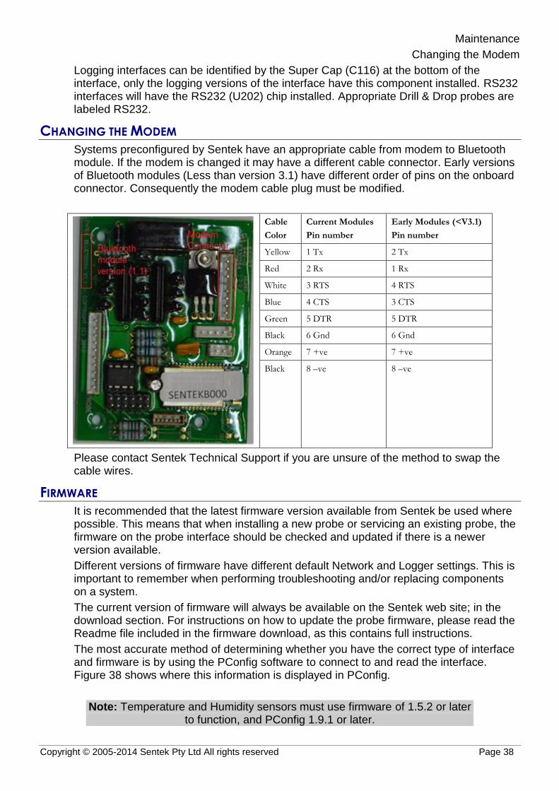
Maintenance
Changing the Modem
Copyright © 2005-2014 Sentek Pty Ltd All rights reserved Page 38
Logging interfaces can be identified by the Super Cap (C116) at the bottom of the interface, only the logging versions of the interface have this component installed. RS232 interfaces will have the RS232 (U202) chip installed. Appropriate Drill & Drop probes are labeled RS232.
CHANGING THE MODEM
Systems preconfigured by Sentek have an appropriate cable from modem to Bluetooth module. If the modem is changed it may have a different cable connector. Early versions of Bluetooth modules (Less than version 3.1) have different order of pins on the onboard connector. Consequently the modem cable plug must be modified.
Cable
Color
Current Modules
Pin number
Early Modules (<V3.1)
Pin number
Yellow 1 Tx 2 Tx
Red 2 Rx 1 Rx
White 3 RTS 4 RTS
Blue 4 CTS 3 CTS
Green 5 DTR 5 DTR
Black 6 Gnd 6 Gnd
Orange 7 +ve 7 +ve
Black 8 –ve 8 –ve
Please contact Sentek Technical Support if you are unsure of the method to swap the cable wires.
FIRMWARE
It is recommended that the latest firmware version available from Sentek be used where possible. This means that when installing a new probe or servicing an existing probe, the firmware on the probe interface should be checked and updated if there is a newer version available.
Different versions of firmware have different default Network and Logger settings. This is important to remember when performing troubleshooting and/or replacing components on a system.
The current version of firmware will always be available on the Sentek web site; in the download section. For instructions on how to update the probe firmware, please read the Readme file included in the firmware download, as this contains full instructions.
The most accurate method of determining whether you have the correct type of interface and firmware is by using the PConfig software to connect to and read the interface. Figure 38 shows where this information is displayed in PConfig.
Note: Temperature and Humidity sensors must use firmware of 1.5.2 or later to function, and PConfig 1.9.1 or later.

Maintenance
Firmware
Copyright © 2005-2014 Sentek Pty Ltd All rights reserved Page 39
Figure 38 Checking probe type and firmware versions
Appendix A – Modem information
Compatible Modems
Copyright © 2005-2014 Sentek Pty Ltd All rights reserved Page 40
APPENDIX A – MODEM INFORMATION
COMPATIBLE MODEMS
Sentek PLUS firmware version 1.2.3 and later have the ability to customise the various strings used to control the modem. As well as allowing certain parameters to be re-configured to suit the area in which a system is installed, this has the potential to allow any device that has a serial port and supports dial-up networking to be used with Sentek PLUS systems.
Sentek currently supplies and supports one modem for GPRS networks and one for Telstra’s NextG network and pre-configures Sentek PLUS interfaces for their use. The recommended modem specific settings for the probe can change and it should not be assumed that the settings in the probe interface are correct. Files which contain the most recently recommended settings can be downloaded from the Sentek website. For more information on how to restore these settings, see section Connecting External Antenna.
Sentek is not obliged to provide support for modems which it has not supplied or agreed to support.
SIM CARD PIN CODES
If the SIM card to be used in the modem is PIN locked, it can be unlocked using a mobile phone or by asking your provider to do so.
Alternatively, the Sentek PLUS interface may be set up to with the PIN in the Initialization string. This is the same as having to enter a PIN into a mobile phone when it is turned on, and gives some added security. To do this, when selecting the Network settings (.cfg) file to restore to the probe, select the file name which matches your modem and has the “PIN” identifier at the end of the file name (e.g. GPRS_NextG_SierraWireless_PIN.cfg). Then, in the Initialization string on the Network page, replace the “XXXX” with the four digit PIN that is locking the SIM. Write the changes to the probe.
For example;
Initialization string for a GPRS modem, with no SIM PIN enabled:
\T80000;|AT+CREG=2||\T9000;AT&D2|AT+CSQ|AT+CCED=0,1|AT+ADC?
With PIN enabled configuration file restored:
\T80000;|AT+CPIN=XXXX||AT+CREG=2||\T9000;AT&D2|AT+CSQ|AT+CCED=0,1|AT+ADC?
For SIM with PIN of “1234”:
\T80000;|AT+CPIN=1234||AT+CREG=2||\T9000;AT&D2|AT+CSQ|AT+CCED=0,1|AT+ADC?
Note: The response string would also need to change in this example, because after power up, the modem does not report the “+WIND: 4”
indication until after the PIN has been entered. So for the initialization process to begin, “+WIND: 1” must be added as an acceptable response.
USEFUL AT COMMANDS
Below is a list of modem commands and descriptions on how to use them. These are just a small selection of the possible modem commands, but have proven to be most useful for use in the Sentek PLUS and MULTI systems. For full lists of commands, please contact the modem manufacturers.

Appendix A – Modem information
Useful AT Commands
Copyright © 2005-2014 Sentek Pty Ltd All rights reserved Page 41
These commands can be sent to the modems in the PConfig program, by pressing Open Session, typing commands in the AT commands field and pressing Send. The sent commands and the modem responses will appear in the Modem Response field.
Note: Some NextG commands are specific to ETM9xxx Modems.
Table 2 Modem Commands
Command ETM9xxx Wavecom, Fastrack, Netcomm
Satellite Response
AT Yes Yes Yes Should return "OK"
AT+CSQ Yes Yes Yes* Shows the current signal strength and service quality in the form "+CSQ: 22, 0". The first number shows the signal strength. A result of 99 indicates no signal, anything else over 14 is good. This number can vary considerably, and two or three readings should be taken to get a good indication. Consistent results of 99, or below 10 may indicate antenna problems or other connection issues. The second number can be ignored.
AT+CPIN? Yes Yes N/A Shows the PIN status of the SIM card. A response of "READY" indicates that the PIN has been correctly entered, or the card is not PIN locked.
AT+CGDCONT? Yes Yes N/A Used to query the APN currently set in modem. Response should be in the form AT+CGDCONT=1,"IP","<APN>",0,0 A value of 1,"IP",,,0,0 indicated the APN has not been set.
AT+CGDCONT= 1,"IP","<APN>"
Yes Yes N/A Used to set the APN for your service provider. Where <APN> is replaced with your service provider’s APN. e.g. AT+CGDCONT=1,"IP","telstra.internet"
AT^SCFG= "Radio/Band"
Yes N/A N/A Used to query the frequency band on which the modem will operate. See set band command below.
AT^SCFG="Radio/Band",n
Yes N/A N/A Used to set the band on which the modem will operate. Where n has the following possibilities;
- auto select (from GSM 900, GSM 1800, WCDMA 2100 & WCDMA 850Mhz)
- UMTS 850Mhz (NextG)
- GSM 900
e.g. AT^SCFG="Radio/Band",127 See also section Extra Frequency Band information.
AT+WMBS? N/A Yes N/A Used to query the band on which the modem will operate. See set band command below.
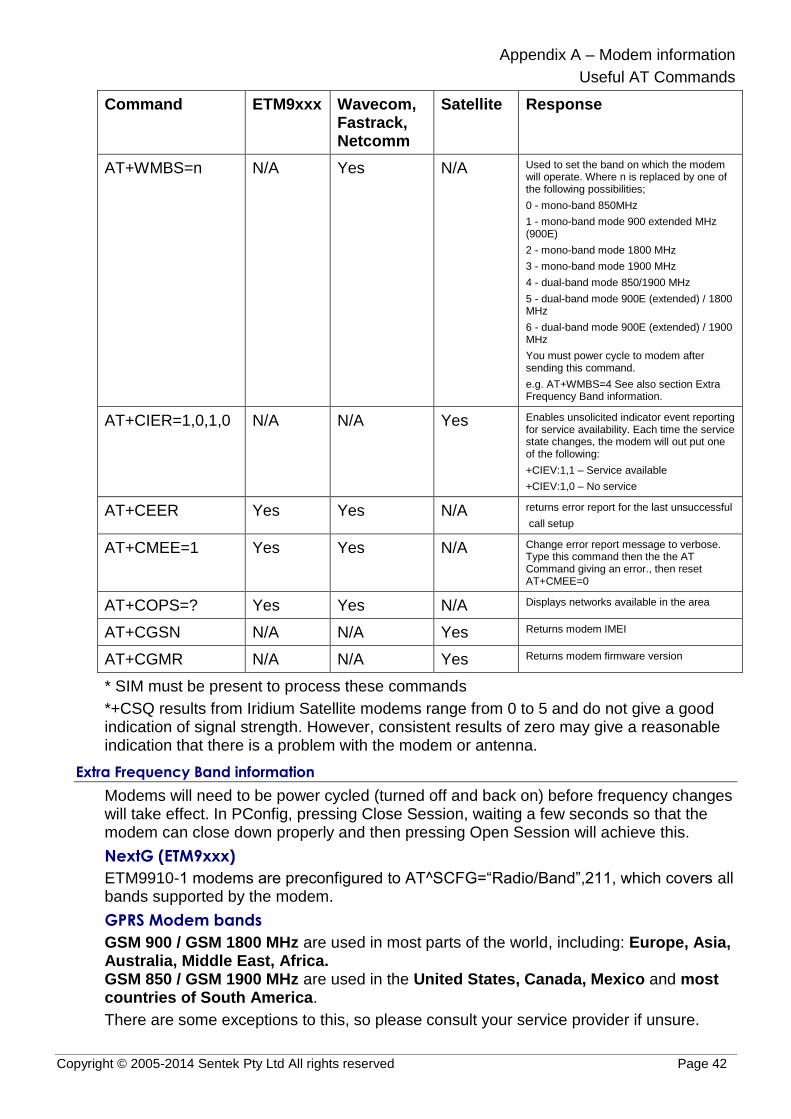
Appendix A – Modem information
Useful AT Commands
Copyright © 2005-2014 Sentek Pty Ltd All rights reserved Page 42
Command ETM9xxx Wavecom, Fastrack, Netcomm
Satellite Response
AT+WMBS=n N/A Yes N/A Used to set the band on which the modem will operate. Where n is replaced by one of the following possibilities;
0 - mono-band 850MHz
1 - mono-band mode 900 extended MHz (900E)
2 - mono-band mode 1800 MHz
3 - mono-band mode 1900 MHz
4 - dual-band mode 850/1900 MHz
5 - dual-band mode 900E (extended) / 1800 MHz
6 - dual-band mode 900E (extended) / 1900 MHz
You must power cycle to modem after sending this command.
e.g. AT+WMBS=4 See also section Extra Frequency Band information.
AT+CIER=1,0,1,0 N/A N/A Yes Enables unsolicited indicator event reporting for service availability. Each time the service state changes, the modem will out put one of the following:
+CIEV:1,1 – Service available
+CIEV:1,0 – No service
AT+CEER Yes Yes N/A returns error report for the last unsuccessful
call setup
AT+CMEE=1 Yes Yes N/A Change error report message to verbose. Type this command then the the AT Command giving an error., then reset AT+CMEE=0
AT+COPS=? Yes Yes N/A Displays networks available in the area
AT+CGSN N/A N/A Yes Returns modem IMEI
AT+CGMR N/A N/A Yes Returns modem firmware version
* SIM must be present to process these commands
*+CSQ results from Iridium Satellite modems range from 0 to 5 and do not give a good indication of signal strength. However, consistent results of zero may give a reasonable indication that there is a problem with the modem or antenna.
Extra Frequency Band information
Modems will need to be power cycled (turned off and back on) before frequency changes will take effect. In PConfig, pressing Close Session, waiting a few seconds so that the modem can close down properly and then pressing Open Session will achieve this.
NextG (ETM9xxx)
ETM9910-1 modems are preconfigured to AT^SCFG=“Radio/Band”,211, which covers all bands supported by the modem.
GPRS Modem bands
GSM 900 / GSM 1800 MHz are used in most parts of the world, including: Europe, Asia, Australia, Middle East, Africa. GSM 850 / GSM 1900 MHz are used in the United States, Canada, Mexico and most countries of South America.
There are some exceptions to this, so please consult your service provider if unsure.

Appendix A – Modem information
Useful AT Commands
Copyright © 2005-2014 Sentek Pty Ltd All rights reserved Page 43
Information sourced from worldtimezone.com, viewed at 26 July 2011, <http://www.worldtimezone.com/gsm.html>

Appendix B – Network page explained
Useful AT Commands
Copyright © 2005-2014 Sentek Pty Ltd All rights reserved Page 44
APPENDIX B – NETWORK PAGE EXPLAINED
Username and Password (Not used in Dial-in mode): These are for the GPRS or NextG network that the SIM card connects to – they are related to the APN server, not the FTP server. Many network providers allow these to be blank. For correct settings, contact your network provider.
The Command strings are used to control the modem during each stage of the Sentek PLUS system upload process. Sentek provides configuration files on the Sentek website to restore the network strings for modems sold by Sentek. Generally, the settings should not be altered from the default settings provided by Sentek in these files.
Dial-in Enable: In Dial-in mode, after every Sample Count interval has been reached the telemetry power is turned on and this string (up to 80 characters) is sent to the modem. The telemetry remains powered for the time specified in Dial-in Uptime, and then the Dial-in Disable string is sent. In normal (not Dial-in) mode, this string (up to 80 characters) is sent upon completion of an upload unless the Dial-in Uptime is set to zero – in this case, the dial-in feature is inactive.
This field can be used to command the modem to auto-answer incoming calls, for the uptime period, after the sample count scheduled time.
Dial-in Disable: In Dial-in mode, after a Dial-in Enable is sent, and when the end of the Dial-in Uptime has been reached, this string (up to 80 characters) is sent, and then the power is removed from the telemetry.
This field can be used to prevent the modem auto-answering incoming messages at times other than the sample count scheduled time. In normal (not Dial-in) mode, this string (up to 80 characters) is sent before starting an upload. The Dial-in Enable is sent at the completion of the upload. The telemetry remains powered for the time specified in Dial-in Uptime, and then the Dial-in Disable string is sent. If the Dial-in Uptime is zero the dial-in feature is inactive.
Init String: This string (up to 80 characters) configures the modem for communication, after it has been powered on.
Connect: (Not used in Dial-in mode) This string (up to 80 characters) supplied by your Network provider, is the command needed to connect to the network. It generally initiates the dialing of a specific telephone number.
Disconnect: (Not used in Dial-in mode) This string, up to 80 characters, is sent to the modem after the probe has sent the data to the network. It will disconnect the modem from the network.
Response(s): After being sent a command the modem replies with a response. If the specified response string is not received within the timeout period (\T…) set in the corresponding Network field, the probe will abandon communication until the next scheduled time. This includes responses that do not match the response string. The Dial-in Enable and Disable timeout is not dependent on the Connection Timeout value. A reply is considered matching when the start of the reply exactly matches the response string (up to 40 characters).

Appendix C – Upload Operation Diagram
Useful AT Commands
Copyright © 2005-2014 Sentek Pty Ltd All rights reserved Page 45
APPENDIX C – UPLOAD OPERATION DIAGRAM
Table 3 upload operation diagram
Sample
Origin
Upload Interval (Sample Count)
Begin next Upload
Interval (Sample Count)
Cannot Dial-in Dial-in Possible (Dial-In Delay)
Cannot Dial-in
Init
String
Connect
String
Connect
PPP
Connect
FTP
Upload
File(s)
Dis-
connect FTP
Dis-
connect PPP
Dis-
connect String
Power
Down 5 Sec
Init
String
Enable
String
Dial-in
Enabled
Disable
String
Power
Down 5 Sec
Many
Samples
Init
String
Sample(0) - This sample takes place a multiple number of Upload Intervals (Sample Counts) before
or after the Sample Origin (This example shows the upload at the origin)
Sample(1) - This indicates the earliest time that the next sample
can take place. If the sample interval is too short such that it falls into the area prior to Disconnecting from
the FTP server, then the sample will be missed causing
a gap in the data. If it is prior to the PowerDown state then the sample may delay the disconnect.
Sample
(Sample Count)
Sample(0)

Appendix D – PConfig Response Fields
Last Response
Copyright © 2005-2014 Sentek Pty Ltd All rights reserved Page 46
APPENDIX D – PCONFIG RESPONSE FIELDS
LAST RESPONSE
The Last Response shown on the Logger page of PConfig is the result of the last attempt by the probe to upload to the destination URL. This upload attempt can be a scheduled upload (triggered by the Sample Origin), or a user initiated Test or Upload from the Modem page of PConfig. See below for more detail on these Responses.
TEST/UPLOAD RESULT CODES
The 053 error in the example picture below was a result of the Connection Timeout period being reached before the connection to the FTP server was established (i.e. if the modem power cable was unplugged).
Figure 39 Upload result codes from most recent upload attempt
The table below shows a list of the response codes that may be seen during or after an upload attempt. The codes are separated into two sections; Progress codes indicate which stage of the upload process the probe is at. Upload response codes are used to show the result of an attempted upload.
Table 4 Last Response and uploading response codes
Code Message Detail Description
Progress codes
000 No Error Only occurs after first ever power on (No upload has been attempted)
001 Initializing Interface
Initialization and connect strings being sent
002 Initializing FTP Connecting to FTP server
003 Transferring Transferring data
004 Uploading to Server
Uploading file/s to FTP server
005 Disconnecting from Server
Disconnecting from FTP server, APN server and shutting down modem
006 Transfer Failure Satellite communication failed, attempting retry
Upload response codes.

Appendix D – PConfig Response Fields
Test/Upload Result Codes
Copyright © 2005-2014 Sentek Pty Ltd All rights reserved Page 47
040 Success Upload was successful (file transferred to FTP server)
041 Success (No Data) No new data to upload
042 User Cancel Pressed Cancel in PConfig
043 043 Success WARNING: Clock needs to be synchronized. Probe clock has not been set. Uploaded data will have a date of 2000/01/01.
051 Clock Not Set Clock needs to be reset (modify date and time or Synchronize with Computer and Write to probe)
053 Connection Failure
Modem not responding to commands, or could not connect to internet (see note below)
054 Server Error Problem communicating with FTP server
055 Internal Error Corrupt file in probe memory. Need to clear memory (Delete Readings).
056 Front Panel Active Attempt to perform modem function while connected through Dial-in or Front Panel
057 Supply voltage too low
Voltage below Telemetry Disable voltage level
058 Invalid URL Destination URL invalid
060 Satellite Error Could not communicate with satellite. Check antenna and registration of the satellite modem.
061 Transfer Failure Lost communication with satellite. Will be retried at next sample time
063 Transfer Timeout Lost communication with satellite. Will be retried at next sample time
080 Modem In Use Cannot do an Open session from front panel.
081 Deferred Upload Upload will commence when PConfig/Android App is disconnected. Reconnect after 3 minutes (180 seconds) and check Last Response for 040 Success.
Note: If test upload fails with the error “053 Connection Failure: "Error timeout" [Connect Modem]”, go to the Network tab of the Probe Configuration Utility and check the Initialization string. It should begin with “\T” followed by a number. This number indicates the time in milliseconds that the interface will wait for the initial modem response. Increasing it may correct this error – for example, changing it from “\T30000” to “\T60000”.

Appendix D – PConfig Response Fields
Upload log
Copyright © 2005-2014 Sentek Pty Ltd All rights reserved Page 48
Note: If test upload fails with the error “053 Connection Failure: "Error timeout" [Connect Modem]”, it could be caused by the probe not seeing any of the acceptable responses within the timeout period set at the beginning of
the Initialisation string (see section Network page).
In PConfig, measure the time it takes after clicking Open Session for each message to appear in the Modem Response field. The timeout at the
beginning of the Initialisation string should exceed the time it takes for the first expected response to appear.
For example; the first expected response could be “+WIND: 4”, and this commonly takes anywhere from 15 to 40 seconds to appear after modem
power up. So the initialization string should start with “\T50000;|”. This would mean that the modem has 50 seconds to display the +WIND: 4, if it’s seen the probe continues through to the Initialization string. If it takes longer than 50 seconds (or doesn’t appear at all), the probe will timeout and abort the
attempt.
UPLOAD LOG
It is possible to retrieve from the probe, a log of the codes from the last upload attempt. Only the information from the previous upload test, whether it was a scheduled upload or user initiated Test, is kept in the log. To retrieve the logged upload information from the probe;
1. Connect to the probe in the PConfig software.
2. Go to the Modem page of PConfig
3. Press Open Session
4. Wait until the modem has finished sending the Unsolicited Result Codes and then, using the AT Commands field, send the command below:
\showdetails
The log information should be displayed in the Modem Response field. Copy all text in this field into a text editor program (i.e. Notepad). Save the information.
This manual does not attempt to explain how to interpret the \showdetails information. Sentek Distributors can send a copy of the response to Sentek for interpretation and troubleshooting help.

Appendix E - Technical Specifications
EnviroSCAN Series II 232 interface
Copyright © 2005-2014 Sentek Pty Ltd All rights reserved Page 49
APPENDIX E - TECHNICAL SPECIFICATIONS
ENVIROSCAN SERIES II 232 INTERFACE
PCB Revision: REV 2.4
Identification Label: XPI-SC-E-RS232
Interface connector type: Brand: Phoenix Contact
MC 1,5/8-ST-3,5 (Plug)
MC 1,5/8-G-3,5 (Socket)
RS232 Interface pin configuration:
1. +Vin
2. +Vin(T)
3. +Vout(T)
4. Ground
5. TX – RS232 Data
6. RX– RS232 Data
7. Request to send (RTS acts as DTR in the Plus systems)
8. Clear to Send (CTS)
Voltage Supply (RS232 +Vin): 4 – 15 Volts (12 V DC @ >200mA recommended)
Fuse specifications: F201 Vin (300mA) Resettable (not replaceable)
F202 Vout (1.1A) Resettable (not replaceable) (Both remain open circuit while the fault condition exists)
Output port baud rate: 9600 bits per second
TTL Interface connector type: Brand: JST
B 6B-PH-K (Socket)
PHR- 6 (Plug), SPH-002T-P0.5S (Crimp connectors)
TTL Interface pin configuration:
1. +Vcc
2. Transmit data (Tx)
3. Receive data (Rx)
4. Reserved
5. Reserved
6. Ground
Voltage Supply (TTL +Vcc): 5 Volts, supplied by the EnviroSCAN probe interface
TTL baud rate: 1200, 2400, 9600 (default), 19200 and
38400 bits/second (user configurable)

Appendix E - Technical Specifications
EnviroSCAN Series II 232 interface
Copyright © 2005-2014 Sentek Pty Ltd All rights reserved Page 50
Total current consumption: 400µA standby @ 12V DC
105mA sampling (Moisture) @ 12V DC
130mA Sampling (TriSCAN) @ 12V DC
Time to sample 1 sensor: 45 milliseconds maximum (Moisture only)
90 milliseconds maximum (TriSCAN)
Maximum sensors supported: 16 Moisture Sensors or
16 TriSCAN Sensors and
16 Temperature Humidity sensors
Figure 40 EnviroSCAN RS232 probe interface board layout

Appendix F - Glossary of Terms
EnviroSCAN Series II 232 interface
Copyright © 2005-2014 Sentek Pty Ltd All rights reserved Page 51
APPENDIX F - GLOSSARY OF TERMS
3G Third Generation mobile phone network
All-in-One All-in-One Probe
BW Bandwidth, the amount of traffic allowed in a set period
CDMA Code Division Multiple Access (Used by selected Modems)
Domain name Name given to web location e.g. www.sentek.com.au
DTU Data Transmission Unit (housing containing modem, battery and solar charger board)
FQDN Fully qualified domain name
FTP File Transfer Protocol – used to upload / download files
GPRS General Packet Radio Service (Used by selected Modems)
Host Web site / data storage provider
HTTP Hyper Text Transfer Protocol - Used to download files
IP Address Internet Protocol address – Numbered address of host
NextG Telstra Australia implementation of 3G
PIN Personal Identification Number
SIM Card Subscriber Identity Module, required for GSM/GPRS/NextG Access
Storage Capacity
Available space on server to store data files
URL Universal Resource Locator


Appendix G - Configuring the Probe using Bluetooth on a Laptop
EnviroSCAN Series II 232 interface
Copyright © 2005-2014 Sentek Pty Ltd All rights reserved Page 53
APPENDIX G - CONFIGURING THE PROBE USING BLUETOOTH ON A LAPTOP
Note: While the Bluetooth module is active an internal buzzer sounds.
Every All-in-One probe or Compact DTU has a unique Bluetooth identifier which, when configured in Windows, has its own COM port. This identifier e.g. "SENTEKB00205" is shown on the compliance label on the All-in-One top cap. Once configured, the device is shown in the Devices list and it has an associated COM port.
When the COM port is known, you can run PConfig without going through the configuration steps e.g.
The device remains in the list of devices until it is deleted. It is not necessary to delete it unless the number of devices becomes unmanageable.
The following steps describe configuring the Bluetooth device and finding its COM port.
1. If the Sentek Device is already installed, for this serial number, it will appear in the list of Bluetooth Devices. There is no need to follow these steps. If the list gets too long, select unwanted Sentek devices and press Delete. Step 7 shows how to get the COM port if you did not take a note of COM number.
2. Select windows menu option for Devices
a) Windows XP, 7 and Vista - Devices and Printers or
b) Windows 8 - Settings > change PC Settings (or Control Panel > Hardware and Sound
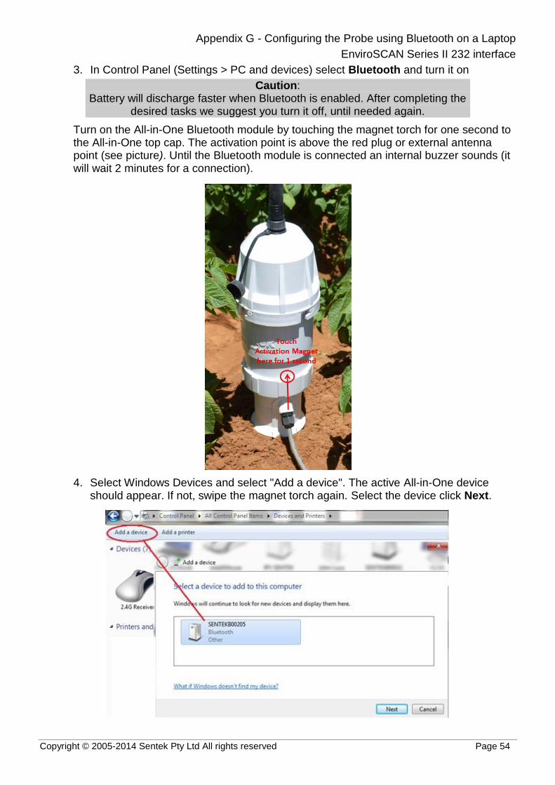
Appendix G - Configuring the Probe using Bluetooth on a Laptop
EnviroSCAN Series II 232 interface
Copyright © 2005-2014 Sentek Pty Ltd All rights reserved Page 54
3. In Control Panel (Settings > PC and devices) select Bluetooth and turn it on
Caution: Battery will discharge faster when Bluetooth is enabled. After completing the
desired tasks we suggest you turn it off, until needed again.
Turn on the All-in-One Bluetooth module by touching the magnet torch for one second to the All-in-One top cap. The activation point is above the red plug or external antenna point (see picture). Until the Bluetooth module is connected an internal buzzer sounds (it will wait 2 minutes for a connection).
4. Select Windows Devices and select "Add a device". The active All-in-One device should appear. If not, swipe the magnet torch again. Select the device click Next.

Appendix G - Configuring the Probe using Bluetooth on a Laptop
EnviroSCAN Series II 232 interface
Copyright © 2005-2014 Sentek Pty Ltd All rights reserved Page 55
5. Select the "Enter the Device's Pairing" code click Next and enter the Pairing code "1234" and click Next.
6. The device is now available click Close
7. In the device list, right click on the Bluetooth device and select Properties. In properties check the Serial port checkbox and take a note of the port number for use by PConfig. Click OK.
8. Your laptop now has a Bluetooth port that can be used by PConfig. Using the port number discovered in the previous step.

Appendix G - Configuring the Probe using Bluetooth on a Laptop
EnviroSCAN Series II 232 interface
Copyright © 2005-2014 Sentek Pty Ltd All rights reserved Page 56
9. Additionally you can also use Data Exchange to download data from the source module "Sentek PLUS/Multi/Solo (Cable)".
,

Appendix H - Sentek PLUS Quick Reference Guide
Product Set-up Checklist
Copyright © 2005-2014 Sentek Pty Ltd All rights reserved Page 57
APPENDIX H - SENTEK PLUS QUICK REFERENCE GUIDE
This appendix is designed to be a short guide for installers of Sentek All-in-One. It can be printed and carried into the field and act as a reminder for the basic steps needed to install and troubleshoot a complete Sentek All-in-One system. It does not replace the manual, it merely supplements it.
PRODUCT SET-UP CHECKLIST
Preparation
1. Select probe and sites. Test signal strengths and decide on system configuration.
2. Organise data transmission and hosting, as detailed in Sentek All-in-One Hardware Manual section Data Transfer and Hosting.
3. Using PConfig, for each probe;
Check that the interface has the latest version of firmware
Configure sensors (Auto-detect, set depths & normalise)
Set Clock (Time & sampling interval)
Configure Modem Settings (Restore network configuration which matches modem being used)
Check system (Test)
(For further information, refer to Sentek All-in-One hardware manual and PConfig Help)
Warning: Do not leave the 14V battery connected in the housing during transportation
or damage may occur
Field Installation
1. Install access tubes as per the Sentek Access Tube Installation Guides (Screw Cap), and as demonstrated during official Sentek training.
a) Screw Bottom plastic onto Top cap
b) Insert probe rod.
c) Plug All-in-One internal plastic into the top of probe rod.
d) Connect external antenna if required.
e) Ensure the Pink O-ring in All-in-One top cap has a good coating of Silicon Grease.
f) Place cap on bottom plastic, rotate counter clockwise until the Pins are seated all the way down the end of the slot in the cap.
Software
Allow probe time to upload readings to the server.
1. Enter the server details into Data Exchange (Edit Server).
2. For each probe, use the New Database Wizard and Download Wizard within an IrriMAX workspace to set up new databases and associated downloads.
3. Create graphs, save the workspace and create a batch file to run the downloads.
Example Batch File: “Path to IrriMax.exe" "path to workspace.sws" /DOWNLOAD

Troubleshooting Guide
Copyright © 2005-2014 Sentek Pty Ltd All rights reserved Page 58
TROUBLESHOOTING GUIDE
As All-in-One probes are preconfigured before delivery, only user controlled capabilities should be addressed in the field.
Any problem that cannot be resolved should be directed to your distributor.
Once a problem has been flagged, troubleshooting should be carried out in this order:
1. Download all data and review graphs, looking at all sensors for problem symptoms and causes.
2. Before picking up any tools, moving cables or altering the system in any way, connect to the probe in PConfig and identify what the current fault is. If you miss this step, you will not know whether you have fixed the original problem or not.
Tip: Upload readings and back up probe configuration before changing any probe settings.
3. Using Table 5 below as a starting point, begin finding the cause of the fault. Change only one thing at a time and then check to see if it has changed the original symptom of the fault. Try something else if the symptom has not changed.
4. Once the cause and symptom have been found and rectified, test all sensors and upload operation in PConfig. If a new symptom appears, start again at step 2.
Table 5 Troubleshooting
Symptom/Error Message
Possible Cause of Failure Check Possible Solution
Cannot connect with any device
Connectors not seated in the sockets
Bluetooth module securely seated to interface
Ensure module screwed to interface
Battery not connected Battery plug Ensure battery plugs clicked together
Cannot connect to probe with PConfig through TTL connection
Wrong COM Port selected in PConfig
Check COM Port number in Windows Device Manager
Ensure cable drivers are installed and correct COM port is selected
Low power supplied to interface Measure DC voltage at interface connector
Replace battery if not 14V
Replace corroded wires or connectors
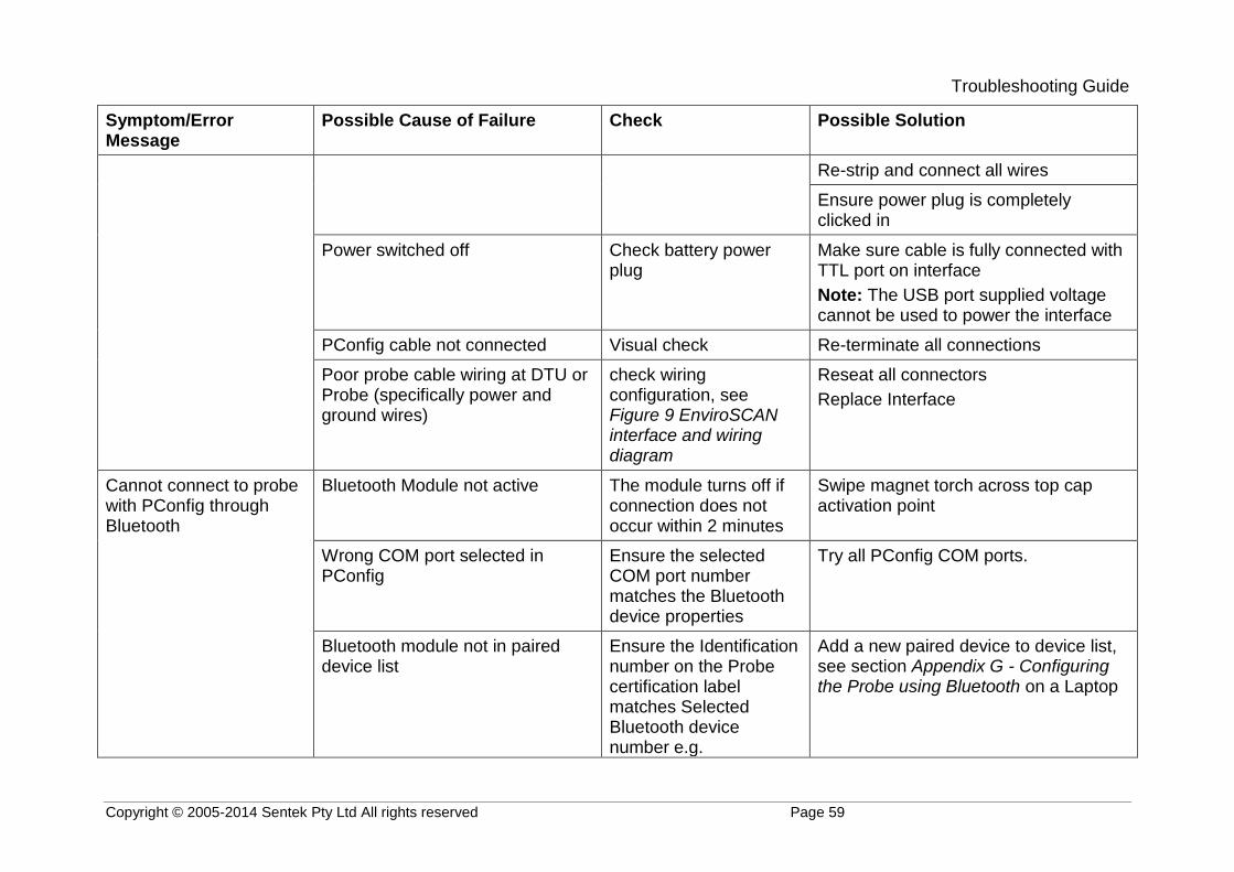
Troubleshooting Guide
Copyright © 2005-2014 Sentek Pty Ltd All rights reserved Page 59
Symptom/Error Message
Possible Cause of Failure Check Possible Solution
Re-strip and connect all wires
Ensure power plug is completely clicked in
Power switched off Check battery power plug
Make sure cable is fully connected with TTL port on interface
Note: The USB port supplied voltage cannot be used to power the interface
PConfig cable not connected Visual check Re-terminate all connections
Poor probe cable wiring at DTU or Probe (specifically power and ground wires)
check wiring configuration, see Figure 9 EnviroSCAN interface and wiring diagram
Reseat all connectors
Replace Interface
Cannot connect to probe with PConfig through Bluetooth
Bluetooth Module not active The module turns off if connection does not occur within 2 minutes
Swipe magnet torch across top cap activation point
Wrong COM port selected in PConfig
Ensure the selected COM port number matches the Bluetooth device properties
Try all PConfig COM ports.
Bluetooth module not in paired device list
Ensure the Identification number on the Probe certification label matches Selected Bluetooth device number e.g.
Add a new paired device to device list, see section Appendix G - Configuring the Probe using Bluetooth on a Laptop

Troubleshooting Guide
Copyright © 2005-2014 Sentek Pty Ltd All rights reserved Page 60
Symptom/Error Message
Possible Cause of Failure Check Possible Solution
SENTEKB00205
Cannot connect to probe with Android App
Bluetooth Module not active The module turns off if connection does not occur within 2 minutes
Swipe magnet torch across top cap activation point
Not connecting to correct probe Device is in the Scan for devices list
If paired device the device identification number matches the probe's number e.g. SENTEKB00205
Exit App and try again.
See section Verifying Probe Configuration with Sentek Android App
See Android Probe Utility App User Guide
Failure of Modem “Test” upload
Modem not powering with Open session in PConfig
Should be 14V at Pin 3 (brown wire) on interface
Replace probe cable (if power is ok at interface)
Monitor battery voltage while modem active (modem light is on or flashing)
Replace battery if it drops below 14V
Probe not configured to match modem type
Download Network settings .cfg files from Sentek web site and restore correct file to probe
Last Response “053 Connection Failure [Connect Modem]”
Probe not configured to match modem type
Download Network settings .cfg files from Sentek web site and restore correct file to probe

Troubleshooting Guide
Copyright © 2005-2014 Sentek Pty Ltd All rights reserved Page 61
Symptom/Error Message
Possible Cause of Failure Check Possible Solution
Last Response “053 Connection Failure "or "058 Invalid URL"
Upload Internet URL is your assigned web location
Ensure you have the correct ftp://<user name>:<password>@<host/Internet address>/<url-path>
Last Response other values See Table 4 Last Response and uploading response codes
Follow suggestions in the table.
Antenna not connected Check that antenna is cabled to modem
Tighten antenna connectors
Poor signal strength Use \showdetails to check the signal strength parameter CSQ
See section Upload log
Replace internal antenna with external antenna
Data uploaded does not show expected (correct) time
Probe Clock incorrect Connect using Android App or PConfig Clock tab and check probe time
Select option to Synchronize with Computer
Invalid sensor data (0 raw counts), but voltage readings ok
Interface or sensor pins not all in their socket
All connectors Reseat top cap plug
Reseat sensor plugs
Probe not logging one or more sensors
Sensor depth(s) = 0 or Salinity air and water values not normalized (still 65535, 0)
Configuration tab in PConfig
Use PConfig to set depths and Normalize or restore configuration from previously save Backup Configuration.
Sample Origin in the future Logger tab in PConfig Set Oringin date in the past.

Recommended Maintenance Schedules
Copyright © 2005-2014 Sentek Pty Ltd All rights reserved Page 62
RECOMMENDED MAINTENANCE SCHEDULES
Daily
Use IrriMAX graph to review battery voltage (V1, V2) profile and replace battery when battery voltage shows signs of degradation
6 months (or each time access tube is opened)
Check probe and access tube for moisture
Replace silica gel bag
12 months
Check for dust and/or water ingress into All-in-One housing
Check cable for damage to outer sheath and wires
Check antenna is secured tightly
Ensure all cables are neat
Clean SIM contacts
Replace 14V battery
3 years
Replace All-in-One top cap


