Semi-Automated Needle Steering in Biological Tissue Using ...
14
Semi-Automated Needle Steering in Biological Tissue Using an Ultrasound-Based Deflection Predictor MOHSEN KHADEM 1 CARLOS ROSSA, 1 NAWAID USMANI, 2 RON S. SLOBODA, 2 and MAHDI TAVAKOLI 1 1 Department of Electrical and Computer Engineering, University of Alberta, Edmonton, AB T6G 1H9, Canada; and 2 The Cross Cancer Institute and the Department of Oncology, University of Alberta, Edmonton, AB T6G 1Z2, Canada Abstract—The performance of needle-based interventions depends on the accuracy of needle tip positioning. Here, a novel needle steering strategy is proposed that enhances accuracy of needle steering. In our approach the surgeon is in charge of needle insertion to ensure the safety of operation, while the needle tip bevel location is robotically controlled to minimize the targeting error. The system has two main components: (1) a real-time predictor for estimating future needle deflection as it is steered inside soft tissue, and (2) an online motion planner that calculates control decisions and steers the needle toward the target by iterative optimization of the needle deflection predictions. The predictor uses the ultrasound-based curvature information to estimate the needle deflection. Given the specification of anatomical obstacles and a target from preoperative images, the motion planner uses the deflection predictions to estimate control actions, i.e., the depth(s) at which the needle should be rotated to reach the target. Ex-vivo needle insertions are performed with and without obstacle to validate our approach. The results demonstrate the needle steering strategy guides the needle to the targets with a maximum error of 1.22 mm. Keywords—Medical robotics, Needle steering, Motion plan- ning, Homotopy analysis method. INTRODUCTION Robotics-assisted needle adjustment can be used to steer the needle inside the tissue and enhance accuracy of percutaneous needle insertions. The term ‘‘needle steering’’ implies control of the needle tip deflection and changing the direction of the needle tip trajectory as the needle is being inserted by means of inputs such as needle insertion velocity, lateral manipulation of the needle base, or axial rotation of the beveled-tip needle 3 (see Fig. 1). Modeling of needle-tissue interaction makes it pos- sible to steer flexible needles from outside the body to reach specified targets inside the body. Prediction of the needle deflection in soft tissue has been the topic of significant research efforts. 8,14,22,25 Webster et al. developed a nonholonomic kinematics-based model for steering flexible bevel-tipped needles. 25 The model assumes that the needle tip trajectory has a constant radius of curvature. Goksel et al. developed three dif- ferent needle models based on beam theories. 5 Yan et al. modelled needle interaction with the tissue as a beam connected to a series of springs. 26 Misra et al. used an energy-based formulation for a beam that is in contact with a nonlinear hyperplastic tissue to simulate needle steering. 14 From our group, Khadem et al. used a dynamic beam theory to develop a model relating needle tip position to insertion velocity. 8 The nonholonomic kinematic model has been widely used for developing needle steering strategies and controlling needle deflection. Roesthuis et al. modified the model by accounting for the tissue cutting angle and used the model for control of the needle deflection. 19 Rucker et al. proposed a sliding mode control method based on the kinematics-based model. 21 Employing the well-known kinematics-based model, researchers have shown that the curvature of the needle path can be controlled through duty-cycled spinning of the needle during insertion. 12 Using duty- cycling, the needle deflection curvature is related to the insertion velocity. 16 Vrooijink et al. developed a needle steering system that uses 2D ultrasound images to estimate the needle pose and an RRT motion planner that computes a feasible needle path toward the target based on the needle pose estimation. 23 Khadem et al. Address correspondence to Mohsen Khadem, Department of Electrical and Computer Engineering, University of Alberta, Edmonton, AB T6G 1H9, Canada. Electronic mail: mohsen. [email protected] This paper appear in Annals of Biomedical Engineering Content may change prior to publication DOI: 10.1007/s10439-016-1736-x
Transcript of Semi-Automated Needle Steering in Biological Tissue Using ...

Semi-Automated Needle Steering in Biological Tissue Using
an Ultrasound-Based Deflection Predictor
MOHSEN KHADEM ,1 CARLOS ROSSA,1 NAWAID USMANI,2 RON S. SLOBODA,2 and MAHDI TAVAKOLI1
1Department of Electrical and Computer Engineering, University of Alberta, Edmonton, AB T6G 1H9, Canada; and 2The CrossCancer Institute and the Department of Oncology, University of Alberta, Edmonton, AB T6G 1Z2, Canada
(Received 18 May 2016; accepted 12 September 2016)
Associate Editor Xiaoxiang Zheng oversaw the review of this article.
Abstract—The performance of needle-based interventionsdepends on the accuracy of needle tip positioning. Here, anovel needle steering strategy is proposed that enhancesaccuracy of needle steering. In our approach the surgeon is incharge of needle insertion to ensure the safety of operation,while the needle tip bevel location is robotically controlled tominimize the targeting error. The system has two maincomponents: (1) a real-time predictor for estimating futureneedle deflection as it is steered inside soft tissue, and (2) anonline motion planner that calculates control decisions andsteers the needle toward the target by iterative optimizationof the needle deflection predictions. The predictor uses theultrasound-based curvature information to estimate theneedle deflection. Given the specification of anatomicalobstacles and a target from preoperative images, the motionplanner uses the deflection predictions to estimate controlactions, i.e., the depth(s) at which the needle should berotated to reach the target. Ex-vivo needle insertions areperformed with and without obstacle to validate ourapproach. The results demonstrate the needle steeringstrategy guides the needle to the targets with a maximumerror of 1.22 mm.
Keywords—Medical robotics, Needle steering, Motion plan-
ning, Homotopy analysis method.
INTRODUCTION
Robotics-assisted needle adjustment can be used tosteer the needle inside the tissue and enhance accuracyof percutaneous needle insertions. The term ‘‘needlesteering’’ implies control of the needle tip deflectionand changing the direction of the needle tip trajectoryas the needle is being inserted by means of inputs suchas needle insertion velocity, lateral manipulation of the
needle base, or axial rotation of the beveled-tip needle3
(see Fig. 1).Modeling of needle-tissue interaction makes it pos-
sible to steer flexible needles from outside the body toreach specified targets inside the body. Prediction ofthe needle deflection in soft tissue has been the topic ofsignificant research efforts.8,14,22,25 Webster et al.developed a nonholonomic kinematics-based modelfor steering flexible bevel-tipped needles.25 The modelassumes that the needle tip trajectory has a constantradius of curvature. Goksel et al. developed three dif-ferent needle models based on beam theories.5 Yanet al. modelled needle interaction with the tissue as abeam connected to a series of springs.26 Misra et al.used an energy-based formulation for a beam that is incontact with a nonlinear hyperplastic tissue to simulateneedle steering.14 From our group, Khadem et al. useda dynamic beam theory to develop a model relatingneedle tip position to insertion velocity.8
The nonholonomic kinematic model has beenwidely used for developing needle steering strategiesand controlling needle deflection. Roesthuis et al.modified the model by accounting for the tissue cuttingangle and used the model for control of the needledeflection.19 Rucker et al. proposed a sliding modecontrol method based on the kinematics-basedmodel.21 Employing the well-known kinematics-basedmodel, researchers have shown that the curvature ofthe needle path can be controlled through duty-cycledspinning of the needle during insertion.12 Using duty-cycling, the needle deflection curvature is related to theinsertion velocity.16 Vrooijink et al. developed a needlesteering system that uses 2D ultrasound images toestimate the needle pose and an RRT motion plannerthat computes a feasible needle path toward the targetbased on the needle pose estimation.23 Khadem et al.
Address correspondence to Mohsen Khadem, Department of
Electrical and Computer Engineering, University of Alberta,
Edmonton, AB T6G 1H9, Canada. Electronic mail: mohsen.
Annals of Biomedical Engineering (� 2016)
DOI: 10.1007/s10439-016-1736-x
� 2016 Biomedical Engineering Society
This paper appear in Annals of Biomedical Engineering Content may change prior to publication DOI: 10.1007/s10439-016-1736-x

used the mechanics-based model and developed animage-guided model predictive controller for 2D nee-dle steering.7 Moreira et al. developed an experimentalmodel of needle curvature as a function of tissuestiffness by fitting an exponential curve to experimentaldata. The model was capable of simulating non-con-stant deflection curvature and was used for fully ro-botic needle insertion.15
The performance of model-based controllers highlyrelies on accurate models for precise needle positionprediction. The widely used kinematic model assumesthat as the needle is inserted, it moves on a constantcurvature path, which is not always the case.13 Previ-ous studies have shown that when the kinematic modelis applied to path planning and control in soft tissues,there are non-negligible deviations between the modeland experimental data due to tissue inhomogeneity oruncertainty in the nominal values of the modelparameters.18 Also, the needle tip deflection dependson the insertion velocity. Thus, the accuracy of thekinematics-based model, identified for a fixed insertionvelocity, decreases as the insertion velocity is increased.Also, all the previous studies have only considered thefully robotic needle insertion.1,7,11,16,23 In fully roboticneedle steering the goal is to calculate a needle steeringcontrol input (mainly needle axial rotation) assumingthe rest of the inputs are fixed at known values suchthat needle targeting accuracy is improved. A possibleintermediate step between manual and fully-roboticinsertion is semi-manual needle insertion, in whichautomatic robot-assisted adjustments are performed toone of the control inputs while other inputs are directlyapplied by the surgeon. For instance, the surgeon is incharge of needle insertion in the interest of ensuring thesafety of the operation and to maintain continuousengagement, while the needle tip bevel location iscontrolled robotically.
Objective and Contribution
In this paper, we propose a novel semi-automatedstrategy for steering needles in soft tissue, which can beused to target a specific point and maneuver the needletip around an obstacle. Other contributions of thispaper include: (1) an adaptive real-time needle deflec-tion predictor developed using the homotopy analysismethod (HAM). The predictor accounts for 180� nee-dle axial rotations and changes in the needle deflectionradius of curvature due to factors such as tissueinhomogeneity and varying insertion velocity. (2) Anovel online motion planner that is informed by thepredictions of the HAM-based predictor and auto-matically rotates the needle while the needle is manu-ally inserted to reach the desired target. The planner isalso used to maneuver the needle tip around anobstacle, which extends the use of needle-based inter-ventions to deeper or more difficult-to-reach targets.
MATERIALS AND METHODS
In this section, the details of the proposed semi-automated needle steering strategy are presented. Thisincludes the derivation of the equations for the HAM-based needle deflection predictor, the method pro-posed for ensuring rapid convergence of the predic-tions, and the online needle motion planner forsteering needle in soft tissue.
HAM-Based Needle Deflection Prediction
HAM is a mathematical technique to solve nonlin-ear ordinary/partial differential equations.10 Thismethod is based on the concept of homotopy, a fun-damental concept in topology and differential geome-try. A homotopy describes a continuous variation or
FIGURE 1. (a) A schematic of needle insertion in brachytherapy. The surgeon inserts long flexible needles through the patient’sperineum in order to deliver radioactive seeds within the prostate gland. The uneven distribution of forces at the asymmetricbeveled tip of the needle causes the needle to deflect from a straight path during the insertion. (b) A schematic of needle and inputsused to control needle deflection including needle insertion velocity, lateral manipulation of the needle base, tissue manipulation,and changing the orientation of the beveled tip by axially rotating the needle.
KHADEM et al.

deformation. For instance, a circle can be continuouslydeformed into an ellipse. Such a deformation is called ahomotopy between the two functions describing thecircle and the ellipse. We will use the concept of HAMto estimate the continuous deformation of needle as itis being inserted into the tissue.
First, we assume that the needle curvature belongsto a certain homotopy. Next, we develop the equationsgoverning the deformation of the homotopy. Finally,real-time visual feedback from the ultrasound imagesare used to select the best curve from the homotopyand use that to predict the needle deflections in futuresteps. A brief introduction to the HAM is presented inthe following.
Let us consider a nonlinear differential equation
N ½yðxÞ� ¼ fðxÞ;B½y; y0� ¼ 0 ð1Þ
N is a nonlinear operator that represents a nonlinearequation, x denotes the independent variable, primedenotes differentiation with respect to x, yðxÞ is anunknown function, fðxÞ is a known analytic function,and B is a boundary operator defining the boundaryconditions. By means of the homotopy method onecan construct the so-called zero-order deformationequation as
ð1� qÞL½yðxÞ � y0ðxÞ� ¼ c0q N ½yðxÞ� � fðxÞ½ � ð2Þ
where q 2 ½0; 1� is the homotopy parameter, c0 6¼ 0 is aconvergence-control parameter, L is an auxiliary linearoperator, and y0ðxÞ is the initial guess of yðxÞ. One hasgreat freedom to choose the auxiliary linear operator Lin HAM.9 From (2), we have
yðxÞ ¼ y0ðxÞ when q ¼ 0
N½yðxÞ� ¼ fðxÞ when q ¼ 1ð3Þ
Thus, as q increases from 0 to 1, the homotopy con-tinuously deforms from the initial guess to the solutionof the original nonlinear equation in (1). So, thesolution yðxÞ depends on the homotopy parameter andcan be expressed more accurately as yðx; qÞ. Expandingyðx; qÞ using Maclaurin series with respect to q, onehas
yðx; qÞ ¼ y0ðxÞ þXþ1
n¼1
ynðxÞqn ð4Þ
where
ynðxÞ ¼ Dn½yðx; qÞ� ¼1
n!
@nyðx; qÞ@qn
����q¼0
ð5Þ
Dn½�� is called the nth-order homotopy derivativeoperator. The series in (4) converges at q ¼ 1. Then wehave the mth-order homotopy-approximation of thesolution to the nonlinear equation as
yðxÞ � y0ðxÞ þXm
n¼1
ynðxÞ ð6Þ
In order to calculate ynðxÞ (n ¼ 1; . . . ;m) in (6), wedifferentiate (4) n times with respect to q. Then divid-ing by n! and setting q ¼ 0, we get the nth-orderdeformation equation
L½ynðxÞ � vnyn�1ðxÞ� ¼ c0Dn�1 N ½yðxÞ� þ ð1� vnÞfðxÞ½ �ð7Þ
where
vnðxÞ ¼0; if n � 11; if n>1
�ð8Þ
ynðx; tÞ (for n � 1) in (7) is linear with linearboundary conditions that come from the originalproblem and can be easily solved in real-time. Using(7) one can successively obtain homotopy approxi-mation of the solution of the nonlinear differentialequation in (1).
Now we use the HAM for predicting needledeflection. Let us assume j is the signed curvature ofthe needle tip trajectory and x is the insertion depth. Ifthe needle deflection is given in Cartesian coordinatesas yðxÞ, then from basic geometry we have
j ¼ y00ðxÞð1þ y02ðxÞÞ
32
ð9Þ
During insertions, the ultrasound probe acquirestransverse images of the needle tip (see Fig. 1a). Weuse the method presented by Wain et al. to estimatethe needle tip trajectory and its curvature (j) from theultrasound images.24 The sign of j corresponds to theneedle tip orientation and changes after each 180�axial rotation of the needle. Having an approximationof the curvature, using (9) we can define the generalnth-order deformation equation governing the defor-mation of the needle and use the HAM method tocalculate the needle tip deflection. We can rewrite (9)as
N½yðxÞ� : ¼ y002ðxÞ � sgnðjÞj2½3y02ðxÞ þ 3y04ðxÞþ y06ðxÞ� ¼ sgnðjÞj2
ð10Þ
subject to the initial conditions
yð0Þ ¼ Y0; y0ð0Þ ¼ Y00 ð11Þ
where sgnð�Þ is the sign function. Y0 is the initialdeflection of the needle tip and Y0
0 is the first derivative
of the needle deflection, both evaluated at x ¼ 0. Y00
corresponds to the initial angle of the needle tip withrespect to the insertion axis. Y0 is equal to zero at the
Semi-Automated Needle Steering in Biological Tissue

beginning of the insertion. However, after each needlerotation it is updated to the needle tip deflectionimmediately prior to rotation. The same approach isused for Y0
0.
To solve (10) and (11) by means of the homotopyanalysis method, we choose the initial approximationof the needle deflection using the kinematics model ofneedle steering as:25
y0ðxÞ ¼ r�ffiffiffiffiffiffiffiffiffiffiffiffiffiffiffir2 � x2
pð12Þ
where r ¼ 1=j is an initial approximation of the needleradius of curvature. Expanding (12) using binomialseries gives
y0ðxÞ ¼x2
2rþ x4
8r3þ x6
16r5þ � � � ð13Þ
Neglecting terms of orders higher than three andmodifying (13) based on the initial conditions in (11),we obtain the initial approximation of deflection(y0ðxÞ) as
y0ðxÞ ¼j2x2 þ Y0
0xþ Y0 ð14Þ
Note that the above equation satisfies the initial con-ditions in (11) and gives a linear approximation of theneedle deflection based on the kinematics-based modelof needle steering.
Next, we choose the auxiliary linear operator asL½yðxÞ� ¼ y00ðxÞ. Inserting (10), (14) into (7), we con-struct the zeroth-order deformation equation as
y00nðxÞ � vny00n�1ðxÞ ¼ c0Dn�1½y002ðxÞ � sgnðjÞj2ðxÞ
3y02 þ 3y04 þ y06� �
� sgnðjÞj2ðxÞð1� vnÞ�ð15Þ
subject to initial conditions
ynð0Þ ¼ 0; y0nð0Þ ¼ 0 ð16Þ
In (15), n determines the order of approximation.Solving (15), we can successively obtain a homotopyapproximation of the needle deflection. The first threeapproximations are
y0ðxÞ ¼j2x2 þ Y0
0xþ Y0;
y001ðxÞ ¼ c0 y0020 � j2 3y020 þ 3y040 þ y060 þ 1� �� �
;
y002ðxÞ ¼ y001 þ c0 2y000y001 � j2 6y00y
01 þ 12y030 y
01 þ 6y050 y
0� �� �
ð17Þ
Note that based on (16), the integration constants forsolving the above equations are zero. Following theabove approach, the approximate nth-order solutionof the deformation equation for n � 1 is
ynðxÞ ¼Z x
0
Z x
0
vny00n�1ðxÞ þ c0
Xn�1
k¼0
y00ky00n�k�1
(
þ c0sgnðjÞj2½ðvn � 1Þ � 3Xn�1
k¼0
y0ky0n�k�1
� 3Xn�1
k¼0
y0n�k�1
Xk
m¼0
y0k�m
Xm
j¼0
y0m�jy0j
�Xn�1
k¼0
y0n�k�1
Xk
m¼0
y0k�m
Xm
j¼0
y0m�j
Xj
p¼0
y0j�p
Xp
l¼0
y0p�ly0l�)dx
ð18Þ
From (17) we infer that the predictor starts by pre-dicting the needle deflection using the linearized kine-matics-based model (our initial approximation). Then,it implements the approximate curvature acquiredfrom the ultrasound images (j) to enhance the needledeflection estimation. The proposed adaptive predictorenhances the needle deflection prediction by improvingupon a function from the homotopy defined by thezero-order deformation equation in (15) based onultrasound image feedback. The final needle deflectionprediction is robust against noise in the ultrasound-based deflection feedback because it belongs to ahomotopy group their deformation is restricted by thezeroth-order deformation equation. Another advan-tage of HAM is that its performance and convergenceis independent of any small/large scale parameters;9
note that as the straight needle deflects during theinsertion, its radius of curvature varies from 1 to afinite value. The HAM-based method is independent ofthe size of the nonlinear equation parameters.
All the nth-order deformation equations given by(18) are linear and easy to solve. Also, the onlyparameters of the predictor are the initial estimate ofcurvature of the needle (j) and the initial angle of theneedle (Y0ð0Þ), which can be approximated using a fewtrial needle insertions. However, experimental resultswill show that the predictor’s performance is robustagainst uncertainty in the initial value of r.
The convergence control parameter (c0) in (18)guarantees convergence of the approximations to theoriginal solution (10). In the next section, we quantifythe performance of the proposed needle deflectionpredictor and propose a semi-analytical approach tocalculate the optimal convergence-control parameter(c0) that ensures rapid convergence of the deflectionpredictions to the actual value.
Rapid Convergence of Predictions
In the following, we use a semi-analytic method toestimate the optimal convergence-control parameter
KHADEM et al.

(c0). In order to choose a proper value of c0, we use themean squared residual defined by
Emðc0Þ ¼1
Nþ 1
XN
k¼0
½Dmðxk; c0Þ�2 ð19Þ
where N is an integer, mðxk; c0Þ is the residual of thegoverning nonlinear equation given by
Dmðxk; c0Þ ¼ y002ðxÞ � j2ð3y02ðxÞ þ 3y04ðxÞ þ y06ðxÞ þ 1Þð20Þ
and y is the homotopy approximation given by (6).Emðc0Þ can be used as a measure of accuracy of the
proposed predictor.Figure 2a shows the experimental needle deflection
during an insertion with the constant velocity of5 mm s21, compared with the results of the homotopy-based predictor for zero, 2nd, 4th, 8th, and 10th orderapproximation. The initial radius of curvature forpredicting needle deflection (r) was arbitrary selectedto be 500 mm. Also, the convergence-control param-eter (c0) is 2250. Emðc0Þ of approximation are shown
in Fig. 2b. Based on the results, the model predictionconverges to the actual value as the order of approxi-mation increases. In order to investigate the effect ofc0, we plot Emðc0Þ with respect to c0 for the 3rd, 5th,8th, and 10th order approximations. As can be seen inFig. 2c the predictions are convergent for any c0between 2300 and 2150. This distance is typicallycalled the radius of convergence.
To further investigate the effect of c0 and estimatethe radius of convergence, we simulate a scenario inwhich the radius of curvature is constant and thekinematics-based model accurately predicts the needledeflection. In this case, the needle tip deflection is givenby (12). The comparison of the exact needle tipdeflection at a depth of 140 mm with the 10th-orderapproximations for different values of c0 is shown inFig. 2d. The results show that for a large radius ofcurvature, high values of jc0j are non-convergent. Also,the convergence radius of the needle tip deflectionbecomes smaller as the needle radius of curvature de-creases (or the curvature j increases). This motivatesus to define c0 as
FIGURE 2. Needle deflection during an insertion with a constant velocity of 5 mm s21. (a) Comparison of homotopy-basedpredictions with c0 ¼ �250 for zero, 2nd, 4th, 8th, and 10th order approximation with experimental data. (b) Mean residual errorwith respect to the order of approximation for c0 ¼ �250. 500 data points are used to estimate Em . (c) Mean residual error for the3rd, 5th, 8th, and 10th order approximations with respect to the convergence-control parameter. (d) Comparison of exact solutionfor the final needle tip deflection at a depth of 140 mm under the assumption of constant radius of curvature with the 10-th orderhomotopy approximation for different values of c0.
Semi-Automated Needle Steering in Biological Tissue
c�0 ¼ � a
jð21Þ
where c�0 is the optimal convergence-control parameter,and based on the results of Figs. 2c and 2d, a is aconstant between 0.4 and 0.6. We can set the value ofjc�0j to be smaller than 300 to ensure convergence at
high radii of curvature.Equation (21) can be understood more clearly by
comparing the 1st-order approximation of the predic-tor with the kinematics-based model given in (14).Once again, considering that the radius of curvature isconstant, from (13) we have the exact needle defor-mation and from (17) we find the 1st-order approxi-mation of needle deflection
yðxÞ ¼ x2
2rþ x4
8r3þ x6
16r5þ � � � ;
yðxÞ ¼ y0ðxÞ þ y1ðxÞ ¼1
2rx2 þ Y0
0xþ Y0
þ c0x4
4r4þ x6
10r6þ x8
48r8
ð22Þ
Using (22) and comparing the 1st-order approxi-mation of needle deflection (yðxÞ) with exact needledeflection (yðxÞ), it can be inferred that the optimal c0that ensures rapid convergence of the deflection pre-dictions, should be a function of r or 1=j as describedby (21). Using (21), we can ensure rapid convergence ofthe needle deflection predictions to the actual needledeflection.
Online Motion Planner
In the proposed needle steering scheme, the sur-geon inserts the needle while the robot axially rotatesthe needle at appropriate depths to minimize target-
ing error. In most needle-based interventions such asprostate brachytherapy, the target is typically definedon a straight line starting at the entry point in tissueand up to a certain depth. A grid template placedoutside the tissue is used to position the needle in afixed insertion plane that contains the target. Also,the surgeon can use other control inputs such asinsertion velocity, lateral manipulation of the needlebase, and tissue palpation to compensate for out ofplane needle deflection. Hence, there is no need togenerate 3D trajectories and we will limit the motionplanner to the 2D insertion plane. Figure 3 shows ablock diagram of our closed-loop control algorithmfor needle steering.
The motion planner uses a graph-based searchalgorithm known as the A� algorithm. Given the inputsspecified previously (e.g., target and obstacle loca-tions), the motion planner computes a large number ofplans using the adaptive HAM-based deflection pre-dictor and selects the best plan. The output of theplanner is the set of needle 180� rotation depth(s) thatwill steer the needle tip to the target while avoidingobstacles.
To design the online motion planner we present theneedle steering problem in the needle configurationspace, C. Assuming the needle moves in the 2D inser-tion plane, the needle workspace is a Euclidean space
W ¼ R2. Let O1; . . . ;Op be the obstacles in the work-
space. It is assumed that both the geometry and posi-tion of the obstacles are known from the preoperativeimages. The motion planning problem is as follows:given an initial and a target position of the needle tip inW, find (if it exists) a path, i.e., a sequence of needleaxial rotations, that steers the needle between the ini-tial and target positions while avoiding collisions withthe obstacles O1; � � � ;Op.
FIGURE 3. Overview of needle steering algorithm, which relies on an online motion planner for closed-loop steering of the needleto the desired target while avoiding anatomical obstacles. As the surgeon pushes the needle in soft tissue using a robotic hand-held instrument, the instrument automatically rotates the needle axially at appropriate depths in order to reach a desired target.The desired target trajectory is obtained using the pre-operative images. The control actions, i.e., rotation depths, are calculatediteratively by the motion planner, which is informed by the current deflection of the needle tip calculated in real-time from theultrasound images.
KHADEM et al.

We refer to the space of possible control actions(i.e., depth(s) of needle rotation(s)), whose valuesidentify the configuration of the needle tip in theworkspace, as the configuration space, C. Consideringsymmetry of rotation depths (e.g., rotations at depthsof 40 and 80 mm are equal to rotations at 80 and40 mm) the configuration space is an n-dimensionalsimplex, where n is the number of axial rotations. Forinstance, if the maximum allowable number of rota-tions is 3, the configuration space forms a tetrahedron.
Figures 4a and 4b show the workspace and theconfiguration space for maximum of 3 rotations,respectively.
The motion planner searches through the configu-ration space to find a sequence of control actions thatsteers the needle toward the target position whileavoiding collisions. In order to solve the planningproblem we decompose the configuration space intoseveral disjoint cells. Assuming the distance betweentwo consecutive rotations is at least 5 mm we candecompose C into several smaller simplices shown inFig. 4b. This is a valid assumption since two close 180�axial rotations are equal to one full rotation of theneedle tip and this action has no effect on needledeflection.
In order to characterize paths that avoid collisionsbetween needle tip and obstacles, it is necessary tobuild the image of the obstacles in the configurationspace. Assuming the obstacles are closed in W, wedefine Cobs as the union of all subsets of the configu-ration space that cause a collision. The free configu-ration is the subset of C that does not cause a collisionand is given by Cfree ¼ C � Cobs. We build the Cobsthrough an exhaustive offline search. To find the Cobswe estimate the needle trajectory using the HAM-based predictor at every node in the decomposedconfiguration space. The boundary of Cobs is the locusof configurations that put the needle in contact with anobstacle.
Figure 4d shows the image of a circular obstacle inC. The obstacle is 4 mm in diameter and is placed atthe depth of 70 mm between the initial entry point inthe tissue and the target at the depth of 140 mm. Thered area corresponds to a collision and the yellow areais the area in the proximity of the obstacle and corre-sponds to the needle tip passing the obstacle within aminimum distance of less than 1 mm. The obstacleproximity area is considered to be part of Cobs in orderto compensate for unpredictable motion of the obsta-cle during the insertion.
FIGURE 4. Graphical representation of (a) needle workspace and (b) needle configuration space for a maximum of 3 axialrotations and a maximum insertion depth of 140 mm. A sequence of rotations at depths of 20, 70, and 110 mm in the workspacecorresponds to a single point in the needle configuration space. Representative results of motion planning in the configurationspace (c) without an obstacle and (d) with a 4-mm circular obstacle positioned at the depth of 70 mm between the needle entrypoint in the tissue and the target.
Semi-Automated Needle Steering in Biological Tissue

Assuming that the initial guess for a configurationin Cobs is Ns and the goal configuration that steers theneedle toward the target is Ng, planning a collision free
motion for the needle means generating a safe pathbetween Ns and Ng in Cfree. For this purpose we use a
graph-based search algorithm known as A�.4 A� visitsthe nodes of the decomposed configuration spaceiteratively starting from Ns, storing only the minimumpaths from Ns to the visited nodes in a tree T . Thealgorithm employs a cost function FðNiÞ for each vis-ited node during the search.
FðNiÞ ¼ GðNiÞ þHðNiÞ ð23Þ
where
GðNiÞ ¼ K dimðNiÞ;HðNiÞ ¼ y� ytg
�� �� ð24Þ
HðNiÞ is the targeting cost function and is the Eu-clidean distance between the final needle tip position yand the target position ytg in the needle workspace,
calculated online using the HAM-based predictionsduring the iterations. GðNiÞ is the cost of the path fromNði�1Þ to Ni. G is equal to a constant, K, multiplied by
the number of rotations, dim(Ni). G increases as thenumber of rotations increases. One of the goals of theneedle steering algorithm is to minimize the patientoperative trauma (i.e., tissue damage) by limiting thenumber of needle axial rotations. The algorithm ad-vances the tree toward the nodes that contain fewerrotations, i.e., the nodes on the faces, edges, or verticesof the n-dimensional simplex.
A pseudocode description of the motion planneralgorithm is given in Table 1. In the algorithm wemaintain two lists: OPEN and CLOSED. OPEN con-sists of nodes that have been visited but not expanded,meaning that the neighboring nodes have not beenexplored yet. This is the list of pending tasks.CLOSED consists of nodes that have been visited andexpanded (neighboring nodes have been explored al-ready and included in the open list, if this was thecase). The ADJ ðNgÞ function in algorithm finds the
neighboring nodes that are directly connected to nodeNi in C:
The motion planner accepts the starting node Ns,the minimum allowable cost function Fmin, and themaximum run time s as inputs and calculates the targetnode Ng corresponding to a sequence of rotation
TABLE 1. A pseudocode description of the motion planner algorithm.
KHADEM et al.

depths with an optimal cost function as the output.Results of the simulation of the motion planner withand without an obstacle are shown in Figs. 4c and 4d.The goal is to steer the needle from an initial depth of 0toward a target placed at a depth of 140 mm. In thesimulations, the maximum allowable number of rota-tions is 3 and we used the HAM-based predictor withconstant curvature j ¼ 0:002 mm. The starting point isat 0 depth and the run time is set to 1 s. The finaltargeting error for simulations with and without theobstacle is 0.1 mm and 0.15 mm, respectively. Theoptimal rotation depths are 25, 35, and 60 mm forinsertion without the obstacle and 45 and 125 mm forinsertion in the presence of the obstacle.
RESULTS
Several needle insertion experiments are performedto verify the needle deflection predictor’s accuracy. Inorder to perform needle insertion into soft tissue, thesetup shown in Fig. 5 is used. During the insertions,the ultrasound probe follows the needle tip and ac-quires transverse images of the needle tip in ex vivotissue. The method presented by Waine et al.24 is usedto estimate the needle deflection and radius of curva-
ture from the axial ultrasound images. The estimatedradius of curvature is used in the HAM-based predic-tor to calculate needle deflection in future steps. Twotypes of soft tissue are used in the experiments—ho-mogeneous plastisol tissue and heterogeneous ex vivobovine tissue.
In the experiments an 18-gauge brachytherapyneedle is inserted to a total depth of 130 mm in the softtissue with and without axial rotation at differentinsertion velocities. Figure 6 shows the representativeresults for needle deflection in bovine tissue comparedto the initial prediction using the kinematics-basedmodel and the predictor estimations updated online.The results are shown for three scenarios: insertionswith constant velocities of 5 (Fig. 6a) and 30 mm s21
(Fig. 6b) without axial rotation, and insertion at avelocity of 5 mm s21 with rotation at a depth of40 mm (Fig. 6c).
In order to identify the kinematics-based modelparameters, the needle is inserted in soft tissue at 10different insertion velocities between 5 and 50 mm s21,which is in the range of clinical needle insertions.17
Later the method proposed by Webster et al.25 is usedto estimate the mean, maximum, and minimum cur-vature (j) and initial insertion angle (Y0ð0Þ). Thesevalues are reported in Table 2. The mean curvatureand initial angle are used for initial prediction (dashedline in Fig. 6).
Table 3 compares the experimental and model pre-dictions of the tip deflection values. According to theresults given in Table 3 and shown in Figs. 6a, 6b, and6c, the adaptive needle deflection predictor is moreaccurate than the kinematics-based model. The kine-matics-based model’s accuracy decreases as insertionvelocity is increased. This is mainly due to the fact thatthe model considers a constant, velocity-independentradius of curvature for the needle tip trajectory andneglects the effects of tissue in-homogeneity, frictionalong the needle shaft, and velocity-dependent cuttingforce on tip deflection.
However, it is evident that the adaptive closed-looppredictor is more accurate because it implements thereal-time image-based feedback of the needle curvatureto compensate for unpredicted deviations from theinitial prediction. In order to compare the models moreprecisely, the kinematics-based model prediction iscompared with the predictions of the HAM-basedpredictor informed by the partial feedback of theneedle deflection. For instance, needle is inserted40 mm in the tissue and the feedback of needledeflection at the depth of 40 mm is used to predictneedle deflection up to the depth of 140 mm.
Figures 6d and 6e show the error of the homotopy-based predictions for different prediction horizons. Inthe experiments the needle is inserted to a total depth
FIGURE 5. The needle steering assistant for semi-automatedneedle insertion.20 As the surgeon pushes the device and theneedle, the device automatically rotates the needle axially atappropriate positions in order to reach a desired target. Thesurgeon can also control needle rotation manually using thecontrol console. The probe of the ultrasound machine (So-nixTouch, Ultrasonix, BC, Canada) is automatically moved tofollow surgeon’s hand and provide images of the needle tip. Astandard 18-gauge brachytherapy needle (Eckert & ZieglerBEBIG Inc., Oxford, CT, USA). Plastisol-based and ex vivobovine tissue used in the experiments. The plastisol tissue ismade of 80% (by volume) liquid plastic and 20% plastic soft-ener (M-F Manufacturing Co., USA). The stiffness of theplastisol tissue, estimated through indentation tests, is35 kPa. The elasticity of the synthetic tissue is similar to whatis found in animal tissue.2 Bovine tissue is embedded in ge-latin to ensure good acoustic contact between the ultrasoundprobe and the tissue and reduce the noise in the ultrasoundimages.
Semi-Automated Needle Steering in Biological Tissue

of 140 mm. Therefore, a prediction horizon of 100 mmcorresponds to updating the model up to a depth of40 mmand then using it to predict needle deflection overthe next 100 mm. A prediction horizon of 140 mmcorresponds to the offline prediction using the kine-matics-based model. It is evident that prediction accu-racy decreases as the prediction horizon increases. Notethat we are using the optimal convergence-controlparameter calculated previously which ensures conver-gence to the ultrasound-based estimated curvature andbecause the predictor uses the kinematics-based modelfor initial prediction, themodel error is guaranteed to beless than the kinematics-based model for any predictionhorizon. The maximum RMSE is 1.3 mm correspond-ing to the final tip prediction error of 1.05 mm.
We performed several experiments to evaluate theperformance of the online motion planner. The needle isinserted by hand while the motion planner controls theneedle axial rotation. The maximum run time for theplanner is set to 1 s and themaximum allowable numberof rotations during each run is set to 3. The total depth of
insertion is 140 mm, which is in the range of clinicalneedle insertions.17 Two virtual scenarios are used in theexperiments per each tissue type and we executed oursystem 10 times for each experimental scenario:
(1) The needle is steered to reach a target placed at adepth of 140 mm.This is similar to needle insertionin brachytherapy, where the needle should beinserted along a straight line within the tissue.
(2) A 4 mm circular obstacle is positioned at a depthof 70 mm between the needle entry point in thetissue and the target. The needle is steered toreach a target at the depth of 140 mm whileavoiding the obstacle. The target diameter isselected to be 2 mm.
The representative results for scenario (1) and (2) intwo different types of tissue are shown in Fig. 7. Theexperimental results are summarized in Table 4. Themaximum targeting error in the first and secondscenario are 1.08 and 1.22 mm, respectively, both forinsertions in ex vivo tissue. Also, the maximum out ofplane deflection is 0.87 and occurs in the ex vivoheterogeneous tissue.
DISCUSSION
In this paper, we present an adaptive real-time pre-dictor based on the homotopy analysis method forestimation of future needle deflections as the needle is
FIGURE 6. Results of experimental validation of the deflection predictor. Comparison of measured needle deflection in ex vivoneedle insertions, HAM-based predictions, and initial prediction using Kinematics-based model at (a) Insertion velocity of 5 mms21, (b) Insertion velocity of 30 mm s21, and (c) Insertion velocity of 5 mm s21 with rotation at depth of 40 mm. (d) Comparison ofexperimental data with HAM-based predictions with different prediction horizons. (e) RMSE of the homotopy based prediction fordifferent prediction horizons. Error bars denote the standard deviation of the RMSE for 6 different insertions.
TABLE 2. Identified parameters for the kinematics-basedmodel.
jmax (mm21) jmin (mm21) Y 0ð0Þ (rad)
Plastisol 2.9 9 1023 6.66 9 1024 0.074
Beef 2.03 9 1023 4.5 9 1024 0.051
Maximum curvature jmax , minimum curvature jmin , and maximum
of initial insertion angle Y 0ð0Þ.
KHADEM et al.
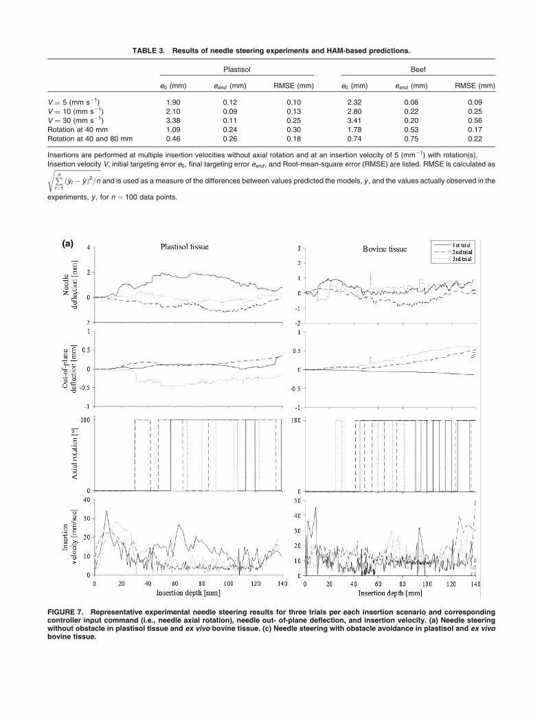
FIGURE 7. Representative experimental needle steering results for three trials per each insertion scenario and correspondingcontroller input command (i.e., needle axial rotation), needle out- of-plane deflection, and insertion velocity. (a) Needle steeringwithout obstacle in plastisol tissue and ex vivo bovine tissue. (c) Needle steering with obstacle avoidance in plastisol and ex vivobovine tissue.
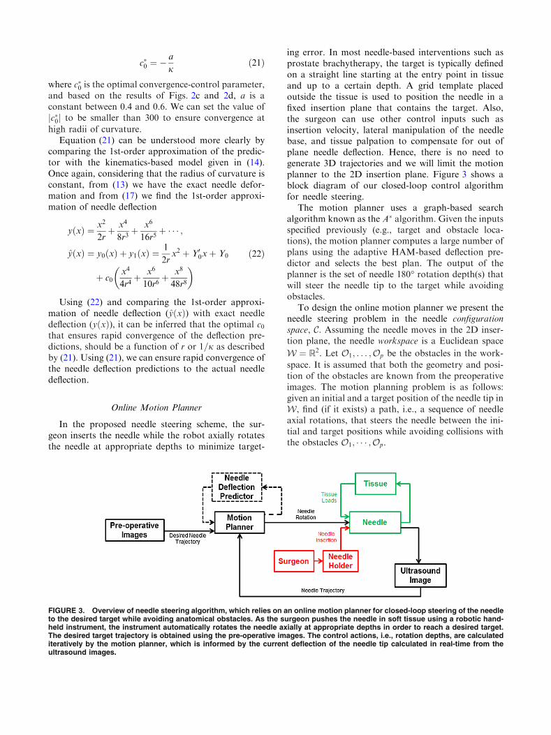
TABLE 3. Results of needle steering experiments and HAM-based predictions.
Plastisol Beef
e0 (mm) eend (mm) RMSE (mm) e0 (mm) eend (mm) RMSE (mm)
V = 5 (mm s21) 1.90 0.12 0.10 2.32 0.08 0.09
V = 10 (mm s21) 2.10 0.09 0.13 2.80 0.22 0.25
V = 30 (mm s21) 3.38 0.11 0.25 3.41 0.20 0.56
Rotation at 40 mm 1.09 0.24 0.30 1.78 0.53 0.17
Rotation at 40 and 80 mm 0.46 0.26 0.18 0.74 0.75 0.22
Insertions are performed at multiple insertion velocities without axial rotation and at an insertion velocity of 5 (mm21) with rotation(s).
Insertion velocity V, initial targeting error e0, final targeting error eend , and Root-mean-square error (RMSE) are listed. RMSE is calculated asffiffiffiffiffiffiffiffiffiffiffiffiffiffiffiffiffiffiffiffiffiffiffiffiffiffiffiffiffiffiffiPn
t¼1
ðyt � yÞ2=ns
and is used as a measure of the differences between values predicted the models, y , and the values actually observed in the
experiments, y , for n ¼ 100 data points.
Semi-Automated Needle Steering in Biological Tissue

steered inside soft-tissue. Some of the features of theproposed method are: (1) the model uses a depth-vary-ing radius of curvature and is able to predict changes inthe needle curvature due to the variations in the insertionvelocity or tissue inhomogeneity. (2) As the straight
needle deflects, its radius of curvature varies from1 to afinite value. The HAM based method is independent ofmagnitude of radius of curvature and other parametersof the model and predicts needle deflection with goodaccuracy. (3) The only parameters of the predictor arethe average radius of curvature of the needle and theinitial angle of the needle with respect to the insertionaxis. The experimental results showed, the predictorperformance is robust against uncertainty in the initialvalue of these parameters.
The predictor is implemented in a novel motionplanner that steers the needle inside the tissue toward apredefined target. In contrast to existing systems, ourapproach relies on a semi-automated needle steeringscheme. In our needle steering system the robot onlycontrols the needle axial rotation while the surgeon in-serts the needle. The experimental results demonstratethat our needle deflection predictor can accurately
FIGURE 7. continued.
TABLE 4. Results of needle steering experiments for10 trials.
Plastisol Beef
1st Scenario 2nd Scenario 1st Scenario 2nd Scenario
rot 9 5 11 4
emax 0.87 1.05 1.08 1.22
emean 0.51 0.74 0.71 0.87
eout 0.41 0.55 0.68 0.81
Maximum number of axial rotations rot, mean targeting error emean ,
maximum targeting error emax , and mean of out of plane deflection
eout .
KHADEM et al.

estimate tip position in real-time and themotion plannercan steer the needle toward the target position with amaximum in-plane error of 1.22 mm and maximum outof plane error of 0.87. Many factors such as needle tor-sional dynamics18 and tissue inhomogeneity can causeneedle out-of-plane deflection. In our human-in-the-loop approach, the robot only controls needle axialrotation. Thus, the surgeon can use other control inputssuch as insertion velocity,8 lateral manipulation of theneedle base,26 and tissue palpation3 to compensate forout of plane needle deflection.
The maximum targeting error of the proposedapproach is 1.08 mm for needle insertion on a straightline. In a recent study from our group, seed placementaccuracy in prostate brachytherapy is measured usingpost-implant ultrasound images.6 1619 seeds using 357strands were implanted in 15 patients’ prostate glands.Of the 1619 seeds implanted, 1196 (73.87%) wereconfidently identified in post-implant images. Theoverall mean in-plane and out-of-plane displacementswere 13 and 15 mm, respectively, which is higher thanour proposed method. However, this error includes theimage processing error, error in registering imagesbefore and after the surgery, and errors due to prostatemotion and deformation.
To furthermore elaborate the effectiveness of semi-automated needle steering and for benchmarking ourcontrolled needle insertion strategy, we have per-formed several fully automated and manual needleinsertions and compared the results with semi-auto-mated needle insertion. Three scenarios are used in theexperiments and 10 trials were performed for eachexperimental scenario:
(1) Fully automated needle insertion—Needle inser-tion and rotation is controlled by a robot to reacha desired target inside the tissue. The needle isrobotically inserted at velocities of 5, 20, and50 mm/sec, which is in the range of clinical needleinsertion velocities.17
(2) Semi-automated approach—The surgeon is incharge of needle insertion to ensure the safety ofthe procedure, while the robot is in charge ofcontrolling the needle trajectory via axial rotationsof the needle. Insertions are performed using thedevice shown in Fig. 5.
(3) Manual insertions—In manual needle insertions,the surgeon inserts the needle using the hand-helddevice shown in Fig. 5 and he can rotate theneedle 180 degrees axially by pressing a knoblocated in the control console. Real time visualimage feedback of needle tip were provided to thesurgeon during the insertions. Manual insertionsare performed by a skilled brachytherapist.
In all scenarios, the needle is steered to follow astraight line and reach a target at the depth of 140 mm(similar to clinical needle insertions in brachytherapy).Results are shown in Fig. 8.
Based on Fig. 8, human-in-the-loop strategy ismore accurate than manual. Figure 8c shows that
FIGURE 8. (a) A comparison between semi-automated nee-dle steering and manual needle insertion. Averaged data for10 trials are reported and the red bars denote the standarddeviation. (b) A comparison between fully automated needlesteering at different insertion velocities. Averaged data for 10trials are reported and the red bars denote the standarddeviation. (c) Accuracy results for different needle insertionscenarios. For each group, red line indicates median error,blue box indicates 25th and 75th percentile, and whiskersindicate minimum and maximum error.
Semi-Automated Needle Steering in Biological Tissue
the standard deviation of the error of the proposedapproach is smaller than manual needle insertion.This means our approach gives the same perfor-mance at different trials. Also, the semi-automatedapproach is more precise than fully automatedneedle steering. Results demonstrated that the nee-dle tracking error increases as the insertion velocityincreases. The reason is that the motion planner hasless time to compensate for tracking errors at highervelocities. Also mean out-of-plane needle deflectionfor fully automated needle insertion is 3.2 mm,which is 260% more than the semi-automated out-of-plane error. Based on the results, the proposedapproach shows more precision and repeatabilitycompared to conventional needle insertion strate-gies.
ACKNOWLEDGMENTS
This work was supported by the Natural Sciencesand Engineering Research Council (NSERC) of Ca-nada under grant CHRP 446520, the Canadian Insti-tutes of Health Research (CIHR) under grant CPG127768 and the Alberta Innovates - Health Solutions(AIHS) under grant CRIO 201201232. The authorswould like to thank Dr. Muhammad Faisal Jamalud-din who worked closely with us in conducting theevaluation experiments and helping to analyze ourresearch.
REFERENCES
1Adebar, T. K., A. E. Fletcher, and A. M. Okamura. 3-Dultrasound-guided robotic needle steering in biologicaltissue. IEEE Tran. Biomed. Eng. 61:2899–2910, 2014.2Choi, A. P. C., and Y. P. Zheng. Estimation of Young’smodulus and Poisson’s ratio of soft tissue from indentationusing two different-sized indentors: Finite element analysisof the finite deformation effect. Med. Biol. Eng. Comput.43:258–264, 2005.3Cowan, N. J., K. Goldberg, G. S. Chirikjian, G. Fichtin-ger, R. Alterovitz, K. B. Reed, V. Kallem, W. Park, S.Misra, and A. M. Okamura. Surgical Robotics: SystemsApplications and Visions. US: Springer, pp. 557–582, 2011.4Delling, D., P. Sanders, D. Schultes, and D. Wagner.Algorithmics of Large and Complex Networks: Design,Analysis, and Simulation. Berlin: Springer, pp. 117–139,2009.5Goksel, O., E. Dehghan, and S. E. Salcudean. Modelingand simulation of flexible needles. Med. Eng. Phys.31:1069–1078, 2009.6Jamaluddin, M. F., S. Ghosh, M. Waine, et al. Quantifyingiodine-125 placement accuracy in prostate brachytherapyusing post-implant transrectal ultrasound images.Brachytherapy 15:S180, 2016.
7Khadem, M., C. Rossa, R. S. Sloboda, N. Usmani, and M.Tavakoli. Ultrasound-guided model predictive control ofneedle steering in biological tissue. J. Med. Robot. Res01:1640007–1640007, 2016.8Khadem, M., C. Rossa, N. Usmani, R. S. Sloboda, and M.Tavakoli. A two-body rigid/flexible model of needlesteering dynamics in soft tissue. IEEE/ASME TransMechatron. 21:2352–2364, 2016.9Liao, S. Homotopy analysis method: a new analyticmethod for nonlinear problems. Appl. Math. Mech.19:957–962, 1998.
10Liao, S. Homotopy Analysis Method in Nonlinear Differ-ential Equations. Berlin: Springer, 2012.
11Maghsoudi, A., and M. Jahed. Needle dynamics modellingand control in prostate brachytherapy. IET Control TheoryAppl. 6:1671–1681, 2012.
12Minhas D. S., J. A. Engh, M. M. Fenske, and C. N. Riv-iere. Modeling of needle steering via duty-cycled spinning.In: 29th Annual International Conference of the IEEEEngineering in Medicine and Biology Society (EMBS), pp.2756–2759.
13Misra S., K. B. Reed, A. S. Douglas, K. T. Ramesh, and A.M. Okamura. Needle-tissue interaction forces for bevel-tipsteerable needles. In: 2nd IEEE RAS & EMBS Interna-tional Conference on Biomedical Robotics and Biomecha-tronics, BioRob, 2008, pp. 224–231.
14Misra, S., K. B. Reed, B. W. Schafer, K. T. Ramesh, andA. M. Okamura. Mechanics of flexible needles roboticallysteered through soft tissue. Int. J. Robot. Res. 29:1640–1660, 2010.
15Moreira, P., and S. Misra. Biomechanics-based curvatureestimation for ultrasound-guided flexible needle steering inbiological tissues. Ann. Biomed. Eng. 43:1716–1726, 2015.
16Patil, S., J. Burgner, R. J. Webster, and R. Alterovitz.Needle steering in 3D via rapid replanning. IEEE Trans.Robot. 30:853–864, 2014.
17Podder T. K., D. P. Clark, D. Fuller, J. Sherman and et.al.Effects of velocity modulation during surgical needleinsertion. In: 27th Annual International Conference of theEngineering in Medicine and Biology Society, IEEE-EMBS. pp. 5766–5770.
18Reed K. B., V. Kallem, R. Alterovitz, K. Goldberg, A. M.Okamura, and N. J. Cowan. Integrated planning andimage-guided control for planar needle steering. In: 2ndIEEE RAS & EMBS International Conference onBiomedical Robotics and Biomechatronics, BioRob, pp.819–824.
19Roesthuis R. J., M. Abayazid and S. Misra. Mechanics-based model for predicting in-plane needle deflection withmultiple bends. In: 4th IEEE RAS EMBS InternationalConference on Biomedical Robotics and Biomechatronics,pp. 69–74.
20Rossa C., N. Usmani, R. Sloboda and M. Tavakoli. Ahand-held assistant for semi-automated percutaneous nee-dle steering. IEEE Trans. Biomed. Eng. pp. 1–1, 2016.
21Rucker, D. C., J. Das, H. B. Gilbert, P. J. Swaney, M. I.Miga, N. Sarkar, and R. J. Webster. Sliding mode controlof steerable needles. IEEE Trans. Robot. 29:1289–1299,2013.
22Swensen, J. P., M. Lin, A. M. Okamura, and N. J. Cowan.Torsional dynamics of steerable needles: modeling andfluoroscopic guidance. IEEE Trans. Biomed. Eng. 61:2707–2717, 2014.
23Vrooijink G. J., M. Abayazid, S. Patil, R. Alterovitz, and S.Misra. Needle path planning and steering in a three-
KHADEM et al.