SECTION A Torque and Statics - ap.physicsatthebay.com Practice FR.pdf · SECTION A Torque and...
4
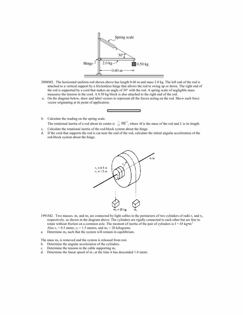
2008M2. The horizontal uniform rod shown above has length 0.60 m and mass 2.0 kg. The left end of the rod is attached to a vertical support by a frictionless hinge that allows the rod to swing up or down. The right end of the rod is supported by a cord that makes an angle of 30° with the rod. A spring scale of negligible mass measures the tension in the cord. A 0.50 kg block is also attached to the right end of the rod. a. On the diagram below, draw and label vectors to represent all the forces acting on the rod. Show each force vector originating at its point of application. b. Calculate the reading on the spring scale. The rotational inertia of a rod about its center is 1 12 ML 2 , where M is the mass of the rod and L is its length. c. Calculate the rotational inertia of the rod-block system about the hinge. d. If the cord that supports the rod is cut near the end of the rod, calculate the initial angular acceleration of the rod-block system about the hinge. 1991M2. Two masses. m 1 and m 2 are connected by light cables to the perimeters of two cylinders of radii r 1 and r 2 , respectively. as shown in the diagram above. The cylinders are rigidly connected to each other but are free to rotate without friction on a common axle. The moment of inertia of the pair of cylinders is I = 45 kg•m 2 Also r 1 = 0.5 meter, r 2 = 1.5 meters, and m 1 = 20 kilograms. a. Determine m 2 such that the system will remain in equilibrium. The mass m 2 is removed and the system is released from rest. b. Determine the angular acceleration of the cylinders. c. Determine the tension in the cable supporting m 1 d. Determine the linear speed of m 1 at the time it has descended 1.0 meter.
Transcript of SECTION A Torque and Statics - ap.physicsatthebay.com Practice FR.pdf · SECTION A Torque and...
!!
!! 227
233
!
238
!!
!!
240
241
!!!
245