SECTION 54B SMART WIRING SYSTEM (SWS) - LIL EVO 8 Service Manual/xEvo8/Evo8/Workshop/54B... · It...
121
54B-1 General ........................................................2 Special Tools ..............................................2 Troubleshooting .........................................4 1. Before starting troubleshooting .........................4 2. Standard flow of diagnostic troubleshooting .....4 3. SWS monitor connections.................................5 4. ECU check service points .................................8 5. Service data check service points ....................9 6. Pulse check service points (MUT-II/III or voltmeter) ........................................................20 7. MUT-II/III flight recorder functions...................20 8. Chart of trouble symptoms..............................21 9. Confirming problems in input signal check .....24 10. Inspection procedures classified by diagnosis code ...............................................................26 11. Chart of terminal voltages ...........................112 On-vehicle servicing .............................117 Adjustment function (User mode) ......................117 Adjustment function (Dealer mode) ...................118 SECTION 54B SMART WIRING SYSTEM (SWS) CONTENTS
Transcript of SECTION 54B SMART WIRING SYSTEM (SWS) - LIL EVO 8 Service Manual/xEvo8/Evo8/Workshop/54B... · It...

54B-1
General........................................................2Special Tools ..............................................2Troubleshooting.........................................4
1. Before starting troubleshooting .........................42. Standard flow of diagnostic troubleshooting .....43. SWS monitor connections.................................54. ECU check service points.................................85. Service data check service points ....................96. Pulse check service points (MUT-II/III or
voltmeter) ........................................................207. MUT-II/III flight recorder functions...................208. Chart of trouble symptoms..............................219. Confirming problems in input signal check .....2410. Inspection procedures classified by diagnosis
code ...............................................................2611. Chart of terminal voltages ...........................112
On-vehicle servicing .............................117Adjustment function (User mode)......................117Adjustment function (Dealer mode)...................118
SECTION 54B
SMART WIRING SYSTEM(SWS)
CONTENTS
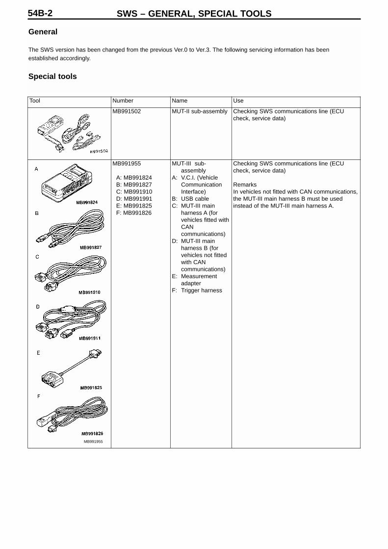
Tool Number Name Use
MB991502 MUT-II sub-assembly Checking SWS communications line (ECUcheck, service data)
MB991955
A: MB991824B: MB991827C: MB991910D: MB991991E: MB991825F: MB991826
MUT-III sub-assembly
A: V.C.I. (VehicleCommunicationInterface)
B: USB cableC: MUT-III main
harness A (forvehicles fitted withCANcommunications)
D: MUT-III mainharness B (forvehicles not fittedwith CANcommunications)
E: Measurementadapter
F: Trigger harness
Checking SWS communications line (ECUcheck, service data)
RemarksIn vehicles not fitted with CAN communications,the MUT-III main harness B must be usedinstead of the MUT-III main harness A.
SWS – GENERAL, SPECIAL TOOLS54B-2
General
The SWS version has been changed from the previous Ver.0 to Ver.3. The following servicing information has beenestablished accordingly.
Special tools
MB991955
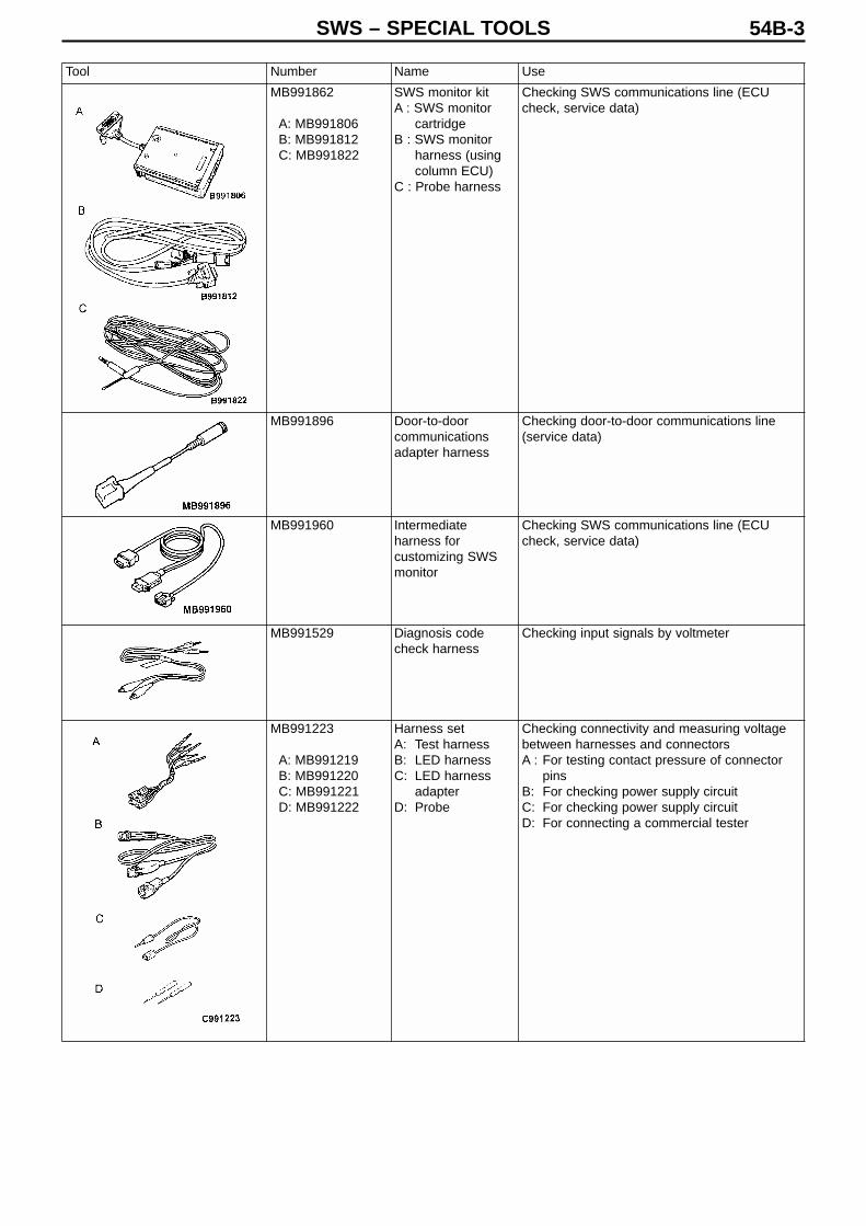
Tool Number Name Use
MB991862
A: MB991806B: MB991812C: MB991822
SWS monitor kitA : SWS monitor
cartridgeB : SWS monitor
harness (usingcolumn ECU)
C : Probe harness
Checking SWS communications line (ECUcheck, service data)
MB991896 Door-to-doorcommunicationsadapter harness
Checking door-to-door communications line(service data)
MB991960 Intermediateharness forcustomizing SWSmonitor
Checking SWS communications line (ECUcheck, service data)
MB991529 Diagnosis codecheck harness
Checking input signals by voltmeter
MB991223
A: MB991219B: MB991220C: MB991221D: MB991222
Harness setA: Test harnessB: LED harnessC: LED harness
adapterD: Probe
Checking connectivity and measuring voltagebetween harnesses and connectorsA : For testing contact pressure of connector
pinsB: For checking power supply circuitC: For checking power supply circuitD: For connecting a commercial tester
SWS – SPECIAL TOOLS 54B-3
SWS – TROUBLESHOOTING54B-4
Troubleshooting
1. Before starting troubleshooting
Before starting troubleshooting, make sure that there is no problem with either of the following: • Check the state of coupling of the connectors between the ETACS-ECU and the junction box, and between the front ECUand the relay box in the engine room• Check that the fuses and fusible links relating to all systems have not blown.
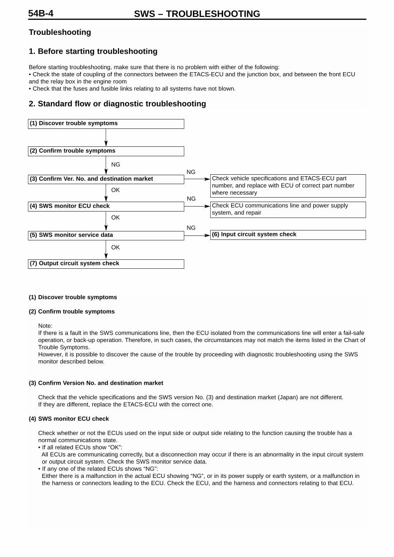
2. Standard flow or diagnostic troubleshooting
(1) Discover trouble symptoms
(2) Confirm trouble symptoms
(3) Confirm Ver. No. and destination market
(4) SWS monitor ECU check
(5) SWS monitor service data
(7) Output circuit system check
Check ECU communications line and power supplysystem, and repair
(6) Input circuit system check
Check vehicle specifications and ETACS-ECU partnumber, and replace with ECU of correct part numberwhere necessary
(1) Discover trouble symptoms
(2) Confirm trouble symptoms
Note:If there is a fault in the SWS communications line, then the ECU isolated from the communications line will enter a fail-safeoperation, or back-up operation. Therefore, in such cases, the circumstances may not match the items listed in the Chart ofTrouble Symptoms.However, it is possible to discover the cause of the trouble by proceeding with diagnostic troubleshooting using the SWSmonitor described below.
(3) Confirm Version No. and destination market
Check that the vehicle specifications and the SWS version No. (3) and destination market (Japan) are not different.If they are different, replace the ETACS-ECU with the correct one.
(4) SWS monitor ECU check
Check whether or not the ECUs used on the input side or output side relating to the function causing the trouble has anormal communications state.• If all related ECUs show “OK”:
All ECUs are communicating correctly, but a disconnection may occur if there is an abnormality in the input circuit system or output circuit system. Check the SWS monitor service data.
• If any one of the related ECUs shows “NG”:Either there is a malfunction in the actual ECU showing “NG”, or in its power supply or earth system, or a malfunction in the harness or connectors leading to the ECU. Check the ECU, and the harness and connectors relating to that ECU.
NGNG
NG
NG
OK
OK
OK

(5) SWS monitor service data
From the Diagnosis by Function menu, select the function which is causing the trouble, and check the service data shownfor each item of the function.
Note:The SWS monitor service data also includes a Service data menu, in addition to the Diagnosis by Function menu. All items for all ECUs can be checked.(1) Monitoring the SWS communications lineIt can be determined whether the cause is located in the input circuit system or the output circuit system, by checkingwhether or not the communications data is normal.
• If the switch status does not match the service data display:Input system relating to function where trouble is occurring.
• If the switch status matches the service data display:Output system relating to function where trouble is occurring.
(2) Monitoring the door-to-door communications lineThe communications data transmitted by the electric window module (electric window main switch) can be checked. Bychanging the position at which the probe is inserted, the location of the cause can be narrowed down.
• If the switch status does not match the service data display:Harness/connector between the electric window module and the location of the probe.
• If the switch status matches the service data display:Harness/connector from the location of the probe to the respective door motors, or the motors themselves.
(6) Input circuit system checkCheck the relevant switches, sensors and input side ECUs, and the harnesses and connectors between them.
(7) Output circuit system checkCheck the output side ECUs and load sections and the harnesses and connectors between them.
SWS – TROUBLESHOOTING 54B-5
3. SWS monitor connections
How to connect the SWS communications line
Note :Connection or disconnection of the SWS monitor and MUT-II/IIImust always be carried out with the ignition switch in theLOCK (OFF) position.
(Connecting the SWS monitor harness to the column switch)(1) Connect the MUT-II/III to the diagnosis connector.(2) Remove the column cover.(3) Detach the column switch connector.(4) Connect the special SWS monitor harness (MB991812) to the
column switch connector and the column switch harness sideconnector.
Column switchconnector
Column switch harnessside connector

SWS – TROUBLESHOOTING54B-6
(Connecting to the diagnosis connector using theIntermediate harness for customizing the SWS monitor(using the MUT-II))
(1) Connect the MUT-II to the Intermediate harness for customizing theSWS monitor (MB991960).
(2) Take the Intermediate harness for customizing the SWS monitor(connected at step (1)), and connect it to the diagnosis connector andthe SWS monitor.
(Connecting to the diagnosis connector using theIntermediate harness for customizing the SWS monitor(using the MUT-III))
(1) Connect the MUT-III main harness B (MB991911) to the Intermediateharness for customizing the SWS monitor (MB991960).
(2) Take the MUT-III main harness B (connected at step (1)), and connectit to the V.C.I. (MB991824).
(3) Take the Intermediate harness for customizing the SWS monitor(MB991960) (connected at step 1), and connect it to the diagnosisconnector and the SWS monitor.
Door-to-door communications connection method
(1) Connect the SWS monitor harness (MB991812) and the Door-to-doorcommunications adapter harness (MB991896).
(2) Connect the Probe harness (MB991822) to the Door-to-doorcommunications adapter harness (MB991896) connected at step (1).
(3) After all connections have been made, insert the probe section of theprobe harness into the terminals of the respective female connectorson the door-to-door communications line, from the rear side of theconnector.
Diagnosis connector
SWS monitor
Diagnosis connector
SWS monitor
SWS – TROUBLESHOOTING 54B-7
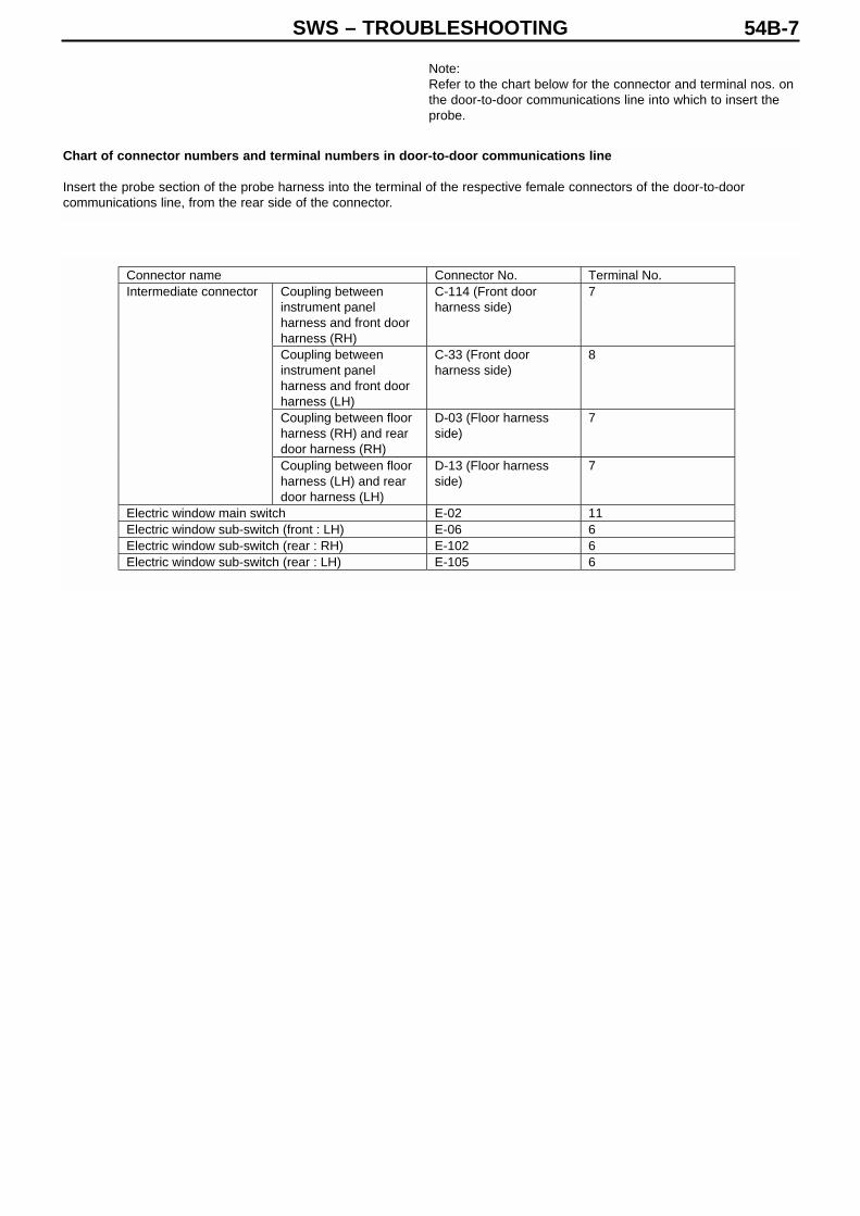
Note:Refer to the chart below for the connector and terminal nos. onthe door-to-door communications line into which to insert theprobe.
Chart of connector numbers and terminal numbers in door-to-door communications line
Insert the probe section of the probe harness into the terminal of the respective female connectors of the door-to-doorcommunications line, from the rear side of the connector.
Connector name Connector No. Terminal No.Coupling betweeninstrument panelharness and front doorharness (RH)
C-114 (Front doorharness side)
7
Coupling betweeninstrument panelharness and front doorharness (LH)
C-33 (Front doorharness side)
8
Coupling between floorharness (RH) and reardoor harness (RH)
D-03 (Floor harnessside)
7
Intermediate connector
Coupling between floorharness (LH) and reardoor harness (LH)
D-13 (Floor harnessside)
7
Electric window main switch E-02 11Electric window sub-switch (front : LH) E-06 6Electric window sub-switch (rear : RH) E-102 6Electric window sub-switch (rear : LH) E-105 6

SWS – TROUBLESHOOTING54B-8
4. ECU check service points
(1) The ECU check is performed using the MUT-II/III and SWS monitor.(See MUT-II Reference Manual or MUT-III Instruction Manual)
(2) The following ECU checks can be performed when the ECU is connected to the MUT-II/III and the SWS monitor.
Note: If an abnormality arises during ECU checking, then troubleshooting should be performed by referring to the Inspectionprocedures classified by trouble symptoms.(See p.54B-21)
ECU subjected to ECU communications check using SWS monitor, and possible ECU states
Note:(1) *1: If the ignition switch is OFF when “NG” is displayed on the ETACS-ECU, then “NG” is displayed on the column ECU.(2) *2: If “NG” is displayed on the ETACS-ECU, then “NG” will be displayed on the front ECU, electric window main switch(electric window module), and sunroof assembly (sunroof ECU).(3) *3: If “NG” is displayed on the column ECU, then “NG” will be displayed on the multi-centre display.
ECU underinspection
MUT display Normal state ECU state
Column switch(column ECU)
Column ECU OK*1 Column switch, power supply,earth, communications line : allnormal
ETACS-ECU ETACS OK ETACS-ECU, power supply, earth,communications line : all normal
Front ECU Front ECU OK*2 Front ECU, power supply, earth,communications line : all normal
Electric window mainswitch (electricwindow module)
P/W module OK*2
(Ignition switch:ON)
Electric window main switch, powersupply, earth, communications line: all normal
Sunroof motorassembly (sunroofECU)
Sunroof ECU OK*2 Sunroof motor assembly, powersupply, earth, communications line: all normal
Multi-centre display Centre display OK*3 Multi-centre display, power supply,earth, communications line : allnormal
ECUs relating toparts of SWS otherthan the above
All other ECU apartfrom above
NG ECU not installed

SWS – TROUBLESHOOTING 54B-9
5. Service data check service points
(1) The service data is checked using the MUT-II/III and the SWS monitor.A service data check performed using the SWS monitor only relates to the signals present on the SWS communicationsline and the door-to-door communications line. For information on the input signals which are not checked by the SWSmonitor, refer to the Pulse check service points (MUT-II/III or voltmeter) p.54B-20.
(2) The following input signals can be checked when the MUT-II/III and SWS monitor are connected.
Note: If an abnormality arises during service data checking, then troubleshooting should be performed by referring to Confirmingproblems in input signal check (Service data, Diagnosis by Function, or pulse check). (See p.54B-24)
(Service data chart)
• Column switch (column ECU)
Item No. Check item MUT display Check conditions Normalstate
Lighting switch : HEAD ON00 Headlight switch Headlight SWLighting switch : not HEAD OFFLight switch : TAIL ON01 Tail light switch Tail light SWLight switch : OFF OFFDimmer switch : ON ON02 Dimmer switch Dimmer SWDimmer switch : OFF OFFPassing switch : ON ON03 Passing switch Passing SWPassing switch : OFF OFFWiper switch : INT ON05 Windscreen
intermittent wiperswitch
INT wiper SWWiper switch : not INT OFF
Wiper switch : LO ON06 Windscreen low-speed wiper switch
LO wiper SWWiper switch : not LO OFFWiper switch : HI ON07 Windscreen high-
speed wiper switchHI wiper SW
Wiper switch : not HI OFFPower switch : Mist ON08 Windscreen mist
wiper switchMist wiper SW
Power switch : not Mist OFFWindscreen washer switch : ON ON09 Windscreen washer
switchFront washerSW Windscreen washer switch : OFF OFF
Turn indicator light switch : RH ON10 RH turn indicator lightswitch
RH turn indicatorlight SW Turn indicator light switch : not RH OFF
Turn indicator light switch : LH ON11 LH turn indicator lightswitch
LH turn indicatorlight SW Turn indicator light switch : not LH OFF
Rear wiper switch : INT ON13 Rear wiper switch Rear wiper SWRear wiper switch : not INT OFFRear wiper switch : Washer ON14 Rear washer switch Rear washer SWRear wiper switch not Washer OFF
SWS – TROUBLESHOOTING54B-10
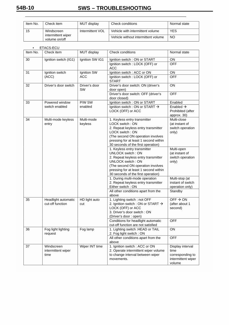
Item No. Check item MUT display Check conditions Normal state
Vehicle with intermittent volume YES15 Windscreenintermittent wipervolume on/off
Intermittent VOL
Vehicle without intermittent volume NO
• ETACS-ECUItem No. Check item MUT display Check conditions Normal state
Ignition switch : ON or START ON30 Ignition switch (IG1) Ignition SW IG1Ignition switch : LOCK (OFF) orACC
OFF
Ignition switch : ACC or ON ON31 Ignition switch(ACC)
Ignition SWACC Ignition switch : LOCK (OFF) or
STARTOFF
Driver’s door switch: ON (driver’sdoor open)
ON32 Driver’s door switch Driver’s doorSW
Driver’s door switch: OFF (driver’sdoor closed)
OFF
Ignition switch : ON or START Enabled33 Powered windowswitch enabled
P/W SWenabled Ignition switch : ON or START
LOCK (OFF) or ACCEnabled Prohibited (afterapprox. 30)
1. Keyless entry transmitterLOCK switch : ON2. Repeat keyless entry transmitterLOCK switch : ON(The second ON operation involvespressing for at least 1 second within30 seconds of the first operation)
Multi-close(at instant ofswitch operationonly)
1. Keyless entry transmitterUNLOCK switch : ON2. Repeat keyless entry transmitterUNLOCK switch : ON(The second ON operation involvespressing for at least 1 second within30 seconds of the first operation)
Multi-open(at instant ofswitch operationonly)
1. During multi-mode operation2. Repeat keyless entry transmitterEither switch : ON
Multi-stop (atinstant of switchoperation only)
34 Multi-mode keylessentry
Multi-modekeyless
All other conditions apart from theabove
Standby
1. Lighting switch : not OFF2. Ignition switch : ON or START LOCK (OFF) or ACC3. Driver’s door switch : ON(Driver’s door : open)
OFF ON(after about 1second)
35 Headlight automaticcut-off function
HD light autocut
Conditions for headlight automaticcut-off function are not satisfied
OFF
1. Lighting switch :HEAD or TAIL2. Fog light switch : ON
ON36 Fog light lightingrequest
Fog lamp
All other conditions apart from theabove
OFF
37 Windscreenintermittent wipertime
Wiper INT time 1. Ignition switch : ACC or ON2. Operate intermittent wiper volumeto change interval between wipermovements.
Display intervaltimecorresponding tointermittent wipervolume

SWS – TROUBLESHOOTING 54B-11
Item No. Check item MUT display Check conditions Normal state
Any door : open ON38 All door switch Security alarmAll doors : closed OFFReversing light switch : ON ON41 Reversing light
switchInhibitor SW(R) Reversing light switch : OFF OFF
1. Wiper switch : INT2. Travel at 7 km/h or above
YES42 Wiper driveindication at start up
Wiper driveindication
Any conditions apart from the above NO1. Ignition switch : LOCK (OFF)2. Key reminder switch : ON3. Driver’s door switch : ON(Driver-s door : open)
ON43 Buzzer Buzzer
Conditions for sounding of anybuzzer are not satisfied.
OFF
Note : When inspecting Item No.43 Buzzer, in addition to the conditions listed in the table, “ON” isdisplayed due to operation of the light switch-off reminder warning function.
• Multi-display
Item No. Check item MUT display Check conditions Normal state
1. Ignition switch : ACC or ON2. Perform audio preset operation.
ON (2 kHz) (onlyat instant ofswitch operation)
60 beep data beep data
Any other conditions OFFIgnition switch : LOCK (OFF) Asleep61 Centre display
sleep modeDisplay asleep
Ignition switch : ACC or ON Active1. Ignition switch : ACC or ON2. Perform audio preset operation.
YES (Only atinstant of switchoperation)
62 Centre display inputsignal
Display input
Any other conditions NO

SWS – TROUBLESHOOTING54B-12
Item No. Check item MUT display Check conditions Normal state
Lighting switch : not OFF(except for high-beam on)or Wiper switch : not OFF
Normal response
• Ignition switch : ON or START• Lighting switch : OFF• Wiper switch : OFF
Sleep response
• Lighting switch : HEAD• Headlight : High beam on
High beamresponse
70 Front ECUresponse
Front ECUresponse
No response
Note:When Item No.70 Front ECU check is performed and “No response” is displayed, then “NG” is shown inthe ECU check as well.
• Electric window main switch (electric window module)
Item No. Check item MUT display Check conditions Normal state
Ignition switch : ON or START Normal response1. Ignition switch : ON or START2. Operate any switch of the electricwindow main switch
Input check (onlyat instant ofswitch operation)
71 Electric windowmodule response
P/W moduleresponse
No response
Note: When Item No.71 P/W module response check is performed and “No response” is displayed, then“NG” is shown in the ECU check as well.
• Sunroof motor assembly (sunroof ECU)
Item No. Check item MUT display Check conditions Normal state
1. Ignition switch : ON or START2. Sunroof halted
Normal response Sleepresponse (afterabout 30 secs.)
1. Ignition switch : ON or START2. Sunroof switch : Any switch ON
Input check Normal response
72 Sunroof ECUresponse
Sunroof ECUresponse
No response
Note :Note: When Item No.72 Sunroof ECU response check is performed and “No response” is displayed,then “NG” is shown in the ECU check as well.
SWS – TROUBLESHOOTING 54B-13
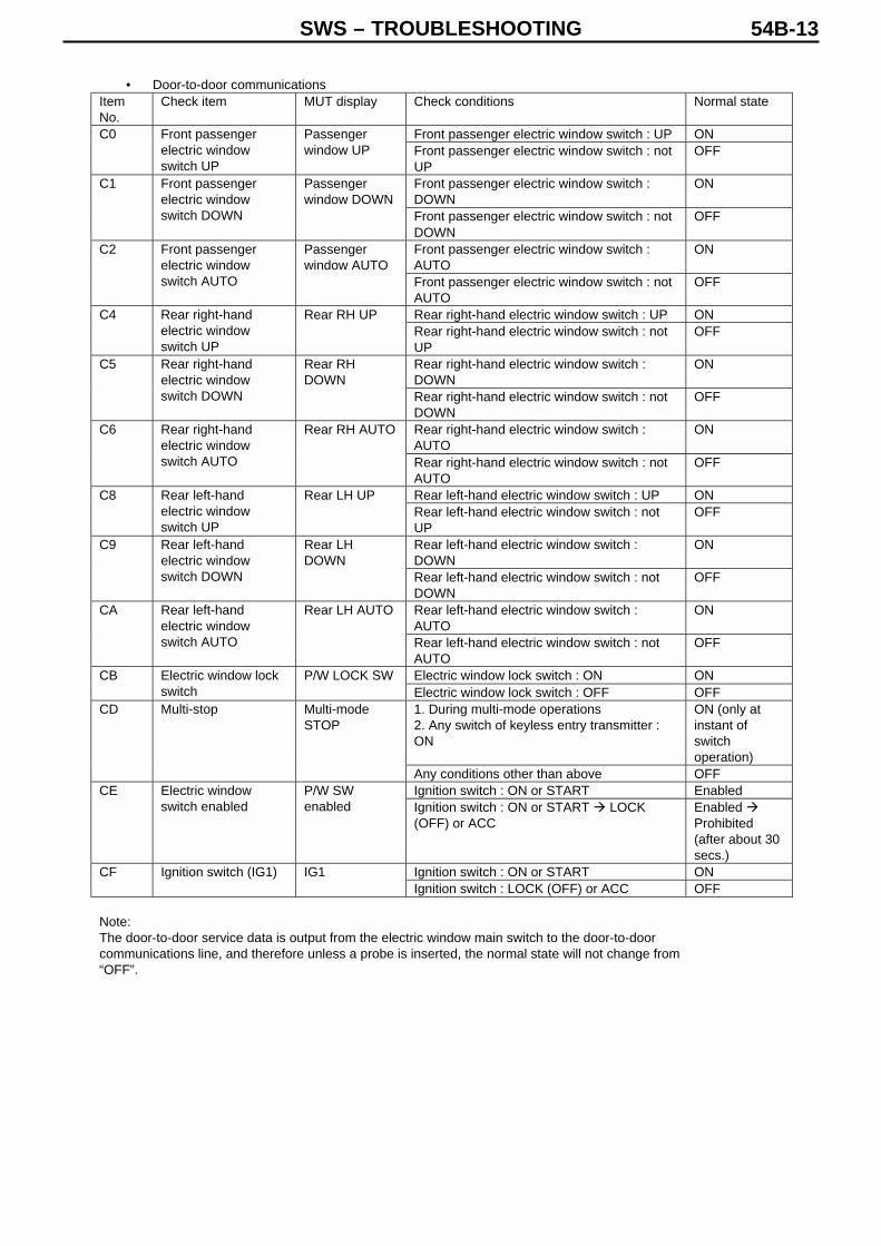
• Door-to-door communicationsItemNo.
Check item MUT display Check conditions Normal state
Front passenger electric window switch : UP ONC0 Front passengerelectric windowswitch UP
Passengerwindow UP Front passenger electric window switch : not
UPOFF
Front passenger electric window switch :DOWN
ONC1 Front passengerelectric windowswitch DOWN
Passengerwindow DOWN
Front passenger electric window switch : notDOWN
OFF
Front passenger electric window switch :AUTO
ONC2 Front passengerelectric windowswitch AUTO
Passengerwindow AUTO
Front passenger electric window switch : notAUTO
OFF
Rear right-hand electric window switch : UP ONC4 Rear right-handelectric windowswitch UP
Rear RH UPRear right-hand electric window switch : notUP
OFF
Rear right-hand electric window switch :DOWN
ONC5 Rear right-handelectric windowswitch DOWN
Rear RHDOWN
Rear right-hand electric window switch : notDOWN
OFF
Rear right-hand electric window switch :AUTO
ONC6 Rear right-handelectric windowswitch AUTO
Rear RH AUTO
Rear right-hand electric window switch : notAUTO
OFF
Rear left-hand electric window switch : UP ONC8 Rear left-handelectric windowswitch UP
Rear LH UPRear left-hand electric window switch : notUP
OFF
Rear left-hand electric window switch :DOWN
ONC9 Rear left-handelectric windowswitch DOWN
Rear LHDOWN
Rear left-hand electric window switch : notDOWN
OFF
Rear left-hand electric window switch :AUTO
ONCA Rear left-handelectric windowswitch AUTO
Rear LH AUTO
Rear left-hand electric window switch : notAUTO
OFF
Electric window lock switch : ON ONCB Electric window lockswitch
P/W LOCK SWElectric window lock switch : OFF OFF1. During multi-mode operations2. Any switch of keyless entry transmitter :ON
ON (only atinstant ofswitchoperation)
CD Multi-stop Multi-modeSTOP
Any conditions other than above OFFIgnition switch : ON or START EnabledCE Electric window
switch enabledP/W SWenabled Ignition switch : ON or START LOCK
(OFF) or ACCEnabled Prohibited(after about 30secs.)
Ignition switch : ON or START ONCF Ignition switch (IG1) IG1Ignition switch : LOCK (OFF) or ACC OFF
Note:The door-to-door service data is output from the electric window main switch to the door-to-doorcommunications line, and therefore unless a probe is inserted, the normal state will not change from“OFF”.
SWS – TROUBLESHOOTING54B-14
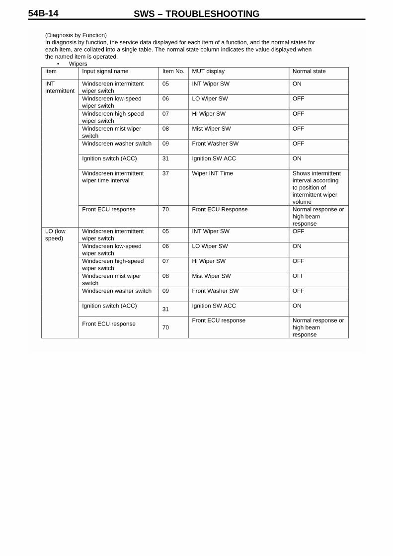
(Diagnosis by Function)In diagnosis by function, the service data displayed for each item of a function, and the normal states foreach item, are collated into a single table. The normal state column indicates the value displayed whenthe named item is operated.
• WipersItem Input signal name Item No. MUT display Normal state
Windscreen intermittentwiper switch
05 INT Wiper SW ON
Windscreen low-speedwiper switch
06 LO Wiper SW OFF
Windscreen high-speedwiper switch
07 Hi Wiper SW OFF
Windscreen mist wiperswitch
08 Mist Wiper SW OFF
Windscreen washer switch 09 Front Washer SW OFF
Ignition switch (ACC) 31 Ignition SW ACC ON
Windscreen intermittentwiper time interval
37 Wiper INT Time Shows intermittentinterval accordingto position ofintermittent wipervolume
INTIntermittent
Front ECU response 70 Front ECU Response Normal response orhigh beamresponse
Windscreen intermittentwiper switch
05 INT Wiper SW OFF
Windscreen low-speedwiper switch
06 LO Wiper SW ON
Windscreen high-speedwiper switch
07 Hi Wiper SW OFF
Windscreen mist wiperswitch
08 Mist Wiper SW OFF
Windscreen washer switch 09 Front Washer SW OFF
Ignition switch (ACC)31
Ignition SW ACC ON
LO (lowspeed)
Front ECU response70
Front ECU response Normal response orhigh beamresponse

SWS – TROUBLESHOOTING 54B-15
Item Input signal name Item No. MUT display Normal state
Windscreen intermittentwiper switch
05 INT Wiper SW OFF
Windscreen low-speedwiper switch
06 LO Wiper SW OFF
Windscreen high-speedwiper switch
07 Hi Wiper SW ON
Windscreen mist wiperswitch
08 Mist Wiper SW OFF
Windscreen washer switch 09 Front Washer SW OFF
Ignition switch (ACC) 31 Ignition SW ACC ON
HI(Highspeed)
Front ECU response 70 Front ECU Response Normal response orhigh beamresponse
Windscreen intermittentwiper switch
05 INT Wiper SW OFF
Windscreen low-speedwiper switch
06 LO Wiper SW ON
Windscreen high-speedwiper switch
07 Hi Wiper SW OFF
Windscreen mist wiperswitch
08 Mist Wiper SW OFF
Windscreen washer switch 09 Front Washer SW OFF
Ignition switch (ACC)31
Ignition SW ACC ON
Mist
Front ECU response70
Front ECU response Normal response orhigh beamresponse
Windscreen mist wiperswitch
08 Mist Wiper SW OFF
Windscreen washer switch 09 Front Washer SW ON
Ignition switch (ACC) 31 Ignition SW ACC ONWasher
Front ECU response70
Front ECU response Normal response orhigh beamresponse

SWS – TROUBLESHOOTING54B-16
• Rear WiperItem Input signal name Item No. MUT display Normal state
Rear wiper switch 13 Rear wiper SW ONRear washer switch 14 Rear washer SW OFFRear wiperIgnition switch (ACC) 31 Ignition SW ACC ONRear wiper switch 13 Rear wiper SW ONIgnition switch (ACC) 31 Ignition SW ACC ON
Reversetravel
Reversing light switch 41 Inhibitor SW (R) ONRear washer switch 14 Rear washer SW ONRear
washer Ignition switch (ACC) 31 Ignition SW ACC ON
• LightingItem Input signal name Item No. MUT display Normal state
Headlight switch 00 Headlight SW OFFTail light switch 01 Tail light SW OFFPassing switch 03 Passing SW OFFIgnition switch (IG1) 30 Ignition SW IG1 ONHeadlight automatic cut-offfunction
35HD light auto cut OFF
Lighting
Front ECU response 70Front ECU response Normal response or
sleep responseHeadlight switch 00 Headlight SW OFFTail light switch 01 Tail light SW ONPassing switch 03 Passing SW OFFIgnition switch (IG1) 30 Ignition SW IG1 ONHeadlight automatic cut-offfunction
35HD light auto cut OFF
Tail
Front ECU response 70 Front ECU response Normal responseHeadlight switch 00 Headlight SW ONDimmer switch 02 Dimmer SW OFFPassing switch 03 Passing SW OFFIgnition switch (IG1) 30 Ignition SW IG1 ONHeadlight automatic cut-offfunction
35HD light auto cut OFF
LO (lowbeam)
Front ECU response 70 Front ECU response Normal responseHeadlight switch 00 Headlight SW ONDimmer switch 02 Dimmer SW ONIgnition switch (IG1) 30 Ignition SW IG1 ONHeadlight automatic cut-offfunction
35HD light auto cut OFF
HI (highbeam)
Front ECU response 70Front ECU response High beam
responsePassing switch 03 Passing SW ONPassingFront ECU response 70 Front ECU response Normal response or
high beamresponse

SWS – TROUBLESHOOTING 54B-17
• Item Input signal name Item No. MUT display Normal state
Headlight switch 00 Headlight SWTail light switch 01 Tail light SW
Any ON
Ignition switch (IG1) 30 Ignition SW IG1 ONHeadlight automatic cut-offfunction
35HD light auto cut OFF
Fog light light request 36 Fog lamp ON
Fog lamp
Front ECU response 70 Front ECU response Normal responseHeadlight switch 00 Headlight SWTail light switch 01 Tail light SW
Any ON
Ignition switch (IG1) 30 Ignition SW IG1 OFFDriver’s door switch 32 Driver’s door SW ONHeadlight automatic cut-offfunction
35HD light auto cut ON
Automaticcut-off
Front ECU response 70Front ECU response Normal response or
high beamresponse
Note : When performing an input signal check for the lighting, tail lights, LO (low beam) or HI (highbeam) operation, the headlight cut-off function is set to be switched OFF in order that accurateconclusions can be made when the ignition switch is “ON”. However, since this has no direct bearing onthe actual operation of the lights, it is not included in the reverse conditions in the title section of theMUT-II display.When performing a HI (high beam) check, the display for Item No.02 Dimmer SW is “OFF”, even whenthe high beam is lit. Therefore, check that the display changes to “ON” when the dimmer switch isoperated.
• Turn indicator lampsItem Input signal name Item No. MUT display Normal state
RH Turn indicator lightswitch
10 RH turn indicator SW ON
LH Turn indicator lightswitch
11 LH turn indicator SW OFF
RH Turnindicatorlight
Ignition switch (IG1) 30 Ignition SW IG1 ONRH Turn indicator lightswitch
10 RH turn indicator SW OFF
LH Turn indicator lightswitch
11 LH turn indicator SW ON
RH Turnindicatorlight
Ignition switch (IG1) 30 Ignition SW IG1 ON
• BuzzerItem Input signal name Item No. MUT display Normal state
Headlight switch 00 Headlight SWTail light switch 01 Tail light SW
Any ON
Ignition switch (IG1) 30 Ignition SW IG1 OFFDriver’s door switch 32 Driver’s door SW ONHeadlight automatic cut-offfunction
35 HD light auto cut OFF
Lightingmonitorbuzzer
Buzzer 43 Buzzer ON

SWS – TROUBLESHOOTING54B-18
Item Input signal name Item No. MUT display Normal state
Ignition switch (IG1) 30 Ignition SW IG1 OFFDriver’s door switch 32 Driver’s door SW ON
Removekeyreminderbuzzer
Buzzer 43 Buzzer ON
Ignition switch (IG1) 30 Ignition SW IG1 ONInhibitor switch (R) 41 Inhibitor (R) ON
Backbuzzer
Buzzer 43 Buzzer ONBuzzer 43 Buzzer ONDisplay
buzzer beep data 60 beep data ON (2 kHz) (Only atinstant of switchoperation)
Note : Approximately one second after the lighting monitor buzzer has started to sound, the headlightautomatic cut-off function activates, and the buzzer switches off.
• Electric windowsItem Input signal name Item No. MUT display Normal state
Ignition switch (IG1) 30 Ignition SW IG1 ONElectric window switchenabled
33 P/W SW enabled EnabledElectricwindow
Electric window moduleresponse
71 P/W module response Input check (only atinstant of switchoperation)
• Keyless entryItem Input signal name Item No. MUT display Normal state
Electric window switchenabled
33 P/W SW enabled Enabled
Multi-mode keyless entry 34 Multi-mode keyless Multi-stop (only atinstant of switchoperation)
Multi-stop
Electric window moduleresponse
71 P/W module response Normal response orP/W lock response
Electric window switchenabled
33 P/W SW enabled Enabled
Multi-mode keyless entry 34 Multi-mode keyless Multi-open (only atinstant of switchoperation)
Multi-open
Electric window moduleresponse
71 P/W module response Normal response orP/W lock response
Electric window switchenabled
33 P/W SW enabled Enabled
Multi-mode keyless entry 34 Multi-mode keyless Multi-close (only atinstant of switchoperation)
Electric window moduleresponse
71 P/W module response Normal response orP/W lock response
Multi-close
Sunroof ECU response 72 Sunroof ECU response Normal response

SWS – TROUBLESHOOTING 54B-19
• SunroofItem Input signal name Item No. MUT display Normal state
Ignition switch (IG1) 30 Ignition SW IG1 ONElectric window moduleresponse
71 P/W module response Normal responseSunroofoperation
Sunroof ECU response 72 Sunroof ECU response Input check (only atinstant of switchoperation)
(ETACS Switch Data Chart)
Item No. Check item MUT display Check conditions Normalstate
01 Specifications changeterminal
Specificationschange
A/T
Key reminder switch : ON (ignitionkey removed)
ON03 Key reminder switch Key reminderSW
Key reminder switch : OFF (ignitionkey inserted)
OFF
Hazard light switch : ON (switchoperated)
ON04 Hazard light switch Hazard light SW
Hazard light switch : OFF (switch notoperated)
OFF
Rear wiper operating ON09 Rear wiper automaticstop switch
R wiper A/STOPRear wiper not operating OFFFog light switch : ON (switchoperated)
ON10 Fog light switch F for light SW
Fog light switch : OFF (switch notoperated)
OFF
Motorized remote control mirrors(fold/return) switch : ON (switchoperated)
ON14 Motorized remotecontrol mirrors(fold/return) switch
Motorizedmirrors SW
Motorized remote control mirrors(fold/return) switch : OFF (switchoperated)
OFF
20 Impact sensor Impact sensor OFF
Locked ON21 Driver-s door lockactuator lock switch
Dr Door lockSW Any state but Locked OFF
Unlocked ON22 Driver-s door lockactuator unlockswitch
Dr Door unlockSW Any state but Unlocked OFF
26 Central door lockswitch
Central door lock OFF
27 Central door unlockswitch
Central doorunlock
OFF
Diagnosis control connected ON36 MUT diagnosisconnector
MUT diagnosisconnector Diagnosis control not connected OFF

SWS – TROUBLESHOOTING54B-20
(ETACS Analogue Data Chart)
6. Pulse check service points (MUT-II/III or voltmeter)
(1) A pulse check is used to inspect input signals which cannot be inspected on the SWS monitor using the MUT-II/III orvoltmeter (input signals which are not present on the communications line).(See Chapter 00, How to Use Troubleshooting and Inspection Service Points.)
(2) The following input signals are checked in this state.
Note : If a problem arises in the pulse check, then troubleshooting should be performed by referring to Confirming Problems inInput Signal Check (Service data, Diagnosis by Function or Pulse Check) (see p.54B-24).
Switches and conditions for performing pulse check
7. MUT-II/III flight recorder function
(1) It is possible to store communications data for ECU checks, service data and function-based diagnosis in a memory in theSWS monitor cartridge. The stored communications data can be reproduced on a chart or graph display.
(2) If data is stored for a long time by means of the flight recorder function, then in order to reduce vehicle batteryconsumption, it is possible to remove the MUT-II/III with the data stored in the SWS monitor cartridge.
Note : For details of the MUT-II/III flight recorder function, see the MUT-II Reference Manual or MUT-III Instruction Manual.
Input signal Buzzer sounding conditions
Load on generic fuse No. 17 Using load where generic fuse No.17 is taken as powersupply
Item No. Check item MUT display Check conditions
02 Windscreen wiperintermittent volume
Wiper volumevoltage
Displays voltage j of windscreen wiperintermittent volumeChanges according to position ofwindscreen wiper intermittent volume
03 Vehicle speed signal Speed signal Displays vehicle speedChanges with vehicle speed
04 Interior lightautomatic cut-offtimer interval
Interior lighttimer
Displays operating time for interior lightautomatic cut-off function
05 Headlight automaticcut-off timer interval
HD light timer Displays operating time for headlightautomatic cut-off function
06 Electric window keyoff timer interval
P/W key offtimer
Displays operating time for electricwindow key off timer
07 Intermittent wipertime interval
Wiper INT time Displays the intermittent time interval forthe windscreen wipers as calculated fromthe windscreen wiper intermittent volumeand the vehicle speed signalChanges with windscreen wiperintermittent volume position and vehiclespeed

SWS – TROUBLESHOOTING 54B-21
8. Chart of Trouble Symptoms
(ESU communications system)
Trouble Symptom InspectionProcedureNo.
Referencepage
No communication with SWS monitor A-1 54B-26No communication with column switch (column ECU) A-2 54B-27No communication with ETACS-ECU A-3 54B-28No communication with front ECU A-4 54B-29No communication with electric window main switch (electric window module) A-5 54B-30No communication with sunroof motor assembly A-6 54B-31No communication with multi-centre display A-7 54B-32
(ESU communications system)
Trouble Symptom InspectionProcedure No.
Referencepage
Ignition key left in reminder function not working correctly B-1 54B-33Lights left on reminder function not working correctly B-2 54B-34Door ajar warning function not working correctly B-3 54B-35Turn indicator light operating noise not working correctly B-4 54B-36
Warningfunctions
Multi-centre display operating noise function not workingcorrectly
B-5 54B-37
Central door locking not working at all C-1 54B-38Central doorlocking Some doors not operating, even when lock or unlock is
performedC-2 54B-39
None of electric windows working D-1 54B-40Driver’s electric window not responding to electric window mainswitch
D-2 54B-41
Front passenger’s or rear passenger’s electric windows notresponding to their respective switches
D-3 54B-42
Front and/or rear passenger electric window not responding toelectric window main switch
D-4 54B-45
Electric window timer function not working correctly D-5 54B-46While the window is winding up, it automatically starts to comedown again
D-6 54B-47
Electric windows
Electric window trapping prevention function not workingcorrectly
D-7 54B-48
Keyless entry system not working at all E-1 54B-50Keyless entry hazard answerback function or interior lightanswerback function not working correctly
E-2 54B-51
Encrypted code cannot be registered E-3 54B-52Multi-mode keyless entry function not working at all E-4 54B-53Electric windows not working correctly with multi-mode keylessentry function
E-5 54B-54
Keyless entrysystem
Sunroof close operation not working correctly with multi-modekeyless entry function
E-6 54B-55
Sunroof not working at all F-1 54B-56Sunroof timer function not working correctly F-2 54B-57Particular sunroof functions not working F-3 54B-57
Sunroof
Sunroof trap prevention function not working correctly F-4 54B-57

SWS – TROUBLESHOOTING54B-22
Trouble Symptom InspectionProcedure No.
Referencepage
Windscreen wipers not working at all G-1 54B-58Windscreen wipers do not work at INT, washer or mistpositions, and operate at low speed in both Lo & Hipositions.
G-2 54B-59
Windscreen wipers do not stop in correct position G-3 54B-59Windscreen wipers cannot be operated normally G-4 54B-60Intermittent time interval of windscreen wipers does notchange with vehicle speed or operation of intermittentwindscreen wiper volume
G-5 54B-61
Intermittent time interval of windscreen wipers does notchange with vehicle speed
G-6 54B-62
Windscreenwipers / Washer
Windscreen washer not working correctly G-7 54B-63Rear wiper not working at all H-1 54B-64Rear wiper does not stop in correct position H-2 54B-65Rear wiper does not operate continuously, even whenshift is set to R position
H-3 54B-66
Rear wiper /washer
Rear washer does not work H-4 54B-67Motorized retractable door mirrors not working at all I-1 54B-68Motorized retractable door mirror timer function notworking
I-2 54B-69
Motorized retractable door mirror automatic returnfunction (vehicle speed sensitive opening function) doesnot work correctly
I-3 54B-69
Motorized retractable door mirror automatic returnfunction (ignition driven function) does not work correctly
I-4 54B-70
Motorized retractable door mirror automatic returnfunction (keyless driven function) does not work correctly
I-5 54B-71
Motorizedretractable doormirrors
One of the motorized retractable door mirrors is notworking.
I-6 54B-72
Ignition keycylinderilluminationlamp
Ignition key cylinder illumination light does not light up andswitch off correctly
J-1 54B-73
Headlights do not light up when passing switch is on. Lowbeam lights up (cannot be changed using dimmer switch)
K-1 54B-76
Tail lights do not light up correctly K-2 54B-76Head lights (low beam) do not light up K-3 54B-77Head lights (high beam) do not light up K-4 54B-78Head lights (low beam and high beam) do not light upwhen passing switch is ON
K-5 54B-79
Headlight automatic cut-off function not working correctly K-6 54B-80One of the headlights does not light up (including highbeam indicator lamp)
K-7 54B-81
Headlights, taillamps
One of the tail lights, position lights, or licence plate lightsdoes not light up
K-8 54B-82
Fog lights do not light up correctly L-1 54B-83Fog lightsOne of the fog lights does not light up (including fog lightindicator lamp)
L-2 54B-84
Turn indicator lights do not light up M-1 54B-85Hazard lights do not light up M-2 54B-86
Flasher timer
One of the indicator lights does not light up M-3 54B-87
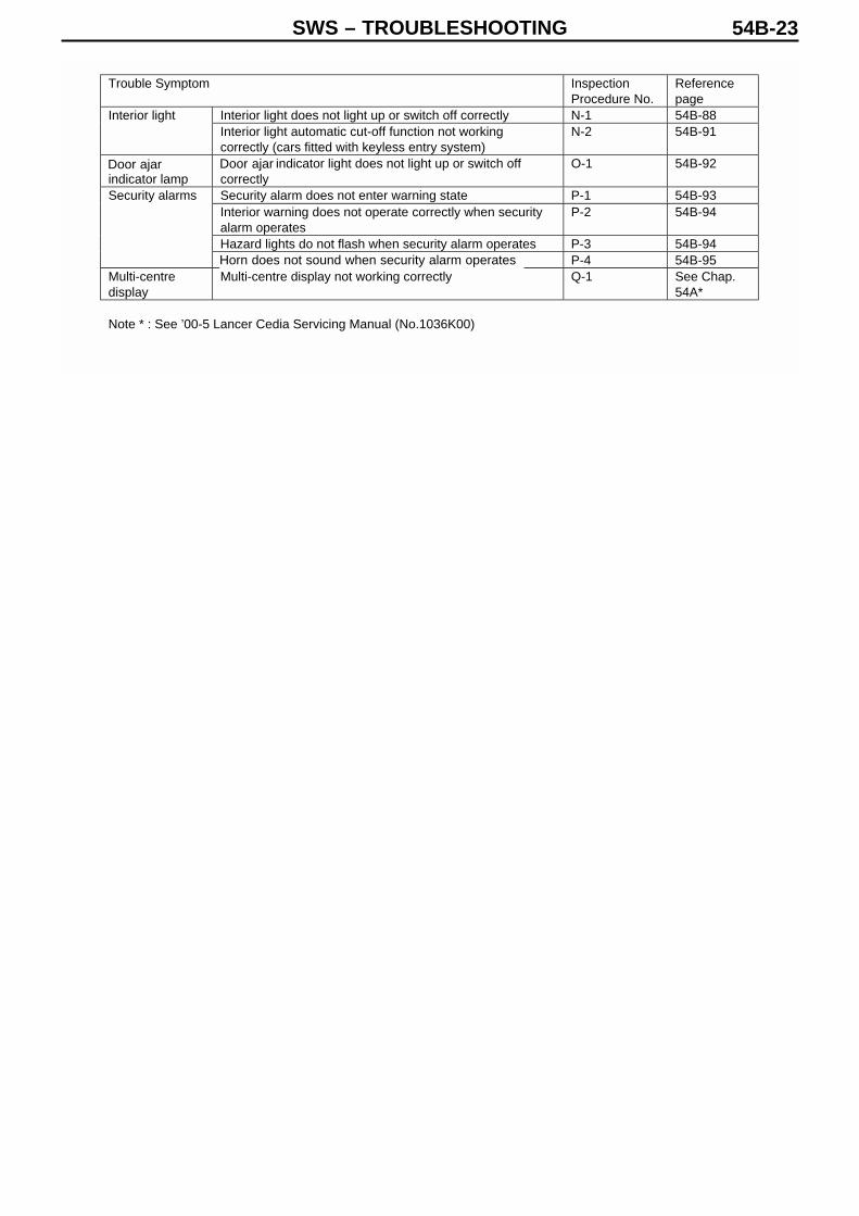
SWS – TROUBLESHOOTING 54B-23
Trouble Symptom InspectionProcedure No.
Referencepage
Interior light does not light up or switch off correctly N-1 54B-88Interior lightInterior light automatic cut-off function not workingcorrectly (cars fitted with keyless entry system)
N-2 54B-91
Half doorindicator lamp
Half door indicator light does not light up or switch offcorrectly
O-1 54B-92
Security alarm does not enter warning state P-1 54B-93Interior warning does not operate correctly when securityalarm operates
P-2 54B-94
Hazard lights do not flash when security alarm operates P-3 54B-94
Security alarms
Phone does not ring when security alarm operates P-4 54B-95Multi-centredisplay
Multi-centre display not working correctly Q-1 See Chap.54A*
Note * : See ’00-5 Lancer Cedia Servicing Manual (No.1036K00)
Door ajar Door ajar
Horn does not sound when security alarm operates
SWS – TROUBLESHOOTING54B-24
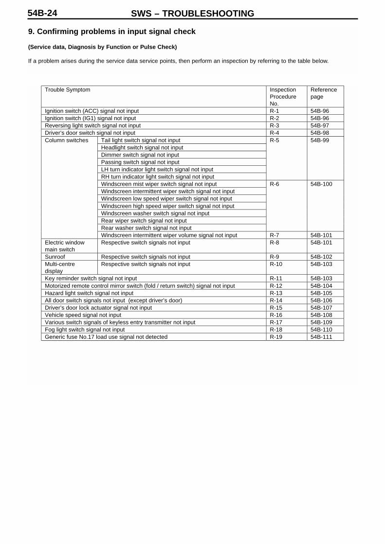
9. Confirming problems in input signal check
(Service data, Diagnosis by Function or Pulse Check)
If a problem arises during the service data service points, then perform an inspection by referring to the table below.
Trouble Symptom InspectionProcedureNo.
Referencepage
Ignition switch (ACC) signal not input R-1 54B-96Ignition switch (IG1) signal not input R-2 54B-96Reversing light switch signal not input R-3 54B-97Driver’s door switch signal not input R-4 54B-98
Tail light switch signal not inputHeadlight switch signal not inputDimmer switch signal not inputPassing switch signal not inputLH turn indicator light switch signal not inputRH turn indicator light switch signal not input
R-5 54B-99
Windscreen mist wiper switch signal not inputWindscreen intermittent wiper switch signal not inputWindscreen low speed wiper switch signal not inputWindscreen high speed wiper switch signal not inputWindscreen washer switch signal not inputRear wiper switch signal not inputRear washer switch signal not input
R-6 54B-100
Column switches
Windscreen intermittent wiper volume signal not input R-7 54B-101Electric windowmain switch
Respective switch signals not input R-8 54B-101
Sunroof Respective switch signals not input R-9 54B-102Multi-centredisplay
Respective switch signals not input R-10 54B-103
Key reminder switch signal not input R-11 54B-103Motorized remote control mirror switch (fold / return switch) signal not input R-12 54B-104Hazard light switch signal not input R-13 54B-105All door switch signals not input (except driver’s door) R-14 54B-106Driver’s door lock actuator signal not input R-15 54B-107Vehicle speed signal not input R-16 54B-108Various switch signals of keyless entry transmitter not input R-17 54B-109Fog light switch signal not input R-18 54B-110Generic fuse No.17 load use signal not detected R-19 54B-111

SWS – TROUBLESHOOTING 54B-25
Chart of operational functions classified by input signal inspection procedure number
If a problem arises in a number of different functions when using the SWS, perform an input signal check by referring to thetable below.(Only the input signals and functions which may possibly give rise to multiple problems are listed in the table)
Name of function R-1 R-2 R-3 R-4 R-5 R-6 R-11 R-13 R-14 R-15 R-16 R-17 R-19
Ignition key left in reminder warning
Lights left on reminder warning
Door ajar warning function
Turn indicator light operating noise
Central door locking control
Keyless entry
Keyless entry answer back
Multi-mode keyless entry
Electric window control
Electric window timer
Sunroof control
Windscreen wiper & washer control
Rear wiper & washer control
Motorized retractable door mirror control
Ignition key cylinder illumination light control
Tail light control
Headlight control
Headlight automatic cut-off
Fog light control
Turn indicator light control
Hazard light control
Interior light control
Interior light automatic cut-off
Door ajar indicator lamp
Security alarm

SWS – TROUBLESHOOTING54B-26
10. Inspection Procedures Classified by Trouble Symptoms
Inspection Procedure
Can the MUT-II/III communicate with other systems?
Is communication with the MUT-II/III possible when theignition switch is set to the ON position?
Check connector C-225
Measure at ETACS-ECU connector C-225• Detach the connector, and measure at the junction box
side• Connectivity between 56 and body earth
OK: No connectivity
Check connectors C-06, C-122
Check the harness between the ETACS-ECU and thediagnosis connectors
Confirm the trouble symptoms
Transient problem
Check MUT-II/III diagnosis circuit, and repair
Inspection procedure A-3 “No communication withETACS-ECU”. See p.54B-28
Check connector C-107
Check the harness between the ETACS-ECU and bodyearth
Replace the ETACS-ECU
No communication with SWS monitor Probable CauseThere may be a malfunction in the connections to the SWSmonitor
• Fault in SWS monitor main unit (I/F cartridge)• Fault in SWS monitor harness• Fault in harness / connectors• Fault in ETACS-ECU
YES
NO
NO
YES
NG
NG
NG
NG
OK
OK
OK
OK
OK
NG
Repair
OK NG
Repair
Repair
Repair

SWS – TROUBLESHOOTING 54B-27
SWS monitor ECU check• Ignition switch : OFF
ETACS-ECU OK: “OK” is displayed
Check connectors C-203
Measure at the Column switch connector C-203• Detach the connector and measure at the harness side• Voltage between 1 and body earth
OK: Battery voltage
Measure at the Column switch connector C-203• Detach the connector and measure at the harness side• Connectivity between 4 and body earth
OK: Connectivity
Check connector C-225
Check the harness between the ETACS-ECU and thecolumn switch (request line)
SWS monitor ECU check• Ignition switch : OFF
Column ECU (column switch)OK: “OK” is displayed
Transient problem
To Inspection procedure A-3 No communication withETACS-ECU (see p.54B-28)
Check connectors C-07, C-209
Check the harness between the column switch and thejunction box, and repair
Check connector C-107
Check the harness between the column switch and thebody earth, and repair
Replace the column switch
Inspection Procedure A-2
No communication with column switch (column ECU) Probable Cause
There may be a problem in the column switch (column ECU)power supply circuit system.If there is a problem in the harness of the ECU battery powersupply circuit (column switch terminal No.1), then the ignitionswitch (IG1) power supply circuit (column switch terminalNo.9) should also be checked and repaired at the same time.
• Fault in column switch• Fault in harness or connectors
OK
NG
NG
NG
NG
NG
NG
NG
OK
OK
OK
OK
OK
OK
OK NG
OK NG
Repair
Repair
Repair
Repair
Repair

SWS – TROUBLESHOOTING54B-28
Inspection Procedure A-3
No communication with ETACS-ECU Probable Cause
There may be an abnormality in the power supply circuit of the ETACS-ECU or a problem in the harness or connectors between the SWS monitorand the ETACS-ECU. In the event of an abnormality in the harness of theECU battery power supply (ETACS-ECU terminal No.20), the ignitionswitch (IG1) power supply circuit (ETACS-ECU terminal No.8) should bechecked and repaired at the same time. Furthermore, in the event of anabnormality in the harness of the ECU earth circuit (ETACS-ECU terminalNo.3), the centre earth circuit (ETACS-ECU terminal No.56) should bechecked and repaired at the same time.
• Fault in ETACS-ECU• Fault in harness or connectors
Check connectors C-224
Measure at the ETACS-ECU connector C-224• Detach the connector and measure at the junction box
side• Voltage between 20 and body earthOK: Battery voltage
Measure at the ETACS-ECU connector C-224• Detach the connector and measure at the junction box side• Connectivity between 3 and body earthOK: Connectivity
Check connectors C-119, C-203, C-225
Check the harness between the ETACS-ECU and thecolumn switch (SWS)
SWS monitor ECU check• Ignition switch : OFF
ETACS-ECU OK: “OK” is displayed
Transient problem
Check connectors C-32, C-211
Check the harness between the ETACS-ECU and thefusible link, and repair
Check connector C-212
Check the harness between the ETACS-ECU and thebody earth, and repair
Replace the ETACS-ECU
OK
OK
OK
OK
OK
OK
OK
OK
NG
NG
NG
NG
NG
NG
NG
NGRepair
Repair
Repair
Repair
Repair

SWS – TROUBLESHOOTING 54B-29
SWS monitor ECU check• Ignition switch : OFFETACS-ECU OK: “OK” is displayed
Measure at the Front ECU connector A-12X• Detach the connector and measure at the relay box
side• Voltage between 7 and body earthOK: Battery voltage
Check connector A-13X
Measure at the Front ECU connector A-13X• Detach the connector and measure at the relay box
side• Connectivity between 31 and body earthOK: Connectivity
Check connectors C-31, C-119, C-203
Check the harness between the front ECU and thecolumn switch (SWS)
SWS monitor ECU check• Ignition switch : OFFFront ECUOK: “OK” is displayed
Transient problem
To Inspection procedure A-3 No communication withETACS-ECU (see p.54B-28)
Check connectors C-07, C-31, C-209
Check the harness between the front ECU and thejunction box, and repair
Check the harness between the front ECU and the bodyearth, and repair
Replace the front ECU
Check connector A-12X
Inspection Procedure A-4
No communication with front ECU Probable Cause
There may be an abnormality in the front ECU power supply circuit system, or aproblem the harness and connectors between the SWS monitor and the frontECU. In the event of an abnormality in the harness of the ECU battery powersupply circuit (Front ECU terminal No.7), the ignition switch (IG2) power supplycircuit (front ECU terminal No.30) at the same time.
• Fault in front ECU• Fault in harness or connectors
NG
NG
NG
NG
NG
NG
NG
NG
NG
OK
OK
Repair
Repair
Repair
Repair
Repair
OK
OK
OK
OK
OK
OK
OK
SWS – TROUBLESHOOTING54B-30
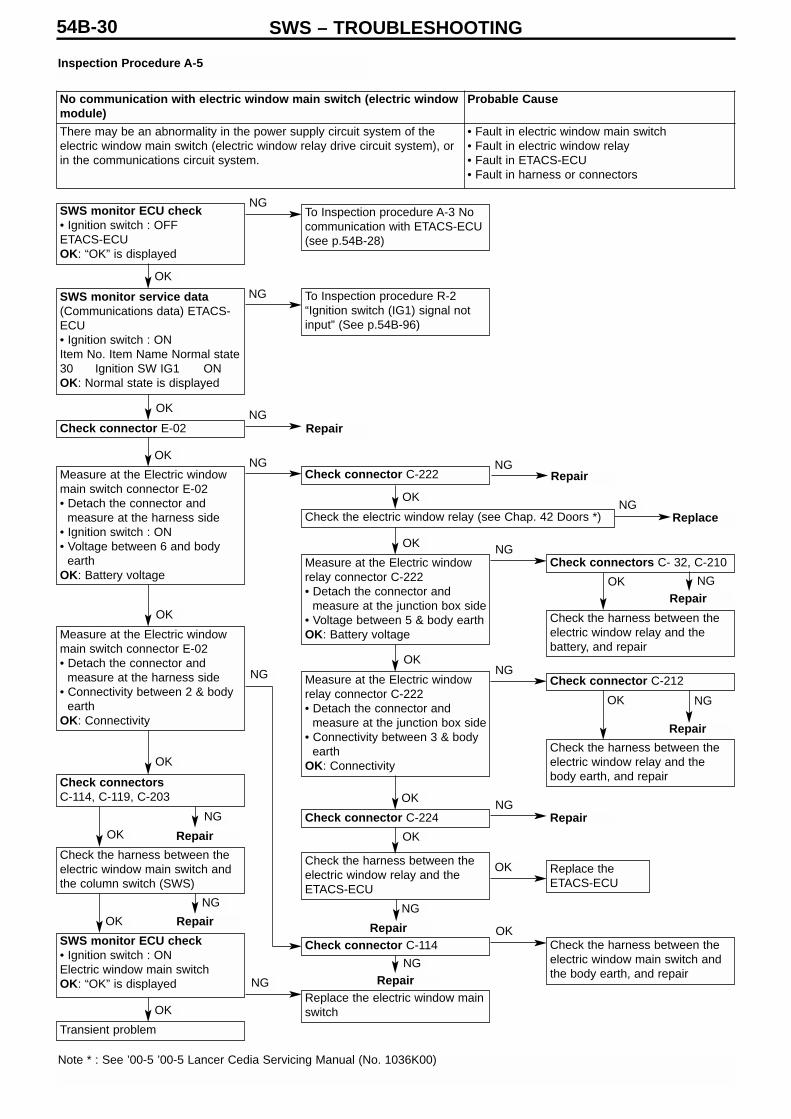
Inspection Procedure A-5
SWS monitor ECU check• Ignition switch : OFFETACS-ECU OK: “OK” is displayed
SWS monitor service data(Communications data) ETACS-ECU• Ignition switch : ONItem No. Item Name Normal state30 Ignition SW IG1 ONOK: Normal state is displayed
Check connector E-02
Measure at the Electric windowmain switch connector E-02• Detach the connector and
measure at the harness side• Ignition switch : ON• Voltage between 6 and body
earthOK: Battery voltage
Measure at the Electric windowmain switch connector E-02• Detach the connector and
measure at the harness side• Connectivity between 2 & body
earthOK: Connectivity
Check connectorsC-114, C-119, C-203
Check the harness between theelectric window main switch andthe column switch (SWS)
SWS monitor ECU check• Ignition switch : ONElectric window main switchOK: “OK” is displayed
Transient problem
To Inspection procedure A-3 Nocommunication with ETACS-ECU(see p.54B-28)
To Inspection procedure R-2“Ignition switch (IG1) signal notinput” (See p.54B-96)
Check connector C-222
Measure at the Electric windowrelay connector C-222• Detach the connector and
measure at the junction box side• Voltage between 5 & body earthOK: Battery voltage
Measure at the Electric windowrelay connector C-222• Detach the connector and
measure at the junction box side• Connectivity between 3 & body
earthOK: Connectivity
Check connector C-224
Check the harness between theelectric window relay and theETACS-ECU
Check connector C-114
Replace the electric window mainswitch
Check connectors C- 32, C-210
Check the harness between theelectric window relay and thebattery, and repair
Check connector C-212
Check the harness between theelectric window relay and thebody earth, and repair
Check the harness between theelectric window main switch andthe body earth, and repair
Replace theETACS-ECU
Check the electric window relay (see Chap. 42 Doors *)
Note * : See ’00-5 ’00-5 Lancer Cedia Servicing Manual (No. 1036K00)
No communication with electric window main switch (electric windowmodule)
Probable Cause
There may be an abnormality in the power supply circuit system of theelectric window main switch (electric window relay drive circuit system), orin the communications circuit system.
• Fault in electric window main switch• Fault in electric window relay• Fault in ETACS-ECU• Fault in harness or connectors
NG
NG
NG
NG
NG
NG
NG
NG
NG
NG
NG
NG
NG
NG
OK
NG
NG
Repair
Repair
Replace
Repair
Repair
Repair
Repair
Repair
Repair
Repair
NG
OK
OK
OK
OK
OK
OK
OK
OK
OK
OK
OK
OK
OK
OK
OK
OK

SWS – TROUBLESHOOTING 54B-31
Inspection Procedure A-6
Check connectors D-27
Measure at the Sunroof motor assembly connector D-27• Detach the connector and measure at the harness side• Voltage between 1 and body earthOK: Battery voltage
Measure at the Sunroof motor assembly connector D-27• Detach the connector and measure at the harness side• Ignition switch : ON• Voltage between 2 and body earthOK: Battery voltage
Measure at the Sunroof motor assembly connector D-27• Detach the connector and measure at the harness side• Connectivity between 5 and body earthOK: Connectivity
Check connectors C-113, C-119, C-203
Check the harness between the sunroof motor assemblyand the column switch
SWS monitor ECU check• Ignition switch : OFF
Sunroof ECUOK: “OK” is displayed
Check connectors C-32, C-113, C-223
Check the harness between the sunroof motor assemblyand the battery, and repair
Check connectors C-210, C-216
Check the harness between the sunroof motor assemblyand the junction box, and repair
Check the harness between the sunroof motor assemblyand the body earth, and repair
Transient problem
Replace the sunroof motor assembly
No communication with sunroof motor assembly Probable CauseThere may be an abnormality in the communications circuit system or the powersupply circuit system of the sunroof motor assembly
• Fault in sunroof motor assembly• Fault in harness or connectors
OK
OK
OK
OK
OK
OK
OK
OK
NG
NG
NG
NG
NG
Repair
Repair
Repair
Repair
Repair
NG
NG
NG
NG
OK
SWS – TROUBLESHOOTING54B-32
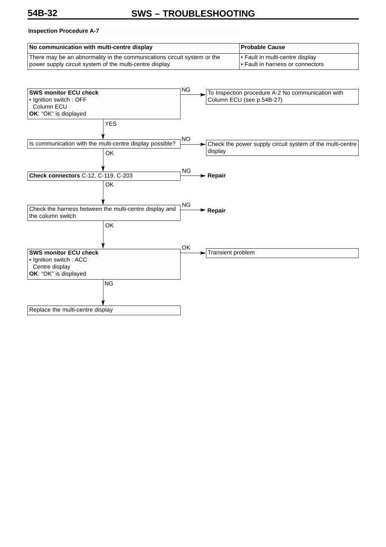
Inspection Procedure A-7
SWS monitor ECU check• Ignition switch : OFF
Column ECU OK: “OK” is displayed
Is communication with the multi-centre display possible?
Check connectors C-12, C-119, C-203
Check the harness between the multi-centre display andthe column switch
SWS monitor ECU check• Ignition switch : ACC
Centre displayOK: “OK” is displayed
To Inspection procedure A-2 No communication withColumn ECU (see p.54B-27)
Check the power supply circuit system of the multi-centredisplay
Transient problem
Replace the multi-centre display
No communication with multi-centre display Probable Cause
There may be an abnormality in the communications circuit system or thepower supply circuit system of the multi-centre display
• Fault in multi-centre display• Fault in harness or connectors
YES
OK
OK
OK
NG
NG
NGRepair
Repair
NO
NG
OK

SWS – TROUBLESHOOTING 54B-33
SWS monitor ECU check• Ignition switch : OFF
ETACS-ECU OK: “OK” is displayed
SWS monitor service data(Diagnosis by Function) Buzzer : Remove key reminderbuzzer• Ignition switch : OFF (key inserted)• Driver’s door : openItem No. Item Name Normal state(a) 30 Ignition SW IG1 OFF(b) 32 Driver door SW RH ON(c) 43 Buzzer ONOK: All display normal state
Confirm the trouble symptoms
Transient problem
To Inspection procedure A-3 No communication withETACS-ECU (see p.54B-28)
To Inspection procedure R-2 “Ignition switch (IG1) signalnot input” (See p.54B-96)
To Inspection procedure R-4 “Driver’s door switch signalnot input” (See p.54B-98)
To Inspection procedure R-11 “Key reminder switchsignal not input” (See p.54B-103)
Replace the ETACS-ECU
Replace the ETACS-ECU
SWS monitor service dataETACS switch data• Ignition switch : OFF (key inserted)Item No. Item Name Normal state03 Key reminder SW OFFOK: Displays normal state
Inspection Procedure B-1
Ignition key left in reminder function not working correctly Probable Cause
This function is operated by determining the following input signals in theETACS-ECU.• Ignition switch (IG1)• Key reminder switch• Driver’s door switchIf the function is not working properly, then there is probably a problem in theinput circuit system for these signals, or a malfunction in the ETACS-ECU.
• Fault in key reminder switch• Fault in driver’s door switch• Fault in ETACS-ECU• Fault in harness or connectors
OK
OK
OK
OK
NG (a)
NG (b)
NG (c)
NG
NG
NG
SWS – TROUBLESHOOTING54B-34
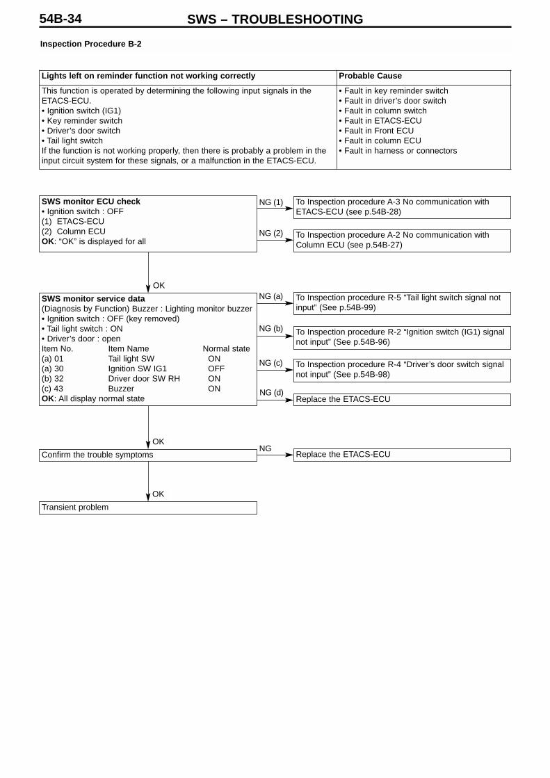
Inspection Procedure B-2
SWS monitor ECU check• Ignition switch : OFF(1) ETACS-ECU (2) Column ECUOK: “OK” is displayed for all
Confirm the trouble symptoms
Transient problem
To Inspection procedure A-3 No communication withETACS-ECU (see p.54B-28)
To Inspection procedure A-2 No communication withColumn ECU (see p.54B-27)
To Inspection procedure R-5 “Tail light switch signal notinput” (See p.54B-99)
To Inspection procedure R-2 “Ignition switch (IG1) signalnot input” (See p.54B-96)
To Inspection procedure R-4 “Driver’s door switch signalnot input” (See p.54B-98)
Replace the ETACS-ECU
Replace the ETACS-ECU
SWS monitor service data(Diagnosis by Function) Buzzer : Lighting monitor buzzer• Ignition switch : OFF (key removed)• Tail light switch : ON• Driver’s door : openItem No. Item Name Normal state(a) 01 Tail light SW ON(a) 30 Ignition SW IG1 OFF(b) 32 Driver door SW RH ON(c) 43 Buzzer ONOK: All display normal state
Lights left on reminder function not working correctly Probable Cause
This function is operated by determining the following input signals in theETACS-ECU.• Ignition switch (IG1)• Key reminder switch• Driver’s door switch• Tail light switchIf the function is not working properly, then there is probably a problem in theinput circuit system for these signals, or a malfunction in the ETACS-ECU.
• Fault in key reminder switch• Fault in driver’s door switch• Fault in column switch• Fault in ETACS-ECU• Fault in Front ECU• Fault in column ECU• Fault in harness or connectors
OK
OK
OK
NG
NG (d)
NG (c)
NG (b)
NG (a)
NG (1)
NG (2)
SWS – TROUBLESHOOTING 54B-35
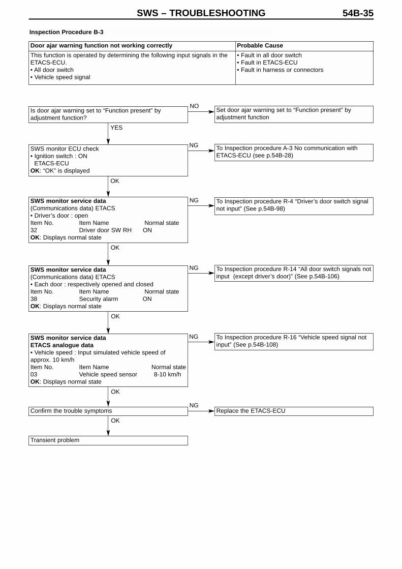
Is door ajar warning set to “Function present” byadjustment function?
SWS monitor ECU check• Ignition switch : ON
ETACS-ECU OK: “OK” is displayed
SWS monitor service data(Communications data) ETACS• Driver’s door : openItem No. Item Name Normal state32 Driver door SW RH ONOK: Displays normal state
SWS monitor service data(Communications data) ETACS• Each door : respectively opened and closedItem No. Item Name Normal state38 Security alarm ONOK: Displays normal state
SWS monitor service dataETACS analogue data• Vehicle speed : Input simulated vehicle speed ofapprox. 10 km/hItem No. Item Name Normal state03 Vehicle speed sensor 8-10 km/hOK: Displays normal state
Confirm the trouble symptoms
Transient problem
Set door ajar warning set to “Function present” byadjustment function
To Inspection procedure A-3 No communication withETACS-ECU (see p.54B-28)
To Inspection procedure R-4 “Driver’s door switch signalnot input” (See p.54B-98)
To Inspection procedure R-14 “All door switch signals notinput (except driver’s door)” (See p.54B-106)
To Inspection procedure R-16 “Vehicle speed signal notinput” (See p.54B-108)
Replace the ETACS-ECU
Inspection Procedure B-3
Door ajar warning function not working correctly Probable Cause
This function is operated by determining the following input signals in theETACS-ECU.• All door switch • Vehicle speed signal
• Fault in all door switch• Fault in ETACS-ECU• Fault in harness or connectors
YES
NO
NG
NG
NG
NG
NG
OK
OK
OK
OK
OK

SWS – TROUBLESHOOTING54B-36
nspection Procedure B-4
Is the turn indicator operating noise function set to“Function present” by the adjustment function?
SWS monitor ECU check• Ignition switch : ON(1) Column ECU(2) ETACS-ECU OK: “OK” is displayed for all
SWS monitor service data(Diagnosis by Function) Turn indicator light : R Turnindicator • Turn indicator light switch : RH• Ignition switch : ONItem No. Item Name Normal state(a) 10 RH turn indicator SW ON(b) 30 Ignition SW IG1 ONOK: All display normal state
SWS monitor service data(Diagnosis by Function) Turn indicator light : L Turnindicator • Turn indicator light switch : LH• Ignition switch : ONItem No. Item Name Normal state(a) 11 LH turn indicator SW ONOK: Displays normal state
Confirm the trouble symptoms
Transient problem
Set the turn indicator operating noise function to“Function present” by the adjustment function
To Inspection procedure A-2 No communication withColumn ECU (see p.54B-27)
To Inspection procedure A-3 No communication withETACS-ECU (see p.54B-28)
To Inspection procedure R-5 “Column switches Lighting,Turn indicator light switch) signal not input” (See p.54B-99)
To Inspection procedure R-2 “Ignition switch (IG1) signalnot input” (See p.54B-96)
To Inspection procedure R-5 “Column switches Lighting,Turn indicator light switch) signal not input” (See p.54B-99)
Replace the ETACS-ECU
Turn indicator light operating noise not working correctly Probable Cause
This function is operated by determining the following input signals in theETACS-ECU.• Turn indicator light switch• Hazard light switch
• Fault in column switch• Fault in ETACS-ECU• Fault in harness or connectors
YES
NO
NG (1)
NG (2)
NG (a)
NG (b)
NG
NG
OK
OK
OK
OK

SWS – TROUBLESHOOTING 54B-37
Is the multi-centre display working normally?
SWS monitor ECU check(1) ETACS-ECU (2) Centre displayOK: “OK” is displayed for all
SWS monitor service data(Diagnosis by Function) Buzzer : Display buzzer• Ignition switch : ON• Radio memory operation has been performedItem No. Item Name Normal state(a) 60 beep data ON (2kHz)(b) 43 Buzzer OFFOK: All display normal state
Confirm the trouble symptoms
Transient problem
Check the multi-centre display (See Chap. 54A –MMCS*)
To Inspection procedure A-3 No communication withETACS-ECU (see p.54B-28)
To Inspection procedure A-7 No communication withMulti-centre display (see p.54B-32)
To Inspection procedure R-10 “Respective switch signalsof multi-centre display not input” (See p.54B-103)
Replace the ETACS-ECU
Replace the ETACS-ECU
Inspection Procedure B-5
Note :(1) When performing the SWS monitor service data check, confirm at the same time that the 60 beep data state changes
momentarily from “OFF” to the normal state when the image operating switch is activated. (2) *: See ’00-5 Lancer Cedia Servicing Manual (No. 1036K00)
Multi-centre display operating noise function not working correctly Probable CauseA buzzer sounds when the ETACS-ECU receives a sound request signalfrom the multi-centre display.If this function does not work correctly, then this is probably due to anabnormality in the communications circuit, a fault in the multi-centredisplay, or a fault in the ETACS-ECU.
• Fault in multi-centre display• Fault in ETACS-ECU• Fault in harness or connectors
OK
NG
NG (1)
NG (a)
NG (b)
NG
NG (2)
OK
OK
OK

SWS – TROUBLESHOOTING54B-38
Inspection Procedure C-1
SWS monitor ECU check• Ignition switch : OFF
ETACS-ECU OK: “OK” is displayed for all
Check connector E-03
Check driver’s door lock actuator (See Chap. 42 Doors)
Check connectors C-224, C-211, C-32
Check the harness between the ETACS-ECU and thefusible link (1)
Confirm the trouble symptoms
Transient problem
To Inspection procedure A-3 No communication withETACS-ECU (see p.54B-28)
To Inspection procedure R-15 Driver’s door lock actuatorsignal not input (See p.54B-107)
Replace the ETACS-ECU
SWS monitor service dataETACS switch data• Driver’s door : Unlock → lockItem No. Item Name Normal state(1) 21 Dr Door lock SW OFF → ON(2) 22 Dr Door unlock SW ON → OFFOK: All display normal state
Central door locking not working at all Probable Cause
The ETACS-ECU locks or unlocks all the doors by activating all of the doorlock actuators, when there is a change in the input signal from the driver’s doorlock actuator.If this function does not work properly, then there is probably a fault in thedriver’s door lock actuators or a fault in the ETACS-ECU.
• Fault in driver’s door lock actuator• Fault in ETACS-ECU• Fault in harness or connectors
OK
OK
OK
OK
OK
OK
OK
NG
Repair
Repair
Replace
Repair
NG
NG
NG
NG
NG
NG

SWS – TROUBLESHOOTING 54B-39
Check connectors (Driver’s door) E-03, (Frontpassenger door) E-10, (Left-side rear door) E-106,(Right-side rear door) E-103
Check door lock actuators of doors that are not working(see Chap. 42 Doors)
Check connectors (Driver’s door) C-226, C-114(Front passenger door) C-224, C-212, C-33(Left-side rear door) C-224, C-212, C-29, D-13(Right-side rear door) C-224, C-215, D-03
Check the harness between the ETACS-ECU and thedock lock actuators of the doors that are not working,and repair
Inspection Procedure C-2
Some doors not operating, even when lock or unlock is performed Probable Cause
There is probably a fault in the door lock actuator of the door(s) which are notworking.
• Fault in door lock actuator• Fault in harness or connectors
NGRepair
Replace
Repair
OK
OK
OK
NG
NG

SWS – TROUBLESHOOTING54B-40
Inspection Procedure D-1
SWS monitor ECU check• Ignition switch : ON(1) ETACS-ECU(2) Electric window moduleOK: “OK” is displayed for all
SWS monitor service dataETACS switch data• Driver’s door : Unlock → lockItem No. Item Name Normal state(a) 30 Ignition SW IG1 ON(b) 33 P/W SW enabled Enabled(c) 71 P/W module response Input check*OK: All display normal state
SWS monitor service data(Communications data) Door-to-door communications • Insert probe at probe position in door-to-door
communications line. See p.54B-6 for probe position.• Ignition switch : ON• Electric window main switch : UPItem No. Item Name Normal stateC0 Driver window UP ONOK: All display normal state
Check the harness between the respective electricwindow motor assemblies and the electric window mainswitch, and repair
To Inspection procedure A-3 No communication withETACS-ECU (see p.54B-28)
To Inspection procedure A-5 No communication withelectric window main switch (electric window module)p.54B-30
Go to Inspection procedure R-2 Ignition switch (IG1)signal not input (p.54B-96)
Replace the ETACS-ECU
Replace the electric window main switch
Replace the electric window main switch
Note :*: Also check that the “Normal response” changes momentarily to “Input check” when the electric window main switch isoperated.
None of electric windows working Probable Cause
This is probably due to a fault in the electric window relay, a fault in the electricwindow main switch or a fault in the ETACS-ECU.
• Fault in electric window main switch• Fault in ETACS-ECU • Fault in harness or connectors
OK
OK NG
OK
NG (1)
NG (2)
NG (a)
NG (b)
NG (c)

SWS – TROUBLESHOOTING 54B-41
Can the front passenger or rear passenger electricwindows all be operated with the electric window mainswitch?
Check connectors E-02, E-04
Check the harness between the electric window motorassembly (front : RH) and the electric window mainswitch
Confirm the trouble symptoms
Transient problem
Go to Inspection procedure D-1 None of electric windowsworking
Replace the electric window main switch
Replace the electric window motor assembly (front : RH)
SWS monitor service data check(Communications data) Door-do-door communications • Insert probe at probe position in door-to-doorcommunications line. See p.54B-6 for probe position.• Ignition switch : ON• Do the following normal states appear when the electricwindow main switch is operatedItem No. Item Name Normal stateC0 Front passenger window UP ONC1 Front passenger window DOWN ONC2 Front passenger window AUTO ON
OK: All display normal state
Inspection Procedure D-2
Driver’s electric window not responding to electric window mainswitch
Probable Cause
There is probably a fault in the electric window main switch or the driver’selectric window motor.
• Fault in electric window main switch• Fault in driver’s electric window motor assembly• Fault in harness or connectors
YES
NO
NG
NG
NG
NG
Repair
Repair
OK
OK
OK
OK

SWS – TROUBLESHOOTING54B-42
Inspection Procedure D-3
Is the lock switch of the electric window main switchturned off?
SWS monitor service data check(Communications data) Door-do-door communications • Insert probe at probe position in door-to-door
communications line. See p.54B-6 for probe position.• Ignition switch : ON• Electric window main switch lock : OFFItem No. Item Name Normal stateCB P/W LOCK SW OFF
OK: All display normal state
Do any of the electric windows respond to theirswitches?NG: (1) Front LH electric window not working
(2) Rear : RH electric window not working(3) Rear : LH electric window not working
Measure at Electric window sub switch (front : LH) connector E-06• Detach the connector and measure at the
harness side• Ignition switch : ON(1) Voltage between 4 & body earth
OK: Battery voltage(2) Connectivity between 1 & body earth
OK: Connectivity
Measure at Electric window motor (front :LH) connector E-09• Detach the connector and measure at the
harness side• Connectivity between 5 & body earthOK: Connectivity
Check the harness between the electricwindow motor (front : LH) and the electricwindow sub switch (front : LH)
Check connectors E-09
To next page
Turn off the lock switch of the electric window mainswitch
Replace the electric window main switch
Check connector E-06
Check electric window sub switch (front : LH) (see Chap.42 Doors *)
Check connectors C-210, C-33
Check the harness between the electric window subswitch (front : LH) & junction box, and repair
Check connector C-33
Check the harness between the electric window subswitch (front : LH) & body earth, and repair
Check connector C-33
Check the harness between the electric window motor(front : LH) and the body earth, and repair
Confirm the trouble symptoms
Replace the electric window motor assembly (front LH)
Note * : See ’00-5 Lancer Cedia Servicing Manual (No. 1036K00)
Front passenger’s or rear passenger’s electric windows notresponding to their respective switches
Probable Cause
There is probably a fault in the electric window sub switch or the front orrear passenger electric window motor.
• Fault in electric window sub switch• Fault in front or rear passenger electric window
motor assembly• Fault in harness or connectors
YES
NO
NG
NG (1)
NG (1)
NG (2)
NG (2)
NG (3)
OK
OK
OK
OK
OK
OK
OK
OK
NG NG
NG
NG
NG
NG
NG
NG
OKOK
NG
Repair
Repair
Repair
Repair
Replace
Repair
Repair

SWS – TROUBLESHOOTING 54B-43
From previous page
Check connectors C-210, D-03
Check the harness between the electric window subswitch (rear: RH) and the junction box, and repair
Check connector D-03
Check the harness between the electric window subswitch (rear: RH) and the body earth, and repair
Check connector D-03
Check the harness between the electric window motor(rear: RH) and the body earth, and repair
Confirm the trouble symptoms
Replace the electric window module assembly (rear :RH)
Check connectors C-210, D-03
Check the harness between the electric window subswitch (rear: LH) and the junction box, and repair
Check connector D-13
Check the harness between the electric window subswitch (rear: LH) and the body earth, and repair
Check connector E-102
Check the electric window sub switch (rear :RH) (see Chap. 42 Doors *)
Check connector E-101
Check connector E-105
Check the electric window sub switch (rear :LH) (see Chap. 42 Doors *)
To Next page
Measure at Electric window sub switch (rear : LH) connector E-105• Detach the connector and measure at the
harness side• Ignition switch : ON(1) Connectivity between 4 & body earth
OK: Battery voltage (2) Connectivity between 1 & body earth
OK: Connectivity
Measure at Electric window motor (rear : RH) connector E-101• Detach the connector and measure at the
harness side• Connectivity between 5 & body earthOK: Connectivity
Check the harness between the electricwindow motor (rear : RH) and the powerwidow sub-switch (rear : RH)
Measure at Electric window sub switch (rear : RH) connector E-102• Detach the connector and measure at the
harness side• Ignition switch : ON(1) Connectivity between 4 & body earth
OK: Battery voltage (2) Connectivity between 1 & body earth
OK: Connectivity
Note * : See ’00-5 Lancer Cedia Servicing Manual (No. 1036K00)
NG (2)
Repair
Replace
Repair
NG (3)
OK
NG (2)
NG
NG
NG (1)OK
OK
OK
OK
OK
OK
OK
OK
OK
OK
NG
NG
NG
NG
NG
NG
NG
NG
NG
NG
OK
OK
NG
NG (2)
NG (1)
NG
Repair
Repair
Repair
Repair
Repair
Repair
Repair
Replace

SWS – TROUBLESHOOTING54B-44
From previous page
Check connector D-13
Check the harness between the electric window motor(rear: LH) and the body earth, and repair
Confirm the trouble symptoms
Replace the electric window module assembly (rear : LH)
Check connectors E-104
Measure at Electric window motor (rear :LH) connector E-104• Detach the connector and measure at the
harness side• Ignition switch : ON(1) Connectivity between 5 & body earthOK: Connectivity
Check the harness between the electricwindow motor (rear : LH) and the powerwidow sub-switch (rear : LH)
OK
OK
OK
OK
NG
NG
OK
NG
NG
Repair
Repair

SWS – TROUBLESHOOTING 54B-45
Inspection procedure D-4
Do the electric windows respond to their respectiveelectric window sub switches?
SWS monitor ECU check• Ignition switch: ONP/W moduleOK: “OK” is displayed
Check connectors Between probe insertion point andelectric window sub switch at the door where the windowis not working
To Inspection procedure D-3 Front passenger’s or rearpassenger’s electric windows not responding to theirrespective switches (p.54B-42)
To Inspection procedure A-5 No communication withelectric window main switch (electric window module)(p.54B-30)
Check connectors Probe insertion point – E-02
Check the harness between the probe insertion point andthe electric window main switch
Confirm the trouble symptoms
Transient problem
Replace the electric window sub switch of the doorwhere the window is not working
Replace the electric window main switch
Check the harness between probe connection point andthe electric window sub switch at the door where thewindow is not working
Confirm the trouble symptoms
Transient problems
SWS monitor service data check(Communications data) Door-do-door communications • Insert probe between the electric window main switch
and the electric window sub switch of the door whoseelectric window does not operate with the electricwindow main switch. See p.54B-6 for probe position.
• Ignition switch: ON• Are the following normal states displayed when the
respective electric window switches of the electricwindow main switch are operated?
Item No. Item Name Normal state(a) C0 Front passenger window LH UP ON(b) C1 Front passenger window LH DOWN ON(c) C2 Front passenger window LH AUTO ON(d) C4 Rear RH UP ON(e) C5 Rear RH DOWN ON(f) C6 Rear RH AUTO ON(g) C8 Rear LH UP ON(h) C9 Rear LH DOWN ON(i) CA Rear LH AUTO ONOK: All display normal state
Front and/or rear passenger electric window notresponding to electric window main switch
Probable Cause
There is probably a fault in the electric window main switch orthe front or rear passenger electric window sub switch
• Fault in electric window main switch• Fault in front or rear passenger electric window sub switch• Fault in harness or connectors
NG(All a-i)
NG Any ofa-i)
YES
NO
OK
OK
OK
OK
OK
OK
NG
NG
NG
NG
NG
NG
Repair
Repair
OK
OK
Repair
Repair
NG

SWS – TROUBLESHOOTING54B-46
Inspection procedure D-5
SWS monitor ECU check• Ignition switch: ON → OFF(1) ETACS-ECU (2) P/W moduleOK: “OK” is displayed for all
SWS monitor service data check(Diagnosis by Function) Electric windows• Ignition switch: ON → OFF Item No. Item Name Normal state(a) 30 Ignition SW IG1 OFF(b) 33 P/W SW enable Enabled *1
(c) 71 P/W module response Input check *2
OK: All display normal state
Confirm the trouble symptoms
Transient problem
To Inspection procedure A-3 No communication withETACS-ECU (p.54B-28)
To Inspection procedure A-5 No communication withelectric window main switch (electric window module)(p.54B-30)
To Inspection procedure R-2 Ignition switch (IG1)signal not input (p.54B-96)
Replace the ETACS-ECU
Replace the electric window main switch
Replace the electric window main switch
Note:(1) When performing the SWS monitor check, in analyzing the electric window main switch (electric window module), “OK” is
displayed for about 1 min. and then the display changes to “NG”. However, the ETACS-ECU only displays “OK”.(2) *1: “Enabled” is shown for 30 seconds, and then the display changes to “Prohibited”. *2 Check also that the response changes momentarily from “normal response” to “input check” when the electric window main
switch is operated.(3) In both (1) and (2) above, the electric window timer period (approx. 30 seconds) can be extended by means of a delay
operation. (See ’00-5 Lancer Cedia Servicing Manual (No. 1036K00))
Electric window timer function not working correctly Probable Cause
This function is operated by determining the following inputsignals in the ETACS-ECU• Ignition switch (IG1)• Driver’s door switchIf the function is not working properly, then this is probablydue to a problem in the input circuit for these signals, a fault inthe electric window main switch, or a fault in the ETACS-ECU.
• Fault in driver’s door switch• Fault in electric window main switch• Fault in ETACS-ECU • Fault in harness or connectors
OK
OK
OK
NG
NG (c)
NG (b)
NG (a)
NG (2)
NG (1)

SWS – TROUBLESHOOTING 54B-47
Is the electric window trapping prevention functionworking properly? (See Chap.42 Doors*)
Check the electric window operating current (SeeChap.42 Doors*)
Is the door window glass installed correctly? (SeeChap.42 Doors*)
Confirm the trouble symptoms
Replace the electric window motor assembly
To Inspection procedure D-7 Electric window trappingprevention function not working correctly (p.54B-48)
Adjust and replace the door window fault.(See Chap.42 Doors*)
Adjust the door window glass. (See Chap.42 Doors*)
Inspection procedure D-6
Note:See ’00-5 Lancer Cedia Servicing Manual (No. 1036K00)
While the window is winding up, it automatically starts tocome down again
Probable Cause
If there is a large resistance to the movement of the windowglass when the electric window is being raised, then it isjudged that the window is trapping an object and it is loweredby approx. 150 mm.
• Error in adjustment of window glass• Fault or deformation in glass sliding mechanism• Fault in electric window motor assembly• Fault in window regulator assembly
OK
OK
OK
NG
NG
NG
NG

SWS – TROUBLESHOOTING54B-48
Inspection procedure D-7
Check the electric window operating current (SeeChap.42 Doors *)
Adjust and replace door window fault (See Chap. 42Doors *)
Check connectors E-02, E-04
Check connector C-33
Check the harness between the electric window mainswitch (front: LH) and the body earth, and repair
Check the harness between the electric window subswitch (front: LH) and electric window motor (front: LH),and repair
Confirm the trouble symptoms
Replace the electric window motor assembly (front: LH)
Measure at Electric window main switch connector E-02and Electric window motor (front: RH) connector E-04• Detach the connector and measure at the harness side• Connectivity between the following terminalsOK: ConnectivityElectric window Electric windowmain switch motor (front RH)
8 – 59 – 210 – 312 – 6
Does the trapping prevention function work on any of therespective electric windows?NG: (1) Front: RH electric window: Not working
(2) Front: LH electric window: Not working(3) Rear: RH electric window: Not working(4) Rear: LH electric window: Not working
Check the harness between the electricwindow main switch and the electric windowmotor (front: RH)
Confirm the trouble symptoms
Replace the electric window motor assembly(front: RH)
Check connector E-09
Measure at the Electric window motor (front:LH) connector E-09• Detach the connector and measure at the
harness side• Connectivity between 5 and body earthOK: Connectivity
Check connector E-06
To next page
Measure at Electric window sub switch(front: LH) connector E-06 and Electricwindow motor (front: LH) connector E-09• Detach the connector and measure at the
harness side• Connectivity between the following
terminalsOK: ConnectivityElectric window Electric windowsub switch (front: LH) motor (front LH)
3 – 68 – 32 – 2
Note: See ’00-5 Lancer Cedia Servicing Manual (No. 1036K00)
Electric window trapping prevention function not working correctly Probable Cause
There is probably a fault in the rotation detector sensor in the electric window motor • Fault in electric window motor assembly
OK
NG (4)
OK NG
NG
OK
OK
OK
OK
OK
NG
NG
NG
NG
OK NG
Repair
Repair
OK
NG
OK NG
Repair
NG (1)
NG
NG
NG
Repair
Repair
Repair
NG (3) NG (2)

SWS – TROUBLESHOOTING 54B-49
From previous page
Check connector E-101
Measure at the Electric window motor (rear:RH) connector E-101• Detach the connector and measure at the
harness side• Connectivity between 5 and body earthOK: Connectivity
Check connector E-102
Check connector E-104
Measure at the Electric window motor (rearLH) connector E-104• Detach the connector and measure at the
harness side• Connectivity between 5 and body earthOK: Connectivity
Check connectors E-105
Measure at Electric window sub switch(rear: RH) E-102 and Electric window motor(rear: LH) connector E-104• Detach the connector and measure at the
harness side• Connectivity between the following
terminalsOK: ConnectivityElectric window Electric windowsub switch (rear: LH) motor (rear: LH)
3 – 68 – 32 – 2
Measure at Electric window sub switch(rear: RH) E-102 and Electric window motor(rear: RH) connector E-101• Detach the connector and measure at the
harness side• Connectivity between the following
terminalsOK: ConnectivityElectric window Electric windowsub switch (rear: RH) motor (rear: RH)
3 – 68 – 32 – 2
Check connector D-03
Check the harness between the electric window mainswitch (rear: RH) and the body earth, and repair
Check the harness between the electric window subswitch (rear: RH) and electric window motor (front: RH),and repair
Confirm the trouble symptoms
Replace the electric window motor assembly (rear: RH)
Check connector D-13
Check the harness between the electric window mainswitch (rear: LH) and the body earth, and repair
Check the harness between the electric window subswitch (rear: LH) and electric window motor (rear: LH),and repair
Confirm the trouble symptoms
Replace the electric window motor assembly (rear: LH)
NG (4)
NG
OK
OK
OK
OK
OK
OK
OK
NG
OK
OK
OK
OK
NG
NG
OK
NG
NG
NG
NG
NG
NG
NG
NG
NG
NG
NG (3)
Repair
Repair
Repair
Repair
Repair
Repair
Repair
Repair

SWS – TROUBLESHOOTING54B-50
Inspection procedure E-1
SWS monitor ECU check• Ignition switch: OFFETACS-ECU OK: “OK” is displayed
SWS monitor keyless entry reception checkCheck the status of the keyless entry transmitter• Keyless entry transmitterLock switch: ONMUT display Normal stateLock • Keyless entry transmitterUnlock switch: ONMUT display Normal stateUnlock OK: All display normal state
SWS monitor service data(Communications data) ETACS• Respective doors: open and closedItem No. Item Name Normal state38 Security alarm ONOK: Displays normal state
Confirm the trouble symptoms
Transient problem
To Inspection procedure A-3 No communication withETACS-ECU (p.54B-28)
To Inspection procedure R-17 Various switch signals ofkeyless entry transmitter not input (p.54B-109)
To Inspection procedure R-14 All door switch signals notinput (except driver’s door) (p.54B-106)
Replace the ETACS-ECU
Keyless entry system not working at all Probable Cause
This function is operated by determining the following inputsignals in the ETACS-ECU.• Key reminder switch• All door switch• Keyless entry transmitter• Driver’s door lock actuatorIf the function is not working properly, then there is probably aproblem in the input circuit system for these signals, or a faultin the ETACS-ECU.
• Fault in key reminder switch• Fault in door switch• Fault in keyless entry transmitter• Fault in ETACS-ECU
NG
NG
NG
NG
OK
OK
OK
OK

SWS – TROUBLESHOOTING 54B-51
Check that the keyless entry hazard answerback hasbeen set to “function present” by the adjustment function.
Check that the hazard lights work normally.
Check that the interior light works normally
SWS monitor ECU check• Ignition switch: OFFETACS-ECUOK: “OK” is displayed
Confirm the trouble symptoms
Transient problem
Use adjustment function to set keyless entry hazardanswerback to “function present”. (see p.54B-118)
To Inspection procedure M-2 Hazard lights do not lightup (p.54B-86)
To Inspection procedure N-1Interior light does not lightup or switch off correctly (p.54B-88)
To Inspection procedure A-3 No communication withETACS-ECU (p.54B-28)
Replace the ETACS-ECU
Inspection procedure E-2
Keyless entry hazard answerback function or interior lightanswerback function not working correctly
Probable Cause
If the hazard lights and interior light are working normally, thenthere is probably a fault in the ETACS-ECU. It is also possible that the function is switched off by theadjustment function.
• Fault in turn indicator lights• Fault in interior light• Fault in ETACS-ECU • Fault in harness or connectors
YES
OK
OK
NO
NG
NG
NG
NG
OK
OK
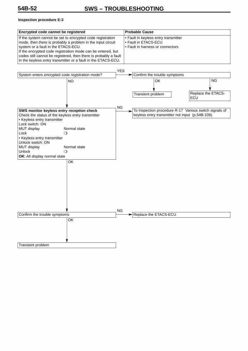
SWS – TROUBLESHOOTING54B-52
Inspection procedure E-3
System enters encrypted code registration mode?
SWS monitor keyless entry reception checkCheck the status of the keyless entry transmitter• Keyless entry transmitterLock switch: ONMUT display Normal stateLock
• Keyless entry transmitterUnlock switch: ONMUT display Normal stateUnlock
OK: All display normal state
Confirm the trouble symptoms
Transient problem
Confirm the trouble symptoms
Transient problem Replace the ETACS-ECU
To Inspection procedure R-17 Various switch signals ofkeyless entry transmitter not input (p.54B-109)
Replace the ETACS-ECU
Encrypted code cannot be registered Probable Cause
If the system cannot be set to encrypted code registrationmode, then there is probably a problem in the input circuitsystem or a fault in the ETACS-ECU.If the encrypted code registration mode can be entered, butcodes still cannot be registered, then there is probably a faultin the keyless entry transmitter or a fault in the ETACS-ECU.
• Fault in keyless entry transmitter• Fault in ETACS-ECU • Fault in harness or connectors
NO
NG
OK
OK
NG
YES
OK NG

SWS – TROUBLESHOOTING 54B-53
Keyless entry system working normally?
Confirm the trouble symptoms
Transient problem
To Inspection procedure E-1 Keyless entry system notworking at all (p.54B-50)
Use adjustment function to set the electric windowand sunroof operation in the multi-mode keyless entrysystem to “Operation switched on”.
To Inspection procedure A-3 No communication withETACS-ECU (p.54B-28)
To Inspection procedure A-5 No communication withelectric window main switch (electric window module)(p.54B-30)
To Inspection procedure R-17 Various switch signalsof keyless entry transmitter not input (p.54B-109)
Replace the ETACS-ECU
Replace the electric window main switch
Has electric window and sunroof operation in the multi-mode keyless entry system been set to “Operationswitched off” by the adjustment function?
SWS monitor ECU check• Ignition switch: OFF• Multi-mode operation performed using keyless entry
transmitter(1) ETACS-ECU(2) Electric window moduleOK: “OK” is displayed for all
SWS monitor keyless entry reception checkCheck the status of the keyless entry transmitter• Keyless entry transmitterLock switch: Long pressMUT display Normal stateLock
Lock long press
• Keyless entry transmitterUnlock switch: Long pressMUT display Normal stateUnlock
Unlock long press
OK: All display normal state
SWS monitor service data(Communications data) ETACS-ECU• Ignition switch: OFF• Multi-mode operation performed using keyless entry
transmitterItem No. Item Name Normal state34 Multi-mode keyless Multi-close or
multi-open ormulti-stop
OK: Displays normal state for each operation
Inspection procedure E-4
Multi-mode keyless entry function not working at all Probable CauseIf the electric windows, sunroof, and motorized door mirrorsare all working normally, then there is probably a fault in theETACS-ECU.It is also possible that the electric window and sunroofoperation has been set to “Operation switched off” by theadjustment function.
• Fault in ETACS-ECU • Fault in keyless entry transmitter• Fault in electric window main switch
YES
YES
OK
OK
OK
OK
NO
NG (1)
NG (2)
NG
NG
NG
NO

SWS – TROUBLESHOOTING54B-54
Inspection procedure E-5
Is the vehicle fitted with a sunroof?
Are electric windows working normally?
SWS monitor ECU check• Ignition switch: OFF• Multi-mode operation performed using keyless entrytransmitter(1) ETACS-ECU(2) Electric window moduleOK: “OK” is displayed for all
SWS monitor service data(Diagnosis by Function) Multi-mode keyless entry Multi-close• Ignition switch: OFF• Multi-mode operation performed using keyless entry
transmitterItem No. Item Name Normal state34 Multi-mode keyless Multi-close OK: Displays normal state for each operation
SWS monitor service data(Communications data) Door-to-door communications ∑ Ignition switch: OFF∑ Multi-mode operation performed using keyless entry
transmitterItem No. Item Name Normal stateC2 Front passenger AUTO ON *C62 Rear RH AUTO ON *CA Rear LH AUTO ON*OK: All display normal state
Transient problem
To Inspection procedure E-4 Keyless entry system notworking at all (p.54B-53)
To Inspection procedure D-1 None of electric windowsworking
To Inspection procedure A-3 No communication withETACS-ECU (p.54B-28)
To Inspection procedure A-5 No communication withelectric window main switch (electric window module)(p.54B-30)
Replace the ETACS-ECU
Replace the electric window main switch
Note: • When performing the SWS monitor ECU check, after operating the transmitter, the analysis for the electric window main
switch (electric window module) will display “¸” for approximately 1 minute, and then change to “¥”. However, the ETACS-ECU will only display “¸”.
• *: When a close operation is performed using the multi-mode keyless entry function, the display will change from “OFF” tothe normal state.
Electric windows not working correctly with multi-modekeyless entry function
Probable Cause
If the electric windows are working correctly in normaloperation, then there is probably a fault in the ETACS-ECU.
• Fault in ETACS-ECU • Fault in electric window main switch
YES
OK
OK
OK
NG
NG
YES
NO
NO
NG (1)
NG (2)

SWS – TROUBLESHOOTING 54B-55
Is the sunroof working correctly in normal operation?
SWS monitor ECU check• Ignition switch: OFF• Multi-mode operation performed using keyless entry
transmitter(1) ETACS-ECU(2) Sunroof ECUOK: “OK” is displayed for all
SWS monitor service data(Diagnosis by Function) Multi-mode keyless entry Multi-close• Ignition switch: OFF• Multi-mode operation performed using keyless entry
transmitterItem No. Item Name Normal state(a) 34 Multi-mode keyless Multi-close (b) 72 Sunroof ECU response Normal response*OK: All display normal state
Transient problem
To Inspection procedure F-1 Sunroof not working atall (p.54B-56)
To Inspection procedure A-3 No communication withETACS-ECU (p.54B-28)
To Inspection procedure A-6 No communication withsunroof motor assembly (p.54B-31)
Replace the ETACS-ECU
Replace the sunroof motor assembly
Inspection procedure E-6
Note:*: About 30 seconds after the end of the multi-mode operation, the display will change from “normal response” to “sleepresponse”.
Sunroof close operation not working correctly with multi-modekeyless entry function
Probable Cause
If the sunroof is working correctly in normal operation, thenthere is probably a fault in the ETACS-ECU.
• Fault in ETACS-ECU • Fault in sunroof motor assembly
YES
NO
NG (1)
NG (a)
NG (b)
NG (2)
OK
OK

SWS – TROUBLESHOOTING54B-56
Inspection Procedure F-1
Check connector D-27
Measure at the Sunroof motor assembly connector D-27• Detach the connector and measure at the harness side• Voltage between 1 & body earthOK: Battery voltage
Check the harness between the sunroof motor assemblyand the battery voltage, and repair
Measure at the Sunroof motor assembly connector D-27• Detach the connector and measure at the harness side• Ignition switch: ON• Voltage between 2 & body earthOK: Battery voltage
Measure at the Sunroof motor assembly connector D-27• Detach the connector and measure at the harness side• Connectivity between 5 & body earthOK: Connectivity
Measure at the Sunroof switch connector D-26• Detach the connector and measure at the harness side• Connectivity between 4 & body earthOK: Connectivity
Check connector D-26
Check the sunroof switch (See Chap. 42) *
Confirm the trouble symptoms
Transient problem
Check connectors C-113, C-223, C-210, C-32
Check connectors C-216, C-210
Check the harness between the sunroof motor assemblyand the ignition switch (IG2), and repair
Check the harness between the sunroof motor assemblyand the body earth, and repair
Check the harness between the sunroof switch and thebody earth, and repair
Replace the sunroof motor assembly
Sunroof not working at all Probable Cause
There is probably a fault in the sunroof switch, a problem inthe sunroof motor assembly power circuit, or a fault in thesunroof motor assembly.
• Fault in sunroof switch• Fault in sunroof motor assembly• Fault in harness or connectors
Note:*: See ’00-5 Lancer Cedia Servicing Manual (No. 1036K00)
OK
OK NG
NG
Repair
Repair
OK
NG
NG
NGRepair
OK
OK
OK
OK
OK
OK
OK
NG
NG
NG
NG
NG
Repair
Repair
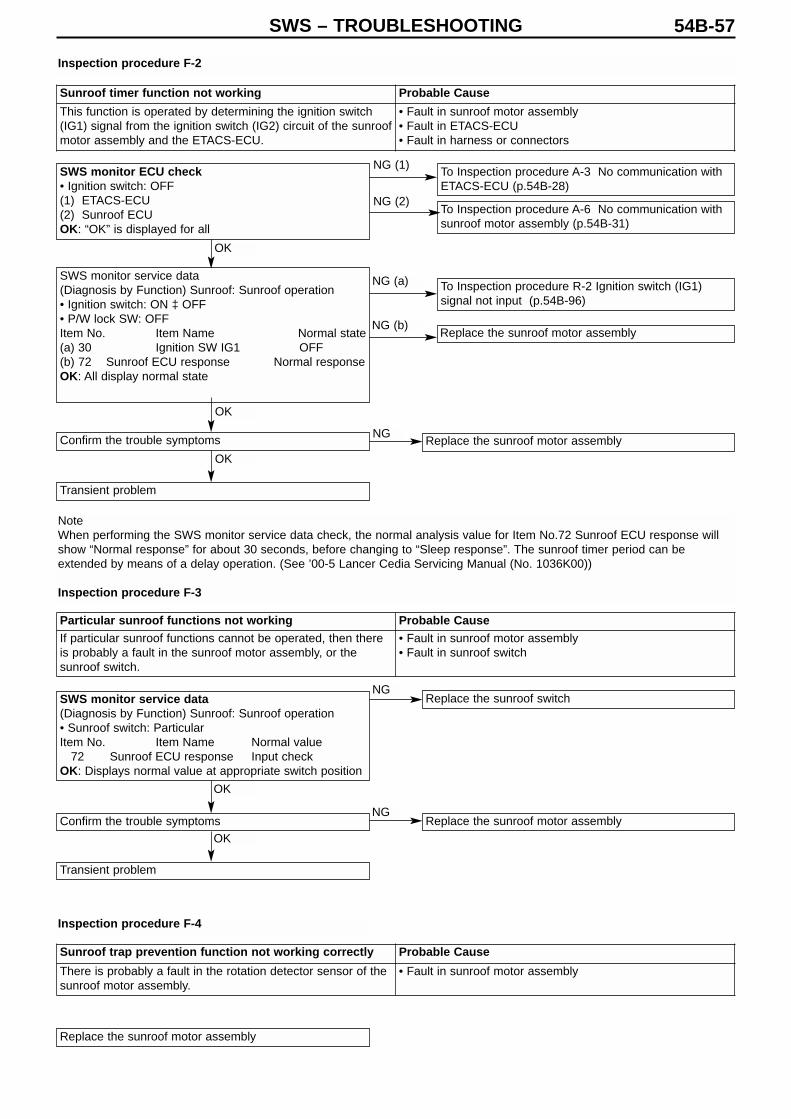
SWS – TROUBLESHOOTING 54B-57
SWS monitor ECU check• Ignition switch: OFF(1) ETACS-ECU(2) Sunroof ECUOK: “OK” is displayed for all
SWS monitor service data(Diagnosis by Function) Sunroof: Sunroof operation• Ignition switch: ON ‡ OFF• P/W lock SW: OFFItem No. Item Name Normal state(a) 30 Ignition SW IG1 OFF(b) 72 Sunroof ECU response Normal responseOK: All display normal state
SWS monitor service data(Diagnosis by Function) Sunroof: Sunroof operation• Sunroof switch: Particular Item No. Item Name Normal value
72 Sunroof ECU response Input checkOK: Displays normal value at appropriate switch position
Confirm the trouble symptoms
Transient problem
Confirm the trouble symptoms
Transient problem
Replace the sunroof motor assembly
Replace the sunroof switch
Replace the sunroof motor assembly
To Inspection procedure A-3 No communication withETACS-ECU (p.54B-28)
To Inspection procedure A-6 No communication withsunroof motor assembly (p.54B-31)
To Inspection procedure R-2 Ignition switch (IG1)signal not input (p.54B-96)
Replace the sunroof motor assembly
Replace the sunroof motor assembly
Inspection procedure F-2
Note When performing the SWS monitor service data check, the normal analysis value for Item No.72 Sunroof ECU response willshow “Normal response” for about 30 seconds, before changing to “Sleep response”. The sunroof timer period can beextended by means of a delay operation. (See ’00-5 Lancer Cedia Servicing Manual (No. 1036K00))
Inspection procedure F-3
Sunroof timer function not working Probable Cause
This function is operated by determining the ignition switch(IG1) signal from the ignition switch (IG2) circuit of the sunroofmotor assembly and the ETACS-ECU.
• Fault in sunroof motor assembly• Fault in ETACS-ECU • Fault in harness or connectors
Particular sunroof functions not working Probable CauseIf particular sunroof functions cannot be operated, then thereis probably a fault in the sunroof motor assembly, or thesunroof switch.
• Fault in sunroof motor assembly• Fault in sunroof switch
Sunroof trap prevention function not working correctly Probable Cause
There is probably a fault in the rotation detector sensor of thesunroof motor assembly.
• Fault in sunroof motor assembly
Inspection procedure F-4
OK
OK
OK
OK
OK
NG
NG
NG
NG (b)
NG (a)
NG (1)
NG (2)

SWS – TROUBLESHOOTING54B-58
Inspection procedure G-1
SWS monitor ECU check• Ignition switch: OFF(1) Column switch(2) Front ECUOK: “OK” is displayed for all
SWS monitor service data(Diagnosis by Function) Windscreen wipers: INT• Ignition switch: ACC• Windscreen wiper switch: INTItem No. Item Name Normal value (a) 05 INT wiper SW ON(b) 70 Front ECU response Normal response or
high beam responseOK: All display normal value
Check connector A-13X
Measure at Front ECU connector A-13X• Detach the connector and measure at the relay box
side• Ignition switch: ACC• Voltage between 24 & body earthOK: Battery voltage
Check connector B-12
Check the windscreen wiper motor (See Chap. 51*)
Measure at Windscreen wiper motor connector B-12• Detach the connector and measure at the harness side• Connectivity between 5 & body earthOK: Connectivity
Check connector C-34
Confirm the trouble symptoms
Transient problem
To Inspection procedure A-2 No communication withcolumn switch (column ECU) (p.54B-27)
To Inspection procedure A-4 No communication withfront ECU (p.54B-29)
Replace the column ECU
Replace the front ECU
Check connectors C-21, C-209, C-210
Check the harness between the front ECU and theignition switch (ACC)
Check the harness between windscreen wiper motorand the body earth
Replace the front ECU
Note:*: See ’00-5 Lancer Cedia Servicing Manual (No. 1036K00)
Windscreen wipers not working at all Probable CauseThere is probably a fault in the windscreen wipers, a fault inthe column ECU or a fault in the front ECU.If the SWS monitor ECU check returns an NG result, then thewiper backup circuit should also be checked, and repaired, ifnecessary.
• Fault in column switch• Fault in front ECU• Fault in harness or connectors
OK
NG (1)
NG (a)
NG (b)
NG (2)
OK
OK
Repair
Repair
Repair
Repair
Replace
NG
NG
NG
NG
NG
NG
NG
NG
OK
OK
OK
OK
OK
OK
OK
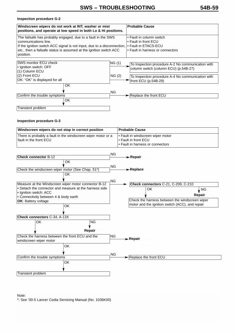
SWS – TROUBLESHOOTING 54B-59
SWS monitor ECU check• Ignition switch: OFF(1) Column ECU(2) Front ECUOK: “OK” is displayed for all
To Inspection procedure A-2 No communication withcolumn switch (column ECU) (p.54B-27)
Confirm the trouble symptoms
Transient problem
Check connector B-12
Check the windscreen wiper motor (See Chap. 51*)
Check connectors C-34, A-13X
Check the harness between the front ECU and thewindscreen wiper motor
Confirm the trouble symptoms
Transient problem
Check connectors C-21, C-209, C-210
Check the harness between the windscreen wipermotor and the ignition switch (ACC), and repair
Replace the front ECU
Measure at the Windscreen wiper motor connector B-12• Detach the connector and measure at the harness side• Ignition switch: ACC• Connectivity between 4 & body earth OK: Battery voltage
Replace the front ECU
To Inspection procedure A-4 No communication withfront ECU (p.54B-29)
Inspection procedure G-2
Inspection procedure G-3
Note:*: See ’00-5 Lancer Cedia Servicing Manual (No. 1036K00)
Windscreen wipers do not work at INT, washer or mistpositions, and operate at low speed in both Lo & Hi positions.
Probable Cause
The failsafe has probably engaged, due to a fault in the SWScommunications line.If the ignition switch ACC signal is not input, due to a disconnection,etc., then a failsafe status is assumed at the ignition switch ACCposition.
• Fault in column switch• Fault in front ECU• Fault in ETACS-ECU • Fault in harness or connectors
Windscreen wipers do not stop in correct position Probable Cause
There is probably a fault in the windscreen wiper motor or afault in the front ECU
• Fault in windscreen wiper motor• Fault in front ECU• Fault in harness or connectors
OK
OK
OK
OK
OK
OK
OK
OK
OK
NG (1)
NG
NG
NG
NG
NG
NG
NG
NG
Repair
Repair
Repair
Repair
Replace
NG (2)

SWS – TROUBLESHOOTING54B-60
Inspection procedure G-4
SWS monitor service data(Communications data) Column switch (column ECU)• All wiper switches: ONItem No. Item Name Normal value05 INT wiper SW ON06 LO wiper SW ON07 HI wiper SW ON08 Mist wiper SW ON
OK: Display normal value at respective switch positions
Check connector B-12
Are the high speed and mist wipers working?
Measure at Windscreen wiper motor connector B-12• Detach the connector and measure at the harness side• Windscreen wiper switch: LO• Connectivity between 1 & body earthOK: Battery voltage
Check connectors A-13X, C-34
Check the harness between the windscreen wiper motor(LO) and the front ECU
Confirm the trouble symptoms
Transient problem
Replace the column ECU
To next page
Confirm the trouble symptoms
Replace the front ECU
Transient problem Replace the windscreenwiper motor
Windscreen wipers cannot be operated normally Probable Cause
There is probably a fault in the windscreen wiper motor, a faultin the column ECU, or a fault in the front ECU
• Fault in column switch• Fault in windscreen wiper motor• Fault in front ECU• Fault in harness or connectors
NG
OK
NO
NG
OK
NG
NG
OK NG
NG
OK
OK
OK
NG
Repair
Repair
Repair
YES
OK

SWS – TROUBLESHOOTING 54B-61
From previous page
Check connectors A-13X, C-34, B-12
Check the harness between the windscreen wiper motor(HI) and the front ECU
Confirm the trouble symptoms
Transient problem
Confirm the trouble symptoms
Transient problem
Check connectors C-203
Measure at the Column ECU connector C-203• Detach the connector and measure at the harness side• Resistance between 4 and 6OK: Changes from 0 → 1 kΩ
Replace the column ECU
Check connector C-225
Check the harness between column switch (intermittentvolume) and the ETACS-ECU
Confirm the trouble symptoms
Replace the ETACS-ECU
Transient problem
Replace the front ECU
Confirm the trouble symptoms
Replace the front ECU
Transient problem Replace the windscreenwiper motor
Measure at Windscreen wiper motor connector B-12• Detach the connector and measure at the harness side• Windscreen wiper switch: HI• Voltage between 2 & body earthOK: Battery voltage
SWS monitor service data(Diagnosis by Function) Windscreen wiper : INT• Vehicle speed: 0 km/h• Ignition switch: ACCItem No. Item Name Normal value37 Wiper INT period 2.4 – 18.0 s
OK: Normal value display changes with change involume of intermittent wiper volume
Intermittent time interval of windscreen wipers does notchange with vehicle speed or operation of intermittentwindscreen wiper volume
Probable Cause
There is probably a fault in the front ECU or the ETACS-ECU. • Fault in front ECU• Fault in ETACS-ECU • Fault in harness or connectors
Inspection procedure G-5
NG
NG
NG
NG
NG NG
NG
NG
NG
NG
OK
Repair
Repair
Repair
Repair
Repair
OK
OK
OK
OK
OK
OK
OK
OK
OK
NG
OK
OK NG
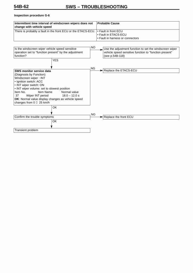
SWS – TROUBLESHOOTING54B-62
Inspection procedure G-6
Is the windscreen wiper vehicle speed sensitiveoperation set to “function present” by the adjustmentfunction?
SWS monitor service data(Diagnosis by Function) Windscreen wiper : INT• Ignition switch: ACC• INT wiper switch: ON• INT wiper volume: set to slowest positionItem No. Item Name Normal value37 Wiper INT period 18.0 – 12.0 s
OK: Normal value display changes as vehicle speedchanges from 0 → 25 km/h
Confirm the trouble symptoms
Transient problem
Use the adjustment function to set the windscreen wipervehicle speed sensitive function to “function present”(see p.54B-118)
Replace the ETACS-ECU
Replace the front ECU
Intermittent time interval of windscreen wipers does notchange with vehicle speed
Probable Cause
There is probably a fault in the front ECU or the ETACS-ECU. • Fault in front ECU• Fault in ETACS-ECU • Fault in harness or connectors
YES
NO
NG
NG
OK
OK

SWS – TROUBLESHOOTING 54B-63
Are the windscreen wipers working correctly?
Check connector F-19
Check the windscreen washer motor (See Chap. 51*)
Check connectors A-13X, C-31, C-116
Check the harness between the windscreen washermotor and the front ECU
Confirm the trouble symptoms
Transient problem
To Inspection procedure G-1 Windscreen wipers notworking at all (see p.54B-58)
To Inspection procedure A-2 No communication withcolumn switch (column ECU) (p.54B-27)
To Inspection procedure A-4 No communication withfront ECU (p.54B-29)
Replace the column switch
Replace the front ECU
Check the harness between the windscreen washermotor and the body earth
Replace the front ECU
Measure at Windscreen washer motor connector F-19• Detach the connector and measure on the harness side• Connectivity between 1 & body earthOK: Connectivity
SWS monitor ECU check• Ignition switch: OFF(1) Column ECU(2) Front ECUOK: “OK” is displayed for all
SWS monitor service data(Diagnosis by Function)Windscreen wiper: Washer• Windscreen washer switch: ON• Ignition switch: ACCItem No. Item Name Normal value(a) 09 Front washer SW ON(b) 70 Front ECU response Normal response
or high beam responseOK: Normal values displayed for all
Inspection procedure G-7
Note*: See ’01-1 Lancer Evolution VII Servicing Manual (No. 1036K02)
Windscreen washer not working correctly Probable CauseThere is probably a fault in the windscreen washer motor, afault in the column ECU, or a fault in the front ECU
• Fault in column switch• Fault in front ECU• Fault in windscreen washer motor• Fault in harness or connectors
YES
OK
OK
NG
NG
NG
OK
OK
OK
OK
OK
OK
NG
NG
NG
NO
NG (1)
NG (2)
NG (b)
Repair
RepairRepair
Replace
NG (a)

SWS – TROUBLESHOOTING54B-64
Inspection procedure H-1
SWS monitor ECU check• Ignition switch: OFF(1) ETACS-CU(2) Column ECUOK: “OK” is displayed for all
SWS monitor service data(Diagnosis by Function)Rear wiper / washer: Rear wiper• Ignition switch: ACC• Rear wiper switch: ONItem No. Item Name Normal value(a) 31 Ignition SW ACC ON(b) 13 Rear wiper SW ONOK: Normal values displayed for all
Check connector F-05
Check rear wiper motor (See Chap. 51*)
Measure at Rear wiper motor connector F-05• Detach the connector and measure at the harness side• Connectivity between 1 & body earthOK: Connectivity
Check connectors C-224, C-215
Check the harness between the rear wiper motor and theETACS-ECU
Confirm the trouble symptoms
Transient problem
To Inspection procedure A-3 No communication withETACS-ECU (p.54B-28)
To Inspection procedure A-2 No communication withcolumn switch (column ECU) (p.54B-27)
To Inspection procedure R-1 “Ignition switch (ACC)signal not input” (p.54B-96)
Replace the column switch
Check the harness between the rear wiper motor andthe body earth, and repair
Replace the ETACS-ECU
Note:*: See ’00-5 Lancer Sedia Servicing Manual (No. 1036K00)
Rear wiper not working at all Probable Cause
The rear wiper is operated by determining the following inputsignals in the ETACS-ECU.• Ignition switch (ACC)• Rear wiper switchIf the rear wiper does not work, then there is probably amalfunction in the input circuit system for these signals, or afault in the rear wiper motor, or a fault in the ETACS-ECU.
• Fault in rear wiper motor• Fault in column switch• Fault in ETACS-ECU • Fault in harness or connectors
OK
OK
NG
NG
NG
NG
NG
NG
Replace
Repair
Repair
Repair
OK
OK
OK
OK
OK
OK
NG (1)
NG (2)
NG (a)
NG (b)
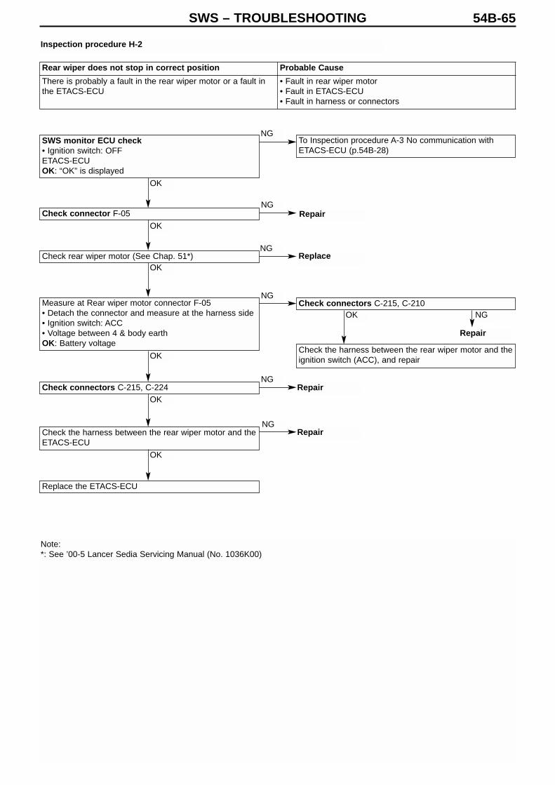
SWS – TROUBLESHOOTING 54B-65
SWS monitor ECU check• Ignition switch: OFFETACS-ECUOK: “OK” is displayed
Check connector F-05
Check rear wiper motor (See Chap. 51*)
Check connectors C-215, C-224
Check the harness between the rear wiper motor and theETACS-ECU
Replace the ETACS-ECU
To Inspection procedure A-3 No communication withETACS-ECU (p.54B-28)
Check connectors C-215, C-210
Check the harness between the rear wiper motor and theignition switch (ACC), and repair
Measure at Rear wiper motor connector F-05• Detach the connector and measure at the harness side• Ignition switch: ACC• Voltage between 4 & body earthOK: Battery voltage
Inspection procedure H-2
Note:*: See ’00-5 Lancer Sedia Servicing Manual (No. 1036K00)
Rear wiper does not stop in correct position Probable Cause
There is probably a fault in the rear wiper motor or a fault inthe ETACS-ECU
• Fault in rear wiper motor• Fault in ETACS-ECU • Fault in harness or connectors
Replace
Repair
Repair
Repair
Repair
NG
NG
NG
NG
NG
NG
NG
OK
OK
OK
OK
OK
OK
OK

SWS – TROUBLESHOOTING54B-66
Inspection procedure H-3
SWS monitor ECU check• Ignition switch: OFFETACS-ECUOK: “OK” is displayed
SWS monitor service data(Diagnosis by Function)Rear wiper / washer: Reverse continuous operation• Ignition switch: ON• Rear wiper switch: ON• Shift position: RItem No. Item Name Normal value
41 Inhibitor SW (R) ONOK: Normal values displayed
Confirm the trouble symptoms
Transient problem
To Inspection procedure A-3 No communication withETACS-ECU (p.54B-28)
To Inspection procedure R-3 “Reversing light switchsignal not input” (p.54B-97)
Replace the ETACS-ECU
Rear wiper does not operate continuously, even whenshift is set to R position
Probable Cause
There is probably a malfunction in the reversing light switchinput circuit system, or a fault in the ETACS-ECU.
• Fault in reverse light switch• Fault in ETACS-ECU • Fault in harness or connectors
OK
OK
NG
NG
NG
NG

SWS – TROUBLESHOOTING 54B-67
Is the rear wiper working normally?
SWS monitor ECU check• Ignition switch: OFFETACS-ECUOK: “OK” is displayed
SWS monitor service data(Diagnosis by Function)Rear wiper / washer: Rear wiper• Ignition switch: ACC• Rear washer switch: ONItem No. Item Name Normal value
14 Rear washer SW ONOK: Normal value displayed
Check connector F-20
Check rear washer motor (See Chap. 51*)
Measure at Rear washer motor connector F-20• Detach the connector and measure at the harness side• Connectivity between 1 & body earthOK: Battery voltage
Check connector C-226, C-116
Check the harness between the rear washer motor andthe ETACS-ECU
Confirm the trouble symptoms
Transient problem
To Inspection procedure H-1 Rear wiper not working atall (p.54B-64)
To Inspection procedure A-3 No communication withETACS-ECU (p.54B-28)
To Inspection procedure R-6 Rear washer switch signalnot input (p.54B-100)
Check the harness between rear washer motor and thebody earth, and repair
Replace the ETACS-ECU
Inspection procedure H-4
Note*: See ’01-1 Lancer Evolution VII Servicing Manual (No. 1036K02)
Rear washer does not work Probable Cause
There is probably an abnormality in the rear washer switchinput circuit system, a fault in the rear washer motor, or a faultin the ETACS-ECU.
• Fault in rear washer motor• Fault in column switch• Fault in ETACS-ECU • Fault in harness or connectors
Replace
Repair
Repair
Repair
YES
NO
OK
OK
OK
OK
OK
OK
OK
OK
NO
NG
NG
NG
NG
NG
NG
NG
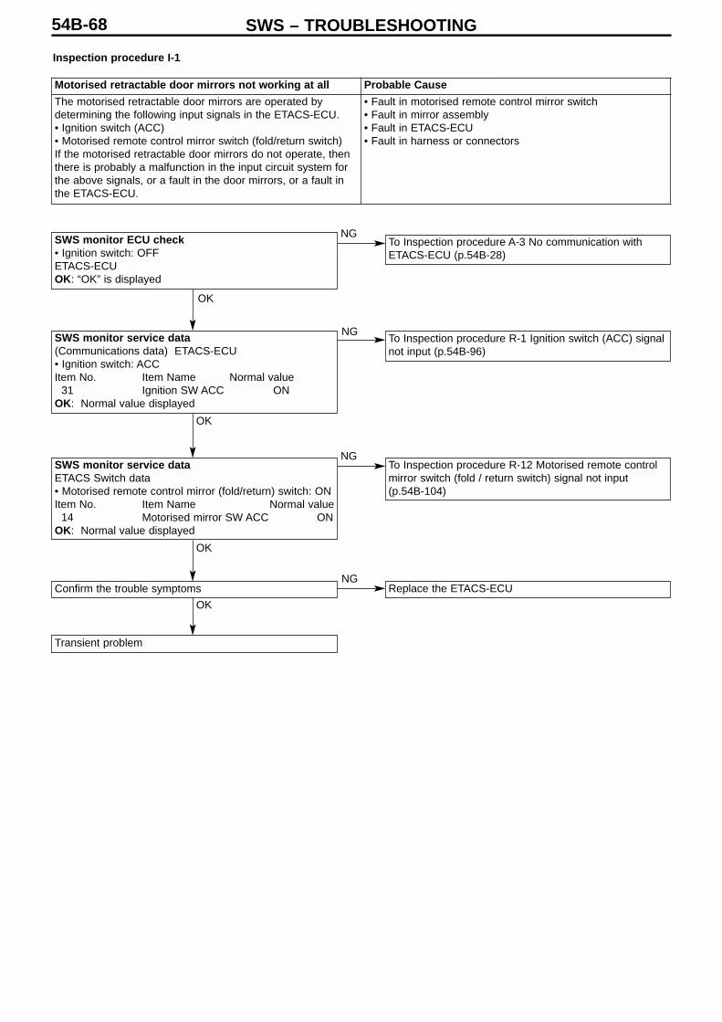
SWS – TROUBLESHOOTING54B-68
Inspection procedure I-1
SWS monitor ECU check• Ignition switch: OFFETACS-ECUOK: “OK” is displayed
SWS monitor service data(Communications data) ETACS-ECU • Ignition switch: ACCItem No. Item Name Normal value
31 Ignition SW ACC ONOK: Normal value displayed
SWS monitor service dataETACS Switch data• Motorised remote control mirror (fold/return) switch: ONItem No. Item Name Normal value
14 Motorised mirror SW ACC ONOK: Normal value displayed
Confirm the trouble symptoms
Transient problem
To Inspection procedure A-3 No communication withETACS-ECU (p.54B-28)
To Inspection procedure R-1 Ignition switch (ACC) signalnot input (p.54B-96)
To Inspection procedure R-12 Motorised remote controlmirror switch (fold / return switch) signal not input(p.54B-104)
Replace the ETACS-ECU
Motorised retractable door mirrors not working at all Probable Cause
The motorised retractable door mirrors are operated bydetermining the following input signals in the ETACS-ECU. • Ignition switch (ACC)• Motorised remote control mirror switch (fold/return switch)If the motorised retractable door mirrors do not operate, thenthere is probably a malfunction in the input circuit system forthe above signals, or a fault in the door mirrors, or a fault inthe ETACS-ECU.
• Fault in motorised remote control mirror switch• Fault in mirror assembly• Fault in ETACS-ECU • Fault in harness or connectors
OK
OK
OK
OK
NG
NG
NG
NG
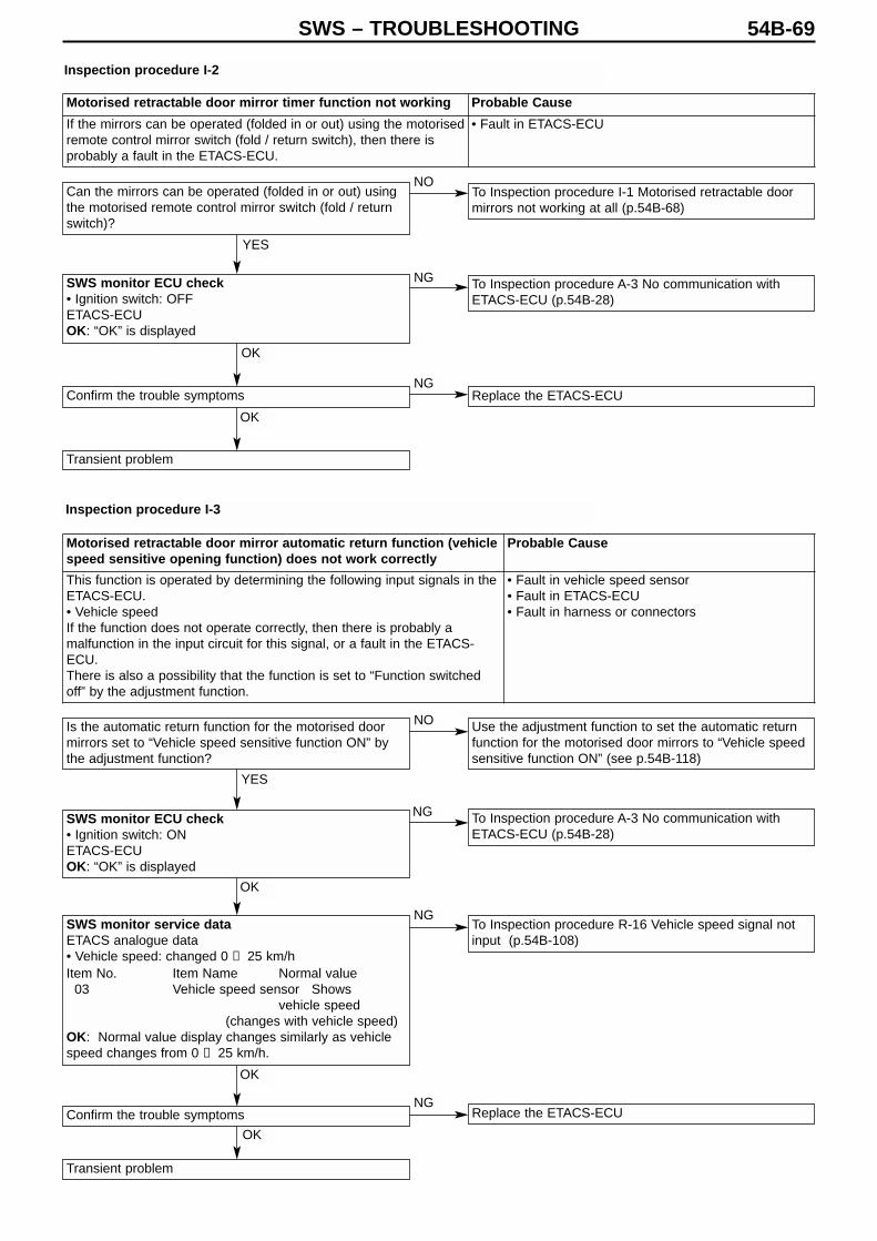
SWS – TROUBLESHOOTING 54B-69
Can the mirrors can be operated (folded in or out) usingthe motorised remote control mirror switch (fold / returnswitch)?
SWS monitor ECU check• Ignition switch: OFFETACS-ECUOK: “OK” is displayed
Confirm the trouble symptoms
Transient problem
Is the automatic return function for the motorised doormirrors set to “Vehicle speed sensitive function ON” bythe adjustment function?
SWS monitor ECU check• Ignition switch: ONETACS-ECUOK: “OK” is displayed
SWS monitor service dataETACS analogue data• Vehicle speed: changed 0 → 25 km/hItem No. Item Name Normal value
03 Vehicle speed sensor Showsvehicle speed
(changes with vehicle speed)OK: Normal value display changes similarly as vehiclespeed changes from 0 → 25 km/h.
Confirm the trouble symptoms
Transient problem
Use the adjustment function to set the automatic returnfunction for the motorised door mirrors to “Vehicle speedsensitive function ON” (see p.54B-118)
To Inspection procedure A-3 No communication withETACS-ECU (p.54B-28)
To Inspection procedure R-16 Vehicle speed signal notinput (p.54B-108)
Replace the ETACS-ECU
To Inspection procedure I-1 Motorised retractable doormirrors not working at all (p.54B-68)
To Inspection procedure A-3 No communication withETACS-ECU (p.54B-28)
Replace the ETACS-ECU
Inspection procedure I-2
Inspection procedure I-3
Motorised retractable door mirror timer function not working Probable Cause
If the mirrors can be operated (folded in or out) using the motorisedremote control mirror switch (fold / return switch), then there isprobably a fault in the ETACS-ECU.
• Fault in ETACS-ECU
Motorised retractable door mirror automatic return function (vehiclespeed sensitive opening function) does not work correctly
Probable Cause
This function is operated by determining the following input signals in theETACS-ECU. • Vehicle speedIf the function does not operate correctly, then there is probably amalfunction in the input circuit for this signal, or a fault in the ETACS-ECU.There is also a possibility that the function is set to “Function switchedoff” by the adjustment function.
• Fault in vehicle speed sensor• Fault in ETACS-ECU • Fault in harness or connectors
YES
OK
OK
NO
NG
NG
NO
YES
OK
OK
OK
NG
NG
NG
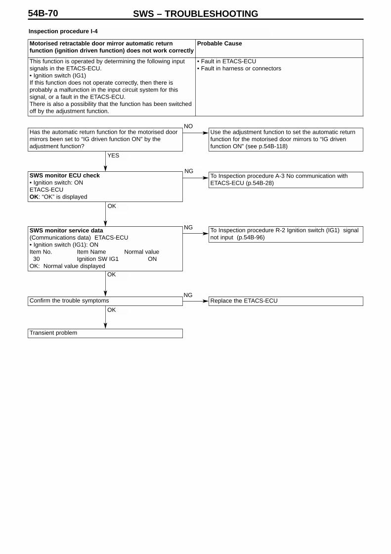
SWS – TROUBLESHOOTING54B-70
Inspection procedure I-4
Has the automatic return function for the motorised doormirrors been set to “IG driven function ON” by theadjustment function?
SWS monitor ECU check• Ignition switch: ONETACS-ECUOK: “OK” is displayed
SWS monitor service data(Communications data) ETACS-ECU • Ignition switch (IG1): ONItem No. Item Name Normal value
30 Ignition SW IG1 ONOK: Normal value displayed
Confirm the trouble symptoms
Transient problem
Use the adjustment function to set the automatic returnfunction for the motorised door mirrors to “IG drivenfunction ON” (see p.54B-118)
To Inspection procedure A-3 No communication withETACS-ECU (p.54B-28)
To Inspection procedure R-2 Ignition switch (IG1) signalnot input (p.54B-96)
Replace the ETACS-ECU
Motorised retractable door mirror automatic returnfunction (ignition driven function) does not work correctly
Probable Cause
This function is operated by determining the following inputsignals in the ETACS-ECU. • Ignition switch (IG1)If this function does not operate correctly, then there isprobably a malfunction in the input circuit system for thissignal, or a fault in the ETACS-ECU.There is also a possibility that the function has been switchedoff by the adjustment function.
• Fault in ETACS-ECU • Fault in harness or connectors
YES
OK
OK
OK
NO
NG
NG
NG

SWS – TROUBLESHOOTING 54B-71
Has the automatic return function for the motorised doormirrors been set to “Keyless driven function ON” by theadjustment function?
SWS monitor ECU check• Ignition switch: ONETACS-ECUOK: “OK” is displayed
SWS monitor keyless entry reception checkCheck using all keyless entry transmitters with whichproblems were confirmed• Keyless entry transmitterLock switch: ONMUT display Normal stateLock • Keyless entry transmitterUnlock switch: Long pressMUT display Normal stateUnlock OK: All display normal state
Confirm the trouble symptoms
Transient problem
Use the adjustment function to set the automatic returnfunction for the motorised door mirrors to “Keyless drivenfunction ON” (see p.54B-118)
To Inspection procedure A-3 No communication withETACS-ECU (p.54B-28)
To Inspection procedure R-17 Various switch signals ofkeyless entry transmitter not input (p.54B-109)
Replace the ETACS-ECU
Inspection procedure I-5
Motorised retractable door mirror automatic returnfunction (keyless driven function) does not work correctly
Probable Cause
This function is operated by determining the following inputsignals in the ETACS-ECU. • Keyless entry transmitterIf this function does not operate correctly, then there isprobably a malfunction in the input circuit system for thissignal, or a fault in the ETACS-ECU.There is also a possibility that the function has been switchedoff by the adjustment function.
• Fault in keyless entry transmitter• Fault in ETACS-ECU • Fault in harness or connectors
YES
OK
OK
OK
NO
NG
NG
NG

SWS – TROUBLESHOOTING54B-72
Inspection procedure I-6
Check connector(Driver’s side) E-01(Front passenger’s) E-07
Check the mirror assembly (motorised stowing operation)of the door that is not working (See Chap. 51*)
Check connectors(Driver’s side) C-226, C-114(Front passenger’s) C-226, C-33
Check the harness between the door mirror and theETACS-ECU
Confirm the trouble symptoms
Transient problem
Replace the ETACS-ECU
Note:*: See ’00-5 Lancer Sedia Servicing Manual (No. 1036K00)
One of the motorised retractable door mirrors is not working. Probable Cause
The motorised retractable door mirrors are operated bydetermining the following input signals in the ETACS-ECU. • Ignition switch (ACC)If any of the motorised door mirrors is not working, then there isprobably a malfunction in the input circuit system for this signal, afault in the door mirror, or a fault in the ETACS-ECU.
• Fault in mirror assembly• Fault in ETACS-ECU • Fault in harness or connectors
Replace
Repair
Repair
Repair
NG
NG
NG
NG
NG
OK
OK
OK
OK
OK

SWS – TROUBLESHOOTING 54B-73
Inspection procedure J-1
Ignition key cylinder illumination light does not light upand switch off correctly
Probable Cause
(Vehicle not fitted with keyless entry)The ignition key cylinder illumination light is switched on bydetermining the following input signals in the ETACS-ECU.• Ignition switch (IG1)• Key reminder switch• Driver’s door switchIf it does not work correctly, then there is probably amalfunction in the input circuit system for these signals, a faultin the ignition key cylinder illumination light, or a fault in theETACS-ECU.
• Fault in key reminder switch• Fault in driver’s door switch• Fault in ignition key cylinder illumination light• Fault in ETACS-ECU • Fault in harness or connectors
(Vehicle fitted with keyless entry)The ignition key cylinder illumination light is switched on bydetermining the following input signals in the ETACS-ECU.In addition, since the interior lights are switched off by theinterior light cut-off function, then the input signal for theinterior light cut off should also be checked at the same time.• Ignition switch (ACC)• Ignition switch (IG1)• Key reminder switch• Driver’s door switch• All door switch• Generic fuse No.17If it does not work correctly, then there is probably amalfunction in the input circuit systems for these signals, afault in the ignition key cylinder illumination light, a malfunctionin the interior light cut-off, or a fault in the ETACS-ECU.
• Fault in key reminder switch• Fault in driver’s door switch• Fault in ignition key cylinder illumination light• Fault in ETACS-ECU • Fault in harness or connectors

SWS – TROUBLESHOOTING54B-74
(Vehicle not fitted with keyless entry)
SWS monitor ECU check• Ignition switch: OFFETACS-ECUOK: “OK” is displayed
SWS monitor service data(Communications data) ETACS-ECU • Ignition switch: ON• Driver’s door: OpenItem No. Item Name Normal value(a) 30 Ignition SW IG1 ON(b) 32 Driver’s door SW RH ONOK: Normal value displayed for all
SWS monitor service dataETACS switch data• Ignition switch: OFF (key inserted)Item No. Item Name Normal value03 Key reminder SW OFFOK: Normal value displayed for all
Check connector C-202
Check at Ignition key cylinder illumination light connectorC-202• Detach the connector and check at the harness side• Voltage between 2 & body earthOK: Battery voltage
Check the ignition key cylinder illumination light bulb
Check connector C-225
Check the harness between the ETACS-ECU and theignition key cylinder illumination light
Confirm the trouble symptoms
Transient problem
To Inspection procedure A-3 No communication withETACS-ECU (p.54B-28)
To Inspection procedure R-2 Ignition switch (IG1)signal not input (p.54B-96)
To Inspection procedure R-4 Driver’s door switch signalnot input (p.54B-98)
To Inspection procedure R-11 Key reminder switchsignal not input (p.54B-103)
Check connectors C-32, C-110, C-211, C-224, C-225
Check the harness between the ETACS-ECU and thefusible link (1)
Confirm the trouble symptoms
Transient problem Replace the ETACS-ECU
Replace the ETACS-ECU
Replace
Repair
Repair
Repair
Repair
Repair
OK
OK
NG (b)
OK
OK
OK
OK
OK
OK
NG
NG
NG
NG
NG
NG
NG
OK
OK
OK
OK
NG
NG
NG
NG
NG (a)

SWS – TROUBLESHOOTING 54B-75
Does the interior light switch on normally?
SWS monitor ECU check• Ignition switch: OFFETACS-ECUOK: “OK” is displayed
SWS monitor service data(Communications data) ETACS-ECU • Ignition switch: ON• Driver’s door: OpenItem No. Item Name Normal value(a) 30 Ignition SW IG1 ON(b) 32 Driver’s door SW RH ONOK: Normal value displayed for all
SWS monitor service dataETACS switch data• Ignition switch: OFF (key inserted)Item No. Item Name Normal value
03 Key reminder SW OFFOK: Normal value displayed for all
Check connector C-202
Check the ignition key cylinder illumination light bulb
Check connector C-225
Check the harness between the ETACS-ECU and theignition key cylinder illumination light
Confirm the trouble symptoms
Transient problem
To Inspection procedure N-1 Interior light does not lightup or switch off correctly (p.54B-76)
To Inspection procedure A-3 No communication withETACS-ECU (p.54B-28)
To Inspection procedure R-2 Ignition switch (IG1)signal not input (p.54B-96)
To Inspection procedure R-4 Driver’s door switch signalnot input (p.54B-98)
To Inspection procedure R-11 Key reminder switchsignal not input (p.54B-103)
Replace the ETACS-ECU
(Vehicle fitted with keyless entry)
Replace
Repair
Repair
YES
NO
NG
NG (a)
NG (b)
OK
OK
OK
OK
OK
OK
OK
OK
NG
NG
NG
NG
NG

SWS – TROUBLESHOOTING54B-76
Inspection procedure K-1
SWS monitor ECU check• Ignition switch: OFF(1) ETACS-ECU(2) Column ECU(3) Front ECUOK: “OK” is displayed for all
SWS monitor ECU check• Ignition switch: OFF(1) Column ECU(2) Front ECUOK: “OK” is displayed for all
SWS monitor service data(Function by Diagnosis) Lighting: Tail• Ignition switch: ON• Tail light switch: ONItem No. Item Name Normal value(a) 01 Tail light SW ON(b) 35 HD light auto cut-off OFF(c) 70 Front ECU response Normal
responseOK: Normal value displayed for all
Confirm the trouble symptoms
Transient problem
To Inspection procedure A-2 No communication withcolumn switch (column ECU) (p.54B-27)
To Inspection procedure A-4 No communication withfront ECU (p.54B-29)
To Inspection procedure R-5 Tail light switch signal notinput (p.54B-99)
To Inspection procedure K-6 Headlight automatic cut-off function not working correctly (p.54B-80)
Replace the front ECU
Replace the front ECU
Transient problem
To Inspection procedure A-3 No communication withETACS-ECU (p.54B-28)
To Inspection procedure A-2 No communication withcolumn switch (column ECU) (p.54B-27)
To Inspection procedure A-4 No communication with frontECU (p.54B-29)
Inspection procedure K-2
Head lights do not light up when passing switch is on. Low beamlights up (cannot be changed using dimmer switch)
Probable Cause
If the low beam turns on, regardless of the position of the headlightswitch, then the headlight failsafe function has probably engaged.
• Fault in column switch • Fault in front ECU• Fault in ETACS-ECU • Fault in harness or connectors
Tail lights do not light up correctly Probable CauseIf all of the tail lights do not light up properly, then there isprobably a malfunction in the tail light switch input circuitsystem or a fault in the front ECU.
• Fault in column switch • Fault in front ECU• Fault in harness or connectors
NG (1)
NG (3)
NG (2)
OK
OK
OK
OK
NG
NG (c)
NG (b)
NG (a)
NG (2)
NG (1)

SWS – TROUBLESHOOTING 54B-77
SWS monitor ECU check• Ignition switch: OFF(1) Column ECU(2) Front ECUOK: “OK” is displayed for all
SWS monitor service data(Function by Diagnosis) Lighting: LO• Ignition switch: ON• Head light switch: ONItem No. Item Name Normal value(a) 01 Tail light SW ON(b) 35 HD light auto cut-off OFF(c) 70 Front ECU response Normal responseOK: Normal value displayed for all
Confirm the trouble symptoms
Transient problem
To Inspection procedure A-2 No communication withcolumn switch (column ECU) (p.54B-27)
To Inspection procedure A-4 No communication withfront ECU (p.54B-29)
To Inspection procedure R-5 Head light switch signalnot input (p.54B-99)
To Inspection procedure R-2 Ignition switch (IG1)signal not input (p.54B-96)
Replace the front ECU
Replace the front ECU
Inspection procedure K-3
Head lights (low beam) do not light up Probable Cause
If neither of the head lights (low beam) lights up properly, thenthere is probably a malfunction in the head light switch inputcircuit system, or a fault in the front ECU.If the SWS monitor ECU check returns an “NG” result, thenthe headlight backup circuit should also be checked andrepaired at the same time.(Column switch No.10 – Front ECU No.25)
• Fault in column switch • Fault in front ECU• Fault in column ECU• Fault in harness or connectors
OK
OK
OK
NG (1)
NG (2)
NG (b)
NG (c)
NG
NG (a)

SWS – TROUBLESHOOTING54B-78
Inspection procedure K-4
SWS monitor ECU check• Ignition switch: OFF(1) Column ECU(2) Front ECUOK: “OK” is displayed for all
SWS monitor service data(Function by Diagnosis) Lighting: HI• Ignition switch: ON• Head light switch: ON• Dimmer switch: ON*Item No. Item Name Normal value(a) 00 Head light SW ON(a) 02 Dimmer SW ON*(b) 35 HD light auto cut-off OFF(c) 70 Front ECU response High beam
responseOK: Normal value displayed for all
Confirm the trouble symptoms
Transient problem
To Inspection procedure A-2 No communication withcolumn switch (column ECU) (p.54B-27)
To Inspection procedure A-4 No communication with frontECU (p.54B-29)
To Inspection procedure R-5 Head light switch signal notinput (p.54B-99)
To Inspection procedure R-5 Dimmer switch signal notinput (p.54B-99)
To Inspection procedure R-2 Ignition switch (IG1) signalnot input (p.54B-96)
Replace the front ECU
Replace the front ECU
Note *: The display will show “OFF” when the high beam lights are on, but check that it changes to “ON” when the dimmer switch isoperated.
Head lights (high beam) do not light up Probable Cause
If neither of the head lights (high beam) lights up properly,then there is probably a problem in the dimmer switch inputcircuit system or a fault in the front ECU
• Fault in column switch • Fault in front ECU• Fault in column ECU• Fault in harness or connectors
OK
OK
OK
NG (1)
NG (2)
NG (a)
NG (b)
NG (c)
NG (d)
NG

SWS – TROUBLESHOOTING 54B-79
Do the head lights (low beam and high beam) light upcorrectly?
Confirm the trouble symptoms
Transient problem
To Inspection procedure K-3 Head lights (low beam) donot light up (p.54B-77) and Inspection procedure K-4Head lights (high beam) do not light up (p.54B-78)
To Inspection procedure R-5 Passing switch signal notinput (p.54B-99)
Replace the front ECU
SWS monitor service data(Communications data) Column ECU• Passing switch: ONItem No. Item Name Normal value
03 Passing SW ONOK: Normal value displayed for all
Inspection procedure K-5
Head lights (low beam and high beam) do not light upwhen passing switch is ON
Probable Cause
If neither of the head lights (low beam and high beam) lightsup properly, then there is probably a problem in the passingswitch input circuit system or a fault in the front ECU
• Fault in column switch • Fault in column ECU• Fault in front ECU• Fault in harness or connectors
YES
OK
OK
NO
NG
NG

SWS – TROUBLESHOOTING54B-80
Inspection procedure K-6
Do the tail lights and head lights light up normally?
Is the head light automatic cut-off function set to“Function switched off” by the adjustment function?
SWS monitor service data(Function by Diagnosis) Lighting: Automatic cut-off(1) Ignition switch: ON(2) Ignition switch: ON → OFFItem No. Item Name Normal value(a) 30 Ignition SW IG1 OFF(3) Driver’s door: OpenItem No. Item Name Normal value(b) 32 Front door SW RH ON(c) 35 HD light auto cut-off ONOK: Normal value displayed for all
Confirm the trouble symptoms
Transient problem
Check the head lights and tail lights (see Chart ofTrouble Symptoms)
Use the adjustment function to set the headlightautomatic cut-off function to “Function ON” (p.54B-118)
To Inspection procedure R-2 Ignition switch (IG1) signalnot input (p.54B-96)
To Inspection procedure R-4 Driver’s door switch signalnot input (p.54B-98)
Replace the ETACS-ECU
Replace the front ECU
Head light automatic cut-off function not working correctly Probable Cause
This function is operated by determining input signals from theignition switch (IG1) and the driver’s door switch in the ETACS-ECU. If it does not work properly, then there is probably amalfunction in the input circuit system, a fault in the front ECU or afault in the ETACS-ECU.It is also a possibility that the function has been switched off by theadjustment function.
• Fault in driver’s door switch• Fault in front ECU• Fault in ETACS-ECU • Fault in harness or connectors
YES
YES
OK
OK
NO
NO
NG (a)
NG (b)
NG (c)
NG
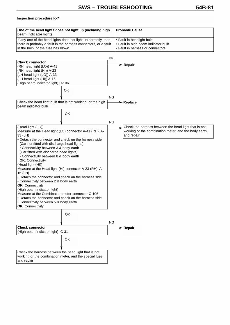
SWS – TROUBLESHOOTING 54B-81
Check connector(RH head light (LO)) A-41(RH head light (HI)) A-23(LH head light (LO)) A-33(LH head light (HI)) A-16(High beam indicator light) C-106
Check the head light bulb that is not working, or the highbeam indicator bulb
(Head light (LO))Measure at the Head light (LO) connector A-41 (RH), A-33 (LH)• Detach the connector and check on the harness side
(Car not fitted with discharge head lights)• Connectivity between 3 & body earth(Car fitted with discharge head lights)• Connectivity between 8 & body earthOK: Connectivity
(Head light (HI))Measure at the Head light (HI) connector A-23 (RH), A-16 (LH)• Detach the connector and check on the harness side• Connectivity between 2 & body earthOK: Connectivity(High beam indicator light)Measure at the Combination meter connector C-106• Detach the connector and check on the harness side• Connectivity between 5 & body earthOK: Connectivity
Check connector(High beam indicator light) C-31
Check the harness between the head light that is notworking or the combination meter, and the special fuse,and repair
Check the harness between the head light that is notworking or the combination meter, and the body earth,and repair
Inspection procedure K-7
One of the head lights does not light up (including highbeam indicator light)
Probable Cause
If any one of the head lights does not light up correctly, thenthere is probably a fault in the harness connectors, or a faultin the bulb, or the fuse has blown.
• Fault in headlight bulb• Fault in high beam indicator bulb• Fault in harness or connectors
Replace
Repair
OK
OK
OK
OK
NG
NG
NG
NG
Repair

SWS – TROUBLESHOOTING54B-82
Inspection procedure K-8
Check connectors(Tail light RH) F-10(Tail light LH) F-15(Position light RH) A-41(Position light LH) A-33(Licence plate light RH) F-12(Licence plate light LH) F-13
Check connectors(Tail light RH) C-215, C-209, C-07, C-31(Tail light LH) C-29, C-31(Licence plate light) F-14, C-29, C-31
Check the harness between the rear combination light,front combination light or licence plate light that is notworking, and the special fuse, and repair
(Licence plate light)Check connector F-14
Check the harness between the rear combination light,front combination light or licence plate light that is notworking, and the body earth, and repair.
Check the head light bulb that is not working
(Tail light)Measure at the Rear combination light connector F-10(RH) and F-15 (LH)• Detach the connector and check on the harness side• Connectivity between 5 & body earthOK: Connectivity(Position light)Measure at the Front combination light connector A-41(RH) A-33(LH)• Detach the connector and check on the harness side(Car not fitted with discharge headlights)• Connectivity between 3 & body earth(Car fitted with discharge headlights)• Connectivity between 7 & body earthOK: Connectivity(License plate light)Measure at the at the Licence plate light connector F-12(RH), F-13(LH) • Detach the connector and check on the harness side• Connectivity between 1 & body earthOK: Connectivity
One of the tail lights, position lights, or licence platelights does not light up
Probable Cause
If any one of the tail lights, position lights or licence platelights does not light up correctly, then there is probably a faultin the harness connectors, or a fault in the bulb, or the fusehas blown.
• Fault in tail light bulb• Fault in position light• Fault in licence plate light bulb• Fault in harness or connectors
OK
NG
NG
NG
OK
OK
OK
NG
OKNG
Repair
Repair
Replace
Repair

SWS – TROUBLESHOOTING 54B-83
Are the tail lights and head lights working normally?
SWS monitor service data(Function by Diagnosis) Lighting: Fog light• Ignition switch: ON• Tail light switch: ON• Fog light switch: ONItem No. Item Name Normal value(a) 30 Ignition SW IG1 ON(b) 36 Fog light ONOK: Normal value displayed for all
Check connectors A-06X
Check fog light relay(See Chap 54A Fog lights *)
Measure at the Fog light relay connector A-06X• Remove the relay, and check on the relay box side• Voltage between 2 and body earth• Voltage between 4 and body earthOK: Battery voltage
Check connectors A-12X
Check the harness between the fog light relay and thefront ECU
Confirm the trouble symptoms
Transient problem
Check the head lights and tail lights (See Chart ofTrouble Symptoms)
To Inspection procedure R-2 Ignition switch (IG1) signalnot input (p.54B-96)
To Inspection procedure R-18 Fog light switch signal notinput (p.54B-110)
Check the harness between the fog light relay and thespecial fuse, and repair.
Replace the front ECU
Inspection procedure L-1
Note: *: See ’00-5 Lancer Sedia Servicing Manual (No. 1036K00)
Fog lights do not light up correctly Probable Cause
If any one of the fog lights does not light up correctly, but thetail lights and head lights are working normally, then there isprobably a problem in the fog light switch input circuit system,a problem in the fog light relay, or a fault in the front ECU.
• Fault in fog light switch• Fault in fog light relay• Fault in front ECU• Fault in harness or connectors
YES
OK
OK
OK
OK
OK
OK
OK
NO
NG (a)
NG (b)
NG
NG
NG
NG
NG
NG
Repair
Repair
Replace
Repair

SWS – TROUBLESHOOTING54B-84
Inspection procedure L-2
Check connectors(Fog light RH) A-40(Fog light LH) A-35(Fog light indicator light) C-108, C-106
Check the fog light bulb or fog light indicator bulb that isnot working
Measure at the Fog light connector A-40 (RH), A-35 (LH),or the Fog light indicator light connector C-108
• Detach the connector and check on the harness side(Fog light)
• Connectivity between 2 & body earth(Fog light indicator light)
• Connectivity between 48 & body earthOK: Connectivity
(Fog light indicator light)Check connectors C-31
Check the harness between the fog light or fog lightindicator light that is not working, and the fog light relay,and repair
Check the harness between the fog light or fog lightindicator light which is not working, and that body earth,and repair
One of the fog lights does not light up (including fog light indicator light) Probable Cause
If any one of the fog lights does not light up normally, then there is probably afault in the harness/connectors, or a fault in the bulb
• Fault in fog light bulb• Fault in harness or connectors
OK
OK
OK
OK
NG
NG
NG
NG
Repair
Replace
Repair

SWS – TROUBLESHOOTING 54B-85
Are the hazard lights working normally?
Check connectors C-224
Measure at ETACS-ECU connector C-224• Detach the connector, and measure on the
junction box side• Voltage between 11 & body earthOK: Battery voltage
Check connector C-31
Check the harness betweenETACS-ECU connector and thebattery, and repair
Confirm the trouble symptoms
Transient problem
To Inspection procedure R-2 Ignition switch (IG1) signalnot input (p.54B-96)
Transient problem
Confirm the troublesymptoms
Replace the ETACS-ECU
To Inspection procedure R-5 RH turn indicator lightswitch signal not input (p.54B-99)
To Inspection procedure R-5 LH turn indicator light switchsignal not input (p.54B-99)
Replace the ETACS-ECU
SWS monitor service data(Function by Diagnosis) Turn indicator lights: R turnsignal• Turn indicator light switch: RH• Ignition switch: ONItem No. Item Name Normal state(a) 30 Ignition SW IG1 ON(b) 10 RH turn indicator SW ONOK: Normal value displayed for all
SWS monitor service data(Function by Diagnosis) Turn indicator lights: L turnsignal• Turn indicator light switch: LH• Ignition switch: ONItem No. Item Name Normal state
11 LH turn indicator SW ONOK: Normal value displayed
Inspection procedure M-1
Turn indicator lights do not light up Probable Cause
If none of the turn indicator lights is working, then there isprobably a problem in the ignition switch (IG1) or turnindicator light switch input circuit system, or a fault in theETACS-ECU.
• Fault in column switch• Fault in ETACS-ECU • Fault in harness or connectors
YES NO
OK
OK
NG
OK
NG
NG
NGOK
Repair
Repair
NG (a)
NG (b)
NG
OK
NG
OK
OK

SWS – TROUBLESHOOTING54B-86
Inspection procedure M-2
Are the turn indicator lights working normally?
SWS monitor service dataETACS switch data• Hazard switch: ONItem No. Item Name Normal state
04 Hazard light SW ONOK: Normal value displayed
Confirm the trouble symptoms
Transient problem
To Inspection procedure M-1 Turn indicator lights do notlight up (p.54B-85)
To Inspection procedure R-13 Hazard light switch signalnot input (p.54B-105)
Replace the ETACS-ECU
Hazard lights do not light up Probable Cause
If the hazard lights do not light up, then there is probably aproblem in the hazard light switch input circuit system, or afault in the ETACS-ECU.
• Fault in hazard light switch• Fault in ETACS-ECU • Fault in harness or connectors
YES
OK
OK
NG
NG
NO

SWS – TROUBLESHOOTING 54B-87
Check connectors(Front turn signal light RH) A-41(Front turn signal light LH) A-33(Side turn signal light RH) A-01(Side turn signal light LH) A-04(Rear turn signal light RH) F-10(Rear turn signal light LH) F-15(Turn signal dashboard indicator light RH) C-108(Turn signal dashboard indicator light LH) C-106, C-108
Check the turn signal light bulb that is not working
(Front turn signal light)Measure at the Front combination light connector A-41(RH), A-33(LH)• Detach the connector and check on the harness side(Car not fitted with discharge head lights)• Connectivity between 3 & body earth(Car fitted with discharge head lights)• Connectivity between 7 & body earthOK: Connectivity(Side turn signal light)Measure at the Side turn signal light connector A-01(RH),A-04(LH)• Detach the connector and check on the harness side• Connectivity between 1 & body earthOK: Connectivity(Rear turn signal light)Measure at the Rear combination light connector F-10(RH), F-15(LH)• Detach the connector and check on the harness side• Connectivity between 5 & body earthOK: Connectivity(Turn signal dashboard indicator light)Measure at the Combination meter connector C-108• Detach the connector and check on the harness side• Connectivity between 48 & body earthOK: Connectivity
Check the harness between the body earth, and the non-functioning front combination light, side turn signal light,rear combination light, or combination meter, and repair
Check connectors(Front turn signal light RH) C-31, C-209(Front turn signal light LH) C-31, C-209(Side turn signal light RH) C-115, C-209(Side turn signal light LH) C-31, C-209(Rear turn signal light RH) C-215(Rear turn signal light LH) C-29, C-209(Turn signal dashboard indicator light RH) C-212(Turn signal dashboard indicator light LH) C-212
Check the harness between the ETACS-ECU, and thenon-functioning front combination light, side turn signallight, rear combination light, or combination meter, andrepair
Inspection procedure M-3
One of the turn indicator lights does not light up Probable Cause
If one of the turn indicator lights is not working correctly, thenthere is probably a fault in the harness/connector, or a fault inthe bulb.
• Fault in turn indicator light bulb• Fault in harness or connectors
OK
OK
NG
NG
NG
OK
Repair
Replace
OKNG
Repair

SWS – TROUBLESHOOTING54B-88
Inspection procedure N-1
Front interior light and/or rear interior light does not light up orswitch off correctly (vehicle not fitted with sunroof)
Probable Cause
(Vehicle not fitted with keyless entry)The front interior light and/or rear interior light (in vehicles not fittedwith a sunroof) switches on/off by determining the following inputsignals in the ETACS-ECU.• Ignition switch (IG1)• Key reminder switch• Driver’s door switch• All door switch• Driver’s door lock actuatorIf the lights do not work correctly, then there is probably a problem inthe input circuit system for these signals, or a fault in the ETACS-ECU.It is possible that the delay switch off time has been set to “0 seconds”by the adjustment function.
• Fault in key reminder switch• Fault in door switch• Fault in driver’s door lock actuator• Fault in ETACS-ECU • Fault in harness or connectors
(Vehicle fitted with keyless entry)The front interior light and/or rear interior light (in vehicles not fittedwith a sunroof) switches on/off by determining the following inputsignals in the ETACS-ECU.Moreover, since the interior lights are switched off by the interior lightautomatic cut-off function, the input signal from this interior lightautomatic cut-off function must be checked at the same time.• Ignition switch (ACC)• Ignition switch (IG1)• Key reminder switch• Driver’s door switch• All door switch• Driver’s door lock actuator• Generic fuse No. 17If the lights do not work correctly, then there is probably a problem inthe input circuit system for these signals, a malfunction in the interiorlight automatic cut-off function, or a fault in the ETACS-ECU.It is possible that the delay switch off time has been set to “0 seconds”by the adjustment function.
• Fault in key reminder switch• Fault in door switch• Fault in driver’s door lock actuator• Fault in ETACS-ECU • Fault in harness or connectors

SWS – TROUBLESHOOTING 54B-89
(Vehicle not fitted with keyless entry)
Is the interior light delay switch off time period set to “7.5seconds”, “15 seconds”, “30 seconds” or “60 seconds”?
SWS monitor ECU check• Ignition switch: OFFETACS-ECUOK: “OK” is displayed
SWS monitor service data(Communications data) ETACS-ECU • Ignition switch: OFF• Driver’s door: Open (but closed when checking Item
No.38)• All doors: Open (but closed when checking Item No.32)Item No. Item Name Normal state(a) 30 Ignition SW IG1 OFF(b) 32 Driver’s door SW ON(c) 38 Security alarm ONOK: Normal state displayed for all
SWS monitor service dataETACS switch data• Ignition switch: OFF (key inserted)Item No. Item Name Normal state
03 Key reminder SW ONOK: Normal state displayed
Check connector C-216
Check at Junction box connector C-216• Detach the connector and check at the junction box
side• Voltage between 3 & body earthOK: Battery voltage
Check the front interior light bulb and the rear interiorlight bulb (vehicle not fitted with sunroof)
Check connectors C-216, C-224, D-04
Confirm the troublesymptoms
Check the harness between the ETACS-ECU and thefront interior light
Confirm the troublesymptoms
Check connector D-06
Check the harness between the ETACS-ECU and therear interior light
Use the adjustment function to set the interior light delayswitch off time period to “7.5 seconds”, “15 seconds”, “30seconds” or “60 seconds” (p.54B-118)
To Inspection procedure A-3 No communication withETACS-ECU (p.54B-28)
To Inspection procedure R-2 Ignition switch (IG1) signalnot input (p.54B-96)
To Inspection procedure R-4 Driver’s door switch signalnot input (p.54B-98)
To Inspection procedure R-14 All door switch signals notinput (except driver’s door) (p.54B-106)
To Inspection procedure R-11 Key reminder switch signalnot input (p.54B-103)
Check connectors C-224, C-211, C-32
Confirm the trouble symptoms
Check the harness between the ETACS-ECU and thebattery
Replace the ETACS-ECU
Confirm the trouble symptoms
Replace the ETACS-ECU
Confirm the trouble symptoms
Replace the ETACS-ECU
OK (Vehiclefitted withsunroof)
OK (Vehicle not fitted with sunroof)
RepairNG
YES
OK
OK
OK
OK
OK
OK
OK
NG
OK
NG
NG
NG
NG
OKNG
Replace
Repair
Repair
Repair
NG
NGRepair
NO
NG
NG (a)
NG (b)
NG (c)
NG
OK
NG
NG NG
NG
Repair
Repair
NG
NG

SWS – TROUBLESHOOTING54B-90
(Vehicle fitted with keyless entry)
Is the interior light delay switch off time period set to “7.5seconds”, “15 seconds”, “30 seconds” or “60 seconds”?
SWS monitor ECU check• Ignition switch: OFFETACS-ECUOK: “OK” is displayed
SWS monitor service data(Communications data) ETACS-ECU • Ignition switch: OFF• Driver’s door: Open (but closed when checking Item
No.38)• All doors: Open (but closed when checking Item No.32)Item No. Item Name Normal state(a) 30 Ignition SW IG1 OFF(b) 32 Driver’s door SW ON(c) 38 Security alarm ONOK: Normal state displayed for all
SWS monitor service dataETACS switch data• Ignition switch: OFF (key inserted)Item No. Item Name Normal state
30 Key reminder SW ONOK: Normal state displayed
MUT-II/III pulse checkGeneric fuse No.17OK MUT-II/III buzzer sounds once
Check the front interior light bulb and the rear interiorlight bulb (vehicle not fitted with sunroof)
Check connectors C-224, C-216, D-04
Confirm the troublesymptoms
Check the harness between the ETACS-ECU and therear personal light
Check connectors D-06
Confirm the troublesymptoms
Check the harness between the ETACS-ECU and therear interior light
Use the adjustment function to set the interior light delayswitch off time period to “7.5 seconds”, “15 seconds”, “30seconds” or “60 seconds” (p.54B-118)
To Inspection procedure A-3 No communication withETACS-ECU (p.54B-28)
To Inspection procedure R-1 Ignition switch (ACC) signalnot input (p.54B-96)
To Inspection procedure R-2 Ignition switch (IG1) signalnot input (p.54B-96)
To Inspection procedure R-4 Driver’s door switch signalnot input (p.54B-98)
To Inspection procedure R-14 All door switch signals notinput (except driver’s door) (p.54B-106)
To Inspection procedure R-11 Key reminder switch signalnot input (p.54B-103)
To Inspection procedure R-19 Generic fuse No.17 loaduse signal not detected (p.54B-111)
Confirm the trouble symptoms
Replace the ETACS-ECU
Confirm the trouble symptoms
Replace the ETACS-ECU
OK (Vehicle not fitted withsunroof)
OK (Vehiclefitted withsunroof)
YES
OK
OK
OK
OK
OK
OK
NG
OK
NG
NG
NG
NG
NG
OK
Replace
Repair
Repair
Repair
Repair
NO
NO
NG (a)
NG (b)
NG (c)
NG (d)
NG
NG
NG
OK
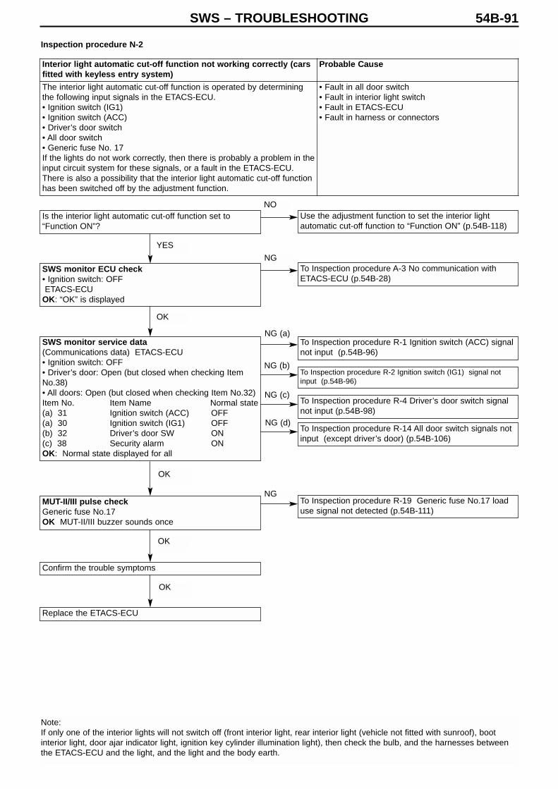
SWS – TROUBLESHOOTING 54B-91
Is the interior light automatic cut-off function set to“Function ON”?
SWS monitor ECU check• Ignition switch: OFFETACS-ECU
OK: “OK” is displayed
SWS monitor service data(Communications data) ETACS-ECU • Ignition switch: OFF• Driver’s door: Open (but closed when checking ItemNo.38)• All doors: Open (but closed when checking Item No.32)Item No. Item Name Normal state(a) 31 Ignition switch (ACC) OFF(a) 30 Ignition switch (IG1) OFF(b) 32 Driver’s door SW ON(c) 38 Security alarm ONOK: Normal state displayed for all
MUT-II/III pulse checkGeneric fuse No.17OK MUT-II/III buzzer sounds once
Confirm the trouble symptoms
Replace the ETACS-ECU
Use the adjustment function to set the interior lightautomatic cut-off function to “Function ON” (p.54B-118)
To Inspection procedure A-3 No communication withETACS-ECU (p.54B-28)
To Inspection procedure R-1 Ignition switch (ACC) signalnot input (p.54B-96)
To Inspection procedure R-2 Ignition switch (IG1) signal notinput (p.54B-96)
To Inspection procedure R-4 Driver’s door switch signalnot input (p.54B-98)
To Inspection procedure R-14 All door switch signals notinput (except driver’s door) (p.54B-106)
To Inspection procedure R-19 Generic fuse No.17 loaduse signal not detected (p.54B-111)
Inspection procedure N-2
Note: If only one of the interior lights will not switch off (front interior light, rear interior light (vehicle not fitted with sunroof), bootinterior light, door ajar indicator light, ignition key cylinder illumination light), then check the bulb, and the harnesses betweenthe ETACS-ECU and the light, and the light and the body earth.
Interior light automatic cut-off function not working correctly (carsfitted with keyless entry system)
Probable Cause
The interior light automatic cut-off function is operated by determiningthe following input signals in the ETACS-ECU.• Ignition switch (IG1)• Ignition switch (ACC)• Driver’s door switch• All door switch• Generic fuse No. 17If the lights do not work correctly, then there is probably a problem in theinput circuit system for these signals, or a fault in the ETACS-ECU.There is also a possibility that the interior light automatic cut-off functionhas been switched off by the adjustment function.
• Fault in all door switch• Fault in interior light switch• Fault in ETACS-ECU • Fault in harness or connectors
YES
OK
OK
OK
OK
NO
NG
NG (a)
NG (b)
NG (c)
NG (d)
NG

SWS – TROUBLESHOOTING54B-92
Inspection procedure O-1
Do the interior lights switch on normally?
SWS monitor ECU check• Ignition switch: OFFETACS-ECUOK: “OK” is displayed
Check connectors C-108, C-106, C-225, C-110
Check the harness between the combination meter andthe ETACS-ECU
Confirm the trouble symptoms
Transient problem
To Inspection procedure N-1 Interior lights do not light upor switch off correctly (p.54B-88)
To Inspection procedure A-3 No communication withETACS-ECU (p.54B-28)
Replace the ETACS-ECU
Door ajar indicator light does not light up or switch off correctly Probable Cause
The door ajar indicator light is lit up by determining the following inputsignals in the ETACS-ECU.• Driver’s door switch• All door switchIf the light does not work correctly, then there is probably a problem in theinput circuit system for these signals, or a fault in the ETACS-ECU.
• Fault in all door switch• Fault in combination meter• Fault in ETACS-ECU • Fault in harness or connectors
OK
OK
OK
OK
OK
NO
NO
NG
NG
Repair
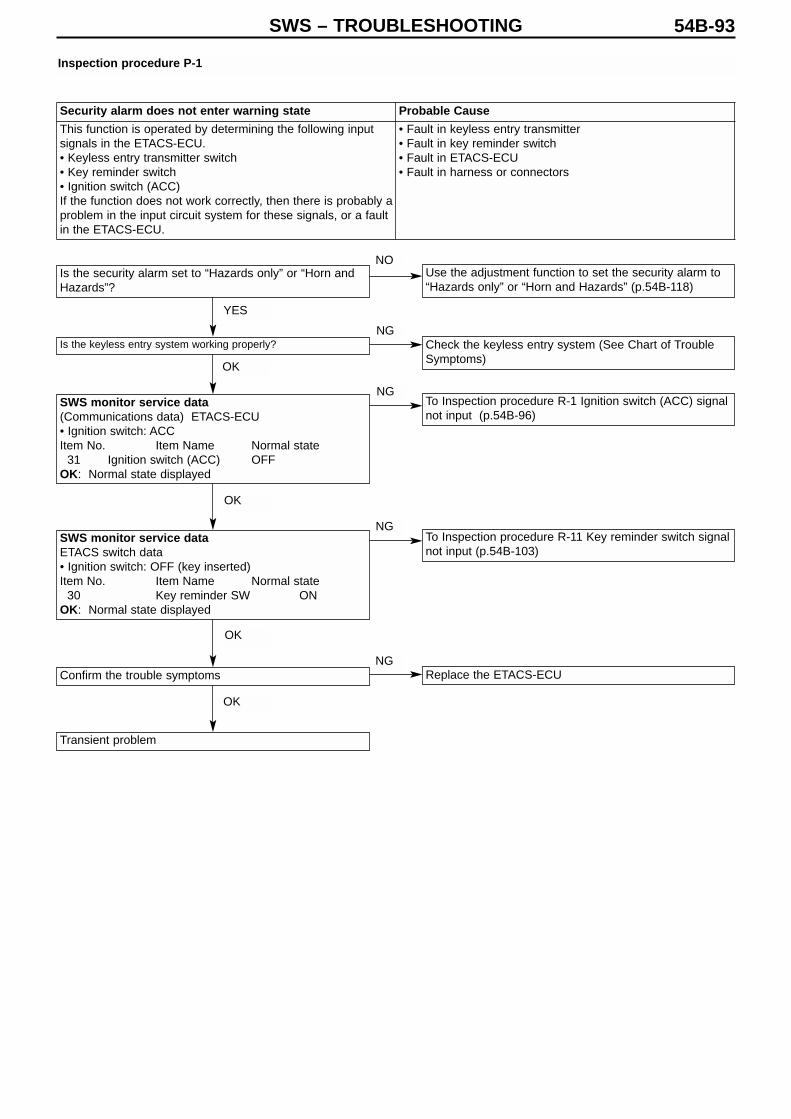
SWS – TROUBLESHOOTING 54B-93
Is the security alarm set to “Hazards only” or “Horn andHazards”?
Is the keyless entry system working properly?
SWS monitor service data(Communications data) ETACS-ECU • Ignition switch: ACCItem No. Item Name Normal state
31 Ignition switch (ACC) OFFOK: Normal state displayed
SWS monitor service dataETACS switch data• Ignition switch: OFF (key inserted)Item No. Item Name Normal state
30 Key reminder SW ONOK: Normal state displayed
Confirm the trouble symptoms
Transient problem
Use the adjustment function to set the security alarm to“Hazards only” or “Horn and Hazards” (p.54B-118)
Check the keyless entry system (See Chart of TroubleSymptoms)
To Inspection procedure R-1 Ignition switch (ACC) signalnot input (p.54B-96)
To Inspection procedure R-11 Key reminder switch signalnot input (p.54B-103)
Replace the ETACS-ECU
Inspection procedure P-1
Security alarm does not enter warning state Probable Cause
This function is operated by determining the following inputsignals in the ETACS-ECU.• Keyless entry transmitter switch• Key reminder switch• Ignition switch (ACC)If the function does not work correctly, then there is probably aproblem in the input circuit system for these signals, or a faultin the ETACS-ECU.
• Fault in keyless entry transmitter• Fault in key reminder switch• Fault in ETACS-ECU • Fault in harness or connectors
YES
OK
OK
OK
OK
NO
NG
NG
NG
NG

SWS – TROUBLESHOOTING54B-94
Inspection procedure P-2
Is the security alarm set to “Hazards only” or “Horn andHazards”?
SWS monitor ECU check• Ignition switch: OFFETACS-ECUOK: “OK” is displayed
SWS monitor service data(Communications data) ETACS-ECU• All doors: respectively opened and closedItem No. Item Name Normal state38 Security alarm ONOK: Normal state displayed
Confirm the trouble symptoms
Transient problem
Is the security alarm set to “Hazards only” or “Horn andHazards”?
Are the hazard lights working normally?
SWS monitor ECU check• Ignition switch: OFFETACS-ECUOK: “OK” is displayed
Confirm the trouble symptoms
Transient problem
Use the adjustment function to set the security alarm to“Hazards only” or “Horn and Hazards” (p.54B-118)
To Inspection procedure M-2 Hazard lights do not lightup (p.54B-86)
To Inspection procedure A-3 No communication withETACS-ECU (p.54B-28)
Replace the ETACS-ECU
Use the adjustment function to set the security alarm to“Hazards only” or “Horn and Hazards” (p.54B-118)
To Inspection procedure A-3 No communication withETACS-ECU (p.54B-28)
To Inspection procedure R-14 All door switch signals notinput (except driver’s door) (p.54B-106)
Replace the ETACS-ECU
Inspection procedure P-3
Interior warning does not operate correctly when security alarm operates Probable Cause
This function is operated by determining the all door switch input signal in theETACS-ECU.If the function does not work correctly, then there is probably a problem in theinput circuit system for this signal, or a fault in the ETACS-ECU.
• Fault in all door switch• Fault in ETACS-ECU • Fault in harness or connectors
Hazard lights do not flash when security alarm operates Probable Cause
This function is operated by the ETACS-ECU.If the hazard lights do not flash properly, then there isprobably a fault in the ETACS-ECU.
• Fault in ETACS-ECU • Fault in harness or connectors
YES
OK
OK
OK
YES
YES
OK
OK
NO
NG
NG
NG
NO
NO
NG
NG

SWS – TROUBLESHOOTING 54B-95
Is the security alarm set to “Horn and Hazards”?
SWS monitor ECU check• Ignition switch: OFFETACS-ECUOK: “OK” is displayed
Is the horn working normally?
Check connector A-07X
Check the horn relay (See Chap. 54A Horn*)
Measure at the Horn relay connector A-07X• Detach the horn relay and measure at the relay box• Voltage between 2 & body earth• Voltage between 4 & body earthOK: Battery voltage
Check connectors A-20, A-22
Check the harness between the horn (LO) or (HI) andthe horn relay
Confirm the trouble symptoms
Transient problem
Use the adjustment function to set the security alarm to“Horn and Hazards” (p.54B-118)
To Inspection procedure A-3 No communication withETACS-ECU (p.54B-28)
Check connectors A-07X, C-31, C-06, C-226
Check the harness between the horn relay and theETACS-ECU
Confirm the trouble symptoms
Transient problem Replace the ETACS-ECU
Check the harness between the horn relay and thespecial fuse, and repair
Replace the ETACS-ECU
Inspection procedure P-4
Horn does not sound when security alarm operates Probable Cause
This function is operated by the ETACS-ECU.If the horn does not sound, then there is probably a fault inthe ETACS-ECU.
• Fault in ETACS-ECU • Fault in harness or connectors
*: See ’00-5 Lancer Sedia Servicing Manual (No. 1036K00)
YES
OK
NO
OK NG
NGOK
OK
OK
OK
OK
Repair
Replace
OK
OK
OK
NG
NG
NG
Repair
Repair
Repair
Repair
NO
NG
YES
NG
NG
NG
NG

SWS – TROUBLESHOOTING54B-96
Inspection procedure R-1
Check connector C-224
Check connector C-224
Measure at the ETACS-ECU connector C-224• Detach the connector and measure at the junction box
side• Ignition switch: ON• Voltage between 8 & body earthOK: Battery voltage
SWS monitor service data(Communications data) ETACS-ECU• Ignition switch: ACCItem No. Item Name Normal state
30 Ignition SW IG1 ONOK: Normal state displayed
Replace the ETACS-ECU
Check connector C-210
Check the harness between the ETACS-ECU and theignition switch (IG1), and repair
Transient problem
Measure at the ETACS-ECU connector C-224• Detach the connector and measure at the junction box
side• Ignition switch . ACC• Voltage between 4 & body earthOK: Battery voltage
SWS monitor service data(Communications data) ETACS-ECU• Ignition switch: ACCItem No. Item Name Normal state
31 Ignition SW ACC ONOK: Normal state displayed
Replace the ETACS-ECU
Check connector C-210
Transient problem
Check the harness between the ETACS-ECU and theignition switch (ACC), and repair
Inspection procedure R-2
Ignition switch (ACC) signal not input Probable CauseIf there is a problem in the ignition switch (ACC) input signal,then the ignition switch (ACC) signal will cease to be output tothe SWS communications line.
• Fault in ETACS-ECU • Fault in harness or connectors
Ignition switch (IG1) signal not input Probable Cause
If there is a problem in the ignition switch (IG1) input signal,then the ignition switch (IG1) signal will cease to be output tothe SWS communications line.
• Fault in ETACS-ECU • Fault in harness or connectors
OK
OK
NG
NG
NG
Repair
OK NG
Repair
OK
OK
OK
NG
Repair
Repair
NG
NG
OK
OK OK

SWS – TROUBLESHOOTING 54B-97
Check connectors B-132
Check the reversing light switch
Check connector C-226
Check connectors B-31, C-22, C-119
Check the harness between the reversing light switchand the ETACS-ECU.
Transient problem Replace the ETACS-ECU
Check connectors B-21, C-21, C-209, C-210
Check the harness between the reversing light switchand the ignition switch (IG1), and repair
Measure at the ETACS-ECU connector C-226• Detach the connector and measure at the harness side• Shift position: R• Ignition switch: ON• Voltage between 39 & body earthOK: Battery voltage
Measure at the Reversing light switch connector B-132• Detach the connector and measure at the harness side• Ignition switch: ON• Voltage between 2 & body earthOK: Battery voltage
SWS monitor service data(Communications data) ETACS-ECU• Ignition switch: ON• Shift position: RItem No. Item Name Normal state
41 Inhibitor SW (R) ONOK: Normal state displayed
Inspection procedure R-3
Reversing light switch signal not input Probable Cause
If there is a problem in the reversing light switch input signal,then the reversing light switch signal will cease to be output tothe SWS communications line.
• Fault in the reversing light• Fault in ETACS-ECU • Fault in harness or connectors
OK
OK
OK
NG
OK
OK
NG
NG
NG
OK
Repair
Replace
Repair
OK
OK
NG
NG
NG
NG
Repair
Repair

SWS – TROUBLESHOOTING54B-98
Inspection procedure R-4
Check the state of installation of the driver’s door switchon the body
Check connector D-01
Check the driver’s door switch (see Chap. 42 Doors*)
Check connectors C-215, C-224
Check the harness between the driver’s door switch andthe ETACS-ECU
SWS monitor service data(Communications data) ETACS-ECU• Driver’s door: OpenItem No. Item Name Normal state
32 Front door SW RH ONOK: Normal state displayed
Replace the ETACS-ECU
Transient problem
Note: *: See ’00-5 Lancer Sedia Servicing Manual (No. 1036K00)
Driver’s door switch signal not input Probable Cause
If there is a problem in the input signal for the driver’s doorswitch, then this driver’s door switch signal will cease to beoutput to the SWS communications line.
• Fault in driver’s door switch• Fault in ETACS-ECU • Fault in harness or connectors
OK
NG
NG
NG
NG
NG
OK
OK
OK
OK
OK
NG
Repair
Repair
Replace
Repair
Repair

SWS – TROUBLESHOOTING 54B-99
Check connectors: Wiper / washer switch, lightingswitch, switch body
Check column switch (light switch)(Chap. 54A – Column Switches *)
SWS monitor ECU check• Ignition switch: OFFColumn ECUOK: “OK” is displayed
SWS monitor service data(Communications data) Column ECUItem No. Item Name Normal state
00 Head light SW ON01 Tail light SW ON02 Dimmer SW ON03 Passing SW ON10 Turn signal RH SW ON11 Turn signal LH SW ON
OK: Normal states displayed at respective switchpositions
Replace the column switch
To Inspection procedure A-2 No communication withcolumn ECU (p.54B-27)
Transient problem
Inspection procedure R-5
Note: *: See ’00-5 Lancer Sedia Servicing Manual (No. 1036K00)
Column switches• Tail light switch signal not input• Headlight switch signal not input• Dimmer switch signal not input • Passing switch signal not input • LH turn indicator light switch signal not input • RH turn indicator light switch signal not input
Probable Cause
If there is a problem in the input signal of the column switch(lighting switch), then the column switch signal (light switchsignal) will cease to be output to the SWS communicationsline.
• Fault in column switch • Fault in harness or connectors
OK
NG
NG
NG
OK
OK
OK
NG
Repair
Replace
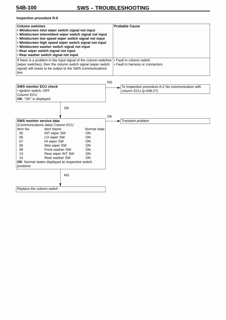
SWS – TROUBLESHOOTING54B-100
Inspection procedure R-6
SWS monitor ECU check• Ignition switch: OFFColumn ECUOK: “OK” is displayed
SWS monitor service data(Communications data) Column ECUItem No. Item Name Normal state
05 INT wiper SW ON06 LO wiper SW ON07 HI wiper SW ON08 Mist wiper SW ON08 Front washer SW ON13 Rear wiper INT SW ON14 Rear washer SW ON
OK: Normal states displayed at respective switchpositions
Replace the column switch
To Inspection procedure A-2 No communication withcolumn ECU (p.54B-27)
Transient problem
Column switches• Windscreen mist wiper switch signal not input • Windscreen intermittent wiper switch signal not input • Windscreen low speed wiper switch signal not input • Windscreen high speed wiper switch signal not input • Windscreen washer switch signal not input • Rear wiper switch signal not input • Rear washer switch signal not input
Probable Cause
If there is a problem in the input signal of the column switches(wiper switches), then the column switch signal (wiper switchsignal) will cease to be output to the SWS communicationsline.
• Fault in column switch • Fault in harness or connectors
OK
NG
OK
NG
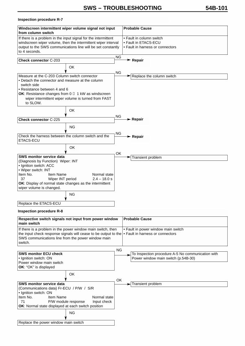
SWS – TROUBLESHOOTING 54B-101
Check connector C-203
Check connector C-225
SWS monitor ECU check• Ignition switch: ONPower window main switchOK: “OK” is displayed
SWS monitor service data(Communications data) Fr-ECU / P/W / S/R• Ignition switch: ONItem No. Item Name Normal state
71 P/W module response Input checkOK: Normal state displayed at each switch position
Replace the power window main switch
To Inspection procedure A-5 No communication withPower window main switch (p.54B-30)
Transient problem
Check the harness between the column switch and theETACS-ECU
SWS monitor service data(Diagnosis by Function) Wiper: INT• Ignition switch: ACC• Wiper switch: INTItem No. Item Name Normal state
37 Wiper INT period 2.4 – 18.0 sOK: Display of normal state changes as the intermittentwiper volume is changed.
Replace the ETACS-ECU
Replace the column switch
Transient problem
Measure at the C-203 Column switch connector • Detach the connector and measure at the column
switch side• Resistance between 4 and 6OK: Resistance changes from 0 → 1 kW as windscreen
wiper intermittent wiper volume is turned from FASTto SLOW.
Inspection procedure R-7
Inspection procedure R-8
Windscreen intermittent wiper volume signal not inputfrom column switch
Probable Cause
If there is a problem in the input signal for the intermittentwindscreen wiper volume, then the intermittent wiper intervaloutput to the SWS communications line will be set constantlyto 4 seconds.
• Fault in column switch• Fault in ETACS-ECU • Fault in harness or connectors
Respective switch signals not input from power windowmain switch
Probable Cause
If there is a problem in the power window main switch, thenthe input check response signals will cease to be output to theSWS communications line from the power window mainswitch.
• Fault in power window main switch • Fault in harness or connectors
OK
OK
NG
OK
NG
OK
NG
NG
NG
NG
NG
OK
NG
OK
Repair
Repair
Repair
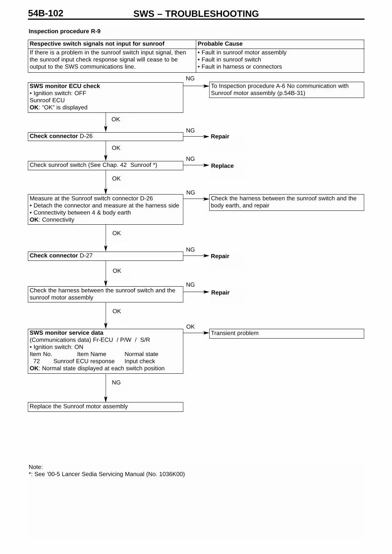
SWS – TROUBLESHOOTING54B-102
Inspection procedure R-9
SWS monitor ECU check• Ignition switch: OFFSunroof ECUOK: “OK” is displayed
Check connector D-26
Check sunroof switch (See Chap. 42 Sunroof *)
Measure at the Sunroof switch connector D-26• Detach the connector and measure at the harness side• Connectivity between 4 & body earthOK: Connectivity
Check connector D-27
Check the harness between the sunroof switch and thesunroof motor assembly
SWS monitor service data(Communications data) Fr-ECU / P/W / S/R• Ignition switch: ONItem No. Item Name Normal state
72 Sunroof ECU response Input checkOK: Normal state displayed at each switch position
Replace the Sunroof motor assembly
To Inspection procedure A-6 No communication withSunroof motor assembly (p.54B-31)
Check the harness between the sunroof switch and thebody earth, and repair
Transient problem
Note: *: See ’00-5 Lancer Sedia Servicing Manual (No. 1036K00)
Respective switch signals not input for sunroof Probable CauseIf there is a problem in the sunroof switch input signal, thenthe sunroof input check response signal will cease to beoutput to the SWS communications line.
• Fault in sunroof motor assembly• Fault in sunroof switch• Fault in harness or connectors
OK
OK
OK
OK
OK
OK
NG
NG
NG
NG
NG
NG
NG
OK
Repair
Replace
Repair
Repair

SWS – TROUBLESHOOTING 54B-103
SWS monitor ECU checkCentre displayOK: “OK” is displayed
Check the multi-centre display
Replace the multi-centre display
Check connector C-202
Check the key reminder switch (Chap. 54A Ignitionswitch *)
Measure at the Key reminder switch connector C-202• Detach the connector and measure at the harness side• Connectivity between 4 & body earthOK: Connectivity
Check connector C-226
Check the harness between the key reminder switch andthe ETACS-ECU
SWS monitor service dataETACS switch data• Ignition switch: OFF (key inserted)Item No. Item Name Normal state
03 Key reminder SW ONOK: Normal state displayed
Transient problem
Check connector C-107
Check the harness between the key reminder switch andthe body earth, and repair
Replace the ETACS-ECU
To Inspection procedure A-7 No communication withmulti-centre display (p.54B-32)
Transient problemSWS monitor service data(Communications data) Centre display• Ignition switch: ACCItem No. Item Name Normal state
62 Display input ONOK: Normal state displayed when audio operating stick ispressed, except for volume
Inspection procedure R-10
Inspection procedure R-11
Note: *: See ’00-5 Lancer Sedia Servicing Manual (No. 1036K00)
Respective switch signals not input for multi-centre display Probable Cause
If there is a problem in the multi-centre display, then the multi-centre display input check response signal will cease to beoutput to the SWS communications line.
• Fault in multi-centre display• Fault in harness or connectors
Key reminder switch signal not input Probable Cause
The input signal of the key reminder switch is used whendetermining the operation of the following functions.Therefore, if there is a problem in this input signal, then thesefunctions will not operate correctly.• Ignition key left in warning function• Key left in warning function• Keyless entry• Ignition key cylinder illumination light• Interior lights
• Fault in key reminder switch• Fault in ETACS-ECU • Fault in harness or connectors
OK
NG
NG
OKOK
NG
Repair, Replace
OK
OK
OK
OK NGRepair
OK
OK
Repair
Repair
Repair
Replace
OK
NG
NG
NG
NG
NG
NG
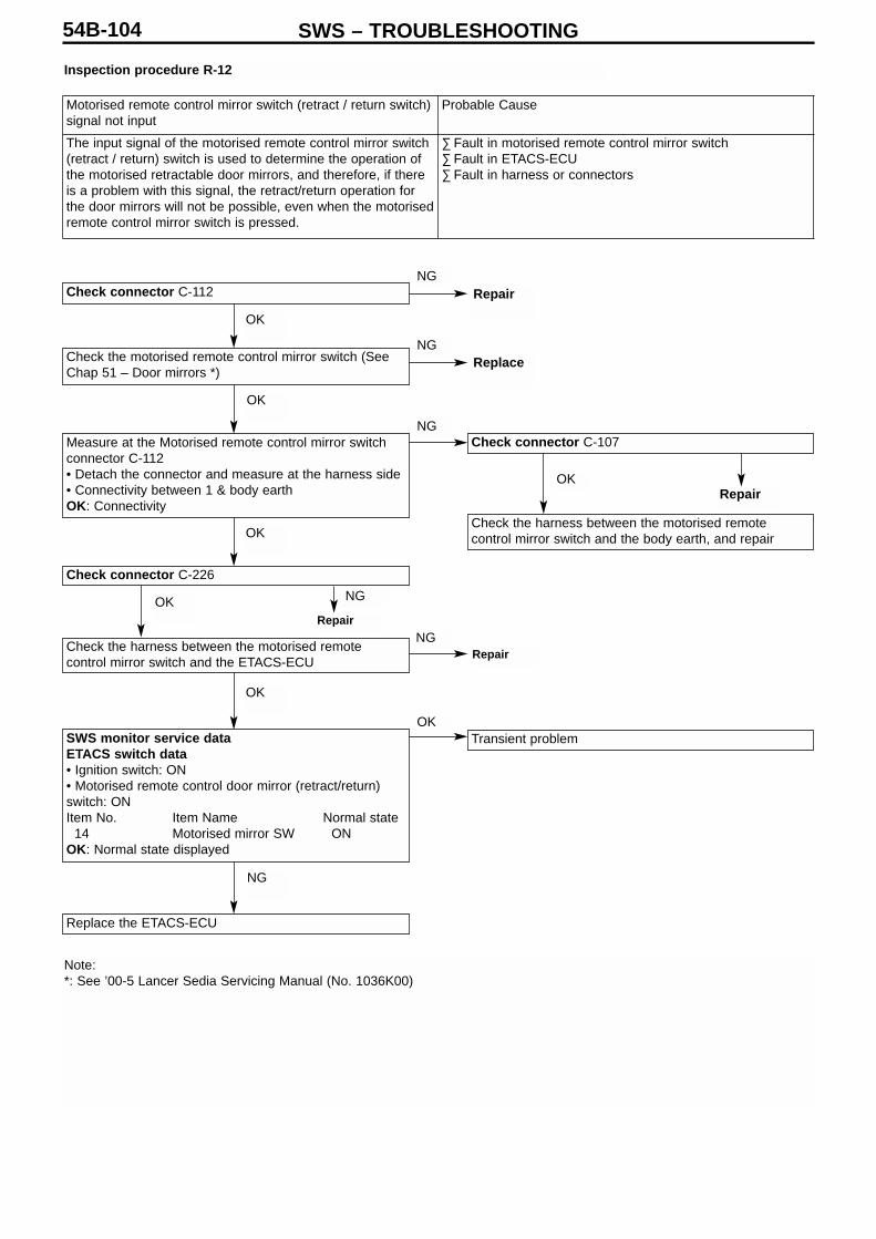
SWS – TROUBLESHOOTING54B-104
Inspection procedure R-12
Check connector C-112
Check the motorised remote control mirror switch (SeeChap 51 – Door mirrors *)
Measure at the Motorised remote control mirror switchconnector C-112• Detach the connector and measure at the harness side• Connectivity between 1 & body earthOK: Connectivity
Check connector C-226
Check the harness between the motorised remotecontrol mirror switch and the ETACS-ECU
SWS monitor service dataETACS switch data• Ignition switch: ON• Motorised remote control door mirror (retract/return)switch: ONItem No. Item Name Normal state
14 Motorised mirror SW ONOK: Normal state displayed
Replace the ETACS-ECU
Check connector C-107
Check the harness between the motorised remotecontrol mirror switch and the body earth, and repair
Transient problem
Note: *: See ’00-5 Lancer Sedia Servicing Manual (No. 1036K00)
Motorised remote control mirror switch (retract / return switch)signal not input
Probable Cause
The input signal of the motorised remote control mirror switch(retract / return) switch is used to determine the operation ofthe motorised retractable door mirrors, and therefore, if thereis a problem with this signal, the retract/return operation forthe door mirrors will not be possible, even when the motorisedremote control mirror switch is pressed.
∑ Fault in motorised remote control mirror switch∑ Fault in ETACS-ECU ∑ Fault in harness or connectors
OK
OK
OK
OK
NG
OK NG
Repair
Repair
NG
NG
OK
NG
NG
OK
Repair
Repair
Replace

SWS – TROUBLESHOOTING 54B-105
Check connectorsC-14 (Vehicle not fitted with multi-centre display)C-105 (Vehicle fitted with multi-centre display)
Check the hazard light switch (See Chap 54A Hazardlight switch *)
Check connector C-225
Check the harness between the hazard light switch andthe ETACS-ECU.
Transient problem
Check connector C-107
Check the harness between the hazard light switch andthe body earth, and repair
Replace the ETACS-ECU
Measure at the Hazard light switch connectorC-14 (Vehicle not fitted with multi-centre display)C-105 (Vehicle fitted with multi-centre display)• Detach the connector and measure at the harness side• Ignition switch: ON• Connectivity between 2 & body earthOK: Connectivity
SWS monitor service dataETACS switch data• Ignition switch: OFF• Hazard light switch : ONItem No. Item Name Normal state
04 Hazard light SW ONOK: Normal state displayed
Note: *: See ’00-5 Lancer Sedia Servicing Manual (No. 1036K00)
Inspection procedure R-13
Hazard light switch signal not input Probable Cause
The hazard light switch input signal is used to determine theoperation of the hazard lights, and therefore, if there is aproblem with this signal, then the hazard lights will not lightup.
• Fault in hazard light switch• Fault in ETACS-ECU • Fault in harness or connectors
OK
OK
OK
OK
OK
OK
NG
NG
NG
NGOK
NG
NG
NG
Repair
Replace
Repair
Repair
Repair

SWS – TROUBLESHOOTING54B-106
Inspection procedure R-14
SWS monitor service data(Communications data) ETACS-ECU• Driver’s door: OpenItem No. Item Name Normal state
32 Front door SW RH ONOK: Normal state displayed
Check the state of installation of the door switch on thebody
To Inspection procedure R-4 Driver’s door switch signalnot input (p.54B-98)
Transient problem
Check the door switch (See Chap. 42 Doors*)
Check the harnesses between the respective doorswitches and the ETACS-ECU
Replace the ETACS-ECU
Check connectors (Front passenger door) D-15(Rear left passenger door) D-09(Rear right passenger door) D-07
Check connectors (Front passenger door) C-29, C-212, C-224(Rear left passenger door) C-29, C-212, C-224(Rear right passenger door) C-215, C-224
SWS monitor service data(Communications data) ETACS• Doors: Respectively opened and closedItem No. Item Name Normal state
38 Security alarm ONOK: Normal state displayed
Note: *: See ’00-5 Lancer Sedia Servicing Manual (No. 1036K00)
All door switch signals not input (except driver’s door) Probable Cause
Because the input signals from all the door switches are usedto determine the operation of the following functions, thesefunctions will not work correctly if there is an error in the inputsignals.• Keyless entry system• Room lightThe driver’s door switch is connected internally via theETACS-ECU, so it should also be checked that there is nomalfunction in the driver’s door switch input signal.
• Fault in door switch• Fault in ETACS-ECU • Fault in harness or connectors
OK
NG
NG
NG
NG
NG
NG
OK
OK
OK
OK
OK
OK
NG
Repair
Repair
Replace
Repair
Repair
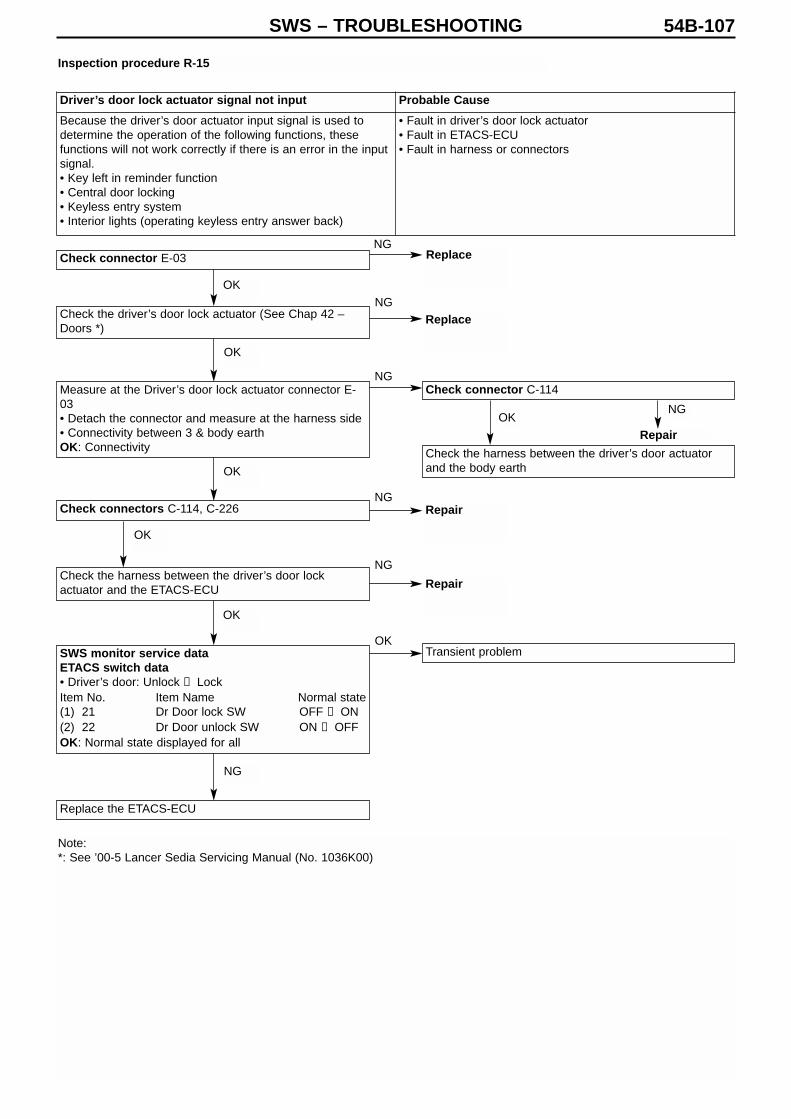
SWS – TROUBLESHOOTING 54B-107
Check connector E-03
Check the driver’s door lock actuator (See Chap 42 –Doors *)
Check connectors C-114, C-226
Check the harness between the driver’s door lockactuator and the ETACS-ECU
Measure at the Driver’s door lock actuator connector E-03• Detach the connector and measure at the harness side• Connectivity between 3 & body earthOK: Connectivity
SWS monitor service dataETACS switch data• Driver’s door: Unlock → LockItem No. Item Name Normal state(1) 21 Dr Door lock SW OFF → ON(2) 22 Dr Door unlock SW ON → OFFOK: Normal state displayed for all
Replace the ETACS-ECU
Check connector C-114
Check the harness between the driver’s door actuatorand the body earth
Transient problem
Inspection procedure R-15
Note: *: See ’00-5 Lancer Sedia Servicing Manual (No. 1036K00)
Driver’s door lock actuator signal not input Probable Cause
Because the driver’s door actuator input signal is used todetermine the operation of the following functions, thesefunctions will not work correctly if there is an error in the inputsignal.• Key left in reminder function• Central door locking• Keyless entry system• Interior lights (operating keyless entry answer back)
• Fault in driver’s door lock actuator• Fault in ETACS-ECU • Fault in harness or connectors
OK
NG
NG
NG
NG
OKNG
NG
OK
OK
OK
OK
OK
NG
Repair
Replace
Replace
Repair
Repair

SWS – TROUBLESHOOTING54B-108
Inspection procedure R-16
Is the speedometer working normally?
Check connectors B-131, B-31, C-22
Confirm the trouble symptoms
Check the harness between the vehicle speed sensorand the ETACS-ECU
Replace the ETACS-ECU
Carry out speedometer troubleshooting (See Chap. 54ACombination meter *)
Note: (1) The vehicle speed senor signal input is checked during actual travel of the vehicle.(2) *: See ’00-5 Lancer Sedia Servicing Manual (No. 1036K00)
Vehicle speed signal not input Probable Cause
Because the vehicle speed signal is used to determine theoperation of the following functions, these functions will notwork correctly if there is an error in the input signal.• Windscreen wipers/washers (speed sensitive wiper function)• Motorised retractable door mirrors (automatic return
function)
• Fault in vehicle speed sensor• Fault in ETACS-ECU • Fault in harness or connectors
NO
YES
NG
NG
OK
NG
OK
Repair
Repair

SWS – TROUBLESHOOTING 54B-109
Inspection procedure R-17
SWS monitor keyless entry reception checkCheck using all keyless entry transmitters with whichproblems were confirmed• Keyless entry transmitterLock switch: ONMUT display Normal stateLock • Keyless entry transmitterUnlock switch: Long pressMUT display Normal stateUnlock OK: All display normal state
Replace the keyless entry transmitter
Replace the transmitter
Register encryptedcodes
Confirm the troublesymptoms
End oftroubleshooting
Replace
Replace the ETACS-ECU
Check the battery ofthe keyless entrytransmitter
Keyless entrytransmitter check(1) Register keyless entry
transmitters that arefunctioning normally.(The keyless entrytransmitter installationscrews are colouredsilver.)
(2) Check that the inputsignals are inputcorrectly when therespective switches ofthe transmitter arepressed.OK: Signals inputcorrectly
Confirm the troublesymptoms
Replace the ETACS-ECU
Transient problem
Various switch signals of keyless entry transmitter not input Probable Cause
The keyless entry transmitter input signal is used to determine theoperation of the keyless entry system, and if there is a problem withthis signal, then the keyless entry system will not work correctly.
• Fault in keyless entry transmitter• Fault in keyless entry transmitter battery• Fault in ETACS-ECU
Display normal for all
Normal state displayedfor some only
“X” displayedfor all
OK
NG
OK
OK
NGNG
NG
OK

SWS – TROUBLESHOOTING54B-110
Inspection procedure R-18
Check connector C-129
Check the fog light switch (See Chap 54A – Fog lights *)
Check connectors C-225, C-110
Check the harness between the fog light switch and theETACS-ECU
Transient problem
Check connector C-107
Check the harness between the fog light switch and thebody earth, and repair
Replace the ETACS-ECU
Measure at the Fog light switch connector C-129• Detach the connector and measure at the harness side• Ignition switch: ON• Connectivity between 2 & body earthOK: Connectivity
SWS monitor service dataETACS switch data• Fog light switch: ONItem No. Item Name Normal state10 F Fog light SW ONOK: Normal state displayed
Note: *: See ’00-5 Lancer Sedia Servicing Manual (No. 1036K00)
Fog light switch signal not input Probable Cause
The fog light switch input signal is used to determine theoperation of the fog lights, so any problem in this signal willprevent the fog lights from lighting up.
• Fault in fog light switch• Fault in ETACS-ECU • Fault in harness or connectors
OK
OK
OK
OK
OK
OK
NG
NG
NG
NGOK
NG
NG
NG
Repair
Repair
Repair
Repair
Replace

SWS – TROUBLESHOOTING 54B-111
Check connector C-224
Check connector C-210
Check the harness between the ETACS-ECU and theignition switch (ACC), and repair
Check connectors C-211, C-32
Check the harness between the ETACS-ECU and thebattery, and repair.
Check connector C-210
Check the harness between the ETACS-ECU and theignition switch (IG1), and repair
Confirm the trouble symptoms
Replace the ETACS-ECU
Transient problem
Measure at the ETACS-ECU C-224• Detach the connector and measure at the junction box
side• Ignition switch: ON(1) Voltage between 20 & body earth
OK: Battery voltage(2) Voltage between 8 & body earth
OK: Battery voltage(3) Voltage between 4 & body earth
OK: Battery voltage(4) Voltage between 18 & body earth
OK: Battery voltage
Inspection procedure R-19
Generic fuse No.17 load use signal not detected Probable Cause
The generic fuse No.17 load signal is used to determine theinterior light cut-off function, and if there is a problem in thissignal, then the following functions will cease to work properly.• Ignition key cylinder illumination light• Interior light
• Fault in ETACS-ECU • Fault in harness or connectors
OK
(3), (4) NG
OKNG
Repair
NG
(1) NG
(2) NG
OK
OK NG
NGOK
OK NG
Repair
Repair
Repair

SWS – TROUBLESHOOTING54B-112
11. Chart of terminal voltages
11-1 ETACS-ECU
Note :Terminals No. 1 to 20 cannot be measured as the ETACS-ECU is installed directly on the junction box, and they are listed forreference.
TerminalNo.
Check Item Check Conditions Normal State
1 Electric window relay output Electric windows operable Battery voltage2 Central door lock power supply (battery
voltage)Any Battery voltage
3 Earth (for ECU) Any 0V4 Ignition switch (ACC) Ignition switch : ACC Battery voltage5 Interior light output Interior lights switched on 2V or lower6 Interior light power supply (battery
voltage)Any (Interior light cut-off function notoperating)
Battery voltage
7 All door switch input Any door switch : ON (door open) 0V8 Ignition switch (IG1) power supply Ignition switch : ON Battery voltage9 RH Turn indicator light output RH Turn indicator light on Battery voltage10 Driver’s door switch input Driver’s door switch : ON (door open) 0V11 Hazard light power supply (battery
voltage)Any Battery voltage
12 Central door locking (lock) output Door lock actuator operating (lockoperation)
Battery voltage
13 Central door locking (unlock) output(except driver’s)
Door lock actuator operating (unlockoperation)
Battery voltage
14 LH Turn indicator light output LH Turn indicator light on Battery voltage1516 Rear wiper output Rear wiper operating Battery voltage17 Rear wiper automatic stop signal input Rear wiper operating Battery voltage18 Ignition switch (ACC) power supply Ignition switch : ACC Battery voltage1920 Battery voltage (for ECU) Any Battery voltage2122 Central door locking (unlock) output (for
driver’s door)(Vehicle fitted with keyless entry)
Door lock actuator operating (unlockoperation)
Battery voltage
23 Rear washer output Rear washer operating Battery voltage24 Motorised remote control mirror switch
(fold / return switch) inputMotorised remote control mirrorswitch (fold / return) switch : ON
0V
25 – 2930 Key reminder switch input Key reminder switch : ON
(Ignition key removed)0V
31 Motorised foldable door mirror output Motorised foldable door mirrorsoperating (fold operation)
Battery voltage
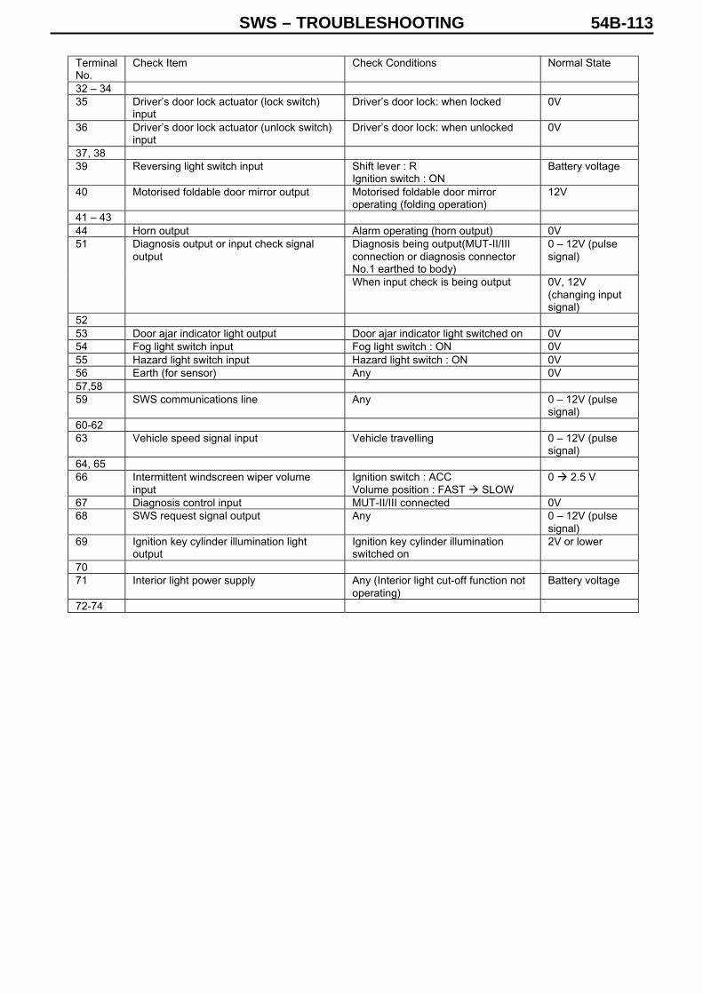
SWS – TROUBLESHOOTING 54B-113
TerminalNo.
Check Item Check Conditions Normal State
32 – 3435 Driver’s door lock actuator (lock switch)
inputDriver’s door lock: when locked 0V
36 Driver’s door lock actuator (unlock switch)input
Driver’s door lock: when unlocked 0V
37, 3839 Reversing light switch input Shift lever : R
Ignition switch : ONBattery voltage
40 Motorised foldable door mirror output Motorised foldable door mirroroperating (folding operation)
12V
41 – 4344 Horn output Alarm operating (horn output) 0V
Diagnosis being output(MUT-II/IIIconnection or diagnosis connectorNo.1 earthed to body)
0 – 12V (pulsesignal)
51 Diagnosis output or input check signaloutput
When input check is being output 0V, 12V(changing inputsignal)
5253 Door ajar indicator light output Door ajar indicator light switched on 0V54 Fog light switch input Fog light switch : ON 0V55 Hazard light switch input Hazard light switch : ON 0V56 Earth (for sensor) Any 0V57,5859 SWS communications line Any 0 – 12V (pulse
signal)60-6263 Vehicle speed signal input Vehicle travelling 0 – 12V (pulse
signal)64, 6566 Intermittent windscreen wiper volume
inputIgnition switch : ACCVolume position : FAST SLOW
0 2.5 V
67 Diagnosis control input MUT-II/III connected 0V68 SWS request signal output Any 0 – 12V (pulse
signal)69 Ignition key cylinder illumination light
outputIgnition key cylinder illuminationswitched on
2V or lower
7071 Interior light power supply Any (Interior light cut-off function not
operating)Battery voltage
72-74

SWS – TROUBLESHOOTING54B-114
11-2 Column switch
11-3 Front ECU
Note : The front ECU is installed directly on the relay box, and cannot be measured. The terminals are listed here forreference.
TerminalNo.
Check Item Check Conditions Normal State
1 Battery power supply Any Battery voltage2 SWS request signal input Any 0 – 12 V (pulse
signal)3 SWS communications line Any 0 – 12 V (pulse
signal)4 Earth Any 0V56 Intermittent windscreen wiper volume
outputIgnition switch : ACCVolume position : FAST SLOW
0 2.5V
78 Windscreen wiper switch back-up output Low speed windscreen wiper or High
speed windscreen wiper : ON0V
9 Ignition switch (IG1) power supply Ignition switch : ON Battery voltage10 Head light switch back-up output Head light switch : ON 0V
TerminalNo.
Check Item Check Conditions Normal State
1 Fog light output Fog lights switched on2 Head light (high beam) output Head lights (high beam) switched on Battery voltage3, 4 Battery power supply (for head light) Any Battery voltage5 Battery power supply (for tail light) Any Battery voltage6 Head light (low beam) output Head lights (low beam) switched on Battery voltage7 Battery power supply (for ECU) Any Battery voltage8 Tail light output Tail lights switched on Battery voltage9 – 1121 Windscreen washer output Windscreen washer operating Battery voltage22 SWS communications line Any 0 – 12V (pulse
signal)23 Windscreen wiper automatic stop signal
inputWindscreen wiper operating Battery voltage
24 Ignition switch (ACC) power supply Ignition switch : ACC Battery voltage25 Head light switch back-up input Head light switch : ON 0V26 Windscreen wiper switch back-up input Low-speed windscreen wiper switch
or high-speed windscreen wiperswitch : ON
0V
27 Windscreen wiper (LO speed) output Windscreen wiper operating(Low speed operation)
Battery voltage
28 Windscreen wiper (HI speed) output Windscreen wiper operating(High speed operation)
Battery voltage
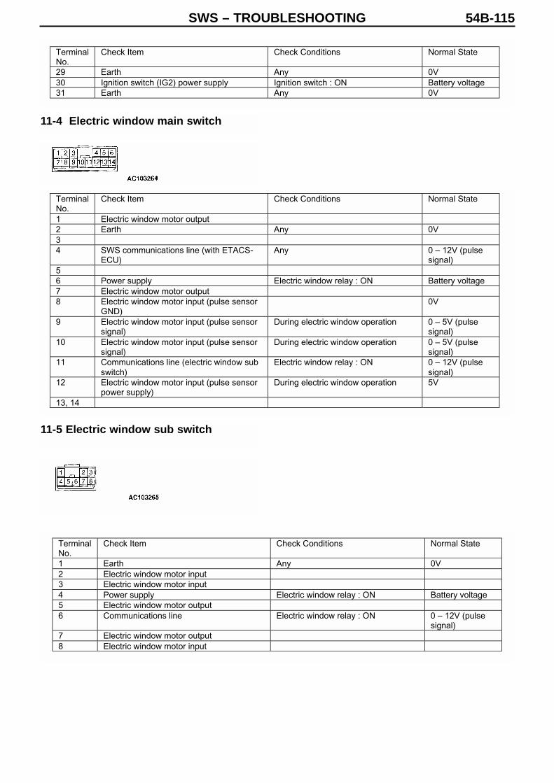
SWS – TROUBLESHOOTING 54B-115
11-4 Electric window main switch
11-5 Electric window sub switch
TerminalNo.
Check Item Check Conditions Normal State
29 Earth Any 0V30 Ignition switch (IG2) power supply Ignition switch : ON Battery voltage31 Earth Any 0V
TerminalNo.
Check Item Check Conditions Normal State
1 Electric window motor output2 Earth Any 0V34 SWS communications line (with ETACS-
ECU)Any 0 – 12V (pulse
signal)56 Power supply Electric window relay : ON Battery voltage7 Electric window motor output8 Electric window motor input (pulse sensor
GND)0V
9 Electric window motor input (pulse sensorsignal)
During electric window operation 0 – 5V (pulsesignal)
10 Electric window motor input (pulse sensorsignal)
During electric window operation 0 – 5V (pulsesignal)
11 Communications line (electric window subswitch)
Electric window relay : ON 0 – 12V (pulsesignal)
12 Electric window motor input (pulse sensorpower supply)
During electric window operation 5V
13, 14
TerminalNo.
Check Item Check Conditions Normal State
1 Earth Any 0V2 Electric window motor input3 Electric window motor input4 Power supply Electric window relay : ON Battery voltage5 Electric window motor output6 Communications line Electric window relay : ON 0 – 12V (pulse
signal)7 Electric window motor output8 Electric window motor input

SWS – TROUBLESHOOTING54B-116
11-6 Sunroof motor assembly
TerminalNo.
Check Item Check Conditions Normal State
1 Battery voltage (for motor) Any Battery voltage2 Ignition switch (IG2) power supply Ignition switch : ON Battery voltage3, 45 Earth Any 0V6 Sunroof switch (close / open) input Sunroof switch : Close / Open 0V7 Sunroof switch (up) input Sunroof switch : Up 0V8 Sunroof switch (open) input Sunroof switch : Open 0V910 SWS communications line Any 0 – 12V (pulse
signal)

SWS – ON VEHICLE SERVICING 54B-117
On Vehicle Servicing
Adjustment function (User Mode)
By setting the various switches to match the conditions for entering adjustmentmode, you can switch the security alarm function on and off, or adjust thewarning output. Any adjustments made are saved, even when the battery isdisconnected.
1. Entering adjustment mode(1) Set the following switches as indicated.
• Driver’s door switch: ON (driver’s door open)• Key reminder switch: ON (ignition key removed)• Lighting switch: OFF(2) If the windscreen washer switch is switched on continuously for 10seconds or more (by pulling the wiper lever towards you), then the ETACS-ECU buzzer will sound once, and the system will enter adjustment mode. Inthis state (and keeping the wiper lever pulled towards you) the setting can bechanged each time you press the unlock switch on the transmitter.
2. Adjusting the security alarm functionsYou can switch the security alarm function on and off, and change the alarmtime, in the following sequence. (After option c, the sequence starts again froma.)
a. Security alarm function OFF. (Initial state): Buzzer sounds once.b. Security alarm function ON. (Hazard and horn used for alarm): Buzzersounds 3 times.c. Security alarm function ON. (Horn only used for alarm): Buzzer sounds 5times.
3. Cancelling adjustment modeThe adjustment mode is cancelled when any one of the following conditionsis met.• Driver’s door switch: OFF (Driver’s door closed)• Key reminder switch: OFF (ignition key inserted)• Lighting switch: ON• Windscreen washer switch: OFF• If 30 seconds have elapsed without the unlock switch being pressed.
Note 1. Although the wiper washer switch and transmitter are operated during
adjustment mode, the wiper/washer and keyless entry system are notactivated by these operations.
2. This adjustment function is also described in the Owner’s Manual, so thatusers are able to perform the adjustment procedure themselves.
3. The user’s wishes should be confirmed fully before setting up this function.(Where possible, get users to set up the function themselves, so that theyunderstand how it works.)

SWS – ON VEHICLE SERVICING54B-118
Adjustment function (Dealer mode)
The following functions can be adjusted from the MUT-II/III. Any adjustmentsmade will be saved, even if the battery is disconnected.
• Door ajar warning.If any one of the doors, including the boot, is open whilst the vehicle istravelling, then this function warns the driver that a door is open by sounding abuzzer and causing a door ajar indicator light to flash on the combinationmeter..
• Turn indicator buzzerThis function causes a buzzer to sound in synchronization with the hazardlights and turn indicator lights.
• Keyless entry system hazard light answer back functionThis function allows the driver to confirm a lock/unlock operation, even whenhe or she is away from the car. The hazard lights flash when a lock or unlockoperation is performed by the keyless entry transmitter.
• Operation of electric window and sunroof by multi-mode keyless entry systemThis function causes the electric window and sunroof to close when thekeyless entry transmitter is operated, even when the driver is away from thecar.
• Timer lock delay after keyless entry unlockIf any door, including the boot, is not opened after the doors have beenunlocked by operation of the keyless entry transmitter, then after a prescribedtime delay, the doors are automatically locked again.
• Electric window and sunroof timer function.This function allows the electric window and sunroof to be operated for aprescribed time, even after the ignition switch has been set to the LOCK (OFF)position.
• Electric window lock driver operationThis function allows electric windows other than the driver’s window to beoperated by the electric window main switch, when the electric window lockswitch built into the electric window main switch has been pressed.
• Vehicle speed sensitive wiper functionThis function changes the intermittent wiper period in accordance with theintermittent wiper adjustment knob and the vehicle speed, when thewindscreen wiper switch is set to the intermittent position.
• Rear wiper intermittent periodWhen the rear wiper switch is on, the rear wipers work intermittently. Thisfunction sets the rear wiper to continuous operation, when the rear wiperswitch is operated continuously.
• Automatic return function for motorised retractable door mirror This function opens the door mirrors automatically if the vehicle is travellingwith the door mirrors retracted. Other methods can also be used to perform theretract / return operation of the door mirrors.
• Head light automatic cut-off functionThis function automatically turns off the head lights if the driver’s door isopened when the lighting switch is set to the TAIL, AUTO, or HEAD position,and the ignition switch is set to LOCK (OFF).
• Interior light delayed switch off periodThis function causes the interior lights to switch off automatically after aprescribed delay, when the door has been closed with the ignition switch in theLOCK (OFF) position.

SWS – ON VEHICLE SERVICING 54B-119
• Interior light automatic cut-off functionThis function automatically switches off the interior lights after a specified timedelay if they have been left on with the ignition switch in the LOCK (OFF)position.
• Security alarmSwitches the security alarm function on and off.
• Adjustment during electric window key off timerThis function allows electric windows other than the driver’s window to beoperated during operation of the electric window timer.
• Initialise all functions (return to initial settings)This function returns all the adjusted functions to their original factory settings.
ItemNo.
MUT itemdisplay
Item MUT adjustment display Details of adjustment
Function ON (A) Function ON: The tail lightsare automatically switched off,if turned on when the ignitionswitch is at the LOCK (OFF)position.
Function ON (D) Function ON: The tail lightsare not automatically switchedoff, if turned on when theignition switch is at the LOCK(OFF) position. (Initial setting)
2 HD auto cut-off Head lightautomatic cut-offfunction
Function OFF Function OFFFunction ON Function ON (initial setting)4 Speed
sensitive wiperVehicle speedsensitive wiperfunction Function OFF Function OFF
Speed sensitivefunction ON
Vehicle speed sensitivedeployment (initial setting)
IG operated functionON
Linked to ignition
Keyless operatedfunction ON
Linked to keyless entry
5 Door mirror Motorisedretractable doormirror: automaticreturn function
Function OFF No functionLock operated Sounds at each lock operationLock operated twice Sounds when lock is operated
twice consecutively (within 1second)
6*1 Keyless (horn) Keyless entryhorn answerback
Function OFF Function OFFNormal Operates according to keyless
entry horn answerbackadjustment function setting
8*1 Keyless (horn)night time
Keyless entryhornanswerback:night timedisabling
Night time operationdisabled
Operates according to keylessentry horn answerbackadjustment function setting,but horn sound disabledduring night time
Light up on lock, unlock Function ON for both lock andunlock (initial setting)
Light up on lock only Function ON for lock onlyLight up on unlock only Function ON for unlock only
9 Keyless(hazard)
Keyless entrysystem: hazardanswer backfunction
Function OFF Function OFF

SWS – ON VEHICLE SERVICING54B-120
ItemNo.
MUT itemdisplay
Item MUT adjustment display Details of adjustment
Open and close Both close and openoperations (open operation forwindows only)
Close only Close operation only (initialsetting)
10 Keyless (P/W) Multi-modekeyless entrysystem: Electricwindow andsunroof operation
Function OFF Function OFF
Horn and hazard Function ON: Horn & HazardHazard only Function ON: Hazard only
11 Security alarm Security alarm
Function OFF Function OFF (initial setting)Function ON Function ON15 Turn indicator
buzzerTurn indicatorlight operatingsound function Function OFF Function OFF (initial setting)
60 s 60 s30 s 30 s15 s 15 s7.5 s 7.5 s
16 Interior lightresponse time
Interior lightdelayed switchoff time
NO delayed switch off 0 s (no delay operation)Timer function OFF Timer function OFF30 s 30 s (initial setting)3 min. 3 min.
18 Key off timerperiod
Electric window& sunroof timerfunction period
10 min. 10 min.Normal operation Accepts normal operation
during timer period (initialsetting)
19 P/W key offtimer
Operationaladjustmentduring electricwindow key offtimer *2
Main S/W operationprohibited
Prohibits operation of electricwindows (except driver’s) fromelectric window main switch,during timer period
30 s 30 s (initial setting)60 s 1 min.120 s 2 min.
24 Keyless timerlock T
Timer lock timeafter keylessentry unlock
180 s 3 min.Function ON Function ON (initial setting)26 Door ajar
buzzerDoor ajarwarning function Function OFF Function OFF
8 s 8 s: No continuous operation(initial setting)
4 s (continuous ON) 4 s (continuous ON)8 s (continuous ON) 8 s (continuous ON)16 s (continuous ON) 16 s (continuous ON)
28 Rear wiper INTperiod
Rear wiperintermittentperiod
Continuous operation Continuous operation (nointermittent operation)
3 min. Automatic cut-off ON: 3 min.30 min. Automatic cut-off ON: 30 min.
(initial setting)60 min. Automatic cut-off ON: 60 min.
30 Interior lightauto cut-off
Interior lightautomatic cut-offfunction
Function OFF Automatic cut-off OFFAll seat operation ON Operation possible from all
seats when locked (initialsetting)
31 P/W lock mode Electric windowlock driveroperation
Only driver’s seatoperation
Operation prohibited fromseats other than driver’s,when locked
SWS – ON VEHICLE SERVICING 54B-121
Note
1. *1 optional: Can only be adjusted when the smart entry system is fitted. Afterfitting the smart entry system, a list of adjustable functions will be displayedwhen the entry system is operated for the first time. If all the functions areinitialised, then the adjusted items will be deleted, but by activating the smartentry system, the list of adjusted functions will be displayed again.
2. *2 This adjustment item restricts the operation of the electric window timerfunction, and is used when performing Inspection procedure D-8 “Electricwindow comes down automatically”.
Initialising all functions (Returning to initial settings)This function allows all of the adjusted functions to be returned to the originalfactory settings.
RJSY301024-352