Section 5: Intersections and Crossings
48
TOOLBOX SECTION Intersecons and Crossings 5
Transcript of Section 5: Intersections and Crossings
TOOLBOX SECTION
Intersections and Crossings
5
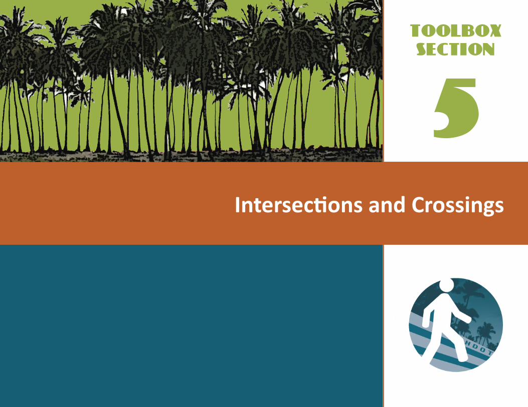
Hawaii's beautiful weather encourages pedestrian activity.

IN THIS SECTION
5-1
Intersections and Crossings
Pedestrians at a marked crosswalk
•DESIGNPRACTICESATINTERSECTIONS
•MINIMIZINGCROSSINGDISTANCES
•MID-BLOCKCROSSINGS
•MINIMIZINGPEDESTRIAN/ MOTORVEHICLECONFLICTSATINTERSECTIONSANDCROSSINGS
•OTHERINNOVATIVETECHNOLOGIES
•EFFECTSOFPEDESTRIANIMPROVEMENTSONVEHICLECAPACITY
•OTHERRESOURCES
INTERSECTIONS AND CROSSINGS
Intersections and crossings occur wherever the
pedestrian network intersects the roadway
network. Pedestrians are extremely vulnerable
at these locations because they move so slowly
relative to vehicles, and they weigh so much less
than vehicles. For these reasons pedestrian
safety should be a high priority when designing
or retrofitting intersections and crossings.
Since pedestrians are actually in the roadway/
street at intersections and crossings, many of
the recommendations below involve roadway
design specifically, including markings, signs,
signalization, and geometry. All designers,
including roadway and traffic engineers, urban
designers, landscape architects, and others
should actively use the guidance in this toolbox
section to enhance pedestrian safety.
Design Practices at IntersectionsIntersection design requires consideration
of all potential users, especially pedestrians
who are the most vulnerable while crossing.
Design solutions need to protect the safety
of pedestrians, while also improving their
accessibility and mobility. At the same time,
design solutions still need to meet the needs of
motorists and bicyclists. Carefully implemented
engineering studies can help determine the best
solutions for each location on a case-by-case
basis. Sometimes what is the best design solution
for pedestrians does not work well for bicycles
and/or vehicles and vice versa. The needs of all
intersection users must be considered.

Intersections and Crossings
5-2
Commonly used crossing improvements
include: crosswalks, curb ramps, pavement
markings, pedestrian refuges, signalization,
signage, and lighting. Exhibit 5.1 lists some
basic principles of intersection design related
to the needs of pedestrians.
DETERMINING THE NEED FOR CROSSING
IMPROVEMENTS AT INTERSECTIONS
Intersections can be made more pedestrian-
friendly by implementing designs that improve
crossing conditions, reduce crossing distances,
and minimize conflicts between pedestrians,
bicycles, and motor vehicles. In all cases,
the crossing treatment should be guided by
engineering analysis that clearly determines
the needs and provides recommendations for
the improvement of pedestrian facilities. Each
location should be studied on a case-by-case
basis. Special conditions (such as land use,
school routes, pedestrians with special needs,
etc.) may exist that need to be addressed with
pedestrian facilities.
CrosswalkMarkingsMarked crosswalks alert motorists to the
potential of pedestrians crossing and define the
area where pedestrians have the right-of-way. At
stop-controlled or signalized intersections, the
preferred marking, and the Hawaii Department
of Transportation (HDOT) standard is the ladder
style crosswalk.
On multi-lane roads with an ADT of 12,000
or more, marked crosswalks should always
be combined with other pedestrian safety
measures, such as stop or yield signs,
signalization, or raised medians (see sidebar
on page 5-3).
CROSSWALK DIMENSIONS
The HDOT standards require that crosswalks
be a minimum of 10 ft (3.0 m) wide and at least
as wide as the approaching sidewalk. In high
pedestrian areas, crosswalks can be up to 20 ft
(6.1 m). The approaching sidewalk and corner
area at the intersection needs to be free of
obstructions so that pedestrians can freely travel
in either direction to cross the street. Exhibit
5.2 shows typical crosswalk markings at an
intersection.Exhibit 5.3 shows typical crosswalk
dimensions. The HDOT standards call for the
width of the ladder bars to be 12 in (30.5 cm)
with 18 in (45.7 cm) spacing.
EXHIBIT5.1BasicPrinciplesofIntersectionDesigntoAccommodatePedestrians
Design compact intersections.
Eliminate unrestricted motor vehicle movements.
Reduce motor vehicle speeds through intersections.
Create crossings on all legs of an intersection.
Design crossing in a direct line, at 90 degrees to the direction of vehicular travel, as feasible.
Clearly identify crossings to all pedestrians, including those with sight impairments.
Avoid multiple and skewed intersections.

5-3
Intersections and Crossings
TheFederalHighwayAdministration’s2005study,"SafetyEffectsofMarkedversusUnmarkedCrosswalksatUncontrolledLocations",evaluatedpedestriancrashesat1,000markedcrosswalksand1,000matchedbutunmarkedcomparisonsites.Noneofthesitesinthestudyhadtrafficsignalsorstopsignsontheapproachtothecrosswalk.Theresultsofthestudyindicated:
ON TWO-LANE ROADS• Therewasnodifferenceincrashratesbasedonthepresenceorabsenceofamarkedcrosswalk.
ON MULTI-LANE ROADS•OnroadswithanADTof12,000ormore,thepresenceofamarkedcrosswalkalone,withoutanyotherimprovementstopedestriansafety,wasassociatedwithahigherrateofcrashes.(Meaning:additionalimprovementssuchasadvanceandoverheadsigns,refugeislands,etc.areneededattheselocations.)
• Raisedmediansandrefugeislandsareassociatedwithasignificantlylowerrateofpedestriancrasheswithbothmarkedandunmarkedcrosswalks.
• Paintedmediansdonotsignificantlyimprovepedestriansafetyatcrossings,comparedtomultilaneroadswithnomedianatall.
•Olderpedestrianshavehighercrashratesrelativetotheirexposurethanotheragegroups.
MARKING CROSSWALKS
Ladder bar markings are highly visible and clearly mark pedestrian crossings.
Create crossings on all legs of an intersection.
Crossings should be at right angles to the
intersection, as feasible.
EXHIBIT5.2TypicalCrosswalkMarkings

Intersections and Crossings
5-4
Crosswalks that lead to public amenities
such as a park, beach, or civic building can
be considerably wider than ten feet and can
be enhanced with special markings or paving
treatments (see below for types of markings).
TYPES OF CROSSWALK MARKINGS
Markings at crosswalks include striping patterns,
stop bars, advance stop bars and yield signs,
and sometimes other features. The ladder bar
crosswalk marking pattern is the most frequently
used because it is highly visible to pedestrians
and motorists and can be spaced to avoid tire
friction, thus reducing maintenance costs.
STOP BARS, ADVANCE STOP BARS
Stop bars are typically placed at intersections
(where motorists are required to stop) to
prevent overhang into crosswalk areas. Stop bars
are normally 12 to 24 in wide (30.5 to 61.0 cm)
white stripes that extend across all approach
lanes. They should be located at least 4 ft (1.2
EXHIBIT5.3CrosswalkDimensions
18"(457 mm)
10' min(3 m)
Width of stripe: 12” (30 mm)
LADDER BAR DIMENSIONS (HDOT STANDARD)
Align markings to avoid vehicle wheel paths.
m) in advance of the crosswalk, and parallel to
it. The HDOT standard is a 12 in (30.5 cm) wide
white line, a minimum of 4 ft (1.2 m) in advance
of the crosswalk. Where there are heavy truck
volumes, the stop bar should be set farther back
in the receiving street so that large vehicles have
ample room to complete their turn. Stop bars
ADVANCE STOP BARS
Theadvancestopbarincreasesthetimeforavehicletoentertheintersectionongreen,andmayresultinamodestreductioninintersectioncapacity.However,advancestopbarsmaybeofbenefitinreducingthefrequencyofcrashesfromred-lightrunning.
4' (1.2 m) min30' (9.1) preferredcheck standards
based on roadway classification

5-5
Intersections and Crossings
Pedestrians use crosswalks in a variety of ways. (Source: A parrot talks in Chocolate.com)
Wide crossings with no markings create uncomfortable places for pedestrians.
A
Driver in Car A can see pedestrian and has time to stop at the Advance Stop Bar.
Pedestrian can see Car A and choose not to cross.
Advance Stop Bar
“Stop Here for Pedestrians”sign
CarA
EXHIBIT5.4Anadvancestopbargivesbothpedestriansandmotoristsbettervisibility.
30’ (
9.1
m) t
o 50
’ (15
.2 m
) pre
ferr
ed4'
(1.2
m) m
in
can be installed at an angle for this purpose.
Stop bars should also be used for right-turn-
on-red movements and for vehicles turning left
from the cross street.
On multiple lane roadways at uncontrolled
approaches, advance stop lines increase the
safety of pedestrians by reducing the screening
effect of vehicles in the right lane. Advance
stop bars should be used with a “Stop Here for
Pedestrians” sign. (See Exhibit 5.4.)
RUMBLE STRIPS
Rumble strips with raised or recessed pavement
treatments are sometimes placed in advance of
crosswalks in rows, which create a “rumbling”
effect alerting approaching drivers of the
upcoming crosswalk. These types of markers
should only be used if they can be placed far
enough in advance of the crosswalk to be an
effective warning device (at the same location
as the crosswalk advance warning sign). Raised
pavement markers must be placed outside the
required clearance area of bike lanes and should
only be installed after an engineering study
determines they are appropriate. In addition, care
should be taken in the use of rumble strips as they
5-6
Intersections and Crossings
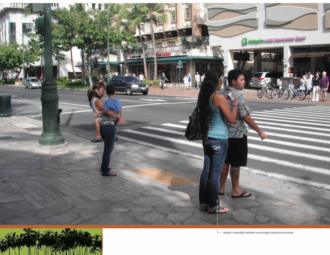
Crosswalk markings clarify the space used by pedestrians.
can cause higher noise levels which could affect
nearby residents. They may be more suitable for
gateways where frontage property is limited.
CROSSWALK MARKING MATERIALS
AND MAINTENANCE
Crosswalk marking materials include inlay tape,
thermoplastic, and paint. Exhibit 5.5 summarizes
the qualities of each. Specific design details
related to pavement striping and marking
techniques can be found in the 2009 Manual on
Uniform Traffic Control Devices (MUTCD). Other
materials such as concrete, unit pavers, painted
stencil patterns, and stamped asphalt may be
used, but refer to the MUTCD for requirements
related to contrast.
Markings should be monitored regularly,
maintained in good condition, and should be
removed when no longer needed.
CurbRampsCurb ramps are often considered to be the
most important elements of an accessible
pedestrian environment because they provide
accessibility at the grade transition from the
sidewalk to the street. They facilitate crossing
EXHIBIT5.5CrosswalkMarkingMaterials
INLAY TAPE Highly visible, not slippery, requires expertise to install correctly; recommended for new and resurfaced pavement; more cost-effective than paint in the long run
THERMOPLASTIC Highly visible, not slippery, may be a better option than tape on rough surfaces
PAINT Low initial cost, but slippery and not as visible as tape or thermoplastic; requires frequent repainting
Source: Pedestrian and Bicycle Information Center (PBIC), Crossing Enhancements
Painted markings can deteriorate quickly. Regular inspection and maintenance contribute to pedestrian safety.
for wheelchair users, people pushing strollers,
bicyclists, and others. When properly located,
they can also help direct pedestrians, including
people who are blind or have low vision, toward
the crosswalk. Toolbox Section 3—Accessibility
discusses placement and design of curb ramps.
SignalizationDETERMINING THE NEED FOR
PEDESTRIAN SIGNALS
Pedestrian signals should be installed
wherever there is a traffic signal, except where
5-7
Intersections and Crossings
pedestrians are prohibited such as on certain
highways, as recommended by the Pedestrian
and Bicycle Information Center (PBIC). Major
factors in pedestrian signalization design include
signal timing, types of signals, and placement
and design of both signals and pedestrian
actuators. Signalization should be designed
in accordance with an engineering study. The
MUTCD provides guidelines for determining
warrants for signalization based on:
1. Vehicular traffic alone
2. A combination of pedestrian and
vehicular traffic
3. School zone pedestrian and vehicular traffic
4. Crash experience
See the 2009 MUTCD Section 4C for more
information.
The revised minimum pedestrian volume
warrant in the MUTCD states that a traffic signal
may be warranted when the pedestrian volume
crossing the major street at an intersection
or mid-block location during an average day
is either (1) 100 or more for each of any four
hours or (2) 190 or more during any one hour.
These volume requirements may be reduced by
as much as 50 percent when the predominant
crossing speed is below 4 feet per second/fps
(1.2 meters per second/mps). A traffic signal
may not be needed, however, if adjacent traffic
signals consistently provide gaps of adequate
length for pedestrians to cross the street at least
every minute.
It should be noted that these are guidelines.
Engineering analysis should be conducted on a
case-by-case basis to determine the need for
traffic and pedestrian signals. The analysis may
consider special factors, including proximity of
the intersection to school zones, as well as areas
where pedestrians with special needs may use
the intersection (such as near senior centers,
hospitals, etc.). The best practice is to consider
the needs of pedestrians, along with all other
intersection users, in the analysis process.
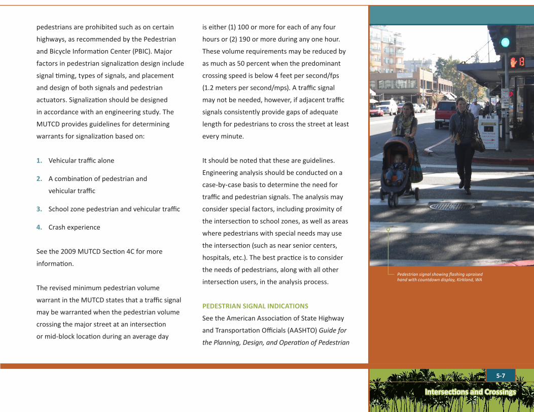
PEDESTRIAN SIGNAL INDICATIONS
See the American Association of State Highway
and Transportation Officials (AASHTO) Guide for
the Planning, Design, and Operation of Pedestrian
Pedestrian signal showing flashing upraised hand with countdown display, Kirkland, WA
5-8
Intersections and Crossings
Facilities for locations where pedestrian signal
indications should be provided at traffic signals.
Provide pedestrian signal indications where:
1. Traffic signals are installed based on meeting
the minimum pedestrian volume or school
crossing warrants (see MUTCD warrants).
2. Pedestrian pushbuttons are in use.
3. A protected signal phase is provided for
pedestrian movements in one or more
directions at a signalized intersection, with
all conflicting vehicular traffic being stopped.
4. No vehicular indications are visible to
pedestrians either starting or continuing
their crossing (such as at intersections with
pedestrian refuge or crossing islands).
5. The vehicular indications that are visible to
pedestrians provide insufficient guidance for
them to decide when it is safe to cross, such
as at one-way roadways, T-intersections, or
multiphase signal operations.
6. An established school crossing is located at a
signalized intersection.
7. Engineering judgment determines that
pedestrian signal heads would minimize
vehicle-pedestrian conflicts.
8. Most of the other signalized intersections are
already equipped with pedestrian signals.
9. Significant numbers of older adults or
school-age children are present.
10. Wide streets where providing pedestrian
clearance is important and moderate to high
numbers of crossings occur.
11. Pedestrians request signal heads on the basis
of program accessibility at locations where an
engineering study confirms that installations
of pedestrian signal heads is appropriate.
The above guidance applies to existing
intersections with traffic signals. When new
intersections are constructed or when existing
intersections are reconstructed, intersections must
be designed to meet accessibility requirements,
including the provision of accessible pedestrian
signals. Refer to Toolbox Section 3—Accessibility
for more information. Also refer to the Guide for
the Planning, Design, and Operation of Pedestrian
Facilities for more information including
innovative pedestrian indication options.
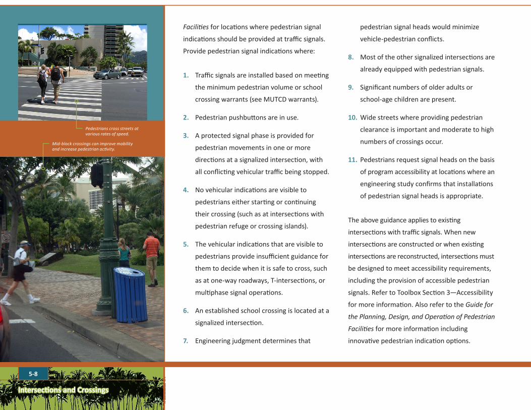
Pedestrians cross streets at various rates of speed.
Mid-block crossings can improve mobility and increase pedestrian activity.
Intersections and Crossings
5-9
C R O S S I N G D I S T A N C E
A V E R A G E P E D E S T R I A N
C R O S S I N G T I M E *
O L D E R A D U L T C R O S S I N G
T I M E
M O B I L I T Y I M P A I R E D P E D E S T R I A N
C R O S S I N G T I M E
at 3.5 ft/second (1.06 m/second)
at 3 ft/second (.91 m/second)
at 2.5 ft/second (.76 m/second)
24 FT – 2 LANES (7.3 M) 6.9 seconds 8 seconds 9.6 seconds
34 FT – 2 LANES WITH BIKE LANES (10.4 M) 9.7 seconds 11.3 seconds 13.6 seconds
46 FT – 3 LANES WITH BIKE LANES (14 M) 13.1 seconds 15.3 seconds 18.4 seconds
58 FT – 4 LANES WITH BIKE LANES (17.6 M) 16.6 seconds 19.3 seconds 23.2 seconds
70 FT – 5 LANES WITH BIKE LANES (21.3 M) 20 seconds 23.3 seconds 28 seconds
*Recommended by 2009 MUTCD
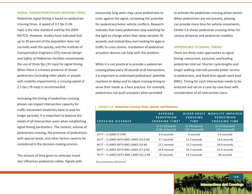
EXHIBIT5.6PedestrianCrossingTimes,Speeds,andDistances
SIGNAL TIMING/PEDESTRIAN CROSSING TIMES
Pedestrian signal timing is based on pedestrian
crossing times. A speed of 3.5 fps (1.06
mps) is the new standard used by the 2009
MUTCD. However, studies have indicated that
up to 30 percent of the population does not
normally walk this quickly, and the Institute of
Transportation Engineers (ITE) manual Design
and Safety of Pedestrian Facilities recommends
the use of three fps (.91 mps) for signal timing.
When there is a known presence of slower
pedestrians (including older adults or people
with mobility impairments), a crossing speed of
2.5 fps (.76 mps) is recommended.
Increasing the timing of pedestrian crossing
phases can impact intersection capacity for
traffic movement (motorists have to wait for
longer periods). It is important to balance the
needs of all intersection users when establishing
signal timing parameters. The context, volume of
pedestrians crossing, the presence of pedestrians
with special needs, and other factors need to be
considered in the decision-making process.
The amount of time given to vehicular travel
also influences pedestrian safety. Signals with
excessively long waits may cause pedestrians to
cross against the signal, increasing the potential
for pedestrian/motor vehicle conflicts. Research
indicates that many pedestrians stop watching for
the light to change when their delay exceeds 30
seconds, and instead they start looking for gaps in
traffic to cross streets. Installation of pedestrian
actuation devices can help with this problem.
While it is not practical to provide a pedestrian
crossing phase every 30 seconds at all intersections,
it is important to understand pedestrians’ potential
reactions to delays and to adjust crossing timing to
serve their needs as a best practice. For example,
pedestrians can push actuators when provided
to activate the pedestrian crossing phase sooner.
When pedestrians are not present, phasing
can provide more time for vehicle movements.
Exhibit 5.6 shows pedestrian crossing times for
various distances and pedestrian mobility.
APPROACHES TO SIGNAL TIMING
There are three main approaches to signal
timing: concurrent, exclusive, and leading
pedestrian interval. Shorter cycle lengths and
longer walking intervals provide better service
to pedestrians, and fixed time signals work best
(PBIC). Timing for each intersection needs to be
analyzed and set on a case-by-case basis with
consideration of all intersection users.

Intersections and Crossings
5-10
Pedestrian scramble markings
No right-turn on red enables operation of the pedestrian scramble.
EXHIBIT5.7ExclusiveSignalTiming:Atapedestrianscramblealltrafficisstoppedandpedestrianscancrossinanydirection.
• ConcurrentTiming: The green traffic signal and
the walk signal go on simultaneously. Turning
motorists are expected to yield to pedestrians
in the crosswalk. This type of timing usually
provides pedestrians with the shortest waiting
times and most opportunities to cross.
• ExclusiveTiming:Stops traffic in all directions
and should be used in conjunction with “no
right on red.” It is useful where there are very
high pedestrian volumes (more than 1,200
pedestrian crossings per day per the PBIC), high
speed roadways, and high turning movement
conflicts. However, pedestrians usually have a
long wait for the exclusive signal and may be
tempted to cross against the signal, negating
the benefits of the exclusive phase. It is also
difficult for visually impaired pedestrians who
lose the aural cue of traffic moving in one
direction or another. The exclusive pedestrian
phase increases safety with a crash reduction
factor (CRF) of 34 percent, but decreases the
efficiency of the intersection (PBIC). Exhibit 5.7
illustrates exclusive timing and the application
of a pedestrian scramble at an intersection.
• LeadingPedestrianInterval(LPI): The walk
signal goes on several seconds before the
Intersections and Crossings
5-11
green traffic signal, allowing pedestrians to
enter the crosswalk first, protecting them
from turning vehicles and making them
more visible to motorists. This technique
has been used in New York City successfully
for two decades, as well as other cities.
LPI is especially good for dual-lane turning
movements (PBIC, Crossing Signals), and
is also often used in conjunction with “No
Right-turn on Red” signs.
Signal timing uses the following intervals:
• Walk (or Walking) Interval
• Pedestrian Change (or Clearance) Interval
• Buffer Interval
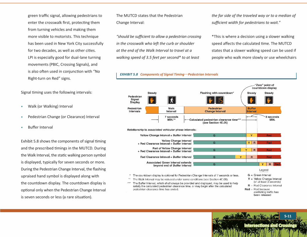
Exhibit 5.8 shows the components of signal timing
and the prescribed timings in the MUTCD. During
the Walk Interval, the static walking person symbol
is displayed, typically for seven seconds or more.
During the Pedestrian Change Interval, the flashing
upraised hand symbol is displayed along with
the countdown display. The countdown display is
optional only when the Pedestrian Change Interval
is seven seconds or less (a rare situation).
The MUTCD states that the Pedestrian
Change Interval:
“should be sufficient to allow a pedestrian crossing
in the crosswalk who left the curb or shoulder
at the end of the Walk Interval to travel at a
walking speed of 3.5 feet per second* to at least
EXHIBIT5.8ComponentsofSignalTiming—PedestrianIntervals
Timing Traffic Signals to Accommodate Pedestrians
FACT SHEEThttp://www.nysmpos.org
The Walk Interval should be at least 7 seconds, although the MUTCD allows “If pedestrian volumes and characteristics do not require a 7-second walk interval, walk intervals as short as 4 seconds may be used.” MUTCD §4E-06,¶12
The Pedestrian Clearance Time “should be sufficient to allow a pedestrian crossing in the crosswalk who left the curb or shoulder at the end of the WALKING PERSON (symbolizing WALK) signal indication to travel at a walking speed of 3.5 feet per second* to at least the far side of the traveled way or to a median of sufficient width for pedestrians to wait.” MUTCD §4E-06, ¶7 *This is where a decision about using a slower walking speed affects the calculated time.
A Pedestrian Buffer Interval of at least 3 seconds shall be displayed prior to the release of any conflicting vehicular movement.
All pedestrian signal heads used at crosswalks where the pedestrian change interval is more than 7 seconds shall include a pedestrian change interval countdown display.” MUTCD 4E.07
Crossings with high pedestrian volume and a high volume of conflicting turning vehicles can be a safety hazard. A signal timing technique that may be considered in that situation is a Leading Pedestrian Interval. This is an extension of the All-Red clearance phase during which the WALK indication is displayed for the direction which will receive the next green phase. This allows pedestrians to proceed into the crosswalk prior to any vehicles, making them more visible to drivers. This may also be considered at suburban intersections with lower pedestrian volume, but a clear conflict with turning vehicles.
“If a leading pedestrian interval is used, it should be at least 3 seconds in duration and should be timed to allow pedestrians to cross at least one lane of traffic or, in the case
of a large corner radius, to travel far enough for pedestrians to establish their position ahead of the turning traffic before the turning traffic is released.” MUTCD §4E-06 ¶22 The MUTCD further states that if a leading pedestrian interval is used, accessible pedestrian signals should be considered.
Prohibiting Right Turn on RedRemember to review the requirements for prohibiting right turn on red. As stated in the MUTCD, a No Turn on Red sign should be considered when an engineering study finds that one or more of the following conditions exists:
□ Inadequate sight distance to vehicles approaching from the left (or right, if applicable);
□ Geometrics or operational characteristics of the intersection that might result in unexpected conflicts;
□ An exclusive pedestrian phase;
□ An unacceptable number of pedestrian conflicts with right-turn-on-red maneuvers, especially involving children, older pedestrians, or persons with disabilities;
□ More than three right-turn-on-red accidents reported in a 12-month period for the particular approach; or
□ The skew angle of the intersecting roadways creates difficulty for drivers to see traffic approaching from their left. MUTCD, §2B.54
Pedestrian Intervals
The above figure from the MUTCD shows the components of pedestrian signal timing and the manner in which they may be used.
While this fact sheet addresses only traffic signal timing, intersection design features such as corner bulb-outs and median refuges can reduce the crossing distance, and therefore the required pedestrian clearance time, while making the intersection more pedestrian-friendly.
the far side of the traveled way or to a median of
sufficient width for pedestrians to wait.”
*This is where a decision using a slower walking
speed affects the calculated time. The MUTCD
states that a slower walking speed can be used if
people who walk more slowly or use wheelchairs

Intersections and Crossings
5-12
1. Dark until Activated 2. Flashing Yellow Upon Activation 3. Steady Yellow 4. Steady Red During Pedestrian Walk Interval
5. Alternating Flashing Red During Pedestrian Clearance Interval
6. Dark Again Until Activated
EXHIBIT5.10SequenceforaPedestrianHybridBeacon
SY - Steady yellowFY - Flashing yellowSR - Steady redFR - Flashing red
LEGEND
Raised Hand: Don’t Walk Signal
Walking Person:Walking Interval Signal
Flashing Hand with Countdown:Pedestrian Change Interval
or
EXHIBIT5.9PedestrianSignalHeads:PBICrecommendsbeginningthecountdownsignalwiththeWalkingIntervalPhase.
“routinely use the crosswalk.” This involves
engineering judgment. Current research suggests
that if more than 20 percent of the people in the
pedestrian stream are elderly, a slower walking
speed of 3 fps should be used.
The Buffer Interval shall be displayed for at least
three seconds prior to the release of any conflicting
vehicular movement. The Buffer Interval displays
the steady (non-flashing) upraised hand symbol.
The introduction of the countdown display
reduces confusion among pedestrians who find
themselves in the middle of an intersection
and are puzzled by the meaning of the flashing
upraised hand sign. However, many existing
intersections lack the countdown display and
should be retrofitted with them. Countdown
signals provide better pedestrian safety. Results
from a San Francisco study showed that there was
a 25 percent CRF after countdown signals were
installed (PBIC). Exhibit 5.9 illustrates pedestrian
signal heads, including countdown displays.
Traffic signals are usually timed for vehicle
speeds, causing pedestrians to have to stop at
nearly every intersection.
5-13
Intersections and Crossings
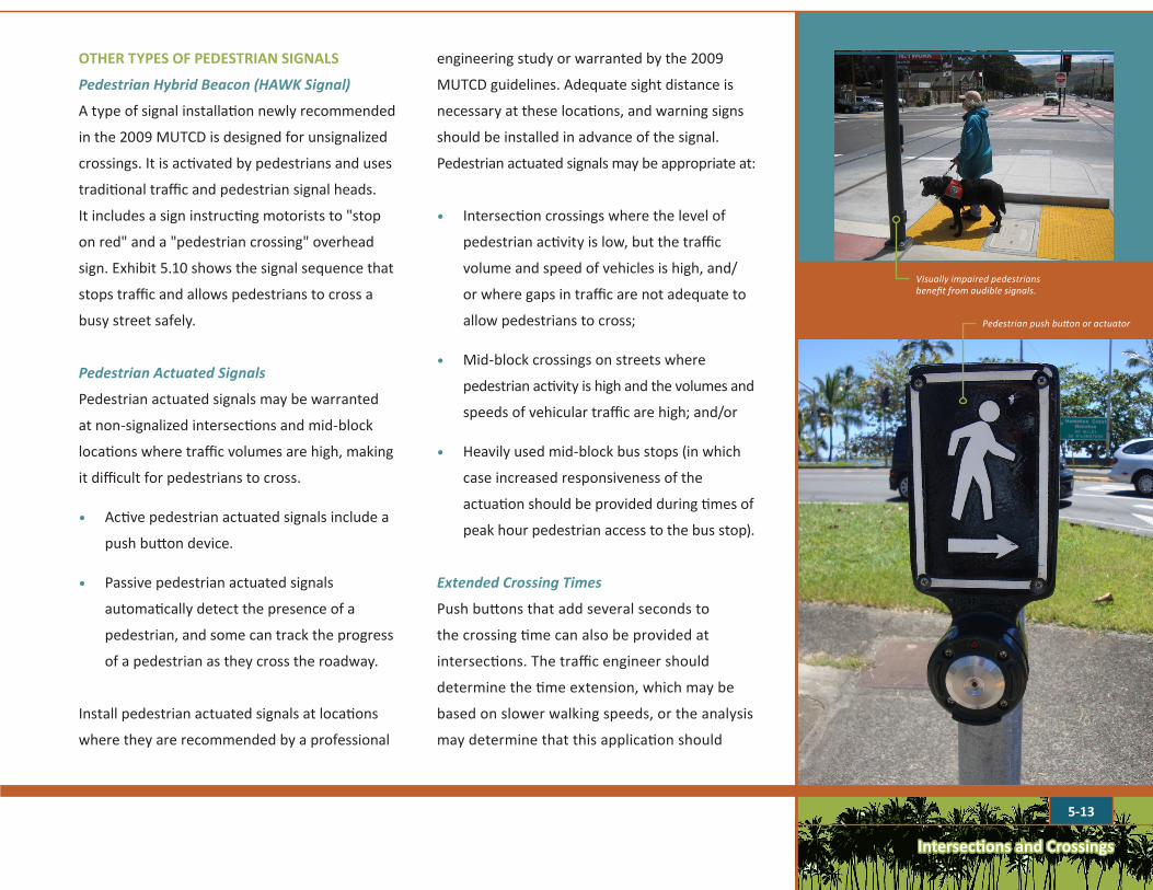
OTHER TYPES OF PEDESTRIAN SIGNALS
PedestrianHybridBeacon(HAWKSignal)
A type of signal installation newly recommended
in the 2009 MUTCD is designed for unsignalized
crossings. It is activated by pedestrians and uses
traditional traffic and pedestrian signal heads.
It includes a sign instructing motorists to "stop
on red" and a "pedestrian crossing" overhead
sign. Exhibit 5.10 shows the signal sequence that
stops traffic and allows pedestrians to cross a
busy street safely.
PedestrianActuatedSignals
Pedestrian actuated signals may be warranted
at non-signalized intersections and mid-block
locations where traffic volumes are high, making
it difficult for pedestrians to cross.
• Active pedestrian actuated signals include a
push button device.
• Passive pedestrian actuated signals
automatically detect the presence of a
pedestrian, and some can track the progress
of a pedestrian as they cross the roadway.
Install pedestrian actuated signals at locations
where they are recommended by a professional
engineering study or warranted by the 2009
MUTCD guidelines. Adequate sight distance is
necessary at these locations, and warning signs
should be installed in advance of the signal.
Pedestrian actuated signals may be appropriate at:
• Intersection crossings where the level of
pedestrian activity is low, but the traffic
volume and speed of vehicles is high, and/
or where gaps in traffic are not adequate to
allow pedestrians to cross;
• Mid-block crossings on streets where
pedestrian activity is high and the volumes and
speeds of vehicular traffic are high; and/or
• Heavily used mid-block bus stops (in which
case increased responsiveness of the
actuation should be provided during times of
peak hour pedestrian access to the bus stop).
ExtendedCrossingTimes
Push buttons that add several seconds to
the crossing time can also be provided at
intersections. The traffic engineer should
determine the time extension, which may be
based on slower walking speeds, or the analysis
may determine that this application should
Pedestrian push button or actuator
Visually impaired pedestrians benefit from audible signals.
Intersections and Crossings
5-14
not be installed at the intersection for various
reasons, such as major impacts to traffic
capacity. (The needs of all intersection users
have to be balanced.) Extended crossing times
may improve pedestrian safety at:
• Crossings near a hospital, nursing home,
retirement home, or other facility that
accommodates mobility impaired people;
• Intersections where pedestrian volume
varies widely over the course of a day; and
• Other locations as determined through
analysis of the context and traffic conditions
on a case-by-case basis.
AudibleDevices
Audible devices should be considered in areas
where a high number of visually impaired
pedestrians use the crossing. This may occur near
hospitals, retirement homes, or special facilities for
the visually impaired. Audible devices should be
separated by at least ten feet to avoid confusion
about which crossing is open. In some cases it
may be wise to include verbal commands to clarify
which street to cross. See Toolbox Section 3—
Accessibility for additional information.
10' (3 m
) min
18” (45.7 cm) min
18” (45.7 cm)min
6’ (1.8 m)max
6’ (1.8 m) max
5’ (1.5 m)max
5’ (1.5 m)max
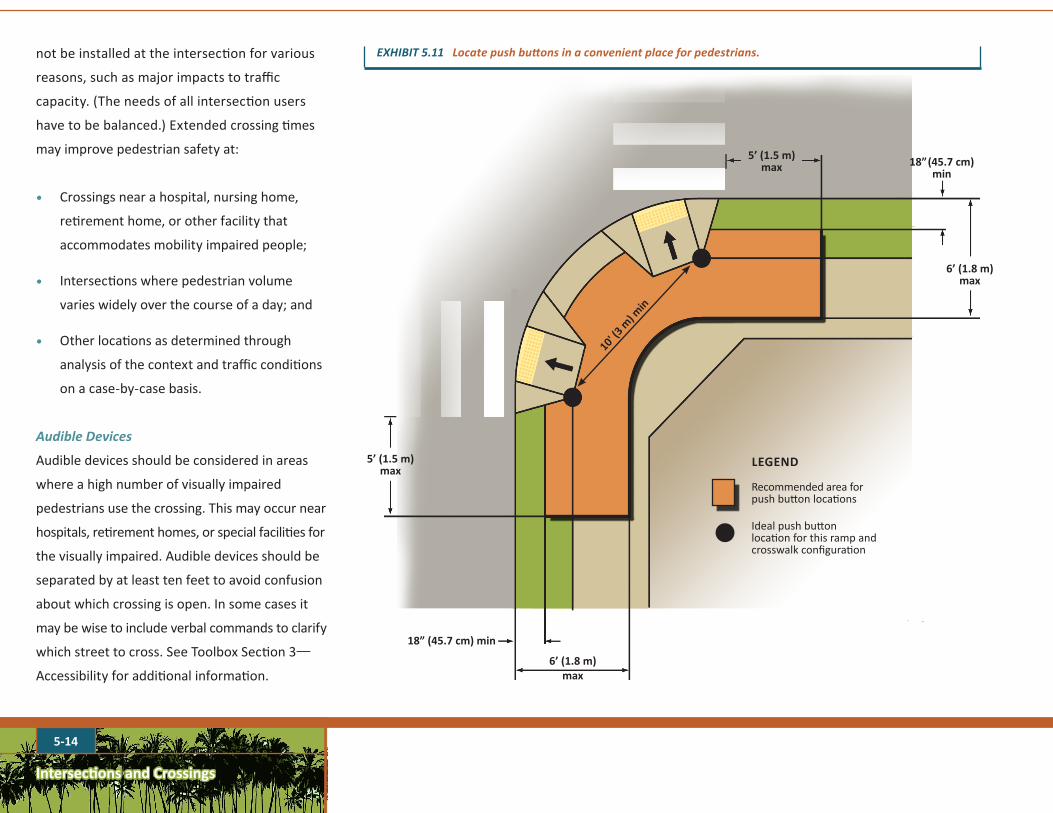
EXHIBIT5.11Locatepushbuttonsinaconvenientplaceforpedestrians.
LEGEND
Recommended area for push button locations
Ideal push button location for this ramp and crosswalk configuration
Intersections and Crossings
5-15
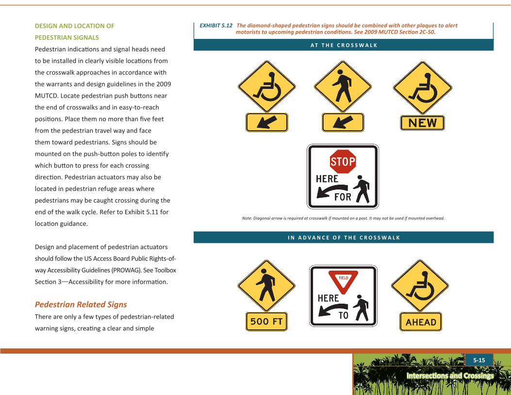
EXHIBIT5.12Thediamond-shapedpedestriansignsshouldbecombinedwithotherplaquestoalertmotoriststoupcomingpedestrianconditions.See2009MUTCDSection2C-50.
Note: Diagonal arrow is required at crosswalk if mounted on a post. It may not be used if mounted overhead.
A T T H E C R O S S W A L K
I N A D V A N C E O F T H E C R O S S W A L K
DESIGN AND LOCATION OF
PEDESTRIAN SIGNALS
Pedestrian indications and signal heads need
to be installed in clearly visible locations from
the crosswalk approaches in accordance with
the warrants and design guidelines in the 2009
MUTCD. Locate pedestrian push buttons near
the end of crosswalks and in easy-to-reach
positions. Place them no more than five feet
from the pedestrian travel way and face
them toward pedestrians. Signs should be
mounted on the push-button poles to identify
which button to press for each crossing
direction. Pedestrian actuators may also be
located in pedestrian refuge areas where
pedestrians may be caught crossing during the
end of the walk cycle. Refer to Exhibit 5.11 for
location guidance.
Design and placement of pedestrian actuators
should follow the US Access Board Public Rights-of-
way Accessibility Guidelines (PROWAG). See Toolbox
Section 3—Accessibility for more information.
PedestrianRelatedSignsThere are only a few types of pedestrian-related
warning signs, creating a clear and simple
Intersections and Crossings
5-16
(PBIC). Existing roadway lighting may need to
be supplemented with additional pedestrian
lighting in areas of heavy pedestrian traffic,
at locations where motorists may not expect
a crossing, or in other areas determined by a
traffic safety analysis or local design priorities.
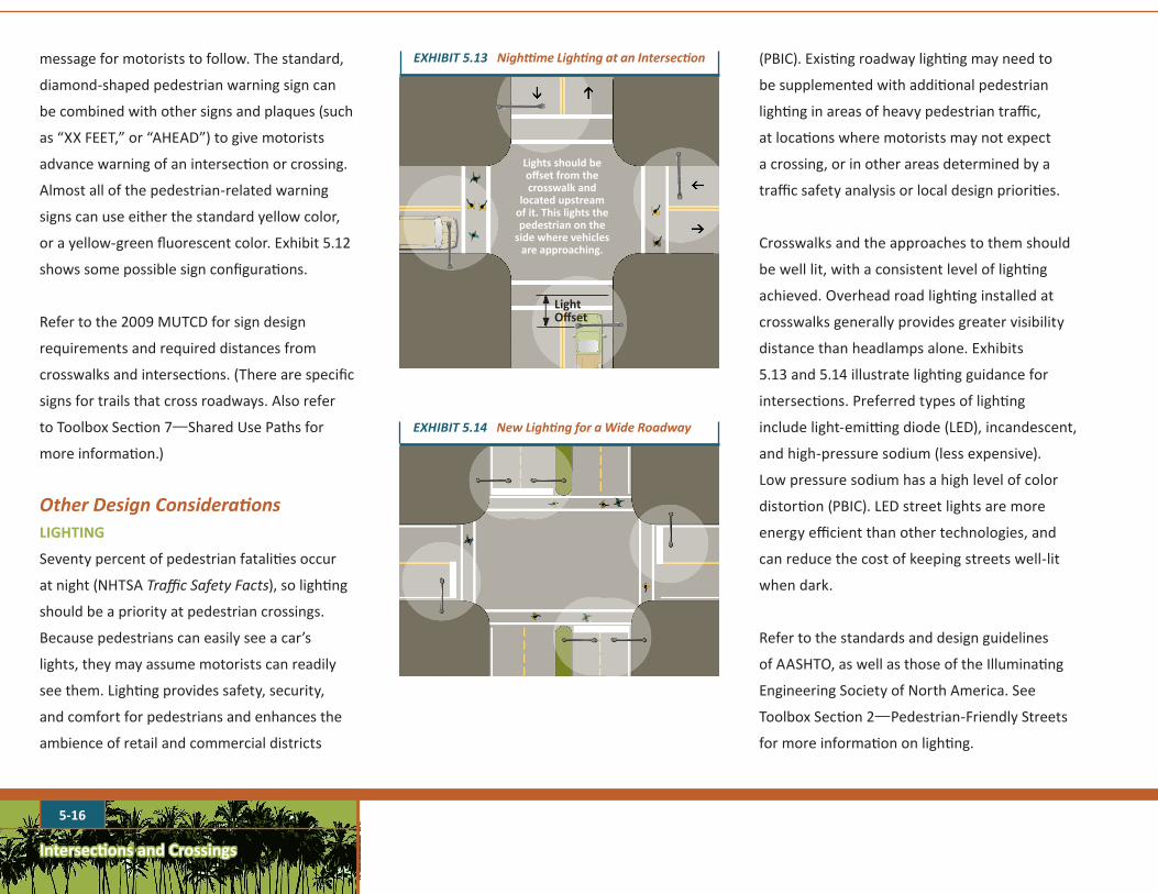
Crosswalks and the approaches to them should
be well lit, with a consistent level of lighting
achieved. Overhead road lighting installed at
crosswalks generally provides greater visibility
distance than headlamps alone. Exhibits
5.13 and 5.14 illustrate lighting guidance for
intersections. Preferred types of lighting
include light-emitting diode (LED), incandescent,
and high-pressure sodium (less expensive).
Low pressure sodium has a high level of color
distortion (PBIC). LED street lights are more
energy efficient than other technologies, and
can reduce the cost of keeping streets well-lit
when dark.
Refer to the standards and design guidelines
of AASHTO, as well as those of the Illuminating
Engineering Society of North America. See
Toolbox Section 2—Pedestrian-Friendly Streets
for more information on lighting.
Light Offset
Lights should be offset from the crosswalk and
located upstream of it. This lights the pedestrian on the
side where vehicles are approaching.
EXHIBIT5.13NighttimeLightingatanIntersection
EXHIBIT5.14NewLightingforaWideRoadway
message for motorists to follow. The standard,
diamond-shaped pedestrian warning sign can
be combined with other signs and plaques (such
as “XX FEET,” or “AHEAD”) to give motorists
advance warning of an intersection or crossing.
Almost all of the pedestrian-related warning
signs can use either the standard yellow color,
or a yellow-green fluorescent color. Exhibit 5.12
shows some possible sign configurations.
Refer to the 2009 MUTCD for sign design
requirements and required distances from
crosswalks and intersections. (There are specific
signs for trails that cross roadways. Also refer
to Toolbox Section 7—Shared Use Paths for
more information.)
OtherDesignConsiderationsLIGHTING
Seventy percent of pedestrian fatalities occur
at night (NHTSA Traffic Safety Facts), so lighting
should be a priority at pedestrian crossings.
Because pedestrians can easily see a car’s
lights, they may assume motorists can readily
see them. Lighting provides safety, security,
and comfort for pedestrians and enhances the
ambience of retail and commercial districts
Intersections and Crossings
5-17
LOCATION OF DRAINAGE INLETS AND GRATES
Drainage grates should be located away from
crosswalks and curb ramps and outside the
route of pedestrian travel. Locate drainage
inlets on the upstream side of the crosswalk
to avoid excessive drainage flows across the
crossing area. Direct road and gutter drainage
away from intersection corners and walking
areas. This is particularly important given
Hawaii’s rainfall patterns. The grate tops shall be
designed in accordance with PROWAG.
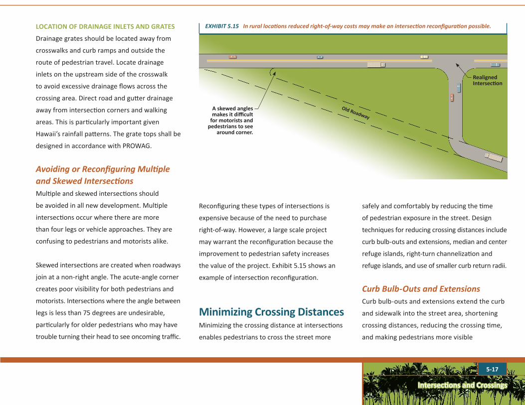
AvoidingorReconfiguringMultipleandSkewedIntersectionsMultiple and skewed intersections should
be avoided in all new development. Multiple
intersections occur where there are more
than four legs or vehicle approaches. They are
confusing to pedestrians and motorists alike.
Skewed intersections are created when roadways
join at a non-right angle. The acute-angle corner
creates poor visibility for both pedestrians and
motorists. Intersections where the angle between
legs is less than 75 degrees are undesirable,
particularly for older pedestrians who may have
trouble turning their head to see oncoming traffic.
Old Roadway
Realigned Intersection
A skewed angles makes it difficult
for motorists and pedestrians to see
around corner.
EXHIBIT5.15Inrurallocationsreducedright-of-waycostsmaymakeanintersectionreconfigurationpossible.
Reconfiguring these types of intersections is
expensive because of the need to purchase
right-of-way. However, a large scale project
may warrant the reconfiguration because the
improvement to pedestrian safety increases
the value of the project. Exhibit 5.15 shows an
example of intersection reconfiguration.
Minimizing Crossing Distances Minimizing the crossing distance at intersections
enables pedestrians to cross the street more
safely and comfortably by reducing the time
of pedestrian exposure in the street. Design
techniques for reducing crossing distances include
curb bulb-outs and extensions, median and center
refuge islands, right-turn channelization and
refuge islands, and use of smaller curb return radii.
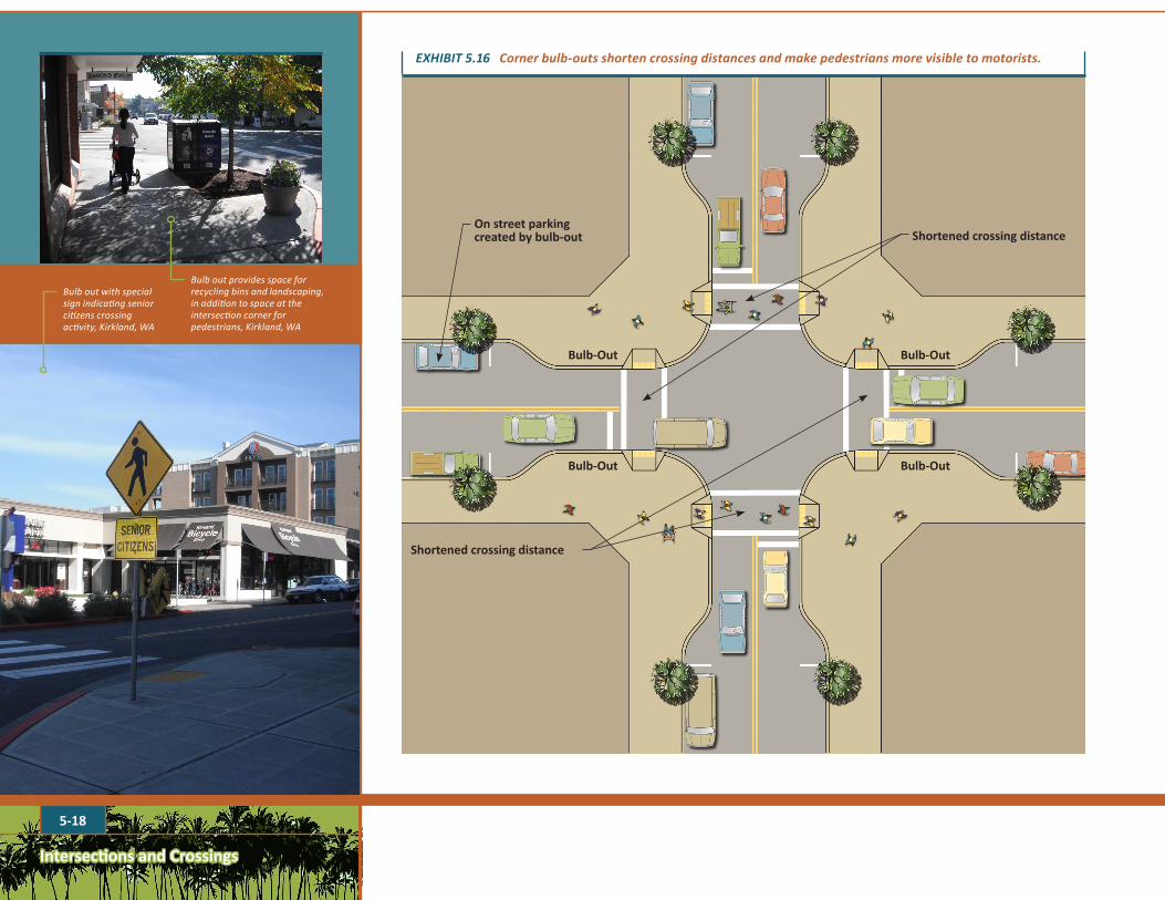
CurbBulb-OutsandExtensionsCurb bulb-outs and extensions extend the curb
and sidewalk into the street area, shortening
crossing distances, reducing the crossing time,
and making pedestrians more visible
5-18
Intersections and Crossings
On street parking created by bulb-out
Bulb-Out
Bulb-Out
Shortened crossing distance
Shortened crossing distance
EXHIBIT5.16Cornerbulb-outsshortencrossingdistancesandmakepedestriansmorevisibletomotorists.
Bulb-Out
Bulb-Out
Bulb out with special sign indicating senior citizens crossing activity, Kirkland, WA
Bulb out provides space for recycling bins and landscaping, in addition to space at the intersection corner for pedestrians, Kirkland, WA
Intersections and Crossings
5-19
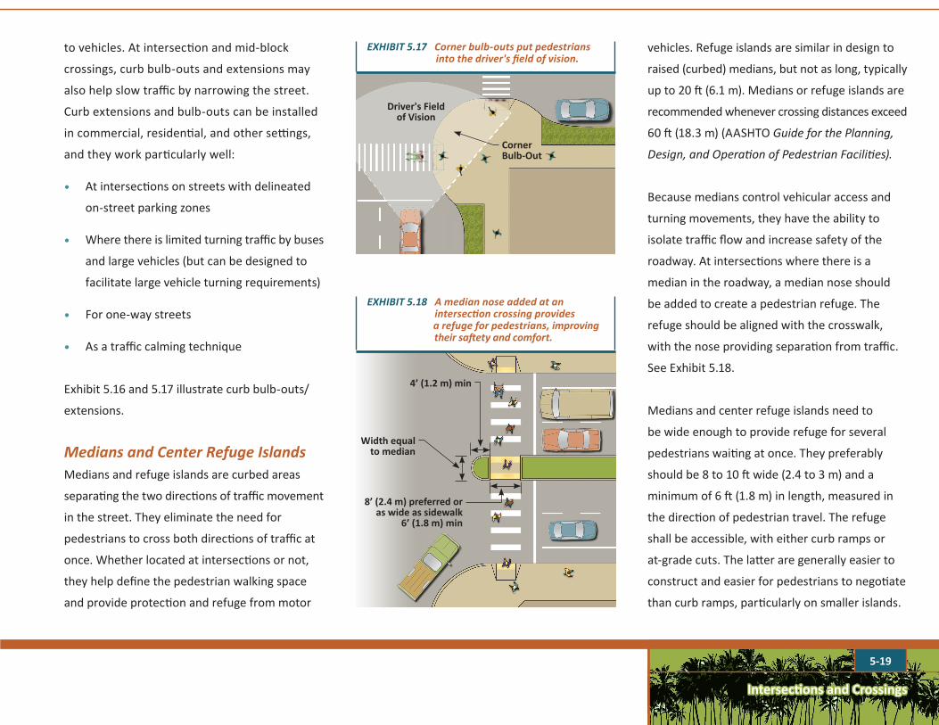
EXHIBIT5.17Cornerbulb-outsputpedestriansintothedriver'sfieldofvision.
Driver's Field of Vision
Corner Bulb-Out
4’ (1.2 m) min
Width equal to median
8’ (2.4 m) preferred or as wide as sidewalk
6’ (1.8 m) min
EXHIBIT5.18Amediannoseaddedatan intersectioncrossingprovidesarefugeforpedestrians,improvingtheirsaftetyandcomfort.
to vehicles. At intersection and mid-block
crossings, curb bulb-outs and extensions may
also help slow traffic by narrowing the street.
Curb extensions and bulb-outs can be installed
in commercial, residential, and other settings,
and they work particularly well:
• At intersections on streets with delineated
on-street parking zones
• Where there is limited turning traffic by buses
and large vehicles (but can be designed to
facilitate large vehicle turning requirements)
• For one-way streets
• As a traffic calming technique
Exhibit 5.16 and 5.17 illustrate curb bulb-outs/
extensions.
MediansandCenterRefugeIslandsMedians and refuge islands are curbed areas
separating the two directions of traffic movement
in the street. They eliminate the need for
pedestrians to cross both directions of traffic at
once. Whether located at intersections or not,
they help define the pedestrian walking space
and provide protection and refuge from motor
vehicles. Refuge islands are similar in design to
raised (curbed) medians, but not as long, typically
up to 20 ft (6.1 m). Medians or refuge islands are
recommended whenever crossing distances exceed
60 ft (18.3 m) (AASHTO Guide for the Planning,
Design, and Operation of Pedestrian Facilities).
Because medians control vehicular access and
turning movements, they have the ability to
isolate traffic flow and increase safety of the
roadway. At intersections where there is a
median in the roadway, a median nose should
be added to create a pedestrian refuge. The
refuge should be aligned with the crosswalk,
with the nose providing separation from traffic.
See Exhibit 5.18.
Medians and center refuge islands need to
be wide enough to provide refuge for several
pedestrians waiting at once. They preferably
should be 8 to 10 ft wide (2.4 to 3 m) and a
minimum of 6 ft (1.8 m) in length, measured in
the direction of pedestrian travel. The refuge
shall be accessible, with either curb ramps or
at-grade cuts. The latter are generally easier to
construct and easier for pedestrians to negotiate
than curb ramps, particularly on smaller islands.
Intersections and Crossings
5-20
Provide pedestrian push buttons at the refuge
when the signal timing doesn't allow all
pedestrians to cross the entire street on one
crossing phase. Accessible pedestrian signals (APS)
shall be provided in accordance with PROWAG.
These areas shall be clear of obstacles such as
utilities, including signal control boxes, signal
and light poles, signs, and landscaping above
two feet in height.
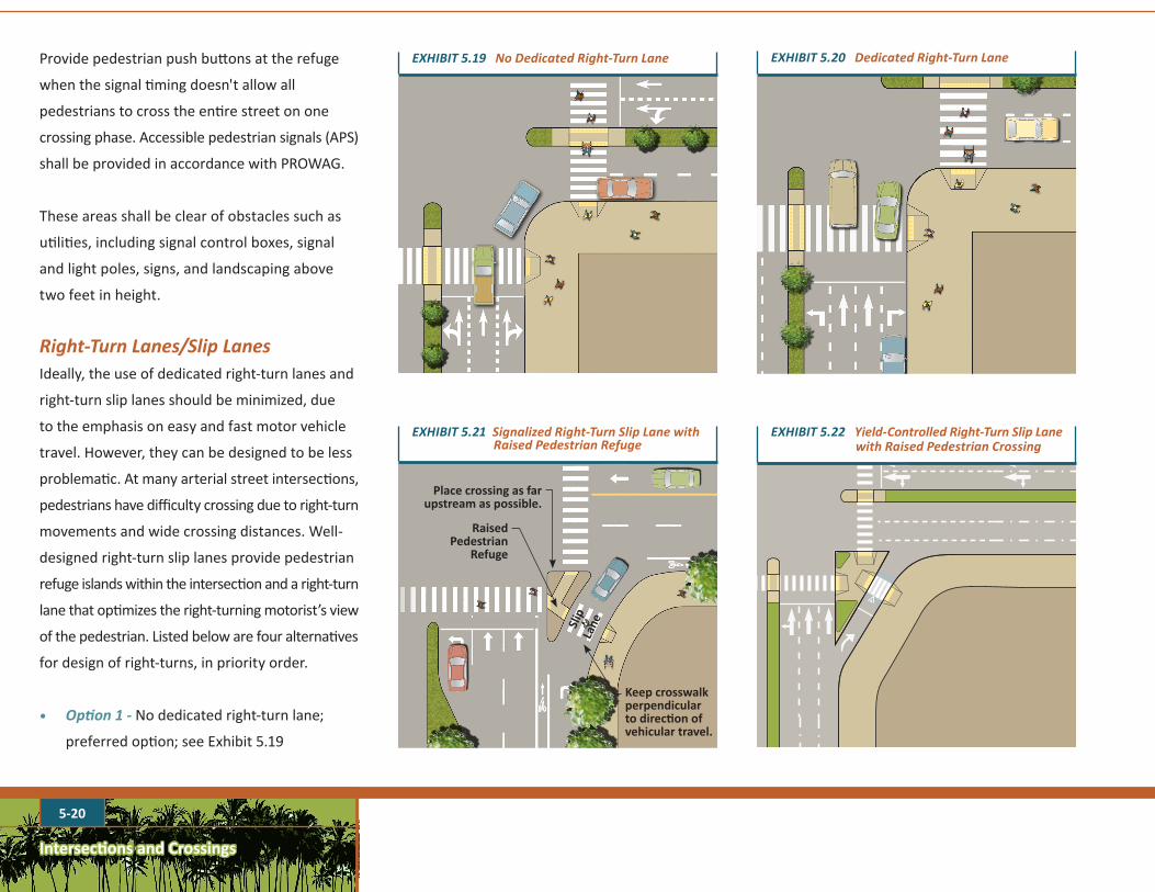
Right-TurnLanes/SlipLanesIdeally, the use of dedicated right-turn lanes and
right-turn slip lanes should be minimized, due
to the emphasis on easy and fast motor vehicle
travel. However, they can be designed to be less
problematic. At many arterial street intersections,
pedestrians have difficulty crossing due to right-turn
movements and wide crossing distances. Well-
designed right-turn slip lanes provide pedestrian
refuge islands within the intersection and a right-turn
lane that optimizes the right-turning motorist’s view
of the pedestrian. Listed below are four alternatives
for design of right-turns, in priority order.
• Option1-No dedicated right-turn lane;
preferred option; see Exhibit 5.19
EXHIBIT5.19NoDedicatedRight-TurnLane EXHIBIT5.20DedicatedRight-TurnLane
EXHIBIT5.22Yield-ControlledRight-TurnSlipLanewithRaisedPedestrianCrossing
Raised Pedestrian
Refuge
Place crossing as far upstream as possible.
Keep crosswalk perpendicular to direction of vehicular travel.
Slip
Lane
EXHIBIT5.21SignalizedRight-TurnSlipLanewithRaisedPedestrianRefuge

Intersections and Crossings
5-21
• Option2-Dedicated right-turn lane; see
Exhibit 5.20
• Option3- Signalized right-turn slip lane with
raised pedestrian crossing; see Exhibit 5.21
• Option4-Yield-controlled right-turn slip lane
with raised pedestrian crossing; see Exhibit 5.22
The provision of a channelized right-turn lane
is appropriate only on signalized approaches
where right-turning volumes are high or
large vehicles frequently turn and conflicting
pedestrian volumes are low and are not
expected to increase greatly.
EXHIBIT5.23PreferredDesignofaChannelizedRight-TurnLane(KimleyHornandAssociates,Inc.adaptedfromanillustrationbyDanBurden)
The design of a channelized right turn and refuge
island should follow the recommended approach
in Exhibit 5.23. The exhibit depicts two designs
of a channelized right-turn lane. The first shows
a wide angle design with a high-speed, low
visibility of pedestrians with a 20 degree to 142
degree angle. The second design shows a tighter
angle showing a 20 degree to 112 degree angle,
with a 55 to 60 degree angle between vehicle
flows. Historically, channelized right-turns were
often designed like the first example, which is no
longer a recommended practice. The preferred
design uses an approach angle that lowers
speeds and improves visibility.
When channelized right-turn lanes are justified
for traffic capacity or large vehicle purposes, the
following practices should be used:
• Provide a low-angle right turn (about 112
degrees). This angle slows down the speed
of right-turning vehicles and improves driver
visibility of pedestrians within and approaching
the crosswalk (as shown in Exhibit 5.23).
• Place crosswalks so that a motorist has a
clear view of pedestrians.
NOTRECOMMENDED RECOMMENDED
Highspeed,lowvisibilityofpedestrians
Vehiclespeeds17to18mph,goodvisibilityofpedestrians
WIDE ANGLE TIGHTER ANGLE
20° 20°
146°112°
20° 20°
55to60degreeanglebetweenvehicleflows
Intersections and Crossings
5-22
• Unless the turning radii of large vehicles,
such as tractor-trailers or buses must
be accommodated, the pavement in the
channelized right-turn lane should be no
wider than 16 feet. For any width right-turn
lane, mark edge lines and cross-hatching to
restrict the painted width of the travel way
of the channelized right-turn lane to 12 ft
(3.6 m) to slow smaller vehicles.
• If vehicle-pedestrian conflicts are a
significant problem in the channelized right-
turn lane, it might be appropriate to provide
signing to remind drivers of their legal
obligation to yield to pedestrians crossing
the lane in the marked crosswalk. Regulatory
signs such as the TURNING TRAFFIC MUST
YIELD TO PEDESTRIANS (R10-15) or warning
signs such as the PEDESTRIAN CROSSING
(W11-2) could be placed in advance of or at
the crossing location.
At locations with extremely high numbers of
right-turning movements, slip lanes should be
equipped with a signal to provide pedestrians
opportunities to cross. See previous discussion in
this section pertaining to signalization.
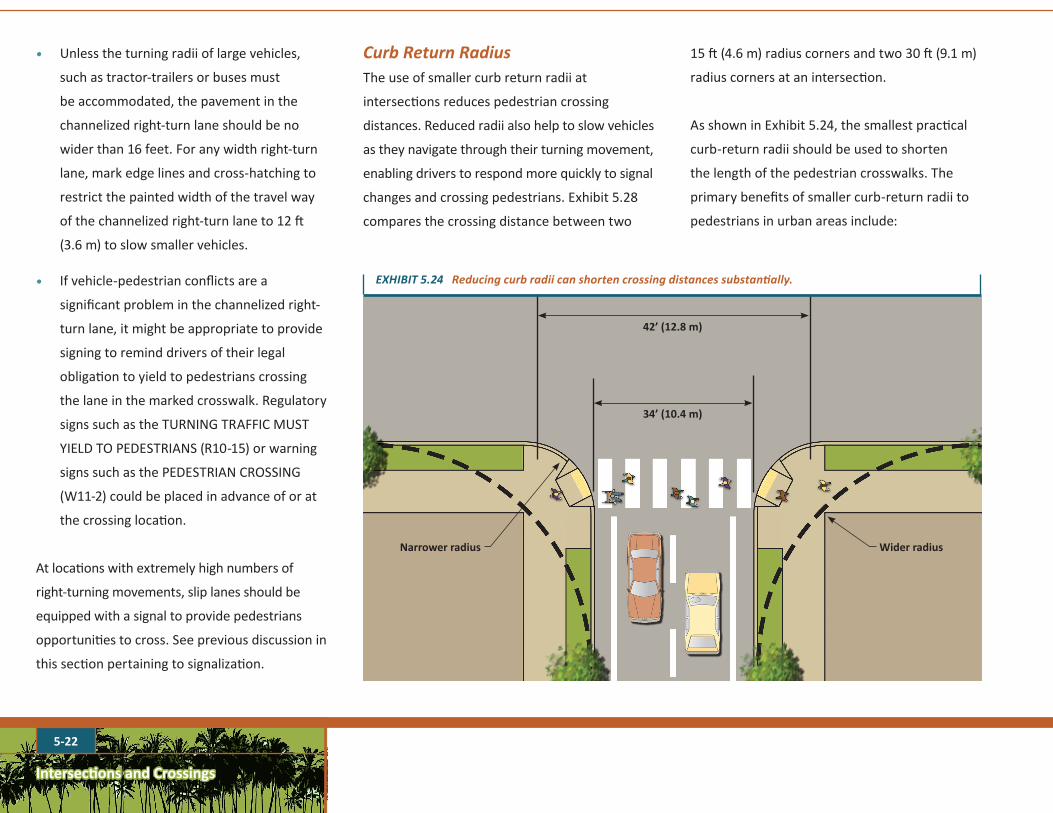
CurbReturnRadiusThe use of smaller curb return radii at
intersections reduces pedestrian crossing
distances. Reduced radii also help to slow vehicles
as they navigate through their turning movement,
enabling drivers to respond more quickly to signal
changes and crossing pedestrians. Exhibit 5.28
compares the crossing distance between two
Wider radiusNarrower radius
42’ (12.8 m)
34’ (10.4 m)
15 ft (4.6 m) radius corners and two 30 ft (9.1 m)
radius corners at an intersection.
As shown in Exhibit 5.24, the smallest practical
curb-return radii should be used to shorten
the length of the pedestrian crosswalks. The
primary benefits of smaller curb-return radii to
pedestrians in urban areas include:
EXHIBIT5.24Reducingcurbradiicanshortencrossingdistancessubstantially.
Intersections and Crossings
5-23
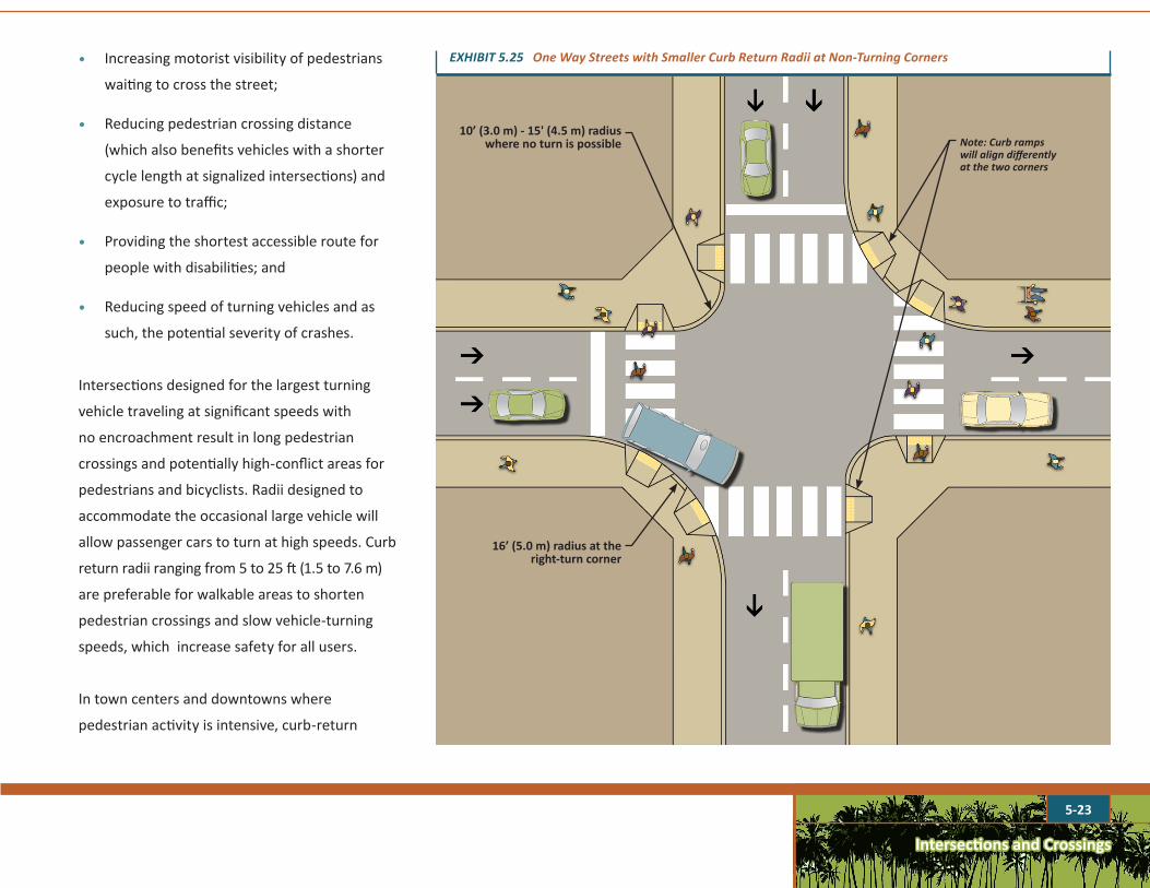
10’ (3.0 m) - 15' (4.5 m) radiuswhere no turn is possible
16’ (5.0 m) radius at the right-turn corner
Note:Curbrampswillaligndifferentlyatthetwocorners
EXHIBIT5.25OneWayStreetswithSmallerCurbReturnRadiiatNon-TurningCorners• Increasing motorist visibility of pedestrians
waiting to cross the street;
• Reducing pedestrian crossing distance
(which also benefits vehicles with a shorter
cycle length at signalized intersections) and
exposure to traffic;
• Providing the shortest accessible route for
people with disabilities; and
• Reducing speed of turning vehicles and as
such, the potential severity of crashes.
Intersections designed for the largest turning
vehicle traveling at significant speeds with
no encroachment result in long pedestrian
crossings and potentially high-conflict areas for
pedestrians and bicyclists. Radii designed to
accommodate the occasional large vehicle will
allow passenger cars to turn at high speeds. Curb
return radii ranging from 5 to 25 ft (1.5 to 7.6 m)
are preferable for walkable areas to shorten
pedestrian crossings and slow vehicle-turning
speeds, which increase safety for all users.
In town centers and downtowns where
pedestrian activity is intensive, curb-return
Intersections and Crossings
5-24
radii should be as small as possible. On multi-
lane streets and roadways, large vehicles may
encroach into the adjacent travel lanes (in the
same direction of travel) when turning. Curb-
return radii of different lengths can be used on
different corners of the same intersection to
match the design vehicle turning at that corner.
On one way streets there is an opportunity to
shorten the radii of the corners where vehicles
do not turn, as shown in Exhibit 5.25.
At intersections with no vehicle turns, the
minimum curb return radii should be 5 ft (1.5 m).
A curb return radius of 5 to 15 ft (1.5 to 4.5 m)
should be used where:
1. High pedestrian volumes are present or
reasonably anticipated;
2. Volumes of turning vehicles are low;
3. The width of the receiving intersection
approach can accommodate a turning
passenger vehicle without encroachment
into the opposing lane;
4. Large vehicles constitute a very low
proportion of the turning vehicles;
5. Bicycle and parking lanes create additional
space to accommodate the "effective" turning
radius of vehicles;
6. Low turning speeds are required or desired;
and
7. Occasional encroachment of turning
school bus, moving van, fire truck, or
oversized delivery truck into an opposing
lane is acceptable.
Curb radii may need to be larger where:
1. Occasional encroachment of a turning
bus, school bus, moving van, fire truck, or
oversized delivery truck into the opposing
lane is not acceptable;
2. Curb extensions are proposed or might be
added in the future; and
3. Receiving thoroughfare does not have
parking or bicycle lanes and the receiving
lane is less than 12 ft (3.6 m) in width.
An alternative to increasing curb-return radii is
setting back the stop line of the receiving street
to allow large vehicles to swing into opposing
lane as they turn. Setbacks to accommodate
right-turn encroachment need to be examined
on a case-by-case basis since very tight right
turns may require long setbacks.
RECOMMENDATIONS FOR TRUCK ROUTES
Truck routes should be designated outside of
or on a minimum number of streets in
walkable areas to reduce the impact of large
turning radii. Where designated truck routes
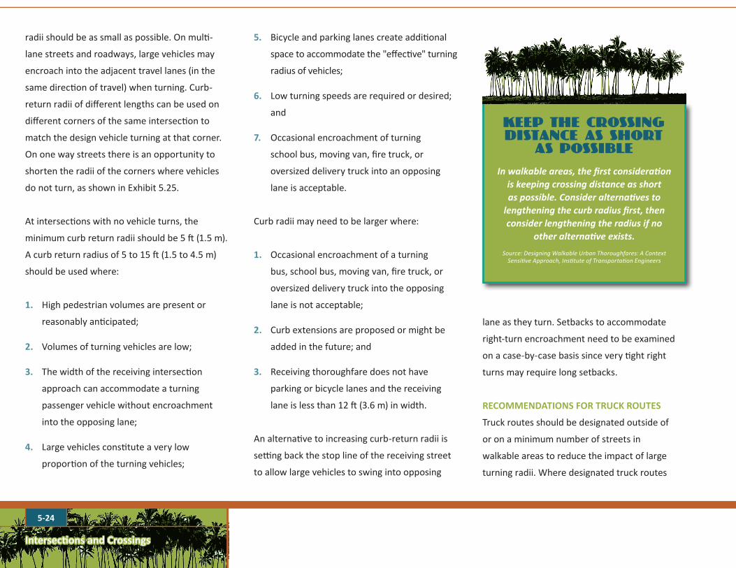
KEEP THE CROSSING DISTANCE AS SHORT
AS POSSIBLE
Inwalkableareas,thefirstconsiderationiskeepingcrossingdistanceasshortaspossible.Consideralternativestolengtheningthecurbradiusfirst,thenconsiderlengtheningtheradiusifno
otheralternativeexists.
Source: Designing Walkable Urban Thoroughfares: A Context Sensitive Approach, Institute of Transportation Engineers
Intersections and Crossings
5-25
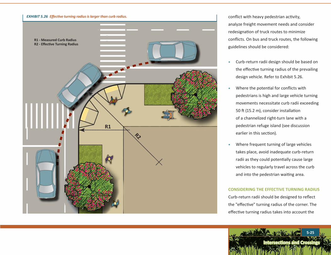
EXHIBIT5.26Effectiveturningradiusislargerthancurbradius.
R2
R1
R1 - Measured Curb RadiusR2 - Effective Turning Radius
conflict with heavy pedestrian activity,
analyze freight movement needs and consider
redesignation of truck routes to minimize
conflicts. On bus and truck routes, the following
guidelines should be considered:
• Curb-return radii design should be based on
the effective turning radius of the prevailing
design vehicle. Refer to Exhibit 5.26.
• Where the potential for conflicts with
pedestrians is high and large vehicle turning
movements necessitate curb radii exceeding
50 ft (15.2 m), consider installation
of a channelized right-turn lane with a
pedestrian refuge island (see discussion
earlier in this section).
• Where frequent turning of large vehicles
takes place, avoid inadequate curb-return
radii as they could potentially cause large
vehicles to regularly travel across the curb
and into the pedestrian waiting area.
CONSIDERING THE EFFECTIVE TURNING RADIUS
Curb-return radii should be designed to reflect
the "effective" turning radius of the corner. The
effective turning radius takes into account the
Intersections and Crossings
5-26
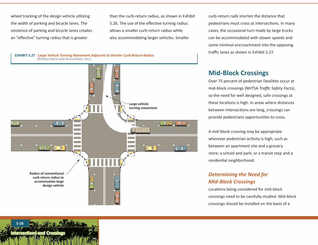
wheel tracking of the design vehicle utilizing
the width of parking and bicycle lanes. The
existence of parking and bicycle lanes creates
an "effective" turning radius that is greater
than the curb-return radius, as shown in Exhibit
5.26. The use of the effective turning radius
allows a smaller curb-return radius while
also accommodating larger vehicles. Smaller
curb-return radii shorten the distance that
pedestrians must cross at intersections. In many
cases, the occasional turn made by large trucks
can be accommodated with slower speeds and
some minimal encroachment into the opposing
traffic lanes as shown in Exhibit 5.27.
Mid-Block CrossingsOver 75 percent of pedestrian fatalities occur at
mid-block crossings (NHTSA Traffic Safety Facts),
so the need for well designed, safe crossings at
these locations is high. In areas where distances
between intersections are long, crossings can
provide pedestrians opportunities to cross.
A mid-block crossing may be appropriate
wherever pedestrian activity is high, such as
between an apartment site and a grocery
store; a school and park; or a transit stop and a
residential neighborhood.
DeterminingtheNeedfor Mid-BlockCrossings
Locations being considered for mid-block
corssings need to be carefully studied. Mid-block
crossings should be installed on the basis of a
EXHIBIT5.27LargeVehicleTurningMovementAdjacenttoShorterCurbReturnRadius(KimleyHornandAssociates,Inc.)
Large vehicle turning movement
Radius of conventional curb return radius to accommodate large
design vehicle
5-27
Intersections and Crossings
thorough engineering analysis if they are not
located at an existing stop sign, yield sign, or
traffic signal. Guidance for determining locations
for mid-block crossing installation is provided by
the ITE manual, Design and Safety of Pedestrian
Facilities and summarized in Exhibit 5.28.
DesignofMid-BlockCrossingsDesign treatments at mid-block crossings
are generally most effective when used in
combinations (e.g. marked crosswalks and signs).
As noted above in the section on Crosswalk
Markings, the presence of markings on four-lane
roads with an ADT of 12,000 or more and no other
pedestrian improvements has been associated with
a higher level of crashes, if no other treatments,
such as signs, flashing lights, signals, etc. are also
provided. For this reason, design treatments
should normally be used in combination at mid-
block crossings. These may include:
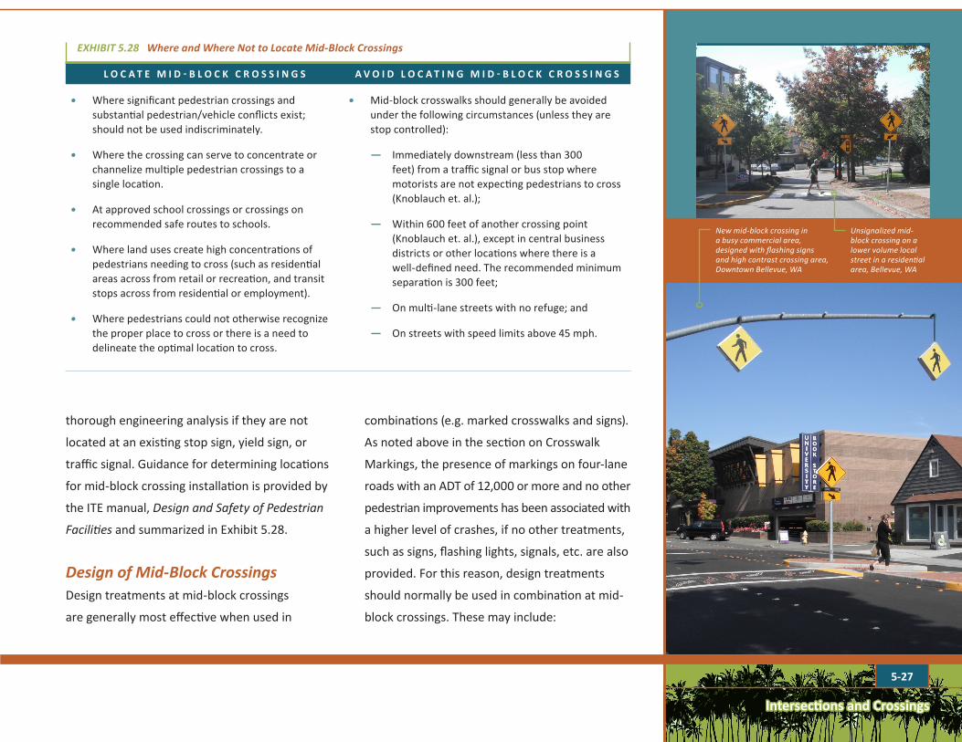
New mid-block crossing in a busy commercial area, designed with flashing signs and high contrast crossing area, Downtown Bellevue, WA
Unsignalized mid-block crossing on a lower volume local street in a residential area, Bellevue, WA
L O C A T E M I D - B L O C K C R O S S I N G S A V O I D L O C A T I N G M I D - B L O C K C R O S S I N G S
• Where significant pedestrian crossings and substantial pedestrian/vehicle conflicts exist; should not be used indiscriminately.
• Where the crossing can serve to concentrate or channelize multiple pedestrian crossings to a single location.
• At approved school crossings or crossings on recommended safe routes to schools.
• Where land uses create high concentrations of pedestrians needing to cross (such as residential areas across from retail or recreation, and transit stops across from residential or employment).
• Where pedestrians could not otherwise recognize the proper place to cross or there is a need to delineate the optimal location to cross.
• Mid-block crosswalks should generally be avoided under the following circumstances (unless they are stop controlled):
— Immediately downstream (less than 300 feet) from a traffic signal or bus stop where motorists are not expecting pedestrians to cross (Knoblauch et. al.);
— Within 600 feet of another crossing point (Knoblauch et. al.), except in central business districts or other locations where there is a well-defined need. The recommended minimum separation is 300 feet;
— On multi-lane streets with no refuge; and
— On streets with speed limits above 45 mph.
EXHIBIT5.28WhereandWhereNottoLocateMid-BlockCrossings
Intersections and Crossings
5-28
• Markings
• Stop or yield signs
• Signalization
• Pedestrian hybrid beacons
• Pedestrian actuated buttons
• Refuge islands
• Curb extensions
• Signs (sometimes with flashing lights) warning
motorists of the presence of pedestrians
Crossing design treatments and related
traffic control require careful consideration
and a traffic engineering analysis of existing
conditions on a project-by-project basis.
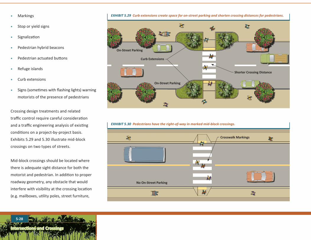
Exhibits 5.29 and 5.30 illustrate mid-block
crossings on two types of streets.
Mid-block crossings should be located where
there is adequate sight distance for both the
motorist and pedestrian. In addition to proper
roadway geometry, any obstacle that would
interfere with visibility at the crossing location
(e.g. mailboxes, utility poles, street furniture,
On-Street Parking
On-Street Parking
Curb Extensions
Shorter Crossing Distance
EXHIBIT5.29Curbextensionscreatespaceforon-streetparkingandshortencrossingdistancesforpedestrians.
Crosswalk Markings
EXHIBIT5.30Pedestrianshavetheright-of-wayinmarkedmid-blockcrossings.
No On-Street Parking
Intersections and Crossings
5-29
• Minimum length of 20 to 25 ft long
(6.1 m to 7.6 m)
• A wider area is needed to provide curb
ramps and a level area between the curb
ramps in the crossing region.
• Medians and pedestrian refuge islands shall
be 6 ft (1.8 m) minimum in length in the
direction of pedestrian travel. The crossing
refuge island shall contain a pedestrian
access route of 4 ft (1.2 m) width minimum
(PROWAG).
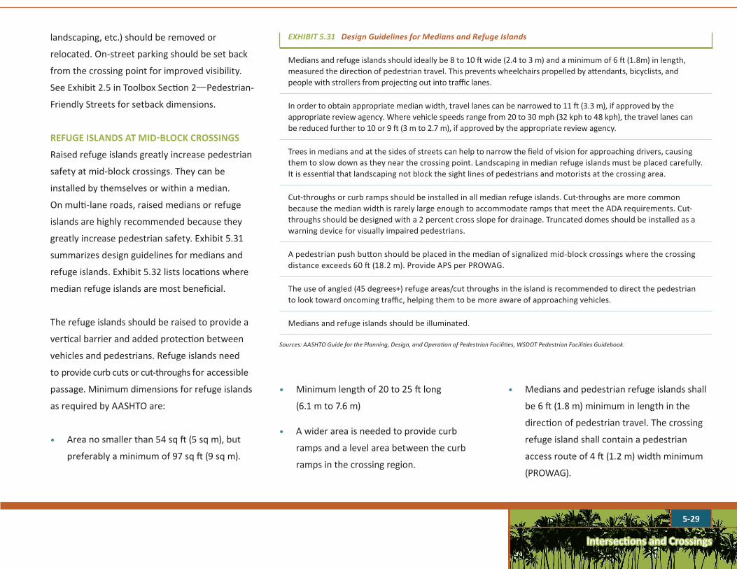
landscaping, etc.) should be removed or
relocated. On-street parking should be set back
from the crossing point for improved visibility.
See Exhibit 2.5 in Toolbox Section 2—Pedestrian-
Friendly Streets for setback dimensions.
REFUGE ISLANDS AT MID-BLOCK CROSSINGS
Raised refuge islands greatly increase pedestrian
safety at mid-block crossings. They can be
installed by themselves or within a median.
On multi-lane roads, raised medians or refuge
islands are highly recommended because they
greatly increase pedestrian safety. Exhibit 5.31
summarizes design guidelines for medians and
refuge islands. Exhibit 5.32 lists locations where
median refuge islands are most beneficial.
The refuge islands should be raised to provide a
vertical barrier and added protection between
vehicles and pedestrians. Refuge islands need
to provide curb cuts or cut-throughs for accessible
passage. Minimum dimensions for refuge islands
as required by AASHTO are:
• Area no smaller than 54 sq ft (5 sq m), but
preferably a minimum of 97 sq ft (9 sq m).
EXHIBIT5.31DesignGuidelinesforMediansandRefugeIslands
Medians and refuge islands should ideally be 8 to 10 ft wide (2.4 to 3 m) and a minimum of 6 ft (1.8m) in length, measured the direction of pedestrian travel. This prevents wheelchairs propelled by attendants, bicyclists, and people with strollers from projecting out into traffic lanes.
In order to obtain appropriate median width, travel lanes can be narrowed to 11 ft (3.3 m), if approved by the appropriate review agency. Where vehicle speeds range from 20 to 30 mph (32 kph to 48 kph), the travel lanes can be reduced further to 10 or 9 ft (3 m to 2.7 m), if approved by the appropriate review agency.
Trees in medians and at the sides of streets can help to narrow the field of vision for approaching drivers, causing them to slow down as they near the crossing point. Landscaping in median refuge islands must be placed carefully. It is essential that landscaping not block the sight lines of pedestrians and motorists at the crossing area.
Cut-throughs or curb ramps should be installed in all median refuge islands. Cut-throughs are more common because the median width is rarely large enough to accommodate ramps that meet the ADA requirements. Cut-throughs should be designed with a 2 percent cross slope for drainage. Truncated domes should be installed as a warning device for visually impaired pedestrians.
A pedestrian push button should be placed in the median of signalized mid-block crossings where the crossing distance exceeds 60 ft (18.2 m). Provide APS per PROWAG.
The use of angled (45 degrees+) refuge areas/cut throughs in the island is recommended to direct the pedestrian to look toward oncoming traffic, helping them to be more aware of approaching vehicles.
Medians and refuge islands should be illuminated.
Sources: AASHTO Guide for the Planning, Design, and Operation of Pedestrian Facilities, WSDOT Pedestrian Facilities Guidebook.

5-30
Intersections and Crossings
EXHIBIT5.32LocationsWhereRefugeIslandsareMostBeneficial
Wide, two-way streets (four lanes or more) with high traffic volumes, high travel speeds and large pedestrian volumes.
Wide streets where children, people with disabilities, or older adults cross regularly.
Wide, two-way intersections with high traffic volumes and significant numbers of crossing pedestrians.
Local and side streets where traffic volumes and flows create insufficient time to cross.
Minor access/local residential streets where they function both as traffic calming devices and street crossing aids.
Colorful stencil complements high contrast white lines of the crosswalk.
The crossing area is angled to orient pedestrians to the view of oncoming traffic.
EXHIBIT5.33Medianscreateanaturalplacetoprovideapedestrianrefugeislandinmid-block.
Curb Extensions shorten crossing distances.
Ladder bar markings make crosswalks highly visible.
Anglerefugeislandtowardoncomingtraffic
On-Street Parking
On-Street Parking

Intersections and Crossings
5-31
A raised refuge island with a cut through in a
“Z” form is the best practice as shown in Exhibit
5.33. It offsets the crosswalk so pedestrians
will be oriented towards oncoming traffic.
A walkway between split crossings can also
be provided, as shown in Exhibit 5.34. This
approach provides space for pedestrians
waiting to cross, and it also forces the
pedestrian to view oncoming traffic as they
walk from one crossing point to the next.
Railing can be installed to control pedestrian
crossing movements.
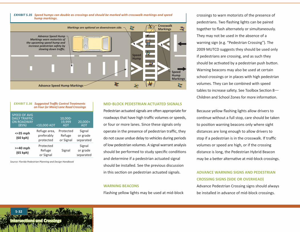
RAISED MID-BLOCK CROSSINGS
Raising a crossing to the same level as the
curb enhances pedestrian safety by making
pedestrians more visible and by functioning
as a speed hump or speed table, which
forces motorists to slow down. They provide
additional comfort to the pedestrian by
maintaining the grade from curb to curb.
Raised crossings should be accompanied by the
appropriate roadway markings as shown on
Exhibit 5.35. Advance speed hump markings are
designed to warn motorists of the upcoming
speed hump and may help alert them to the
presence of pedestrians as well.
SignalizationandSignsatMid-BlockCrossingsMid-block crossings may be signalized,
unsignalized, or use other techniques described in
this section to control roadway traffic. Signalization
should be designed and installed only on the
basis of a professional engineering study.
Exhibit 5.36 lists suggested traffic control
treatments for pedestrian crossings of four or
more lanes on streets and roadways. These
suggestions also apply to shared use paths.
EXHIBIT5.34AWellDesignedPedestrianRefugeataFully-SignalizedMid-BlockCrossing
30’ Pedestrian Walkway(9.1 m)
Railingcontrolspedestrianscrossingmovements.
Optional landscaping
PedestrianPush Button
Stop Bar
Signal
Pedestrian Push Button
Pedestrian Push Button
Signal
Stop Bar
Intersections and Crossings
5-32
MID-BLOCK PEDESTRIAN ACTUATED SIGNALS
Pedestrian actuated signals are often appropriate for
roadways that have high traffic volumes or speeds,
or four or more lanes. Since these signals only
operate in the presence of pedestrian traffic, they
do not cause undue delay to vehicles during periods
of low pedestrian volumes. A signal warrant analysis
should be performed to study specific conditions
and determine if a pedestrian actuated signal
should be installed. See the previous discussion
in this section on pedestrian actuated signals.
WARNING BEACONS
Flashing yellow lights may be used at mid-block
crossings to warn motorists of the presence of
pedestrians. Two flashing lights can be paired
together to flash alternately or simultaneously.
They may not be used in the absence of a
warning sign (e.g. “Pedestrian Crossing”). The
2009 MUTCD suggests they should be used only
if pedestrians are crossing, and as such they
should be activated by a pedestrian push button.
Warning beacons may also be used at certain
school crossings or in places with high pedestrian
volumes. They can be combined with speed
tables to increase safety. See Toolbox Section 8—
Children and School Zones for more information.
Because yellow flashing lights allow drivers to
continue without a full stop, care should be taken
to position warning beacons only where sight
distances are long enough to allow drivers to
stop if a pedestrian is in the crosswalk. If traffic
volumes or speed are high, or if the crossing
distance is long, the Pedestrian Hybrid Beacon
may be a better alternative at mid-block crossings.
ADVANCE WARNING SIGNS AND PEDESTRIAN
CROSSING SIGNS (SIDE OR OVERHEAD)
Advance Pedestrian Crossing signs should always
be installed in advance of mid-block crossings.
Markingsareoptionalondownstreamside.
Advance Speed Hump Markings
AdvanceSpeedHumpMarkingswarnmotoristsof
theupcomingspeedhumpandincreasepedestriansafetyby
slowingdowntraffic.
Speed Hump
SpeedHumpMarkings
Crosswalk Markings
EXHIBIT5.35Speedhumpscandoubleascrossingsandshouldbemarkedwithcrosswalkmarkingsandspeedhumpmarkings.
SPEED OF AVG DAILY TRAFFIC ON ROADWAY
(85%) <10,000 ADT
10,000-19,999
ADT20,000+
ADT
<=35 mph(60 kph)
Refuge area, preferably protected
Protected Refuge
or Signal
Signal or grade
separated
>=40 mph(65 kph)
Protected Refuge
or SignalSignal
Signal or grade
separated
Source: Florida Pedestrian Planning and Design Handbook
EXHIBIT5.36SuggestedTrafficControlTreatmentsonFour(orMore)LaneRoadCrossings

Intersections and Crossings
5-33
Placement of advance warning signs depends
on the speed of motor vehicle travel and other
conditions, such as available sight distance. Refer
to the 2009 MUTCD for sign placement criteria. To
avoid information overload and allow for improved
driver response, advance pedestrian warning
signs should not be mounted with other warning
or regulatory signs (except for a supplemental
distance sign or an advisory speed plate).
OtherDesignConsiderationsMid-block crossings should be well lit and may
require pedestrian lighting to supplement
existing street lighting.
Fences, barriers, signs, or sidewalk ramps can be
used at mid-block crossings and refuge islands
to channelize pedestrians to the crossing. Trees
and landscaping can also be used to enhance
and identify the crossing area, but care must
be taken to ensure that these do not obstruct
visibility at the crossing in any way.
Minimizing Pedestrian/Motor Vehicle Conflicts at Intersections and CrossingsThere are a variety of techniques to minimize
conflicts between pedestrians and motor
vehicles. These focus on maintaining sight
distances, restricting turning movements, on-
street parking restrictions, access management,
and signalization.
VisibilityandSightDistanceGood sight distance at intersections and mid-
block crossings improves pedestrian safety and
should be designed into roadway geometry.
Uncontrolled intersections and mid-block crossings
are of particular concern where inadequate sight
distance exists, because there is no control (stop
sign or signal) over the movements of vehicles
and pedestrians. Facilities such as signs, utility
poles, bus stops, benches, and other elements
are often added after design and construction of
an intersection, inhibiting driver and pedestrian
visibility. These elements should not be located in
areas that interfere with sight distances, if possible.
Exhibits 5.37 and 5.38 illustrate the area at an
intersection that should typically be kept clear
Clear travel area for pedestrians at intersections
30’
(9.1
m)
Thecleartravelareashouldbefreeofobstructionsthatcouldhinderpedestrianvisibility,suchasutilityvaults,benches,banners,etc.
EXHIBIT5.37ClearTravelArea
Follow local jurisdiction guidelines for sight distance triangles.
EXHIBIT5.38Adequatesightdistancemustbemaintainedatallintersections.
5-34
Intersections and Crossings
of obstructions. Refer to the HDOT standards or
local guidelines for sight distance calculations at
intersections and driveways.
Elements that obstruct the downward views of
high-seat position drivers (such as bus and truck
drivers) should also be avoided at intersections
(within the sight distance triangle area; see
Exhibit 5.38). This includes trees, signs, hanging
banners, and other elements.
Curb extensions at crossing points provide
space for pedestrians to stand in better view of
approaching vehicles, and on-street parking
can be placed closer to the crossing point
without affecting visibility of pedestrians. (See
Exhibit 5.29)
On-StreetParkingRestrictionsOn-street parking near pedestrian crossing
points can interfere with visibility. When cars
are parked too close to crossing points, they may
block the line of sight between the driver and
the pedestrian stepping off the curb to cross.
Refer to Toolbox Section 2—Pedestrian-Friendly
Streets for specific parking setback guidance.
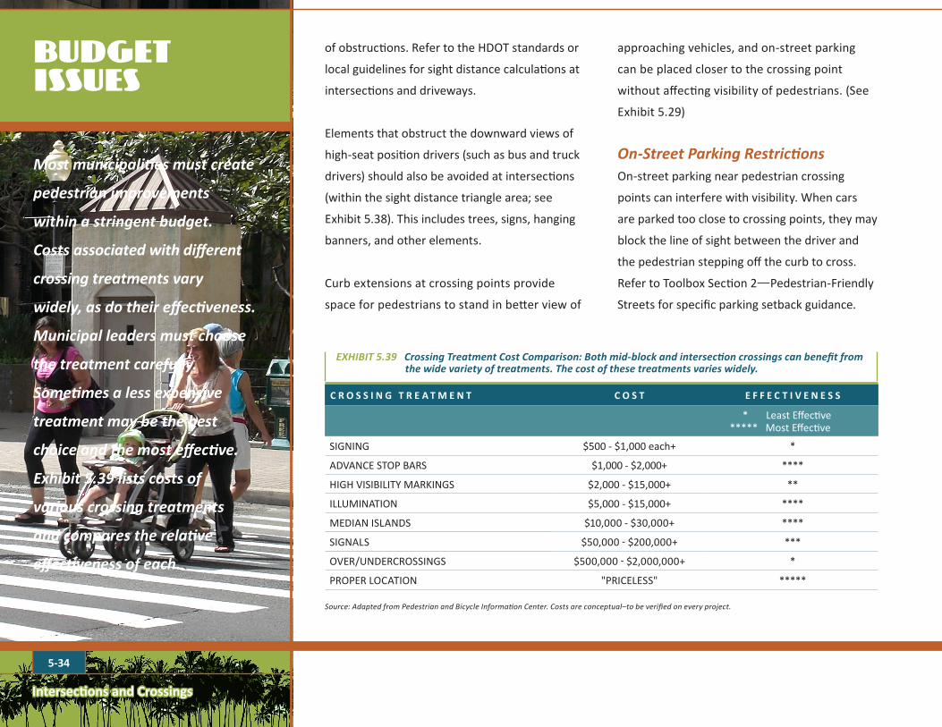
Mostmunicipalitiesmustcreate
pedestrianimprovements
withinastringentbudget.
Costsassociatedwithdifferent
crossingtreatmentsvary
widely,asdotheireffectiveness.
Municipalleadersmustchoose
thetreatmentcarefully.
Sometimesalessexpensive
treatmentmaybethebest
choiceandthemosteffective.
Exhibit5.39listscostsof
variouscrossingtreatments
andcomparestherelative
effectivenessofeach.
BUDGETISSUES
C R O S S I N G T R E A T M E N T C O S T E F F E C T I V E N E S S
* Least Effective ***** Most Effective
SIGNING $500 - $1,000 each+ *
ADVANCE STOP BARS $1,000 - $2,000+ ****
HIGH VISIBILITY MARKINGS $2,000 - $15,000+ **
ILLUMINATION $5,000 - $15,000+ ****
MEDIAN ISLANDS $10,000 - $30,000+ ****
SIGNALS $50,000 - $200,000+ ***
OVER/UNDERCROSSINGS $500,000 - $2,000,000+ *
PROPER LOCATION "PRICELESS" *****
Source: Adapted from Pedestrian and Bicycle Information Center. Costs are conceptual–to be verified on every project.
EXHIBIT5.39CrossingTreatmentCostComparison:Bothmid-blockandintersectioncrossingscanbenefitfromthewidevarietyoftreatments.Thecostofthesetreatmentsvarieswidely.
Intersections and Crossings
5-35
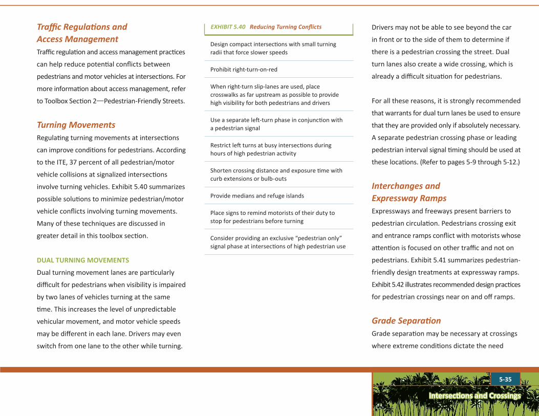
Design compact intersections with small turning radii that force slower speeds
Prohibit right-turn-on-red
When right-turn slip-lanes are used, place crosswalks as far upstream as possible to provide high visibility for both pedestrians and drivers
Use a separate left-turn phase in conjunction with a pedestrian signal
Restrict left turns at busy intersections during hours of high pedestrian activity
Shorten crossing distance and exposure time with curb extensions or bulb-outs
Provide medians and refuge islands
Place signs to remind motorists of their duty to stop for pedestrians before turning
Consider providing an exclusive “pedestrian only” signal phase at intersections of high pedestrian use
EXHIBIT5.40ReducingTurningConflictsTrafficRegulationsandAccessManagementTraffic regulation and access management practices
can help reduce potential conflicts between
pedestrians and motor vehicles at intersections. For
more information about access management, refer
to Toolbox Section 2—Pedestrian-Friendly Streets.
TurningMovementsRegulating turning movements at intersections
can improve conditions for pedestrians. According
to the ITE, 37 percent of all pedestrian/motor
vehicle collisions at signalized intersections
involve turning vehicles. Exhibit 5.40 summarizes
possible solutions to minimize pedestrian/motor
vehicle conflicts involving turning movements.
Many of these techniques are discussed in
greater detail in this toolbox section.
DUAL TURNING MOVEMENTS
Dual turning movement lanes are particularly
difficult for pedestrians when visibility is impaired
by two lanes of vehicles turning at the same
time. This increases the level of unpredictable
vehicular movement, and motor vehicle speeds
may be different in each lane. Drivers may even
switch from one lane to the other while turning.
Drivers may not be able to see beyond the car
in front or to the side of them to determine if
there is a pedestrian crossing the street. Dual
turn lanes also create a wide crossing, which is
already a difficult situation for pedestrians.
For all these reasons, it is strongly recommended
that warrants for dual turn lanes be used to ensure
that they are provided only if absolutely necessary.
A separate pedestrian crossing phase or leading
pedestrian interval signal timing should be used at
these locations. (Refer to pages 5-9 through 5-12.)
InterchangesandExpresswayRampsExpressways and freeways present barriers to
pedestrian circulation. Pedestrians crossing exit
and entrance ramps conflict with motorists whose
attention is focused on other traffic and not on
pedestrians. Exhibit 5.41 summarizes pedestrian-
friendly design treatments at expressway ramps.
Exhibit 5.42 illustrates recommended design practices
for pedestrian crossings near on and off ramps.
GradeSeparationGrade separation may be necessary at crossings
where extreme conditions dictate the need
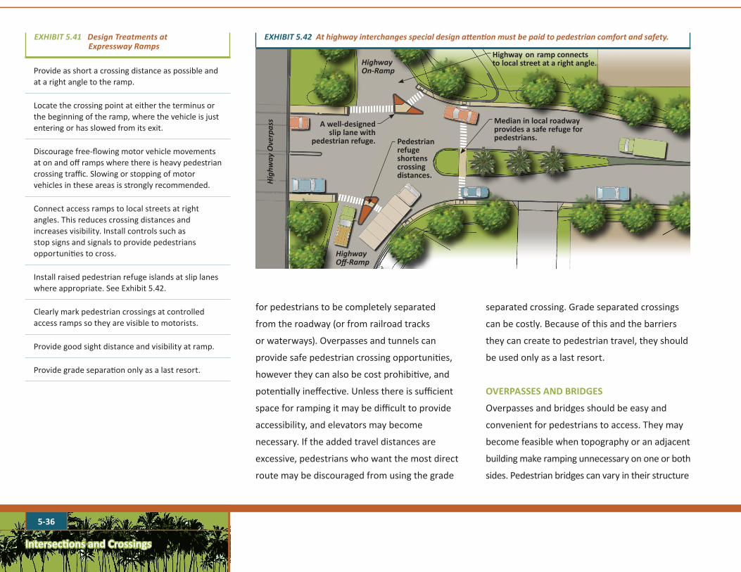
Intersections and Crossings
5-36
EXHIBIT5.41DesignTreatmentsatExpresswayRamps
for pedestrians to be completely separated
from the roadway (or from railroad tracks
or waterways). Overpasses and tunnels can
provide safe pedestrian crossing opportunities,
however they can also be cost prohibitive, and
potentially ineffective. Unless there is sufficient
space for ramping it may be difficult to provide
accessibility, and elevators may become
necessary. If the added travel distances are
excessive, pedestrians who want the most direct
route may be discouraged from using the grade
Provide as short a crossing distance as possible and at a right angle to the ramp.
Locate the crossing point at either the terminus or the beginning of the ramp, where the vehicle is just entering or has slowed from its exit.
Discourage free-flowing motor vehicle movements at on and off ramps where there is heavy pedestrian crossing traffic. Slowing or stopping of motor vehicles in these areas is strongly recommended.
Connect access ramps to local streets at right angles. This reduces crossing distances and increases visibility. Install controls such as stop signs and signals to provide pedestrians opportunities to cross.
Install raised pedestrian refuge islands at slip lanes where appropriate. See Exhibit 5.42.
Clearly mark pedestrian crossings at controlled access ramps so they are visible to motorists.
Provide good sight distance and visibility at ramp.
Provide grade separation only as a last resort.
A well-designed slip lane with
pedestrian refuge.
Highway on ramp connects to local street at a right angle.
Median in local roadway provides a safe refuge for pedestrians.
HighwayOff-Ramp
HighwayOn-Ramp
Highw
ayOverpass
EXHIBIT5.42Athighwayinterchangesspecialdesignattentionmustbepaidtopedestriancomfortandsafety.
separated crossing. Grade separated crossings
can be costly. Because of this and the barriers
they can create to pedestrian travel, they should
be used only as a last resort.
OVERPASSES AND BRIDGES
Overpasses and bridges should be easy and
convenient for pedestrians to access. They may
become feasible when topography or an adjacent
building make ramping unnecessary on one or both
sides. Pedestrian bridges can vary in their structure
Pedestrian refuge shortens crossing distances.
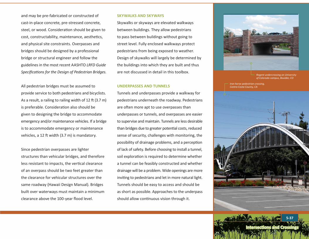
5-37
Intersections and Crossings
and may be pre-fabricated or constructed of
cast-in-place concrete, pre-stressed concrete,
steel, or wood. Consideration should be given to
cost, constructability, maintenance, aesthetics,
and physical site constraints. Overpasses and
bridges should be designed by a professional
bridge or structural engineer and follow the
guidelines in the most recent AASHTO LRFD Guide
Specifications for the Design of Pedestrian Bridges.
All pedestrian bridges must be assumed to
provide service to both pedestrians and bicyclists.
As a result, a railing to railing width of 12 ft (3.7 m)
is preferable. Consideration also should be
given to designing the bridge to accommodate
emergency and/or maintenance vehicles. If a bridge
is to accommodate emergency or maintenance
vehicles, a 12 ft width (3.7 m) is mandatory.
Since pedestrian overpasses are lighter
structures than vehicular bridges, and therefore
less resistant to impacts, the vertical clearance
of an overpass should be two feet greater than
the clearance for vehicular structures over the
same roadway (Hawaii Design Manual). Bridges
built over waterways must maintain a minimum
clearance above the 100-year flood level.
SKYWALKS AND SKYWAYS
Skywalks or skyways are elevated walkways
between buildings. They allow pedestrians
to pass between buildings without going to
street level. Fully enclosed walkways protect
pedestrians from being exposed to weather.
Design of skywalks will largely be determined by
the buildings into which they are built and thus
are not discussed in detail in this toolbox.
UNDERPASSES AND TUNNELS
Tunnels and underpasses provide a walkway for
pedestrians underneath the roadway. Pedestrians
are often more apt to use overpasses than
underpasses or tunnels, and overpasses are easier
to supervise and maintain. Tunnels are less desirable
than bridges due to greater potential costs, reduced
sense of security, challenges with monitoring, the
possibility of drainage problems, and a perception
of lack of safety. Before choosing to install a tunnel,
soil exploration is required to determine whether
a tunnel can be feasibly constructed and whether
drainage will be a problem. Wide openings are more
inviting to pedestrians and let in more natural light.
Tunnels should be easy to access and should be
as short as possible. Approaches to the underpass
should allow continuous vision through it.
Regent undercrossing on University of Colorado campus, Boulder, CO
Iron horse pedestrian crossing, Contra Costa County, CA

5-38
Intersections and Crossings
Useofskywalksmayleadto
alossofpedestrianactivity
atthestreetlevel,negatively
impactingtheretailbusinesses
andeconomicvitalityofthe
area.Whenskywalksarebeing
considered,waystoensure
thatstreetlevelretailwillstill
befullyaccessibleandinviting
topedestriansshouldbe
implemented.Inaddition,any
potentialviolationoftheview
corridormustbeavoided.
A NOTE OFCAUTION ABOUT SKYWALKS
Roundabouts can act as district gateways.
Pedestrians are not meant to cross into the
center of the roundabout, and the interior of the
roundabout can be designed to discourage this
type of crossing. The following techniques can
serve to discourage pedestrians from crossing
into the interior:
• Application of rails along the roundabout
legs to lead pedestrians and discourage
them from crossing into the interior. As the
radius, speed limits, and number of legs
increase, rails are more necessary.
RoundaboutsModern roundabouts are designed to slow traffic,
reduce delays, and handle higher traffic volumes.
Research has shown fewer pedestrian collisions
occur at roundabouts than at signalized or
unsignalized intersections. Single lane roundabouts
operate more safely than a two-way stop-
controlled intersection, and they are less expensive
to maintain than a signalized intersection. Single-
lane roundabouts are safer for pedestrians than
multi-lane roundabouts. Exhibit 5.43 illustrates a
roundabout design with pedestrian crossing areas.
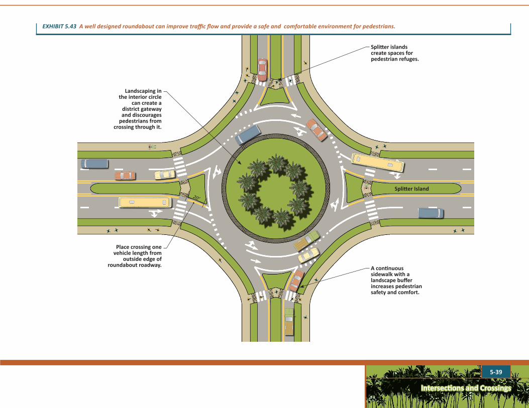
Intersections and Crossings
5-39
Place crossing one vehicle length from
outside edge of roundabout roadway.
Landscaping in the interior circle
can create a district gateway and discourages
pedestrians from crossing through it.
Splitter islands create spaces for pedestrian refuges.
A continuous sidewalk with a landscape buffer increases pedestrian safety and comfort.
20’
Splitter Island
EXHIBIT5.43Awelldesignedroundaboutcanimprovetrafficflowandprovideasafeandcomfortableenvironmentforpedestrians.
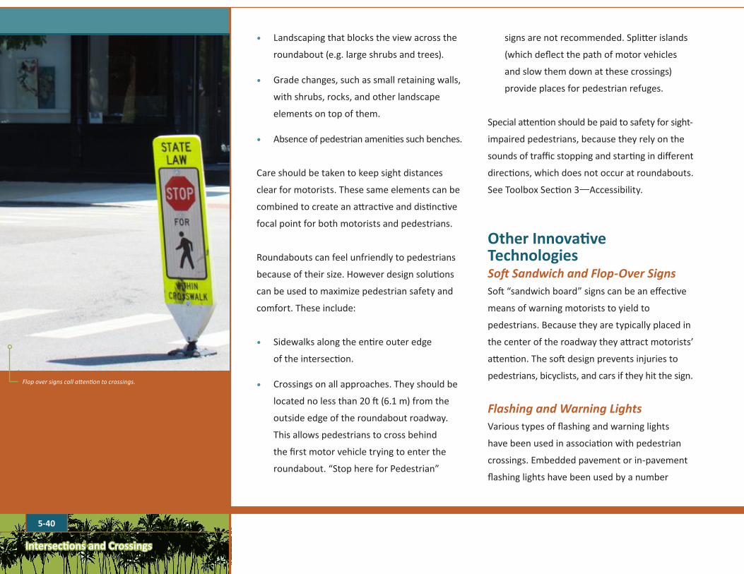
5-40
Intersections and Crossings
• Landscaping that blocks the view across the
roundabout (e.g. large shrubs and trees).
• Grade changes, such as small retaining walls,
with shrubs, rocks, and other landscape
elements on top of them.
• Absence of pedestrian amenities such benches.
Care should be taken to keep sight distances
clear for motorists. These same elements can be
combined to create an attractive and distinctive
focal point for both motorists and pedestrians.
Roundabouts can feel unfriendly to pedestrians
because of their size. However design solutions
can be used to maximize pedestrian safety and
comfort. These include:
• Sidewalks along the entire outer edge
of the intersection.
• Crossings on all approaches. They should be
located no less than 20 ft (6.1 m) from the
outside edge of the roundabout roadway.
This allows pedestrians to cross behind
the first motor vehicle trying to enter the
roundabout. “Stop here for Pedestrian”
signs are not recommended. Splitter islands
(which deflect the path of motor vehicles
and slow them down at these crossings)
provide places for pedestrian refuges.
Special attention should be paid to safety for sight-
impaired pedestrians, because they rely on the
sounds of traffic stopping and starting in different
directions, which does not occur at roundabouts.
See Toolbox Section 3—Accessibility.
Other Innovative TechnologiesSoftSandwichandFlop-OverSignsSoft “sandwich board” signs can be an effective
means of warning motorists to yield to
pedestrians. Because they are typically placed in
the center of the roadway they attract motorists’
attention. The soft design prevents injuries to
pedestrians, bicyclists, and cars if they hit the sign.
FlashingandWarningLightsVarious types of flashing and warning lights
have been used in association with pedestrian
crossings. Embedded pavement or in-pavement
flashing lights have been used by a number
Flop over signs call attention to crossings.

5-41
Intersections and Crossings
EXHIBIT5.44In-pavementwarninglightsmakepedestriansmorevisibleatnightorindark,cloudyconditions.
of jurisdictions throughout the United States
and are included in the 2009 MUTCD, Section
4N.02. They should be installed along the entire
length of the crosswalk between its outside
edge and ten feet from its outside edge. Refer
to the MUTCD for recommended flashing
rates, the number of lights to install and other
design parameters. Compared with other
types of warning devices, the effectiveness of
embedded pavement flashing lights is high.
Upon approach to a crosswalk with embedded
pavement flashing lights, drivers are more apt
to slow down and yield to pedestrians than
when drivers approach a crosswalk with another
type of lighted warning device. Also, compared
to a crosswalk with no warning device, drivers
are more likely to slow down and yield to
pedestrians when embedded pavement flashing
lights are in place. The device is particularly
effective at night. A study conducted in San
Jose, among other studies, confirmed the
effectiveness of embeddedflashinglights.See
Exhibit 5.44.
The MUTCD has issued interim approvals to many
jurisdictions across the United States for the
optional use of rectangular rapid flashing beacons
(RRFB). These devices are affixed to a pedestrian
crossing sign and placed at mid-block crossings.
Some of these devices use solar-powered, LED
illumination, which is energy efficient. Interim
approval allows interim use, pending official
rulemaking, of a new traffic control device, a
revision to the application or manner of use of
an existing traffic control device, or a provision
not specifically described in the MUTCD.
PuffinandPelicanCrossingsPuffin and Pelican crossings are in widespread
use in Great Britain and in some locations in
A pedestrian activating a Puffin crossing in Cumbria, England
Flashing warning light (Rectangular Rapid Flash Beacon—RRFB)
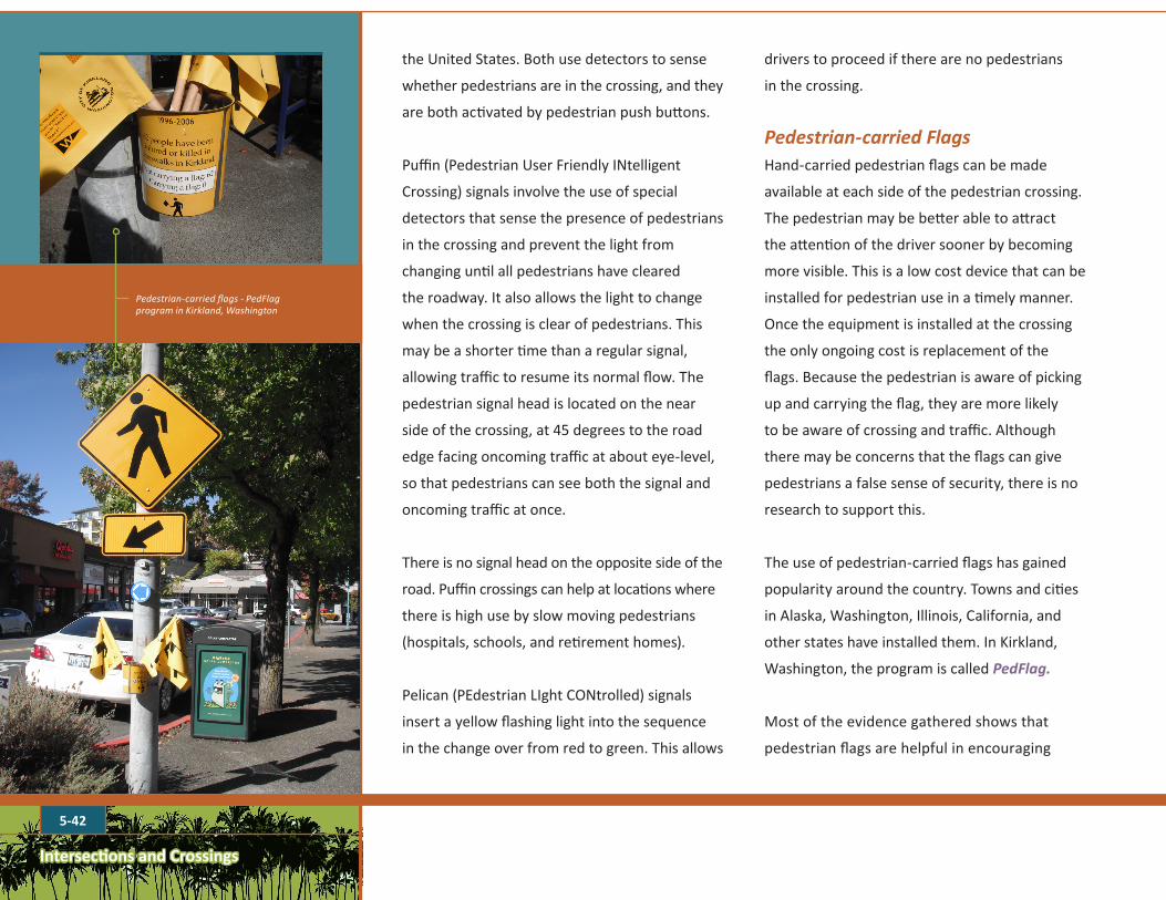
5-42
Intersections and Crossings
the United States. Both use detectors to sense
whether pedestrians are in the crossing, and they
are both activated by pedestrian push buttons.
Puffin (Pedestrian User Friendly INtelligent
Crossing) signals involve the use of special
detectors that sense the presence of pedestrians
in the crossing and prevent the light from
changing until all pedestrians have cleared
the roadway. It also allows the light to change
when the crossing is clear of pedestrians. This
may be a shorter time than a regular signal,
allowing traffic to resume its normal flow. The
pedestrian signal head is located on the near
side of the crossing, at 45 degrees to the road
edge facing oncoming traffic at about eye-level,
so that pedestrians can see both the signal and
oncoming traffic at once.
There is no signal head on the opposite side of the
road. Puffin crossings can help at locations where
there is high use by slow moving pedestrians
(hospitals, schools, and retirement homes).
Pelican (PEdestrian LIght CONtrolled) signals
insert a yellow flashing light into the sequence
in the change over from red to green. This allows
Pedestrian-carried flags - PedFlag program in Kirkland, Washington
drivers to proceed if there are no pedestrians
in the crossing.
Pedestrian-carriedFlagsHand-carried pedestrian flags can be made
available at each side of the pedestrian crossing.
The pedestrian may be better able to attract
the attention of the driver sooner by becoming
more visible. This is a low cost device that can be
installed for pedestrian use in a timely manner.
Once the equipment is installed at the crossing
the only ongoing cost is replacement of the
flags. Because the pedestrian is aware of picking
up and carrying the flag, they are more likely
to be aware of crossing and traffic. Although
there may be concerns that the flags can give
pedestrians a false sense of security, there is no
research to support this.
The use of pedestrian-carried flags has gained
popularity around the country. Towns and cities
in Alaska, Washington, Illinois, California, and
other states have installed them. In Kirkland,
Washington, the program is called PedFlag.
Most of the evidence gathered shows that
pedestrian flags are helpful in encouraging
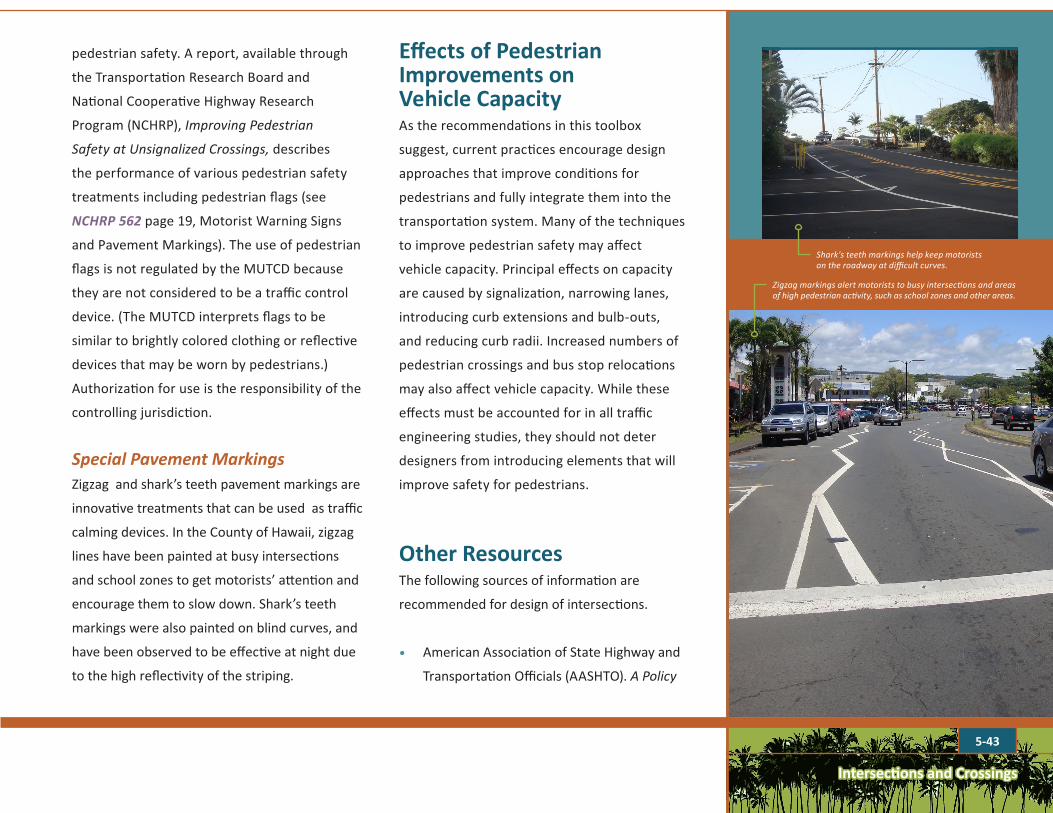
5-43
Intersections and Crossings
pedestrian safety. A report, available through
the Transportation Research Board and
National Cooperative Highway Research
Program (NCHRP), Improving Pedestrian
Safety at Unsignalized Crossings, describes
the performance of various pedestrian safety
treatments including pedestrian flags (see
NCHRP562page 19, Motorist Warning Signs
and Pavement Markings). The use of pedestrian
flags is not regulated by the MUTCD because
they are not considered to be a traffic control
device. (The MUTCD interprets flags to be
similar to brightly colored clothing or reflective
devices that may be worn by pedestrians.)
Authorization for use is the responsibility of the
controlling jurisdiction.
SpecialPavementMarkingsZigzag and shark’s teeth pavement markings are
innovative treatments that can be used as traffic
calming devices. In the County of Hawaii, zigzag
lines have been painted at busy intersections
and school zones to get motorists’ attention and
encourage them to slow down. Shark’s teeth
markings were also painted on blind curves, and
have been observed to be effective at night due
to the high reflectivity of the striping.
Effects of Pedestrian Improvements on Vehicle CapacityAs the recommendations in this toolbox
suggest, current practices encourage design
approaches that improve conditions for
pedestrians and fully integrate them into the
transportation system. Many of the techniques
to improve pedestrian safety may affect
vehicle capacity. Principal effects on capacity
are caused by signalization, narrowing lanes,
introducing curb extensions and bulb-outs,
and reducing curb radii. Increased numbers of
pedestrian crossings and bus stop relocations
may also affect vehicle capacity. While these
effects must be accounted for in all traffic
engineering studies, they should not deter
designers from introducing elements that will
improve safety for pedestrians.
Other ResourcesThe following sources of information are
recommended for design of intersections.
• American Association of State Highway and
Transportation Officials (AASHTO). A Policy
Shark's teeth markings help keep motorists on the roadway at difficult curves.
Zigzag markings alert motorists to busy intersections and areas of high pedestrian activity, such as school zones and other areas.

Intersections and Crossings
5-44
• Ewing, R., Pedestrian and Transit-Friendly
Design: A Primer for Smart Growth. R. Ewing
for Smart Growth Network in Florida, 1999.
http://www.epa.gov/smartgrowth/pdf/
ptfd_primer.pdf(May 2013).
• Federal Highway Administration. Guidelines
and Recommendations to Accommodate Older
Drivers and Pedestrians. FHWA Publication No.
FHWA-RD-01-051, May, 2001. http://www.
fhwa.dot.gov/publications/research/safety/
humanfac/01051/index.cfm(May 2013).
• Federal Highway Administration. Informational
Report on Lighting Design for Midblock
Crossings. 2008. www.fhwa.dot.gov/
publications/research/safety/08053/index.cfm
(May 2013).
• Federal Highway Administration. Manual on
Uniform Traffic Control Devices (MUTCD). 2009.
• Federal Highway Administration, Priorities and
Guidelines for Providing Places for Pedestrians
to Walk along Streets and Highways. 2000.
• Federal Highway Administration.
Roundabouts: An Information Guide, FHWA
publication #FHWA-RD-00-068. http://
www.fhwa.dot.gov/publications/research/
safety/00068/ (May 2013).
• Federal Highway Administration. Safety Effects
of Marked Versus Unmarked Crosswalks at
Uncontrolled Locations Final Report and
Recommended Guidelines, FHWA Publication
No.: FHWA-HRT-04-100, September 2005.
http://www.fhwa.dot.gov/publications/
research/safety/04100/(May 2013).
• Institute of Transportation Engineers,
Designing Walkable Urban Thoroughfares: A
Context Sensitive Approach. 2010.
• Institute of Transportation Engineers, Traffic
Engineering Council Committee TENC-5A-5,
Zegeer, Charles V. (Chair). Design and Safety
of Pedestrian Facilities, A Recommended
Practice of the Institute of Transportation
Engineers. 1998.
• National Complete Streets Coalition. www.
completestreets.org(May 2013).
• National Highway Traffic Safety
Administration. National Center for Statistics
and Analysis. Traffic Safety Facts. 2008
Data. Publication No. DOT HS 811 163.
on the Geometric Design of Highways and
Streets, 5th Edition. 2004.
• American Association of State Highway and
Transportation Officials (AASHTO). A Guide
for Achieving Flexibility in Highway Design.
2004.
• American Association of State Highway and
Transportation Officials (AASHTO). Guide
for Development of Bicycle Facilities, 4th
Edition. 2012.
• American Association of State Highway and
Transportation Officials (AASHTO). Guide
for the Planning, Design and Operation of
Pedestrian Facilities. 2004.
• American Association of State Highway
and Transportation Officials (AASHTO).
LRFD Guide Specifications for the Design of
Pedestrian Bridges.
• American Association of State Highway and
Transportation Officials (AASHTO). Roadside
Design Guide. 2002.
• American Planning Association, Wiley &
Sons, Inc. publishers. Planning and Urban
Design Standards. 2006.

Intersections and Crossings
5-45
http://www.walkinginfo.org/facts/docs/
PedTSF_2008.pdf(May 2013).
• Oregon Department of Transportation
and Oregon Department of Land Use and
Conservation. Transportation Growth
Management Program. Main Street—When
a Highway Runs Through It (Main Street
Handbook). 1999.
• Pedestrian and Bicycle Information Center.
www.walkinginfo.org(May 2013).
• Pedestrian Safety Guide and Countermeasure
Selection System, sponsored by the FHWA.
http://www.walkinginfo.org/pedsafe/
index.cfm (May 2013).
• Public Rights-of-Way Access Advisory
Committee (PROWAAC) to the US Access
Board. Special Report: Accessible Public
Rights-of-Way Planning and Design for
Alterations. http://www.access-board.gov/
prowac/alterations/guide.htm(May 2013).
• Seattle Right-of-Way Improvements Manual,
City of Seattle, Washington—online access:
http://www.seattle.gov/transportation/
rowmanual/manual/4_21.asp(May 2013).
• US Access Board Public Rights-of-Way
Accessibility Guidelines (PROWAG). Draft-
rulemaking in process. http://www.access-
board.gov/prowac/(May 2013).
• US Architectural and Transportation Barriers
Compliance Board: Accessible Rights-of-Way:
A Design Guide. 1999.


![Ulf Lorenz arXiv:1607.01714v2 [quant-ph] 11 Oct 2016 · Born-Oppenheimer (adiabatic) approximation, where the dynamics may be dominated by (avoided) crossings or conical intersections](https://static.fdocuments.net/doc/165x107/603539b581e3ed4b550f8e29/ulf-lorenz-arxiv160701714v2-quant-ph-11-oct-2016-born-oppenheimer-adiabatic.jpg)


