SECTION 1 - TERMS, DEFINITIONS, ABBREVIATIONS AND SYMBOLS
118
Special Conditions SC-1 of 118 Specification No. 3445 SECTION 1 - TERMS, DEFINITIONS, ABBREVIATIONS AND SYMBOLS (NOT USED)
Transcript of SECTION 1 - TERMS, DEFINITIONS, ABBREVIATIONS AND SYMBOLS

Special Conditions SC-1 of 118 Specification No. 3445
SECTION 1 - TERMS, DEFINITIONS, ABBREVIATIONS AND SYMBOLS
(NOT USED)

Special Conditions SC-2 of 118 Specification No. 3445
SECTION 2 - SCOPE AND CONTROL OF WORK
2.01 SPECIFICATIONS AND STANDARD PLANS The work to be done under this contract shall be performed in accordance with the following Specifications and Standard Plans: 1. Specification No. 3445. 2. Standard Specifications for Public Works Construction “Greenbook” 2012 Edition, including all supplements
thereto issued prior to bid opening date, exclusive of Part I. 3. State of California, Department of Transportation Standard Specifications for Traffic Signal Modifications and
Lane Markings, Painting and Signing, 2010 Edition. 4. Standard Plans for Public Works Construction, 2012 Edition related to traffic signal modifications, pavement
delineation and signing (including temporary conditions). 2.02 LOCATIONS OF WORK THOMAS BROS. NO. STREET NAME LIMITS MAP GUIDE (2003) 1. Chevy Chase Drive 541 W Chevy Chase Dr. 564 – D6 2. Glendale’s Public Works Yard 541 W Chevy Chase Dr. to Los Angeles St. 564 – D6 3. Garfield Avenue S. Los Angeles St. to Los Angeles St. 564 – D6 4. Los Angeles Street Public Works Yard to San Fernando Rd (SFRD) 564 – D6 5. San Fernando Road Los Angeles St. to Elk Ave at Colorado Blvd. 564 – C5 & D6 6. Colorado Boulevard SFRD to Colorado Bl., 830 feet w/o of SFR. 564 – C5 & D6 2.03 WORKING HOURS
For details, refer to General Conditions, Section 14.01 “Working Hours” and Special Conditions, Section 6.01 CONTRACTOR’s Schedule of Operation.
2.04 PERMITS The CONTRACTOR shall comply with all the requirements in the City of Glendale Excavation Permit Policy attached in Appendix B, except the CONTRACTOR shall not be required to pull a physical permit. The City has obtained or will obtain permits to enter for work to be performed on private property. The CONTRACTOR shall coordinate the work with the resident/business to accommodate any special needs and keep them informed of construction activities.
Special Conditions SC-3 of 118 Specification No. 3445
The City has obtained a permit for work to be performed within the jurisdiction of the City of Los Angeles, Department of Public Works Bureau of Engineering Excavation Permit. A copy of the permit is made a part of these Specifications and the CONTRACTOR shall comply with all of the requirements and provision of said permits. Copies of the permits shall be kept in the job site at all times. The City has obtained an approval and license agreement for work to be performed within the jurisdiction of the Southern California Railroad Authority/Metrolink Railroad (SCRRA/MTA) Right-of-Way underground crossing of the sewer pipeline. The CONTRACTOR shall obtain the required SCRRA/MTA Temporary Right-of-Way Permit, Form 6. The CONTRACTOR shall comply with all of the requirements and provision of said permits. Copies of the permits shall be kept in the job site at all times. The CONTRACTOR shall obtain the required Underground Tunneling Permit from the State of California, Department of Industrial Relations, Division of Occupational Safety and Health Administration (OSHA), Mining and Tunneling Unit. The OSHA Underground Soil Classification is attached in Appendix F. The CONTRACTOR shall obtain the required permit from the Los Angeles County Department of Public Works (LACDPW) NPDES Permit for discharging groundwater to the storm drain system owned by the LACDPW. A groundwater discharge permit for discharge into the storm drain system owned by the City of Los Angeles shall be in accordance with the City of Los Angeles Department of Water and Power Groundwater Discharge Permit. It is the Contractor’s responsibility to obtain a separate permit from the Los Angeles County Department of Public Works for the inspection of the above work. All costs involved in obtaining and complying with the said permits, including and obtaining the Los Angeles County inspection permit, coordination, payment of insurance, bonds and all other fees, shall be considered as paid for in the various related items of work and no additional compensation shall be made therefore. 2.05 MOBILIZATION
Mobilization shall consist of preparatory work and operations, including, but not limited to, those necessary for the movement of the personnel, equipment, supplies and incidentals to the Project site and for all other work and operations which must be performed or costs incurred prior to beginning work on the various contract items on the Project site. Payment for mobilization will be made as follows:
1. When the required submittals have been submitted and approved, 10% of the Contract Unite Price for mobilization will be made.
2. When the monthly progress payment estimate of the amount earned, not including the amount earned for mobilization, is 5 percent or more of the Contract Price, the total amount earned for mobilization shall be 50 percent of the Contract Unit Price for mobilization or 5 percent of the Contract Price, whichever is less, and said amount will be included in said estimate for payment.
3. When the monthly progress payment estimate of the amount earned, not including the amount earned for mobilization, is 10 percent or more of the Contract Price, the total amount earned for mobilization shall be 75 percent of the Contract Unit Price for mobilization or 7.5 percent of the Contract Price, whichever is less, and said amount will be included in said estimate for payment.
Special Conditions SC-4 of 118 Specification No. 3445
4. When the monthly progress payment estimate of the amount earned, not including the amount earned for mobilization, is 20 percent or more of the Contract Price, the total amount earned for mobilization shall be 95 percent of the Contract Unit Price for mobilization or 9.5 percent of the Contract Price, whichever is less, and said amount will be included in said estimate for payment.
5. When the monthly progress payment estimate of the amount earned, not including the amount earned for mobilization, is 50 percent or more of the Contract Price, the total amount earned for mobilization shall be 100 percent of the Contract Unit Price for mobilization or 10 percent of the Contract Price, whichever is less, and said amount will be included in said estimate for payment.
6. After completion of the Contract Work, the amount, if any, of the Contract Unit Price for mobilization in excess of 10 percent of the Contract Price will be included in final progress payment.
2.06 TRAFFIC CONTROL The CONTRACTOR shall order their operations, such that a minimum of one 10’ lane of traffic is open during non-working hours. When possible, the CONTRACTOR shall provide for two 10’ lanes during non-working hours. Changeable Message Signs will be required on arterial streets and at the discretion of the ENGINEER up to four weeks in advance of the work start. Refer to Special Conditions, Section 6.07 for additional Project Signage Requirements. Non-emergency vehicles may be delayed up to 60 minutes, if necessary. The CONTRACTOR shall provide all necessary signage and flaggers, as determined in the field. All costs involved in doing the above work shall be included in the various related items of work, and no additional compensation will be made therefore. 2.07 DAMAGE AND REPAIR TO EXISTING IMPROVEMENTS AND FACILITIES The repair or replacement of facilities damaged or removed by the CONTRACTOR located inside or outside the construction limits that are to remain as caused by the CONTRACTOR’s operations, shall be at his/her own expense to the satisfaction of the ENGINEER. The repair or replacement of the damaged work with new materials as necessary to restore the damaged areas or surfaces to a condition equal to and matching such conditions existing prior to the damage or start of this Contract shall be to the full satisfaction of the ENGINEER. During construction of the proposed improvements extreme care shall be exercised to protect existing public and private improvements such as existing curbs, sidewalks, driveways, walls, fences, planters, valves, lights, drainage structures, posts, signs, mailboxes, landscaping, plant life and vegetation, unless otherwise noted in the plans. When working in private property, the CONTRACTOR shall take due care that no existing improvement is damaged. Any markings left on the existing concrete walk, brick, carport, or any other surface improvements shall be removed to the satisfaction of the ENGINEER and property OWNER. All costs involved in restoration of existing improvements shall be included in the unit prices bid for the various related items of work and no additional compensation will be made therefore. A. Manhole and Vault Frame and Cover Adjustment to Grade
Special Conditions SC-5 of 118 Specification No. 3445
The CONTRACTOR, within 48 hours from completion of paving, shall dig out manhole frames and covers. In addition, no more than 48 hours shall elapse between the time a manhole or vault frame and cover is dug out from the newly laid asphalt and the time the finished surface of asphalt is placed around the frame that has been adjusted to fit the new finished surface grade.
The use of cast iron raising rings to adjust manhole frames will not be permitted. The CONTRACTOR shall notify other utility OWNERs at least 96 hours prior to any work in the vicinity of said facilities. They will raise their own manhole or vault covers to grade after final paving. Before paving over the covers, the CONTRACTOR shall cover them with either tarpaper or construction paper to facilitate separation of Asphalt concrete from the covers. In those sections where final street grades are not changed, the CONTRACTOR shall be responsible for paving up to and matching existing manhole and/or vault grades. This is not considered “manhole adjustment” and no additional compensation will be made therefore. All costs involved in complying with these requirements shall be included in the unit price bid for “Adjust Manhole Frame and Cover Set” of these Specifications, and no additional compensation will be made therefore.
2.08 DEWATERING
See Sections 12.05 Trench Dewatering and 12.06 Tunnel Groundwater Control for dewatering requirements.
2.09 CLEANUP AND DUST CONTROL Throughout all phases of construction, including suspension of work, and until the final acceptance, the CONTRACTOR shall keep the site clean and free from rubbish and debris. The CONTRACTOR shall also abate dust nuisance by cleaning, sweeping and sprinkling with water, or other means necessary. The use of water resulting in mud on public street shall not be permitted as a substitute for sweeping or other methods. At the discretion of the ENGINEER, the CONTRACTOR shall furnish and operate a self-loading motor sweeper with spray nozzles, to maintain streets affected by the CONTRACTOR’s operation in a condition of cleanliness acceptable to the City at all locations affected by the CONTRACTOR’s operations. These affected areas include all haul routes to and from the project and all areas of construction or restoration that have not been completed. The CONTRACTOR shall not proceed with any further work until the affected areas are cleaned to the satisfaction of the ENGINEER. Materials and equipment shall be removed from the site as soon as they are no longer necessary. Before the final inspection, the site shall be cleared of equipment, unused materials, and rubbish, so as to present a satisfactory clean and neat appearance. Care shall be taken to prevent spillage on haul routes. Any suck spillage shall be removed immediately and the area cleaned. Failure of the CONTRACTOR to comply with the ENGINEER's cleanup orders may result in an order to suspend work until the condition is corrected. No additional compensation will be allowed as a result of such suspension. All costs for cleanup and dust control shall be included in the unit price bid for the various related items of work and no additional compensation will be made therefore.
Special Conditions SC-6 of 118 Specification No. 3445
2.10 EARTHWORK Earthwork shall conform to Section 300 “Earthwork” of the Greenbook, as modified herein: A. Unclassified Excavation
Unclassified excavation shall include all native excavation within the roadway, and significant excavation in driveways and private property conforms, as shown on the project cross sections. The CONTRACTOR shall excavate and remove the earth to subgrade elevations shown on the plans. The work shall include excavation, storage of the material for use as roadway embankment where fill is needed, and/or off-haul of unsuitable or excess material. The quantity listed in the bid forms is a final pay quantity. No adjustment will be made in the quantity unless there is a change in the scope of work.
B. Unclassified Fill
Unclassified fill shall include the placement and recompaction of native material excavated as Unclassified Excavation, as shown on the project cross sections. The CONTRACTOR shall place and compact the earth to subgrade elevations shown on the plans. The work shall include hauling, grading and recompaction of the soil as roadway embankment where fill is needed. If the CONTRACTOR elects to off-haul the Unclassified Excavation and use Crushed Aggregate Base for fill, the equivalent tonnage of Crushed Aggregate Base will be deducted from the certified weight tags delivered to the project, and payment will be made at the unit price for Unclassified Fill. The quantity listed in the bid forms is a final pay quantity. No adjustment will be made in the quantity unless there is a change in the scope of work.
C. Over-Excavation of Subgrade
If needed, the CONTRACTOR shall remove wet or unsuitable subgrade material and replace it with crushed aggregate base, where designated by the ENGINEER. Payment for removing wet or unsuitable subgrade material shall be based upon the actual volume of earth removed and disposed of, and paid for at the unit price bid for “Over-Excavation of Subgrade” and no additional compensation will be made therefore.
D. Sub-Grade Preparation Sub-grade preparation shall conform to Section 301-1 of the Greenbook. The roadbed material shall be compacted to a relative compaction of 95% to a depth of 6-inches below the surface of the roadbed, as determined by ASTM D-1557-91.
During the excavation and compaction procedures, the CONTRACTOR shall take all necessary steps to insure the protection of all improvements, whether public or private, including utilities and their services, from any damage that could occur due to his/her operations.
See Payment Items Section of these Specifications for payment of these items.

Special Conditions SC-7 of 118 Specification No. 3445
2.11 MECHANICAL SLOPE STABILIZATION (Not Applicable)
2.12 PAVEMENT REMOVAL A. Header Cut & Surface Plane
Header Cut shall consist of the removal of existing Asphalt concrete pavement to a length and depth as shown on the plans. Measurement for payment of Pavement Removal (Header Cut) shall be linear feet of tapered 6-foot wide header cut. The permanent resurfacing shall be installed within 72 hours of the header cutting. No street shall be left unpaved over the weekend. Payment for header cutting shall be included in the unit price bid for “Pavement Removal, 6-Ft. Header Cut” of these Specifications and no additional compensation will be made therefore. Surface Plane shall consist of the removal of the existing Asphalt Concrete and/or Concrete Pavement to a length and depth as indicated on the construction plans. The permanent resurfacing shall be installed within 72 hours of the grinding. No street shall be left unpaved over the weekend. Payment for various Pavement Removals shall be included in the unit price bid for “Pavement Removal, Surface Plane“ in the Payment Items Section of these Specifications, and no additional compensation will be made therefore.
B. Pavement Removal (Reconstruction) Pavement Removal (Reconstruction) shall consist of the complete removal of existing Asphalt and/or Concrete pavement for reconstruction. A list of pavement depths based on coring is included on the plans. Measurement for payment of Pavement Removal (Reconstruction) shall be cubic yard, based on the area of removal per the plans and the actual depth of pavement encountered. Where complete pavement removal is required, the CONTRACTOR shall: 1. Provide adequate staging to maintain traffic flow on a paved surface; 2. Provide traffic control plans for approval prior to beginning work clearly showing construction staging
and temporary detours, as required; 3. Maintain streets such that no street is left unpaved over the weekend; and, 4. Provide permanent resurfacing within 72 hours of pavement removal, where traffic must travel on an
unpaved surface.
The permanent resurfacing shall be installed within 72 hours of the header cutting. No street shall be left unpaved over the weekend. Payment for pavement removal shall be included in the unit price bid for “Remove Concrete (Curb & Gutter)”, “Remove Existing Concrete Culvert”, and “Remove Concrete (Driveway)” in the Payment Item Section of these Specifications and no additional compensation will be made therefore.

Special Conditions SC-8 of 118 Specification No. 3445
C. Macadam Street
Macadam base (rock and oil) pavement exists up to 2 inches thick in localized areas and shall be completely removed. The quantity for of macadam base has been included in the pavement removal quantity and no separate payment will be made there for. Where macadam (rock and oil) pavement is encountered during header cutting/surface planing operations, the resurfacing procedure shall be modified as follows: The CONTRACTOR shall adjust the depth of header cut/surface plane as directed by the ENGINEER to minimize loosening or disturbing the rock base. The exposed macadam base shall then be rolled with a tandem steel wheel roller and capped immediately with a variable thickness of fine Asphalt Concrete pavement to hold the base until the final resurfacing course is placed. The cost of compaction to stabilize the macadam base shall be included in the unit price bid for “Pavement Removal” in the Payment Item Section of these Specifications, and no additional compensation will be made therefore.
D. Additional Or Reduced Pavement Removal The various existing pavement thickness shown in the plans are based on available information on file in the office of the City ENGINEER. Quantities shown in the bidding form tabulations are based upon the available pavement thickness information. Actual pavement thickness encountered in the project may vary as much as one inch (1”) from the thickness stated. If unusually thick pavements are encountered resulting in the average thickness varying more than one inch (1”), an adjustment in the volume of removals shall be made for extra compensation. The CONTRACTOR shall be paid for the additional pavement removal at the unit price bid for “Pavement Removal”, and no additional compensation will be made therefore. Where the existing pavement thickness is less than that shown on the plans resulting in reduced quantities for pavement removal, but additional excavation is required to make sub-grade, then the CONTRACTOR shall be paid for the additional excavation of sub-grade at the unit price bid for “Over Excavation of Sub-Grade”, and a corresponding reduction will be made to the quantity for pavement removal and credit will be given to the City calculated at the unit price bid for “Pavement Removal”, and no additional compensation will be made therefore.
2.13 CRUSHED MISCELLANEOUS BASE Crushed Miscellaneous Base shall conform to Section 200 “Rock Materials” of the Greenbook. Crushed Miscellaneous Base shall be used for leveling and making grade in the roadway area as necessary, and for backfill of over-excavated areas. At locations where Asphalt concrete pavements, curbs, gutters, cross-gutters, driveway aprons, and sidewalks are to be reconstructed, there may be instances where the proposed finish grades are higher than the existing. In these cases and as directed by the ENGINEER, the CONTRACTOR shall use crushed aggregate base to make grade. Crushed Miscellaneous Base will be measured based on the tonnage shown on vehicle certified weight tags. Weight tags from a certified scale shall be provided to the inspector on a daily basis.

Special Conditions SC-9 of 118 Specification No. 3445
All costs involved in complying with the above requirements shall be included in the unit price bid for various related items of work no additional compensation will be made therefore. 2.14 ROADWAY PAVEMENT Asphalt Concrete shall be in accordance with Section 203 “Bitumous Materials” and Section 302 “Roadway Surfacing” of the Greenbook. Recycled Asphalt Concrete Hot Mix (RAC) or Reclaimed Asphalt Pavement (RAP) as defined in section 203-7 of the Greenbook shall not be allowed for use in Asphalt Rubber Hot Mix (ARHM), but is acceptable in non-rubberized asphalt concrete mixes. The CONTRACTOR’S attention is directed to Sections 302-5.5 “Distribution and Spreading” and 302-5.6.2 “Density and Smoothness” of the Standard Specifications. The provisions of said Section shall be strictly adhered to. Fully automatic screeds will be required on this project. A fully automatic screed shall have a sled, 30-feet in length, on the side of the machine that will receive the next lift of asphalt concrete material. A joint maker, ski, etc., placed on the side of the machine to ride on the existing or previously constructed surface or lift of asphalt concrete material may be required as directed by the Engineer. Asphalt concrete shall be of the type shown on the plans unless modified by the Engineer in the field. Asphalt concrete patching needed and installed due to form work or other construction operations are not included in this quantity and the cost of such work should be included in the various related items of work requiring the patch. All costs involved in complying with the above requirements shall be included in the unit price bid for various related items of work no additional compensation will be made therefore. 2.15 COLD IN-PLACE RECYCLING (CIR) OF ASPHALT CONCRETE (Not Applicable)
2.16 COLD CENTRAL PLANT RECYCLING (Not Applicable)
2.17 ASPHALT RUBBER HOT MIX (ARHM)
Asphalt Rubber Hot Mix shall be in accordance with Section 302-9 “Asphalt Rubber Hot Mix (ARHM) of the Greenbook. The CONTRACTOR shall submit to the ENGINEER for approval, the type of Asphalt Rubber and the corresponding design mix to be used for this project. The CONTRACTOR shall only use the “Wet Process” in the manufacture of rubberized asphalt in accordance with Section 203-11 of the GREENBOOK. The completed asphalt rubber resurfacing shall be thoroughly compacted to be free from humps, depressions or irregularities. Any ridges, indentations or other objectionable marks left on the surface of the asphalt rubber shall be eliminated by roller or other means. The longitudinal and transverse joints shall be constructed to have a uniform finished surface throughout. The joints shall be constructed straight, neat, smooth, tight and seamless, irregular joints will not be accepted. Any finished surface with rugged appearance will be rejected. The CONTRACTOR shall provide the equipment for a hand held viscometer test per Section 203-11.4.1 for use by an independent testing company hired by the City.

Special Conditions SC-10 of 118 Specification No. 3445
A certificate of compliance for Asphalt Rubber binder shall be required from the materials supplier.
2.18 ROCK DUST BLOTTER (Not Applicable) 2.19 EMULSION-AGGREGATE SLURRY (Not Applicable)
2.20 ASPHALT RUBBER AGGREGATE MEMBRANE (ARAM) (Not Applicable)
2.21 MICROSURFACING (Not Applicable) 2.22 PORTLAND CEMENT CONCRETE FLATWORK This section shall cover all curbs, curb and gutters, sidewalks, curb ramps, driveways, driveway aprons, apronwalks, cross-gutters and other surface concrete flatwork, and shall conform to Section 303 “Concrete and Masonry Construction” of the Greenbook. A. Curb Size
The CONTRACTOR shall construct the new curb to match the adjoining existing curb, which may vary in size and shape on the various streets throughout the project.
B. P.C.C. Pavement Joints All new P.C.C. pavement (sidewalks, driveways, cross gutters, bus pads, etc.) shall have weakened plane joints or score lines that match existing adjacent patterns. At locations where there are no existing sidewalks, the weakened plane joints or score lines shall be constructed at regular intervals of 5 feet. For sidewalk repair installations less than 25-feet length, the longitudinal and transverse score lines shall match the adjacent walk scoring pattern. In Historic Districts on Royal Boulevard, Ard Eevin Avenue and Cottage Grove, the scoring pattern and finish shall match the existing pavement scoring and finishes in all cases. Typically, the existing scoring is a 2.5’ x 2.5’ grid.
C. Epoxy As directed by the ENGINEER in the field and at all locations where new Portland Cement Concrete pavement will be abutting directly against existing concrete structures, an epoxy (Sikadur 32, Hi-Mod or equal) shall be applied to the existing concrete mating surface prior to pouring of concrete. Product instructions on applying epoxy shall be followed strictly for effective application.
D. Rotary Finish In addition to concrete specified in the Greenbook and SSPWC, a rotary finish is required for all driveway aprons, alley aprons, and alley pavement; and gutters, cross gutters and sidewalks with over 5% grade. The gutters and cross gutters shall receive a “shiner” along the flow line.
E. Curb and Gutter Grades Where the existing street grade is 1.0% or greater, the new edge of gutter elevation shall be constructed 0.10’ above existing pavement elevation if determined to be feasible by the ENGINEER (No elevations or grades shall

Special Conditions SC-11 of 118 Specification No. 3445
be provided by the City). The CONTRACTOR’s surveyor shall prepare a profile design grade sheet and submit the same to the ENGINEER for approval prior to construction staking. At the discretion of the ENGINEER and at locations where driveway aprons and curb drains may be affected, the gutter hike-up may be varied from 0.12’ to 0.17’ maximum. Care shall be exercised by the CONTRACTOR and his Surveyor in setting the grades to assure that resulting curb faces shall not be less than 5” at any location. The top of depressed curbs within driveways shall be between 0.02’ to 0.08’ above the flow line. Wheelchair ramps shall have no curb face on the main ramp portion. Outlet elevations of curb drains shall be at least 0.02’ above the flow line. Where the existing curb face is less than 5”, the CONTRACTOR shall maintain the existing dimension, unless otherwise directed by the ENGINEER. Where the existing street grade is less than 1.0%, the City shall provide flow line or top of curb elevations only at grade breaks. The CONTRACTOR’s Surveyor shall be responsible for providing the necessary elevations at stations between grade breaks. Any questionable grades shall be resolved by the CONTRACTOR and the ENGINEER in the field before being set. All the above work is considered part of construction survey. All costs involved in doing the above work shall be included in the unit price bid for the various related items of work and no additional compensation will be made therefore.
G. Concrete Grinding and/or Shaving (Horizontal Sawcutting) Where the existing sidewalk is uplifted by tree roots 0.5-inch and more and 1.5-inch and less, if determined to be feasible by the Engineer the edge of the sidewalk shall be grinded, shaved, or saw cut to eliminate tripping hazards. Grinding, shaving, or sawcutting shall be Maximum of 8.33%, and have a smooth transition from edge to edge.
All cost involved in doing the above work will be paid by appropriated bid pay items.
2.23 DETECTABLE WARNING SURFACES FOR CURB RAMPS Detectable Warning Surfaces (raised truncated domes) shall be installed at new and existing ramps as shown on the plans. Detectable Warning Surfaces (DWS) shall comply with the Standard Plans for Public Works Construction, Caltrans Standard Plans, and Federal Americans with Disabilities Act requirements. DWS shall be black for residential streets (Federal Color No. 17038) and yellow for collector and arterial streets (Federal Color No. 33538). Manufacturers shall have a minimum of two years of experience in the manufacture and supply of DWS, and shall provide a written 5 year warranty for the product. The warranty shall include a certification of the CONTRACTOR completing the installation. The CONTRACTOR shall provide a written 2 year warranty for the DWS installation. The CONTRACTOR shall submit manufacturer’s product data, product samples, material test reports, installation instructions, and maintenance instructions. All materials shall be provided from the same manufacturer, or be approved in writing by the manufacturer. The City of Glendale has approved the following DWS for use within the City. The CONTRACTOR may submit other manufacturers for review and possible approval.
1. Armor-Tile (Embedded, Embedded-Replaceable and Surface-Mounted) 2. Armorcast (Embedded and Surface-Mounted) 3. Traffic Works 4. Access Tile
Special Conditions SC-12 of 118 Specification No. 3445
A. Existing Curb Ramps DWS for existing curb ramp installations shall be a flexible polyurethane mat with a maximum surface thickness of 0.12-inches (exclusive of the truncated domes). Installation shall be per manufacturer’s recommendations with a combination of adhesive and concrete screws. Existing concrete shall be thoroughly cleaned prior to installation. After installation, the perimeter shall be sealed or caulked per manufacturer recommendation. All adhesive shall be cleaned and trimmed, such that no adhesive is visible more than ¼” from the DWS. The DWS shall be covered with plywood until the adhesive has fully cured.
B. New Curb Ramps (installed as part of project)
DWS for new curb ramp installations shall be an epoxy polymer composition with flanges or ribs that embed into the concrete ramp a minimum of 2 inches. After installation, the DWS shall be free of any concrete splatter or other construction markings.
C. General Requirements The DWS shall have the following qualities: Water Absorption ASTM – D570 < 0.35% Impact Resistant ASTM – 5420 Slip Resistant Stain & Chemical Resistant Protected Against UV Deterioration
All costs involved in meeting the above requirements shall be included in the unit prices bid for “Install Detectable Warning Surface (New Curb Ramp)” and “Install Detectable Warning Surface (Existing Curb Ramp)” in the Payment Items Section of these Specifications, and no additional compensation will be made therefore. 2.24 TEMPORARY ADA ACCESS RAMPS Where directed by the Engineer, the Contractor shall install temporary curb ramps constructed of temporary Asphalt concrete to provide continuous sidewalk/parkway ADA access. The temporary ramps shall be constructed with a maximum slope of 8.33% on the main ramp and 10% on the “X”’s. After construction is completed in the area where the ramps have been installed, or when directed by the Engineer, the Contractor shall remove the temporary curb ramp, haul away and dispose of the temporary Asphalt concrete in a manner acceptable to the Engineer. The costs involved in the construction, maintenance and removal of the temporary curb ramps and for the haul away and disposal of the temporary Asphalt concrete to a dump site accepting such materials shall be included in the various related items of work and no additional compensation will be made therefore. 2.25 TEMPORARY ASPHALT CONCRETE PAVEMENT The Engineer shall determine the exact locations where temporary resurfacing will be needed. Immediately prior to permanent resurfacing, the Contractor shall remove, haul away and properly dispose of the temporary Asphalt concrete pavement separately to an approved dumping site accepting temporary asphalt concrete pavement. The Contractor shall not mix temporary asphalt concrete with permanent asphalt concrete, Portland cement concrete, earth or other materials that are to be removed from the site. At the end of each day’s paving, all vertical transverse construction joints shall be filled with cold mix asphalt concrete for a minimum horizontal distance, in direction of traffic, of 5 feet to provide a smooth transition for vehicular traffic. This transition shall be properly and continuously maintained until the final asphalt concrete course is placed.

Special Conditions SC-13 of 118 Specification No. 3445
All costs involved in complying with the above requirements shall be included in the unit price bid for various related items of work no additional compensation will be made therefore. 2.26 TRENCHING A. Trench Resurfacing - Permanent Asphalt and Portland Cement Concrete
Permanent trench resurfacing shall be placed upon completing two (2) blocks of pipe laying, unless otherwise approved by the ENGINEER. All permanent trench resurfacing shall be in accordance with City of Glendale Standard Plan No. 25-153, “Trench Resurfacing.” The permanent pavement thickness shall be the same thickness as the existing pavement, but not less than 4”. Where a section(s) of concrete pavement is removed to accommodate construction, restoration shall be to match existing conditions and shall start from a joint or score line and shall end in a joint or score line with a minimum replacement of 5-feet. All score lines shall be saw-cut prior to removal. The completed asphalt concrete resurfacing shall be thoroughly compacted to be free from humps, depressions or irregularities. Any ridges, indentations or other objectionable marks left on the surface of the asphalt concrete shall be eliminated by roller or other means. The longitudinal and transverse joints shall be constructed to have a uniform finished surface throughout. The joints shall be constructed straight, tight and seamless. Irregular joints will not be accepted. Any finished surface with a rugged appearance will be rejected. All traffic striping and pavement markings obscured, damaged, or removed during construction shall be permanently replaced in kind within 48 hours after final paving. All costs for Trench Resurfacing shall be included in the unit price bid for the various related conduits and trenching activities, and no additional compensation will be made therefore.
B. Trench Backfill Trench backfill shall comply with Section 306 “Underground Conduit Construction” of the Greenbook, except as modified herein. Trenches in arterial streets shall be backfilled with a 1-sack cement slurry mixture. Trenches on residential streets may be backfilled with native material or crushed miscellaneous base to the relative compaction specified unless otherwise required and stated differently on the plans. All costs for trench backfill shall be included in the unit price bid for the various related items of work and no additional compensation will be made therefore.
C. Protective Fencing for Open Trench Excavation
The CONTRACTOR shall install temporary protective fencing for open trench excavation where necessary for pedestrian and vehicular safety.

Special Conditions SC-14 of 118 Specification No. 3445
All costs for temporary protective fencing shall be included in the unit price bid for the various related items of work and no additional compensation will be made therefore.
D. Bracing of Excavations
The manner of bracing excavations shall conform to the Construction Safety Order of the Division of Industrial Safety. The Contractor is required to obtain a permit from the Office of the Division of Industrial Safety:
417 N. Azusa Avenue West Covina, CA 91791 Telephone: (626) 966-1166
The Contractor shall submit to the Engineer, for approval, a detailed plan showing the design of shoring, bracing, sloping, or other provisions to be made for worker protection from the hazard of caving ground during the excavation of trenches. If such plan varies from the shoring system standards established by the Construction Safety Orders, the plan shall be prepared by a registered Civil or Structural Engineer. The Contractor shall submit such plans prior to the beginning of excavation requiring shoring, and the Engineer shall have one (1) week to review said plans. No excavation requiring shoring shall begin prior to the review and acceptance of said plans by the Engineer. Trench shoring design should comply with the latest State of California Construction Safety Orders. Shoring up to 15 feet in depth should be designed for a Kw value of 35 pcf and shoring over 15 feet and up to 25 feet in depth should utilize 43 pcf. Solid shoring or other type of shoring capable of retaining loose material will be required, if necessary. Shoring design requirements shall be in accordance with the project geotechnical report prepared by Fugro Consultants, Inc., Chevy Chase Sewer Diversion Project, Glendale, California, dated June 2013, and enclosed in Appendix E. All costs involved in meeting the above requirements shall be included in the unit prices bid for the various related items of work and no additional compensation will be made therefore.
E. Removal of Temporary Striping and Restoration Of Permanent Striping From Trenching
The CONTRACTOR shall removal all the temporary traffic striping within 48 hours of the placement of permanent trench resurfacing. The striping shall be removed by sandblasting, grinding or other methods approved by the ENGINEER. All costs for removal of temporary traffic striping shall be included in the unit price bid for the various related items of work and no additional compensation will be made therefore.
F. Reconstruction of Concrete Curb and Pavements Where sections of curb, gutter, sidewalk or driveway are removed during the reconstruction of sewer mains or house connection laterals, restoration shall start from a joint or score line with a minimum replacement of five (5) feet. Score lines shall be sawcut prior to removal. All costs for restoration of existing concrete improvements shall be included in the unit price bid for the construction of sewer mains requiring such removals, and no additional compensation will be made therefore.
Special Conditions SC-15 of 118 Specification No. 3445
G. Trenching in City of LA
Improvements shown on Plan No. 3-1561 are located in the City of Los Angeles and City of Glendale. Trenching within the particular City shall follow the requirement of that specific City.
2.27 STORM DRAIN PIPE (Not Applicable) Construction of reinforced concrete storm drain pipe shall conform to Section 207 “Pipe” and Section 208 “Pipe Joint Types and materials” of the Greenbook. Reinforced concrete pipe shall be provided with a minimum D-load as shown on the plans. Stronger pipe may be substituted at the Contractor’s option, at no additional cost to the City. Prior to the construction of the new storm drain pipe, all crossings with existing utilities shall be potholed to verify potential conflicts. This potholing shall not be completed as part of the trenching process for the pipe installation. Full compensation for potholing shall be included in the unit price bid for the various storm drain pipes, and no separate payment will be made therefore. All costs involved in meeting the above requirements shall be included in the unit price bid for “X-Inch Reinforced Concrete Pipe”, and no additional compensation will be made therefore. See Payment Items Section of these Specifications for payment of this item. 2.28 CONCRETE STRUCTURES Construction of storm drain catch basins, manholes, junction structures, concrete collars, headwalls, storm water separator, and utility support/protection blanket shall conform to Section 303, “Concrete and Masonry Construction” of the Greenbook. Utility support/protection blankets shall be constructed to support and protect existing utilities in place per SPPWC Plan No. 224-2, at locations directed by the ENGINEER. Payment for Utility Support/Protection Blanket” will only be made if the item is constructed. The CONTRACTOR is responsible for normal support and protection of existing utilities. 2.29 PIPELINE SYSTEM REHABILITATION (LINING) (Not Applicable) 2.30 SANITARY SEWER PIPE See Sections 12.01 and 12.02 for sanitary sewer pipe. 2.31 STREET LIGHT RELOCATION Street Light Relocations shall conform the requirements of Section 307 “Street Lighting and Traffic Signals” of the Greenbook. The Contractor shall remove the existing base as part of the project. The contractor is responsible for rewiring the run as necessary. As part of the relocation, the contractor is responsible for constructing all necessary underground facilities, including conduits, pull boxes and foundations. A Street Light Pull Box shall be provided adjacent to each relocated street light. At the Contractor’s option, underground conduit may be Rigid Galvanized Conduit (RGC) or Polyvinyl Chloride (PVC) pipe. PVC requires the pipe zone be backfilled with 3-sack slurry concrete. RGC requires no encasement.

Special Conditions SC-16 of 118 Specification No. 3445
Payment for relocating the street lights shall be included in the unit price bid for “Relocate Existing Street Light” in the Payment Items Section of these Specifications and no additional compensation will be made therefore. 2.32 RESTORATION OF PLANTED AREAS All unpaved areas graded or disturbed during construction shall be planted with sod where possible or ground cover to match the existing plant life bordering said areas. The Contractor shall cover these areas with mulch and maintain them for 90 days. The planting shall be protected from damage due to the erosion or trespass by providing proper safeguards to prevent such damage. Planted areas adjacent to the proposed work which are disturbed by the Contractor, shall be planted with seed or ground cover to match the existing. Areas shall be covered with mulch or grass, where appropriate, watered and maintained for 15 days to the satisfaction of the Engineer. Payment for the above work, including grading, planting, sodding, and maintenance, shall be included in the unit price bid for the various related items of work and no additional compensation will be made therefore. 2.33 SPRINKLER SYSTEMS The Contractor shall remove portions of sprinkler systems in conflict with the new construction and provide for the immediate or within 24 hours, installation of a temporary irrigation/sprinkler system to water the remaining planted areas during construction. Before final acceptance of the work, the Contractor shall adjust/reconstruct the existing sprinkler systems including controllers and controller lines, if any, and where necessary, shall install additional new sprinkler heads, lines, valves and/or valve boxes to restore the sprinkler system to their original coverage less the new paved area. Any damage to existing plant life due to the Contractor’s delay in restoring the sprinkler systems or due to the improper restoration of the coverage area shall be repaired at the Contractor’s sole expense and to the satisfaction of the Engineer. All costs for restoration and/or adjustment of the sprinkler system shall be included in the unit prices bid for the various related items of work and no additional compensation will be made therefore. 2.34 TREE ROOT REMOVAL The CONTRACTOR’s attention is directed to the fact that at various locations, the construction of concrete curb and gutter, Portland cement concrete and Asphalt concrete pavements may require prior removal of tree roots that have initially damaged the existing pavements and curbs, or will potentially damage new pavements and curbs. A. Root Pruning
1. When pruning out selective roots, great care shall be given to retain as much root surface as possible, including sufficient buttress root dispersal around the radius of the tree.
2. No more than one-third (1/3) of the tree’s total root system shall be removed. 3. No root shall be cut back any closer than 18” from the base of a trunk, or 12” from where a trunk flare
breaks soil surface. 4. Offending roots shall be cut back four (4) inches away from new hardscape to the nearest node. 5. Pruning cuts shall be made clean and smooth with no crushing or tearing of the remaining root.
Should a root 2” or larger in diameter be inadvertently damaged while performing the work, surrounding soil shall be hand excavated and the root pruned back clean at the nearest undamaged portion.
Special Conditions SC-17 of 118 Specification No. 3445
B. Root Shaving
1. Root shaving is the removal of a small portion of a nonessential buttress root or general root with a diameter of four (4) inches or greater.
2. Roots will be shaved down to allow for at least two (2) inches of clearance between the root and the new hardscape.
3. No more than one-third (1/3) or a root’s diameter shall be shaved off. 4. Shaving cuts shall be made clean and smooth with no crushing or tearing of the remaining root.
Soil shall be backfilled immediately following pruning or shaving activity to minimize drying of the roots. Prior to pruning and/or shaving of tree roots, the CONTRACTOR must contact the City’s Urban Forester at
(818) 548-3950. Root removal and shaving is considered a part of the sub-grade preparation and shall be included in the unit
price bid for “Sub-Grade Preparation and Grading” of these Specifications and no additional compensation will be made therefore.
2.35 TREE PLANTING (Not Applicable) 2.36 HYDROSEEDING (Not Applicable) 2.37 CONSTRUCTION SURVEY
A. General
The Contractor shall provide construction survey for all the streets shown in Section 2.2 (LOCATIONS OF WORK) of these Special Conditions and including any street(s) which may be added to the contract, including office research of notes, plats or other necessary documents; marking removal limits; grade staking; tying and relocating utilities. All work shall be done to the satisfaction of the Engineer. The City of Glendale will provide copies of notes for all existing survey control points within the project limits. Prior to start of construction, the Contractor Shall provide for the perpetuation of all existing monumentation within the project limits. The Contractor shall notify the City of Glendale, in advance, in the event that any monumentation or witnesses to the monumentation should fall within any removal areas. The Contractor shall be liable for a back charge in an amount up to $2,000.00 per point obliterated or destroyed without notice or authorization from the City of Glendale. The Contractor shall provide, at the time of the pre-construction meeting, a tentative schedule of operations to allow the Contractor’s Surveyor sufficient time to set temporary construction control.
Any questionable grade, elevation, location or element of design shown on the plans shall be brought to the immediate attention of the Engineer in writing for clarification prior to construction.
The City reserves the right to verify all staking and monumentation for horizontal and vertical accuracy. The
allowable error shall not exceed 0.01 feet vertically or horizontally. Any staking found to exceed allowable error shall be reset at the sole expense of the Contractor and no additional compensation will be made therefore. In cases where the Contractor is unable to place a monument, such as conflicts with underground utilities, the Contractor shall notify the Engineer for review, confirmation, and approval of the omission.

Special Conditions SC-18 of 118 Specification No. 3445
All work described in this Section shall be done by or under the direction of a Professional Land Surveyor or a Registered Civil Engineer authorized to practice Land Surveying in the State of California herein referred to as “Surveyor”.
The Contractor shall provide for the perpetuation and reestablishment of all survey markers (Centerline ties,
property corners, survey well monuments, etc.) as part of the contract including filing documents (corner records, tie sheets, etc. with the County of Los Angeles.
B. Staking The Contractor’s Surveyor shall have all the necessary tools, materials, personnel available at the job site for
setting blue, yellow and red top hubs at the time that they are set, and shall adequately reference all such stakes by setting hubs three (3) inches below subsurface.
The Surveyor shall have the option of establishing line and grade either by setting stakes to finished grade,
marking the cuts and fills on the pavement, or referring to stakes, spikes, drill holes, chisel cuts, etc., on a grade sheet. Normally, stakes will be set and stationed by the Surveyor for rough grade, curbs, headers, sewers, storm drains, and structures and a corresponding cut or fill to finished grade (or flow line) indicated on a grade sheet. If the Surveyor elects to set stakes to the finished grade, the top of these stakes will be colored with blue crayon or paint. All elevations will be established with a Surveyor’s level or Theodolite.
For street improvements, the Surveyor will establish rough grade elevations at 50-foot intervals along the
street. After completion of the rough grading, he/she will establish elevations for curb or pavement headers. An elevation for pavement will be established at all points indicated by elevations shown on the plans. Elevations will be established at 25-foot intervals on the centerline and at all grade changes. For resurfacing over existing pavement or constructing 2 or 3 course bituminous pavement, the Surveyor will paint data on the surface of the existing pavement and/or base course and each lift to indicate the fill to finished grade at such locations and intervals as to provide adequate control for laying the wearing surface course to finished grade. Flow line elevations will be established by the Surveyor at all changes in grade and at 25-foot intervals when the grade is greater than 0.50% and at 10-foot intervals for grades of 0.50% or less. For flow lines adjacent to curbs on grades 1.0% or over, when the curb is new and has a uniform curb face, flow line elevations will not be set on existing curbs, the grade of which may be irregular, grade points will be set at all changes in grade and at 25-foot intervals. Sufficient flow line elevations will be set to facilitate the construction of warped pavement sections or for special drainage conditions.
For integral curb and gutter, blue tops for the flow line will not be set but curb elevations shall be established
at all changes in grade and at 25-foot intervals when the grade is more than 0.50% and at 10-foot intervals when the grade is 0.50% or less. In the case of integral curb and gutter with a varying curb face, grade sheets will show cuts and fills to the top of the curb or to the flow line and indicate the required curb face.
For sewers and storm drains, the Surveyor will establish elevations at 25-foot intervals along the main line, at
all grade change points indicated on the plans, at inlets and outlets of structures and at the upper ends of house connections and laterals. Normally, elevations for narrow trenches will be established by means of offset stakes and a grade sheet giving cuts from such stakes will be issued. When determined necessary, blue top hubs will be set in the trench for line and grade.
Distances and measurements, except elevations and structural dimensions, are given and made on horizontal
planes.
Special Conditions SC-19 of 118 Specification No. 3445
Copies of all grade sheets, cut sheets and notes shall be provided to the ENGINEER the day after survey work is performed.
C. Payment
All costs involved in meeting the above requirements shall be included in the unit prices bid for the various related items of work and no additional compensation will be made therefore.

Special Conditions SC-20 of 118 Specification No. 3445
SECTION 3 - CHANGES IN WORK 3.01 ADDITION OR DELETION OF WORK The City may change the Plans, Specifications, character of the work, or quantity of work as indicated in the contract documents, provided the total arithmetic dollar value of all such changed, both additive and deductive, does not exceed 25 percent of the Contract Price. Should it become necessary to exceed this limitation, the change shall be agreed upon to proceed with the Change Order.
In the event work is added or deleted to the Contract, basis of payment for such addition or deletion shall be per the Contract Unit Price as indicated in the Bidding Form. All amounts shall be considered as representing the total in-place costs to include but not limited to costs for construction survey, signage and barricading, notification to adjacent businesses and residents, equipment, clean-up and protection of adjacent facilities, labor, material, overhead taxes, insurance, bonds, profit and other incidental and appurtenant work necessary for the complete improvement as shown or indicated in the plans and specifications.
Special Conditions SC-21 of 118 Specification No. 3445
SECTION 4 - CONTROL OF MATERIALS 4.01 CONSTRUCTION LIMITS AND UNAUTHORIZED REMOVALS The exact limits of removals for construction or reconstruction of Asphalt concrete pavements, Portland cement concrete gutters, driveway aprons, curbs and sidewalks will be marked in the field by the Contractor’s Surveyor in accordance with the project plans and approved by the Engineer prior to the start of saw cut and/or removal operations by the Contractor. Should the Surveyor encounter any questionable removals in the field, he/she will confer with the Engineer in the field to verify the actual limits of removal. The actual limits of paving of each street and cross street will be marked in the field by the Contractor’s Surveyor and approved by the Engineer. Should the Surveyor encounter any questionable paving limits in the field, he/she will confer with the Engineer in the field to verify the actual limits of street paving. The Contractor shall perform his/her saw cutting operations in conformity with NPDES requirements (General Condition, Section 2.16 Water Pollution Control) and Section XI, Subsection C of the City of Glendale, Public Works Division’s Excavation Permit Policy, which states, “Pavement saw cuts shall not extend beyond the boundaries for that section of pavement that is to be removed. Over cutting of pavement removals will not be accepted.” Should the Contractor over cut Portland Cement Concrete pavements, and curb, then he/she shall extend the removal to the next score line or expansion joints to include that portion of the cut Portland Cement Concrete pavement or curb. The costs involved in replacing the additional concrete pavements or curb shall be at the Contractor’s sole expense. If the Contractor over cuts Asphalt Concrete pavement, then the Engineer shall determine the new limits of removal to include the areas where the Contractor has over cut. The additional costs for pavement removal, sub-grade preparation and grading shall be at the Contractor’s sole expense. The Engineer shall calculate the additional Asphalt Concrete pavement tonnage that would be incurred by the additional removal area and the amount shall be deducted from the certified weight tickets submitted to him/her during the paving operations. Any unauthorized removals (improvements or other items not designated for removal) resulting from Contractor’s and/or his/her Surveyor’s operations shall be replaced at the Contractor’s sole expense.

Special Conditions SC-22 of 118 Specification No. 3445
SECTION 5 - UTILITIES 5.01 EXISTING SUBSTRUCTURES The CONTRACTOR is advised that the following substructures may exist at various locations within the immediate vicinity of the project limits: Contact No. or Person Structure Type OWNER for Exact Location Sprinkler System Adjacent Property OWNER Resident Traffic Signal City of Glendale 818) 548-3960 Facilities Public Works Department
Sewer and Storm City of Glendale (818) 548-3945 Drain Facilities Public Works Department Storm Drain Facilities Los Angeles County (626) 458-3129 Public Works Department Water lines, valves, Glendale Water & Power Department (818) 548-2062 meters, manholes Water Services Division Water lines, valves, Crescenta Valley Water (818) 248-3925 meters, manholes District Water lines, valves, Metropolitan Water District (213) 217-7726 meters, manholes of Southern California (818) 832-2110 Electric conduits, Glendale Water & Power Department (818) 548-3923 pullboxes, vents Electrical Services Division Street lights, Glendale Water & Power Department (818) 548-3921 conduits, pullboxes Electrical Services Division Gas service lines Southern California (818) 701-3316 meters and valves Gas Company (323) 881-3530 Telephone conduits, AT&T (800) 422-4133 and manholes Cable TV Conduits Charter Communications (818) 547-5013 City Owned Parks, Recreation & (818) 548-3734 Irrigation Systems Community Service Department It shall be the responsibility of the CONTRACTOR to determine the exact location of all substructures including their service connections prior to commencing work. The CONTRACTOR shall repair at his/her sole expense, any damage to any existing substructure caused by his/her operations. At the OWNER’s option, said repair may be made by the OWNER, and the actual cost thereof shall be paid by the CONTRACTOR.

Special Conditions SC-23 of 118 Specification No. 3445
5.02 UTILITY LOCATIONS The CONTRACTOR shall determine the location and depth of all utilities, including service connections, which have been marked by the respective OWNERs and which may affect or be affected by his/her operations. The CONTRACTOR shall perform this work in a timely manner to allow the respective OWNERs sufficient time to relocate the interfering utilities. The CONTRACTOR shall also note that field markings made by various utilities using Underground Service Alert (USA) shall be considered as identified utilities even when they are not shown on the plans. Two (2) working days after the conclusion of the CONTRACTOR’s work at each site/location all remaining field markings related to the project made by various utilities using USA shall be removed by the CONTRACTOR as directed by the ENGINEER. Full compensation for locating utilities and removal of markings shall be included in the unit prices bid for the various related items of work and no additional compensation will be made therefore. Utility relocation work shall be completed at least 30 days prior to the start of work requiring the relocated utility to be moved. The CONTRACTOR shall provide adequate scheduling to allow for the utility relocation work to be completed before moving onto the site. 5.03 LOCATION AND PROTECTION OF UNDERGROUND HAZARDOUS UTILITIES The CONTRACTOR is hereby notified that, as specified in these Special Conditions, there are underground utilities within the construction area, which may be potentially hazardous if damaged. A hazardous substance shall be defined as one having the potential for an immediate disaster, such as, but not limited to gasoline, high-voltage electricity, fuel oil, butane, propane, high-pressure natural gas, chlorine or other chemicals. Abandoned or inoperative utilities designed to carry hazardous substances and unidentified or unknown utilities shall be considered hazardous until determined otherwise. Whenever the CONTRACTOR is directed by the ENGINEER to tap those lines, the CONTRACTOR shall provide personnel specialized in this work and payment thereof will be made under the Extra Work provisions of these specifications. During all excavation operations, the CONTRACTOR will be required to exercise extreme caution and protect these utilities from damage.
The CONTRACTOR shall notify the OWNERs at least 96 hours prior to any excavation in the proximity of those lines. Prior to completing the potholing, the CONTRACTOR shall accurately determine the horizontal locations and depths of their potentially hazardous lines as follows: 1. The CONTRACTOR shall not trench or excavate within the area where a utility known to carry a hazardous
substance exists until its OWNER is present and its location have been determined the OWNER. The intervals between pot holes or location points shall be sufficient to determine the exact location of the line and shall not exceed the distance set forth as follows:
a. Excavation for highway or street construction: The utility shall be located at intervals not greater than 25 feet for lines up to 8 inches in diameter, 50
feet for lines of 8 inches to 24 inches in diameter and 100 feet for lines greater than 24 inches in diameter.
b. Clearance: If it is determined that the horizontal or vertical clearance between the utility known to carry
hazardous substances and the construction limit is less than 12 inches (18 inches if scarifying), the

Special Conditions SC-24 of 118 Specification No. 3445
CONTRACTOR shall confer with its OWNER. Unless the OWNER elects to relocate the line or take it out of service, the CONTRACTOR shall not excavate until the line has been completely exposed by its OWNER within the limits of construction.
2. Once the physical location of the utility known to carry hazardous substances has been determined, the
CONTRACTOR, in cooperation with and with the concurrence of the utility OWNER, shall determine how to protect and/or support the utility from damage before proceeding with this work. The OWNER of the utility has the right to support and/or protect its utility at the sole expense of the utility OWNER.
3. The CONTRACTOR shall notify the contracting agency, the public agency maintaining records for that jurisdiction and the OWNER, if known, whenever previously unidentified or unknown underground utilities are encountered so that the location can be accurately established and made a part of the permanent sub-structure records.
Full compensation for complying with any or all of the above requirements shall be considered as included in the price bid for various related items of work, and no additional compensation will be made therefore. 5.04 EXISTING CITY’S UTILITIES/FACILITIES The Contractor shall uncover existing utilities facilities (pull boxes, conduits, fire hydrants, water meters and valves) in conflict with the proposed improvements and notify the following agencies 48 hours prior to start of construction of various items for their locations. 1. Water facilities Glendale Water & Power (GWP) (818) 548-2062 2. Electrical facility GWP (818) 548-3921 3. Fiber Optic GWP (818) 548-3923 4. Street Lighting GWP (818) 548-4877
5. Traffic signal facilities – Traffic Section (818) 548-3945 6. Crescenta Valley Water District (818) 248-3925
The Contractor will be responsible for protecting and maintaining in place the existing conduits. Care should be taken during removal operations to determine the exact location and depth of the conduit. Any damage caused by the Contractor must be reported immediately such that repairs to water facilities can be made by their respective owner. Repairs to traffic signal facilities shall be done only by a licensed Traffic Signal Contractor licensed to do work in the City of Glendale. All costs for the repairs shall be borne by the Contractor and at no cost to the City. Relocation of water or traffic signal facilities interfering with the proposed work shall be done by the Glendale Water & Power Department, Engineering Division, or Crescenta Valley Water District at no cost to the Contractor unless otherwise shown on the plans. A. Existing Electric Facilities
1. Power Poles
A minimum of five feet of undisturbed soil shall be maintained around each power pole. Excavation in the vicinity of any power pole shall be adequately and properly shored to prevent the power pole from being undermined.

Special Conditions SC-25 of 118 Specification No. 3445
All overhead facilities must maintain proper clearance as per California State GO-95 (California Public Utilities Commission-General Code 95) 2. Electrical Vaults
These are the minimum requirements to lower the vault lids to grade:
2.1 Poured-in-place Electrical Vaults:
1. Expose the vault lid 2. Remove the vault lid (Note: Presence of a GWP safety crew is required with 48-hour in
advance notice from this point on) 3. Grind the necking down to the desired elevation 4. Reset the vault lid and adjust it to the finished grade using shims 5. Form the inside opening 6. Form the outside and grout with 3-sack mix concrete (using of concrete vibrator is required) 7. GWP will remove the inside forms once the concrete is cured
Note: It shall be the contractor’s responsibility to furnish and replace any damaged vault lid since GWP does have them in stock.
2.2 Precast Electrical Vaults:
1. Expose the vault lid 2. Remove the vault lid (Note: Presence of a GWP safety crew is required with 48-hour in
advance notice from this point on) 3. Remove one of the extension rings 4. Reset the vault lid and adjust it to the finished grade using shims 5. Form the inside opening by plywood 6. Form the outside and grout with 3-sack mix concrete (using of concrete vibrator is required) 7. GWP will remove the inside forms once the concrete is cured
These are the minimum requirements to raise the vault lids to grade:
1. Expose the vault lid 2. Raise the vault lid using shims to the finished grade from inside (Note: Presence of a GWP
safety crew is required with 48-hour in advance notice) 3. Form the inside opening by plywood 4. Form the outside and grout with 3-sack mix concrete 5. GWP will remove the inside forms once the concrete is cured
Payment for adjustments of electrical vaults lids to finished grade shall be included in the unit prices bid for “Utility Cover Adjustment-GWP Electrical Vault Lid Frame and Set (round lid) and Utility Cover Adjustment-GWP Electrical Vault Lid Frame and Set (Square/Rectangular) of these Specifications and no additional compensation will be made therefore. A release agent must be used to separate asphalt from existing vault lids. All existing vault lids locations must be marked. Full compensation for complying with any or all of the above requirements shall be considered as included in the price bid for various related items of work, and no additional compensation will be made therefore.
Special Conditions SC-26 of 118 Specification No. 3445
3. Street Lighting Facilities
The Contractor shall comply with the “Street Light Clearance Procedures” included in General Conditions Exhibits of these specifications. The Contractor will be responsible for protecting and maintaining in place the existing street lighting conduits. Care should be taken during removal operations to determine the exact location and depth of the conduit. The Contractor is cautioned that some of the street light systems are high-voltage. Please contact Glendale Water and Power, Street Light Section at (818) 548-4877 at least 48 hours prior to the start of construction. The City of Glendale Street Light Maintenance Crew does not work every other Friday. It is the Contractor’s responsibility to determine the dates and pay for the overtime costs (four hour minimum) for the crew, if the Contractor elects to work on the crew’s non-working Friday. All costs involved in complying with these requirements shall be included in the unit prices bid for the various related items of work and no additional compensation will be made therefore. B. Existing Water Facilities 1. Water Valves
1.1. Immediately after pavement removal or pavement grinding is performed, and prior to any street paving
work being done, the Contractor shall measure and record the locations of all water valve box covers, water MH covers, and water vaults located with the paving zone.
1.2. In addition, the Contractor shall furnish, install and affix temporary locator markers to the center of each
of the water valve box covers, water MH covers, and water vaults noted in Item 1, above. This is required to help ensure that valves will not be paved over and can be located for adjustment to grade.
1.3. The Contractor shall notify the Glendale Water & Power Department, Water Services Division and/or Crescenta Valley Water District in writing three (3) days prior to paving operations so that water staff can visit the site and verify that all water covers have been properly marked-out by the Contractor.
1.4. Adjust Covers to Grade – After the paving work has been completed, the Contractor shall raise all valve box covers, manholes and vaults to the finished grade of the paved street. Payment for adjusting covers to grade shall be included in the unit prices bid for “Utility Cover Adjustment-Valve Box Covers” of these Specifications and no additional compensation will be made therefore.
1.5. Painting Water Valve Box Covers – All new and existing water valve box covers shall be painted as specified here, whether or not the valve box cover is already painted.
A. Distribution Valves-Blue B. Transmission Valves-White C. Fire hydrants Valves-Yellow D. Fire line Valves-Red E. Recycled Water Main Valves-Purple
1.6. Valve Markers – The Contractor shall furnish and install round water valve markers on the curb
adjacent to all valve cover locations. The markers shall be affixed with a proper adhesive manufactured for this purpose, and shall be approved by the City prior to installation. All costs involved

Special Conditions SC-27 of 118 Specification No. 3445
in furnishing and installing valve markers, including painting shall be included in the unit prices bid for the various related items of work and no additional compensation will be made therefore.
1.7. Within three (3) days after the work described in Items 4, 5, and 6 above have been completed, the Contractor shall notify the Glendale Water & Power Department, Water Services Division and/or Crescent Valley Water District in writing so that water staff can verify and approve the work done by the Contractor.
2. Reflective Fire Hydrant Markers
The Contractor shall provide and install two (2) blue reflective pavement markers at each existing fire hydrant, whether an existing marker was obliterated or not. One marker shall be placed on the top of curb, and one marker shall be placed three feet (3’) toward the fire hydrant from the centerline or the median curb.
Within three (3) days after the work described in Item have been completed, the Contractor shall notify the Glendale Water & Power Department, Water Services Division and/or Crescent Valley Water District in writing so that water staff can verify and approve the work done by the Contractor. 3. Pipeline Support and Protection
The Contractor shall provide temporary and permanent supports for water mains in accordance with City of Glendale Water and Power Department, Water Division Drawing No. 1668-A and SPPWC Standard Plan No. 224-2 and 225-2. Eighteen (18) inches of earth fill over the water pipe shall be placed prior to application of tamping equipment. Impact, free fall, or stomping equipment will not be permitted for backfill compaction within three (3) feet of the top of water mains. Water mains outside of the contract pay lines and lying parallel to sanitary sewer construction shall not be exposed or disturbed during construction; special precautions shall be taken by the Contractor to avoid undermining or settling of water facilities. Contractor shall support water main, horizontally and vertically, where water main and sanitary sewer main are in close proximity during excavation of new sewer line in case of soil failure and sloughing.
Full compensation for complying with any or all of the above requirements shall be considered as included in the unit price bid for various related items of work and no additional compensation will be made except as otherwise specified above.

Special Conditions SC-28 of 118 Specification No. 3445
SECTION 6 - PROSECUTION, PROGRESS AND ACCEPTANCE OF WORK 6.01 CONTRACTOR’S SCHEDULE OF OPERATIONS The CONTRACTOR shall submit to the ENGINEER, prior to commencement of construction, a schedule of operations, indicating the estimated time and the method of operation required for the completion of the various portions and phases of the project. The schedule is to assure completion within the time specified. The schedule must incorporate any traffic requirements and must be in a form acceptable to the ENGINEER. In addition, the following construction constraints shall be observed by the CONTRACTOR and shall be taken into consideration when preparing the schedule of operations:
1. Several streets which are part of this project are minor or major arterial. To minimize the impact to the public,
the CONTRACTOR shall prepare a schedule/work plan for the pipe jacking and open trenching operations and submitted for review and approval at least 4 weeks prior to beginning any construction activities.
2. The CONTRACTOR shall not be allowed to commence the next phase of the sewer pipe installation and/or phase unless the current operation/phase is completed.
3. The open trenching operation shall commence only after Parshall Flume is installed, calibrated & fully operational, and the 10-inch San Fernando Road sewer main connected and diverted into Parshall Flume.
4. Prior to allowing sewer flows into the newly construct sewer system, all pipelines, manholes and laterals shall be completed, video inspected and tested and accepted by the ENGINEER.
5. Contingency Plan shall be provided to solve the potential problems that may arise during open shield pipe jacking operations.
6. Boring Shafts shall be completed and ready for use before open shield pipe jacking operations can begin.
7. Receiving shafts shall be completed and ready for use before open shield pipe jacking operations can begin.
8. A separate traffic control plan for construction of each shaft shall be prepared prior to starting construction work. Traffic control plans shall be submitted to the City at least 4 weeks prior to the start of shaft construction work.
9. Sanitary Sewer Manholes shall be constructed, backfilled and paved within the 15 working days of completion of the sewer mains in trenchless and open cut reach.
10. Jacking Operation shall be per Green Book Section 306-2 and as specified on the plans. Once the jacking operation has commenced, it shall be continued uninterrupted around the clock until the conduit has been jacked between the specified limits. For the jacking operations under the SCCRA/Metro railroad tracks and within their Right-of-Way, Refer to Section 2.04 Permits, General Notes, Sheet 1 of Plan No. 3-1561. The SCRRA Temporary Right-of-Entry (SCRRA Form) 6 and Rules and Regulation (SCRRA Form 37) are enclosed in Appendix H of this Specifications.
11. Submit potholing report identifying locations of all existing utilities along the trench excavation for pipeline installation and manholes prior to trenching activities and provide the Engineer with the elevation to the top of the existing utility if the utility is below the sewer pipe or elevation to the bottom of the existing utility if the utility is above the sewer pipe and plan for protection of all existing utilities. Refer to Special Conditions Section 5 for additional requirements. (Addendum No. 2)

Special Conditions SC-29 of 118 Specification No. 3445
12. Submit potholing report identifying locations of all existing utilities located horizontally within 5 feet of exterior casing and boring and receiving pits edge prior to excavation and pipe jacking activities. Provide the Engineer with the elevation to the top of the existing utility if the utility is below the casing pipe or elevation to the bottom of the existing utility if the utility is above the casing pipe. Refer to Special Conditions Section 5 for additional requirements. (Addendum No. 2)
In preparing his/her bid, the CONTRACTOR shall take into account all scheduling and financial impacts of phasing the work. All costs involved in complying with any or all of the above requirements shall be included in the unit prices bid for the various related items of work and no additional compensation will be made therefore. 6.02 NOTIFICATION OF ADJACENT PROPERTIES Prior to the partial or complete closure of any street or alley, the CONTRACTOR shall give advance written notice not less than seven (7) working days to residential properties and not less than 14 working days to business or commercial properties being impacted by such closure. In addition, prior to the partial or complete closing of any driveway, the CONTRACTOR shall give a written notice not less than 72 hours to residential properties and 96 hours to business properties being impacted by such driveway closure. The notices shall first be approved by the ENGINEER and shall specify the date(s) of closure and the approximate number of days the driveways will be closed. If after notification, a change in the schedule of the CONTRACTOR occurs resulting in changes to the dates of closures for the street, alley or driveway, the CONTRACTOR shall be required to re-notify all the properties affected in accordance with the instructions and time requirements stated in the preceding paragraph. The notice shall specify the date and nature of the proposed work fronting the property and the approximate number of days required to complete the work. The CONTRACTOR shall submit to the ENGINEER the notices for approval three (3) weeks prior to delivery. The CONTRACTOR shall provide the ENGINEER with a list of persons contacted in person and the dates and times contact was actually made prior to start of work. The CONTRACTOR’s failure to comply with the above provisions will result in the immediate stoppage of work and temporary shutdown of the project without the benefit of time extension. The CONTRACTOR shall be allowed to resume his/her operations only after such notifications have been approved. All costs involved in complying with the above requirements shall be included in the unit prices bid for the various related items of work and no additional compensation will be made therefore. 6.03 DOOR HANGERS The CONTRACTOR must print and distribute or cause to distribute project door hangers to every residence and/or business of at least one block in all directions from the limits of construction. Door hangers shall be distributed to all residential, commercial and business establishments of the street(s) where work is being performed and one block each way from the immediate area of construction not less than three (3) working days prior to start of any construction. Door hangers shall be printed onto a card stock paper. A sample door hanger is shown in Appendix A of these Specifications. On the day of distribution of the Public Notice, the CONTRACTOR shall provide the ENGINEER with a list of addresses that the door hangers were delivered to and the date of this notification, including the proposed construction date(s) as written on the door hanger.

Special Conditions SC-30 of 118 Specification No. 3445
If after notification, a change in the schedule of the CONTRACTOR occurs resulting in changes to the dates of closures for the street, alley, driveway, the CONTRACTOR shall be required to re-notify all the properties affected in accordance with the instructions and time requirements stated in the preceding paragraphs. The CONTRACTOR’s failure to comply with the above provisions will result in the immediate stoppage of work and temporary shutdown of the project without the benefit of extension of time. The CONTRACTOR shall be allowed to resume his operations only after such notifications have been approved. All costs involved in meeting the above requirements shall be included in the unit prices bid for the various related items of work and no additional compensation will be made therefore.
6.04 NOTIFICATION PRIOR TO CONSTRUCTION The CONTRACTOR must notify the following City Divisions and utility companies three (3) working days prior to start of construction, and two (2) working days prior to all inspection services. A. Public Works Department Engineering Division -
1. Jasmina Zigic, Project Manager (818) 548-3945 2. Gary Edsall, Construction Inspection (818) 548-3945 3. Yvonne Guerra, Administrative Analyst (818) 548-3945
Traffic and Transportation Division – Wayne Ko , (818) 548-3960
1. Modification of existing traffic signal facilities. 2. Installation of new traffic signal facilities. 3. Installation of new traffic striping. 4. Temporary traffic control during construction.
5. Posting of Temporary “No Parking” signs.
Integrated Waste Management (818) 548-3916 1. Trash pick-up routes – Six (6) days written notification prior to start of construction.
City of Glendale “Beeline Shuttle” – Kathryn Engel (818) 548-3960 1. Five (5) days prior to start of construction.
Maintenance Services Division – Dan Hardgrove (818) 548-3950 1. Notify five (5) days prior to start of construction.
B. Glendale Water and Power Department Water Services Division (818) 548-2062 1. Relocation of water meters, fire hydrants, water service connections, etc. 2. Inspection of water mains exposed in trenches. 3. Adjustment of water valve covers and water vault manholes. Electric Services Division (818) 548-3921 1. Relocation of electric and fiber optic facilities.
2. Installation of street lighting systems.

Special Conditions SC-31 of 118 Specification No. 3445
3. Inspection of existing electric duct in trenches. C. Parks, Recreation and Community Services Department
Koko Panossian, (818) 548-3871, 72 hours (3 days) prior to start of construction within the vicinity of their facilities.
D. Glendale Police Department Traffic Bureau - (818) 548-3130 Patrol Operations - (818) 548-4890 E. Glendale Fire Department
Communications Center - (818) 956-4800
F. A.T. & T. / SBC Cable Locating Service – Roger Zorn, (626) 356-7327
(800) 422-4133 (USA) Cable Locating Service
G. Southern California Gas Company Local Distribution Center - (213) 881-3531
Distribution Section (High Pressure) – Mike Reed (818) 701-4546 Valve Adjustment Dispatch – (800) 427-2200 Emergency – (800) 433-5071
H. Southern California Gas Company
North Basin Transmission Division - (818) 701-4546 Two (2) working days before start of construction
I. Underground Service Alert - (800) 422-4133 or Encino Office (818) 788-1552 (Gas Company personnel must be present during construction in the vicinity of their facilities)
J. Metropolitan Transportation Authority Fran Louis - Stops and Zones Representative (323) 922-6726 Special Evnet Dispatcher – (213) 922-4632 48 hours before the start of construction
K. Charter Communication - Jim Reick (818) 847-5013
L. Crescenta Valley Water District - David Gould (818) 248-3925
M. Metropolitan Water District of Southern California (MWD) David Porter, Operations Division, (818) 360-6810, 72 hours prior to the start of construction N. MCI Worldcom – Local One Call System
Marco Gonzalez, (972) 656-6016 O. Dial-A-Ride - (818) 247-0691, 48 hours prior to the start of construction
P. Glendale Unified School District – (818) 241-3111 Maureen Anami (District Office) (818) 242-0003 Thomas Edison Elementary School – Carmen G. Labrecque (818)-241-1807

Special Conditions SC-32 of 118 Specification No. 3445
Q. Pacific Community Center and Park - (818) 548-4098 R. U. S. Postal Service – Glendale Main Office Lisa Ball or Eileen Manus, (818) 265-9261 All costs involved in meeting the above requirements shall be included in the unit prices bid for the various related items of work and no additional compensation will be made therefore. 6.05 MISCELLANEOUS REQUIREMENTS A. Trash Collection
The CONTRACTOR must organize and/or schedule his/her work in such manner that trash collection on scheduled pick-up days may be performed without hindrance. Information regarding refuse pick-up days may be obtained by calling (818) 548-3916. The CONTRACTOR shall provide written notification to the Glendale Sanitation Section (Mr. Mario Nunez) at least six (6) days in advance of starting any work on any given street. (Addendum No. 2)
B. Department of Community Development and Housing Requirements
1. To minimize any temporary construction impacts on the neighborhood, the CONTRACTOR shall ensure that parking for construction workers is confined to within the project site unless other arrangements have been made and approved by the ENGINEER to accommodate the project - generated additional parking.
2. The CONTRACTOR is required to maintain fencing, barricades, signs, restrooms and construction
equipment at the construction site free of graffiti at all times. 3. Upon completion of work in any specific street or location, the CONTRACTOR shall remove any
survey, site or reference markings that have been painted or inked into any curb, street, sidewalk or any other permanent feature on site.
4. During construction, the CONTRACTOR shall maintain landscaping, sidewalks and parkways in and
around the project site in a clean and proper manner. If pedestrian or vehicular access is obstructed, alternate paths of travel shall be provided, maintained and identified.
All costs involved in complying with any one or all of the above requirements shall be included in the unit prices bid for the various related items of work, and no additional compensation will be made therefore. 6.06 FIRE DEPARTMENT REQUIREMENTS The CONTRACTOR shall provide a continuous clear access to the existing fire hydrants along the construction route with a minimum 20-foot space required for fire apparatus hook-up at hydrants. The Glendale Fire Department shall be given priority access to any given structures at any time. The CONTRACTOR shall notify the Glendale Fire Department Communications Center at (818) 956-4800, of his/her construction location, on a daily basis.

Special Conditions SC-33 of 118 Specification No. 3445
6.07 PROJECT SIGNAGE REQUIREMENTS The CONTRACTOR must provide at least six (6) or more - 4’ x 4’ project signs as shown in Appendix A of these Specifications. The signs shall be installed at the beginning and end of each project location at least one (1) week prior to the start of construction. Each sign shall contain the summarized project name, the approximate month and year when construction will be in progress, other wordings required by the ENGINEER, and the colored Public Works logo (provided by the City). The sign shall be fastened to a 4” x 4” x 12’ S4S wooden post using at least two (2) lag bolts with washers and shall be installed not be less than seven (7) feet above the ground. The lag bolts shall have a minimum diameter of 3/8”. The exact location of the project sign shall be determined by the ENGINEER. The project signs may be installed on other types of platforms, upon approval of the ENGINEER. The project sign shall be approved by the ENGINEER as to form, content and letter size prior to fabrication. Location of the project signs in the City of Los Angeles:
1. On Colorado Blvd, at Edenhurst Ave, 2. On San Fernando Rd West, north of Colorado Blvd.
Location of the project signs in the City of Glendale:
3. On San Fernando Rd, north of Elk Ave 4. On Elk Ave at San Fernando Rd 5. On San Fernando Rd, north of Los Angeles St 6. On Chevy Chase Drive near the Public Work Yard entrance
It shall be the CONTRACTOR’s responsibility to maintain and to keep the project signs legible and free of graffiti. The ENGINEER may request that the project signs be relocated during construction. After the project is completed, the CONTRACTOR shall remove and dispose of all project construction signs. Changeable Message Signs (CMS) will be required for this project. Seven (7) CMS shall be installed along the project location and side streets, at least six (6) weeks in advance of construction start. Location of the CMS in the City of Los Angeles:
1. On Colorado Blvd, at Edenhurst Ave, 2. On San Fernando Rd West, north of Colorado Blvd.
3. Location of the CMS in the City of Glendale: 4. On San Fernando Rd, north of Elk Ave 5. On Elk Ave at San Fernando Rd 6. On San Fernando Rd, north of Los Angeles St 7. On San Fernando Rd at Chevy Chase Drive
The CMS board shall have the 3 changeable message screens/display/phases, minimum 3 lines per screen, each line minimum 10 characters/letters to program. The ENGINEER may request that the CMSs be in a blank mode during the periods when work, traffic, roadway, environmental, or pavement conditions do not warrant the display of a message, or messages of advance notification of roadwork requiring lane closures, and be reprogrammed as needed. All cost involved in fabrication, maintenance and meeting the above requirements shall be included in the unit prices bid for various items of work, and no additional compensation will be made therefore.

Special Conditions SC-34 of 118 Specification No. 3445
SECTION 7 - RESPONSIBILITIES OF THE CONTRACTOR
7.01 TRAFFIC CONTROL AND BARRICADING All work relating to Traffic Control and Barricading shall conform to the latest edition of the California Manual on Uniform Traffic Control Devices (MUTCD) or Work Area Traffic Control Handbook (WATCH), whichever requirements are more stringent”, including the following additional requirements: A. Traffic Control Plans
Seven (7) copies of a construction area traffic control plan and/or seven (7) copies of a channelization plan for construction or storing of materials in the public right-of-way, prepared by, or under the supervision of a Traffic Engineer licensed in the State of California, shall be submitted by the Contractor to the Engineering Division for review and approval three (3) weeks prior to the commencement of any work. The Engineering Division shall be notified on a daily basis of the locations and times for the use of public right-of-way.
B. Installation of “Temporary No Parking” Sign Guidelines
a. The Contractor shall be given a sample copy of the “Temporary No Parking” sign. It is the Contractor’s responsibility to duplicate or reproduce the necessary amount of signs needed to complete the construction of the project. The printed signs shall be approved by the City of Glendale, Engineering Division, 633 E. Broadway, Room 205. Unauthorized duplication or use of the signs is prohibited.
b. All “Temporary No Parking” signs must be clearly marked in Black or Blue ink or marker (1/4” min.
thickness) and must match with the information received upon verification by the Police Department. c. Spacing for the “Temporary No Parking” signs shall be approximately thirty five (35) feet apart. In
areas with parking meters, each applicable meter post shall have a separate sign. These signs shall be attached to the parking meter pole only. Posting signs on the meter heads is not permitted.
d. The “Temporary No Parking” signs shall be affixed to poles, posts street light standards, trees
delineators, or barricades. These signs shall be placed at a height that allows the driver of a standard size automobile to clearly observe the signs. Only plastic band, string, rope or other type of fastener shall be used. The use of nails, tape, glue, and other adhesive is prohibited on City of Glendale property. The “Temporary No Parking” signs must be posted so that the sign is flat and legible.
e. In areas where there are no poles, light standards or trees, “Temporary No Parking” signs shall be
displayed by securing the signs on barricades or delineators to be provided by the Applicant/Contractor installing the signs. Signs must be placed 3’ from the curb or roadway.
f. All posting of “Temporary No Parking” signs shall be completed 30 hours prior to the start time
indicated on the “Temporary No Parking”. Upon completion of the posting of the signs, the Applicant/Contractor MUST notify the Glendale Police Traffic Bureau at (818) 548-3130 in order to verify correct posting of the signs. Police verification shall occur Monday through Friday 8:00 am to 4:00 pm. No Police verification is available on Saturdays, Sundays or City holidays.
g. Police enforcement of the “Temporary No Parking” signs shall occur 24 hours after the approval of
the posted signs by the Glendale Police Traffic Bureau.
Special Conditions SC-35 of 118 Specification No. 3445
h. “Temporary No Parking” signs shall only be valid for a period of seven (7) consecutive days.
Additional days will require posting of new signs, verification and approval by the Glendale Police Traffic Bureau.
i. At no time shall the “Temporary No Parking” signs be re-used, altered, moved or changed in
any manner. Any changes made to these signs will void all enforcement for the area posted. j. Any “Temporary No Parking” sign used for construction purposes shall only be posted for the hours
as defined in Section 8.36.080 Glendale Municipal Code. Deviation in work hours must be approved in writing by the Engineer of Public Works prior to posting.
k. The Applicant/Contractor shall be responsible for assuring that the signs remain posted and are
legible. In addition, it is the Applicant/Contractor’s responsibility to remove all signs and posting materials immediately after the expiration of the posted time.
l. “No Parking” signs may not be re-used by eliminating, adding to or altering any of the dates, times,
reasons or other information originally entered on the signs. m. The City of Glendale reserves the right to require removal or to remove any posted “No Parking”
signs without notice. n. The Contractor shall be responsible for covering all posted traffic signs relating to the parking
restrictions within the immediate vicinity of their operations. After covering of the signs have been completed, the Contractor shall immediately notify the City’s Traffic Section at (818) 548-3960 and the Glendale Police Traffic Bureau at (818) 548-3130.
C. Access The Contractor shall maintain access to all properties/business establishments at all times throughout the
duration of the contract. The Contractor is responsible for providing ramps and/or steel plates to maintain access to driveways.
Minimum travel lane width shall be ten (10) feet at all times. Should access to any establishment have to be closed due to construction constraints, the Contractor shall
first notify the Engineer one week before closing such access in order to determine whether alternate access or parking is available. When construction activity impacts street parking and/or access, Contractor’s plan and limit of work must consider availability of parking nearby to accommodate parking spaces lost due to construction activity, as well as provide reasonable walking distance to residents/businesses.
D. Special Conditions
All work shall conform to CALTRANS “Manual of Traffic Controls for Construction and Maintenance Work Zones, 1990”.
1. Where existing centerline delineations are obscured, damaged, removed or reflectivity reduced, or
where detours or temporary traffic lanes have been created through the construction zone, the contractor shall place temporary centerline delineation at the end of each working day and shall maintain such delineation until permanent striping is placed.

Special Conditions SC-36 of 118 Specification No. 3445
2. During the construction, no portion of streets within the project area shall be left without proper channelization. Temporary reflectors shall be used to identify lane geometry.
3. The Contractor shall have all proposed hauling routes approved by the Traffic Section prior to the start of construction.
E. Traffic Control Plan Requirements Within one week of receiving Notice of Award, the contractor shall meet the Traffic Engineering staff to discuss
the proposed traffic control plan and construction phasing. This meeting will allow the design engineer to become aware of unusual traffic conditions and concerns in the construction area, as well as available data (such as existing striping plans) that may expedite the design and approval process. Preparing the construction traffic control plan (CTCP) without the initial consultation could result in additional submittals for further plan check and delay for approval. CTCP submittal will require a minimum three weeks review period for the first and second submittals. The design engineer should plan accordingly.
The CTCP shall include the following items:
1. The CTCP shall be prepared under the supervision of and signed by a registered Professional Civil
Engineer or Traffic Engineer licensed to practice in the State of California. 2. The CTCP shall be consistent with the principles and techniques put forth in the latest edition of the
Work Area Traffic Control Handbook (WATCH), the Manual of Uniform Traffic Control Devices (MUTCD), and the MUTCD California Department of Transportation (Caltrans) MUTCD Supplement, whichever requirement is more stringent.
3. The CTCP shall be drawn on 24” x 36” size paper, unless permission is given by the Traffic
Engineering staff to print on a different paper size. 4. The CTCP shall be drawn in ink. Pencil is not acceptable. Computer Aided Design (AutoCad)
drawings are the preferred submittal. 5. General notes, to be provided by Traffic Engineering staff, shall be included on the CTCP. Additional
notes may be added to the CTCP to handle special conditions. 6. The CTCP shall be drawn at a scale of 1”=40’, unless permission is given by the Traffic Engineering
staff to print at a different scale. 7. The CTCP must clearly depict the exact sequence of the basic construction operations, the
anticipated duration of each phase. Multiple phases of construction shall require a separate CTCP for each construction phase.
8. The CTCP shall include all existing striping within the project. 9. All traffic signals within the project area shall be identified on the CTCP. Construction-related
temporary traffic signal modifications or temporary signal re-timing shall be included in the CTCP. 10. All existing regulatory, warning, and guide signs within the project area shall be shown. Signs to be
covered (bagged) shall be identified. 11. A traffic detour signing plan shall be required for all detours.

Special Conditions SC-37 of 118 Specification No. 3445
F. Temporary Changes All temporary changes to traffic signs, curb markings, striping and pavement markings shall be completed by
the Contractor, and returned to their original condition by the Contractor, whether required by the Contractor’s Traffic Control Plan, general construction activities, or the City’s traffic safety requirements. This shall include, but not be limited to: 1. Traffic signs which are temporarily covered or removed; 2. Curb markings which are changed, added or removed; and 3. Traffic striping and pavement markings which are changed, added or removed. The striping shall be removed by sandblasting, grinding or other methods approved by the Engineer.
All costs for providing and maintaining traffic control and barricading and complying with all of the above requirements shall be included in the unit prices bid for the various related items of work, and no additional compensation will be made therefore.
7.02 STORAGE OF MATERIALS AND EQUIPMENT It shall be the Contractor’s responsibility to obtain adequate storage sites for his/her materials and equipment. If any of these site(s) are located within the City limits, the Contractor shall so advise the Engineer. All such site(s) shall be maintained to the satisfaction of the Engineer so as to not create a public nuisance during or after their use. The subject site(s) will be the only location for the Contractor’s plant and storage of materials and equipment. The use of alternate location(s)/site(s) will require prior approval by the Engineer. The Contractor’s operation and use of storage yards shall be consistent with the General Provision Article 1.13 of these Specifications. The City may assist Contractor in obtaining the storage/staging area from the other agencies. Paying for the storage site will be at the Contractor expense. All costs involved in complying with these requirements shall be included in the unit prices bid for the various related items of work and no additional compensation will be made therefore. 7.03 TEMPORARY WATER METER The Contractor shall obtain and install a temporary water meter from the Glendale Water & Power Department, Water Services Division, (818) 548-2062, prior to drawing water from a fire hydrant. Drawing of water from a fire hydrant without a temporary water meter is prohibited and the Contractor is subject to Police citation. All costs involved in complying with these requirements shall be included in the unit prices bid for the various related items of work and no additional compensation will be made therefore. 7.04 MAINTENANCE OF EXISTING DRAINAGE The Contractor shall be responsible for maintenance of all existing street drainage. All costs involved in the maintenance of existing street drainage shall be included in the unit bid for the various related items of work and no additional compensation will be made therefore. 7.05 WORKING IN CONFINED SPACES The Contractor will be required to follow CAL/OSHA safety work procedures when working in confined spaces in accordance with Title 8, California Administrative Code, General Industry Safety Order Article 108, Section 5156 –

Special Conditions SC-38 of 118 Specification No. 3445
Confined Spaces. The Contractor shall provide special equipment such as lifeline harness system, breathing apparatus, gas detection devices, safety training of workers, and record keeping system. Prior to start of construction, the Contractor shall submit for approval by the Engineer a written confined space safety program. All costs involved in meeting the above requirements shall be included in the unit prices bid for the various related items of work and no additional compensation will be made therefore. 7.06 COOPERATION AND COLLATERAL WORK The Contractor is hereby advised that other Contractors may be performing work at these same areas of work. The Contractor shall cooperate and coordinate his activities with these other Contractors. The Contractor shall be responsible for ascertaining the nature and extent of any simultaneous, collateral, and essential work by others. The City, its workers and contractors and others, shall have the right to operate within or adjacent to the Project during the performance of work. The Contractor shall coordinate operations and cooperate with the other forces to minimize interference. The Contractor shall include in its Bid all costs involved as a result of coordinating its work with others. The Contractor shall not be entitled to additional compensation for damages resulting form such simultaneous, collateral and/or essential work. If necessary to avoid or minimize such damage or delay, the Contractor shall redeploy its work force to other parts of the Project. Should the Contractor be delayed by the City, and such delay could not have been reasonably foreseen or prevented by the Contractor, the Engineer shall determine the extent of the delay, the effect on the Project, and any extension of time. 7.07 CONTRACTOR’S REPRESENTATIVE Before starting work, the Contractor shall designate in writing, a representative who shall have complete authority to act for it. An alternative representative may also be designated. The representative or alternate shall be present at the Project whenever work is in progress, or whenever actions of the elements necessitate its presence to take measures necessary to protect the Project, persons or property. Any order of communication given to this representative shall be deemed delivered to the Contractor. A joint venture shall designate only one representative and alternate. The absence of the Contractor’s representative to perform these responsibilities is a justifiable cause to stop the work without the benefit of extension of time for the Contractor.

Special Conditions SC-39 of 118 Specification No. 3445
SECTION 8 - FACILITIES FOR AGENCY PERSONNEL
(NOT USED)
Special Conditions SC-40 of 118 Specification No. 3445
SECTION 9 - MEASUREMENT AND PAYMENT 9.01 ITEMS FOR “BIDDING PURPOSES ONLY” The quantity of items marked with an asterisk (*) shown in the Bidding Schedule Tabulation are for bidding purposes only. The Engineer shall determine the exact locations and quantities, if any, where the above items will be needed. The Contractor shall be paid for actual quantities used, if any, at the unit prices bid if the items were required by the Engineer. 9.02 FINAL PAY ITEMS Bid Items marked with an “(F)” in the Bid Proposal shall be considered Final Pay quantities, unless the quantity or plans are revised by the Engineer, or the item or any portion of the item is eliminated. If the plans are revised, the quantity will be increased or decreased by the amount calculated by the change. If a Final Pay item is eliminated, the quantity will be eliminated. If a portion of the Final Pay item is eliminated, the Final Pay quantity will be revised in the amount represented by the eliminated portion of the item of work. The estimated quantity for each item of work designated as “(F)” in the Bid Proposal shall be considered an approximated quantity only, and no guarantee is made that the quantity which can be determined by computations, based on the details and dimensions shown on the plans, will equal the estimated quantity. No allowances will be made in the event that the quantity based on computations does not equal the estimated quantity in the Bid Proposal. In case of discrepancy between the quantity shown in the Bid Proposal for a final pay item and the quantity or summation of quantities for the same item shown on the plans, payment will be based on the quantity shown in the Bid Proposal. 9.03 PAYMENT BASED ON CERTIFIED WEIGHT TAGS The Contractor shall provide the Engineer with a copy of certified weight tickets (Weighmaster’s certificate of Weight and Measure) for the following items: 1. Asphalt Concrete (AC) Pavement 2. Asphalt Rubber Hot Mix (ARHM) Pavement 3. Crushed Aggregate Base (CAB) 4. Crushed Miscellaneous Base (CMB) 5. One-Sack Cement Mixture All costs involved in doing the above work shall be included in the various related items of work, and no additional compensation will be made therefore.
9.04 TOOL AND EQUIPMENT RATES Rates to be charged for equipment owned by the Contractor to perform extra work shall be based on the rates listed in CALTRANS’ “LABOR SURCHARGE AND EQUIPMENT RENTAL RATES” current at the time work is performed.

Special Conditions SC-41 of 118 Specification No. 3445
SECTIONS 10, 86, 310, 312
TRAFFIC SIGNAL, RECTANGULAR RAPID FLASHING BEACON, SIGNING AND STRIPING 10-1 GENERAL 10-2 TRAFFIC SIGNAL, WATER SERVICE, AND STREET LIGHT CONDUITS
86-1 GENERAL (NOT USED ON THIS PROJECT) 86-2 MATERIAL AND INSTALLATION (NOT USED ON THIS PROJECT) 86-3 CONTROLLER ASSEMBLIES (NOT USED ON THIS PROJECT) 86-4 TRAFFIC SIGNAL FACES AND FITTINGS (NOT USED ON THIS PROJECT) 86-5 DETECTORS (NOT USED ON THIS PROJECT) 86-6 LIGHTINGS (NOT USED ON THIS PROJECT) 86-7 REMOVING/REINSTALLING OR SALVAGING ELECTRICAL EQUIPMENT 86-8 PAYMENT FOR LUMP SUM PRICE ITEMS 86-9 BATTERY BACKUP SYSTEM (BBS) (NOT USED ON THIS PROJECT) 86-10 VIDEO DETECTION SYSTEM/VEHICLE DETECTION SENSORS (NOT USED ON THIS PROJECT)) 86-11 CLOSED CIRCUIT TELEVISION (CCTV) (NOT USED ON THIS PROJECT) 86-12 FIBER OPTIC CABLES (NOT USED ON THIS PROJECT) 86-13 IP VIDEO ENCODER MPEG4 (IPVE) (NOT USED ON THIS PROJECT) 86-14 LAYER 2 GIGABIT ETHERNET SWITCH TYPE 2 (GigE) (NOT USED ON THIS PROJECT) 86-15 ITERIS VANTAGE EDGECONNECT REMOTE COMMUNICATIONS MODULE (NOT USED ON THIS
PROJECT)) 86-16 17-INCH DIAGONAL RACK MOUNT LCD MONITOR (NOT USED ON THIS PROJECT) 86-17 LINE DRIVER (ETHERNET EXTENDER) (NOT USED ON THIS PROJECT) SECTION 310 STRIPING, PAVEMENT AND CURB MARKINGS SECTION 312 SIGNS

Special Conditions SC-42 of 118 Specification No. 3445
SECTION 10
TRAFFIC SIGNAL AND RECTANGULAR RAPID FLASHING BEACON 10.1 GENERAL
The text of Section 307 of the Standard Specifications for Public Works Construction is hereby deleted and replaced with the following: All equipment, materials, and components for traffic signal, and communication systems, and the installation thereof, shall conform to the Caltrans Standard Plans, dated January 2010 and Caltrans Standard Specifications, Section *86, “Signals and Lighting,” dated January 2010, except as noted in the Special Provisions and on the Plans. Copies of these documents are available from Caltrans, Office of Business Management Material Operation Branch, 1900 Royal Oaks Drive, Sacramento, CA 95815. Wherein Section 86 reference is made to other sections of the Caltrans Standard Specifications, these sections are hereby included unless otherwise specified. Wherein Section 86 reference is made to Section 4-1.03D, it shall mean Section 3-3 of the Standard Specifications for Public Works Construction and its supplement and these Special Provisions. The following special provisions are supplementary and in addition to the provisions of the Caltrans Standard Specifications, and are only called out if elaborations, amendments, specifying of options, or additions are required.
10.2 TRAFFIC SIGNAL, WATER SERVICE, AND STREET LIGHT CONDUITS.
The Contractor shall uncover existing water, street lights and traffic signal facilities (pull boxes, conduits, fire hydrants, water meters and valves) in conflict with the proposed improvements and notify the following agencies 48 hours prior to start of construction of various items for their locations.
a) Water facilities – Glendale Water and Power Department (818) 548-2062 b) Traffic signal facilities – Engineering Division (818) 548-3945 c) Street light facilities – Glendale Water and Power Department, Street Lighting (818) 548-4877
The Contractor shall be responsible for protecting and maintaining in place the existing conduits. Care should be taken during removal operations to determine the exact location and depth of the conduit. Any damage to the conduit done by the Contractor must be reported immediately so that repairs can be made. All costs for the repairs shall be borne by the Contractor.
86-1 (NOT USED ON THIS PROJECT)

Special Conditions SC-43 of 118 Specification No. 3445
SECTION 310
STRIPING, PAVEMENT AND CURB MARKINGS
310-5 PAINTING VARIOUS SURFACES 310-5.6 Painting Traffic Striping, Pavement Markings, and Curb Markings. Existing traffic stripes and markings that do not conform to the Plans shall be removed by
wet sandblasting. 310-5.6.4 Geometry, Stripes, and Traffic Lanes; and 310-5.6.5 Traffic Stripes and Markings. All
details and dimensions for traffic stripes and markings shall conform to the Caltrans Standard Plans. 310-5.6.5 Traffic Stripes and Markings.
All striping and pavement markings shall be thermoplastic materials conforming to State Specifications PTH-02SPRAY, PTH-02HYDRO or PTH-02ALKYD. Glass beads shall be applied to the surface of the molten thermoplastic material and shall confirm to the requirements of the State Specifications 8010-004 (Type II). Marking for disable parking shall be thermoplastic materials conforming to State Specifications or blue hot tape marking shall be made of durable skid resistant material meeting ADA requirements. Paint for blue, red and green markings shall conform to Section 84-3.02 of the Caltrans Standard Specification, 2010. All pavement marking legends shall be installed using standard size stencils. No metric sizes shall be used.
310-5.6.5.1 Application of Raised Pavement Markers. Subsection 310-5.6.5.1 is
hereby added to the Standard Specifications as follows:
Where called for on the Plans, pavement markers shall be installed with or instead of painted stripes per Section 85, Pavement Markers, of the Caltrans Standard Specifications and appropriate details in the Caltrans Standard Plans.
310-5.6.5.4 Traffic paint used for curb markings shall be Pervo 7000 Pervo+ or approved
equal and conform to Section 84-3.02 of the Caltrans Standard Specifications. Application of traffic paint for curb markings shall conform to Section 84-3.05 of the Caltrans Standard Specifications. Curb markings will be re-stenciled with 4 inch numbers and letters with proper identification, such as loading zone, passenger loading zone along with times of day and parking limit time.
310-5.6.7 Layout, Alignment, and Spotting. The Contractor shall furnish the necessary
control points for all striping and markings, and shall be responsible for the
Special Conditions SC-44 of 118 Specification No. 3445
completeness and accuracy thereof to the satisfaction of the Engineer. No final markings shall be done without the approval of the engineer in the field.
Spotting shall be completed prior to the removal of any existing stripes.
Existing stripes and markings shall be removed prior to painting new stripes and markings, but in no case shall any section of street be left without the proper striping for more than 24 hours, or over weekends or holidays. All lanes open to public traffic shall have lane line delineation.
310-5.6.8 Application of Paint. All paint shall be applied in two coats, the second coat
shall be applied after the first coat is dry. Reflective material shall be applied as specified in Section 210-1.6.1 of the Standard Specifications.
320-5.6.10.1 Measurement and Payment. The first paragraph of Subsection 310-5.6.10
of the Standard Specifications is hereby deleted and replaced with the following:
Payment for traffic striping, marking and raised pavement markers will be
considered as included in the lump sum price bid for each respective traffic signal modification item and in the unit price bid for the other items of work and no additional compensation will be allowed therefore.

Special Conditions SC-45 of 118 Specification No. 3445
SECTION 312 - SIGNS
Section 312 is hereby added to the Standard Specifications as follows: 312-1 Traffic Signs 312-1.1 General. All details and dimensions for traffic signs and the installation thereof shall conform to
the latest editions of the California Department of Transportation Traffic Sign Specifications, Standard Plans, and Standard Specifications. Materials shall be certified as meeting all applicable specifications. Copies of the Standard Plans, the Specifications, and the Manuals are available from the State of California, Department of Transportation, Central Publication Distribution Unit, 6002 Folsom Boulevard, Sacramento, CA 95819.
312-1.2 Sign Installation and Relocation. New or relocated signs shall be installed using 2-inch square
unistrut type posts set a minimum 24-inches deep in a minimum 12-inch diameter P.C.C. The length of the metal post shall be sufficient to extend from the top of the sign to the bottom of the concrete footing and provide seven feet clearance between finish grade and the bottom of the sign(s). New or relocated signs shall be installed using ¾ stainless steel banding .025 thick and buckles.
Aluminum side mount brackets for non-illuminated street name sign installations or
relocations on to traffic signals standards shall be for a 9-inch wide street name sign. The bracket shall be fastened to the sign by 2 hex bolts that are 5/16 by 1-1/4 with locking nuts and washers. The bracket shall hold a sign blank that is 1/8 inch thick and be banded to light pole or traffic signal using ¾ inch wide by .025 thick stainless steel banding and buckles.
All signs shall be retroreflective and shall be certified as meeting all applicable requirements. All
school warning, crosswalk warning, advanced warning signs for both crosswalks and schools shall have Fluorescent yellow green retroreflective sheeting with overlay as specified in attached sheeting requirement tables.
312-1.3 Payment for Traffic Signs. Payment for traffic signs will be considered as included in the
lump sum price bid for the respective traffic signal modification bid item in these Specifications and no additional compensation will be allowed therefore.
312-2 Sheeting Requirements. Signs shall conform to the following sheeting requirements or approved equal:
Retroreflective Sheeting Requirements on Street Signs
Sheeting Type Microprismatic Protective Film
Category Color Combo HIP DGC Clear Guide WHITE ON GREEN RS OH Required Guide WHITE ON BLUE RS, OH NR Required Guide WHITE ON BROWN RS, OH NR Required
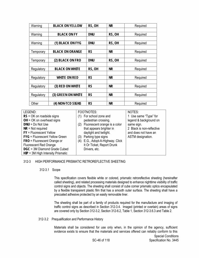
Special Conditions SC-46 of 118 Specification No. 3445
Warning BLACK ON YELLOW RS, OH NR Required Warning BLACK ON FY DNU RS, OH Required Warning (1) BLACK ON FYG DNU RS, OH Required Temporary BLACK ON ORANGE RS NR Required Temporary (2) BLACK ON FRO DNU RS, OH Required Regulatory BLACK ON WHITE RS, OH NR Required Regulatory WHITE ON RED RS NR Required Regulatory (3) RED ON WHITE RS NR Required Regulatory (3) GREEN ON WHITE RS NR Required Other (4) NON-TCD SIGNS RS NR Required
LEGEND: RS = OK on roadside signs OH = OK on overhead signs DNU = Do Not Use NR = Not required FY = Fluorescent Yellow FYG = Fluorescent Yellow Green FRO = Fluorescent Orange or Fluorescent Red Orange DGC = 3M Diamond Grade Cubed HIP = 3M High Intensity Prismatic
FOOTNOTES: (1) For school zone and
pedestrian crossing. (2) Fluorescent orange is a color
that appears brighter in daylight and twilight.
(3) Parking type signs (4) E.G., Adopt-A-Highway. Click
It Or Ticket, Report Drunk Drivers, etc.
NOTES: 1 Use same “Type” for legend & background on same sign. 2 Black is non-reflective and does not have an ASTM designation.
312-3 HIGH PERFORMANCE PRISMATIC RETROREFLECTIVE SHEETING
312-3.1 Scope This specification covers flexible white or colored, prismatic retroreflective sheeting (hereinafter
called sheeting), and related processing materials designed to enhance nighttime visibility of traffic control signs and objects. The sheeting shall consist of cube corner prismatic optics encapsulated by a flexible transparent plastic film that has a smooth outer surface. The sheeting shall have a precoated adhesive protected by an easily removable liner.
The sheeting shall be part of a family of products required for the manufacture and imaging of
traffic control signs as described in Section 312-3.4. Imaged (printed or overlain) areas of signs are covered only by Section 312-3.2, Section 312-6.2, Table 1, Section 312-3.6.3 and Table 2.
312-3.2 Prequalification and Performance History
Materials shall be considered for use only when, in the opinion of the agency, sufficient evidence exists to ensure that the materials and services offered can reliably conform to this

Special Conditions SC-47 of 118 Specification No. 3445
specification. The sheeting manufacturer shall provide evidence of performance and suitability for use in accordance with the Agency’s Qualified Products Procedures
312-3.3 Classification and Conformance
The sheeting shall meet the performance requirements contained in all of the standards and specifications listed below, as modified herein. The sheeting need not conform to any construction or composition limitations included in the reference specifications; and the retroreflectance measurements shall be limited to observation angles less than 2.0°. AASHTO M 268 Type III and Type IV AS/NZ 1906.1 Class 1 ASTM D 4956 Type III and Type IV BS 873 Class 1 CGSB 62-GP-11 Type 1 DIN 67520 Type 2 EN 12899-1 Class 2 FP-03 Type III and Type IV GB/T 18833 Class 3 JT/T 279 Class 3 NBR 14644 Type II NTC 4739 Type III and IV SABS 1519.1 Class III
The adhesive shall be a pressure-sensitive adhesive of the aggressive tack type requiring no heat,
solvent or other preparation for adhesion to smooth, clean surfaces when properly applied at temperatures above 50�F. For application to rough surfaces, a surface primer may be required.
312-3.4 Imaging Systems
312-3.4.1 Process Inks
The process colors shall be a single line of traffic colors which may be applied before
and after the sheeting is applied to a substrate; require no component premixing; and will air dry for packing in 4 hours or less and requires no clear coating.
312-3.4.2 Overlay Films
The sheeting manufacturer shall also manufacture colored imaging films and clear protective overlays, which are compatible with the sheetings, and when used in accordance with the sheeting manufacturer’s instructions shall not lessen the warranty term as described in Section 312-3.7.2.
312-3.5 Test Panels and Test Conditions
Unless otherwise specified herein, when tests are to be performed using test panels, the specimens shall be applied to smooth aluminum 0.020 in. (0.508 mm), 0.040 in. (1.016 mm) or 0.063 in. (1.600 mm) in thickness cut from Alloy 6061-T6 or 5052-H38. The aluminum shall be degreased and lightly acid etched before the specimens are applied. Unless otherwise specified, all test samples shall be conditioned for 24 hours prior to testing and all tests shall be conducted at a temperature of 73 ± 3°F (23 ± 2°C) and 50 ± 5 % relative humidity.
312-3.6 Material Requirements
312-3.6.1 Color Requirements:

Special Conditions SC-48 of 118 Specification No. 3445
Color shall be as specified and shall conform to the requirements for standard highway colors as defined all the standards and specifications listed in Section 312-3.3 above.
312-3.6.2 Coefficient of Retroreflection:
The coefficients of retroreflection shall be determined in accordance with ASTM E-810, for the minimum requirements of Table 1, as specified.
312-3.6.2A Units: Coefficients of retroreflection shall be specified in units of candelas per
lux per square meter. The observation angles shall range from 0.2° to 1.0�. The entrance angles shall range from –4° to 40°.
312-3.6.2B For screen printed transparent colored areas on white sheeting, the coefficients
of retroreflection shall not be less than 70% of the values for corresponding color in the above table. Standard traffic colors not available in integrally colored sheeting may be produced using acrylic overlay films.
312-3.6.3 Color Processing:
The retroreflective sheeting shall be designed to work in concert with recommended imaging systems. Color processing with compatible transparent and opaque process colors shall be possible in accordance with the sheeting manufacturer's recommendation at temperatures of 66 to 100�F (16 to 38�C) and relative humidity of 20 to 80%. The sheeting shall be heat resistant and permit force curing without staining of applied or unapplied sheeting at temperatures recommended by the sheeting manufacturer.
312-3.6.4 Flexibility:
The reflective sheeting shall be sufficiently flexible to show no cracking during application to substrates in accordance with the manufacturer’s instructions.
312-3.6.5 Adhesion:
The retroreflective sheeting shall comply with the liner removal and adhesion requirements contained in the standards and specifications listed in Section 312-3.3.
312-3.6.6 Impact Resistance:
The retroreflective sheeting shall comply with the impact resistance requirements contained in the standards and specifications listed in Section 312-3.3.
213-3.6.7 Resistance to Accelerated Weathering:
The retroreflective sheeting shall comply with the weathering resistance requirements contained in the standards and specifications listed in Section 312-3.3.
312-3.6.8 Resistance to Heat, Cold and Humidity:
Three samples of retroreflective sheeting, 3 x 6 inch, applied to test panels in accordance with Section 312-3.5 above, shall be exposed as follows:

Special Conditions SC-49 of 118 Specification No. 3445
312-3.6.9 Heat:
One specimen shall be placed in an oven at 160°F + 5°F (71° C + 3° C) for 24 hours, then conditioned as in Section 312-3.5 for 2 hours.
312-3.6.10 Cold:
The second specimen shall be exposed to an air temperature of -70°F + 5°F (57°C + 3°C) for 72 hours, then conditioned as in Section 312-3.5 for 2 hours.
312-3.6.11 Humidity:
The final specimen shall be subjected to 100% relative humidity at a temperature of 75° - 78°F (23°- 27°C) in accordance with US Federal Test Method Standard 141, method 6201, for 24 hours, then conditioned as in Section 312-3.5 for 24 hours.
Examination of each of the three samples following the exposures shall show no
evidence of cracking, peeling, chipping or delamination from the test panel. After heat exposure the sheeting shall retain a minimum of 85% and a maximum of 115% of the original coefficient of retroreflection when measured at room temperature.
Table 1
Minimum Coefficient of Retroreflection (Candelas per Lux per Square Meter)
White Green
-4/5 30 40 -4/5 30 40
0.2 360 175 90 0.2 50 30 8
0.5 150 70 45 0.5 21 12 3.0
1.0 20 10 9.0 1.0 2.0 2.0 0.8
Yellow Blue
-4/5 30 40 -4/5 30 40
0.2 270 135 65 0.2 30 14 5.0
0.5 110 60 32 0.5 13 6.0 2.0
1.0 14 8.5 7.0 1.0 1.0 0.8 0.5
Red Brown
-4/5 30 40 -4/5 30 40

Special Conditions SC-50 of 118 Specification No. 3445
0.2 65 35 15 0.2 18 8.5 2.0
0.5 27 14 7 0.5 7.5 3.5 1.0
1.0 3.0 2.0 1.0 1.0 1.0 0.2 0.1
Orange
-4/5 30 40
0.2 145 70 29
0.5 60 28 14
1.0 5.0 3.0 1.0
312-3.7 Performance Requirements and Obligations
312-3.7.1 Certification. The sheeting manufacturer shall submit with each lot or shipment,
certification that states that the material supplied will meet all the requirements listed herein. 312-3.7.2 Field Performance Requirements
Sheeting processed and applied to sign blank materials in accordance with sheeting manufacturer's recommendations, shall perform effectively for the number of years stated in Table 2 of this specification. The retroreflective sheeting will be considered unsatisfactory if it has deteriorated due to natural causes to the extent that: (1) the sign is ineffective for its intended purpose when viewed from a moving vehicle under normal day and night driving conditions; or (2) the coefficient of retroreflection is less than the minimum specified for that sheeting during that period listed in Table 2. All measurements shall be made after sign cleaning according to sheeting manufacturer's recommendations.
Table 2
Minimum Coefficient of Retroreflection Candelas per Lux per Sq-Meter
(.2� obs, and -4� entrance)
Minimum Minimum Coefficient Coefficient Sheeting of Retro. of Retro. Color (7 years)1 (10 years) White 288 250 Yellow 216 170 Green 40 35 Red 52 45
1 When sheeting is used in temporary work zone applications the warranty period shall be limited to 3 years
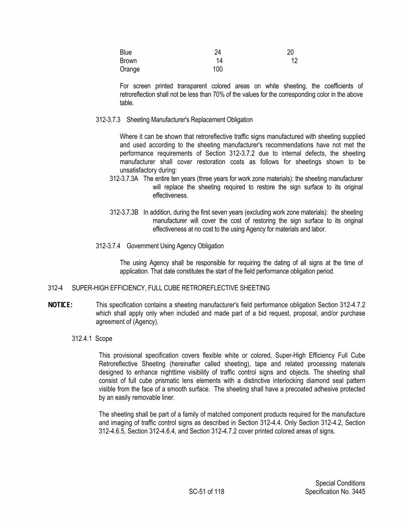
Special Conditions SC-51 of 118 Specification No. 3445
Blue 24 20 Brown 14 12 Orange 100
For screen printed transparent colored areas on white sheeting, the coefficients of retroreflection shall not be less than 70% of the values for the corresponding color in the above table.
312-3.7.3 Sheeting Manufacturer's Replacement Obligation
Where it can be shown that retroreflective traffic signs manufactured with sheeting supplied and used according to the sheeting manufacturer's recommendations have not met the performance requirements of Section 312-3.7.2 due to internal defects, the sheeting manufacturer shall cover restoration costs as follows for sheetings shown to be unsatisfactory during:
312-3.7.3A The entire ten years (three years for work zone materials): the sheeting manufacturer will replace the sheeting required to restore the sign surface to its original effectiveness.
312-3.7.3B In addition, during the first seven years (excluding work zone materials): the sheeting
manufacturer will cover the cost of restoring the sign surface to its original effectiveness at no cost to the using Agency for materials and labor.
312-3.7.4 Government Using Agency Obligation
The using Agency shall be responsible for requiring the dating of all signs at the time of application. That date constitutes the start of the field performance obligation period.
312-4 SUPER-HIGH EFFICIENCY, FULL CUBE RETROREFLECTIVE SHEETING NOTICE: This specification contains a sheeting manufacturer's field performance obligation Section 312-4.7.2
which shall apply only when included and made part of a bid request, proposal, and/or purchase agreement of (Agency).
312.4.1 Scope
This provisional specification covers flexible white or colored, Super-High Efficiency Full Cube Retroreflective Sheeting (hereinafter called sheeting), tape and related processing materials designed to enhance nighttime visibility of traffic control signs and objects. The sheeting shall consist of full cube prismatic lens elements with a distinctive interlocking diamond seal pattern visible from the face of a smooth surface. The sheeting shall have a precoated adhesive protected by an easily removable liner.
The sheeting shall be part of a family of matched component products required for the manufacture and imaging of traffic control signs as described in Section 312-4.4. Only Section 312-4.2, Section 312-4.6.5, Section 312-4.6.4, and Section 312-4.7.2 cover printed colored areas of signs.
Special Conditions SC-52 of 118 Specification No. 3445
312.4.2 Prequalification Materials (sheeting, process colors, overlay films) shall be considered for use only when, in the opinion of (Agency), sufficient evidence exists to ensure that the materials and services offered can reliably conform to this provisional specification.
312-4.3 Classification and Conformance
312-4.3.1 The sheeting shall conform to ASTM D 4956-05 as modified by this special provision.
312-4.4 Items to be Included in Bids
312-4.4.1 Process Colors
312-4.4.1A The manufacturer of the sheeting shall manufacture and offer process colors in standard traffic colors, clears and thinners recommended for the sheeting to meet the performance requirements of this specification.
312-4.4.1B The process colors shall be a single line of traffic colors which may be applied before
and after sheeting is applied to a substrate, require no component premixing, and will air dry for packing with proper ventilation in 3 hours or less and require no clear coating.
312-4.4.2 Overlay Films
The sheeting manufacturer shall also manufacture colored acrylic imaging films and clear protective overlays, which are compatible with the sheetings, and when used in accordance with the sheeting manufacturer’s instructions, shall not lessen the warranty term as described in Section 312-4.7.2.
312-4.5 Test Panels and Test Conditions
Unless otherwise specified herein, sheeting shall be applied to test panels in accordance with ASTM D 4956-05, Section 312-4.7.2 and test conditions shall conform to ASTM D 4956-05 Section 312-4.7.1.
312-4.6 Requirements
312-4.6.1 Color Requirements
312-4.6.1.1 Colors
Color shall be as specified and shall conform to the requirements of ASTM D 4956-05, Table 17. Luminance factors shall conform to Table 10 for ordinary colors and Table 14 for fluorescent colors.
312-4.6.1.2 Ordinary Colors
Conformance to standard chromaticity (x, y) and luminance factor (Y%) requirements shall be determined by instrumental method in accordance with ASTM E 1164 on sheeting applied to smooth aluminum test panels cut from Alloy 6061-T6 or 5052-H38. The values shall be determined on a HunterLab ColorFlex
Special Conditions SC-53 of 118 Specification No. 3445
45/0 spectrophotometer. Computations shall be done for CIE Illuminant D65 and the 2o standard observer.*
312-4.6.1.3 Fluorescent Colors
Conformance to standard chromaticity (x,y) and luminance factor (Y%) requirements shall be determined by instrumental method in accordance with ASTM E 991 on sheeting applied to smooth aluminum test panels cut from Alloy 6061-T6 or 5052-H38. The values shall be determined on a HunterLab ColorFlex 45/0 spectrophotometer. Computations shall be done for CIE Illuminant D65 and the 2o standard observer.*
* The instrumentally determined color values of ordinary and fluorescent colored retroreflective sheeting can vary significantly depending on the make and model of colorimetric spectrophotometer as well as the color and retroreflective optics of the sheeting (David M. Burns and Timothy J. Donahue, Measurement Issues in the Color Specification of Fluorescent-Retroreflective Materials for High Visibility Traffic Signing and Personal Safety Applications, Proceedings of SPIE: Fourth Oxford Conference on Spectroscopy, 4826, pp. 39-49, 2003). For the purposes of this document, the HunterLab ColorFlex 45/0 spectrophotometer shall be the referee instrument.
312-4.6.2 Coefficient of Retroreflection
312-4.6.2.1 Conformance to minimum requirements for Retroreflectance is determined as follows:
312-4.6.2.2 Three 8 in. x 8 in. samples spaced evenly across and down a representative
piece of sheeting shall be taken. The Coefficient of Retroreflection (Ra) shall be determined for each of the three samples per ASTM E810. The average of the three values shall comply with the stated minimum table value and no single sample shall be less than 80% of the table value.
312-4.6.2.3 The observation angles shall be 0.2°, 0.5°, 1.0°.
312-4.6.2.4 The entrance angles shall be -4° and 30°.
312-4.6.2.5 For screen printed transparent colored areas or transparent colored overlay
films on white sheeting, the coefficients of retroreflection shall not be less than 70% of the values for corresponding color in Table I.
312-4.6.3 Fractional Retroreflectance
The optical design of the sheeting shall be such that when measured at an entrance angle of –4° the fractional retroreflectance within a 2° observation angle cone, as defined in ASTM E808 as RT with αmax = 2°, is at least 55%.
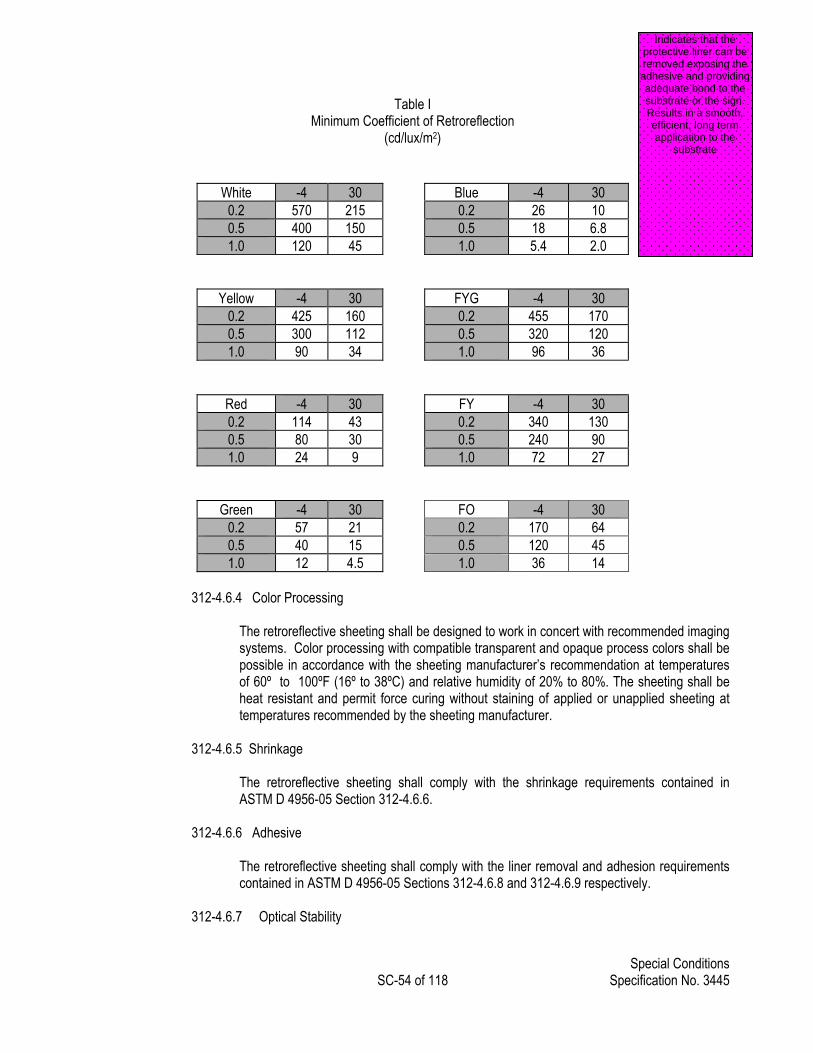
Special Conditions SC-54 of 118 Specification No. 3445
Table I Minimum Coefficient of Retroreflection
(cd/lux/m2)
White -4 30 Blue -4 30 0.2 570 215 0.2 26 10 0.5 400 150 0.5 18 6.8 1.0 120 45 1.0 5.4 2.0
Yellow -4 30 FYG -4 30 0.2 425 160 0.2 455 170 0.5 300 112 0.5 320 120 1.0 90 34 1.0 96 36
Red -4 30 FY -4 30 0.2 114 43 0.2 340 130 0.5 80 30 0.5 240 90 1.0 24 9 1.0 72 27
Green -4 30 FO -4 30 0.2 57 21 0.2 170 64 0.5 40 15 0.5 120 45 1.0 12 4.5 1.0 36 14
312-4.6.4 Color Processing
The retroreflective sheeting shall be designed to work in concert with recommended imaging systems. Color processing with compatible transparent and opaque process colors shall be possible in accordance with the sheeting manufacturer’s recommendation at temperatures of 60º to 100ºF (16º to 38ºC) and relative humidity of 20% to 80%. The sheeting shall be heat resistant and permit force curing without staining of applied or unapplied sheeting at temperatures recommended by the sheeting manufacturer.
312-4.6.5 Shrinkage
The retroreflective sheeting shall comply with the shrinkage requirements contained in ASTM D 4956-05 Section 312-4.6.6.
312-4.6.6 Adhesive The retroreflective sheeting shall comply with the liner removal and adhesion requirements contained in ASTM D 4956-05 Sections 312-4.6.8 and 312-4.6.9 respectively.
312-4.6.7 Optical Stability
Indicates that the protective liner can be removed exposing the adhesive and providing adequate bond to the substrate or the sign. Results in a smooth, efficient, long term application to the
substrate

Special Conditions SC-55 of 118 Specification No. 3445
Three samples of retroreflective sheeting applied to test panels and conditioned as in Section 312-4.5 shall each first have their photometric properties characterized by measuring the coefficients of retroreflection in accordance with ASTM E 810 at all test geometries shown in Table I. These panels shall then be exposed in an air circulating oven at 160 ± 5°F (71± 3°C) for a period of 24 hours. After exposure the panels shall be allowed to condition according to the provisions of Section 312-4.5. These panels will again be characterized for photometric properties by measuring the coefficients of retroreflection at all test geometries measured before exposure.
The coefficients of retroreflection measured after exposure shall be between 85% and 115%
of the values measured before exposure for each of the three samples.
312-4.6.8 Fungus resistance
The retroreflective sheeting shall comply with the supplementary requirements contained in section S1 of ASTM D 4956-05.
312-4.6.9 General Characteristics and Packaging
The retroreflective sheeting as supplied shall be of good appearance, free from ragged edges, cracks and extraneous materials and shall be furnished in either rolls or sheets.
When furnished in continuous rolls, the number of splices shall not be more than two per 50 yards (45.7 m) of material, with a maximum of three pieces in any 50-yard (45.7 m) length. Splices shall be butted or overlapped and shall be suitable for continuous application as furnished.
The sheeting shall be packaged in accordance with commercially accepted standards. Each
carton shall clearly stipulate the brand, quantity, size, lot or run number, color and type adhesive. Stored under normal conditions the retroreflective sheeting as furnished shall be suitable for use for a minimum period of one year.
312-4.7 Performance Requirements and Obligations
312-4.7.1 Certification
The sheeting manufacturer shall submit with each lot or shipment, a certification that states the material supplied will meet all the requirements listed herein.
312-4.7.2 Field Performance Requirements
312-4.7.2.1 For Permanent Signing – Ordinary Colors:
Sheeting manufactured of ordinary colors and processed and applied to sign blank materials in accordance with sheeting manufacturer’s recommendations, shall perform effectively for at least 12 years. The retroreflective sheeting will be considered unsatisfactory if it has deteriorated due to natural causes to the extent that: (1) the sign is ineffective for its intended purpose when viewed from a moving vehicle under normal day and night driving conditions; or (2) the coefficient of retroreflection is less than the minimum specified for that sheeting during that period listed.
Special Conditions SC-56 of 118 Specification No. 3445
80% of values listed in Table I up to 7 years and 70% of values listed in Table I up to 12 years Failure of process colors or overlay films provided and/or sold for use on recommended sheeting shall constitute a failure of the sign and shall be replaced under the manufacturer’s replacement obligations (Section 312-4.7.3). For screen printed transparent colored areas or transparent colored overlay films on white sheeting, the coefficients of retroreflection shall not be less than 70% of the values for the corresponding integral color. All measurements shall be made after sign cleaning according to the sheeting manufacturer’s recommendations.
312-4.7.2.2 For Permanent Signing – Fluorescent Colors:
Sheeting manufactured of fluorescent colors and processed and applied to sign blank materials in accordance with sheeting manufacturer’s recommendations shall perform effectively for the number of years stated in this specification. The retroreflective sheeting will be considered unsatisfactory if it has deteriorated due to natural causes to the extent that: (1) the sign is ineffective for its intended purpose when viewed from a moving vehicle under normal day and night driving conditions; or (2) the coefficient of retroreflection is less than the minimum specified for that sheeting during that period listed.
80% of values listed in Table I up to 7 years* and 70% of values listed in Table I up to 10* years
Failure of process colors or overlay films provided and/or sold for use on recommended sheeting shall constitute a failure of the entire sign and shall be replaced under the manufacturer’s replacement obligations (Section 312-4.7.3).
All measurements shall be made after sign cleaning according to sheeting the manufacturer’s recommendations.
* 5 years in states listed in Table II * 7 years in states listed in Table II
Table II Minimum Total Luminance Factor
(All measurements shall be made after cleaning according to manufacturer's recommendations)
Color
Warranty Period
Minimum Total Luminance Factor YT %
Fluorescent Yellow 10 Years*
45%
Fluorescent Yellow Green 10 Years*
60%

Special Conditions SC-57 of 118 Specification No. 3445
*Due to climatic conditions, the warranty in the following states will be a seven year warranty: Alabama, Arizona, Florida, Georgia, Hawaii, Louisiana, Mississippi, New Mexico, South Carolina, Texas
312-4.7.2.3 For Temporary Signing – Fluorescent Orange Colors
Sheeting manufactured of fluorescent orange and applied to sign blank material in accordance with the sheeting manufacturer’s recommendations, is expected to perform effectively for a minimum of three years. The retroreflective sheeting will be considered unsatisfactory if it has deteriorated due to natural causes to the extent that: (1) the sign is ineffective for its intended purpose or (2) retains less than 50% of the coefficient of retroreflection values listed in Table I at 0.2 degrees observation, -4 degrees entrance (measured in accordance with ASTM E810).
All measurements shall be made after sign cleaning according to the sheeting
manufacturer’s recommendations.
Natural causes include effects of exposure to weather. Natural causes exclude (without limitation) damage from exposure to chemicals, abrasion and other mechanical damage (such as from fasteners used to mount the sign, collisions or mishandling), vandalism, or malicious mischief.
312-4.7.3 Sheeting Manufacturer’s Replacement Obligation
312-4.7.3.1 For ordinary colors where it can be shown that retroreflective signs, supplied
and used according to the sheeting manufacturer’s recommendations, have not met the performance requirements of Section 312-4.7.2, the sheeting manufacturer shall cover restoration costs as follows for sheetings shown to be unsatisfactory during:
312-4.7.3.1A For the entire 12 years, the sheeting manufacturer will replace the
sheeting required to restore the sign surface to its original effectiveness.
312-4.7.3.1B In addition, during the first seven years the sheeting manufacturer will cover the cost of restoration of the sign surface to its original effectiveness at no cost to (Agency) for materials and labor.
312-4.7.3.2 For fluorescent colors where it can be shown that retroreflective signs,
supplied and used according to the sheeting manufacturer’s recommendations, have not met the performance requirements of Section 312-4.7.2, the sheeting manufacturer shall cover restoration costs as follows for sheetings shown to be unsatisfactory:
312-4.7.3.2A For those states with a 10 year warranty, if the failure occurs within
the first 7 years from the date of fabrication, the sheeting manufacturer shall, at its expense, restore the sign surface to its original effectiveness.
312-4.7.3.2B If the failure occurs in the 8th through the 10th year from the date
of fabrication, the sheeting manufacturer will furnish the necessary amount of sheeting to restore the sign surface to its original effectiveness.

Special Conditions SC-58 of 118 Specification No. 3445
312-4.7.3.2C Replacement sheeting shall carry the unexpired warranty of the sheeting it replaces.
312-4.7.3.2D For those states with a 7 year warranty, if the failure occurs within
the first 5 years from the date of fabrication, the manufacturer will, at its expense, restore the sign surface to its original effectiveness.
312-4.7.3.2E If the failure occurs within the 6th or 7th year from the date of
fabrication, the manufacturer will furnish the necessary amount of sheeting necessary to restore the sign surface to its original effectiveness.
312-4.7.3.2F Replacement sheeting shall carry the unexpired warranty of the
sheeting it replaces.
312-4.7.3.3 For temporary signing, fluorescent orange, where it can be shown that the retroreflective sheeting fails to conform to the performance requirements of Section 312-4.7.2, the sheeting manufacturer’s sole responsibility and purchaser’s and user’s exclusive remedy shall be:
312-4.7.3.3A Provide replacement sheeting. This sheeting shall carry the unexpired warranty of the sheeting it replaces
312-4.7.3.4 (Agency) Obligation
(Agency) shall be responsible for requiring the dating of all signs at the time of application. That date constitutes the start of the field performance obligation period.
312-4.8 Applicable Documents
The following documents, of the issues in effect on the date of invitation for bids or request for proposal, form a part of this specification to the extent specified herein.
312-4.8.1 ASTM Standards
D 4956 Standard Specification for Retroreflective Sheeting for Traffic Control. 312-4.8.2 E 810 Standard Test Method for Coefficient of Retroreflection of Retroflective Sheeting.
312-5 PREMIUM PROTECTIVE OVERLAY FILM 312-5.1 Scope
This specification covers premium transparent protective overlay film designed for application to sign faces reflectorized with retroreflective sheeting to provide a superior barrier to staining by graffiti and other markings.
Special Conditions SC-59 of 118 Specification No. 3445
312-5.2 Description
The protective overlay film shall be a clear, non-chlorinated, colorless film which may be used in lieu of clear coating. It shall be durable, solvent resistant and shall be coated with a transparent, UV stabilized pressure sensitive adhesive protected by an easily removable paper liner.
312-5.3 Compatibility
The protective overlay film shall be compatible with reflective sheeting and inks used for signing. This compatibility shall be clearly designated by the manufacturers of each component or, alternately, each component shall be produced by a single manufacturer.
312-5.4 Performance Requirements
312.5.4.1 Tensile Strength. A 1" (25mm) wide sample of protective overlay film, with the liner removed shall have a minimum tensile strength of 4500 psi when tested at 72F (23C) using a jaw speed of 5 inches per minute.
312-5.4.2 Dimensional Stability. The protective overlay film, without adhesive, shall have a
minimum melt point of 520F (270C). 312-5.4.3 Color. When protective overlay film is applied in accordance with the manufacturer's
recommendation over retroreflective sheeting, the color of the film/sheeting composite shall conform to the color requirements of the screen processed colors for the type of sheeting material used.
312-5.4.4 Transparency. The overlay film, without adhesive, shall provide a minimum of 95%
transmittance of light in the visible range (400 - 700 nanometers.) The overlay film shall remain transparent through the expected life of the sheeting to which it is applied.
312-5.4.5 Solvent Resistance. The protective overlay film, without adhesive shall show no swelling
or crazing after immersion in any of the following solvents for 7 days:
Methylene Chloride Toluene Ethyl Acetate Gasoline Mineral Spirits Naphtha
312-5.4.6 Cleanability. The overlay film manufacturer shall identify acceptable cleaning systems
sufficient to clean paint and other surface contaminants without damaging the sign face. 312-5.4.7 Field Performance. The expected performance life of a sign face constructed of overlay
film and reflective sheeting shall be equivalent to the expected performance life of the retroreflective material used.
312-5.4.8 Storage. The overlay film, when stored in accordance with the manufacturer's
recommendations shall be suitable for use up to 1 year from date of purchase.

Special Conditions SC-60 of 118 Specification No. 3445
SECTION 11 – NOT USED
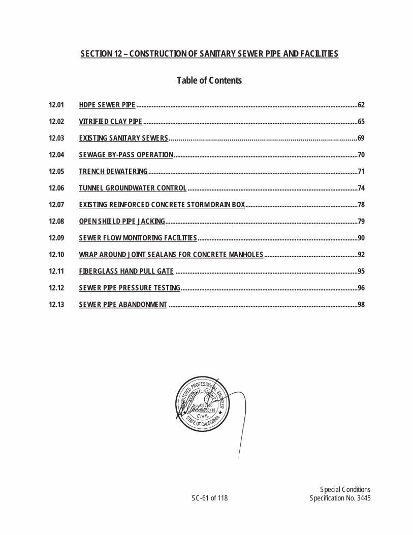
Special Conditions SC-61 of 118 Specification No. 3445
SECTION 12 – CONSTRUCTION OF SANITARY SEWER PIPE AND FACILITIES
Table of Contents
12.01 HDPE SEWER PIPE .................................................................................................................................. 62
12.02 VITRIFIED CLAY PIPE .............................................................................................................................. 65
12.03 EXISTING SANITARY SEWERS…………………………………………………………………………………69
12.04 SEWAGE BY-PASS OPERATION ............................................................................................................ 70
12.05 TRENCH DEWATERING ........................................................................................................................... 71
12.06 TUNNEL GROUNDWATER CONTROL .................................................................................................... 74
12.07 EXISTING REINFORCED CONCRETE STORM DRAIN BOX .................................................................. 78
12.08 OPEN SHIELD PIPE JACKING ................................................................................................................. 79
12.09 SEWER FLOW MONITORING FACILITIES .............................................................................................. 90
12.10 WRAP AROUND JOINT SEALANS FOR CONCRETE MANHOLES ....................................................... 92
12.11 FIBERGLASS HAND PULL GATE ........................................................................................................... 95
12.12 SEWER PIPE PRESSURE TESTING ........................................................................................................ 96
12.13 SEWER PIPE ABANDONMENT ............................................................................................................... 98

Special Conditions SC-62 of 118 Specification No. 3445
SECTION 12 – CONSTRUCTION OF SANITARY SEWER PIPE AND FACILITIES 12.01. HDPE SEWER PIPE 1. General Requirements
A. The CONTRACTOR shall provide DRISCOPLEX® high density polyethylene pressure pipe, complete and in place, all in accordance with the Contract Documents.
2. Reference Specifications, Codes, and Standards
A. Reference Specifications:
i. Section 2.30
B. Commercial Standards:
i. ANSI/AWWA C 906 High Density Polyethylene (HDPE) Pressure Pipe and Fittings
ii. ASTM D 3350 Polyethylene Plastics Pipe and Fittings Materials
C. CONTRACTOR Submittals
i. Shop Drawings: The CONTRACTOR shall submit shop drawings of pipe, fittings, and appurtenances.
ii. Certifications: The CONTRACTOR shall furnish a certified affidavit of compliance for all pipe and other products or materials furnished under this Section of the Specifications:
a. Hydrostatic proof test reports.
b. Sustained pressure test reports.
c. Burst strength test reports.
iii. All expenses incurred in making samples for certification of tests shall be borne by the CONTRACTOR.
D. Quality Assurance
i. Experience and Certification: The CONTRACTOR who performs the installation and fusion welding of the HDPE pipe shall have at least 5 years of recent experience within the last 10 years doing similar size and length work. A certificate of experience of the workers shall be submitted for review and approval.
ii. Inspection: All pipes shall be subject to inspection at the place of manufacture in accordance with the provisions of the referenced standards as supplemented by the requirements herein. The CONTRACTOR shall notify the ENGINEER in writing of the manufacturing starting date not less than 14 calendar days prior to the start of any phase of the pipe manufacture.

Special Conditions SC-63 of 118 Specification No. 3445
iii. During the manufacture of the pipe, the ENGINEER shall be given access to all areas where manufacturing is in process and shall be permitted to make all inspections necessary to confirm compliance with the Specifications.
iv. Tests: Except as modified herein, materials used in the manufacture of the pipe shall be tested in accordance with the requirements of this Section of the Specifications, as specified in the referenced standards, as applicable. And the testing of the first fusion welds should be done and witnessed by the ENGINEER. All butt fusion welds shall be logged in a data logger to maintain quality control. The joint data shall be available to the City on a daily basis.
v. If any butt fusion welded joint does not meet the parameters of the printout, shall be cut-out and rewelded.
vi. Each joint shall be number and tracked with the data logger for later identification.
vii. The CONTRACTOR shall perform said material tests in accordance with the requirements of the Contract Documents. The ENGINEER shall have the right to witness all testing conducted by the CONTRACTOR, provided that the CONTRACTOR'S schedule is not delayed for the convenience of the ENGINEER.
viii. In addition to those tests specifically required, the ENGINEER may request additional samples of any material for testing by the OWNER. The additional samples shall be furnished as part of the WORK.
3. Products
A. General
i. Materials: The high density polyethylene pipe and fittings shall be made from prime virgin resins PE4710 as defined in ASTM D 3350 with an established hydrostatic-design basis of 1600 psi for water at 73 degrees F. The resin shall be listed by the PPI (Plastic Pipe Institute) in its pipe-grade registry Technical Report (TR) 4, "Listing of Plastic Pipe Compounds.
ii. Pipe and Fittings: Pipe OD sizes 4-inch to 24-inch shall be available both in steel pipe sizes (IPS) and ductile iron pipe sizes (DIPS). Pipe OD sizes 26-inch to 54-inch OD shall be available in steel pipe sizes. All pipes shall be suitable for use as a fluid pressure conduit. The net pressure capability shall be 160 psi, DR 21.0.The pipe shall be joined by heat fusion, flanges or other proven and accepted mechanical joint system for HDPE pipe as shown on the Drawings. Both pipe and fittings shall be NSF listed by the manufacturer and bear the "NSF-pw" logo or mark.
iii. Color: The interior color of the pipe shall be grey. Black is not acceptable.
iv. Marking: Pipe and fittings shall be marked as prescribed by AWWA C906 and NSF. Pipe markings shall include nominal size, OD base (ie: 12-inch ductile iron pipe sizing, DIPS), dimension ratio, pressure class, AWWA C906, manufacturer's name, manufacturer's production code including day, month, year extruded, and manufacturer's plant and extrusion line, and NSF- pw logo.

Special Conditions SC-64 of 118 Specification No. 3445
v. Testing: Each manufacturer shall have an approved in-house QA/QC program providing compliance to the testing specifications and requirements of AWWA Standard C906 for both pipe and fittings.
4. Execution
A. General
i. All laying, jointing, and testing for defects and for leakage shall be performed in the presence of the ENGINEER, and shall be subject to approval before acceptance. All material found to be defective will be rejected and the CONTRACTOR shall promptly remove such materials from the Site.
ii. Installation shall conform to the requirements of AWWA M23, instructions furnished by the pipe manufacturer, and to the supplementary requirements or modifications herein. Wherever the provisions of this Section and the aforementioned requirements are in conflict, the more stringent provision shall apply.
B. Handling And Storage
i. Handling: Pipe, fittings, and accessories shall be carefully inspected before and after installation and those found defective shall be rejected. Pipe and fittings shall be free from fins and burrs. Before being placed in position, pipe, fittings, and accessories shall be cleaned, and shall be maintained in a clean condition. Proper facilities shall be provided for lowering sections of pipe into trenches. Under no circumstances shall pipe, fittings, or any other material be dropped or dumped into trenches.
ii. Storage: Pipe shall be stored, if possible, at the Site in unit packages provided by the manufacturer. Caution should be exercised to avoid compression damage or deformation to ends of the pipe. Pipe shall be stored in such a way as to prevent sagging or bending and protected from exposure to direct sunlight by covering with an opaque material while permitting adequate air circulation above and around the pipe. Gaskets shall be stored in a cool, dark place out of the direct rays of the sun, preferably in original cartons.
C. Trenching And Backfill
i. Trench excavation and backfill shall conform to the requirements of Section 2.10 -Earthwork, Section 2.26 Trenching, and as specified on Plan No. 3-1551, 3-1561 and 6701E.
D. Installation of HDPE Pipe in Trenches
i. Pipe shall be graded in straight lines, taking care to avoid the formation of any dips or low points. Pipe shall not be laid when the conditions of trench or weather are unsuitable. At the end of each day’s work, open ends of pipe shall be closed temporarily with wood blocks or bulkheads.
ii. Pipe shall be supported at its proper elevation and grade, care being taken to secure firm and uniform support. Wood support blocking will not be permitted. The full length of each section of pipe and fittings shall rest solidly on the pipe bed. Anchors and supports shall be

Special Conditions SC-65 of 118 Specification No. 3445
provided where necessary and where indicated on the drawings for fastening work into place. Fittings shall be independently supported.
iii. Short lengths of pipe shall be used in and out of each rigid joint or rigid structure. Piping that does not allow sufficient space for proper installation of jointing material shall be replaced by one of proper dimensions.
iv. Joints shall be installed according to manufacturer's recommendations. Trenches shall be kept free of water until joints have been properly made. The maximum combined deflection at any coupling shall be in accordance with the manufacturer's recommendations.
v. Pipe shall be cut by means of saws, power driven abrasive wheels, pipe cutters or other manufacturer recommended method which will produce a clean, square cut.
E. Installation of HDPE Pipe in Steel Casing
i. HDPE carrier pipe for Sanitary Sewer service will be installed inside the steel casings as shown on the drawings and specified herein.
ii. HDPE pipe lengths in 36 inch and 48 inch diameter DR 21 come standard in 50 foot lengths.
iii. HDPE carrier pipe for this installation shall be heat fusion welded.
iv. Contractor shall conduct tunneling operations and adjoining open cut operations to allow access to the steel casing by HDPE pipeline in the diameters indicated with fused joints. After fusion of the pipe into appropriate lengths, the pipeline shall be push/pulled into place down a sloping excavation to accomplish the installation. Alternately the contractor will be allowed to use reduced lengths of pipe required to fuse pipe in the shafts of bore shafts.
v. Casing spacer installation is required as the pipeline is pulled into the tunnel to align the
pipe to the required line and grade.
5. Measurement and Payment
A. Payment will be based on actual linear feet of installed pipeline to the inside face of manhole or structure as the linear foot price bid including all items described it the Payment Items
12.02. VITRIFIED CLAY PIPE
1. General
A. The Requirement
i. The CONTRACTOR shall provide High Strength Vitrified Clay Pipe sewers as specified and shown, complete, in accordance with the Contract Documents.
ii. Reference Specifications, Codes, And Standards
iii. Commercial Standards:
Special Conditions SC-66 of 118 Specification No. 3445
ASTM C 12 Practice for Installing Vitrified Clay Pipe Lines
ASTM C 301 Method of Testing Vitrified Clay Pipe
ASTM C 425 Specification for Compression Joints for Vitrified Clay Pipe and Fittings
ASTM C 700 Specification for Vitrified Clay Pipe, Extra Strength, Standard Strength, and Perforated
ASTM C 828 Practice for Low-Pressure Air Test of Vitrified Clay Pipe Lines
B. CONTRACTOR Submittals
i. Shop Drawings: The CONTRACTOR shall submit shop drawings of pipe and fittings in accordance with the requirements-CONTRACTOR Submittals, and the requirements of the referenced standards.
ii. Certifications: The CONTRACTOR shall furnish a certified affidavit of compliance for all pipe and other products or materials furnished under this Section, as specified in the referenced standards and the following supplemental requirements:
a. Hydrostatic test reports.
b. Three-edge bearing strength test reports.
C. Quality Assurance
i. Testing at Manufacturer's Plant: All pipes shall be subject to a hydrostatic pressure test and a 3-edge bearing test at the manufacturer's plant. The ENGINEER may select at random and test as specified one length of pipe for each 1000 feet or fraction thereof to be installed under this contract for the test as specified in ASTM C 301. The cost of pipe and the test shall be borne by the CONTRACTOR. Pipe will be acceptable under the test requirements specified herein when all test specimens conform to the test requirements. Should any of the test specimens fail to meet the test requirements, the manufacturer will be allowed to retest 2 additional specimens for each specimen that failed, and the pipe shall be acceptable only when all of the retest specimens meet the strength requirements.
ii. Inspection of Materials: All pipe and fittings shall be true, circular, and concentric with the barrel of the pipe, cut off on a plane at right angles to the longitudinal axis of the pipe. At no point shall the thickness of the shell of the extreme outer end of the spigot be less in thickness than the shell of the main body of the pipe. Socket ends shall be square with the longitudinal axis and shall be true, circular, and concentric with the barrel of the pipe.
iii. All pipe and fittings shall have smooth interiors and shall be free from injurious cracks, checks, blisters, broken extremities, or other imperfections.
iv. The following imperfections in the barrel or socket of a pipe or fitting will be considered injurious and cause for rejection:

Special Conditions SC-67 of 118 Specification No. 3445
a. A single crack in the barrel of the pipe or fitting extending through the entire thickness, regardless of the length of such crack; a single crack which extends through 1/5 of the barrel thickness and is over 3 inches long. Any surface fire crack which is more than 1/32-inch wide at its widest point.
b. Lumps, blisters, pits, or flakes on the interior surface of a pipe or fitting.
c. When spigot or socket of the pipe varies from a true circle more than 3 percent of its nominal diameter.
d. Any piece broken from the spigot end which extends through the barrel.
e. Tramp clays, grog, or other foreign matter which is fused permanently to the exterior or interior surface of the pipe or fittings.
2. Products
A. Pipe and Fittings
i. All pipe and fittings shall conform to the following requirements:
ii. Clay pipe and fittings shall be high strength, glazed, unless otherwise shown, and shall conform to the requirements of ASTM C 700.
B. Pipe Design Criteria
ii. General: Vitrified clay pipe shall be designed in accordance with the requirements of ASTM C 12 as applicable and as modified in this Section.
iii. Three-Edge Bearing Strength Determination: The required three-edge bearing strength shall be determined using the following equation:
a. Required Three-Edge = Design Load x Factor of Safety Bearing Strength Bedding Factor Required Three-Edge Three-Edge Bearing Bearing Strength = Test Strength in lbs/linear foot Design Load = Calculated Load on pipe in lbs/linear foot Factor of Safety = 1.75 minimum Bedding Factor = Varies, see Drawings for appropriate Trench
Configuration to obtain required three-edge bearing strength.
b. Provide a minimum of one Three-Edge Bearing strength test for each pipe reach between manholes.
iv. Design Load Determination: The earth loads will be computed using the following 2 equations for trench or embankment loading as applicable:

Special Conditions SC-68 of 118 Specification No. 3445
a. Trench Condition:
Wd = CdwBd2
Where: Wd = Earth load in pounds per linear foot Cd = Calculation coefficient Ku' = [0.13] w = [120] lb/ft3
Bd = Trench width at top of pipe, feet
b. Positive Projecting Embankment Condition:
Wc = CcwBc2
Where: Wc = Earth load in pounds per linear foot Cc = Calculation coefficient (based on rsdP of 0.75) Ku = [0.19] w = [120] lb/ft3
Bc = Outside diameter of pipe, feet v. The above 2 formulas are based on a depth of cover of 10 feet or greater. For depths of cover of
less than 10 feet HS-20 live load shall be included. For depths of cover of 3 feet or less, HS-20 live load and impact factors shall be as recommended by AASHTO in "Standard Specifications for Highway Bridges."
C. Joints
i. Except where open joints are shown, joints in vitrified clay pipe shall be made up using a factory-made bell and spigot compression joint for all pipe diameters, or a synthetic rubber collar with stainless steel or plastic shear ring and stainless steel take-up clamps, bolts, and nuts, for plain-end pipe up to 12-inch size, meeting the requirements of ASTM C 425.
3. Execution
A. General
i. The sewer shall be constructed to the alignment and grade shown. The grade line shown on the profile is the invert or interior bottom of the pipe. The excavation shall be made a sufficient distance below the grade line to allow for the placing of the sewer invert and the supporting foundation if such foundation is shown. Should the trench be excavated to a depth greater than required, the CONTRACTOR shall refill such excess excavation according to the requirements of Section 306 – Underground Conduit Construction of the SSPWC.
B. Installation of VCP
ii. Installation of pipe shall be in accordance with ASTM C 12. Pipe laying shall proceed upgrade with spigot ends pointing in direction of flow. After a section of pipe has been lowered into the prepared trench and immediately before joining the pipe, the ends of the pipe to be joined shall be cleaned, and the rubber gasket lubricated, all in accordance with the pipe manufacturer's written instructions. Assembly of the pipe length shall be in

Special Conditions SC-69 of 118 Specification No. 3445
accordance with the recommendations of the manufacturer of the type of joint used. All special tools and appliances required for joining the pipe shall be provided by the CONTRACTOR. When cutting or machining of the pipe is necessary, only tools and methods recommended in writing by the pipe manufacturer and approved by the ENGINEER shall be employed.
iii. The CONTRACTOR shall take all necessary precautions to prevent excavated or other foreign material from getting into the pipe during the laying operations. At all times, when laying operations are not in progress and at the close of the day's work, the ends of the pipe in the trench shall be closed to prevent entry to animals and foreign materials.
vi. All necessary precautions shall be taken to prevent uplift or floating of the pipe prior to the completion of the backfilling operation. The CONTRACTOR shall assume full responsibility for any damage due to this cause and shall, at its own expense, restore and replace the pipe to its specified condition and grade if it is displaced due to floating.
3. Measurement and Payment
A. Payment will be based on actual linear feet of installed pipe in the linear foot price bid including all items described it the Payment Items.
12.03. EXISTING SANITARY SEWERS
1. General
i. The CONTRACTOR shall join existing sanitary sewers in a way that no damage to the existing sewer occurs. Any pipe or structure damaged shall be replaced or repaired to the satisfaction of the ENGINEER at the CONTRACTOR’s sole expense.
ii. Before beginning the construction or reconstruction of any line which is to join an existing sanitary
sewer (both inlet and outlet), the CONTRACTOR shall excavate such join points to uncover a portion of the existing conduits and confirm the location and elevation at the junction as shown in the drawings.
iii. The CONTRACTOR shall provide CAL-OSHA approved ventilation and lighting necessary to
enable workmen to work safely in cutting and removing portions of the existing sewer pipe. All cuts shall be done with an approved power saw or powered carborundum disc. No mechanical pipe “cutter” will be allowed to be used. All cuts shall be ground smooth and true.
iv. Debris from the pipe removal operation and all other construction activities shall be prevented
from falling into the sewer system, and shall be removed from the job site. Should any debris enter the sewer system, the CONTRACTOR shall immediately contact City of Glendale Wastewater Section at (818) 548-3950, and shall remove any debris as directed.
v. Scaffolding, tools and materials of any description used when working in the existing sewer shall
not be left unattended during periods when there is flow therein.
vi. In the event of damage to the existing sewer facilities, or interruption of existing sewer flow, the CONTRACTOR shall promptly dispose of any free sewage by pumping or by other means.
Special Conditions SC-70 of 118 Specification No. 3445
vii. Sewage shall not be permitted to flow in the trenches or to be covered by backfill. Continuous sanitary sewer service in closed conduits shall be maintained at all times.
viii. All costs involved in meeting the above requirements shall be included in the unit prices bid for the
various related items of work and no additional compensation will be made therefore.
12.04. SEWAGE BY-PASS OPERATION
1. General
i. Prior to commencement of work, the CONTRACTOR shall submit to the ENGINEER for approval a proposed method of temporary by-pass connections to insure normal flow of sewage during construction, especially at nights and weekends.
ii. The CONTRACTOR shall provide for By-Pass Pumping as needed to safely, completely by-pass
around the work area from existing manholes or an approved temporary sewer connection, including sequencing the by-pass pumping with the work schedule such that the completed pipeline work can be put into service as to carry the by-pass pumping flows as the work advances up stream.
iii. All by-pass pipe joints shall be restrained.
iv. The existing sewage flow rates are shown on the Exhibit A in Appendix G. The CONTRACTOR
shall provide all pumps, equipment, piping portable power supply, lighting and a complete redundant back-up system ready and on stand- by for immediate use.
v. The CONTRACTOR shall designate a project foreman, approved by the City as the person in
charge of all by-pass pumping. Said foreman shall be available on a 24/7 basis during the by-pass operations.
2. Sewer By-Pass
i. The CONTRACTOR shall provide a Sewer By-Pass for all sewer tie-ins and where needed for the construction progress. The plan shall be submitted at least 4 weeks prior to start of by-pass start date. Included in the By-Pass Plan will be the method of flow monitoring. The by-pass operation shall include the prime pumps and 100% back-up stand-by pump system and tested, ready for use prior to start-up.
ii. Sewer By-Pass Plan shall show all existing sewer laterals, including locations of by-pass piping,
pumps, and flow rates, traffic control.
iii. Sewer By-Pass Plan shall locate all existing and proposed sewer manholes to be by-passed.
iv. Sewer By-Pass Plan shall provide a sequence of construction such that the sewer by-pass flow can be safely handled during the work. The sequence of construction shall show a numbered sequence order from first step to the final step in a written format with construction notes and sketches as appropriate for review and approval prior to beginning any sewer by-pass work.
v. All sewage by-passed will be metered either by existing metering stations, the new metering
station or a temporary one provided by the CONTRACTOR.

Special Conditions SC-71 of 118 Specification No. 3445
vi. The CONTRACTOR shall perform weekly maintenance on all by-pass equipment or sooner as
needed to keep the equipment, pumps, power generator, lights hoses, and other appearances in a good working condition.
vii. Approval of sewer-by-pass operation does not absolve the CONTRACTOR from any liability that
may arise due to a malfunction of the system, improper installation or any cause that renders the by-pass system inoperable.
3. Communication and Sewage Spill Prevention and Response Plan
i. The CONTRACTOR shall provide a Communication Plan and Sewage Spill Prevention and Response Plan (Plan) for all sewer tie-ins and where needed for the construction progress. The plan shall be submitted at least 4 weeks prior to start of by-pass start date. The communication part of the Plan shall identify the contact person and their back-up person. A communication protocol will be provided in the Plan to identify the persons for the CONTRACTOR and City to be notified for each operation and in the event of failure such as spills and high flows, the responses on an increasing for each type of risk basis.
ii. The CONTRACTOR shall provide a Spill Prevention and Response Plan per General Condition Article 2.16 E.
4. Measurement and Payment
i. All costs for sewage by-pass shall be included in the unit price bid for the various related items of work as described in Pay Items and no additional compensation will be made therefore.
12.05. TRENCH DEWATERING
1. General
A. The Requirement
i. The CONTRACTOR shall dewater trench and structure excavations, in accordance with the Contract Documents. The CONTRACTOR shall secure all necessary permits to complete the requirements of this Section of the Specifications.
ii. Existing Geotechnical Report: The Chevy Chase Sewer Diversion Project, Glendale, California, by Fugro Consultants, Inc., dated June 2013, Fugro Job No. 61110033 is the Geotechnical Report of Record for this project and is made a part of these Construction Documents. A copy of this report is provided in the Appendix E.
iii. CONTRACTOR Submittals
B. Prior to commencement of excavation, the CONTRACTOR shall submit a detailed Trench Dewatering Plan and operation schedule for dewatering of excavations. The CONTRACTOR may be required to demonstrate the proposed dewatering system and verify that adequate equipment, personnel, and materials are provided to dewater the excavations at all locations and times. The CONTRACTOR's Trench Dewatering Plan is subject to review by the ENGINEER.

Special Conditions SC-72 of 118 Specification No. 3445
C. Quality Control
i. It shall be the sole responsibility of the CONTRACTOR to control the rate and effect of the dewatering in such a manner as to avoid all objectionable settlement and subsidence.
ii. All dewatering operations shall be adequate to assure the integrity of the finished project and shall be the responsibility of the CONTRACTOR.
iii. Where critical structures or facilities exist immediately adjacent to areas of proposed dewatering, reference points shall be established and observed at frequent intervals to detect any settlement which may develop. The responsibility for conducting the dewatering operation in a manner which will protect adjacent structures and facilities rests solely with the CONTRACTOR. The cost of repairing any damage to adjacent structures and restoration of facilities shall be the responsibility of the CONTRACTOR.
2. Products
A. Equipment
i. Dewatering, where required, may include the use of well points, sump pumps, temporary pipelines for water disposal, rock or gravel placement, and other means. Standby pumping equipment shall be maintained on the jobsite.
3. Execution
A. General Requirements
i. The CONTRACTOR shall provide all equipment necessary for dewatering. It shall have on hand, at all times, sufficient pumping equipment and machinery in good working condition and shall have available, at all times, competent workmen for the operation of the pumping equipment. Adequate standby equipment shall be kept available at all times to insure efficient dewatering and maintenance of dewatering operation during power failure.
ii. Dewatering for structures and pipelines shall commence when groundwater is first encountered, and shall be continuous until such times as water can be allowed to rise in accordance with the provisions of this Section or other requirements.
iii. At all times, site grading shall promote drainage. Surface runoff shall be diverted from excavations. Water entering the excavation from surface runoff shall be collected in shallow ditches around the perimeter of the excavation, drained to sumps, and be pumped or drained by gravity from the excavation to maintain a bottom free from standing water.
iv. Dewatering shall at all times be conducted in such a manner as to preserve the undisturbed bearing capacity of the subgrade soils at proposed bottom of excavation.
v. If foundation soils are disturbed or loosened by the upward seepage of water or an uncontrolled flow of water, the affected areas shall be excavated and replaced with suitable drain rock to stabilize the foundation.

Special Conditions SC-73 of 118 Specification No. 3445
vi. The CONTRACTOR shall maintain the water level below the bottom of excavation in all work areas where groundwater occurs during excavation construction, backfilling, and up to acceptance.
vii. Flotation shall be prevented by the CONTRACTOR by maintaining a positive and continuous removal of water. The CONTRACTOR shall be fully responsible and liable for all damages which may result from failure to adequately keep excavations dewatered.
viii. If well points or wells are used, they shall be adequately spaced to provide the necessary dewatering and shall be sand packed and/or other means shall be used to prevent pumping of fine sands or silts from the surrounding subsurface soils. A continual check by the CONTRACTOR shall be maintained to ensure that the subsurface soil is not being removed by the dewatering operation.
ix. The CONTRACTOR shall dispose of water from the WORK in a suitable manner without damage to adjacent property. CONTRACTOR shall be responsible for obtaining any permits that may be necessary to dispose of water. No water shall be drained into work built or under construction without prior consent of the ENGINEER. Water shall be filtered using an approved method to remove sand and fine-sized soil particles before disposal into any drainage system.
x. The release of groundwater to its static level shall be performed in such a manner as to maintain the undisturbed state of the natural foundation soils, prevent disturbance of compacted backfill and prevent flotation or movement of structures, pipelines, and sewers.
4. Disposal of Ground Water
i. Disposal for ground water shall be to an approved storm drain or sewer. The existing storm drains system in Colorado Blvd within the City of Los Angeles is located at Edenhurst Avenue, west of Manhole No. 1 shown on Plan No. 3-1561. A disposal of the ground water into the storm drains system owned by the City of Los Angeles will require a permit from the City of Los Angeles Department of Water and Power (Requirements in Appendix F).
ii. The existing storm drains in the City of Glendale are owned by the Los Angeles County Department of Public Works (LACDPW). A discharge of the ground water into the storm drains system owned by the LACDPW will require a NPDES permit.
5. Measurement and Payment
A. Dewatering of trenches shall be considered as incidental to the construction of the WORK and all costs thereof shall be included in the various contract prices for the open trenched pipeline and proposed manholes 12 to 21 and no additional compensation will be made therefore.
Special Conditions SC-74 of 118 Specification No. 3445
12.06. TUNNEL GROUNDWATER CONTROL 1. General
A. Description
i. Scope of Work: This Section includes specifications for designing, furnishing, installing, maintaining, operating and removing systems required to control groundwater levels and hydrostatic pressures during tunnel and portal construction; disposing of pumped water; constructing, maintaining, observing, and removing of observation wells; and instrumentation for control of the system.
ii. Existing Geotechnical Report: The Chevy Chase Sewer Diversion Project, Glendale, California, by Fugro Consultants, Inc., dated June 2013, Fugro Job No. 61110033 is the Geotechnical Report of Record for this project and is made a part of these Construction Documents.
iii. Dewatering: Dewatering includes lowering the groundwater table and intersecting seepage which would otherwise emerge from the tunnel excavation; preventing loss of material from the tunnel excavation; improving the excavating and hauling characteristics of tunnel materials; and preventing rupture or heaving of the bottom of the tunnel excavation.
iv. Instrumentation: Instrumentation for control of the dewatering system includes furnishing, installing, and operating observation wells as well as reading and logging of water levels in the wells.
2. Design Criteria
i. Dewatering System: The CONTRACTOR shall design a dewatering system which will:
1. Lower the groundwater level in the ground above and up to 10 feet below the tunnel opening, and 2 feet below the bottom of the excavated tunnel invert.
2. Develop a substantially dry and stable subgrade for the performance of subsequent operations;
3. Result in no damage to adjacent properties, buildings, structures, utilities, and other work; and
4. Not remove soil particles during pumping operations.
ii. Methods: Methods may include sump pumping, single or multiple stage well point systems, eductor and ejector type systems, deep wells, and combinations thereof. It is the CONTRACTOR's responsibility to review and investigate the soils and groundwater conditions at the site and to determine the type or combination of methods necessary to provide the dewatering required to perform the work.
iii. Location: The dewatering facilities shall be located only where they will not interfere with utilities and other construction work.
Special Conditions SC-75 of 118 Specification No. 3445
iv. Modifications: Dewatering procedures which cause, or in the opinion of the ENGINEER threaten to cause, damage to new or existing facilities shall be modified so as to prevent further damage. The CONTRACTOR is responsible for determining and implementing any modifications, which shall be made at no additional expense to the OWNER.
3. Submittals ii. Shop Drawings: Prior to installation of the dewatering system, working drawings and design
data shall be submitted for review by the ENGINEER, showing the following:
1. The proposed type of dewatering system, including relief of hydrostatic head and procedure for maintaining the tunnel and portal excavations in a dewatered and hydrostatically relieved condition.
2. Arrangement, location, and depths of the components of the system.
3. A complete description of equipment to be used, with installation, operation, and maintenance procedures.
4. Standby equipment and power supply.
5. Location, size, and construction details of berms, dikes, observation wells, sumps, and discharge lines, including discharge points and plans for removing system and restoration of the area disturbed by dewatering operations.
6. Types and sizes of filters.
7. Cement-bentonite grout mix and placing procedures.
8. Design calculations demonstrating adequacy of the selected system and equipment.
iii. Records: The CONTRACTOR shall furnish the ENGINEER with the following records:
1. The average flow rate and time of operation of each pump used in the dewatering system shall be observed and recorded. Where necessary, appropriate devices, such as flow meters for observing the flow rates, shall be provided. The data, on a form approved by the ENGINEER, shall be submitted during the period that the dewatering system is in operation.
2. The elevation of the groundwater in observation wells shall be observed and recorded during the period that the dewatering system is in operation. The depth to the bottom of each observation well shall be sounded on a weekly basis to assure that fine soil particles are not penetrating the screen to build up in the standpipe. Observation well records shall be submitted to ENGINEER within 24 hours of reading.
3. During the initial period of the dewatering, required observations shall be made on a daily basis. After the initial period, when dewatering operations have stabilized, observations can be made at longer intervals as approved by the ENGINEER.
4. Job Conditions

Special Conditions SC-76 of 118 Specification No. 3445
iv. Surface Drainage: All precipitation, surface water, and groundwater shall be intercepted and diverted away from the excavations, observation wells and piezometer installations, through the use of dikes, curb walls, ditches, pipes, sumps, or other means.
v. Drainage of Excavated Area: Ditches of adequate size shall be provided and maintained to collect surface and seepage water which may enter the excavations. The water shall be diverted into sumps and drains, or pumped into drainage channels or storm drains, subject to the approval of the appropriate authority. The CONTRACTOR shall be responsible for obtaining any permits required for discharge of water from dewatering operations. When water is to be diverted into a storm drain, settling basins or other approved facilities shall be provided as required to reduce the amount of fine particles which may be carried into the drain. If a storm drain becomes blocked or its capacity restricted due to dewatering operations, arrangements shall be made with the appropriate agency to clean the drain at no additional expense to the OWNER.
5. Execution
A. Dewatering
i. Dewatering shall be accomplished in accordance with reviewed shop drawings. The ENGINEER shall be kept advised of any changes made to accommodate field conditions and, on completion of the dewatering system installation, shop drawings shall be revised and submitted.
ii. Dewatering operations shall be organized to lower the groundwater level in excavations as required for prosecution of the work, and to provide a stable, dry subgrade for the prosecution of subsequent operations.
iii. The water level shall be maintained at such lower elevations until no danger to the tunnel and related facilities can occur because of buildup of excessive hydrostatic pressure, and in any event, the water level shall be maintained a minimum of 2 feet below the excavated tunnel invert and portal excavation until all tunnel or portal work has been satisfactorily completed, unless otherwise permitted by the ENGINEER.
iv. Dewatering operations shall be prosecuted 24 hours a day, 7 days a week. Qualified personnel shall be on-site at all times to monitor system operations and to perform maintenance as necessary and to keep the dewatering system in operation. The responsible person in charge of the dewatering program shall be available for communication with the site at all times, and shall be able to be on the site within one hour of being alerted, should the need arise.
B. Dewatering Systems/Wells
i. Dewatering wells, should they be needed for the open shield jacked pipeline, will only need to be installed along the pipeline alignment to lower the groundwater 2 feet below the pipe depth. Dewatering systems described in this section shall not be used to dewater the shafts. The shafts shall be constructed with the walls water tight and dewatered in accordance with the Geotechnical Report requirements. The Dewatering Plan will determine the location, size and number of wells necessary to lower the groundwater, as well as construction details for the wells.

Special Conditions SC-77 of 118 Specification No. 3445
ii. Provide dewatering procedures and groundwater control details during trenchless operations. Include a description of the equipment to be used to treat the water, the disposal method, and where the water will be discharged.
iii. All piping, valves, treatment, power supply disposal and maintenance of the dewatering system is the responsibility of the CONTRACTOR.
iv. Damaged or destroyed watering wells shall be replaced within 48 hours, unless otherwise approved by the ENGINEER, at no additional expense to the OWNER.
v. Removal of Dewatering Wells:
1. Dewatering wells shall be removed only with the permission of the ENGINEER.
2. Dewatering wells outside paved areas shall be completely removed and backfilled with non-shrink cement-bentonite grout. The excavation shall be backfilled and the surface restored to a condition approved by the ENGINEER.
3. Dewatering wells in paved areas shall be completely removed by removing the well boxes and hole covers to the pavement subgrade. The observation well shall be filled with cement-bentonite grout and the pavement patched in accordance with the requirements of the appropriate agency.
C. Observation Wells
i. Observation wells shall be used as the primary basis for determining compliance with the dewatering requirements of this Section.
ii. The observation wells shall be installed along the alignment. The locations shall be reviewed and approved by the ENGINEER prior to the start of construction. The depths shall be pipe depth plus 10 feet. Existing wells may be used if available and appropriate. The locations of the existing 3 monitoring wells with Piezometer are shown on the Project Plans and in Fugro’s Geotechnical Report.
iii. Using approved drilling methods, 6-inch minimum diameter holes shall be drilled for observation wells, of the size and depth indicated, and cased with temporary casing. Bentonite drilling mud shall not be used in drilling holes for the observation wells. A log shall be made of the soils encountered during drilling and delivered to the ENGINEER.
iv. All cased holes shall be flushed with clean water through an approved bit, until the discharge water is free of soil particles
v. Observation Well Construction: Two-inch minimum inside diameter observation wells shall be constructed using slotted PVC well screen, filter sand, solid PVC casing, couplings, a pipe cap, and a locking hole cover. Two feet of filter sand shall be placed in the bottom of the drilled hole. A PVC casing with appropriate screen length shall be placed in the hole, and the annulus of the hole backfilled with filter sand. Temporary drill casing shall be carefully withdrawn as filter sand is added to 2 feet above the top of the well screen. A seal of no less than 2 feet of hydrated bentonite chips shall be installed above the filter sand. The remaining annular space shall be filled with cement-bentonite grout. If the well is located in a paved area, a locking well cover and a suitable precast concrete traffic boxes shall be installed.

Special Conditions SC-78 of 118 Specification No. 3445
vi. Maintenance of the observation wells is the responsibility of the CONTRACTOR.
vii. Damaged or destroyed observation wells shall be replaced within 48 hours, unless otherwise approved by the ENGINEER, at no additional expense to the OWNER.
D. Removal of Observation Wells
i. Observation wells outside paved areas shall be removed by removing PVC pipe completely. Using approved tremie methods, the observation wells shall be completely filled with non-shrink cement-bentonite grout. The excavation shall be backfilled and the surface restored to a condition approved by the ENGINEER.
ii. Observation wells in paved areas shall be removed by removing well boxes and hole covers to the pavement subgrade. The observation well shall be filled with cement-bentonite grout and the pavement patched in accordance with the requirements of the appropriate agency.
6. Disposal of Ground Water
vi. Disposal for ground water shall be to an approved storm drain or sewer. The existing storm drains system in Colorado Blvd within the City of Los Angeles is located at Edenhurst Avenue, west of Manhole No. 1 shown on Plan No. 3-1561. A disposal of the ground water into the storm drains system owned by the City of Los Angeles will require a permit from the City of Los Angeles Department of Water and Power (Requirements in Appendix F).
vii. The existing storm drains in the City of Glendale are owned by the Los Angeles County Department of Public Works (LACDPW). A discharge of the ground water into the storm drains system owned by the LACDPW will require a NPDES permit.
7. Measurement and Payment
A. All costs for tunnel dewatering shall be included in the unit bid price for the installed dewatering system “Dewatering, Dewatering Wells and Observation Wells” and no additional compensation will be made therefore.
12.07. EXISTING REINFORCED CONCRETE STORM DRAIN BOX 1. General Requirements:
A. Tunneling requirements are as follows:
i. Open Shield Pipe Jacking shall be from Station 0+92 to 28+67
ii. Protect existing reinforced concrete storm drain box from Station 28+10 to 28+30. 2. Existing Reinforced Concrete Storm Drain Box
A. The existing reinforced concrete storm drain box is 10 foot wide by 12 foot high inside. There is a concern about the presence of existing old wood and steel shoring forms and beams, brick, broken

Special Conditions SC-79 of 118 Specification No. 3445
pavement and rocks the may interfere with the open shield pipe jacking as it proceeds under the existing storm drain box. See Potholing Information on Sheet 13 of Plan No. 3-1551.
B. The CONTRACTOR shall excavate along the side of the existing storm drain box at the proposed 48” steel casing for 36” sewer alignment to expose and remove any obstructions such as rocks, old wood and steel shoring form and beam in the proposed tunnel area which may interfere with the proposed open shield pipe jacking operations.
C. Provide a temporary support system as necessary as designed by the CONTRACTOR to protect the
existing storm drain box during the removal operations. Temporary supports shall be designed, signed and stamped by a California Registered Professional ENGINEER and submitted to the ENGINEER for review and record purposes.
D. Once the 48-inch steel casing has been installed, completely back fill the excavated void around and
under the existing box culvert with 1 sack cement slurry mixture to the paving subgrade.
3. Measurement and Payment
A. All costs for temporary existing culvert protection shall be included in the contract Lump Sum price as described in Pay Item, Expose Sides of RC Box Storm Drain at Sewer Crossing in San Fernando Road and Los Angeles Street and Remove Debris.
12.08. OPEN SHIELD PIPE JACKING 1. General Requirements
A. CONTRACTOR is solely responsibility for the means and methods utilized to install the casing to the line and grade shown on the Drawings and to prevent settlement, all within the tolerances specified herein and subject to review by the ENGINEER and OWNER.
B. A “Reach” is defined as the distance between each manhole centerline. C. Casing lengths shown on the Project Plans are approximate. The CONTRACTOR shall be responsible
for determining the actual casing length such that the casing ends are extended into the boring and receiving shafts by a minimum of 12 inches.
D. Once the casing is in place install the 36” or 48” AWWA C906-07 HDPE pipe in the casing using wood,
or CONTRACTOR designed PSI casing spacers manufactured by GPT Industries or equal. E. Case spacers/skids shall be installed as specified in Section 12.09. F. The CONTRACTOR’s surveyor responsible for line and grade control shall be a Licensed Surveyor
registered in the State of California who has prior experience with similar projects.
G. Allowable Installation Tolerance: The maximum deviation at any point along the casing shall not exceed one (1) inch from the horizontal line and/or vertical grade shown on the Drawings per reach.

Special Conditions SC-80 of 118 Specification No. 3445
H. The CONTRACTOR shall immediately notify the OWNER, in writing, if any problems that would cause a schedule delay or a change to the submitted process/procedure are encountered with equipment or materials.
I. The OWNER shall have full access to the launch and receiving shafts prior to, during, and following all
open shield pipe jacking operations. This shall include, but is not limited to, visual inspection of casings and verification of line and grade. The CONTRACTOR shall provide safe access in accordance with all safety regulations.
J. No work, including the setup of traffic controls for the launch or receiving shafts, shall be performed
until the submittals required for this Section and all other sections related to the installation of casing and pipe through the casing have been accepted by the ENGINEER.
K. The CONTRACTOR shall obtain the required tunneling permit from the State of California, Department
of Industrial Relations, Division of Occupational Safety and Health, Mining and Tunneling Unit. The OSHA Underground Soil Classification is enclosed in Appendix F of Specifications.
6.2 Submittals (Addendum No. 2)
All submittals requiring structural design shall be signed by a professional civil or structural ENGINEER registered in the State of California. The submittals shall include the following:
i. Work Plan: The CONTRACTOR shall submit a Work Plan, as required in Section 6.01 of
these Special Conditions, which includes the details of the casing installation as well as the sequence of operations that will be utilized during all phases of construction, and include the following:
a. A detailed description of the equipment and procedures to be employed during
open shield pipe jacking operations. Provide manufacturer’s literature describing in detail the equipment and the proposed tunneling system including machine type, excavation method, dimensions, weight, power, thrust, torque, cutterhead configuration, the maximum excavated diameter produced, and the articulation and steering capabilities.
b. Details of the grade and alignment control system, spoils removal system including material transport equipment, method of face stabilization, and method of groundwater control
c. Provide bore shaft and receiving shaft shoring, including combination
bore/receiving shaft design and calculations prepared by a registered Civil Engineer, signed and stamped for review. Temporary boring and receiving shafts shoring shall be water tight such that groundwater does not seep into the shafts. The ENGINEER shall not specifically approve the design, but check for completeness and conformance to the design.
d. Description and details of any temporary underground facilities proposed for
operation such as lights, sump pits, mud slabs.
e. Shop drawings showing general tunneling and open shield pipe jacking operation set-up, including locations of all equipment, shaft details, staging and storage areas and emergency access around the tunnel operation.

Special Conditions SC-81 of 118 Specification No. 3445
f. Design of jacking system including maximum jacking capacity, details for
monitoring jacking forces at all jacking locations and means or methods of ensuring allowable loads are not exceeded. Include calculations showing the estimated jacking force required to complete each drive.
g. Thrust block and jacking frame design and details, including reaction transfer calculations.
h. Details of the pipe lubrication system and description of pipe lubricants to be used during pipe jacking, including manufacture’s literature and Material Safety Data Sheets.
i. Spoils removal plan which includes the location and sequence of disposal. Provide the name and address of the OWNER of the location where the spoils will be placed.
j. Provide material specifications and shop drawings of casing showing the pipe wall thickness, steel grade, and the maximum allowable axial force. A pipe certification of compliance shall be submitted. Please note that the casing placed under the railroad tracks must meet the requirements of AREA 5.4.3 for non-cathodically protected pipe.
k. Intermediate jacking station design, if used, specifications and locations, including maximum stroke, jacking force monitoring and recording details, and joint gaskets. Include details describing equipment or procedures for synchronizing open shield pipe jacking with intermediate jacking stations.
l. A safety plan for the open shield pipe jacking operations. Safety plan shall meet all local, state and national guidelines and more specifically meet the requirements of Cal/OSHA Mining and Tunneling Division. Appropriate certifications required under Cal/OSHA regulations for contractors and their workers shall be provided.
m. Provide submittal for sealing the casing portals at each shaft site with watertight seals. End Seals to be Model C, by GPT Industries, or as approved equal.
n. Provide submittal for temporary shoring for the boring and receiving shafts, which shall be water tight such that groundwater does not seep into the shafts.
o. Provide submittal for a water tight mud slab for the working area at the floor for each of the shafts. Mud Slab shall be of concrete construction; indicate thickness, reinforcing, dowels to walls (if any) and method to develop water- tight seal. Provide method of installation.
ii. Detailed and Legible Schedule of Work, which shall include, but not be limited to:
a. Traffic Control
b. Mobilization c. Site preparation

Special Conditions SC-82 of 118 Specification No. 3445
d. Open Shield Pipe Jacking e. Grouting
iii. Obstruction Removal and Contingency Plan (Plan): The CONTRACTOR shall submit a
proposed Plan and as required in Section 6.01 of these Special Conditions, which includes a plan to solve, remove and/or remedy the potential problems that may arise during open shield pipe jacking operations. The plan shall include the following scenarios:
a. Obstruction encountered during open shield pipe jacking and is removable through
the casing.
b. Utility strike. c. Deviation from planned casing alignment that exceeds specified allowable limits. d. Settlement in excess of provided tolerances. e. Settlement stabilization. f. Jacking forces in excess of estimated maximums.
iv. Daily Submittals: The following information shall be recorded during open shield pipe jacking
operations and submitted to the OWNER on a daily basis. Information shall be submitted within 2 hours of completion of the daily events or shift change, whichever is more frequent.
A. Field drawings for recording installed-built conditions. The drawings shall be red marked
with all field information and shall be properly dated. This set of drawings shall be kept up to date. No progress payments will be made until this daily update is completed and up to date.
B. Log of the open shield pipe jacking operations. At a minimum the log shall consist of the
following: a. Time and stationing of each push of jacked pipe. b. Station start and station stop each day. c. Description and volume of soils excavated per jacked pipe section. d. Incidence of ground loss, water flow and other unusual events. e. Geotechnical monitoring observations and measurements. f. Location of inserted intermediate jacking stations, if used. g. Records of tunneling machine torque and thrust data, including any conversion
factors, measured 3 times per jacked pipe section. h. Records of air and methane gas monitoring.

Special Conditions SC-83 of 118 Specification No. 3445
i. Detailed time record of excavation and pipe change-out times, including delays for each shift. Include duration and suspected causes of all delays.
j. Survey data and alignment plots of deflections from line and grade, measured a
minimum of three times per jacked pipe section. k. Quantity of injected lubricant at each injection location. l. Description of any worker safety concern or accident. m. Any other relevant observations or measurements.
A. All cost for the Work Plan, Submittals, Obstruction Removal and Contingency Plan shall be included in
the unit bid price for the various payment items and no additional compensation will be made.
2.3 Materials (Addendum No. 2)
A. Steel Casing shall:
i. Be new, smooth wall carbon steel pipe which conforms to ASTM Specification A36.
ii. Have the capacity to withstand the maximum jacking load anticipated with a safety factor of 2 or more. The casing shall also be designed to withstand reasonably anticipated long-term soil and groundwater loads with a safety factor of 1.5.
iii. Have minimum yield strength of 36,000 psi.
iv. Minimum casing diameter shall be as shown on the Drawings. Casing wall thickness shall be determined by the CONTRACTOR but shall not be less than the thickness shown on the Project Plans. Casing lengths shall be determined by the CONTRACTOR.
v. Have a difference in roundness between the major and the minor outside diameters not exceeding 1% of the specified nominal outside diameter, or ¼ inch, whichever is less.
vi. Have an outside circumference which is within 1% of the nominal circumference, or ½ inch, whichever is less.
vii. Have a minimum allowable straightness deviation in any 10-foot length of 1/8 inch.
viii. Be furnished with 1½ inch minimum diameter grout holes which conform to ASTM Specification A53, Schedule 40, with threaded plugs. a. Space holes regularly on 20-foot centers. Longitudinal spacing between grout
holes may be decreased to provide more extensive grouting, but shall not exceed 20 feet.
b. Grout holes shall be fitted with countersunk, full face, rubber gaskets to prevent infiltration of displaced earth during the jacking process.
ix. Steel casing joints shall be (1) a pressure fit type (Permalok or equal), or (2) welded. Steel
casing for welding shall be square cut with beveled ends, using a full-penetration butt weld.

Special Conditions SC-84 of 118 Specification No. 3445
B. Grout used for filling the annular space between the steel casing pipe and HPDP sewer pipe shall:
i. Be Type V Portland Cement conforming to Greenbook SSPWC Section 500-3. The grout
mix design have a compressive strength f’c = 450 psi. Grouting pressure shall not exceed the HDPE pipe manufacturer’s recommendation for DR-21 pipe. The maximum unconfined pressure is 9.3 psi.
ii. Have a minimum compressive strength of 50 psi in 24 hours, 450 psi in 28 Calendar Days.
iii. Use Celebex 209X manufactured by Celtite, Inc. as fluidifier, or an approved equal.
iv. Use other admixtures subject to acceptance of the ENGINEER.
C. Lubrication for the steel casing shall consist of bentonite and/or polymers and potable water.
Polymers shall be non-toxic and shall not be used until the MSDS is submitted and accepted by the ENGINEER.
D. Casing Spacers shall be wood or stainless steel with the following characteristics:
i. Wood Spacers a. Wood, cedar or redwood, suitable for use as spacers in casing pipeline. b. Wood spacers shall be notched for bands to be assembled such that no part of the
band will be in contact with the casing.
c. 3 piece band-12” wide band manufactured from 12 gauge type 304 stainless steel.
ii. Stainless Steel Spacers
a. Risers 10 gauge type 304 stainless steel welded to the 12” wide band designed to fit into a 48” ID or 68” OD ID steel casing. All stainless steel welding shall be done at the factory. No field welding is allowed.
b. 0.090” thick Polyvinyl chloride liner with a Durometer hardness of A 85-90. c. GN2 runners the length of the band meeting the following:
2” wide glass reinforced nylon Tensile Strength per ASTM D638 of 17,600 psi Flexural Strength per ASTM D790 of 25,300 psi Compressive Strength per ASTM D695 of 18,000 psi
d. All hardware type 304 stainless steel. For bolting the spacers onto the pipe use an anti-seize compound to prevent galling of the stainless steel bolting.
iii. Payments a. All costs for casing spacers shall be included in the unit price bids for the “48-Inch
OD HDPE DR 21 Sewer Pipe In Casing” and “36-Inch OD HDPE DR 21 Sewer
Special Conditions SC-85 of 118 Specification No. 3445
Pipe In Casing” Payment Items, and no additional compensation will be made therefore.
4. Equipment
A. The CONTRACTOR shall use open shield pipe jacking equipment specifically designed for excavating, transporting and separating the soil materials which could routinely be encountered or expected along the alignment of the proposed pipeline. Equipment shall:
i. Have closeable doors, louvers, or shield capable of supporting the entire area of the face at all times as needed, and for preventing the uncontrolled encroachment of both excavated and unexcavated materials into any part of the tunnel.
ii. Be manned and operated at the front face of the tunnel excavation.
iii. Have adjustable openings at the front face of the tunnel excavation to allow breaking up and extraction of material and objects.
iv. Be steerable at the front face of the tunnel excavation and shall be capable of maintaining the specified line and grade of the tunnel within the specified tolerances.
v. Be guided using a laser and target. The position of the shield relative to the laser shall be tracked and recorded at least every five feet.
vi. Have a maximum allowable radial overcut of one (1) inch.
vii. Have a lubrication system to inject pipe lubricant around the jacking pipe to decrease frictional resistance.
viii. Have a pipe jacking shield designed with adequate thrust capabilities to advance through the anticipated ground conditions without undue delay and without over-excavating beyond the shield overcut.
ix. Have a gasket seal between the tunnel machine and the jacked pipe designed to ensure a competent watertight seal.
x. Have a pipe jacking shield with an even number of thrust cylinders arranged symmetrically. Thrust cylinders shall have individual actuation, synchronized actuation, and individual maximum thrust control. Thrust cylinders shall not exert forces when idle, but shall resist displacements.
xi. Have control gauges in satisfactory working order and accessible to allow the ENGINEER to check readings during excavation. Spare control gauges shall be on site and any defective gauge shall be replaced immediately.
xii. Have a load distribution system which ensures that the propulsion jacking load is applied evenly over an area sufficient to prevent damage to the jacked pipe. The number of jacks, their capacity, and spacing shall be determined by the CONTRACTOR.

Special Conditions SC-86 of 118 Specification No. 3445
xiii. Synchronize the jacking system with load measurement capabilities to maintain loads within allowable limits.
xiv. Utilize a double gasketed system to ensure watertight seals for Intermediate Jacking Stations (IJS), if used. Gaskets shall be secured to prevent displacement or movement from their intended location. The IJS shall be designed to allow the pipe joint to fully close.
xv. Utilize a laser guidance system for alignment control. The guidance system shall consist of a laser and target.
xvi. Utilize a guidance system equipped with means by which the ENGINEER can verify tunnel alignment and grade tolerance at all times, such as access to the tunnel shield guidance system. The CONTRACTOR shall provide assistance to the ENGINEER during tunnel alignment survey verifications.
xvii. Utilize communications systems which are continuously operated and maintained in good working order. Spares will be maintained on site to repair or replace defective components and ensure continuous operation. Tunneling will not continue at any time when communications are lost or communication systems are inoperative.
5. Installation of Steel Casing
A. The CONTRACTOR shall not begin open shield pipe jacking until the following conditions have been met:
i. Required submittals have been made and the ENGINEER has reviewed and accepted
them.
ii. Launch and receiving shaft excavation has been completed and supported as required in these Special Conditions, Section 6.01.
iii. Groundwater levels have been lowered 2-feet below the bottom of the shaft excavation.
iv. Correct line and grade of the jacking frame has been confirmed by survey and accepted by
the ENGINEER.
B. The CONTRACTOR shall install casing between the limits indicated on the Drawings to the specified lines and grades. Utilize methods that include due regard for safety of workers, adjacent structures and improvements, utilities, and the public. Locate launch (bore) and receiving shafts generally as identified on the Drawings unless proposed otherwise in the Work Plan accepted by the ENGINEER.
C. The CONTRACTOR shall perform all work in accordance with the requirements of Cal/OSHA. Perform
gas testing by a certified tester in accordance with Cal/OSHA requirements. D. The CONTRACTOR shall furnish all necessary equipment, power, water, and utilities for excavation,
pipe jacking, lubrication mixing and pumping, removal and disposal of spoils, grouting, and other associated work consistent with the methods of construction.
E. The CONTRACTOR shall conduct all operations such that trucks and other vehicles minimize dust or
noise nuisance in the streets and adjacent properties.

Special Conditions SC-87 of 118 Specification No. 3445
F. The CONTRACTOR shall promptly clean up, remove, and dispose of any spoils or spillage in accordance with the spoils removal plan.
G. The CONTRACTOR shall perform all work so as not to disturb adjacent structures, roadways, or
existing utilities. Immediately repair any damage to the satisfaction of the agency or utility having jurisdiction.
H. On the initial set-up for jacking pipe, support the shield in such a manner that the correct horizontal and
vertical line, grade, and direction will be maintained. Check baseline and benchmarks at the beginning of the work and report any errors or discrepancies to the ENGINEER. Check laser a minimum of once per shift or once per 100 feet, whichever is more frequent, and any time the tunnel is moving out of tolerance.
I. Establish control points sufficiently far from the tunnel operation to ensure that they will not be affected
by ground movement. Check the primary control for the tunnel system against an above ground undisturbed reference at least once every shift and any time the tunnel is moving out of tolerance.
J. If the casing installation exceeds the specified tolerances, the CONTRACTOR is responsible for
correcting the installation. All corrective work shall be performed as described in the accepted Contingency Plan at no additional cost to the OWNER.
K. Steering corrections made to the shield shall be carried out in such a manner such that correction is
made at a rate not greater than 1 inch for each 25 feet of tunnel length. L. Continuously monitor, record, and control the rate and amount of pipe string advance with the rate and
volume of excavation to ensure that no over-excavation occurs. Promptly notify the ENGINEER if the loose volume of excavated materials exceeds the in-place volume of an individual pipe section by more than 30 percent.
M. Provide a ventilation and air quality monitoring system which conforms to OSHA requirements for the
duration of tunnel construction. Provide a lighting system to allow safe entry into the pipe. N. Apply lubrication under pressure using a manifold piping system from within the jacked pipe. The
lubricant shall be continuously pumped throughout the open shield pipe jacking operation. Begin continuously applying lubricant in sufficient volume to completely fill the annulus when the tunnel machine is no further than 40 feet from the tunnel access shaft.
O. Maximum thrust at any point and any time on the jacked pipe shall not exceed the safe jacking capacity of the pipe.
P. The CONTRACTOR shall insert an Intermediate Jacking Station when jacking forces reach 80% of the
maximum safe jacking capacity of the pipe, or the thrust wall, or the capacity of the main jacks, whichever is lower.
Q. The CONTRACTOR shall jack casing into place without damaging the casing. In the event a casing
section is damaged during the jacking operation, repair the casing, subject to approval by the OWNER. R. The CONTRACTOR shall provide groundwater control as required for proper execution of the Work. S. The CONTRACTOR shall transport and dispose of all spoils properly. No stockpiling shall be permitted
at the launch shaft sites. Only use the disposal sites identified in accepted submittals.
Special Conditions SC-88 of 118 Specification No. 3445
T. All void space between the soil and the jacked casing shall be grouted immediately per SSPWC Section 500-3, 300 psi compressive strength flowable grout upon completion of the casing installation.
U. The CONTRACTOR shall removal all construction debris, spoils, slurry, oil, grease, and other materials
from the installed casing. V. Provide access for the OWNER to witness the joining of the Installed casing including inspection of any
welds. W. Permalock Joint Steel Casing
i. Prior to unloading Permalock casing, carefully inspect each piece visually and note any damage or abnormalities on the carrier’s bill of lading.
ii. Do not hook the Permalock ends of the casing, unless using the special hooks supplied by
Permalock. Use wrap-around straps or other methods approved by the Permalock Manufacturer.
iii. Use dunnage (or 4’x4’s) to stage pieces of Permalock Pipe. Do not lay the pipe on the
ground. Do not bump the ends of Permalock Pipe.
iv. Remove the protective coating from end of the pipe prior to mating the Permalock connections, using a petroleum based solvent approved by the pipe manufacturer. Prepare ends by cleaning with firm bristle or wire brush and/or petroleum based solvent. Wipe clean and dry with shop towel or rag. The machined surface must be dry, clean, smooth and free of rust or weld spatter.
v. Apply TRV Silicone to each male and female connector, making sure that a continuous bead
of silicone encircles the circumference and that it cures per manufacturer’s recommendations. Spreading or tooling the silicone is optional. Align pipe straight and mate the connectors. Check the joint for complete closure all the way around the circumference.
X. Payments
i. All costs for open shield pipe jacking shall be included in the unit price bids for the “68-Inch Steel Casing, 15/16-Inch Thick Open Shield Pipe Jacked, and “48-Inch Steel Casing, 3/8-Inch Thick Open Shield Pipe Jacked” and no additional compensation will be made.
6. Installation of HDPE Pipe within the Steel Casing
See Section 12.01, Paragraph 4E 7. Obstruction Removal is subject to the following requirements:
i. Notify the OWNER immediately upon encountering an obstruction.
ii. Upon written authorization by the OWNER, proceed with removal of the obstruction in accordance with the CONTRACTOR’s submitted Obstruction Removal and Contingency Plan.

Special Conditions SC-89 of 118 Specification No. 3445
iii. The CONTRACTOR shall take all necessary steps to remove any obstruction or otherwise make it possible to continue open shield pipe jacking operations.
iv. In the event the CONTRACTOR encounters a problem during the Work and the situation is
not covered by the CONTRACTOR’s Contingency Plan, the CONTRACTOR shall propose alternative solutions for OWNER’s acceptance.
v. Measurement and Payment - Payment for removing, breaking up, or pushing aside
obstructions will be made per Payment Item 52. Cleanup will be incidental to the pay item. No separate payment shall be made for the cleanup. (Addendum No. 2)
8. Settlement Monitoring Plan
A. The CONTRACTOR shall prepare a Settlement Monitoring Plan for review and approval by the ENGINEER. The Project Plans show the approximate number, location depth with a description of the utility, and shall be the responsibility of the CONTRACTOR to locate each Settlement Monitoring Point (SMP).
B. The frequency of surveying the settlement monuments shall be daily after tunneling reaches within 40
feet of the utility or monument. A record of the monitoring shall be kept up to date with the official Project Plans, permits and other project paperwork for inspection by the ENGINEER on request. The SMP shall show the type of settlement monitor and utility with measured depth. A minimum of three settlement monitors shall be set for each reach of tunnel.
C. All crossing utilities and all utilities located horizontally within 5 feet of the exterior of the casing shall be
positively located prior to construction. Where positive location cannot be performed at the crossing location without obtaining additional permits (other than encroachment permits), positive location shall be accomplished at the nearest two locations where it can be performed without acquiring additional permits (other than encroachment permits). For utilities crossing the proposed alignment, the two locations shall be on either side of the alignment. For utilities parallel to the proposed alignment, the two locations shall be up-station and down-station of the proposed alignment.
D. Settlement utility points shall consist of a measurement rod installed within a casing placed on the top
surface of the utility being monitored. The rod shall rest above on the utility as shown on the Project Plans.
E. Allowable Ground Surface Settlement: Ground surface settlement shall be controlled to the following
tolerances:
i. One half (½) inch for all roadways.
ii. One (1) inch within open space areas with no surface facilities. F. Settlement exceeding the limits shall cause the CONTRACTOR to notify the OWNER immediately. The
CONTRACTOR shall investigate the settlement cause. If necessary, the CONTRACTOR shall stop work within the settlement reach and implement the Settlement Plan to stabilize the cause of the settlement by means and methods approved by the OWNER.
G. Allowable Utility Settlement: Settlement of any utilities, shown on the Drawings or not, shall not exceed one half (½) inch.

Special Conditions SC-90 of 118 Specification No. 3445
H. Survey the Settlement Monitoring Points with the actual location, project coordinates and elevations and depths according to the approved CONTRACTOR’s Settlement Monitoring Plan.
I. Settlement utility points shall be removed once trenchless activity beneath the active point has been
complete for at least four weeks. Completely remove and dispose of rods and casings below the final ground surface. Backfill holes to be even with the surrounding surfaces with 100 psi one-SACK CEMENT SLURRY. The final paving shall be restored to the finished surface with hot mix asphaltic pavement matching the existing pavement depth.
7. Measurement and Payment
B. All Cost for providing The Settlement Monitoring Plan shall be included in bid unit cost for the Settlement Monitoring Points and Monitoring Program Payment Item.
12.09. SEWER FLOW MONITORING 1. Fiberglass Reinforced Parshall Flume And Accessories
A. Size: 18” throat 36” high flume as shown on the drawings and as specified herein.
B. Materials: Fiberglass one-piece reinforced plastic, with integral stiffening ribs to make unit self-supporting and eliminate external bracing with the following characteristics
i. Tensile strength (ASTM D 638): 14,000 psi.
ii. Flexural strength (ASTM D 790): 25,000 psi.
iii. Flexural modulus (ASTM D 790): 1,000,000 psi.
iv. Impact, Notched, Izod (ASTM D 256): 10 ft-lb/in.
v. Barcol hardness (resin-rich surface) (ASTM D 2583): 40, minimum, average.
vi. Temperature limit: 150 degrees F.
vii. Chemical resistance: Comply with ANSI/AWWA F101, Type II classification.
C. Construction: For flumes to be embedded in concrete, provide temporary internal bracing.
D. Accessories:
i. Staff gauge graduated in feet with 50 divisions per foot; attached to inside wall of flume.
ii. Staff gauge graduated in MGD.
E. Installation
1. Verify that dimensions are correct and project conditions are suitable for installation. Do not proceed with installation until unsatisfactory conditions have been corrected.
2. Install products in accordance with manufacturer's instructions.

Special Conditions SC-91 of 118 Specification No. 3445
3. Ensure that products are installed plumb and true, free of warp or twist, within tolerances specified by
the manufacturer and as indicated in the contract documents. 4. Set flume at proper elevation in accordance with drawings. 5. Set floor of flume at inlet end level with flow and across flow. Set sidewalls plumb. Set top flanges
level, each side.
6. Fasten flume securely to prevent flotation or twisting during placement of concrete. 7. Place concrete along sides and bottom of flume to ensure complete filling without voids and
displacement of flume. Stage placement in alternating lifts, 1/3 height on each side of the flume. 8. Clean surfaces in accordance with manufacturer’s instructions. 9. Remove trash and debris, and leave the site in a clean condition. 10. The flume shall be calibrated by the vendor after installation and before being used for sewer flows.
The calibration activities shall be considered part of the installation process and included in the Pay Item. The scale for reading the flow rate placed along the side of the flume shall be set after calibration and suitably securely fastened for use as a visual method to read the sewer. The vendor shall provide a qualified factory representative to complete a “Certification of Proper Installation” and provide copies to the OWNER, ENGINEER and CONTRACTOR.
F. Measurement and Payment
1. All costs for 18-Inch Parshall Flume and accessories shall be included in the bid unit cost in the Pay Item.
2. Ultrasonic Sensor and Modem Module
A. Materials: The Ultra Sonic sensor shall be Teledyne Isco 2110 with 10’ of cable for connection to flow
monitor control box. The sensor cable shall be anchored to the wall with 304 stainless steel restraints and anchor nails.
B. The sewage flow monitoring shall be measured by an ultrasonic sensor mounted on the floor above the
flume as described in Fiberglass Reinforced Parshall Flume and Accessories. C. The ultrasonic sensor shall be connected to a flow meter control box inside the flow monitoring vault of
the same manufacturer. D. The flow meter shall be connected to a compatible electronic display of the flow meter located in an
above ground riser panel on the west side of Los Angeles Street as shown on the Project Plans with a 3” PVC Schedule 80 conduit.
E. The flow meter in the riser shall be connected to a cellular Modem Module with antenna. F. All equipment shall be rated for use in a sewer with NEMA 4X, 6P, IP68 enclosure and rated for
explosion proof. All exposed metal materials shall be 304L stainless steel or approve equal.
Special Conditions SC-92 of 118 Specification No. 3445
G. All openings inside the meter vault such as conduits for cable shall be sealed with builder’s foam on both ends to prevent any sewer gas to enter the conduit.
A. The ultra-sonic sensor shall be mounted on the floor with two risers straddling the flume manufacturer’s
measurement location. All mounting materials shall be corrosion resistant 304L stainless steel, including nuts, bolts and washers.
B. The flow meter shall be mounted on the wall of the meter vault at an approve height for easy reading of
the electronic display. Flow meter shall have a 70’ of cable. C. The flow meter shall be connected to a Teledyne Isco 2103 CI cellular modem with antenna and 10’ of
cable specific to the modem. D. The cable shall be installed in a CONTRACTOR furnished and installed 2-inch PVC Conduit with a
minimum cover of 24-inches, connecting the Meter Vault and the Exterior Cabinet Riser, suitable for inserting the modem cable
E. Exterior Cabinet Riser for mounting the modem and antenna will be provided by the City. F. The City will provide the power to the Cabinet Riser at the approximate location indicated on the
Drawings.
3. Testing
A. The CONTRACTOR shall provide a manufacturer’s representative of the flume and the flow monitoring system for start-up, calibration and testing for the flow measurement system at the CONTRACTOR’s expense.
B. The City shall be notified and 1 week in advance of the Start-up, calibration and testing. The City’s
representative shall be present during the Start-up, calibration and testing process. When the process is completed, the City shall receive all manuals, calibration data, passwords and other pertinent data for their use.
4. Measurement and Payment
A. All costs for the flow monitoring be included in the lump sum bid as described in the Pay Items for Ultrasonic Transducer and Modem, and no additional compensation will be made therefore.
12.10 WRAP AROUND JOINT SEALANTS FOR CONCRETE MANHOLES 1. Materials
A. Pipe Shrink Wrap Material
i. Provide Pipe Shrink Wrap Material with the properties listed in Table 1. (Based on Canusa-CPS CanuasWrap designations or equal by Pipeline Seal and Insulator, Inc. (PSI)). Table 1 only contains CANUSA products but equivalent PSI products are acceptable.
ii. Canusa-CPS may be contacted at (310) 831-8400 or Canusa-CPS, 2408 Timberloch Place,
Building C-8, The Woodlands, Texas 77380 (281) 367-8866.

Special Conditions SC-93 of 118 Specification No. 3445
iii. Primer for Concrete Surfaces: Prime concrete surface with the primer recommended by the
manufacturer.
B. Elastomeric Joint Material
i. Provide Wrapid Seal (WLG) Shrink Wrap & G Primer as shown on the attached table. 2. Installation
A. Install shrink wrap in accordance with the manufacturer’s published instructions. For reinforced concrete pipe and concrete manholes, consult the manufacturer for primer that should be applied to the concrete pipe and manholes to assure bonding at the joint.
B. Visually inspect the installed sleeve to confirm sleeve is in full contact with substrate, there is a visible
mastic flow beyond both sleeve edges, and there are no cracks or holes in the sleeve backing. C. After shrinking is completed, allow sleeve to cool prior to backfilling and compacting. To prevent
damage to the sleeve, use selected backfill material (no sharp stones or large particles). Acceptable backfill materials are soil, sand, pea gravel (<3/8”), and cement slurry mix.
3. Measurement and Payment
A. All costs for wrapping the manhole be included in the each bid as described in the Pay Items for manholes, and no additional compensation will be made therefore.

Special Conditions SC-94 of 118 Specification No. 3445
TABLE 1 SHRINK WRAP TYPES
DESCRIPTION & USAGE
Wrapid Seal (WLG) Shrink Wrap & G Primer - for sealing joints in concrete and concrete manhole risers
Aqua-Shield™ AQW-HS - field joint coating for bell & spigot joints on steel pipe with a dielectric coating
Aqua-Shield™ AQW-FPK Shrink Wrap - for sealing flanges
CSK Casing End Seal - for sealing annular space between casing & carrier pipe
WLOX Shrink Wrap & I2 Backing - for sealing of couplings and restrained joints
Wrapid Tape HCO Shrink Tape - for coating bends, elbows & tees
Max. Pipeline Operating Temperature ambient 113F ambient ambient 122F 120F Softening Point ASTM E28 212F 171F 192F 98F 102F 216F Specific Gravity ASTM D792 0.93 0.93 0.93 0.93 0.93 0.93 Lap Sheer DIN 30 672 M 12 psi 58 psi n/a n/a 58 psi 58 psi Shore D Hardness ASTM D2240 46 48 46 44 48 46 Peel ASTM D1000 9 pli 25 pli 7 pli 20 pli 46 pli 30 pli Low Temperature Flexibility ASTM 2671C (40)F (4)F (4)F (20)F (14)F 23F Tensile Strength ASTM D638 2900 psi 2900 psi 2900 psi 2900 psi 3480 psi 2900 Elongation ASTM D638 600% 600% 600% n/a 700% 600% Dielectric Breakdown Voltage ASTM D149 20 kv / mm 20 kv / mm 20 kv / mm 20 kv / mm 20 kv / mm 20 kv / mm Backing Thickness 36 mils 36 mils 32 mils 80 mils 36 mils 16 mils Adhesive Thickness 65 mils 65 mils 44 mils 44 mils 65 mils 30 mils Available Widths 12", 18" 18", 24", 36" 34" 34" 18", 24", 36"
2", 4", 6", 8"
Color Black Blue Yellow / Black Yellow / Black Black Black

Special Conditions SC-95 of 118 Specification No. 3445
12.11 FIBERGLASS HAND PULL GATE 1. General Requirements
A. Provide fiberglass hand pull gates where shown on drawings. 2. Design Criteria
A. Each gate shall be designed so that the bottom of the hand slot is 36” above the bottom of the channel.
B. Reinforce the gate to withstand the hydrostatic force on the gate and the momentum generated from
a 10 feet per second water velocity. 3. Materials
A. General:
i. Fiberglass shall consist of fiberglass-reinforced thermosetting plastic hand pull gates conforming to SSPWC Section 209-3.3.4
ii. Manufacture the bottom T seal from ASTM D2000. Provide a material that is oil, grease,
and fuel resistant.
B. Frame of Embedment in Concrete:
i. The frame shall be suitable for embedment in concrete. The bottom frame member shall contain a securely retained neoprene T section seal for complete closure against the lower edge of the slide.
ii. Provide pre-molded fiberglass guides of special for the framed liners for a snug, water-
tight fit.
C. Slides: .
i. The slide shall be 1/2 thick fiberglass plate with one or two handles no hand holes. Edges of handles shall be rounded for comfortable grip. The slide shall be reinforced on the non-water side as necessary to limit deflection to L/360.
ii. Slide Guide frames shall have rounded or metered corners securely bonded and
reinforced by the manufacturer.
iii. Design the slide so that there are two handles. Hand holes in the slides are not acceptable. The slides will also act as overflow weirs and must have an overflow elevation 36 inches above the bottom of the channels.
iv. Weight and Size Limitation: Provide a lifting mechanism for slides that weigh more than
40 pounds.
D. Manufacturer: Fiberglass Fabricator, Inc. or Plastifab, Inc or approved equal. Other manufacturers are acceptable provided the CONTRACTOR designs all change to the structures to accommodate

Special Conditions SC-96 of 118 Specification No. 3445
the alternative provider. All cost of the changes is the responsibility of the CONTRACTOR including providing revised drawings.
4. Installation
A. Plan the construction of the concrete structure or channeling in manholes so that installation of the frame in the concrete will be into a cavity formed in the concrete.
B. Protect the coating from damage during installation. C. Once the structure or channeling is completed, place the frame in the cavity and grout with non-
shrink grout. Apply a coating of acrylic bonding agent to the concrete in the cavity prior to placing the non-shrink grout.
D. Care must be taken when applying the protective coating to the concrete surfaces of the structures
and channeling to mask off the gate frames to prevent over coating the frames and making them useless.
E. Apply the embed coatings specified above to the frame either at the factory or by the
CONTRACTOR’s coating Subcontractor. Allow 24 hours cure time prior to installation. 5. Measurement and Payment
A. All costs for fiberglass pull gate shall be included in the bid unit cost in the Pay Items for Manhole No. 20, and no additional compensation will be made therefore.
12.12 SEWER PIPE PRESSURE TESTING 1. Criteria
A. Vitrified Clay Pipe Air Rate: Not more than 0.003 CFM per square foot and not more than 3.5 CFM total, except that where the air rate is less than 2 CFM, the air rate shall be 2 CFM.
B. HDPE Pipe Air Rate: Not more than .0015 CFM per square foot and not more than 1 CFM total,
except that, where the air rate is less than 1 CFM, the air rate shall be 1 CFM. 2. Materials
A. Pressure Gauges:
i. Type: Bourdon Tube, phosphor bronze, silver braced.
ii. Accuracy and Range: 1/4 percent of span (ANSI Grade 3A). 0 to 15 psi graduated at 0.05 psi intervals.
iii. Movement: bronze rotary geared, low friction, wear resistant.
iv. Window: laminated safety glass.
Special Conditions SC-97 of 118 Specification No. 3445
v. Dial: White with black lines and numbers, mirrored dial under pointer with graduations same width as pointer.
vi. Blowout Disc: provide, Size: 6-inch, Case Material: aluminum.
vii. Manufacturer: Style 271W by Crosby Valve, similar Ashcroft, or equal.
viii. Quantity: 4 each.
ix. Certification: provided by certified testing laboratory with table or graph tagged to serial
number of each valve.
x. Carrying Case: provide each gauge mounted in a carrying case with quick connect male coupling.
xi. Connecting Hose: provide four each 10 foot lengths of 3/8-inch hose with quick connects
to connect with the Test Rack.
B. Ground Water Nipples
i. Material: 316 stainless steel.
ii. Size: 1/2-inch.
iii. Length: manhole wall thickness plus 4 inches.
iv. Grout: Epoxy. a. Type: suitable for use with silica sand filler. b. Manufacturer Type: Concresive 1310 by Adhesive Engineering, similar Sika
product, or equal. c. Silica Sand: bagged, washed, graded, sub-angular shape with less than 8
percent passing the 200 sieve.
C. Test Rack Pressure Relief Valve:
i. Relief Pressure: 9 psi
ii. Capacity: 200 percent of the largest compressor capacity.
iii. Manufacturer: Farris, Fisher, or equal. 3. Testing
A. VCP Pipe:
i. Vitrified Clay Pipe shall be tested in accordance with the requirement of the Greenbook Section 207-8.5. The CONTRACTOR will use the water fill hydrostatic pressure test in accordance with the requirements of ASTM C 301.
Special Conditions SC-98 of 118 Specification No. 3445
ii. Vitrified Clay Pipe shall be tested for bearing strength using the 3-edge bearing method in
accordance with ASTM C 301. B. HDPE Pipe:
i. HDPE pipe shall be tested in accordance with the requirements of the Greenbook
Sections 207-19 and 306-1.4.
ii. Low pressure air testing shall conform to ASTM F-1417. C. Manhole Testing Procedure
i. The CONTRACTOR may use a vacuum testing procedure or a water fill procedure.
ii. Vacuum Acceptance Testing per ASTM C1244: at 10 inches of Mercury
iii. Water Fill Acceptance Testing: 5 psi
D. Test Gauge Assembly:
i. Install the test gauges in a case approximately 12 inches on a side with locking lid. Pipe the gauge inlet to a male quick connect coupling in the case gauge mounting face. Position gauge mounting face in case to provide room for storing the 10 feet long connecting hose with the lid closed. Deliver test gauge assemblies to the OWNER.
E. Test Racks:
i. Assemble test racks as shown on the Drawings. Provide as many test racks as required
to accommodate testing crews. If more than two testing crews are employed testing pipe, provide a test gauge, hose, and case for each test crew.
3. Measurement and Payment
A. All costs for pressure testing the VCP pipes, HDPE pipes and manholes be included in the bid unit Pay Items for the various items, and no additional compensation will be made therefore.
12.13 SEWER PIPE ABANDONMENT
1. Sewer abandonment shall conform to Greenbook SSPWC Section 306-5.
2. Sewer abandonment shall consist of sealing the ends of the existing sewer pipeline with a concrete Class
480-C-2000 cap at least 12 inches inside the existing pipeline.
3. Fill the abandoned pipeline with concrete Class 490-C-2000P between abandoned ends.

Special Conditions SC-99 of 118 Specification No. 3445
SECTION 13 – IRRIGATION SPECIFICATIONS (NOT USED)

Special Conditions SC-100 of 118 Specification No. 3445
This Page Intentionally Left Blank


Specifications No. 3445 SC 102 of 118 Special Conditions
Table of Contents SECTION 14 – CONSTRUCTION OF RECYCLED WATER FACILITIES ..................................................................... 104
14.01 GENERAL ................................................................................................................................................ 104
1. Description of Work ................................................................................................................................... 104 2. Maintaining Customer Recycled Water Service ......................................................................................... 104 3. Water Supply ............................................................................................................................................. 104 4. Excavation ................................................................................................................................................. 104 5. Pipe Bedding .............................................................................................................................................. 105 6. Backfill ....................................................................................................................................................... 105 7. Bracing of Excavation ................................................................................................................................ 106 8. Disposal of Surplus Excavated Material..................................................................................................... 106 9. Cutting and Restoring Pavement and Miscellaneous Concrete Improvements ......................................... 106 10. Maintenance, Removal, and Reconstruction of Utilities and Other Facilities............................................ 107 11. Concrete Construction ............................................................................................................................... 107 12. Materials for Construction of Water Facilities ........................................................................................... 107
A. Pipe ............................................................................................................................................................... 107 B. Joints ............................................................................................................................................................. 108 C. Pipe Fittings ................................................................................................................................................... 108 D. Tapping Sleeves ............................................................................................................................................ 108 E. Tapping Gate Valves ..................................................................................................................................... 108 F. Gate Valves ................................................................................................................................................... 108 G. Flanged Coupling Adapters ........................................................................................................................... 108 H. Valve Boxes .................................................................................................................................................. 108 I. Fire Hydrants ................................................................................................................................................. 109 J. Fire Hydrant Bury Elbows .............................................................................................................................. 109 K. Fire Hydrant Extensions ................................................................................................................................ 109 L. Fire Hydrant Bolts .......................................................................................................................................... 109 M. Fire Hydrant Gaskets .................................................................................................................................... 109 N. Flushing Hydrants ......................................................................................................................................... 109 O. Straight and Transition Cast Couplings ......................................................................................................... 109 P. Service Clamps ............................................................................................................................................. 109 Q. Corporation Stops ......................................................................................................................................... 109 R. Ball Valves ..................................................................................................................................................... 109 S. Copper Tube and Fittings .............................................................................................................................. 109 T. Meter Boxes .................................................................................................................................................. 110 U. Air-Vac Release Valve .................................................................................................................................. 110 V. Pressure Regulator ....................................................................................................................................... 110 W. Blow-Off Assembly: Blow-off assembly materials and construction shall be in accordance with .................. 110 X. Backflow Prevention Devices: ....................................................................................................................... 110 Y. Check Valves ................................................................................................................................................ 110 Z. Casement Pipe / Pipe Sleeve ........................................................................................................................ 110 AA. Flanged Steel Outlets .................................................................................................................................... 110
14.02 WATER PIPE INSTALLATION ................................................................................................................ 111
1. Pipeline Alignment ..................................................................................................................................... 111 2. System Shutdown ...................................................................................................................................... 111 3. Notification of Customers .......................................................................................................................... 112 4. Temporary Water Lines and Services (Not Applicable) .............................................................................. 112 5. Pipe Laying ................................................................................................................................................. 112 6. Joining of Push‐on Joint Pipe ..................................................................................................................... 113 7. Joining of Mechanical‐Joint End Valves and Fittings ................................................................................. 113

Specifications No. 3445 SC 103 of 118 Special Conditions
8. Field Protective Coating ............................................................................................................................. 113 9. Concrete Thrust Blocks .............................................................................................................................. 114 10. Installation of Tapping Valves and New Mainline Valves on New Recycled Water Main ......................... 114 12. Painting...................................................................................................................................................... 114 13. Valve Markers ............................................................................................................................................ 114 14. Valve Box Sleeves, Covers, and Boxes ........................................................................................................ 114 15. Blow‐Off Assembly ..................................................................................................................................... 114 16. Blow‐Off Hydrant Location ........................................................................................................................ 114 17. Field Hydrostatic Tests ............................................................................................................................... 115 18. Flushing Water Main ................................................................................................................................. 115 19. Disposal of Hydrostatic Test Water ........................................................................................................... 115 20. Disinfection of Water Mains ...................................................................................................................... 116 21. Joining New Main to Existing Main ........................................................................................................... 116 22. Field Welded Outlet ................................................................................................................................... 116 23. Traffic, Public Convenience and Safety ...................................................................................................... 117 24. Water Pollution Control ............................................................................................................................. 117 25. Guarantee .................................................................................................................................................. 118 26. Special provisions and other miscellaneous items ..................................................................................... 118 27. Collection of GPS Coordinate Data ............................................................................................................ 118
GWP RECLAIMED AND POTABLE WATER STANDARD DRAWINGS
RW-1 2” Vacuum And Air Release Valve Assembly RW-6 6” Blow-off Assembly (Fire Hydrant) (150 psi or less) RW-16 Valve Box RW-17 Valve Box Adjustable Sleeve RW-18 Valve Box Cover RW-34 Reclaimed Water Meter & Service 1 ½” & 2” RW-62 Restrained Joint Lengths For PVC Pipe 1655-A Standard Fire Hydrant Settings 6074-A Fire Hydrant Bollards 6080-A Temporary Support for Substructure Spanning Water Main 6083-A Concrete Thrust Blocks

Specifications No. 3445 SC 104 of 118 Special Conditions
SECTION 14 – CONSTRUCTION OF RECYCLED WATER FACILITIES
14.01 GENERAL 1. Description of Work: The work for the Public Works Yard Recycled Water Main Extension Project
generally consists of furnishing all labor, materials, tools, and equipment and performing all the work involved in the construction of approximately 1,500 linear feet of 8-inch purple polyvinyl chloride pipe (PVC) AWWA C900 PC235 (DR18) using conventional open trench construction method with one sack cement slurry trench backfill. Also included, is the installation of three 6-inch purple painted blow-off assemblies and 120 linear feet of 2-inch copper irrigation piping inside 4-inch PVC Sch. 80 sleeve pipe for a future irrigation stub out, and all other appurtenances as shown on the Contract plans. The work also includes potholing, removing existing abandoned storm drains, shoring, supporting of the existing storm drains, installing concrete protection slabs, blow-offs, hauling and storing excavated trench material and temporary and final trench resurfacing pavement. Work shall comply with Section 14 of the Special Provisions for Construction of Recycled Water Main Facilities Specifications, and all incidentals, as directed by the Engineer.
The water main installation work will occur at connection point in San Fernando Road along Los Angeles Street, Garfield Avenue, Public Works Yard (formerly Los Angeles Street) to approximately Chevy Chase Drive in the City of Glendale, per the Contract Plans.
Unless otherwise indicated, all work shall be done in accordance with Standard Specifications for Public
Works Construction (latest edition) and the City of Glendale Additions and Amendments to Standard Specifications for Public Works Construction and City of Glendale Public Works Standard Plan No. 25-153.
2. Maintaining Customer Recycled Water Service: Shutdown of existing system is described in Article
(14.02.2) It is anticipated by the City that no temporary water lines will be required of the Contractor. 3. Water Supply: The Contractor shall furnish and install, at his own expense, all new piping or other
necessary apparatus required to make water available for the purpose of construction and field hydrostatic tests. The City will furnish water to the Contractor, at the Contractor’s own expense, at fire hydrant connections near the site of work and convenient to the City.
4. Excavation: Excavation for the recycled water main and appurtenances shall be in open-cut trenches with
vertical sides as shown on the drawings. If it becomes necessary to excavate below the established grade in order to remove rock, hardpan, shale or other interfering objects, the void shall be filled with fine granular material and compacted to not less than ninety-five percent (95%) of the maximum density as determined by test methods in accordance with Standard Specifications for Public Works Construction (Latest Edition) Section 211.
Wherever excavation is made below the required grade of the ditch bottom owing to an error, the excess excavation shall be refilled to proper grade with suitable selected excavated material, moistened and compacted in layers by means of power driven tampers of an approved type. The trench bottom shall then be prepared as required under Article (5) of this section.
Wherever excavation is in soft, unstable soils that do not provide a satisfactory bedding for the pipe, sand shall be brought in and the trench bottom shall be prepared as required under Article (5) at no additional cost to the City.
Storage of excavated earth material will not be permitted within the street right-of-way. Hauling, storing, and acquiring a temporary storage site for excavated earth material shall be the responsibility of and at the

Specifications No. 3445 SC 105 of 118 Special Conditions
expense of the Contractor as specified in Article 8 of this section.
All trench work shall be done in accordance with these specifications and the Green book and the trench details per the Contract plans. The Contractor shall perform all excavation necessary or required for the construction of the pipelines and appurtenances, as shown on the drawings. Excavations shall include the removal and disposal of all materials of whatever nature encountered, including all obstructions of every nature that would interfere with the proper construction and completion of the work. Any existing improvements not designated for permanent removal that are interfering and need to be removed to accomplish the excavation work shall be restored to their existing condition or better after the excavation work has been completed. The Contractor shall include the furnishing, placing, and maintaining of timbering and shoring necessary to safely support the sides of the excavations. All work performed shall comply with the Construction Safety Orders of the California Division of Industrial Safety. The work shall also include all pumping, ditching, and other required measures for the removal or exclusion of water. The maximum length of open trench shall not be greater than the distance to accommodate the amount of pipe installed in a single day. The distance is the collective length, including excavation, construction, pipe laying, and necessary repairs to existing utilities that may have been damaged by the Contractor during construction of the pipeline, compacted backfilling, and temporary repaving at any one location. Open trench excavations shall be steel plated in accordance with the requirements set forth in the City’s Excavation Permit Policies in Appendix B. It shall be the responsibility of the Contractor to dispose of all water released from the City’s mains, including water released as a result of gate valve leakage during system shut-down. The Contractor shall also take care of drainage water from the construction operations, and of storm water and waste water reaching the street right-of-way from any source, so that no damage will be done to the trench, pipe or structures; and the Contractor shall be responsible for any damage to persons or property on or off the right-of-way due to such drainage water or to interruption or diversion of such storm or waste water on account of his/her operations.
5. Pipe Bedding: When determined necessary by the Engineer and as required under Article (4), the bottom
of the trench shall be brought to finished grade with sand material compacted by tamping to ninety-five percent (95%) of the maximum density as determined by test methods in accordance with Standard Specifications for Public Works Construction (latest edition), Section 211. The sand material shall be quarry waste (decomposed granite) free from organic matter. Material shall have a sand equivalent value of not less than 30 per ASTM D 2419, a coefficient of uniformity of 3 or greater, and shall conform to the following gradation: Greenbook Table 200-1.5.5 (A) for Portland Concrete.
6. Backfill: Unless otherwise indicated, backfill material shall be one sack cement slurry 100-E-100 per
SSPWC (Greenbook) Table 201-1.1.2 (A). If the Engineer determines backfill material other than cement slurry is required for the project, the material shall be compacted to ninety percent (90%) with the top six (6) inches to ninety-five percent (95%). All compaction percentages shall be of the maximum density as determined by test methods in accordance with Standard Specifications for Public Works Construction (Latest Edition), Section 211. Mechanical tamping, hand tamping or other similar approved methods shall be used. The material shall be placed in layers not exceeding eight (8) inches in thickness, and the depth of the compacted material on each side of the pipe shall be approximately the same during the entire backfilling operation. The moisture content of the soil as determined by the required soil density shall be uniformly distributed throughout each layer. Hand or mechanical tampers with suitably shaped tamping feet shall be provided to compact the material and insure that the specified soil density is obtained beneath the

Specifications No. 3445 SC 106 of 118 Special Conditions
haunches of the pipe. Wedging or blocking of the pipe will not be permitted. Compaction of trench backfill by ponding or jetting will be permitted when, as determined by the Engineer, the backfill material is of such character that it will be self-draining when compacted and that foundation materials will not soften or be otherwise damaged by the applied water and no damage from hydrostatic pressure will result. Ponding and jetting methods shall be supplemented by the use of vibratory compaction equipment when necessary to obtain the required compaction.
Where supports of any nature are used in the trench, said supports shall all be removed unless otherwise approved by the Engineer. Where tight sheeting is used, it shall be the removed systematically as soon as practicable after backfilling by pulling alternate pieces along each side of the trench, alternating also from one side of the trench to the other. All backfill should be done in accordance with the trench detail per the Contract Plans. Any operations performed by the Contractor involving compaction of soil back-fill material will be closely observed and monitored by the City. Any defective or unacceptable compaction work will require the removal, replacement, and re-compaction of the back-fill at the Contractor’s expense. The costs for compaction testing shall be borne by the City.
7. Bracing of Excavation: The manner of bracing excavations shall conform to the Construction Safety
Orders of the Division of Industrial Safety. The Contractor shall submit to the Engineer, for approval, a detailed plan showing the design of shoring, bracing, sloping or other provisions to be made for worker protection from the hazard of caving ground during the excavation of trenches. If such plan varies from the shoring system standards established by the Construction Safety Orders, the plan shall be prepared by a registered civil or structural engineer. The Contractor shall submit such plans prior to the beginning of excavation requiring shoring, and the Engineer shall have two (2) weeks to review said plans. No excavations requiring shoring shall begin prior to the review and acceptance of said plans by the Engineer.
8. Disposal of Surplus Excavated Material: All surplus excavated material not used in the compacted
backfill of the pipe trench or that was removed from a trench that was slurry backfilled shall be disposed of at the end of each day by the Contractor at his/her own expense. It shall be the responsibility of the Contractor to locate such suitable disposal sites as may be required.
9. Cutting and Restoring Pavement and Miscellaneous Concrete Improvements: In cutting or breaking
up street, parking lot surfacing and other improvements, the Contractor shall not use equipment that will injure, damage, or endanger nearby surface or subsurface facilities or improvements of any type. For asphalt concrete pavement, permanent trench resurfacing shall be restored to the trench width plus a minimum of 12 inches on each side of the trench. The extra 12 inches in width of pavement shall be removed to a saw cut. The extra width shall be removed immediately after removing the temporary paving and immediately prior to placing base material or permanent paving.
As soon as the completion and the consolidation of backfilling occurs, a three (3) inch layer of temporary pavement, the mix thereof approved by the Engineer, shall be placed and rolled over the backfill. As soon as practicable after installation of the pipe and consolidation of backfill, the Contractor shall remove the temporary pavement and restore the permanent pavement in accordance with the Specifications and to the satisfaction of the Engineer. Repairs to Portland cement concrete pavement shall be made of Portland cement concrete equal to existing pavement thickness and type plus as undercut below the existing pavement of minimum 4 inches wide by 4 inches thick on each side of the trench and shall conform with the section “Concrete Construction” of these Specifications and the City’s Excavation Permit Policy. Repairs to asphalt concrete pavement shall be made with asphalt concrete meeting the City of Glendale street specifications with every effort made to match the existing pavement of color and surface texture. Asphalt resurfacing over the pipelines shall be restored to a thickness of 1-inch plus existing thickness but in no case less than 4 inches. All permanent asphalt concrete resurfacing shall be placed in a minimum of two

Specifications No. 3445 SC 107 of 118 Special Conditions
courses, or as directed by the Engineer.
In the event that a portion of Portland cement concrete curb, gutter, monolith-curb and gutter, sidewalks, sidewalk ramps, or driving aprons is damaged by the Contractor’s operation, restoration shall start from a joint or scoring line and shall end in a joint or scoring line with a minimum replacement of 5 feet. Scoring line shall be saw-cut prior to removal. All cutting and restoring pavement should be done in accordance with the Contract plans and Specifications and the Greenbook. The Contractor shall be responsible for the expense of restoring existing improvements.
10. Maintenance, Removal, and Reconstruction of Utilities and Other Facilities: No pipeline, conduit, sewer, culvert, storm drain, drainage channel, pole line, street lighting system, overhead wires or cables, or underground wires or cables, either main line structures or laterals and services, or any other structure or facility, shall be disturbed or removed without the approval of the Engineer as hereinafter provided, during the progress of the work. The Contractor shall be responsible for and make good all damage due to his operations and the provisions of this section shall not be abated even in the event such damage occurs after backfilling or is not discovered until after completion of backfilling.
Where a pipe fitting or portion of pipe is to be removed near a valve, and the valve is to be left in place as a stop against main pressure, the valve shall be tied back by the Contractor to the satisfaction of the Engineer. Any damage which might result to the City’s property as a result of a main break caused by inadequate restraint of the valve will be charged to the Contractor.
11. Concrete Construction: The Contractor shall perform all cement concrete work necessary to complete the
project, including street, sidewalk and curb pavement replacement, thrust blocks and miscellaneous concrete work. Concrete shall conform to the City of Glendale Specifications and shall be Class 520-C-2500 for sidewalks, and Class 565-C-3250 (high early strength) for thrust blocks, driveways, curb and gutters, bus pads, alleys and street pavement. Concrete shall be carefully deposited in such a manner as not to separate the ingredients. Concrete shall be placed in horizontal layers not exceeding twelve (12) inches in depth. Pours made in hot weather shall be given special protection to insure that concrete will not dry out too rapidly both during and after placing. Effective consolidation shall be obtained by vibration, agitation, spading and rodding until the concrete is free from voids, air bubbles or rock pockets. Vibrators shall not be used to transport concrete within the forms. All concrete shall be adequately protected from injurious action by sun, wind and freezing for a period of forty-eight (48) hours after pouring by applying a vapor-proof membrane coating to the concrete surface, or any approved method which will keep the concrete continuously wet.
All cost involved in complying with these requirements shall be included in the unit prices bid item for
various related items of work and no additional compensation will be made therefore. 12. Materials for Construction of Water Facilities
A. Pipe: Pipe shall be 8-inch purple polyvinyl chloride pipe (PVC) AWWA C900 PC235 (DR18) constructed using conventional open trench method, manufactured in the U.S.A., in accordance with AWWA C900 Specifications, or the latest revision to method of design, for a maximum depth of cover per the plans under laying condition 5. PVC pipe shall be of the size, type, and pressure class shown on the plans or stated herein. PVC pipe shall comply with AWWA Specification C900 (4 inch through 12 inch) and AWWA C905 (14 inch through 16 inch). Material used to produce the pipe shall be made from Class 12454B rigid polyvinyl chloride compounds, or better, as outlined in ASTM D1784, with an established hydrostatic design basis (HDB) equal to or greater than 4000 psi for water at 73.4 degrees (23 degrees Celsius (C)), and a wall thickness to a standard dimension ratio of 18, pressure class 235 psi as shown on the plans. The type of manufacturing process and

Specifications No. 3445 SC 108 of 118 Special Conditions
the results shall be approved by the National Sanitation Foundation (NSF). The pipe shall be manufactured by Pacific Western Extruded Plastics Company or approved equal. All pipeline joints, bells and spigots, valve and fittings shall be restrained a distance as shown on the plans. PVC piping shall be paid under Bid Item “Furnish and install 8-inch AWWA C900 PC235 (DR18) Purple Polyvinyl Chloride Pipe”. Steel Lateral Pipe for Blow-Off Assembly shall be 6-inch steel Schedule 40, cement mortar lined and coated and constructed per RW-6. Cement-mortar lining and coating shall be in accordance with AWWA C205. 6 inch steel piping shall be paid under Bid Item “Furnish and install 6-inch Steel Lateral Pipe (Sch. 40) for Blow-off Assembly”.
B. Joints: Joints for PVC pressure pipe shall be pipe rubber gasket push-on joints complying with requirements specified in ASTM 1784. All pipes shall have a home mark on the spigot end to indicate proper penetration during joining.
C. Pipe Fittings: Pipe Fittings shall be Class 350 ductile iron, manufactured in the U.S.A., as specified by ANSI/AWWA C110/A21.1 or ANSI/AWWA C153/A21.53 Standard Specifications of latest revision. Fittings shall be cement mortar lined. Fittings shall have flanged ends or mechanical joint ends. All restraining systems shall comply with the requirements for PVC AWWA C-900 pipe. Mechanical joints shall employ EBAA Iron “Mega Lug” glands, Ford Meter Box Company, Uni-Flange Series 1400 retainer glands or approved equal. Flanged end fittings shall employ EBAA Iron Megaflange adapters or approved equal.
D. Tapping Sleeves: Tapping sleeves for tapping mains 12” and smaller shall be Smith-Blair 622,
Romac FTS 420, Mueller or Kennedy Squareseal 920 or 921, or an approved equal, for corresponding outside diameter of pipe, epoxy lined and coated with stainless steel bolts and nuts, with neoprene gaskets. For tapping mains 16” and larger, they shall be International Style 228 or Nappco Baker Series 428.
E. Tapping Gate Valves: Gate valves shall be designed for buried service and shall be the resilient
wedge type, NRS (non-rising stem) and shall be manufactured by Mueller –Model No. T2362-19 or approved equal, Clow, Kennedy, M & H, U.S. Pipe or American Flow Control. The resilient seat gate valves shall fully comply with the latest revision of AWWA C509, and shall also be UL listed and FM approved. The valves shall be tested and certified to ANSI/NSF 61. The interior of the body shall be epoxy coated. The stem shall be non-rising O-ring, bronze with maximum 4% zinc content and shall have a 2” AWWA operating nut. The ends shall be flanged x mechanical joint.
F. Gate Valves: Gate valves shall be designed for buried service and shall be the resilient wedge
type and shall be manufactured by Mueller - A2362, Clow, Kennedy, M & H, U.S. Pipe or American Flow Control. The resilient seat gate valves shall fully comply with the latest revision of AWWA C509, and shall also be UL listed and FM approved. The valves shall be tested and certified to ANSI/NSF 61. The interior of the body shall be epoxy coated. The stem shall be non-rising O-ring, bronze with maximum 4% zinc content and shall have a 2” AWWA operating nut. The ends shall be mechanical joint or flanged.
G. Flanged Coupling Adapters: Flanged coupling adapters shall be EBAA Series 2100 Megaflange
or approved equal, restrained flange adapters with flat-faced flanges. The adapter shall be rated for 250 PSI working water pressure. The adapter shall be epoxy-lined and coated. Bolts and nuts shall be 316 stainless steel with track head bolts and hexagon nuts.
H. Valve Boxes: Valve boxes and valve box caps shall be provided on all buried valves and caps as

Specifications No. 3445 SC 109 of 118 Special Conditions
shown on the drawings. Valve boxes and caps shall conform to the Glendale Water and Power Department, Water Services Division Standard Drawing Nos. RW-16, RW-17, and RW-18 for valve box, valve box adjustable sleeve, and valve box cover, respectively. All valve box caps for recycled water shall be painted purple.
I. Fire Hydrants: Fire hydrants shall be 6” wet barrel, Jones J-3700, Clow 2050 or Long Beach Iron
Works B-125, with one 4” and one 2-1/2” outlet, or Jones J-3775, Clow 2065 or Long Beach Iron Works B-135, with two 4” and one 2-1/2” outlet as indicated on the plans. Hydrants shall be supplied with 1-3/4” pentagon nuts and bronze protective cap. Hydrants shall be painted with one primer coat of rust preventative paint and one finished coat of Rustoleum Federal Safety Yellow #7744. Old reconnected fire hydrant heads shall be painted with one finished coat of Rustoleum Federal Safety Yellow #7744.
J. Fire Hydrant Bury Elbows: Fire hydrant bury elbows shall be cast iron, and shall have one end
mechanical joint and the other end flanged with six ¾” bolt holes. Elbows shall be cement mortar lined. Fire hydrant elbows can be replaced by a 90º elbow (flanged end x mechanical joint end) and fire hydrant extensions with flanged ends.
K. Fire Hydrant Extensions: Fire hydrant extensions shall be non-break-off type, cast iron and
flanged on both ends with six ¾” bolt holes. Extensions shall be cement mortar lined.
L. Fire Hydrant Bolts: Fire hydrant bolts shall be steel, hollow break-off type, 5/8” diameter by 3” long with accompanying nuts.
M. Fire Hydrant Gaskets: Gaskets for hydrants, burys, and extensions shall be 1/16” thick rubber-cloth inserted type with 6” center hole and six bolt holes.
N. Flushing Hydrants: Flushing Hydrants shall be The Kupferle Foundry Company, Eclipse Series,
Model #2 Post Flushing Hydrant with 4” MJ Inlet, or approved equivalent.
O. Straight and Transition Cast Couplings: Couplings shall be used for joining and restraining two plain-end same diameter pipes of the same or dissimilar materials. The coupling shall be constructed of ductile-iron material. For joining pipes of sizes 4 inches through 12 inches, the coupling shall be of type EBAA Iron, Inc. Series 3800 Mega-Coupling Restrained Coupling. For joining pipes of sizes 14 inches through 48 inches, the coupling shall be Romac Industries, Inc. 400RG Restrained Coupling.
P. Service Clamps: Service clamps for pipe taps shall be double strap, malleable iron, neoprene gasket cemented in place, Mueller Co. or Ford F202.
Q. Corporation Stops: Corporation stops for pipe taps shall be plug type, bronze, for copper service
pipe, flare outlet end, Mueller thread, CS, on inlet end, Mueller H-15000 or Jones J-1500 or McDonald 4701. Corporation stops shall only be used when the working pressure is 50 psi.
R. Ball Valves: For ¾” and 1” service installations, relocations and replacements, ball valves shall be
bronze, tee head, with lock wing, inlet female and outlet male iron pipe. Manufacturers shall be Mueller, James Jones, Ford. For 1-1/2” and 2” service installations, relocations and replacements, ball valves shall be bronze, tee head, with lock wing, inlet female iron pipe, outlet meter flange, Ford BF-13W, with HB-67S lever handle, Mueller or Jones J-1913.
S. Copper Tube and Fittings: Copper tube shall conform to the requirements of Seamless Copper

Specifications No. 3445 SC 110 of 118 Special Conditions
Water Tube ASTM Standard B88 and shall be Type K, annealed. All fittings shall be soldered, sweated or flared as shown on the drawings, and shall be cast bronze or forged brass, containing not less than 85% copper.
T. Meter Boxes: Meter boxes shall be Armorcast Products Company, No. P6000485A-CG (Glendale
No. 4) for ¾” and 1” services and Armorcast Products Company, No. A6001640APC12CG (Glendale No. 6) 1-1/2” and 2” services. Each type shall be reinforced polymer concrete (RPC), with cover and reading lid, and marked “Recycled Water Meter.”
U. Air-Vac Release Valve: 1-inch air release valves shall be Cla-Val Model 351-AV.3 or Engineer-
approved equivalent. 2-inch air release valves shall be Cla-Val Model 352-AV.3 or Engineer-approved equivalent. Glendale Water and Power Department, Water Services Division Standard Drawing No RW-1. This work shall be paid under Bid Item “Furnish and install new 2-inch Air-Vac Valve”.
V. Pressure Regulator: Pressure Regulators shall be manufactured by Watts, No. 25AUB-Z3 or
approved equivalent. The valve shall be equipped with an integral strainer. The valve shall feature a bronze body suitable for water supply pressures up to 300 psi. Water pressure reducing valves with built in bypass check valve will be acceptable. Approved valve shall be listed to ASSE 1003 and IAPMO and certified to CSA B356.
W. Blow-Off Assembly: Blow-off assembly materials and construction shall be in accordance with
Glendale Water and Power Department, Water Services Division Standard Drawing No. RW-6. This work shall be paid under Bid Item “Furnish and install new Blow-off Assembly excluding the 6-inch Steel Lateral Piping”.
X. Backflow Prevention Devices: Only backflow prevention devices that are approved by the
County of Los Angeles Department of Public Health will be accepted. A current list of approved devices may be found at the Department of Public Health’s web site at http://www.lapublichealth.org/eh/. Backflow Prevention Assemblies shall be installed per GWP Standard Drawing No. 6528-A.
Y. Check Valves: 8-inch check valve in vault shall be manufactured by Val-Matic Valve and
Manufacturing Corporation, model no. 9808, or equal.
Z. Casement Pipe / Pipe Sleeve: If or where indicated on the plans, a casement pipe or pipe sleeve shall be used to encase portions of the water main. Typical situations are sanitary sewer crossings and railroad crossings. Casement pipe / pipe sleeves shall be made of either steel or high-density polyethylene (HDPE). Steel pipe may require fusion bonded epoxy on the outside of the pipe. HDPE pipe that needs to be joined must be by fusion-weld. Poly casing insulators shall be used to center the water main within the casement pipe. The void between the casement pipe and the water main shall be filled with blown sand or cement-slurry. The ends of the casement pipe shall be capped with casing end seals. The outside diameter, pipe thickness and any other information specific to the casement pipe will be specified on the construction plans.
AA. Flanged Steel Outlets: Outlets 12-inch and smaller shall be fabricated with schedule 40 or heavier
steel pipe in standard outside diameters, i.e., 12 3/4-inch, 10 ¾ inch, 8 5/8 inch, 6 5/8 and 4 ½ inch. Minimum plate thickness for reinforcements shall be 10 gauge. The design of outlet reinforcement shall be in accordance with the procedures given in chapter 13 of AWWA Manual M-11 and the design pressure of 200 psi and a 2:1 factors of safety.

Specifications No. 3445 SC 111 of 118 Special Conditions
Where manual M-11 requires the design procedure for crotch plate reinforcement such reinforcement shall be provided. Outlets shall be fabricated so that there is always at least 12 inches different distance between the outer edge of the reinforcing plate and any field welded joints. For outlets without reinforcing plates, outlets shall penetrate the steel cylinder so there is at least a 12 inch clearance between outlet in any field welded joints. Outlets shall be cement used in mortar lining and coating shall be Portland Cement per ASTM C 150, Type V for coating and Type II or Type V for lining. Cement-mortar coating shall be reinforced in accordance with AWWA C205. Cement mortar grout for field joints and repairs shall consist of a mixture of 1½ to 2 parts sand to 1 part Type II or Type V Portland Cement with enough clean, potable water to permit packing and troweling without crumbling. The sand shall be washed, well-graded sand such that all will pass a No. 8 sieve. The quantity of water to be used in the preparation of grout shall be the minimum required to produce a mixture sufficiently workable for the purpose intended. Grout shall attain a minimum compressive strength of 12.4 MPa (1,800 psi) in 28 days. Welded joints shall be completed in the trench per AWWA C206. Field welders shall be certified in accordance with ASME Section IX (pipe welders) or AWS D1.1 (plate welders). Welders shall present a copy of their certification to the GWP Engineer prior to performing any field welding. Outlet flanges shall be ANSI B16.5 Class 150
14.02 WATER PIPE INSTALLATION 1. Pipeline Alignment: The pipeline alignment and typical depth are shown on the contract drawings.
However, the Contractor shall make exploratory excavations at all existing utility crossings, at a minimum of one excavation every 50 feet for parallel existing pipelines, and for a minimum distance of 200 feet in advance of trenching to determine the exact locations and depths of all utilities crossing or closely paralleling the alignment, and review, with the Engineer, the pipeline profile so as to clear any obstructing substructures. Pipe joints shall be deflected to clear interference with obstructions or other utilities unless otherwise directed by the Engineer.
The exact location of some fire hydrants will be determined by the Engineer to suit field conditions, and all
adjustments shall be included in the bid price in the Proposal Schedule. 2. System Shutdown: Scheduling for required shutdown of the existing water system shall be approved by
the Engineer. Shutdown may be required at times other than normal working hours to cause the least amount of inconvenience to customers and to avoid the use of temporary bypass piping; and, said timing shall be considered in determining the bid price for the work.
The City will perform the initial and subsequent gate operation to isolate the mains affected. However, the
Contractor shall notify the City not less than three (3) working days in advance when such service is desired. During the course of system shutdown if a valve becomes inoperable, the Contractor shall allow the City time for the emergency repairs that may be necessary; the City will make a concerted effort to make the repairs. The City will recharge the system after completion of work.

Specifications No. 3445 SC 112 of 118 Special Conditions
The Contractor is responsible for confirming that system shut-downs result in isolation of the mains affected and that pressure in the affected mains has been properly released. The Contractor shall not be entitled to compensation for delays or rescheduling of work that may arise due to problems the City may encounter with existing valves while attempting to isolate a required section(s) of pipe during the shut-down. This includes the scheduled day for shut-down as well as the time that it takes for the City to repair or replace the inoperable valves. The Contractor may, however, be entitled to an extension of contract completion time because of the delay, as approved by the Engineer. The Contractor will be encouraged to work on other areas of the project so as not to disrupt their work.
3. Notification of Customers: The Contractor shall notify all consumers twenty-four (24) hours in advance of
when their water service will be disrupted. The Contractor will furnish and distribute doorknob handout cards to customers affected by shutdowns. This disruption will occur when the temporary bypass piping is connected and disconnected or when water mains are shut down for cut-ins.
4. Temporary Water Lines and Services (Not Applicable): In accordance with the appropriate items in the
Proposal Schedule, the Contractor shall furnish all plant, equipment, materials, transportation, superintendence, labor, and workmanship necessary to provide temporary service to water consumers, when determined necessary by the Engineer. The Contractor shall connect to fire hydrants as indicated by the Engineer. Connection to fire hydrants for water supply shall be Contractor furnished approved Siamese fitting and eddy valve. When tapping 4”, 6” and 8” mains with 1-1/2” or larger corporation stop, a malleable iron, double strap service clamp, as approved by the Engineer, shall be used.
The above work shall be done as follows:
A. Ingress and egress to any property thus served shall not be blocked. B. At any pedestrian curb crossing, the hose must be installed to cause the least impediment to
pedestrians. C. Temporary service hoses shall be placed to cause the least impediment to pedestrians and shall be
marked with a barricade. D. All temporary hose shall be chlorinated and flushed to the satisfaction of the Engineer. E. It shall be the responsibility of the Contractor to maintain the temporary lines and service connections
in good condition while in use. Leaking joints will not be permitted. F. The Contractor shall designate some member of his staff to be “on call” for making emergency repairs
to the temporary lines and services at all times when the Contractor is not working, and this expense shall be included in the bid price.
G. All cost involved in complying with these requirements shall be included in the unit prices bid item for
various related items of work and no additional compensation will be made therefore. 5. Pipe Laying: Water pipe in trenches shall be laid on a prepared bed as specified in section on Article 4
“Excavation.” Under ordinary conditions of laying, the work shall be so scheduled that the bell end of the pipe faces in the direction of laying. In placing pipe in the trench, the pipe shall be held by a sling, or other implements approved by the Engineer, at the balancing point of the section. It shall not be dragged on the bottom of the trench or bumped, but shall be supported by the sling, or other approved implements, while being fitted into the adjacent pipe section.

Specifications No. 3445 SC 113 of 118 Special Conditions
At all times when the work of installing pipe is not in progress, all openings into the pipe and the ends of the pipe in the trenches or structure shall be kept tightly closed to prevent entrance of animals and foreign materials. The Contractor shall take the necessary precautions to prevent the pipe from floating due to water entering the trench from any source, shall assume full responsibility for any damage due to this cause and shall, at his own expense, restore and replace the pipe to its specified condition and grade if it is displaced due to floating. The Contractor shall maintain the inside of the pipe free from foreign materials and in a clean and sanitary condition until its acceptance by the City.
Where closure sections are required by the Contractor’s laying operations, the sections shall be installed in
accordance with the applicable sections of these Specifications. All pipe laying and pipe joining procedures shall be in accordance with AWWA Specifications C605, except
as specified herein. During the storage and installation of the pipes and fittings, preventive and corrective measures for
disinfection shall be exercised in accordance with Section 4 of AWWA C651-92 for Disinfecting Water Mains.
6. Joining of Push-on Joint Pipe: The inside of the bell and the outside of the spigot end shall be thoroughly
cleaned to remove oil, grit, excess coating and other foreign matter. The circular rubber gasket shall be flexed inward and inserted in the gasket recess of the bell socket.
A thin film of gasket lubricant shall be applied to both the inside surface of the gasket and the spigot end of
the pipe, or both. Gasket lubricant shall be as supplied by the pipe manufacturer and approved by the Engineer.
The spigot end of the pipe shall be entered into the socket, with care used to keep the joint from contacting
the ground. The joint shall then be completed by forcing the plain end to the bottom of the socket with a forked tool, jack-type tool or other device approved by the Engineer. Pipe shall be depth marked before assembly to assure that the spigot end is inserted to the full depth of the joint. Field-cut pipe ends shall be filed or ground to resemble the spigot end of such pipe as manufactured.
7. Joining of Mechanical-Joint End Valves and Fittings: The last eight inches outside of the spigot end of
the pipe and inside of the bell of the mechanical-joint shall be thoroughly cleaned to remove oil, grit, excess coating, and other foreign matter from the joint, and then painted with a soap solution made by dissolving one-half cup of granulated soap in one gallon of water. The cast iron gland shall then be slipped on the spigot end of the pipe with the lip extension of the gland toward the socket or bell end. The rubber gasket shall be painted with the soap solution and placed on the spigot end with the thick edge toward the gland.
The entire section of the pipe shall be pushed forward to seat the spigot end in the bell. The gasket shall
then be pressed into place within the bell; care should be taken to locate the gasket evenly around the entire joint. The cast iron gland shall be moved along the pipe into position for bolting, all of the bolts inserted, and the nuts screwed up tightly with the fingers. All nuts shall be tightened with an approved torque-limiting wrench between 60 to 90 ft.-lb. Nuts spaced 180 degrees apart shall be tightened alternately in order to produce an equal pressure on all parts of the gland.
8. Field Protective Coating: When determined necessary by the Engineer, the Contractor shall furnish all
material, labor and equipment required to field coat exposed buried valve bodies, flange and coupling bolts with Pipe Coating EC-244, as manufactured by the Minnesota Mining and Manufacturing Company, or approved equal. Areas to be coated shall be thoroughly cleaned with a wire brush or other approved methods.

Specifications No. 3445 SC 114 of 118 Special Conditions
9. Concrete Thrust Blocks: All tees, elbows, offsets, fire hydrants and plugged pipe ends shall have concrete thrust blocks or collars with a minimum of bearing area against undisturbed earth or as indicated on the plans. All tees, elbows, crosses, offsets, fire hydrants, and plugged pipe ends shall have concrete thrust blocks or collars with a minimum of bearing area against undisturbed earth or as indicated on the plans. All concrete used in thrust block shall attain a 3,250 psi minimum strength. See Glendale Water and Power Standard Plan No. 6083-A for additional information on thrust block requirements.
10. Installation of Tapping Valves and New Mainline Valves on New Recycled Water Main: The new
valves to be installed on the new water main are identified on the contract drawings and described in Article 12 (Materials For Construction of Water Facilities). All valves and appurtenances shall be furnished by the Contractor.
The work shall include, but not be limited to; furnishing of the new valves and related hardware, fittings and
appurtenances; installation and connection of the new valve to a tapping flanged outlet or the adjoining new pipe, including tie-backs and concrete support. In addition, the Contractor shall furnish and install all items described below in Sub-Articles 22 of the Detailed Specifications. This work shall be paid under Bid Item “Furnish and install new 8-inch Tapping Gate Valve” per Connection Detail on sheet 2, and Bid Item “Furnish and install new 8-inch Gate valve” of the Contract Plans. All work involved with the excavation of the trench, slurry backfilling of the trench, permanent trench resurfacing, and disposal of materials shall be paid for under the various bid items for new water pipe installation.
. 11. Exclusion of Blow-Off Assembly Gate Valves: The furnishing and installation of 6-inch gate valves are part of the new blow-off assembly installation and are included as part of the blow-off assembly scope of work and cost. See Articles 15 and 17 (Blow-Off Assembly and Blow-Off Assembly 6-inch Gate Valves), below.
12. Painting: All new valve covers shall be painted purple by the Contractor. 13. Valve Markers: The Contractor shall furnish and install round purple recycled water valve markers on the
curb adjacent to all valve cover locations. They shall be affixed with a proper adhesive manufactured for this purpose.
14. Valve Box Sleeves, Covers, and Boxes: The Contractor shall furnish and install all valve box, valve box
adjustable sleeve, valve box covers to GWP Std. Plan No.’s RW-16, RW-17 and RW-18 respectively for all installed valves. All work associated with furnishing and installing valve box sleeves, valve box covers, and valve boxes shall be included in the contract unit price for the valve installation(s).
15. Blow-Off Assembly: GWP Standard Drawing RW-6 shows the detail and materials for constructing a blow-
off assembly to the new recycled water main. All blow-off assemblies shall be painted purple. All 6-inch isolation gate valves that are part of the blow-off assembly shown on Glendale Water and Power Department, Water Services Division Standard Drawing No. RW-6, shall be new gate valves furnished and installed by the Contractor. The cost for the furnishing and installation of this valve is included in the cost of the blow-off assembly, and shall include Sub-Articles 14.01-12 H, I, J, K, & L. The steel pipe laterals to three above grade blow-off assemblies is not included in Blow-Off Assembly bid item and to be paid separately under Bid-Item “Furnish and Install 6-Inch Steel Lateral Pipe for Blow-Off Assembly” for the work to install each the blow-off assembly, including furnishing and installing the 6-inch gate valves shall be paid under Bid Item “Furnish and Install Blow-Off Assembly excluding 6 inch Lateral Pipe” on the contract bidding forms.
16. Blow-Off Hydrant Location: The exact location of all new or relocated fire hydrant heads and their
assemblies specified on the plans will be located per GWP Std. Plan 1655-A or as determined by the Engineer to suit field conditions and all adjustments shall be included in the bid price in the Proposal

Specifications No. 3445 SC 115 of 118 Special Conditions
Schedule. The Contractor is to specifically coordinate with the Engineer the exact location before installing the “tee” on the main line and location of fire hydrants and bollards.
17. Field Hydrostatic Tests: The water main shall be tested hydrostatically before final acceptance. The
pipeline to be tested shall be filled with water and shall be free from air. After the pipe has been completely filled, it shall be allowed to stand under a slight pressure for a sufficient length of time, as judged by the Engineer, to allow the mortar lining to absorb water and to allow the escape of air from any air pockets. The required pressure during the testing shall be 1.5 times the normal operating pressure, with a minimum of 200 psi, and not to exceed 225 psi. The duration of each pressure test shall be at least six (6) hours. All necessary apparatus for testing of the pipeline, including a calibrated tank, shall be furnished by the Contractor, and he/she shall perform, all testing operations under the direction and supervision of the Engineer. Should the test of any section of pipe laid disclose a leakage, the Contractor, at his/her own expense, shall do all excavation necessary to locate and repair the leaks or other defects which may develop under the hydrostatic testing. This shall include, but not be limited to the removal of backfill already placed, replacement and compaction of such excavated material, and making all repairs necessary to secure the required water tightness after which the test shall be repeated until the pipe meets the test requirements. All hydrostatic tests shall be made in the presence of the Engineer prior to joining new pipeline to existing pipes. During testing, all valves are to be in an open position. At the completion of the test, the pipeline shall be thoroughly flushed and drained of water per the requirements of Articles 20 & 21) (Flushing of Water Main and Disposal Hydrostatic Test Water).
18. Flushing Water Main: All wastewater flushed from the pipeline for any purpose shall be discharged into
the nearest available sanitary sewer manhole. This includes but is not limited to hydrostatic test water, flushing prior to chlorination, and flushing following chlorination. There may be restrictions on the maximum allowable rate of discharge of the flushed water to the sewer because of hydraulic capacity limitations of the sewer. The Contractor shall comply with all restrictions. If there is no sanitary sewer system in the vicinity of the water main being flushed, then per the direction of the Engineer, the Contractor will be instructed to discharge the flushed wastewater to the nearest storm drain system. The Contractor shall implement BMPs in accordance with Sub-article 2.16 (Water Pollution Control) in the “General Conditions”, when discharging to storm drains. The disposal of hydrostatic test water to the storm drain system has special requirements that are discussed below.
19. Disposal of Hydrostatic Test Water: Flushing and disposal of hydrostatic test water shall be subject to the following procedures and requirements: A. One month prior to planned discharge to the storm drain, the Contractor should coordinate with
GWP to collect samples to establish baseline water quality conditions per the effluent limits contained in NPDES CAG674001, CI9424. If test results indicate a potential excess of an effluent limit contained in CAG674001, CI9424, discharge to the storm drain may be prohibited.
B. Notify the Regional Board of pending discharge under the City’s permit. C. After the pipe passes the pressure test, City staff will collect water quality samples per GWP
NPDES CAG674001, CI9424. This shall be coordinated with the GWP inspector and GWP Water Quality Section.
D. Flush the pipe:
i. GWP staff must be present to observe and record the visual appearance of the water. ii. GWP staff will record meter readings for quantifying volume of wastewater discharged.
E. GWP staff will track and record results for constituents listed in the NPDES permit.

Specifications No. 3445 SC 116 of 118 Special Conditions
F. Prior to chlorination, the pipeline shall be thoroughly flushed per the requirements listed in Part A. G. Following chlorination, all chlorinated water shall be thoroughly flushed from the pipeline.
Neutralization of heavily chlorinated water prior to disposal to the storm drain system shall be provided by using a Pollard LPD-250 Combo Unit (Combo Kit SSDK-LPD01) diffuser or an Arden Industries bazooka dechlorination unit. The flushed water shall be disposed of per the requirements listed in Part A.
20. Disinfection of Water Mains: The Contractor shall furnish all equipment, labor and materials for the
testing and proper disinfection of all piping. Chlorine dosages shall be computed by the Engineer, who will furnish the Contractor with detailed instructions for proper application of chlorine. All chlorinating and testing operations shall be done in the presence of the Engineer.
During the filling operation, a chlorine-water mixture shall be injected by means of a solution-feed chlorinating device. The dosage applied to the water shall be sufficient to give a chlorine residual of at least 50 PPM upon completion of the filling operation. Precaution shall be taken to prevent the strong chlorine solution from flowing back into the lines supplying the water. Chlorinated water shall be retained in the pipeline long enough to destroy all non-spore-forming bacteria and, in any event, for at least twenty-four (24) hours. After the chlorine-treated water has been retained for the required time, the chlorine residual in the pipeline shall be at least 10 PPM. All valves shall be operated while the pipeline is filled with the heavily chlorinated water. The Contractor shall be responsible for any damage or contamination resulting from disinfection work including damage or contamination to the facilities constructed under this Contract or to facilities providing water for disinfection. The Contractor shall be responsible for any injuries or liabilities arising out of failure to properly perform disinfection work. Following chlorination, the treated water shall be thoroughly flushed from the main and replaced with water from the City’s mains. Bacteriologic tests will then be made by the City to demonstrate and record the sanitary condition of the pipeline. Both chlorine concentration tests and bacteriological tests will be at the expense of the City. However, if any given chlorine concentration fails to meet specified requirements, or if polluting material is evident as revealed as a result of bacteriologic tests, disinfection procedures shall be reinitiated and subsequent testing shall be performed as required, all at the expense of the Contractor. After successful completion of all disinfection procedures, including testing, the pipeline shall be placed in service, as directed by the Engineer.
21. Joining New Main to Existing Main: The new main shall be joined to the existing main as shown on the
connection detail on these drawings. The existing water mains and all water services must remain in service during construction, including when tying in the new main with the existing main. This connection shall be done by hot tapping the existing main, the Contractor shall be careful to extract the coupon to not let it fall into the existing main. The Contractor shall furnish and install the appropriate steel flanged outlet with reinforcement collar that is designed for hot tapping a main. If the contractor determines that hot tapping the existing main is not feasible, then the contractor shall request the Engineer for a shutdown and provide justification for the shutdown to make the connection and it will be the Engineer’s discretion whether or not to approve the shutdown. If a shutdown is approved, the shutdown time will be limited to that period necessary to make the final connection to the existing water main. The Contractor shall notify the Engineer not less than three (3) working days prior to making the connection to the existing main. The time of making the connections shall be subject to approval of the Engineer, and in no event shall the existing pipeline be out of service for more than four hours.
22. Field Welded Outlet: Welded joints shall be completed in the trench per AWWA C206.

Specifications No. 3445 SC 117 of 118 Special Conditions
The surface area at the outlet connection point shall be cleaned of foreign matter prior to welding. All welded joints shall remain exposed until inspection has been performed. Welding electrodes shall be as recommended by the pipe manufacturer. Typically, electrodes shall be E6010 for root passes and E7018 for additional passes. Do not deposit more than 3.2mm (1/8") of throat thickness per pass. Weld material shall be deposited in successive layers. Complete and clean each pass around the entire circumference of the pipe before commencing the next pass. The minimum number of passes in the completed weld shall be as follows:
Steel Cylinder Thickness Fillet Weld Minimum mm (inches) Number of Passes 6.35 or less (0.2500 or 1/4”) 2
Greater than 6.35 (0.2500 or 1/4”) 3 Tack-welding the joint may be permitted to hold the pipe in place. If the joint is to be circumferentially welded, sufficient time shall elapse to allow for an initial set of interior joint lining prior to proceeding with joint welding. Rapid-setting mortar may be used in accordance with this Section. In some cases, the District Engineer may require hand holes. Field welders shall be certified in accordance with ASME Section IX (pipe welders) or AWS D1.1 (plate welders). Welders shall present a copy of their certification to the District Engineer prior to performing any field welding. Inspection of Field Welded Joints:
1. GWP shall arrange for the welds to be inspected. Inspection of welds shall
take place as soon as possible following the completion of the welds.
2. The Contractor shall coordinate and supply ventilation, lighting, and other equipment deemed necessary for inspection. The Contractor shall be responsible for providing safe entry into and out of the trench, safety of inspection personal, traffic control and other safety precautions deemed necessary for the inspections.
The interior lining and exterior coating of the existing 30 steel pipe shall repaired in accordance with latest edition of AWWA Standard C205 (section 4.7).
23. Traffic, Public Convenience and Safety: Any excavation within street area subject to traffic loads shall be covered at all times with steel plating when not in use. The steel plating shall be of a thickness adequate to withstand the traffic loads that may be imposed and securely anchored at all times with temporary pavement to prevent to displacement of the plate by traffic vibration. Detours, lane closures, street closures, obstruction of public transportation stops, traffic channelization, barricading and lighting of all excavations shall conform to the Standard Specifications for Public Works Construction (Latest Edition), Sections 7-10.1, 7-10.3 and 310-5.6.9. The Contractor shall maintain a safe operation to protect the public, City workmen and his workmen according to Title 8 of the Division of Industrial Safety and the requirements set forth in the Public Works Excavation Permit and Approved Traffic Control Plans.
24. Water Pollution Control: As part of the City’s Storm Water Management Program, implementation of minimum Best Management Practices (BMPs) is required for this contract. The Contractor is directed to comply with applicable requirements of the BMPs that are specified in the General Conditions to reduce

Specifications No. 3445 SC 118 of 118 Special Conditions
pollutants from entering the storm drain system.
25. Guarantee: The Contractor shall guarantee the entire work against defects in workmanship for a period of one year after the date of final acceptance by the Engineer and shall repair, at his own expense, any such defects.
26. Special provisions and other miscellaneous items:
A. Concrete thrust blocks must be constructed with transit-mixed concrete per Article 14.01-11. The mixing of concrete materials on site shall not be permitted.
B. When the work of installing new recycled water main is not in progress, all openings into the pipe
and the ends of the pipe in the trenches or structure shall be kept tightly closed to prevent entrance of animals and foreign materials. The Contractor shall maintain the inside of the pipe free from foreign materials and in a clean and sanitary condition until its acceptance by the City.
C. Prior to installing the new recycled water mains, the Contractor shall pot hole to measure the
outside diameter (O.D.) of the existing pipes, verify the fittings and connection types shown on the Plans and verify the depth of the existing pipes in order to figure out the alignment and obtain the correct materials for joining the pipelines. Excavation for tie-ins shall be done at least twenty-four (24) hours prior to tying-in the pipes. The excavation shall be properly plated.
D. The Contractor must closely follow-up the pipeline installation process with permanent pavement
per the project specifications. Under no circumstances, in any particular stretch of excavation, will temporary pavement be permitted longer that twenty-one (21) calendar days before permanent base and cap pavement is placed. The pavement cap must be placed within two (2) days of the base pavement work. This is to minimize traffic inconvenience and impacts in the neighborhood.
E. In cutting the pavement, vacuuming is required for saw cutting. F. The new water main shall be installed at least three inches (3”) below the existing water main at
the location of the fire hydrant to avoid conflict with the existing water main in installing the new fire hydrant.
G. The location of and type of elbows shown on the plans are approximate only. The Contractor shall
verify in the field in such a manner to keep the alignment of the new water main with respect to that of the existing water main as shown on the plans. The Contractor shall not deflect the pipes beyond the maximum deflection angle recommended by the manufacturer.
H. The new pipeline shall be placed in service or tied into the existing water main no more than three
(3) days after the Contractor has been informed that the bacteriologic test results are known negative. If the tie-in is not completed within this time, the Contractor shall have the line flushed and shall have the bacteriologic tests re-performed by a laboratory accepted by the City and provide the City with the results before the pipeline can be placed in service, all at the expense of the Contractor.
27. Collection of GPS Coordinate Data: The Contractor shall collect GPS coordinates along the alignment of
the new recycled water main. This includes all valves, fittings, pipeline horizontal and vertical angle points, vaults, manholes, etc. Each collected data point shall contain at a minimum the X, Y, & Z coordinate, a unique point no., and a description of the nature of the point (i.e. tee, valve, etc.). The Z coordinate shall be taken at the outside top of the pipe or fitting. The required accuracy or resolution shall be “sub-foot.”
All cost involved in complying with these requirements shall be included in the unit prices bid item for various related items of work and no additional compensation will be made therefore.