
Section 03 - Barratt Commercial Support - Home · Section 03 MASONRY SUPERSTRUCTURE 1. Throughout...
29
Section 03 MASONRY SUPERSTRUCTURE 1. Throughout the construction of the superstructure check the workmanship and ensure standard details are being followed. Key areas include: i. Clean and correctly sized cavities. ii. Correct installation of cavity trays/damp trays. iii. Vertical DPCs. iv. Insulation is installed in accordance with manufacturer’s details. v. Cavity fire stopping. 2. Ensure brickwork and blockwork plumb, level and square. 3. Mix pallets of bricks to ensure proper shading. 4. All beds and perp ends full of mortar and uniform in size. Blockwork to be fully pointed on both sides. 5. Protect all cavities from dropping mortar during construction with a reusable 100x25mm timber or tile batten. Remove excess mortar from cavity side of brick and block walls as you go. 03
Transcript of Section 03 - Barratt Commercial Support - Home · Section 03 MASONRY SUPERSTRUCTURE 1. Throughout...
Section 03MASONRY SUPERSTRUCTURE
1. Throughout the construction of the superstructure check the workmanship and ensure standard details are being followed. Key areas include:
i. Clean and correctly sized cavities. ii. Correct installation of cavity trays/damp trays. iii. Vertical DPCs. iv. Insulation is installed in accordance with manufacturer’s details. v. Cavity fi re stopping.
2. Ensure brickwork and blockwork plumb, level and square.
3. Mix pallets of bricks to ensure proper shading.
4. All beds and perp ends full of mortar and uniform in size. Blockwork to be fully pointed on both sides.
5. Protect all cavities from dropping mortar during construction with a reusable 100x25mm timber or tile batten. Remove excess mortar from cavity side of brick and block walls as you go.
03
6. Gable ends must be complete, pointed and fi re socks fi tted before the roof is started.
7. Use correct size wall ties, ensure they are kept clean with correct spacing. Generally maximum horizontal spacing 900mm and maximum vertical spacing 450mm. Wall ties to be within 225mm of openings and movement joints and not spaced more than 300mm apart vertically.
8. Cavities closed at openings and wall heads, including vertical DPCs.
9. Cavity trays to be installed to correct profi le with stop ends, kept clean and positioned correctly. Weep holes to be fi tted at maximum 450mm centres(2 bricks).
10. Insulation cut neatly to avoid cold spots around obstacles, i.e. windows doors and lintels.
11. On traditional masonry construction standard housetypes window and door frames should be installed within the cavity closer to achieve a set back of 70mm from the external face of the brickwork to the external face of the frame.
12. Chipboard fl ooring to be D4 glued to all joists including all joints,screw/nail heads and open end cuts.
13. Where chipboard fl ooring has to be cut, all end joints must be supported on to a joist.
14. Joists must not overhang cavities.15. Joists / trusses to be installed level. Do not assume that the structure is
already level, check it. 16. Ensure 10mm expansion gap is provided between chipboard fl ooring and
perimeter wall.17. Point up around joists during construction of external leaves.18. When constructing hollow core concrete fl oors, ensure the planks are drilled
to allow standing water to drain.

3-1CONSTRUCTION BESTPRACTICE GUIDE
MASONRY SUPERSTRUCTURE 03
Cavity to be clear and joints to be fully filled and pointed both sides.
Wall ties to be located within 225mm horizontally of openings etc. and spaced not more than 300mm apart vertically. In general wall areas, this is within 900mm horizontally and 450mm vertically.
Blockwork not to exceed 6 courses higher than the outer leaf. Ensure correct wall ties for cavity wall insulation are used (2L2 ties shown).
Sand the slab to make removing mortar droppings easier.

3-2 CONSTRUCTION BESTPRACTICE GUIDE
MASONRY SUPERSTRUCTURE03
Wide DPC to protect slab. Coursing blocks used to make up window height.
Know your blocks - Refer to working drawings and specifications. Generally:External walls: 630 x 215 x 100mm H+H Celcon High Solar 3.2N/mm2 blocks.Party walls: 440 x 215 x 100mm – Either 3.6N/mm2 (Density 1350-1600kg/m³) Lightweight aggregate blocks (E-WM-22) or 3.2N/mm2 . (Density 600-800kg/m³) Aircrete blocks (E-WM-23).H+H CELCON HIGH SOLAR BLOCKS ARE NOT TO BE USED IN PARTY WALLS.Internal Load Bearing walls: 100mm medium-dense concrete blocks to BS EN 771-3/771-4 (Minimum compressive strength 3.6 N/mm²) – constructed blockwork must achieve minimum mass of 120kg/m² excluding wall finish.
Coursing blocks must NOT be directly under joists or lintels. Fully filled 10mm perp joints.

3-3CONSTRUCTION BESTPRACTICE GUIDE
MASONRY SUPERSTRUCTURE 03
Use a suitably sized batten in the cavity to prevent mortar droppings filling the cavity during construction. Remember to remove after.
Mesh to be used to joint different block types. Ensure it is built in and excess mortar is removed.
Clear cavities and well taped insulation joints. Vertical joints require taping, horizontal joints should be covered by lap from board above.
When rendering only the inner leaf has to be 100mm H+H Celcon High Solar blocks.

3-4 CONSTRUCTION BESTPRACTICE GUIDE
MASONRY SUPERSTRUCTURE03
Party wall insulation (to required Robust Detail) to be installed as party wall is constructed. Insulation to be protected from weather.Birdcage scaffold to be used as a working platform, proprietary fall prevention systems should not be used as working platforms.
DPC alternative temporary cover to protect party wall acoustic insulation.
Cavity trays to be kept clean, installed to correct profile, positioned correctly, with ends turned up. Weep holes to be fitted at max. 450mm centres, with a minimum of two weep holes per tray.

3-5CONSTRUCTION BESTPRACTICE GUIDE
MASONRY SUPERSTRUCTURE 03
Ensure correct threshold, structural closers and fixings are used.
Internal Aluminium Transition Ramp MUST be installed to ALL principal entrance door thresholds.
STRAP FIXING TO BE USED ON ALL JAMBS2100mm FRAME - 5 PER SIDE2325mm FRAME WITH FANLIGHT - 6 PER SIDEFIRST STRAPS TO BE 150mm FROM TOP ANDBOTTOM OF FRAME (CBPSTF200)
Refer to Standard DetailsDB-SD06-001 (Threshold)and DB-SD06-002 (Jamb).
MANDATORY DOOR SET ASSEMBLY DETAIL – CAVALOK 100MMEnsure the doorframe is 70mmfrom the face ofthe brickwork.

3-6 CONSTRUCTION BESTPRACTICE GUIDE
MASONRY SUPERSTRUCTURE03
Pre-cut angled bricks and blocks make for accurate neat masonry splays to both bays and angled internal walls.
Prior to construction of bay windows ensure the correct template is used to maintain even margins between each component of the bay window.

3-7CONSTRUCTION BESTPRACTICE GUIDE
MASONRY SUPERSTRUCTURE 03
Reusable 25mm strips of soffit used to ensure opening for DPC is maintained on rendered plots.
Maintain 50mm clear cavities with 90º corner. Wall ties to have 50mm bed within brickwork/blockwork.
Thermally broken lintels to be used as required. GRP side to external face. Ensure lintels are back propped during construction as required by the manufacturer. Lintels incorporating a GRP outer leaf are an alternative to austenitic stainless steel in coastal/aggressive environments.
Use correct length wall ties and ensure sloping outwards.

3-8 CONSTRUCTION BESTPRACTICE GUIDE
MASONRY SUPERSTRUCTURE03
Wall ties to be located within 225mm horizontally of movement joints and spaced not more than 300mm apart vertically.
Complete garage pillars as work progresses. Ensure 10mm perp joints.
Ensure Artstone is adequately protected during construction.
Ensure brickwork is plumb throughout construction.

3-9CONSTRUCTION BESTPRACTICE GUIDE
MASONRY SUPERSTRUCTURE 03
Insulation and taping to extend fully into cavity. Ensure insulation corners are taped adequately.
Ensure cavity fully filled with 300mm polythene sleeved mineral wool quilt/rigid batt to be covered with a 350mm vertical DPC. Wall ties to be maximum 225mm from centre of cavity. If site layout requires it, movement joint to be located here. See Standard Detail DB-SD02-001.
Horizontal taping is not generally required. Foil to overlap lower panel.
Brickwork Internal Corner.
EXTERNAL WALL AND PARTY WALL JUNCTION

3-10 CONSTRUCTION BESTPRACTICE GUIDE
MASONRY SUPERSTRUCTURE03
If required movement joints to be located at party wall centre line.
A minimum of two weep holes per cavity tray, not more than 450mm apart. Ensure tray and weep vents are positioned correctly, usually one course above meter box.
Bed Joint below tray raked out 25mm to allow lead to be wedged and pointed. Reusable 25mm strips of soffit used as a guide.
Use pre cut bricks to ensure good consistent gable peaks.

3-11CONSTRUCTION BESTPRACTICE GUIDE
MASONRY SUPERSTRUCTURE 03
In masonry windows MUST be installed 70mm from the external face of external leaf every time. Cavalok are labelling their window formers to remind fitters of this.
Brickwork bay to be adequately protected.
Coursing blocks to be used to achieve exact window and detail heights.
When rendering, facing bricks only to be used with blockwork where feature projecting string courses are required.
Internal corner ‘zip jointed’, ensuring brickwork is built correctly.

3-12 CONSTRUCTION BESTPRACTICE GUIDE
MASONRY SUPERSTRUCTURE03
Penetrations for extracts to be built in. Ensuring they have a fall to outside. Ensure cavity tray and weep vents installed.
Penetrations for extracts to be built in. Ensuring they have a fall to outside.
Meter box to be installed to service provider’s specification. Generally 750mm above DPC, but not more than 1050mm above ground level to base of box.Ideally install meter boxes later in the build or use DPC to protect them.

3-13CONSTRUCTION BESTPRACTICE GUIDE
MASONRY SUPERSTRUCTURE 03
Joist pointed into wall, all nail holes filled on joist hanger.
Ensure restraint straps are installed to fit tight to blockwork.
Correct nailing pattern each side of joist hanger.
Lintel positioned centrally and bedded on pad stone, as required by working drawings.

3-14 CONSTRUCTION BESTPRACTICE GUIDE
MASONRY SUPERSTRUCTURE03
No tape required as all joints filled with D4 glue to ensure weather tight finish.
D4 glue to be visible to all joints. Additional D4 could be used between joists and decking to ensure it is visible to the NHBC Inspector.
D4 glue to be applied to joists and edges of chipboard flooring. Minimum of 5 mechanical fixings per 22 × 2400 × 600mm board when fitted at 600mm centres.
Edges of decking to be sealed with D4 glue to protect against water ingress. No tape required, except in severe exposure areas.

3-15CONSTRUCTION BESTPRACTICE GUIDE
MASONRY SUPERSTRUCTURE 03
Blockwork extended to prevent joists twisting above lintel.
Joists with end caps neatly built into wall and fully pointed, with coursing blocks.
Joist end caps installed prior to blockwork continuing.
D4 Glue to be installed to manufacturer’s instructions. No tape required.

3-16 CONSTRUCTION BESTPRACTICE GUIDE
MASONRY SUPERSTRUCTURE03
Noggins required where internal stud walls run parallel to the joists on the floor above.
Always place joists on a course of full blocks.
Temporary stairwell protection to be demarcated. Screw rather than nail the hangers to make removal easier.
Perimeter noggins to be connected with fully nailed Z clips. Beam fill and fully pointed up - this is easier prior to installing the chipboard.

3-17CONSTRUCTION BESTPRACTICE GUIDE
MASONRY SUPERSTRUCTURE 03
Joists to be fully pointed to end cap. Mastic should not be required.
Where spans exceed 5m, joists should be back propped prior to installation of first floor bird cage working platform.
Neatly installed Timber Metsawood Finnseal, no mastic required. Joist to have minimum 80mm bearing on block.
Clean all mortar droppings from chipboard flooring, including the perimeter.

3-18 CONSTRUCTION BESTPRACTICE GUIDE
MASONRY SUPERSTRUCTURE03
Factory Installed Staircraft iSeal, no mastic required with these, or similar products.
To benefit from factory installed service holes, service pipes should be installed in full lengths as the joists are installed.

3-19CONSTRUCTION BESTPRACTICE GUIDE
MASONRY SUPERSTRUCTURE 03
Alternatively use a custom made template. Cavity tray should be at least 100mm from top of truss. This is tile profile dependent, generally a roll profile requires 150mm.
Truss utilised as a template to ensure stepped cavity tray is in the correct place. Proprietary trays should be utilised.
Neat welded lead joints. Neatly finished leadwork with weeps holes at 450mm centres.

3-20 CONSTRUCTION BESTPRACTICE GUIDE
MASONRY SUPERSTRUCTURE03
GRP roofs to have cavity tray with adequate equally spaced weep holes above leadwork and pointed or filled with mortar coloured sealant.
Stepped leadwork to be neatly formed and sealed over lead soakers.
Where flat bay roofs abut masonry an insulated vertical DPC must be installed between the lintel and horizontal roof abutment tray.

3-21CONSTRUCTION BESTPRACTICE GUIDE
MASONRY SUPERSTRUCTURE 03
External walls shall be suitable for their exposure and resist the passage of moisture to the inside of the home. In prolonged periods of driving rain, water will penetrate the outer leaf of a masonry wall. The following should be taken into account:• Site-specific exposure to wind-driven rain.• Suitability of the wall construction and insulation method.• Design detailing for the local exposure, and the likely quality of
workmanship on site.VERY/SEVERE EXPOSURE ZONES:• Ensure you know the requirements
for your site. For further details consult your Technical Department and refer to NHBC Standards 6.1.
• The Group utilises a 50mm clear cavity and partial fill insulation which reduces the risk of rain passing through the cavity.
• Mortar – M6 Designation only• Cavity Trays - Proprietary with lead
attached. All joints to be sealed with suitable mastic. Double tray above all abutments
• Consider Vent requirements• Check Reveals – Check with NHBC
and review with window supplier• Tiles – To be fully nailed• Lintels – Check if austenitic steel or
similar is required.
Exposure zones
Very severe
Severe
Moderate
Sheltered
100 or more
56.5 to less than 100
33 to less than 56.5
Less than 33
Exposure to wind-driven rain(litres/m² per spell)
3-22 CONSTRUCTION BESTPRACTICE GUIDE
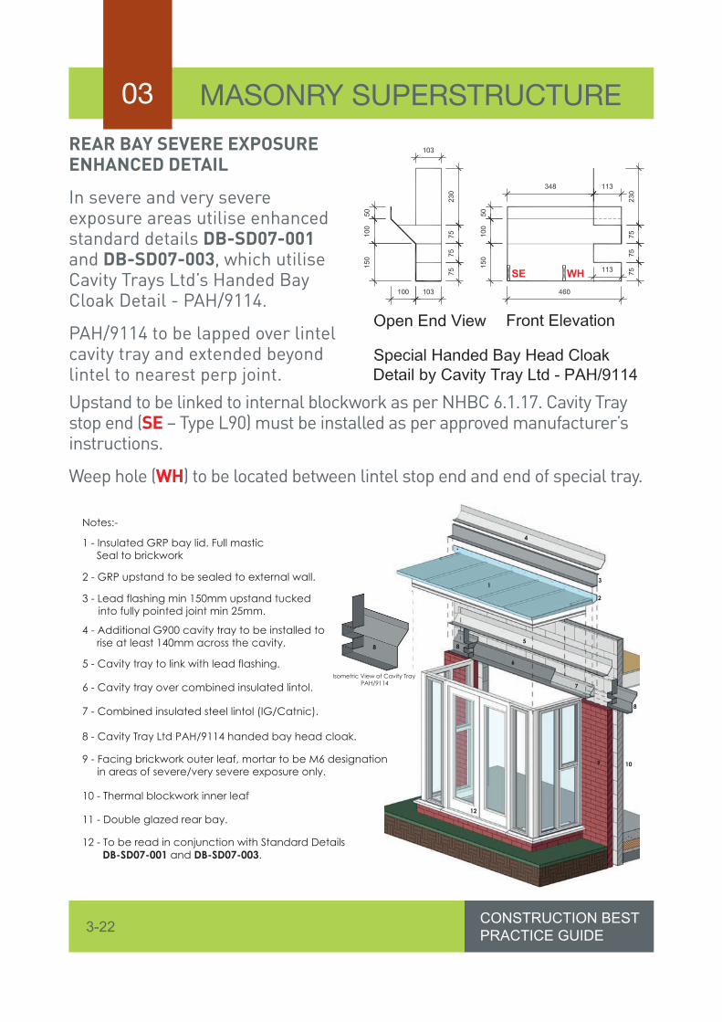
MASONRY SUPERSTRUCTURE03REAR BAY SEVERE EXPOSURE ENHANCED DETAIL
In severe and very severe exposure areas utilise enhanced standard details DB-SD07-001 and DB-SD07-003, which utilise Cavity Trays Ltd’s Handed Bay Cloak Detail - PAH/9114.
PAH/9114 to be lapped over lintel cavity tray and extended beyond lintel to nearest perp joint. Upstand to be linked to internal blockwork as per NHBC 6.1.17. Cavity Tray stop end (SE – Type L90) must be installed as per approved manufacturer’s instructions.
Weep hole (WH) to be located between lintel stop end and end of special tray.
SE WH
1
4
3
5
6
7
8
8
9
12
2
10
8
Isometric View of Cavity TrayPAH/9114
Notes:-
1 - Insulated GRP bay lid. Full masticSeal to brickwork
2 - GRP upstand to be sealed to external wall.
3 - Lead flashing min 150mm upstand tuckedinto fully pointed joint min 25mm.
4 - Additional G900 cavity tray to be installed to rise at least 140mm across the cavity.
5 - Cavity tray to link with lead flashing.
6 - Cavity tray over combined insulated lintol.
7 - Combined insulated steel lintol (IG/Catnic).
8 - Cavity Tray Ltd PAH/9114 handed bay head cloak.
9 - Facing brickwork outer leaf, mortar to be M6 designationin areas of severe/very severe exposure only.
10 - Thermal blockwork inner leaf
11 - Double glazed rear bay.
12 - To be read in conjunction with Standard Details DB-SD07-001 and DB-SD07-003.

3-23CONSTRUCTION BESTPRACTICE GUIDE
MASONRY SUPERSTRUCTURE 03
Where required dentil course and other brick details should be carefully constructed to give the required affect.
Fully pointed corbel, with equal steps in brickwork. Use solid bricks to avoid exposing holes/frogs. Overhang never to exceed one third of a brick.
Utilising a bell cast bead and attention to detail in workmanship ensures clean, crisp junction between render and dentil courses.
Considerations for Feature Details
Voussoir heads add architectural interest feature where required. Preformed offsite versions ensure accuracy and speed when constructing complex brickwork details.

3-24 CONSTRUCTION BESTPRACTICE GUIDE
MASONRY SUPERSTRUCTURE03
Removal of waste from platforms is either via a waste chute to a skip at ground level, or mini-skips which are placed upon the loading bays, or on skip bays.
Preformed Voussoir heads to be installed when constructing brickwork and pointed to match site mortar.
Consider purpose designed on plot truss racks.
When working on upper floors/roof consider restricting access to ground floor – two transom tubes across the entrance are an effective way of doing this.

3-25CONSTRUCTION BESTPRACTICE GUIDE
MASONRY SUPERSTRUCTURE 03
Clear scaffold, with toe boards and brick guards correctly installed. All scaffolds must be set out so that working platforms are close boarded and where reasonably practicable there are no excessive gaps.
Ensure guardrail is installed at a maximum height 950mm with a gap of no more than 470mm, and all handrails attached using load bearing double couplers.
Ladders must be adequately secured, to prevent sideways and outwards movement, at the correct angle of 75° and extend 1m above any landing point.
All ladders must be positioned on suitable hard standing and where practicable, on the opposite elevation to the loading bay, as defined by the site strategy plan. In all cases the base of the ladder must be a minimum of two bays away from the loading bay.

3-26 CONSTRUCTION BESTPRACTICE GUIDE
MASONRY SUPERSTRUCTURE03
Maximum loading signs must be supplied and fixed to the loading bay by the scaffolder.
Loading bay gates must offer protection to the workforce when the gate is both opened and closed. Brick guards, toe boards and a minimum of 2no guardrails to the internal edge.
The Contractor must provide a system of identifying incomplete working platforms.
Scaffold incomplete signage to be clearly displayed near the ladder point.
All loading bays must be constructed to a detailed design. This includes garage construction where the main loading bay cannot be utilised.

3-27CONSTRUCTION BESTPRACTICE GUIDE
MASONRY SUPERSTRUCTURE 03
Good plot access maintained through scaffold.Ensure scaffold end caps are installed wherever the scaffold could come into contact with the facework.
If waste chutes are used to transfer waste to ground level a proprietary hopper at the top of the chute must be used. The hopper must be secured to the scaffolding with proprietary clamps.
Final lift within 450mm of underside of eaves/soffit for roof space operatives and roof tilers.Working platform to be within
900mm of top of decking whilst fitting joists and flooring.


