Scratches Detection of Optical Fiber Connector Based on ... · 8 Metallurgical and Mining Industry...
8
Metallurgical and Mining Industry 8 No. 7— 2015 Automatization Scratches Detection of Optical Fiber Connector Based on Wavelet Packet and Machine Vision Zhen Zhang Zhengzhou Institute of Aeronautical Industry Management, Zhengzhou 450015, Henan, China Fang Liu Henan Medical College, Zhengzhou 451191, Henan, China Abstract The important meaning of the optical fiber connector scratches detection was introduced based on wavelet packet and machine vision. To detect the optical fiber connector scratches by using the Ul- traPAC system, aiming at the scratches feature, the method of analyzing and extracting the scratches eigenvalue by using wavelet packet analysis and pattern recognition by making use of the wavelet neural network is discussed. This method can realize to extract the interrelated information which can reflect optical fiber connector scratches feature from the ultrasonic information being detected and analysis it by the information. Construct the network model for realizing the qualitative scratch- es detection. The results of experiment show that the wavelet packet analysis adequately make use of the information in time-domain and in frequency-domain of the optical fiber connector scratches echo signal, multi-level partition the frequency bands and analyze the high-frequency part further which don’t been subdivided by multi-resolution analysis, and choose the interrelated frequency bands to make it suited with signal spectrum. Thus, the time-frequency resolution is risen, the good local amplificatory property of the wavelet neural network and the study characteristic of multi-res- olution analysis can achieve the higher accuracy rate of the qualitative classification of optical fiber connector scratches detection. Finally, the studies are described about detection method of the opti- cal fiber connector scratches based on machine vision. Key words: MACHINE VISION, OPTICAL FIBER CONNECTOR, SCRATCHES DETECTION, WAVELET PACKET 1. Introduction Optical fiber connector, as the necessary equip- ment which connects two optical fibers, its surface scratches can make a head high loss when light signal that transmit in optical fiber through optical fiber con- nector and affect the performance of the optical fiber network. The traditional method of optical fiber con- nector surface scratches detection, mainly complet- ed by artificially responsible for, has been unable to meet demand. In recent years, the system of product surface scratches detection based on machine vision technology by its fast detection speed, high precision, no damage, and many other advantages plays a more and more important role in the modern
Transcript of Scratches Detection of Optical Fiber Connector Based on ... · 8 Metallurgical and Mining Industry...
Metallurgical and Mining Industry8 No. 7— 2015
Automatization
Scratches Detection of Optical Fiber Connector Based on Wavelet Packet and Machine Vision
Zhen Zhang
Zhengzhou Institute of Aeronautical Industry Management, Zhengzhou 450015, Henan, China
Fang Liu
Henan Medical College, Zhengzhou 451191, Henan, China
AbstractThe important meaning of the optical fiber connector scratches detection was introduced based on wavelet packet and machine vision. To detect the optical fiber connector scratches by using the Ul-traPAC system, aiming at the scratches feature, the method of analyzing and extracting the scratches eigenvalue by using wavelet packet analysis and pattern recognition by making use of the wavelet neural network is discussed. This method can realize to extract the interrelated information which can reflect optical fiber connector scratches feature from the ultrasonic information being detected and analysis it by the information. Construct the network model for realizing the qualitative scratch-es detection. The results of experiment show that the wavelet packet analysis adequately make use of the information in time-domain and in frequency-domain of the optical fiber connector scratches echo signal, multi-level partition the frequency bands and analyze the high-frequency part further which don’t been subdivided by multi-resolution analysis, and choose the interrelated frequency bands to make it suited with signal spectrum. Thus, the time-frequency resolution is risen, the good local amplificatory property of the wavelet neural network and the study characteristic of multi-res-olution analysis can achieve the higher accuracy rate of the qualitative classification of optical fiber connector scratches detection. Finally, the studies are described about detection method of the opti-cal fiber connector scratches based on machine vision.Key words: MACHINE VISION, OPTICAL FIBER CONNECTOR, SCRATCHES DETECTION, WAVELET PACKET
1. IntroductionOptical fiber connector, as the necessary equip-
ment which connects two optical fibers, its surface scratches can make a head high loss when light signal that transmit in optical fiber through optical fiber con-nector and affect the performance of the optical fiber network. The traditional method of optical fiber con-
nector surface scratches detection, mainly complet-ed by artificially responsible for, has been unable to meet demand. In recent years, the system of product surface scratches detection based on machine vision technology by its fast detection speed, high precision, no damage, and many other advantages plays a more and more important role in the modern
9Metallurgical and Mining IndustryNo. 7— 2015
industrial automation production.Optical fiber communication technology is a new
technology with rapid development in recent 20 years, which is an important symbol of globe new technol-ogy revolution. With incessant perfecting technique and sharply falling price, the application of optical fiber become wide increasingly in communication field. The method of pattern recognition to optical fib-er scratches based on machine vision will be analyzed and discussed in this paper.
2. Scratches detection and detection method2.1 Scratches detection of optical fiber connec-
torThe evaluation parameters of optical fiber quality
include reflection loss, curvature radius, connection loss, dip angle migration, etc[1]. The connection loss is constituted mainly by intrinsic loss and fusion loss, which influence directly the transmission quality of optical fiber communication system. According to standard of ANSI/EIA/TIA-455-59, the maximum of luminous decay must less than 0.3dB in the project of FTTx. So classification and recognition of the optical fiber connector scratches is a significant problem to engineers.
2.2 Detection method and systemA great deal of information related to scratches
feature can be acquired from the echo signal of opti-cal fiber connectors through the ultrasonic detection, and the key of the classification of scratches reali-zation lies in whether it can extract the information which reflect the feature of scratches character effec-tively and give the correct explanation. Because the ultrasonic echo signals have time-varying feature, which can’t fulfill with condition of Fourier analysis in mathematics, it is difficult to gain the better spec-trum, and the spectrum can’t reflect the scratches fea-ture in time-domain. The wavelet packet has the more refined local analyzing ability and suited to analyze the ultrasonic echo signals[2]. The wavelet neural network has more powerful abilities of approximate and fault-tolerant and the realized process is simpler. So if using it in the classification of scratches can get the good result. Choosing ultrasonic detecting signal of optical fiber connectors as the research object, use wavelet packet to extract the scratches feature signals and input it into the wavelet neural network for realiz-ing the classification of scratches. The results showed that this method has good effect in the scratches rec-ognition of optical fiber connector scratches.
In this experiment the material for producing the scratches sample is 62.5/125μm single-mode fiber, and the scratches mode is operation by optical fiber connector. The hardware of the experiment system
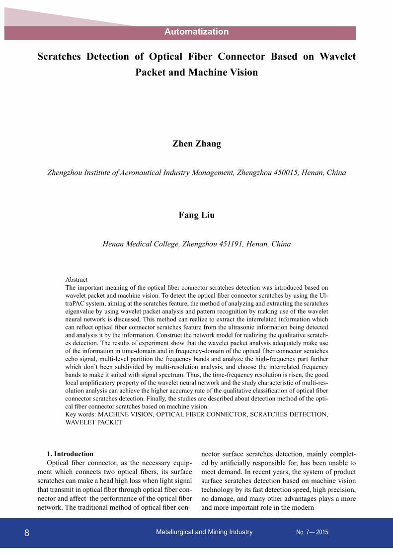
constitutes with computer system, ultrasonic detector, A/D sample card, etc. And under supporting of the application software, which can complete the mis-sions, such as the echo signal acquisition, scratches wave feature extraction and pattern classification of wavelet neural network etc, as the Figure 1 show.
Figure 1. Detection system of scratches
3. Extraction of space feature by wavelet packetThe wavelet decomposition can only decompose
further the low-frequency information and cannot decompose the high-frequency information, which make the high-frequency information cannot be use and information extracting cannot get enough. So the information decomposition is completed by wavelet packet in high-frequency bands. The differentia be-tween wavelet packet decomposition and wavelet decomposition is that wavelet packet decomposition equal to use a low-pass filter and a high-pass filter at the same time.
The wavelet packet analysis can provide a more refined analysis method, which can multi-level par-tition the frequency bands and analyze the high-fre-quency part further which don’t been subdivided by multi-resolution analysis, and choose the interrelated frequency bands to make it suited with signal spec-trum. The time-frequency resolution is rising. Thus, discussing to this experiment, we can decompose the signal subtly by wavelet packet, and realize the rec-ognition of the scratches. This paper use the pattern recognition method based on energy- defect [3].
Connector scratches signals in wavelet packet ex-press with the distinct energy distributing changing in wavelet subspace. The signal j order wavelet packet transform can get wavelet packet coefficients ,
mj kcoef ,
m=1, 2, … 2 j is the number of the wavelet tree nodes which getting after decomposing, and k is the loca-tion parameter under the wavelet packet subspace of 2 j scale. After decomposing the wavelet coefficients of N frequency bands constitute N subspaces, denot-ed as ,j nA , and the signal energy of each subspaces is
(1)
Automatization

Metallurgical and Mining Industry10 No. 7— 2015
AutomatizationConstructing feature vector by using energy as el-
ement
(2)Normalizing the eigenvector
,= ∑ j mm
E E is
(3)'( )F m is feature space being extended after nor-
malizing the eigenvector.Researching from frequency-domain, if regard the
Table 1. Frequency band of wavelet package decomposition
Wavelet packet subspace Frequency bands (MHz)
S(3,0) 0.000 ~ 6.250
S(3,1) 6.250 ~ 12.500
S(3,2) 12.500 ~ 18.750
S(3,3) 18.750 ~ 25.000
S(3,4) 25.000 ~ 31.250
S(3,5) 31.250 ~ 37.500
S(3,6) 37.500 ~ 43.750
S(3,7) 43.750 ~ 50.000
highest frequency composition within original signal as 1, the wavelet packet decomposition is decompos-ing signal with different frequency bands evenly into several windows, and each decomposed results cor-responds signal information in the frequency bands. Table1 express frequency bands partition of the 3 lay-ers wavelet packet decomposition in the experiment. Because sample frequency of ultrasonic signal is 100 MHz, the scope of frequency band is 0~50 MHz in wavelet packet decomposition.
4. Pattern recognition based on wavelet neural network
Wavelet neural network is a kind of neural network based on wavelet analysis, which make use of the good local localized character of the wavelet trans-form and combine the self-learning function of neu-ral network [4]. So wavelet neural network has more powerful abilities of approximate and fault-tolerant and the realized process is simpler. In this experiment we choose the discrete orthogonal wavelet network which is evolved from radial basis function, and its construction according to discrete wavelet transform theory as: select basis wavelet function 2( ) ( )ϕ =x L R ,
( )φ ω is ( )φ x Fourier transform, and suffice admissi-ble condition:
(4)The wavelet function system ,,{ ( )}ϕa b x can be
achieved after using scale transformation and trans-lation transform to ( )φ x ,
(5)In the formula, a is scale parameter, b is transla-
tion transform. To arbitrary function ( )f x , its defini-tion of continuous wavelet transform is
(6)
Ordering 2= ja , 2= jb k , j , ∈k Z , so binary dis-crete wavelet function is
(7)
The function ( )f x fits with coefficient ,i jC as
(8)
According to feature of optical fiber connector scratches signal, select Morlet decompose wavelet which used to detect the signal singularity at first, as
(9)
For constructing the orthogonal basis of Hilbert space, the scale coefficient sequence { }nh and wavelet coefficient sequence { }ng are confirmed by the con-struction condition of compactly supported wavelet. Knowing from wavelet theory, when scale coefficient j is large enough, the feed-forward network, which
includes one hidden layer can approximate a nonlin-ear mapping with arbitrary function. So we make use of three layers wavelet network in this experiment.
11Metallurgical and Mining IndustryNo. 7— 2015
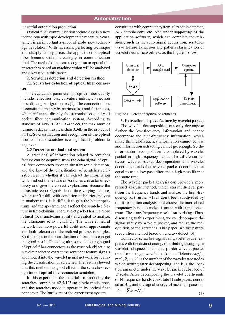
Automatization5. Recognition of defect wave characteristic5.1 Ultrasonic detection of optical fiber connec-
torThe ultrasonic flaw detector adopting in exper-
iment is the ultrasonic feature and imaging system made in Physical Acoustics Corporation of USA. UltraPAC system is ultrasonic scanning imaging sys-tem of integrative computer and digitization, which is constituted by following few parts: the ultrasonic signal collecting hardware, dipping scanning support
and actions control hardware, data collecting soft-ware, the system controller, ultrasonic sensor and attachments etc[5]. The signal of upper surface and nether surface, which are detected along the direction of ultrasonic detecting, are eliminated from the col-lecting signals. These signals are analyzed after its length change into 128 though symmetrical spread process. The wave-shape of scratches ultrasonic sig-nal after processing showed as Figure 2, 3 and 4.
Figure 2. Waveshape of non-scratches signal Figure 3. Waveshape of low scratches signal
Figure 4. Waveshape of high scratches signal
5.2 Wavelet packet decomposingAccording to the pattern recognition method of
energy- defect, the scratches ultrasonic signals from detecting are carried on decomposing of 3 layers wavelet packet firstly, extracting respectively charac-teristic signals of the third layer is from 8 frequency bands between low frequency part and high frequency part. The characteristic extraction of scratches signal and non-scratches signal were shown as Figure 5, 6.
Reconstructing wavelet packet decomposition co-efficient of the third frequency band, after extracting the time-domain signal, the total energy of the optical fiber connector can be gained and construct eigenvec-tor finally. After wavelet transform, the reconstruc-tion signals of each frequency parts, eigenvector of non-scratches, low scratches and high scratches were
shown in Table 2, 3 and 4.5.3 Pattern recognition resultEach scratches echo acquired by ultrasonic detect-
ing was a sample, and total 36 samples. Extracting characters by using energy change of every frequency parts, which is input mode vector of wavelet neural network. In the 42 signals 14 signals are non-scratch-es signal, 14 signals are low scratches signal and the other 14 signals are high scratches signal. These signals are separated random two parts, one part of which with 21 samples makes use of exercising net-work and the other one part 21 signals make use of network capability testing. In this research, the input layer contains 8 neurons which represent 8 eigenval-ues. The output layer contains 3 neurons which repre-sent 3 output variables Y1, Y2 and Y3. Scale value of

Metallurgical and Mining Industry12 No. 7— 2015
Automatizationeach output variable only can be 0 of 1, 3 output var-iables have 3 scale value combinations which repre-sent 3 scratches conditions, such as (1,0,0) represent-ing non-scratches, (0,1,0) representing low scratches and (0,0,1) representing high scratches. The number of hidden layer nodes is 15 after confirming finally.
Knowing from the upper figures, the error con-vergence curves can be approximated to 0.001 after 2200, 1300 and 1200 training cycles about, and rather
Figure 5. Characteristic extraction of scratches signal Figure 6. Characteristic extraction of non-scratches signal
approximate the ideal output mode, which have mem-ory function and can use for testing. The recognition results of testing sample are 28 scratches samples be-ing recognized all. Knowing from confirming result, the defeat network constructing in this research have good classification effect and can complete to test the type of unknown optical fiber scratches signals[6].
Table 2. Testing signal eigenvector of non-scratches
Sample 1 2 … 8 9
E3,0 0.7537 0.8612 … 0.8246 0.7801
E3,1 0.1039 0.1442 … 0.1091 0.1225
E3,2 0.3323 0.3344 … 0.2372 0.3952
E3,3 0.1572 0.1367 … 0.0661 0.1017
E3,4 0.1423 0.0754 … 0.1309 0.2192
E3,5 0.1344 0.2209 … 0.0840 0.2817
E3,6 0.4035 0.1893 … 0.2821 0.1623
E3,7 0.2833 0.0964 … 0.3713 0.2328
Table 3. Testing signal eigenvector of low scratches
Sample 1 2 … 8 9
E3,0 0.4682 0.5743 … 0.3088 0.1907
E3,1 0.1151 0.1040 … 0.0789 0.1703
E3,2 0.2694 0.4352 … 0.2019 0.4286
E3,3 0.1939 0.2061 … 0.2127 0.4595
E3,4 0.3162 0.3138 … 0.3810 0.2734
E3,5 0.1210 0.4119 … 0.4605 0.2046
E3,6 0.5164 0.2743 … 0.5936 0.4471
E3,7 0.5212 0.2959 … 0.3223 0.4698

13Metallurgical and Mining IndustryNo. 7— 2015
AutomatizationTable 4. Testing signal eigenvector of high scratches
Sample 1 2 … 8 9
E3,0 0.2173 0.1905 … 0.3198 0.2572
E3,1 0.2989 0.4030 … 0.1157 0.2465
E3,2 0.5842 0.5471 … 0.6316 0.5269
E3,3 0.3402 0.3135 … 0.3937 0.2418
E3,4 0.2827 0.2411 … 0.1334 0.3041
E3,5 0.2791 0.1843 … 0.1562 0.2376
E3,6 0.2326 0.4320 … 0.2921 0.5833
E3,7 0.4344 0.3472 … 0.4545 0.1841
6. Simulation6.1 Influence of learning rateIn the learning process of fuzzy neural network,
the variety of the learning rate will have great influ-ence on the network training. The training scratches and subsequent verification scratches in this paper are all calculated according to the following formula. The influence of network training convergence circum-stance with the different η was listed in the Table 5.
(11)
In this formula,
(12)
Table 5. Training times for expected precision
Learning rate Sample quantity Training quantity Expected value Final value
0.01 27 214 0.005 0.00494
0.02 27 111 0.005 0.00493
0.03 27 114 0.005 0.00490
From Table 5 can get, with different learning rate, the training times of network is also different when it attains same scratches. The mainly reason is the re-vising range of network parameter will get smaller when η value is small [7]. As a result attained the certain precision will increase the training times. When the η value is big, the revising ranges of the network parameter will also getting bigger along with the reducing of the training times. The curve of net training rate in Figure7 also explains same result [8]. Certainly, if value demand can be satisfied, we should choose the bigger learning rate as far as possible to improve the network training speeds. If η value is so big, the network will appear shakes and the scratches curve will become not smooth, therefore confirm the learning rate is 0.02 based on this cause.
Figure 7. The curve of net training
6.2 Simulation resultTo select 32 samples within the training samples to
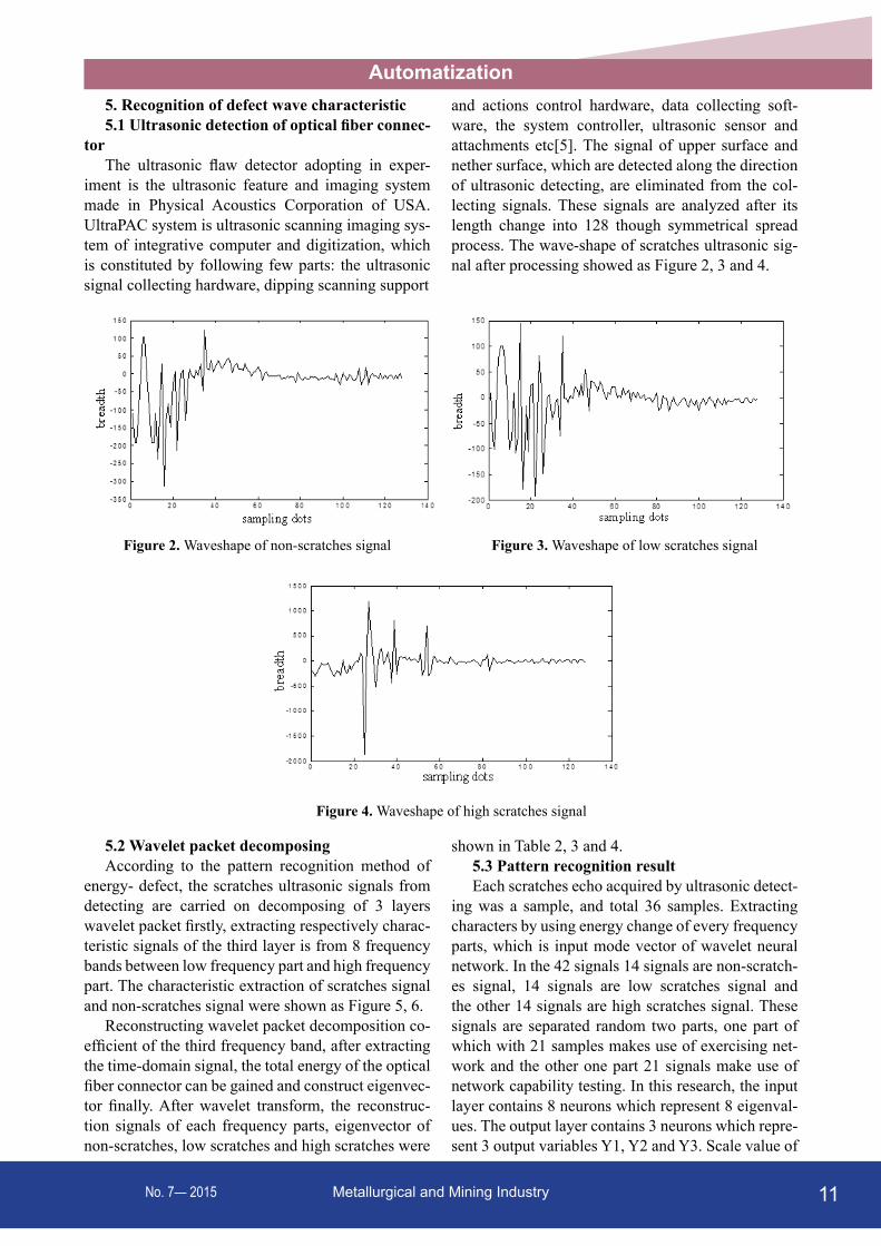
train the nerve network model of optical fiber connec-tor scratches, among them including 10 non-scratch-es signals, 8 weak bounding scratches signals and 14 lack of bounding scratches signals. After training can get the verification result showed as the Figure 8, 9 and 10.
Figure 8. Contrast between expected output to the actual output of variable 1
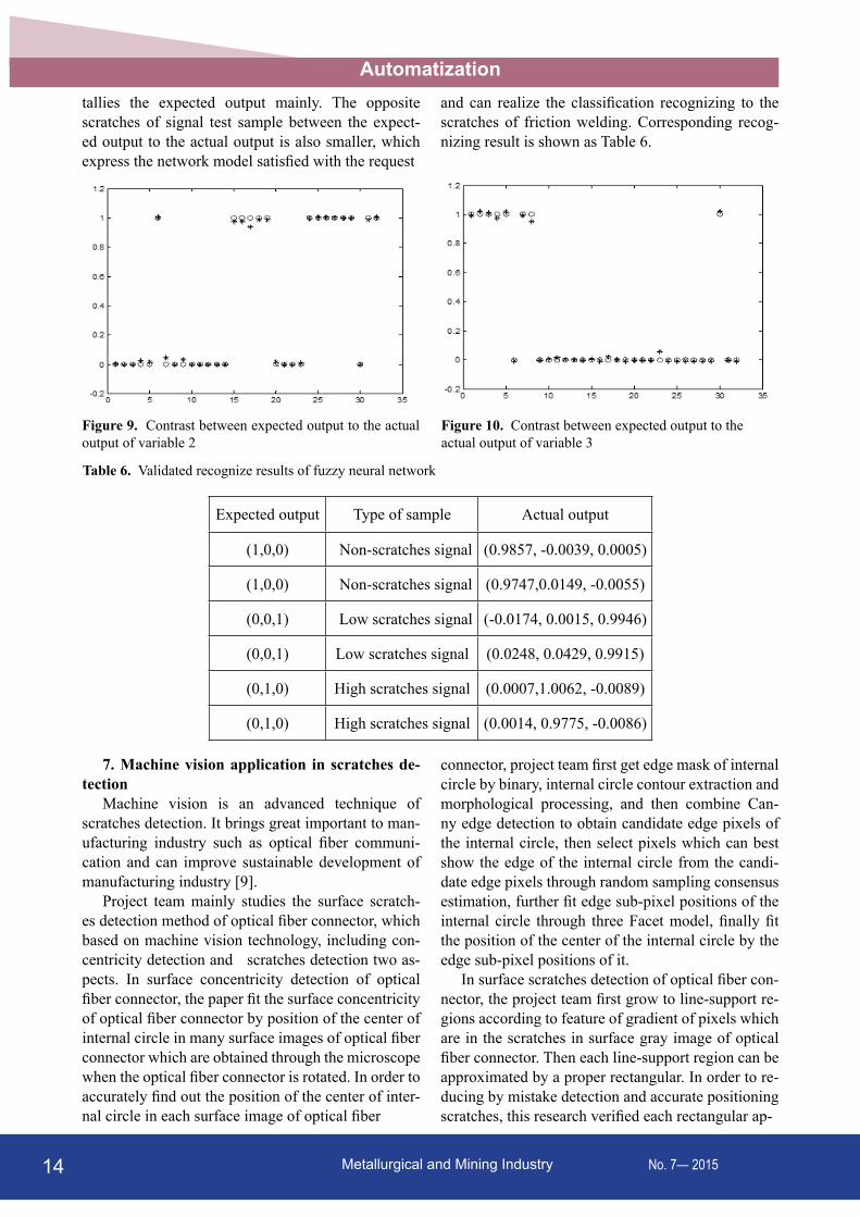
Figure 8, 9 and 10 are the three type contrast dia-grams which between the expected output to the ac-tual output, among them "o" represent the expected output, "*" represent the actual output. It’s easy to see from figures, the effect of the network integrating the training samples is quite ideal, and the actual output
Metallurgical and Mining Industry14 No. 7— 2015
Automatizationtallies the expected output mainly. The opposite scratches of signal test sample between the expect-ed output to the actual output is also smaller, which express the network model satisfied with the request
and can realize the classification recognizing to the scratches of friction welding. Corresponding recog-nizing result is shown as Table 6.
Figure 9. Contrast between expected output to the actual output of variable 2
Figure 10. Contrast between expected output to the actual output of variable 3
Table 6. Validated recognize results of fuzzy neural network
Expected output Type of sample Actual output
(1,0,0) Non-scratches signal (0.9857, -0.0039, 0.0005)
(1,0,0) Non-scratches signal (0.9747,0.0149, -0.0055)
(0,0,1) Low scratches signal (-0.0174, 0.0015, 0.9946)
(0,0,1) Low scratches signal (0.0248, 0.0429, 0.9915)
(0,1,0) High scratches signal (0.0007,1.0062, -0.0089)
(0,1,0) High scratches signal (0.0014, 0.9775, -0.0086)
7. Machine vision application in scratches de-tection
Machine vision is an advanced technique of scratches detection. It brings great important to man-ufacturing industry such as optical fiber communi-cation and can improve sustainable development of manufacturing industry [9].
Project team mainly studies the surface scratch-es detection method of optical fiber connector, which based on machine vision technology, including con-centricity detection and scratches detection two as-pects. In surface concentricity detection of optical fiber connector, the paper fit the surface concentricity of optical fiber connector by position of the center of internal circle in many surface images of optical fiber connector which are obtained through the microscope when the optical fiber connector is rotated. In order to accurately find out the position of the center of inter-nal circle in each surface image of optical fiber
connector, project team first get edge mask of internal circle by binary, internal circle contour extraction and morphological processing, and then combine Can-ny edge detection to obtain candidate edge pixels of the internal circle, then select pixels which can best show the edge of the internal circle from the candi-date edge pixels through random sampling consensus estimation, further fit edge sub-pixel positions of the internal circle through three Facet model, finally fit the position of the center of the internal circle by the edge sub-pixel positions of it.
In surface scratches detection of optical fiber con-nector, the project team first grow to line-support re-gions according to feature of gradient of pixels which are in the scratches in surface gray image of optical fiber connector. Then each line-support region can be approximated by a proper rectangular. In order to re-ducing by mistake detection and accurate positioning scratches, this research verified each rectangular ap-

15Metallurgical and Mining IndustryNo. 7— 2015
Automatizationproximating line-support region. Finally, according to the distance and direction angle of scratches, combine the scratches belonging to the same scratches into one scratch. According to the studies of surface concen-tricity detection and scratches detection of optical fib-er connector, the surface concentricity detection ex-periment and surface scratches detection experiment are implemented. And then the experiment results are carefully analyzed. The experiment results show that the surface scratches detection method of optical fib-er connector studied which based on machine vision technology, can rapidly and accurately detect the sur-face concentricity and scratches of optical fiber con-nector, and can be applied to practical projects of the surface scratches detection of optical fiber connector. Therefore, the expected purpose is reached.
8. ConclusionsExtracting characteristic value of scratches signal
based on wavelet packet transform and machine vi-sion can keep high-frequency feature of the original data petty well and make the uneasily scratches sig-nal feature can discovered in time domain with dif-ferent resolutions. Some local feature of ultrasonic signal will not disappear after wavelet transform, so the wavelet packet transform can be used an effective method for extracting feature of scratches signals.
In classification of the optical fiber connector scratches, wavelet neural network not only have very quick learning speed, but also can realize the accurate scratches recognition. The results of experiment im-prove this wavelet neural network have high accuracy rate for the scratches predicting and can satisfy the requirements of, so which can provide the powerful technical assurance for realizing optical fiber connec-tor quality detecting system further.
References1. Gioi G R, Jeremie J, Morel J M. (2010) LSD:
A Fast Line Segment Detector with a False Detection Control. IEEE Transactions on Pat-tern Analysis and Machine Intelligence, 32(4) , p.p.722-732.
2. Brian J, Allen R, Edward M. Riseman (1986) Extracting straight lines. IEEE Trans. PAMI, 8(4) , p.p.425-455.
3. Ballard D H. (1981) Generalizing the hough transform to detect arbitrary shapes. PR, 13(2), p.p. 111 -122.
4. Desolneux A, Ladjal S, Moisan L, et al. (2002) Dequantizing image orientation. IEEE Transactions on Image Processing, 11(10) , p.p.1129-1140.
5. Gioi G R, Jakubowicz J, Morel J M,et al. (2008) Lsd: A line segment detector. Technical report, CMLA, ENS-CACHAN.
6. Gioi G R, Jakubowicz J, Randall G. (2007) Multisegment detection. Proc. of ICIP 2007.
7. Ji C X, Zhang Z P. (1988) Stereo match based on linear feature. In ICPR88, p.p.875–878.
8. Kahn P, Kitchen L, Riseman E M. (1987) Re-al-time feature extraction: A fast line find-er for vision-guided robot navigation. COINS, Technical Report, p.p.57-87.
9. P. Kahn, L.Kitchen, E. M. (1990) Riseman.A fast line finder for vision-guided robot naviga-tion. IEEE Transactions on Pattern Analysis and Machine Intelligence, 12(11), p.p.1098-1102.
AcknowledgementsThis work was supported by the Youth Science
Research Fund of Zhengzhou Institute of Aeronauti-cal Industry Management (Grant No. 2014133001).