Science Mission Configuration Management Plan · PDF fileCDR - Critical Design Review CM ......
34
P0098 Rev B Page 1 W. W. Hansen Experimental Physics Laboratory STANFORD UNIVERSITY STANFORD, CALIFORNIA 94305-4085 Gravity Probe B Relativity Mission Science Mission Configuration Management Plan P0098 Rev B July 19, 2001 Contract No. NAS8-39225 ____________________________ Dorrene M. Ross System Effectiveness Manager _________________________________ Bob Schultz Chief System Engineer _________________________________ Barry Muhlfelder Program Technical Manager _________________________________ Bill Bencze Payload Electronics Manager _________________________________ Rob Brumley Payload Technical Manager _________________________________ Gaylord Green Spacecraft Manager _________________________________ Professor Sasha Buchman Program Manager
-
Upload
trinhxuyen -
Category
Documents
-
view
216 -
download
3
Transcript of Science Mission Configuration Management Plan · PDF fileCDR - Critical Design Review CM ......

P0098 Rev B Page 1
W. W. Hansen Experimental Physics Laboratory STANFORD UNIVERSITY
STANFORD, CALIFORNIA 94305-4085
Gravity Probe B Relativity Mission
Science Mission Configuration Management Plan
P0098 Rev B July 19, 2001
Contract No. NAS8-39225
____________________________ Dorrene M. Ross System Effectiveness Manager _________________________________ Bob Schultz Chief System Engineer _________________________________ Barry Muhlfelder Program Technical Manager _________________________________ Bill Bencze Payload Electronics Manager _________________________________ Rob Brumley Payload Technical Manager _________________________________ Gaylord Green Spacecraft Manager _________________________________ Professor Sasha Buchman Program Manager

P0098 Rev B Page 2
Document Revision Record
Document Title: Stanford University, Gravity Probe B Relativity Mission, Science Mission Configuration Management Plan
Document Number: P 0098, Rev B
Document Approved By NASA/MSFC:
Release Date:
REV Date Authorization
for Change -
ECO #
Page Paragraph Change Description
A 2/29/00 1059 All Re-written.
B 7/19/01 1285 3 5.1.3, 5.2.4, 5.2.5
Additions and clarifications.
4 8.4 Add.
7 3.0 Add SOW.
8 4.3, 4.5 Clarifications.
9 4.6, 4.8 Clarifications.
10 5.1.1 Clarification.
11, 12 5.1.3 Additions and clarifications.
14 5.3.1 Addition of paragraph 5.3.1.
21 5.3.3.3 Clarifications.
22 5.3.3.5 Clarifications.
23 8.1, 8.4 Clarifications and additions.
P0098 Rev B Page 3
Table of content 1. Scope and summary 6 2. Applicable Documents 6 3. Acronyms 6 4. Organization 7
4.1 Program Manager 7 4.2 Spacecraft Manager 7 4.3 Program Technical Manager 7 4.4 Payload Electronics Manager 8 4.5 Payload Technical Manager 8 4.6 Deputy Program Manager 9 4.7 Chief Systems Engineer 9 4.8 System Effectiveness Manager 9 4.9 Responsible Design Engineers 9
5. Configuration Management Practice for Documents 10 5.1 Establishing the Baseline 10
5.1.1 Establishing the Baseline for Specifications/Requirements 10 5.1.2 Establishing the Baseline for Procedures 10
5.1.3 Establishing the Baseline for Science Documents 11 5.1.4 Establishing the Baseline for Drawings 12 5.1.5 Establishing the baseline for Software 12 5.1.6 Establishing the Baseline for Interface Control Documents 12
5.2 Establishing the Release Process 12 5.2.1 Drawing Release Process 12 5.2.2 The Drawings List/Procedures List and Specifications List 13 5.2.3 Drawing Tree 13
5.3 Change Process 14 5.3.1 Change to Science Documents 14
5.3.2 Changes Classification and Definition 15 5.3.2.1 Type I Change 15
5.3.2.2 Type II Change 15 5.3.3 Change Boards 16
5.3.3.1 NASA Headquarters CCB (Level I) 17 5.3.3.2 MSFC CCB (Level II) 17 5.3.3.3 SU Program Control Board PCB (Level III) 17 5.3.3.4 PCB Screening Committee 17 5.3.3.5 SU Engineering Change Orders (Level III) 18 5.3.3.6 LMMS ECB (Level IV) 19
5.3.4 Authorities, Responsibilities and the Processes for Changes 19
P0098 Rev B Page 4
5.3.4.1 Type I Changes 19 5.3.4.2 Type II, Class 1 Changes 20 5.3.4.3 Type II, Class 2 Changes 20
5.3.4.4 Type II, Class 2 Minor Changes 21 5.3.4.5 Changes at Sub-Contractors
21 6. Configuration Management for Product 22
6.1 Product Identification 22 6.1.1 Hardware Identification 22 6.1.2 Software Identification 22
6.2. As-Built Configuration 22 6.2.1 Hardware As-Built Configuration 22 6.2.2 Software As-Built Configuration 23
7. Audits 23 8. Configuration and Test Database 23
8.1 Specifications 23 8.2 Program Control Board 23 8.3 Procedures 23 8.4 Science Documents 23 8.5 Drawings 23 8.6 Component 24 8.7 Drawing Trees 24 8.8 Engineering Change Order (ECO) 24 8.9 As-Built Configuration 24

P0098 Rev B Page 5
Appendix List A. GP-B Organization Chart B. Example of GP-B Drawing Tree C. Example of Procedure Cover Sheet D. Example of Test Procedure Cover Sheet E. Example of Drawing Approval Form F. Program Control Board Change Request Form G. Example of Engineering Change Order Log H. Example of Engineering Change Order Form I. Kit List/As Built Configuration List
P0098 Rev B Page 6
1. Scope and summary
The Configuration Management Plan covers Configuration Management of Program Requirements, Design Requirements, and Product Configuration for the GP-B experiment defined in T001. The top level Program Requirements are described in T002, "12 Science Requirements" and T003, "System Design and Performance Requirements". The Program's Requirements Tree is maintained in the GP-B Configuration & Test Database. The Design Requirements include all the drawings, procedures and specifications related to the Science Mission. The drawings are
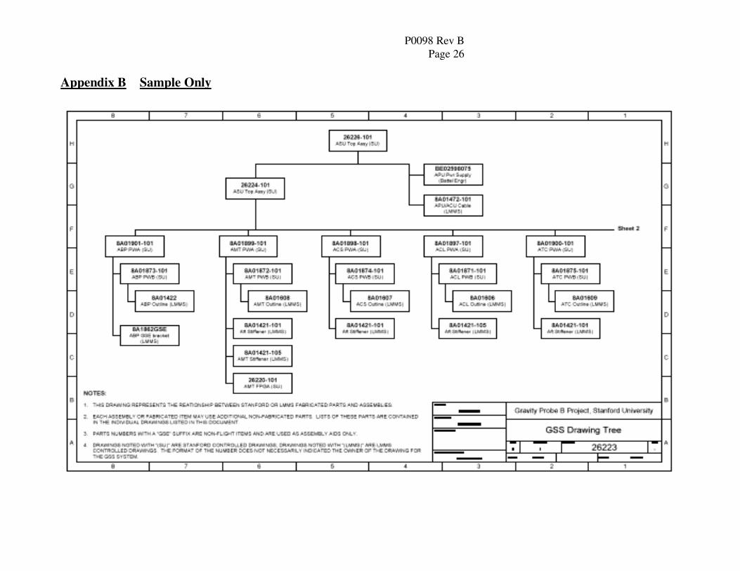
detailed in the program's Drawing Trees. See Appendix B for a sample of a GP-B Drawing Tree. The Product Configuration includes the As-Built Configuration of the hardware and software for the program.
The purpose of this plan is to describe the procedures for the control of the items mentioned above through the development and build of the Relativity Mission. The plan includes a description of authorities/responsibilities, establishing of baselines, use of redlines, the processes for implementation of changes, identification of hardware and software, and the process for As-Built Configuration Control.
2. Applicable Documents
2.1 T001, “Science Mission Objectives” 2.2 T002, “12 Fundamental Science Requirements” 2.3 T003, “System Design Performance Requirements” 2.3 DOD-D-1000, Drawings, Engineering and Associated Lists 2.4 DOD-STD-100, 2.5 SE 08 Volume 1, LMMS “Software Management Plan” 2.6 SU P0630, “Software Quality Assurance Plan” 2.7 GP-B Configuration and Test Database, Design Specification, 8/31/94.
(located on the GP-B server)
3. Acronyms
CCB - Configuration Control Board CDR - Critical Design Review CM - Configuration Management CSE - Chief Systems Engineer ECB - Engineering Change Board ECO - Engineering Change Order ICD - Interface Control Document ID - Identification Number LSEE - Lockheed Software Engineering Environment LMMS – Lockheed Martin Missiles and Space MSFC - Marshall Space Flight Center MRB - Material Review Board PCB - Program Control Board PDR - Preliminary Design Review
P0098 Rev B Page 7
RE - Responsible Engineer SM - Science Mission SOW – Statement of Work SRR - System Requirement Review SU - Stanford University
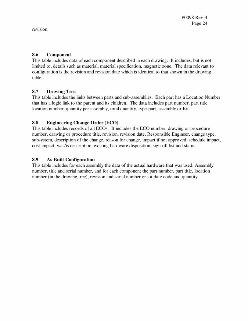
4. Organization The GP-B Organization Chart is shown in Appendix A.
The responsibility and role of each member is described hereafter:
- The prime responsibility for SM Configuration Management is vested in the SM Program
Manager.
- The SM Program Manager is assisted by the System Effectiveness Manager, who also
serves as the Configuration Manager, and other persons assist as described herein.
4.1 Program Manager
The Configuration Management (CM) functions of the Program Manager include:
- Chairman of SU's PCB.
- Chairman of SU's Class 1 Major ECB for Science Instrumentation.
- To forward Major PCBs to MSFC for approval.
- To ensure throughout the life of the program that there shall be sufficient personnel and
resources to support and meet the program objectives.
4.2 SU Spacecraft Manager
The Configuration Management functions of the Spacecraft Manager are:
- Member of SU's PCB.
- Chairman of SU's Class 2 Major ECB for Spacecraft and Software.
- Responsible for implementation of the Configuration Management Procedures for the SU
Software Modules. This includes change control of Integration and Tests Procedures
and As-Built Configuration requirements for Spacecraft and Software.
4.3 SU Program Technical Manager The Configuration Management functions of the Program Technical Manager are:
- Member of SU's PCB.
- Chairman of SU's Class 2 Major ECB for Non-Electronics portions of the Science
Instrumentation.
- Member of MRB.
- Responsible for implementation of the Configuration Management Procedures for the
P0098 Rev B Page 8
SU Program Specification Documents. This includes change control of Specification
Science Documents (SDOCs) as they apply to the program.
4.4 SU Payload Electronics Manager The Payload Electronics Manager is responsible for the Gyro Suspension Units, SQUID Readout Electronics, Telescope Readout Electronics, the Experimental Control Unit, the Global Positioning System, Proton Monitor, Payload Magnetometer, Payload Wire Harness, Grounding, Shielding and EMI Control. The CM responsibilities and roles of the Payload Electronics Manager are:
- Member of SU's PCB.
- Chairman of SU's Class 2 Major ECB for Electronics.
- Chairman of SU's Drawing Release Board for the electronics listed above. Responsible
for approval of Engineering Change Orders for Class 2 Minor Changes to Electronics.
- To ensure that the Electronics Engineering Group complies with the Document Release
(Drawings and Procedures) and Engineering Change procedures.
- To present the Electronics Engineering position concerning Major Changes, and identify
the critical manufacturing processes that need configuration control.
- Responsible for implementation of the Configuration Management Procedures by the
Electronics Engineering group. This includes change control of Integration and Tests
Procedures, Parts Identification and As-Built Configuration requirements for Payload
Electronics Systems.
4.5 SU Payload Technical Manager The Payload Technical Manager is responsible for all Non-Electronics Payload Sub-Systems. The CM responsibilities and roles of the Payload Technical Manager are:
- Member of SU's PCB.
- Chairman of SU's Drawing Release Board for Non-Electronics.
- Responsible for approval of Engineering Change Orders for Class 2 Minor Changes to
Non-Electronics.
- To ensure that the Engineering Group complies with the Document Release (Drawings
and Procedures) and Engineering Change procedures for non-electronics.
- To present the engineering position concerning Major Changes, and identify the critical
manufacturing processes that need configuration control.
- Responsible for implementation of the Configuration Management Procedures by the
Engineering group. This includes change control of Integration and Tests Procedures,
Parts Identification and As-Built Configuration requirements for Non-Payload Electronics
Systems.
P0098 Rev B Page 9
4.6 SU Deputy Program Manager
The CM responsibility of the Deputy Program Manager is to ensure that Sub-Contractors utilize a
documented CM system for all contracts, procurement, engineering, design services and/or the
delivery of hardware and software for the SM Program. He/she is also responsible for the
archiving of all controlled documents at SU.
- Member of the PCB.
4.7 SU Chief Systems Engineer
The Chief Systems Engineer or his/her designee is:
- Member of the PCB.
- Responsible for the follow up of the PCB Requests.
- Responsible for the management of the Requirements, Specifications/Requirements
Verification and Action Items from Reviews (Monthly, Independent Reviews, SRR,
PDR, CDR,… etc.).
4.8 SU System Effectiveness Manager
The System Effectiveness Manager is responsible for all Quality activities, including the archiving
of all controlled documents at SU and the following:
- Member SU's PCB.
- Member of Drawing Release Board.
- Responsible for Quality approval of Engineering Change Orders.
- Write/review the Configuration Management Plan and configuration related procedures.
- Monitors the implementation of these procedures at SU and subcontractors.
4.9 Responsible Design Engineers The Responsible Design Engineers are:
- Members of SU’s ECB for Type II Changes that are relevant to the system they are responsible for.
- Responsible for evaluating the effect of a proposed change on system's function, cost and schedule to be presented in the ECO.
- Responsible to ensure that all drawings drafted by their group meet the engineering
drafting standards.
- Member of Drawing Release Board for relevant drawings.

P0098 Rev B Page 10
5. Configuration Management Practice for Documents
5.1 Establishing the baseline
5.1.1 Establishing the baseline for Specifications/Requirements
The relevant Requirements and their hierarchy are described in the Program's Requirements Tree stored in the GP-B Configuration & Test Database located on the SU GP-B server.
NASA Headquarters will approve the baseline of the Program’s Objectives, document T001. MSFC will approve the baseline of the Program's Science Requirements, documents T002. T001 and T002 Requirements are shown in the Database under “Documents” and then subcategory “Specifications”. (Reference GP-B “Contractor’s Documents Requirements List”; PM, PA, SE, IT, MO and SA) All Lower Requirements (T003) and Specifications will be released through the Drawing Release Process described in paragraph 5.1.3.1 5.2.1. The list of the Released Specification will establish the Baseline for Lower Specification. This list is stored in the GP-B Configuration & Test Database located on the SU GP-B server under “Documents” and then subcategory “Specifications”. The release process is as follows: 1. Specification shall have a cover sheet (similar to a Operations and Integration Procedure, see
Appendix C), signed and dated by the minimum of the persons listed below, the author of the document, the System Effectiveness Manager, and the Program Technical Manager.
NOTE: This requirement becomes effective once this procedure is approved. All changes to
the existing database documents will reflect an SDOC number in addition to the original
specification number.
5.1.2 Establishing the Baseline for Procedures
SU's Procedures describe special processes used in the program such as; Cleaning, Magnetic Screening, Lapping, Assembly, Integration, Testing and so on and are referenced in parts drawings, assembly drawings, travel sheets and test plans. The list of the Released Procedures will establish the Baseline for Procedures. This list of Procedures is stored in the GP-B Configuration & Test Database shown under “Documents” and then subcategory “Procedures”, along with their electronic copies (when available). Procedure numbers are in sequential order and are provided by and maintained by the Document Control Center.
The release process is as follows: 1. Operation and Integration Procedures shall have a cover sheet signed and dated by the minimum
of the persons listed below, see Appendix C - The author of the procedure, the Responsible Engineer (RE), the System Effectiveness
Manager, the appropriate Payload Manager and when required by the Safety Engineer.
2. Test Procedures shall have a cover sheet signed and dated by the minimum of the persons listed
below, see Appendix D.
P0098 Rev B Page 11
- The author of the procedure, the Responsible Engineer (RE), the Chief System Engineer, the System Effectiveness Manager, the appropriate Payload Manager and when required the Safety Engineer.
3. All Procedures that are contract required must be approved by MSFC, i.e. the Quality Plan, Configuration Plan, etc.
- MSFC approval will be added to the cover sheet. 4. Some procedures may be approved by ‘no-response’ with a specified time, the GP-B
Configuration & Test Database will have in the Procedure Table the following fields: MSFC approval required (Yes/No), Date submitted to MSFC, MSFC approval (either date of approval or note “approved since no response within X days the number of days as defined by contract”).
5.1.3 Establishing the Baseline for Science Documents
“Science Documents” describe software content, configuration control, methodology, test readiness, analysis, and requirements specifications. There are two types of SDOCs; those that define specification requirements and those that do not. The initial release process is the same for both types of SDOCs. The definition of types, maintenance, control and revision of these documents are as follows: 1. All SDOCs that define “specifications” (for example S0457/MO-02, Mission Operations
Specifications) will be maintained in the GP-B Configuration & Test Database located on the SU
GP-B server under “Documents” and then subcategory “Specifications”. All specification type
SDOCs are numbered in sequential order (such as MO-01, MO-02, etc.) when stored in this
database. A link to the SDOC number will be shown in database for each specification type
document. The signed off hard copy will maintained by the Document Control Center. The
electronic copy will be stored in the GP-B Configuration & Test Database located on the SU GP-
B server under “Documents” and then subcategory “Science Documents”.
NOTE: This requirement becomes effective once this procedure is approved. All changes to
the existing database documents will reflect an SDOC number in addition to the original
specification number.
2. All other SDOCs will be reviewed and approved by the individuals listed on the cover page. The
signed off hard copy will be maintained by the Document Control Center. The electronic copy will be stored in the GP-B Configuration & Test Database located on the SU GP-B server under “Documents” and then subcategory “Science Documents”.
The release process is as follows: 1. Science Document shall have a cover sheet signed and dated by the minimum of the persons
listed below, see Appendix C - The author of the procedure, the Responsible Engineer (RE), the Chief System Engineer
P0098 Rev B Page 12
or designee, the System Effectiveness Manager, the appropriate Payload Manager and any other individual as deemed necessary by the author.
2. All SDOCs that are written as specifications must be approved by MSFC, i.e. the GPS Specification, etc.
- SU shall submit to MSFC for approval. 3. Some procedures may be approved by ‘no-response’ with a specified time, the GP-B
Configuration & Test Database will have in the Procedure Table the following fields: MSFC approval required (Yes/No), Date submitted to MSFC, MSFC approval (either date of approval or note “approved since no response within the number of days as defined by contract”).
5.1.4 Establishing the Baseline for Drawings
Drawing Baseline includes Drawing Release Process, Drawing List and Drawing Tree. Drawing practices will be per DOD-D-1000 Level 2 and DOD-STD-100. Drawing numbers are in sequential order and are provided by and maintained by the Document Control Center.
5.1.5 Establishing the baseline for Software
All the software developed and released by LMMS will be controlled using LMMS document SCSE
08, Volume I, Software Management Plan. The information controlled through this system for each
module of software includes, but is not limited to, the module’s Title, Release Status, and Revision.
The list of Released Software Modules establishes the baseline for Software.
All software developed and released by SU; the SU Software Quality Plan, P0630, will control i.e., Ground Operations, Science Data Analysis and GPS modules.
5.1.6 Establishing the Baseline for Interface Control Documents (ICD)
Interface Control Documents will be developed which define and control the interfaces between elements. ICDs will be generated by LMMS defining interfaces between SU hardware/software and LMMS hardware/software.
5.2 Release Process
The release process is described for Drawings, Procedures and Lower Level Specifications. At the completion of the each document, and prior to procurement or manufacture of flight items, drawings will be presented for review and approval.
5.2.1 Drawing Release Process
Each drawing shall be reviewed and approved by a minimum of responsible parties which include but
are not limited to the appropriate Payload Manager, who serves as the chairman, the Responsible
Design Engineer for the system, whether mechanical or electronic, and the System Effectiveness
Manager. It is the responsibility of each Payload Manager to add to the release approval of each
drawing the relevant experts to cover aspects such as magnetics, cleanliness, vacuum, integration,

P0098 Rev B Page 13
stress & dynamics, manufacturing, etc.
Release of drawings will be by signing the Drawing Approval form (Appendix E) and by the
appropriate Payload Manager signing the "Master" hard copy drawing. The signed master copy of
the released drawing will be kept in the Documentation Center which is a secured, limited access
storage location, accessible to assigned personnel only.
All "Work copies" of the master drawing will be will be issued by the Documentation Control Center
and will be identified by a red "RELEASED" stamp. When a drawing is issued from the Document
Control Center the clerk will date the day the drawing was issued to the requestor.
5.2.2 The Drawings List /Procedures List and the Specifications List
1. The Drawing List includes all the Released drawings and establishes the baseline for drawings.
This list is stored in the ‘Design Table’ in the GP-B Configuration & Test Database located on
the GP-B server.
2. The Procedures List includes all the Released Procedures and establishes the baseline for
Procedures. This list is stored in the ‘Documents Table’ in the GP-B Configuration & Test
Database located on the GP-B server.
3. The Lower Level Specifications List includes all the Released Lower Level Specifications and
establishes the baseline for Lower Level Specifications. This list is stored in the ‘Documents
Table’ in the GP-B Configuration & Test Database located on the GP-B server. Specification
numbers are in sequential order and are provided by and maintained by the Document Control
Center.
Both the Payload Technical Manager and Payload Electronics Manager are responsible for establishing and updating the Drawing List, the Procedures List and the Lower Level Specification in their individual groups.
Note: Both Payload Managers will be required to approve and sign-off on procedures that
incorporate the technical and electronics groups.
5.2.3 Drawing Tree
As the design progresses, a Drawing Tree will be prepared. The Drawing Tree will include Part
Number, Dwg #, Title, Type (Assembly/ Kit/ Part) and Quantity. See Appendix F for example of a Drawing Tree. When the design of an assembly is completed, the Drawing Tree will be released through a Drawing Release Process per paragraph 5.2.1 and will be controlled as any other released document.
P0098 Rev B Page 14
5.3 Change Process
All changes to the Specifications, Drawings and Procedures, introduced after release, will be
subjected to the following Change Control measures defined in this document. It must be noted
that Stanford University will use two methods of ‘REDLINES’.
- Redlines to drawings as a way of expediting the manufacture or procurement of flight items.
These redlines will be reviewed and approved by both the Responsible Engineer and Quality
Engineer. SU will retain the ‘Master Copy Redline’ which will carry the dated stamps of
both the RE and QE. These redlines must be incorporated via the ECO process into the
next revision release of the drawing. Quality’s final Acceptance will be to released drawings
only.
- Redlines to a procedure as a method of showing changes to an ‘As-Built’. All redlines shall
be agreed upon by the RE and QE, stamped and dated. If the procedure is to be used again,
all redlines if intended for a permanent change to the procedure must be incorporated into
the next revision release before use. ECO number for changes incorporating changes to a
procedure shall be noted by the QE on the Procedure Cover Sheet.
5.3.1 Change to Science Documents
A PCB will be use when making revision changes to all SDOCs that define specifications.
All non-specification type SDOCs will be revised in the following manner. The original approvers, their designees, or their replacements will approve revisions of all these SDOCs. The revision block will reflect all changes made to the original document.
P0098 Rev B Page 15
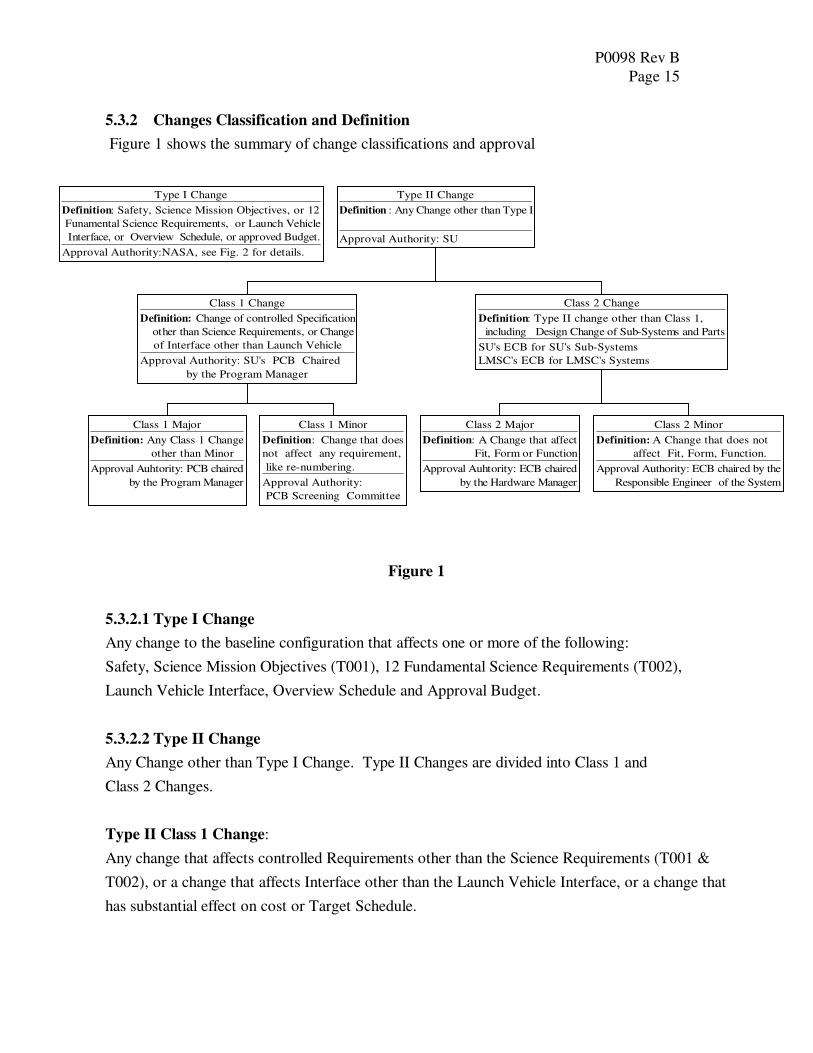
5.3.2 Changes Classification and Definition
Figure 1 shows the summary of change classifications and approval
Type I Change
Definition: Safety, Science Mission Objectives, or 12
Funamental Science Requirements, or Launch Vehicle
Interface, or Overview Schedule, or approved Budget.
Approval Authority:NASA, see Fig. 2 for details.
Class 1 Major
Definition: Any Class 1 Change
other than Minor
Approval Auhtority: PCB chaired
by the Program Manager
Class 1 Minor
Definition: Change that does
not affect any requirement,
like re-numbering.
Approval Authority:
PCB Screening Committee
Class 1 Change
Definition: Change of controlled Specification
other than Science Requirements, or Change
of Interface other than Launch Vehicle
Approval Authority: SU's PCB Chaired
by the Program Manager
Class 2 Major
Definition: A Change that affect
Fit, Form or Function
Approval Auhtority: ECB chaired
by the Hardware Manager
Class 2 Minor
Definition: A Change that does not
affect Fit, Form, Function.
Approval Authority: ECB chaired by the
Responsible Engineer of the System
Class 2 Change
Definition: Type II change other than Class 1,
including Design Change of Sub-Systems and Parts
SU's ECB for SU's Sub-Systems
LMSC's ECB for LMSC's Systems
Type II Change
Definition : Any Change other than Type I
Approval Authority: SU
Figure 1
5.3.2.1 Type I Change
Any change to the baseline configuration that affects one or more of the following:
Safety, Science Mission Objectives (T001), 12 Fundamental Science Requirements (T002),
Launch Vehicle Interface, Overview Schedule and Approval Budget.
5.3.2.2 Type II Change
Any Change other than Type I Change. Type II Changes are divided into Class 1 and
Class 2 Changes.
Type II Class 1 Change:
Any change that affects controlled Requirements other than the Science Requirements (T001 &
T002), or a change that affects Interface other than the Launch Vehicle Interface, or a change that
has substantial effect on cost or Target Schedule.
P0098 Rev B Page 16
- Type II, Class 1 Major Change:
Any Class 1 change other then a Minor.
- Type II, Class 1 Minor Change:
Changes that do not affect any requirements like correction of typo or re-numbering of
paragraphs inside the System Design and Performance Requirements.
Type II Class 2 Change:
Any change other than a Class 1 including design changes of Sub-Systems and Parts.
- Type II, Class 2 Minor Change:
Change that does not affect Fit, Form or Function at the Box Level, including changes
which will be found necessary from manufacturing considerations, during the
manufacturing of the first lot of parts or "fine tuning" of electronic boards during
assembly. Also changes of non-flight parts.
- Type II, Class 2 Major Change:
A change that affects Fit, Form or Function at the Box Level or major sub-systems such
as GMA, QBA or subcontracted work scope.
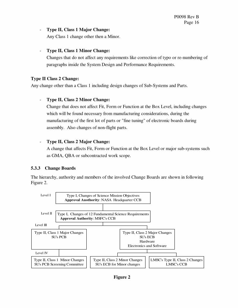
5.3.3 Change Boards
The hierarchy, authority and members of the involved Change Boards are shown in following Figure 2.
Figure 2
Level I
Level II
Level IV
Level III
Type II, Class 1 Minor Changes
SU's PCB Screening Committee
Type II, Class 1 Major Changes
SU's PCB
Type II, Class 2 Minor Changes
SU's ECB for Minor changes
LMSC's Type II, Class 2 Changes
LMSC's CCB
Type II, Class 2 Major Changes
SU's ECB
Hardware
Electronics and Software
Type I, Changes of 12 Fundamental Science Requirements
Approval Authority: MSFC's CCB
Type I, Changes of Science Mission Objectives
Approval Auothority: NASA Headquarter CCB

P0098 Rev B Page 17
5.3.3.1 NASA Headquarters CCB (Level 1)
Type 1 Changes of Science Mission Objectives shall be approved by NASA Headquarters CCB
prior to implementation.
5.3.3.2 MSFC CCB (Level II)
Type 2 Changes of 12 Fundamental Science Requirements shall be approved by the MSFC CCB
prior to implementation.
5.3.3.3 SU Program Control Board PCB (Level III)
This PCB will review and approve Type II, Class 1 Changes. The Chairman of the Board is the
SU Program Manager. Other members include the SU Program Technical Manager, SU Payload
Electronics Manager, the SU Spacecraft Manager, the Chief System Engineer, LM Program
Manager *, SU Business Manager, SU System Effectiveness Manager, SU Mission Operations
Manager, Chief Scientist and NASA Resident Manager. * Note that the LM Program Manager’s signature may indicate acknowledgement of the baseline change and not agreement with the technical implementation. The LM Program Manager’s reservations toward the technical implementation will be added to the PCB. All costs that direct LM activity will be negotiated outside the PCB process; however, all PCB’s that direct LM activity must include a rough order of magnitude (ROM) to scope the magnitude of the change impact. Experts of various disciplines and Responsible Engineers of specific systems are summoned as needed. The Deputy Program Manager is consulted when a PCB includes over $15,000 cost impact.
5.3.3.4 PCB Screening Committee
The responsibilities and authority of the PCB Screening Committee are:
- Review and verify completeness of the Change Request including the reason for change,
supporting documentation, effects if not approved, effects on other requirements,
schedule impact, cost, etc.
The Screening Committee has authority for the following:
- To reject a Change request
- To approve Class 1 Minor Changes
- To forward a change Request to the PCB with recommendation for approval
The process for generating a PCB is as follows:
1. The Chairman of the PCB Screening Committee will assign a PCB number.

P0098 Rev B Page 18
2. The initiator shall write the PCB request in the GP-B Configuration & Test Database
including the title, change details, reason for change, impacts on schedule and cost.
3. The PCB Screening Committee shall review the Change request.
4. If rejected the Change Request shall be returned to the requestor with reasons for rejection.
5. If approved the PCB members shall sign the hard copy of the Change Request. The
Chairman will mark the PCB as approved in the database. The affected documents, such as
specifications, shall also be updated in the database. The signed hard copy shall be archived
in the Documentation Center.
5.3.3.5 SU Engineering Change Orders (Level III)
Engineering Change Orders (ECO) shall be used for requests for Type II, Class 2 Changes to
hardware, electronics and software. The initiator shall write the ECO request in the GP-B
Configuration & Test Database including the title, change details, reason for change, impacts on
schedule and cost.
Changes to Hardware
- Minimum reviewers are the Payload Technical Manager (also the Chairman), the Responsible Engineer and the System Effectiveness Manager.
- If approved the ECO members shall sign the hard copy of the Change Request. The
Chairman will mark the ECO as approved in the database. The affected documents,
such as drawings, shall also be updated in the database. The signed hard copy shall be
archived in the Documentation Center.
Changes to Electronics
- Minimum reviewers are the Payload Electronics Manager (also the Chairman), the Responsible Engineer and the System Effectiveness Manager.
- If approved the ECO members shall sign the hard copy of the Change Request. The
Chairman will mark the ECO as approved in the database. The affected documents, such
as drawings, shall also be updated in the database. The signed hard copy shall be
archived in the Documentation Center.
Changes to Software
- Minimum reviewers are the Spacecraft Manager (also the Chairman), the Responsible Software Module Manager, Responsible Engineer and the System Effectiveness Manager.
- If approved the ECO members shall sign the hard copy of the Change Request. The
Chairman will mark the ECO as approved in the database. The affected documents,

P0098 Rev B Page 19
such as drawings, shall also be updated in the database. The signed hard copy shall be
archived in the Documentation Center.
Experts of various disciplines and Responsible Engineers of specific systems are summoned as
needed. The Deputy Program Manager is consulted when a PCB includes over $15,000 cost
impact.
5.3.3.6 LMMS ECB (Level IV)
LMMS will have two Boards:
ECB for Type II Class 1 Changes
- This Board will include the LMMS Program Manager as chairman. Other members
include the Chief System Engineer. Decisions of this Board shall be forwarded to the SU
PCB committee for concurrence.
ECB for Type II Class 2 Changes
- The chairman of this Board will be the Chief System Engineer and shall include the
Responsible Design Engineer
5.3.4 Authorities, Responsibilities and the Processes for Changes
It is the responsibility of the chairman of each Change Board to classify the change and elevate to
higher-class level when necessary.
5.3.4.1 Type I Changes
The NASA (Level I and II) CCB is the only Board that has authority to approve Type I Changes.
The process
- Initial approval by the SU PCB; using "Program Control Board Change Request" form
(Appendix F). Each form shall have a PCB Number assigned by the Chief Systems
Engineer (sequential order).
- NASA's approval The Chairman of the SU PCB shall add the cost and schedule impact of the proposed change and forward the PCB Request to the MSFC Contracting Officer for approval.
Follow up
The Chief Systems Engineer is responsible for the follow up of the open PCBs.
P0098 Rev B Page 20
5.3.4.2 Type II, Class 1 Changes
The SU PCB has the authority to approve Type II, Class 1 Changes. The PCB has a Screening
Committee for Payload/Science Instrumentation and another for Spacecraft and Electronics. The
relevant Screening Committee shall review each change proposal. Changes that are approved by
the Committee will be forwarded to the PCB.
The details of the proposed change, including affects disposition approval etc. will be documented
in the "Program Control Board Change Request". Each form will have number assigned by the
Chief System Engineer (sequential order). The Chief Systems Engineer is responsible for the
follow up of the open PCBs.
Change effectivity
The effectivity point to changed documents (e.g. Date, Serial Number or Lot Number) shall be
defined by the PCB. The PCB will also specify disposition regarding existing items, whether in
process or in stores. The disposition shall be Use-As-Is per the old Revision, Rework to the new
Revision, or Scrap.
Follow up and Review
The Chief Systems Engineer or his designee will keep an updated Log for follow up on open
changes. The log will assist Systems Engineering in the verification that all the changes have been
approved and closed. All Change documentation is open for MSFC review.
5.3.4.3 Type II, Class 2 Changes
Type II, Class 2 Changes for drawings and procedures are performed using by use of an ECO.
For review and approval of Class 2 Changes to Non-Electronics Hardware, the Payload Technical
Manager shall chair the Board. For review and approval of Class 2 Changes to Electronics, the
Payload Electronics Manager shall chair the Board. For review and approval of Class 2 Changes
to Software, the Spacecraft Manager shall chair the Board. The form to be used is the
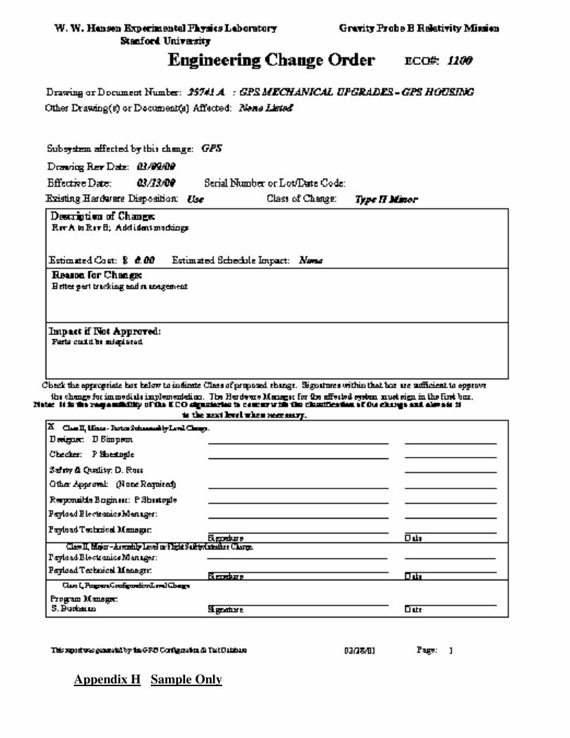
"Engineering Change Order" form, (Appendix G). Each ECO form will have ECO No assigned
by the Documentation Center (sequential order).
Change effectivity
The effectivity point to changed documents (e.g. Date, Serial Number or Lot Number) shall be
defined by the Chairman. The Responsible Engineer shall specify disposition regarding existing
items, whether in process or in stores. The disposition shall be Use-As-Is per the old Revision,
P0098 Rev B Page 21
Rework to the new Revision or Scrap.
Distribution
It is the responsibility of the RE (or his assignee) to distribute the changed drawing to the relevant
persons. This may includes functions as: Manufacturing (in house or vendors),
Receiving Inspection, Bonded Stores, Assembly and/or Testing. The RE (or his assignee) will
also verify eliminating of the old version.
Follow up
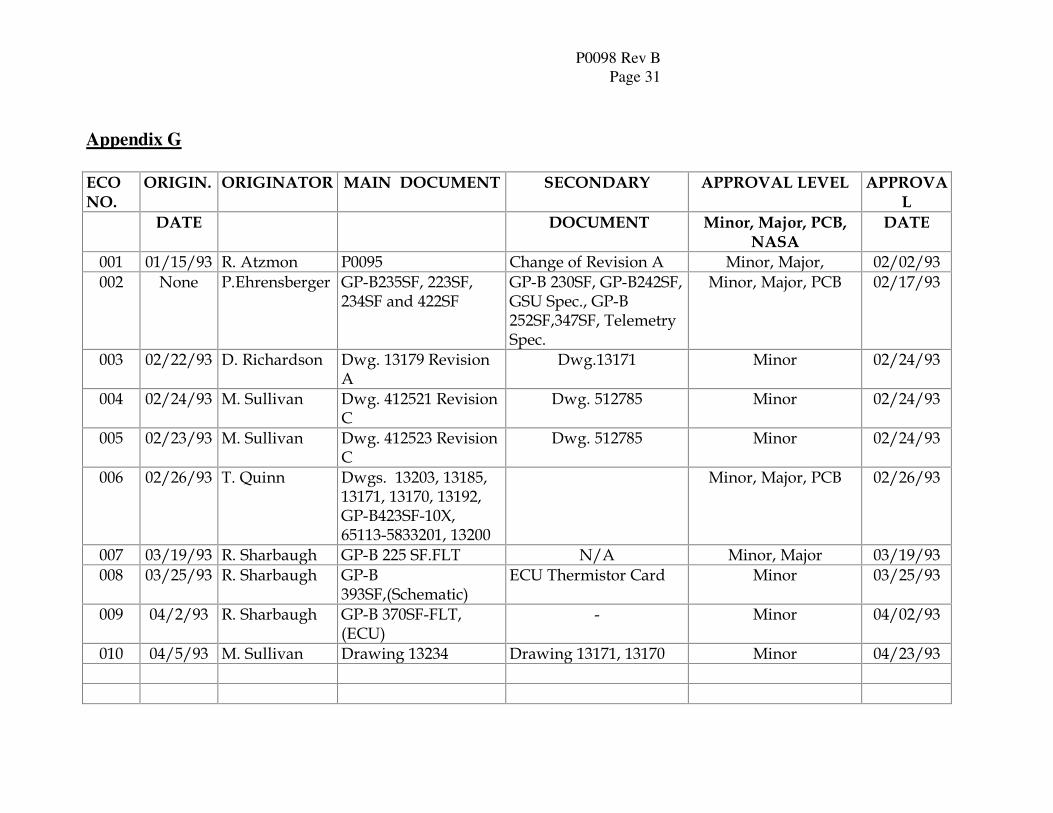
The Documentation Center shall keep an updated ECO Log (Appendix H) for follow up of open
change requests. The log shall assist the System Effectiveness Manager in the verification that
each ECO has been approved and reported as required.
Reports
The Quality Engineer System Effectiveness Manager during each Monthly Review shall report all changes. A copy of the handout of each review shall be sent to MSFC. All Change documentation is open for MSFC review.
5.3.4.4 Type II, Class 2 Minor Changes
For reviewing and approval of Class 2 Minor Changes the Responsible Payload Manager will be
the SU chairperson. Other members will include the Responsible Design Engineer and the System
Effectiveness Manager. The Form to be used is Engineering Change Order (ECO) and is
generated in the GP-B Configuration & Test Database. A hard copy of the ECO will be attached
to the original drawing.
The Document Control Center will keep an ECO Log to verify incorporation of the ECO in a
timely manner. All ECOs are open for MSFC review.
5.3.4.5 Changes at Sub-Contractors
LMMS and selected other sub-contractors might be granted limited change authority. This authority will be defined in the contract. The classification/definition of changes described in paragraph 5.3.1 5.3.2 will apply.
The process
A subcontractor that was granted Change Authority will establish a Level IV Engineering Change
Board, ECB. This board will include as a minimum the Responsible Engineer and the System
Effectiveness Manager.
P0098 Rev B Page 22
Type II Class 1 Changes, after approval by the Subcontractor's ECB, will be forwarded to SU for
approval by the Responsible Payload Manager. Changes that will be found to be SU's Class 1
Changes will be processed as described in paragraph 5.3.3.1 5.3.4.1. Class 2 Changes will be
approved by the Sub-Contractor's ECB. All Class 2 changes will be open to SU's and MSFC's
review.
The internal procedures for implementation of the Configuration Control will be described in the
Sub-Contractor's Configuration Plan that will be approved by SU and MSFC.
Sub-Contractors without Change Authority
Configuration Control for Sub-Contractors without Change Authority will be performed by SU as
described in paragraphs 5.3.3 the SOW.
6. Configuration Management for Product
6.1 Product Identification
Product identification is defined as hardware or software as described below.
6.1.1 Hardware Identification
Each Technical Document (Drawing, Spec etc.) will include the Identification Number of the
article/material. For fabricated parts the ID No is the Drawing Number plus Lot Number which is
the date of fabrication. When Serial Numbers are required, they will be assigned by the RE. For
purchased parts (Off the Shelf), the vendor's ID No and Lot No will be used. The method for
identification, usually Tag and Bag, will also be described in the Technical Document.
6.1.2 Software Identification
Title and Revision will identify each Software Module. This information will be logged and control through the LSEE System for LMMS developed software. SU developed Software Modules will be logged and controlled by SU per P0630, Software Quality Assurance Plan.
6.2 As-Built Configuration
6.2.1 Hardware As-Built Configuration
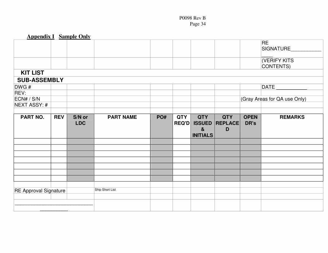
During the manufacturing and assembly of the hardware, the As-Built Configuration will be
recorded using the Kit List forms (Appendix I). These forms will be filled out during each step
of the assembly process. The recorded information includes Part No., Drawing No., Revision,
Title, Quantity and Part Identification- Serial No. or Lot Date Code. (see paragraph 6.1.1)

P0098 Rev B Page 23
The As-Built Configuration will be reported in the Acceptance Data Packages for top assemblies.
The As-Built Configuration will be attached to the back of the Travel Sheet and will be archived.
6.2.2 Software As-Built Configuration
Version Description Document will be generated by the LSEE and will include the Title, and Revision of all the Software Modules that will be used in the Flight SM Units. Su will generate the same documentation for all SU developed software.
7. Audits The program System Effectiveness Manager or his/her designee will perform ongoing audits to verify the performance of this plan.
8. Configuration and Test Database The GP-B Configuration & Test Database, residing on the GP-B server, will include documents and/or information regarding configuration of all the controlled documents. It will be used for reviewing, updating, managing and reporting. The system will include security levels for reading/updating authorities. Users will include SU, LMMS and MSFC. Items included in the database include the following:
8.1 Specifications (SDOC)
Hierarchical list of Specifications and electronic master copy of each specification.
8.2 Program Control Board
Records of all PCBs including the PCB number, originator, title, date, description, reason for change, cost and schedule effect, other documents affected, PCB type, PCB status, and sign-off list.
8.3 Procedures (Pdoc)
Procedure number, title, release/revision date, procedure type, procedure status, sign-off list and electronic master copy of the procedure when possible.
8.4 Science Documents (SDOC)
Science Document number, title, origin date, revision date, sub-system, and author. When applicable this document will show a link to the “Specification Requirements” document as defined in paragraph 5.1.1.
8.5 Drawing
Drawing number, drawing title, release date, revision, revision date, drawing type (part or process), Responsible Engineer, status (released or in-review), sub-system, applicability (GTU-2, Science Mission or both), notes, number of sheets and check box if drawing is expected a
P0098 Rev B Page 24
revision.
8.6 Component
This table includes data of each component described in each drawing. It includes, but is not limited to, details such as material, material specification, magnetic zone. The data relevant to configuration is the revision and revision date which is identical to that shown in the drawing table.
8.7 Drawing Tree
This table includes the links between parts and sub-assemblies. Each part has a Location Number that has a logic link to the parent and its children. The data includes part number, part title, location number, quantity per assembly, total quantity, type-part, assembly or Kit.
8.8 Engineering Change Order (ECO)
This table includes records of all ECOs. It includes the ECO number, drawing or procedure number, drawing or procedure title, revision, revision date, Responsible Engineer, change type, subsystem, description of the change, reason for change, impact if not approved, schedule impact, cost impact, was/is description, existing hardware disposition, sign-off list and status.
8.9 As-Built Configuration
This table includes for each assembly the data of the actual hardware that was used: Assembly number, title and serial number, and for each component the part number, part title, location number (in the drawing tree), revision and serial number or lot date code and quantity.
P0098 Rev B Page 25
Appendix A
Date: 1/01
CO-PRINCIPAL INVESTIGATORS
PROF. DANIEL DEBRA (37)
PROF. BRAD PARKINSON (17)PROF. JOHN TURNEAURE (20)
CO-INVESTIGATORS
DR SASHA BUCHMAN (13)
DR. GEORGE KEISER (23)
DR. BARRY MUHLFELDER (14)
PROF. JIM LOCKHART (21)
RON SINGLEY (1)
PROGRAM TECHNICAL
OPERATIONS
PRINCIPAL INVESTIGATORPROF. FRANCIS EVERITT (39)
PROGRAM MANAGER
DR SASHA BUCHMAN (13)
CHIEF SCIENTIST
DR. GEORGE KEISER (23)
PROGRAM TECHNICAL MANAGER
DR. BARRY MUHLFELDER (14)
CHIEF SYSTEM ENGINEER
BOB SCHULTZ (9)
SYSTEM EFECTIVENESS MANAGER
DORRENE ROSS (3)
SPACE VEHICLE
DEVELOPMENT
HUGH DOUGHERTY (13)
LAUNCH OPERATIONS
GAYLORD GREEN (13)
DEPUTY PROGRAM MANAGER
CONTRACTS &PROCUREMENTTOM LANGENSTEIN (17)
DR. BILL BENCZE (9)
PAYLOAD
ELECTRONICS
ROB BRUMLEY (12)
PAYLOAD TECHNICAL MANAGER
PAYLOAD ELECTRONICS MANAGER
DR. BILL BENCZE (9)
SPACECRAFT
ASSEMBLY
HUGH DOUGHERTY (13)
CRYOGENIC
OPERATIONS
DR. MIKE TABER (15)
SQUID’s
DR. BARRY MUHLFELDER (14)
PAYLOAD
ROB BRUMLEY (12)
SCHEDULES
JIM BURNS (8)
PROGRAM SOFTWARE
AND
MISSION OPERATIONS
COORDINATION
MISSION
OPERATIONS
CENTER
MISSION TIMELINEMISSION SOFTWARE
SCIENCE DATA
ASSOCIATE PROGRAM MANAGERS
PROF. BRAD PARKINSON (17)PROF. JOHN TURNEAURE (20)
MISSION OPERATIONSTOM LANGENSTEIN (17)
MARCIE SMITH (2)
PRINCIPAL INVESTIGATORPROF. FRANCIS EVERITT (39)
P0098 Rev B Page 26
Appendix B Sample Only

P0098 Rev B Page 27
Appendix C
GRAVITY PROBE B
PROCEDURE FOR
SCIENCE MISSION DEWAR
Title
P0xxx Rev. x
Date
Prepared by:
Checked by:
______________________Date_______ ______________________Date_______ Jim Maddocks Tom Welsh Cryogenic Test Cryogenic Test Approvals: ______________________Date_______ Dorrene Ross Quality Assurance ______________________Date_______ ______________________Date_______ Rob Brumley Mike Taber Payload Technical Manager Test Director
SAMPLE ONLY – names may not apply Please note Header w/reference to Pdoc and date require on originals
Please insert page numbers on bottom, center on originals

P0098 Rev B Page 28
Appendix D
W. W. Hansen Experimental Physics Laboratory STANFORD UNIVERSITY
STANFORD, CALIFORNIA 94305-4085
Gravity Probe B Relativity Mission
Title
GP-B Procedure Pxxxx Rev -
DUT PN: xxxxxxx REV
SN:
Date Performed: Prepared by: Scott Smader Date RE, Aft Backplane, Aft Comm Link Approved by: William Bencze Date Payload Electronics Manager. Approved by: Dorrene Ross Date GP-B Quality Assurance
SAMPLE ONLY – names may not apply Please note Header w/reference to Pdoc and date require on originals
Please note Part Number is required, may be shown in the title
Please insert page numbers on bottom, center on originals

P0098 Rev B Page 29
Appendix E
STANFORD GRAVITY PROBE - B
DRAWING APPROVAL
DRAWING TITLE:
DRAWING NUMBER:
DRAWING REVISION: -
REVISION DATE:
NUMBER OF SHEETS:
DRAWING FILE NAME:
APPROVAL ORIGINATION DATE:
X Originator Date
X D. M Ross - Safety, Reliability, and Quality Assurance Date
X B. Bencze – Payload Electronics Manager
SAMPLE ONLY – names and titles may not apply

P0098 Rev B Page 30
Appendix F Sample Only
P0098 Rev B Page 31
Appendix G
ECO
NO.
ORIGIN. ORIGINATOR MAIN DOCUMENT SECONDARY APPROVAL LEVEL APPROVA
L
DATE DOCUMENT Minor, Major, PCB,
NASA
DATE
001 01/15/93 R. Atzmon P0095 Change of Revision A Minor, Major, 02/02/93 002 None P.Ehrensberger GP-B235SF, 223SF,
234SF and 422SF GP-B 230SF, GP-B242SF, GSU Spec., GP-B 252SF,347SF, Telemetry Spec.
Minor, Major, PCB 02/17/93
003 02/22/93 D. Richardson Dwg. 13179 Revision A
Dwg.13171 Minor 02/24/93
004 02/24/93 M. Sullivan Dwg. 412521 Revision C
Dwg. 512785 Minor 02/24/93
005 02/23/93 M. Sullivan Dwg. 412523 Revision C
Dwg. 512785 Minor 02/24/93
006 02/26/93 T. Quinn Dwgs. 13203, 13185, 13171, 13170, 13192, GP-B423SF-10X, 65113-5833201, 13200
Minor, Major, PCB 02/26/93
007 03/19/93 R. Sharbaugh GP-B 225 SF.FLT N/A Minor, Major 03/19/93 008 03/25/93 R. Sharbaugh GP-B
393SF,(Schematic) ECU Thermistor Card Minor 03/25/93
009 04/2/93 R. Sharbaugh GP-B 370SF-FLT, (ECU)
- Minor 04/02/93
010 04/5/93 M. Sullivan Drawing 13234 Drawing 13171, 13170 Minor 04/23/93
P0098 Rev B Page 32
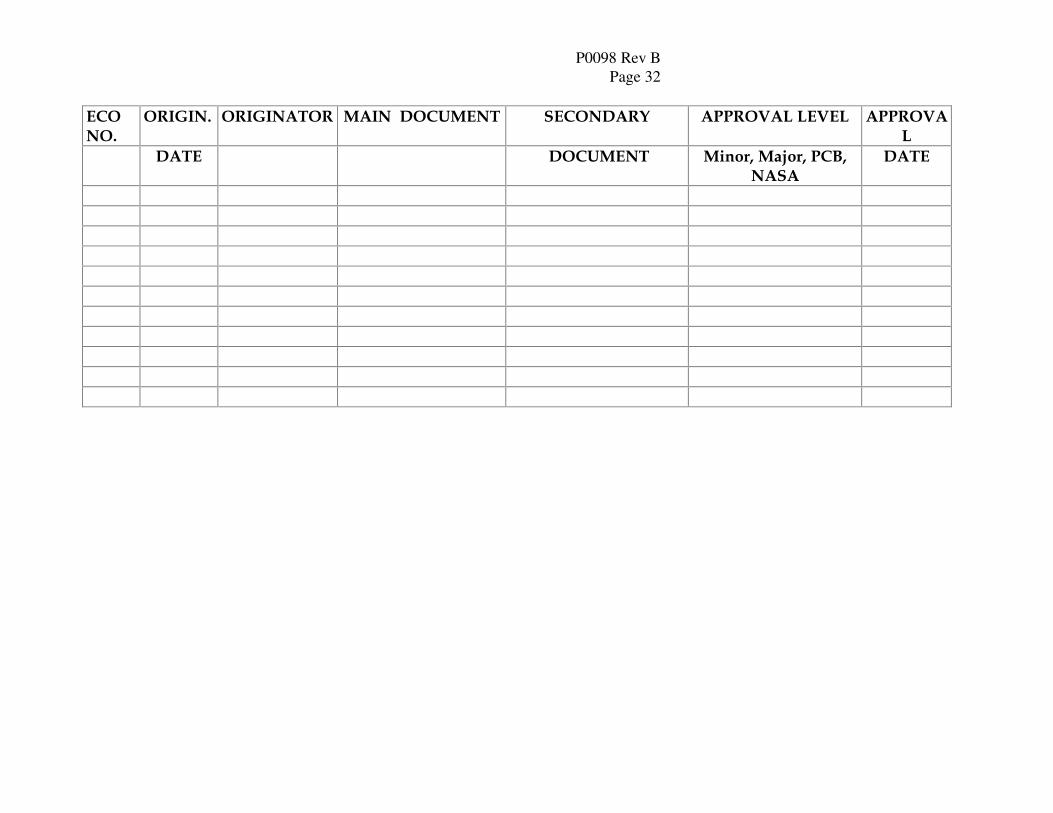
ECO
NO.
ORIGIN. ORIGINATOR MAIN DOCUMENT SECONDARY APPROVAL LEVEL APPROVA
L
DATE DOCUMENT Minor, Major, PCB,
NASA
DATE
P0098 Rev B Page 33
Appendix H Sample Only
P0098 Rev B Page 34
Appendix I Sample Only RE
SIGNATURE_______________
(VERIFY KITS CONTENTS)
KIT LIST
SUB-ASSEMBLY DWG # DATE ___________
REV:
ECN# / S/N (Gray Areas for QA use Only)
NEXT ASSY: #
PART NO. REV S/N or
LDC
PART NAME PO# QTY
REQ'D
QTY
ISSUED
&
INITIALS
QTY
REPLACE
D
OPEN
DR's
REMARKS
RE Approval Signature Ship Short List
______________________________________


![i:J rl]-- srr](https://static.fdocuments.net/doc/165x107/617d56aad7fe5851241b0b1a/ij-rl-srr.jpg)


![SRR and NBCSRR Inspired CPW Fed Triple Band Antenna with ... · property, many researches have been done for the performance improvement of the antenna. SRR ... [16], and each SRR](https://static.fdocuments.net/doc/165x107/5e2b868b3c9fad02ba12180e/srr-and-nbcsrr-inspired-cpw-fed-triple-band-antenna-with-property-many-researches.jpg)