SBC Design Guide - Bircomftp.bircom.com/AudioCodes/SBC-Software-Edition/LTRT-31623 Mediant...SBC...
26
SBC Design Guide May 2014 Document # LTRT-31623 Session Border Controllers Mediant Series AudioCodes
Transcript of SBC Design Guide - Bircomftp.bircom.com/AudioCodes/SBC-Software-Edition/LTRT-31623 Mediant...SBC...

SBC Design Guide
May 2014
Document # LTRT-31623
Session Border Controllers
Mediant Series
AudioCodes

Version 6.8 3 Mediant SBC
SBC Design Guide Contents
Table of Contents 1 Introduction ......................................................................................................... 7
2 Network Architecture .......................................................................................... 9
3 Network Connections ....................................................................................... 11
4 Signaling Elements (SRD and IP Groups) ....................................................... 13
5 Routing ............................................................................................................... 15
6 Interworking and Device Capacity ................................................................... 17
7 Capacity and Quality-of-Service Planning ...................................................... 19
8 Security .............................................................................................................. 21
9 High Availability ................................................................................................ 23

SBC Design Guide 4 Document #: LTRT-31623
Mediant SBC
List of Figures Figure 1: Example of SBC Deployment with LAN-WAN Connections ................................................... 11 Figure 2: Example of SBC Deployment with Multiple IP Groups and SRDs .......................................... 14 Figure 3: Direct Physical Connection of Maintenance Interface ............................................................ 24 Figure 4: Maintenance Interface Connection via External Network Infrastructure ................................. 24

Version 6.8 5 Mediant SBC
SBC Design Guide Notices
Notice This document provides guidelines for planning and designing the deployment of AudioCodes Mediant Session Border Controllers (E-SBC). Information contained in this document is believed to be accurate and reliable at the time of printing. However, due to ongoing product improvements and revisions, AudioCodes cannot guarantee accuracy of printed material after the Date Published nor can it accept responsibility for errors or omissions. Before consulting this document, check the corresponding Release Notes regarding feature preconditions and/or specific support in this release. In cases where there are discrepancies between this document and the Release Notes, the information in the Release Notes supersedes that in this document. Updates to this document and other documents as well as software files can be downloaded by registered customers at http://www.audiocodes.com/downloads.
© Copyright 2014 AudioCodes Ltd. All rights reserved. This document is subject to change without notice.
Date Published: May-28-2014
Trademarks AudioCodes, AC, AudioCoded, Ardito, CTI2, CTI², CTI Squared, HD VoIP, HD VoIP Sounds Better, InTouch, IPmedia, Mediant, MediaPack, NetCoder, Netrake, Nuera, Open Solutions Network, OSN, Stretto, TrunkPack, VMAS, VoicePacketizer, VoIPerfect, VoIPerfectHD, What’s Inside Matters, Your Gateway To VoIP and 3GX are trademarks or registered trademarks of AudioCodes Limited. All other products or trademarks are property of their respective owners. Product specifications are subject to change without notice.
WEEE EU Directive Pursuant to the WEEE EU Directive, electronic and electrical waste must not be disposed of with unsorted waste. Please contact your local recycling authority for disposal of this product.
Customer Support Customer technical support and service are generally provided by AudioCodes’ Distributors, Partners, and Resellers from whom the product was purchased. For technical support for products purchased directly from AudioCodes, or for customers subscribed to AudioCodes Customer Technical Support (ACTS), contact [email protected].
Abbreviations and Terminology Each abbreviation, unless widely used, is spelled out in full when first used. Throughout this manual, unless otherwise specified, the term SBC refers to the AudioCodes SBC products.

SBC Design Guide 6 Document #: LTRT-31623
Mediant SBC
Related Documentation
Manual Name
Mediant 500 E-SBC User's Manual
Mediant 800B Gateway and E-SBC User's Manual
Mediant 1000B Gateway & E-SBC User's Manual
Mediant 3000 SIP User's Manual
Mediant 2600 E-SBC User's Manual
Mediant 2600 E-SBC User's Manual
Mediant 4000 SBC User's Manual
Mediant 9000 SBC User's Manual
Mediant Server & Virtual Editions SBC User’s Manual
Notes and Warnings
Note: The scope of this document does not fully cover security aspects for deploying the device in your environment. Security measures should be done in accordance with your organization’s security policies. For basic security guidelines, you can refer to AudioCodes Recommended Security Guidelines document.
Documentation Feedback AudioCodes continually strives to produce high quality documentation. If you have any comments (suggestions or errors) regarding this document, please fill out the Documentation Feedback form on our Web site at http://www.audiocodes.com/downloads.

Version 6.8 7 Mediant SBC
SBC Design Guide 1. Introduction
1 Introduction This SBC Design Guide document provides important information for ensuring the successful deployment of AudioCodes family of Mediant™ Enterprise Session Border Controllers (hereafter, referred to as SBC). This document provides a detailed analysis of the various aspects and concepts of SBC deployment as well as design recommendations and planning. This document is intended for the person responsible for planning the SBC deployment prior to installation.

SBC Design Guide 8 Document #: LTRT-31623
Mediant SBC
Reader's Notes

Version 6.8 9 Mediant SBC
SBC Design Guide 2. Network Architecture
2 Network Architecture The guidelines discussed in this document relate to a network architecture where the SBC comprises the following two legs: Leg on the LAN - this is the trusted network Leg on the WAN - this is an untrusted network Based on this architecture, the following areas need to be defined: Network connections – see Section 3 on page 11 Signaling elements (SRDs and IP Groups) – see Section 4 on page 13 Call routing – see Section 5 on page 15 Interworking – see Section 6 on page 17 Capacity planning – see Section 7 on page 19 Security – see Section 8 on page 21 High Availability – see Section 9 on page 23

SBC Design Guide 10 Document #: LTRT-31623
Mediant SBC
Reader's Notes
Version 6.8 11 Mediant SBC
SBC Design Guide 3. Network Connections
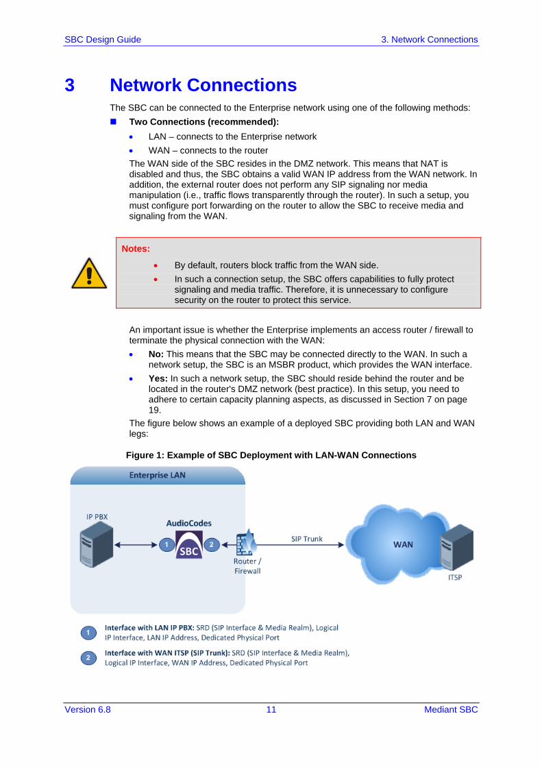
3 Network Connections The SBC can be connected to the Enterprise network using one of the following methods: Two Connections (recommended):
• LAN – connects to the Enterprise network • WAN – connects to the router The WAN side of the SBC resides in the DMZ network. This means that NAT is disabled and thus, the SBC obtains a valid WAN IP address from the WAN network. In addition, the external router does not perform any SIP signaling nor media manipulation (i.e., traffic flows transparently through the router). In such a setup, you must configure port forwarding on the router to allow the SBC to receive media and signaling from the WAN.
Notes:
• By default, routers block traffic from the WAN side. • In such a connection setup, the SBC offers capabilities to fully protect
signaling and media traffic. Therefore, it is unnecessary to configure security on the router to protect this service.
An important issue is whether the Enterprise implements an access router / firewall to terminate the physical connection with the WAN: • No: This means that the SBC may be connected directly to the WAN. In such a
network setup, the SBC is an MSBR product, which provides the WAN interface. • Yes: In such a network setup, the SBC should reside behind the router and be
located in the router's DMZ network (best practice). In this setup, you need to adhere to certain capacity planning aspects, as discussed in Section 7 on page 19.
The figure below shows an example of a deployed SBC providing both LAN and WAN legs:
Figure 1: Example of SBC Deployment with LAN-WAN Connections

SBC Design Guide 12 Document #: LTRT-31623
Mediant SBC
Single Connection to LAN Only: This setup typically means that the SBC handles
most of the signaling interoperability and/or media (RTP) mediation. All network translations and security is done by the external router.
Notes:
• If your environment has additional network entities on the LAN and/or WAN (for example, PBX users or an alternative SIP trunk), it is recommended to configure additional logical interfaces for these entities. For example, if the environment includes a group of users (User-type IP Group), you should create an additional interface for this group in order to prevent interference between it and the other entities. This is very important for security and routing.
• You must determine whether a separated physical and logical interface is required for management.

Version 6.8 13 Mediant SBC
SBC Design Guide 4. Signaling Elements (SRD and IP Groups)
4 Signaling Elements (SRD and IP Groups) Before configuring the SBC, you should familiarize yourself with the main SBC configuration elements and terms: Configuration Elements that Configure the Device Side:
• SRD: The SRD represents a logical VoIP network. Each logical or physical connection requires an SRD. For example, if the SBC interfaces with both the LAN and WAN you would need to configure a different SRD for each one. The SRD is composed of the following : ♦ SIP Interface: The SIP Interface defines a listening port and type (TLS) for
SIP signaling traffic on a specific logical IP network interface of the SBC. ♦ Media Realm: The Media Realm defines a UDP port range for RTP (media)
traffic on a specific logical IP network interface of the SBC. Note that the Media Realm and SIP Interface typically use the same logical network interface. However, you may separate these to use different logical interfaces.
Configuration Elements for the Remote Entity with which SBC Communicates: • IP Group: The IP Group represents a SIP entity on the network with which the
SBC communicates. This can be a server (e.g., IP PBX or ITSP) or it can be a group of users (e.g., LAN IP phones). For servers, the IP Group is typically used to define the server's IP address by associating it with a Proxy Set. A typical deployment consists of multiple IP Groups associated with the same SRD. For example, you can have two LAN IP PBXs on the same SRD and two ITSPs / SIP Trunks on the same SRD (as shown in Figure 2). Once IP Groups have been configured, they are used to configure IP-to-IP routing rules for denoting the source and destination of the call.
• Proxy Set: The Proxy Set defines the destination addresses (IP address or FQDN) of the SIP entity server. Proxy Sets can be used to configure load balancing between multiple servers.
• IP Profile: The IP Profile defines a set of call capabilities relating to signaling (e.g., SIP message terminations such as REFER) and media (e.g., coder used and transcoding method).
• Classification: The Classification process identifies the IP Group from where the call is received, by matching various characteristics of the incoming SIP message. This provides enhanced security by enabling the SBC to accurately identify calls with a specific IP Group while rejecting those that do not match any user-defined characteristics.

SBC Design Guide 14 Document #: LTRT-31623
Mediant SBC
Figure 2 shows an example using the SBC configuration elements discussed above. This example shows a deployment consisting of the following: Two LAN IP PBXs, using the same logical network interface (LAN), physical port, and
SRD. Each IP PBX is configured with an IP Group and different characteristics (IP Profile and Classification rule).
Two SIP trunks (ITSPs), using the same logical network interface (WAN), physical port, and SRD. Each ITSP is configured with an IP Group.
Remote WAN users, using a different SRD, IP Group, and logical network interface than that used for the ITSP, but using the same port.
Figure 2: Example of SBC Deployment with Multiple IP Groups and SRDs

Version 6.8 15 Mediant SBC
SBC Design Guide 5. Routing
5 Routing Each IP entity or IP Group defines the other entities which it is allowed to communicate with, and which it should not communicate with. For example, users may be configured to allow communication with the IP PBX, but not directly with the ITSP. A typical set of configured IP-to-IP routing rules would include the following: Calls from LAN IP PBX to WAN ITSP Calls from WAN ITSP to LAN PBX Calls from LAN PBX 1 to LAN PBX 2 Calls from LAN PBX 2 to LAN PBX 1 Calls from LAN PBX to WAN users Calls from WAN users to LAN PBX When planning the routing requirements, adhere to the following guidelines: 1. List all the customer's routing requirements and scenarios. 2. Determine whether load sharing and/or redundancy on the WAN side (for example,
using two SIP trunks) are needed. 3. Define all possible points of failures (e.g., failure of the IP PBX) and what happens in
failure scenarios with regards to SIP signaling, fault management (traps/notifications), and SIP release cause codes.
4. It is crucial that you configure error handling and alternative routing, for example, for connectivity failures at the WAN ITSP or LAN PBX.
5. Configure how the device identifies that the network entity is "alive". For example, you can use SIP keep alive (OPTIONS), receipt of SIP error codes, or transport layer timeout.
6. For alternative routing, ensure that you are aware of the reason for failure. Differentiate between a PBX that is down to one that is unable to handle calls due to various other reasons such as non-existent users, capacity issues, or even wrong number.

SBC Design Guide 16 Document #: LTRT-31623
Mediant SBC
Reader's Notes

Version 6.8 17 Mediant SBC
SBC Design Guide 6. Interworking and Device Capacity
6 Interworking and Device Capacity For each IP entity, the supported signaling and media capabilities must be defined and interworking requirements between these entities must subsequently be planned. For typical deployments, it is recommended to refer to AudioCodes interoperability documents for explanations on configuration between the LAN environment and the required SIP Trunk(s). This will facilitate deployment and answer many interoperability issues with which the customer is often unaware of. The following critical points should be answered by the customer, which will determine the suitable AudioCodes product, capacity and configuration: 1. Does the deployment require voice coder transcoding and what is the required
capacity? • Be aware that coder transcoding requires two DSP channels. Refer to the DSP
table in the Release Notes to define the maximum capacity per product. • Many SIP Trunks offer two types of coders – G.711 and G.729. The reason for
this is one of the following: ♦ Cost effective - G.729 reduces throughput capacity and slightly reduces the
quality and hence, is often "sold" cheaper. ♦ Eliminates the need for transcoding when G.729 is used in the LAN.
2. Does the deployment include fax and what type of fax transmission is used per entity? • For example, Microsoft® Lync™ enforces fax-over-G.711 only (i.e., in-band),
while most SIP Trunks require T.38 (to achieve better quality). • Fax routing - many deployments include dedicated solutions for fax termination. • Fax capabilities may require DSP resources for detection and transcoding. • Typically, fax capacity attributes to only 5% of the total call capacity. The
customer should define this fax capacity requirement. 3. Does the deployment require tones generation and detection?
In some environments, the SBC (similar to the Gateway) should be able to detect and generate tones toward each entity and on behalf of other entities. For example, in many Lync deployments, the ringback tone from the SIP Trunk to the Lync client is provided by the SBC. Tones detection and generation are handled by the SBC's DSPs, requiring only one DSP channel. As tones are required only at the beginning of the call—before voice established—the assumption is that 10% of total capacity will require DSPs for tones.
4. Does the deployment require DTMF handling? • Typically, DTMF handling requirement will be known from the interoperability
document. • DTMF transcoding requires two DSPs (same as coder transcoding) and affects
the total capacity of the SBC. 5. How many call attempts per second (CAPS) is required?
All AudioCodes SBCs support 100-sec call time (90-sec average hold time, and 10-sec setup time). This 100-sec time is sufficient for most deployments (the average in the industry is usually greater than 300 sec). However, if the customer requires a different capacity, please consult with AudioCodes experts.
SBC Design Guide 18 Document #: LTRT-31623
Mediant SBC
6. Does the deployment require user handling? In deployments where the SBC needs to handle user terminals and clients, the following elements must be defined: a. Define User Capacity: For some solutions, this requires a different license. b. Define Connection and Authentication Method:
♦ For maximum security, it is recommended to use TLS. However, the number of TLS connections is less than the maximum user count supported per SBC device.
♦ The device that is required to authenticate the users must be determined—the SBC itself or the PBX. If the SBC must authenticate the users, be aware of the required "logistics" to define each username/password on the device.
c. Define Registration Refresh Timeout: All AudioCodes SBCs assume a minimum of 300-sec refresh time. If the deployment requires a shorter timeout, the capacity of the SBC may be adversely impacted. Please consult with AudioCodes experts.
d. Define Maximum Non-call Related SIP Messages: Define the maximum number of non-call related messages (i.e., SUBSCRIBE and NOTIFY) expected in the deployment per user device. By default, the SBC can handle SUBCRIBE / NOTIFY sessions up to the number of users defined in the Software License Key. If more than one message per user device is required, please consult with AudioCodes SBC experts regarding capacity and support.
7. Define SRTP Requirements: All AudioCodes SBCs are capable of handling SRTP with any other media or signaling functionality. Be aware that SRTP-to-RTP handling may reduce the total capacity of the SBC.

Version 6.8 19 Mediant SBC
SBC Design Guide 7. Capacity and Quality-of-Service Planning
7 Capacity and Quality-of-Service Planning One of the most crucial factors to consider when building the SBC voice network is proper capacity planning. Within capacity planning, required WAN bandwidth according to the used voice codec must be calculated in order to meet the customer's requirements for maximum number of concurrent call sessions. Capacity planning is vital if the customer's network implements an access router / firewall to terminate the physical connection with the WAN. In this setup, as mentioned previously, the SBC should reside behind the router and be placed in the router's DMZ network (best practice). Adhere to the following recommended capacity planning guidelines: 1. Define the maximum number of concurrent SBC call sessions required by the
customer. 2. Check the capacity of the third-party router concerning the number of packets per
second (PPS) according to the used coder and the router's capabilities. Based on the coder usage, calculate the traffic and confirm the network has correct capacity. The router should handle the appropriate PPS, not only the total data transfer rate (Mbps). For example, using the G.711 coder with 20-ms sample rate, the router should handle each 1,000 calls at least 1,000 × 50 PPS = 50,000 PPS of 256 bytes size (G.711 is 208 bytes). As RTP traffic is bi-directional, this figure needs to be doubled to take into account both directions. In other words, the router capability should handle 100,000 PPS (50,000 * 2). Vendor routers provide PPS per 64, 256, 512, 1280, and 1518 bytes packets.
3. Ensure that the external router is configured to allocate higher priority queuing to voice than data (i.e., Low Latency Queuing / LLQ). Voice is extremely delay-sensitive and must be given preferential treatment over all other traffic. This can be done either by setting QoS based on the VLAN-IP level at the router, which means that QoS need not be configured on the SBC. If QoS is based on 802.1p or DiffServ, the SBC must be configured with the appropriate settings (DiffServ for SIP signaling and media traffic).
A brief explanation on calculating required bandwidth is provided below. The table below shows the coder specifications of two common coders, G.711 and G.729, and uses some of the values as an example in explaining the bandwidth calculation.
Coder Specification Bandwidth Calculation
Coder Bit Rate (Kbps)
Sample Size
(Bytes)
Packetization Time
(ms)
Voice Payload Size Packets Per Second
(PPS)
WAN Bandwidth
(Kbps) Bytes ms
G.711 64 80 10 160 20 50 87.2
G.729 8 10 10 20 20 50 31.2
The terms used in the coder specification include the following: Bit Rate (Kbps): Number of bits per second transmitted for the voice call. Sample Size (Bytes): Number of bytes captured by the DSP at each codec sample
interval (packetization time). Packetization time (ptime): Interval (ms) at which the codec performs each capture or
sample.

SBC Design Guide 20 Document #: LTRT-31623
Mediant SBC
The formula for calculating the coder bit rate is shown below:
Coder bit rate = codec sample size / codec ptime
For example, the G.729 coder operates at ptime of 10 ms with 10 bytes (80 bits) per sample. The bit rate is calculated as follows:
Coder bit rate = 80 (bits) / 0.01 (sec) = 8000 bps = 8 Kbps
To support the voice coder rate, the WAN router must provide sufficient bandwidth. In calculating the bandwidth, the following related terms are used for coder bandwidth: Voice Payload Size (Bytes): Size of the payload in each coder sample. This can be
represented in different formats: • Number of bytes (or bits) that are filled into each packet. The voice payload size
is in multiples of the codec sample size. For example, G.729 packets can use 10, 20, 30, 40, 50, or 60 bytes of voice payload size.
• Coder samples. For example, a G.729 voice payload size of 20 ms (i.e., two 10 ms codec samples) represents a voice payload of 20 bytes: (20 bytes * 8) / (20 ms) = 8 Kbps
Packets per Second (PPS): Number of packets that must be transmitted every second in order to deliver the coder bit rate. For example, for a G.729 call with voice payload size per packet of 20 bytes (160 bits), 50 packets need to be sent every second: PPS = 8 Kbps / 160 bits per packet = 50
The bandwidth calculation includes the following: Total packet size = 20 bytes for IP header + 20 bytes for UDP/RTP header + 18 for
Ethernet header + voice payload size PPS = codec bit rate / voice payload size Bandwidth = total packet size * PPS For example, to calculate the required bandwidth for a G.729 call (8 Kbps codec bit rate) with 20 bytes voice payload: 1. Total packet size (bytes) = 40 (IP/UDP/RTP header) + 20 (voice payload) = 60 bytes =
60 * 8 bits = 480 bits 2. PPS = 8 Kbps (codec bit rate) / 160 bits (default payload size – 20 Bytes * 8) = 50
PPS 3. Bandwidth per call = 480 bits (total voice packet size) * 50 pps = 24 Kbps

Version 6.8 21 Mediant SBC
SBC Design Guide 8. Security
8 Security Security concerns two main areas – protecting the SBC device itself and protecting the VoIP service. These two areas are discussed below: Protecting the Device Itself:
• Management: ♦ Determine the required management interfaces (e.g., Web, EMS, and CLI). ♦ Determine from where management interface is accessed – LAN or WAN. If
the Enterprise will manage the SBC (typical scenario), the management interface is from the LAN side. If it is a managed solution (i.e., done by the service provider), management is done from the WAN side. For securing management from LAN or WAN, refer to the Security Guidelines document.
♦ Enable only management interfaces that are needed and block other interfaces (that may pose a security threat). Note: CLI may be used for debugging even though the customer may not need it for management; blocking this interface may cause future debugging problems.
♦ Restrict users for each management interface by defining users and passwords that can access the SBC (using for example, the Web & Telnet IP Access List or a RADIUS server). It is highly recommended not to use the default management username and password; change it as soon as the SBC is deployed.
♦ It is highly recommended to use secured management, for example, HTTPS, SSH, and SNMPv3 (and not a clear text protocol).
• On the signaling level, use the Layer 3/4 access list (Firewall) and SIP allow-block rules (Layer 5-7 access list using the SIP Message Policy table per SIP Interface). This is especially required on the WAN interface (the network is usually protected on the LAN). For example, you should configure the Layer-3/4 firewall to allow SIP access only from IP addresses of the ITSP, while completely blocking all other IP addresses. This will prevent any type of attack, and the reuse of the IP addresses (i.e., IP spoofing) of the ITSP is not likely to happen since the service provider usually protects itself from anyone else using its IP addresses.
• Define handling of traffic overflow (oversubscription of VoIP calls) on the SBC (using the Admission Control table).
Protecting the Service: • Do not configure a default routing rule that is used if all other routing rules fail.
Configuring such a routing rule creates a security hole that if identified by an attacker may be used to steal calls. The routing rules must be exact and specific – configured with a precise source identity and destination identity.
• Implement encryption (TLS / SRTP) wherever possible to avoid information being exposed and intercepted.
• Implement Classification rules to define exact characteristics of each entity to enhance security. This enables classification not only based on IP addresses, but also on information that is used by the specific service (e.g., defining a SIP user agent name). If possible, encourage the customer to add specific information at the ITSP or PBX end so that this information can be used in the Classification rule to increase security.

SBC Design Guide 22 Document #: LTRT-31623
Mediant SBC
• Implement call and bandwidth admission control (in the Admission Control table) to define precise capacity, especially on the WAN. This is required for quality and security. The idea is to limit each entity with regards to how much capacity / traffic is allowed by the SBC for that entity. In cases where service theft occurs, at least it can be limited due to the configured maximum capacity. This is extremely important when you have a user's IP Group where you can define how many calls per IP Group or per user. Refer to the Security Guidelines for more information.
• If the WAN SIP Trunk resides in a Multiprotocol Label Switching (MPLS) network, security threats on the SBC and services may be diminished due to the nature of MPLS. However, AudioCodes recommends that security be configured on MPLS or public Internet. If the SIP Trunk is not in an MPLS network but on the Internet, security measures must be set to the maximum.
For device and service protection, monitor the security alarms such as CAC threshold, login attempts, and invalid access to the device.
Note: For detailed information on implementing security on the SBC, refer to the Recommended Security Guidelines document.

Version 6.8 23 Mediant SBC
SBC Design Guide 9. High Availability
9 High Availability The SBC's High Availability (HA) concerns two redundancy aspects: Network redundancy (relevant for all SBC products): This is achieved by
employing dual Ethernet ports for each logical network interface. Therefore, each physical Ethernet port making up the port pair must be connected to separate external switches to achieve maximum network redundancy and availability. This configuration is supported on all AudioCodes SBC devices1. At any given time, only one of these physical Ethernet ports carries traffic. The standby port is up in Layer 2, but does not carry traffic (i.e., there is no MAC address or IP address on this interface). This is designed to avoid any type of spanning tree protocol (STP) or loops. Therefore, to improve fast resiliency, it is recommended to disable STP on the external switches connected to AudioCodes SBC. If STP is not disabled, switchover between switches may cause delay in traffic for a few seconds (depending on switch vendor).
Note: The Ethernet-port pair feature is currently not available on the MSBR series. When deploying MSBR devices, other techniques exist to achieve network redundancy. For more information, refer to the User's Manual.
Product-level redundancy: These products provide the capability for deploying two
standalone units, sharing identical configuration and call processing, while only one of them is alive at any given time. Both units must be connected to the network in the same physical manner, i.e., same Ethernet ports and settings and same logical network interfaces. In such a setup, the network should enable each unit to use the same logical interfaces at any given time. There is no issue with loops as each unit has its own MAC address and when the units are synchronized with one another, only one of them uses the shared interfaces.
Note: Product-level redundancy is applicable only to the following products: Mediant 500 E-SBC, Mediant 800B Gateway & E-SBC, Mediant 2600 E-SBC, Mediant 4000 SBC, Mediant 9000 SBC, and Mediant Software SBC.
The product-level redundancy can be deployed in one of the following modes: • Back-to-Back Connection: This is the preferred mode. In this mode, the
Maintenance interface is physically connected directly between the two units. ♦ Advantage: This is a more reliable mode as less intermediary network
components are located between the units that can cause connectivity failure (i.e., no point-of-failure from network elements).
♦ Limitation: This mode may be problematic if the two units are located in different geographical areas that do not have direct physical connection.
1 LAN ports on MSBR devices (even when used for SBC functionality) do not behave like this, but act as a LAN switch.

SBC Design Guide 24 Document #: LTRT-31623
Mediant SBC
Figure 3: Direct Physical Connection of Maintenance Interface
• Connection via External Network Infrastructure: In this mode, the
Maintenance interface is connected through external switches / routers located between the two units. In such a mode, AudioCodes requires that the network be fully resilient between the units to avoid scenarios where both units are alive but cannot communicate with one another (i.e., Active-Active state), for example, if in Figure 4 the unit at Site A has no connectivity with the unit at Site B. These sites must always be in communication. If not, the redundant unit will also become active, resulting in call processing problems and functionality. In this mode, where the units are connected to different switches and routers in different geographical locations (i.e., each at its site), the network is still required to be fully synchronized (for example, by using Virtual Router Redundancy Protocol / VRRP) to enable the units to use the shared logical interfaces upon failure of one of the units. If site redundancy is implemented, AudioCodes requires that the communication link between the two units be less than 50 ms in terms of delay.
Figure 4: Maintenance Interface Connection via External Network Infrastructure
The Maintenance interface provides the following functions: • Sending of keep-alive packets to verify connectivity between the units. • Synchronizing all configuration as well as call processing status between the
units. • Synchronizing "health" status of units, for example, failure of physical interface,
DSP failure, software exceptions. • Regarding management: All actions on the active unit are automatically replicated
on the redundant unit. In other words, the two units have only one logical management interface shared between them. If a problem occurs in one of the units, it is possible to retrieve information from the redundant (problematic) unit via the active unit by using the Maintenance interface. For example, if a switchover occurs due to a software crash in one of the units, it is possible to access the "crashed" unit, by doing a telnet to the active unit using the Maintenance interface address and then accessing the "crashed" unit using its maintenance interface.
Version 6.8 25 Mediant SBC
SBC Design Guide 9. High Availability
• HA also enables software upgrade without affecting traffic. The upgrade is done in serial manner, whereby when one is being upgraded the other runs the traffic (Hitless Upgrade).
Note: For a full description of HA, refer to the User's Manual.
When deploying the HA units in different geographical locations, you must consider the following factors (in addition to network resiliency): Latency between sites must be less than 50-ms delay between units on the
Maintenance interface. Verify that the carrier side can pass the traffic between the units using the same
shared logical network interfaces, which are exposed to the WAN / carrier network. Typically, carriers allocate IP addresses on the WAN per geographical location and thus, units in different geographical areas are not allocated the same IP addresses. Therefore, it is recommended that both units are serviced (connected) by the same carrier (however, as mentioned, the same carrier may not be able to service the two sides with the same IP addresses if in different geographical locations).
Note: Where the network design cannot meet these requirements, a different solution must be designed whereby the two units are implemented in a load-sharing mode (without HA), or where HA is implemented at each of the sites.
SBC Design Guide
www.audiocodes.com