Savio Chau Five Classic Components of a Computer Current Topic: Input and Output Control Datapath...
105
Savio Chau Five Classic Components of a Computer • Current Topic: Input and Output Control Datapath Memory Processor Input Output Control Datapath Memory Processor Input Output Network Peripheral Devices
-
date post
21-Dec-2015 -
Category
Documents
-
view
263 -
download
0
Transcript of Savio Chau Five Classic Components of a Computer Current Topic: Input and Output Control Datapath...

Savio Chau
Five Classic Components of a Computer
• Current Topic: Input and Output
Control
Datapath
Memory
Processor
Input
Output
Control
Datapath
Memory
Processor
Input
Output
Network
Peripheral Devices

Savio Chau
What You Will Learn in This Set of Lectures
• I/O System Overview
• I/O System Design Considerations
• I/O System Design Parameters– Connectivtiy – Protocol– Access Control– Performance– Expandability– Failure Handling– Operating System Support
• I/O Implementation Example

Savio Chau
Who Cares About I/O?
• CPU Performance: 60% per year
• I/O system performance limited by mechanical delays (disk I/O)< 10% per year (IO per sec or MB per sec)
• Amdahl's Law: system speed-up limited by the slowest part!10% IO & 10x CPU 5x Performance (lose 50%)10% IO & 100x CPU 10x Performance (lose 90%)
• I/O bottleneck: Diminishing fraction of time in CPUDiminishing value of faster CPUs

Savio Chau
I/O System Architecture Overview
User Application
Operating System
Device Driver
I/O Controller
I/O Device
I/O Device
system call
Memory or I/O Bus
Media
Software
Hardware
Device Driver
Protocol can be defined at
all levels
I/O Controller
Physical
Logical
System Interface

Savio Chau
PC
IF/I
D R
egis
ter
ID/E
X R
egis
ter
EX
/Mem
Re
gis
ter
Mem
/Wr
Re
gis
ter
RFile
Exec Unit
Ra
Rb
Rw Di
Imm16
BusABusB
1
0
0
1
A
PC+4Imm16
BranchTarget
Address
Rs
Rt
Rt
RdI01
Zero
How is the I/O System Related to Processor
Co
ntr
ol
Sig
na
ls
Co
ntr
ol
Sig
na
ls
Co
ntr
ol
Sig
na
ls
PC+4
ExtOpALUSrcALUOpRegDstMemWrBranchMemtoRegRegWrM
ain
Co
ntr
ol
Memory Hierarchy
RAWA
Di
Do
4
I/O Controller
I/O Device
Ad
der
Wr
Savio Chau
A Classificaiton of I/O According to the Targets of I/O Operation
• Processor to MemoryVery low latency, very high throughput, very low protocol overhead
• Processor to PeripheralLatency, throughput, and protocol overhead vary according to the I/O devices
• Processor to Processors
– Tightly Coupled: all processors share a physical memoryLow latency, high throughput, low overhead protocol, coherence problem
– Loosely Coupled: each processor has its own physical memoryMedium latency, medium throughput, high protocol overhead, scalable
• Processor to NetworkHigh latency, low throughput, high protocol overhead, very scalable

Savio Chau
I/O System Example
Processor
Cache
Memory - I/O Bus
MainMemory
I/O Controller
Graphics
Network
DiskDisk
I/O Controller Network Interface
Controller
IEEE 1394 Bus Interface
Contorller
Processor
Cache
To Other Processors or Peripherals on the
IEEE 1394 Bus
Savio Chau
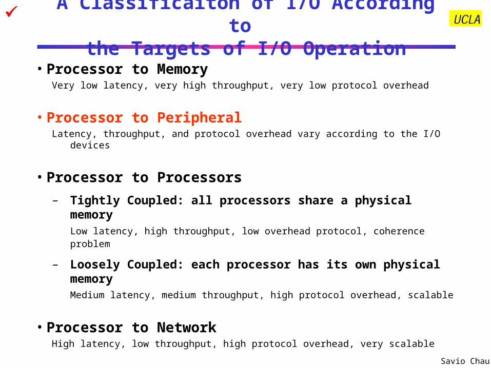
I/O Devices Examples
Device Behavior Partner Data Rate (KB/sec)
Keyboard Input Human 0.01
Mouse Input Human 0.02
Line Printer Output Human 1.00
Floppy disk Storage Machine 50.00
Laser Printer Output Human 100.00
Optical Disk Storage Machine 500.00
Magnetic Disk Storage Machine 5,000.00
Network-LAN Input/Output Machine 20 – 1,000.00
Graphics Display Output Human 30,000.00
• See Backup Slides for More Detailed Information about Some of the I/O Devices

Savio Chau
I/O System Design Process• Establish Requirements: Understanding What You Need
• Select the I/O System That Has the Required Capability: Understand What the I/O System being Considered Can Do
• Integration: Understand How Everything Fits Together
• Implementation
Device A? Device B?
Device B? Device C? Device D?
Bus A?
Bus B?Bus C?
Device A Device B
Device B Device C Device D
Bus B? ?
? ? ?

Savio Chau
I/O System Design Example: Establish Requirements
• Design an I/O architecture for a spacecraft that has the following equipment
Flight Computer
(CDH)
Flight Computer
(ACS)
Flight Computer (Payload)
Star TrackerStar TrackerTelecom Subsystem
Telecom Subsystem
Inertia Measurement Unit
Inertia Measurement Unit
Power Control Unit
Power Control Unit
Thruster Control Unit
Thruster Control Unit
Wide Angle Camera
High Resolution Camera
Radar Sounder
Altimeter
Data Rate: 5 Kbps1transaction/secLatency < 10 ms
Data Rate: 8 Mbps1000 samples/secLatency < 0.1 ms
Data Rate: 10 Kbps1000 samples/secLatency < 0.1 ms
Data Rate: 400 bps2 commands/secLatency < 0.5 sec
Data Rate < 100 bps10 commands/secLatency < 0.1 ms
Data Rate: 20 Mbps2 frames/secLatency < 0.5 sec
Data Rate: 20 Mbps2 frames/secLatency < 0.5 sec
Data Rate: 1 Mbps1 transaction/secLatency < 1 sec
Data Rate: 5 Kbps100 samples/secLatency < 0.01 sec
I/O?
System Constraints (Prioritized):1. Total power consumption of the avionics system < 100 W. 2. The I/O system power consumption should be less than 35% of the avionics system.3. Each subsystem has to meet the latency and throughput requirements4. System reliability should exceed 12 years (i.e., requires fault tolerance)5. The system design should be scalable and distributed.6. Maximum distance between subsystems is 5 meters. Average distance is 3 m.7. Minimize the cable mass.
Savio Chau
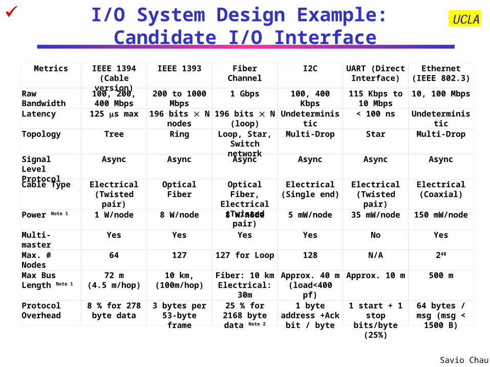
I/O System Design Example: Candidate I/O Interface
Metrics IEEE 1394(Cable version)
IEEE 1393 Fiber Channel I2C UART (Direct Interface)
Ethernet(IEEE 802.3)
Raw Bandwidth 100, 200, 400 Mbps
200 to 1000 Mbps 1 Gbps 100, 400 Kbps 115 Kbps to 10 Mbps
10, 100 Mbps
Latency 125 s max 196 bits N nodes
196 bits N (loop)
Undeterministic < 100 ns Undeterministic
Topology Tree Ring Loop, Star, Switch network
Multi-Drop Star Multi-Drop
Signal Level Protocol
Async Async Async Async Async Async
Cable Type Electrical (Twisted pair)
Optical Fiber Optical Fiber, Electrical
(Twisted pair)
Electrical(Single end)
Electrical(Twisted pair)
Electrical(Coaxial)
Power Note 1 1 W/node 8 W/node 8 W/node 5 mW/node 35 mW/node 150 mW/node
Multi-master Yes Yes Yes Yes No Yes
Max. # Nodes 64 127 127 for Loop 128 N/A 248
Max Bus Length Note 1
72 m(4.5 m/hop)
10 km,(100m/hop)
Fiber: 10 kmElectrical: 30m
Approx. 40 m (load<400 pf)
Approx. 10 m 500 m
Protocol Overhead
8 % for 278 byte data
3 bytes per 53-byte frame
25 % for 2168 byte data Note 2
1 byte address +Ack bit / byte
1 start + 1 stop bits/byte (25%)
64 bytes / msg (msg < 1500 B)
Savio Chau
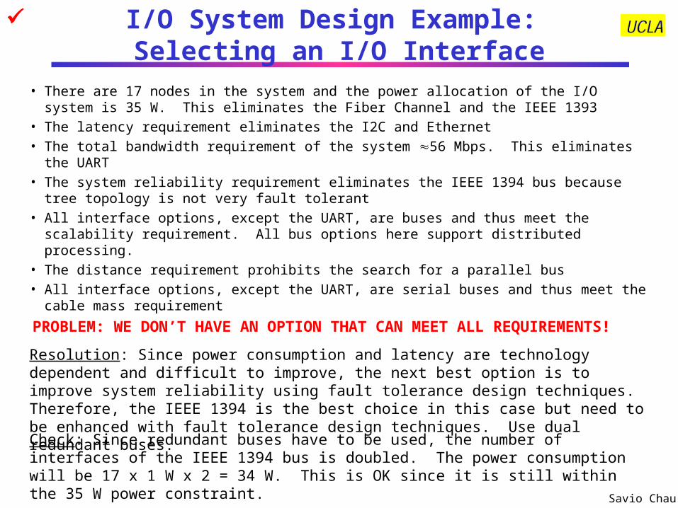
I/O System Design Example: Selecting an I/O Interface
• There are 17 nodes in the system and the power allocation of the I/O system is 35 W. This eliminates the Fiber Channel and the IEEE 1393
• The latency requirement eliminates the I2C and Ethernet• The total bandwidth requirement of the system 56 Mbps. This eliminates the UART• The system reliability requirement eliminates the IEEE 1394 bus because tree topology is
not very fault tolerant• All interface options, except the UART, are buses and thus meet the scalability
requirement. All bus options here support distributed processing.• The distance requirement prohibits the search for a parallel bus• All interface options, except the UART, are serial buses and thus meet the cable mass
requirement
PROBLEM: WE DON’T HAVE AN OPTION THAT CAN MEET ALL REQUIREMENTS!
Resolution: Since power consumption and latency are technology dependent and difficult to improve, the next best option is to improve system reliability using fault tolerance design techniques. Therefore, the IEEE 1394 is the best choice in this case but need to be enhanced with fault tolerance design techniques. Use dual redundant buses.
Check: Since redundant buses have to be used, the number of interfaces of the IEEE 1394 bus is doubled. The power consumption will be 17 x 1 W x 2 = 34 W. This is OK since it is still within the 35 W power constraint.
Savio Chau
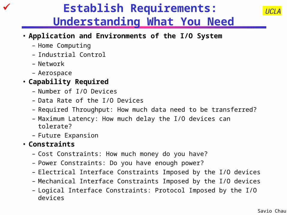
Establish Requirements: Understanding What You Need
• Application and Environments of the I/O System– Home Computing
– Industrial Control
– Network
– Aerospace• Capability Required
– Number of I/O Devices
– Data Rate of the I/O Devices
– Required Throughput: How much data need to be transferred?
– Maximum Latency: How much delay the I/O devices can tolerate?
– Future Expansion• Constraints
– Cost Constraints: How much money do you have?
– Power Constraints: Do you have enough power?
– Electrical Interface Constraints Imposed by the I/O devices
– Mechanical Interface Constraints Imposed by the I/O devices
– Logical Interface Constraints: Protocol Imposed by the I/O devices

Savio Chau
Select I/O System with Required Capability: Understand the I/O System Being Considered
• Performance: How much data can be handled by I/O system being considered– Throughput: function of Bit Rate, Bus Width, Block Size, Protocol Overhead
– Latency or Response Time
– Impact on Processor Performance
• Expandability: How many devices can it handle– Bus Length: Parallel Buses Are Shorter, Serial Buses Are Longer
– Drive Capability: Bus Loading, Transmission Line Effect
– Multi-Level Buses: Bridge Between Buses
• Access Control: How to arbitrate I/O requests among nodes– Master-Slave: One Master Controls All Transactions
• Passive Slaves, Active Slaves (interrupt)
– Multi-Master: Arbitration Required Among Masters (processors, controllers)
• Failure Handling: What the I/O system can do in case of failures?– Reliability vs. Availability
– Fault Tolerant: Fault Detection, Fault Isolation, Fault Recovery

Savio Chau
Integration: Understand How Everything Fits Together
• Physical Interface with the I/O Devices– Electrical Interface
– Mechanical Interface
• Topology – Star, Multi-Drop, Ring, Tree, etc.
• Protocol: Rules of Communication with the I/O Devices– Signal Level Protocol
• Synchronization: Synchronous (Clocked), Asynchronous (handshake)
– Packet / Message Level Protocol
– Addressing Capability: Directed, Broadcast, Multi-Cast
– Transaction Types: Split, Unified
• Operating System Support– Software Device Driver
– Method of Addressing the Devices: I/O Address, Memory Mapped I/O:
– Processor & I/O Devices Interaction: Interrupt, Polling, DMA, I/O Processor
– Resource Management: Sharing of I/O Devices
– Protection: Ensure No Conflicts among I/O Devices

Savio Chau
Implementation
• If Your I/O System Requirement Can be Met by Standard Interfaces– It is easy! Just purchase commercial off-the-shelf (COTS)
components, software, and test equipment and then integrate them
• If Your I/O System Requirement Needs Custom Design, You Have to– Specify the protocol and timing of the signals at the
interface– Design the logic required to implement the specification– Realize the logic design in hardware– Write the software driver to drive the hardware

Savio Chau
Key I/O Design Parameters to be Discussed
• Connectivity
• Protocol
• Access Control
• Performance
• Expandability
• Failure Handling
• Operating System Support
Physical • Protocol• Connectivity• Access Control• Performance• Expandability• Failure Handling
Logical• Protocol• Failure Handling
System Interface• Operating System Support• Failure Handling
Typical I/O System Layers and Key Parameters

Savio Chau
Connectivity

Savio Chau
Connecting I/O to Processor: Direct Interface
• Ad Hoc– No definite number of signals, protocol, electrical interface etc.
• Standards– RS232: Serial interface. Signals include Request-to-Send, Clear-
to-Send, TxData, RxData
– UART (Universal Asynchronous Receiver Transmitter): Serial interface protocol, usually used with the RS232
– IEEE 1284: Parallel interface, commonly used for printer port on PCs
Control
Datapath
Memory
Processor Input
Output
Input
Output

Savio Chau
Connecting I/O to Processor: Buses
• A Bus is – shared communication link
– single set of wires used to connect multiple subsystems
• Bus is also a fundamental tool for composing large, complex systems– systematic means of abstraction
Control
Datapath
Memory
Processor
Input
Output
Input
Output

Savio Chau
Types of Buses• Processor-Memory Bus (design specific)
– Used for Process-to-Memory I/O– Usually is parallel, short, high speed and on the processor broad– Match the processor and memory interfaces to maximize bandwidth– Optimized for cache block transfers
• I/O Bus (industry standard)– Used for Process-to-Peripheral, loosely coupled Processor-to-Processor, and
Processor-to-Network I/Os – Usually is serial, lengthy, slower, and implemented by cables but flexible– Need to match a wide range of I/O devices– Connects to the processor-memory bus or backplane bus through bridges
• Backplane Bus (standard or proprietary)– Used for Process-to-Peripheral, tightly coupled Processor-to-Processor I/Os,
and Processor-to-Network I/Os– Backplane: an interconnection structure within the chassis– Allow processors, memory, and I/O devices to coexist– Usually is parallel, speed is between Processor and I/O Bus– Cost advantage: one bus for all components
• See Backup Slides for Bus Surveys

Savio Chau
A Computer System with One Bus: Backplane Bus
• A single bus (the backplane bus) is used for:– Processor to memory communication
– Communication between I/O devices and memory
• Advantages: Simple and low cost• Disadvantages: slow and the bus can become a major
bottleneck• Example: IBM PC - AT
Savio Chau
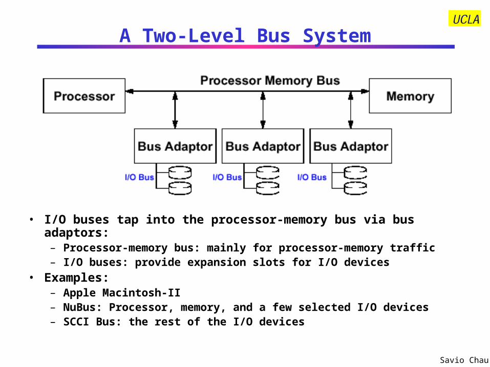
A Two-Level Bus System
• I/O buses tap into the processor-memory bus via bus adaptors:– Processor-memory bus: mainly for processor-memory traffic– I/O buses: provide expansion slots for I/O devices
• Examples: – Apple Macintosh-II– NuBus: Processor, memory, and a few selected I/O devices– SCCI Bus: the rest of the I/O devices

Savio Chau
A Three-Level Bus System
• A small number of backplane buses tap into the processor-memory bus– Processor-memory bus is used for processor memory traffic
– I/O buses are connected to the backplane bus
• Advantage: loading on the processor bus is greatly reduced• Example: See PCI Bus Example

Savio Chau
The General Organization of a Bus
• Data Lines Carry Information Between the Source and the Destination:– Data and Addresses
– Complex Commands
• Control Lines:– Signal Requests and Acknowledgments
Data Lines
Control Lines

Savio Chau
Typical Bus Operation and Interface Control
• I/O Operation Consists of– Check if Device is Available (e.g., check busy signal)
– Send Operation Parameters (e.g., send read/write signals, address)
– Data Transfer (e.g., read or write to Data, Control, Status registers)
– Termination (e.g., send or receive acknowledge signal)
• Methods are:– Programmed I/O
– Interrupt- Driven
– Direct Memory Access (DMA)

Savio Chau
How to Specify a BusParameter Consideration Data Bus Width
Wider bus has higher performance but higher cost
Address Bus Width
Wider bus has larger address space but higher cost
Block size Smaller block has higher percent overhead but lower latency Larger block has lower percent overhead but higher latency.
Topology Multi-drop topology is simpler but not very scalable. Point-to-point topology is more scalable but more complicate.
Access Control
Single master is simpler. Multiple masters is more complicate (requires arbitration) but supports distributed processing
Protocol Synchronous bus is simpler but timing is tighter. Asynchronous bus has more relax timing but more complicate
Transaction Type
Unified transaction is simpler but has lower throughput. Pipelined transaction has higher throughput but is more complicate.

Savio Chau
Examples of Bus Topologies• Multi-Drop Bus
– One media is shared by many devices– If the media is a cable, each device needs a coupler to “tap” into the bus– Need to consider short protection, electrical isolation, and termination
Device 1 Device NDevice 2
Data
Command / Address
Short protection resistors
Bus couplers
Termination Resistors
Isolation (transformer, Optical etc.)
• Point-to-Point Buses– One media between each pair of devices– Many topologies are possible (e.g., ring, tree, star etc.)– Short protection, electrical isolation, and termination are less critical
Device Device
Device
Device Device
Device Device
Device
Device
Device
Device Device
Device
Device
Ring (e.g. Token Ring) Tree (e.g. IEEE 1394) Star (e.g. Fiber Channel)
Savio Chau
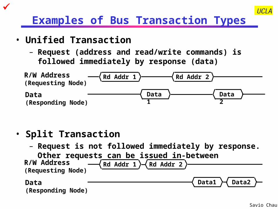
Examples of Bus Transaction Types
• Unified Transaction– Request (address and read/write commands) is followed
immediately by response (data)
• Split Transaction– Request is not followed immediately by response. Other
requests can be issued in-between
Rd Addr 1R/W Address(Requesting Node)
Data1Data(Responding Node)
Data1Data(Responding Node)
Data2
Rd Addr 1R/W Address(Requesting Node)
Rd Addr 2
Rd Addr 2
Data2

Savio Chau
Examples of Bus Protocols
• Synchronous Bus:– Includes a clock in the control lines– A fixed protocol for communication that is relative to the clock– Advantage: involves very little logic and can run very fast– Disadvantages:
• Every device on the bus must run at the same clock rate
• To avoid clock skew, they cannot be long if they are fast
• Asynchronous Bus:– It is not clocked– It can accommodate a wide range of devices (fast and slow)– It can be lengthened without worrying about clock skew– It requires a handshaking protocol which can significantly
reduce the effactive bandwidth
• Some more details in the Protocol discussion

Savio Chau
Backplane Bus Example: PCI Cache
Memory More details in the Protocol discussion

Savio Chau
Key Features of PCI Bus
• 32-bit or 64-bit bus running at 33 MHz or 66 MHz, synchronized to host processor clock
• Block oriented data transfer• Reconfigure bus nodes upon system startup or configuration
changes (Plug-and-Play)• Multi-master, but only one master has bus arbitration capability• Sub-buses include
– Address and Data Bus (Multiplexed)
– Command and Byte Enable Bus
– Interface Control Signals
– Arbitration Signals
– Error Signals
• Reflected wave signal switching• Device select and negative acknowlegment
• More details in the Protocol discussion

Savio Chau
Serial Bus Example: IEEE 1394 (Firewire)
I/O I/O I/O
CPU memory I/O CPU
Any Backplane Bus
IEEE 1394 Bus (backplane environment) bridge
CPU memory I/O CPU
Any Backplane Bus
IEEE 1394 Bus (backplane environment) bridge
IEEE 1394 Bus (Cable environment)
nodes
ports
nodes
Note: IEEE 1394 Bus is a serial bus in both backplane and cable environments
More details in the Protocol discussion

Savio Chau
Key Features of the IEEE 1394 Bus• A digital interface – there is no need to convert digital data into analog
and tolerate a loss of data integrity
• Physically small - the thin serial cable can replace larger and more expensive interfaces
• Adopts a tree topology in cable environment and multi-drop topology in backplane enviroment
• Easy to use - no need for terminators, device IDs, or elaborate setup
• Hot pluggable - users can add or remove 1394 devices with the bus active
• Inexpensive - priced for consumer products
• Scalable architecture - may mix 100, 200, and 400 Mbps devices on a bus
• Flexible topology - support of daisy chaining and branching for true peer-to-peer communication
• Fast - even multimedia data can be guaranteed its bandwidth for just-in-time delivery
• Non-proprietary
• Mixed asynchronous and isochornous traffic
• More details in the Protocol discussion
Savio Chau
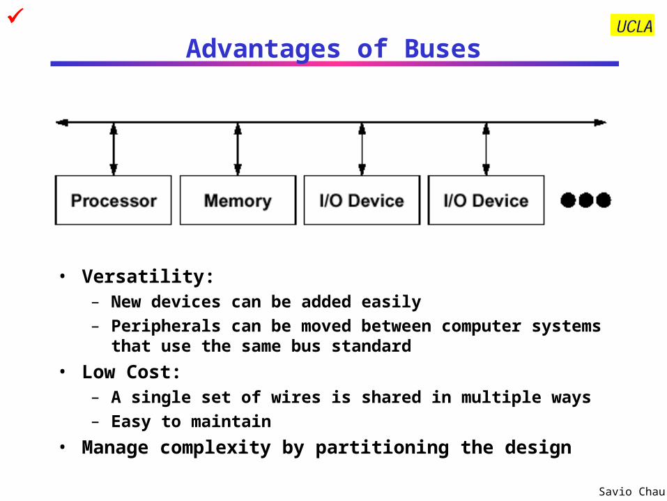
Advantages of Buses
• Versatility:– New devices can be added easily
– Peripherals can be moved between computer systems that use the same bus standard
• Low Cost:– A single set of wires is shared in multiple ways
– Easy to maintain
• Manage complexity by partitioning the design

Savio Chau
Disadvantage of Buses
• It creates a communication bottleneck– The bandwidth of that bus can limit the maximum I/O throughput
• The maximum bus speed is largely limited by:– The length of the bus
– The number of devices on the bus
– The need to support a range of devices with:• Widely varying latencies • Widely varying data transfer rates
• A single point of failure: one bus failure (e.g., short to ground) can fail the entire system

Savio Chau
Protocol: the Rules of Communication

Savio Chau
Signal Level Protocol:Typical Synchronous Protocol
• Wait signal is optional: Slave can use this signal to indicate when it is prepared for data transfer
• Actual transfer goes at bus rate
Valid(master)
Cmd+AddrR/WAddress(master)
Data1 Data1Data(master/slave)
Wait(slave)
Data2
Clock(master)

Savio Chau
Signal Level Protocol: Typical Asynchronous Protocol (Handshaking)
• t0 : Master has obtained control and asserts address, direction, data Waits a specified amount of time for slaves to decode target
• t1: Master asserts request line
• t2: Slave asserts ack, indicating data received
• t3: Master releases req
• t4: Slave releases ack
Address
Data
Rd / Wr(Master)
Req(Master)
Ack(Slave)
Master Asserts Address
Master Asserts Data
Next Address
Write Transaction
t0 t1 t2 t3 t4 t5
Savio Chau
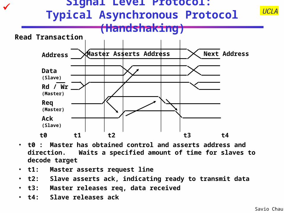
Signal Level Protocol: Typical Asynchronous Protocol (Handshaking)
• t0 : Master has obtained control and asserts address and direction.Waits a specified amount of time for slaves to decode target
• t1: Master asserts request line• t2: Slave asserts ack, indicating ready to transmit data• t3: Master releases req, data received• t4: Slave releases ack
Address
Data(Slave)
Rd / Wr(Master)
Req(Master)
Ack(Slave)
Master Asserts Address Next Address
t0 t1 t2 t3 t4
Read Transaction

Savio Chau
Asynchronous Protocol for Multiplexed Bus
• Three Control Lines– ReadReq: Indicates a Read Request for Memory
• Address is Put on the Data Lines at the Same Time
– DataRdy: Indicates the Data Word is Now Ready on the Data Lines• Data is put on the Data Lines at the Same Time
– Ack: Acknowledge the ReadReq or the DataRdy of the Other Party
(master)
(slave/master)
(slave)
(master/slave)
(slave) (master)
(master) (slave)
Read Example

Savio Chau
State Diagram for Asynchronous Multiplexed Bus
I/O Devices (master)
PutAddress ondata lines;
AssertReadReq
Ack
Ack
2Release data
lines; deassertReadReq
DataRdy
Dat
aRd
y
5Read memory
data fromdata linesassert Ack
DataRdy
Dat
aRd
y
7Deassert
Ack
Idle
ReadReq
Memory (slave)
Rea
dR
eq
1Record
address ondata lines and
assert Ack
ReadReqR
ead
Req
3,4Drop Ack; putmemory dataon data lines;
assertDataRdy
Ack
Ack
6Release data
lines andDataRdy
Address Phase Done
Data Phase Done

Savio Chau
Example of Signal Level Protocol:PCI Bus Protocol (Read)
AddrData
1Data
3Data
2
BusCmd
ByteEnable
ByteEnable
ByteEnable
Target begins to drive data back to initiator Initiator deasserts FRAME#
indicating that it is ready to complete last data phase
Initiator deasserts IRDY#, returning bus to idle state
Wait States
Data Transfers
Target deassertsTRDY# and DEVSEL#
Initiator starts transaction by asserting FRAME#, driviing
address onto AD bus and command onto C/BE bus
Target latch and decode address
and command
Turn-Around cycle. Initiator stops driving AD bus
Initiator stops drivint command and startsdriving byte enables
Target keeps TRDY# deasserted to enforce
turn-around cycle
Target deviceasserts DEVSEL#
CLK
FRAME#
AD
C/BE#
IRDY#
TRDY#
DEVSEL#
GNT#
1 2 3 4 5 6 7 8 9

Savio Chau
Packet Level Protocol
• Packet is unit of information exchange in I/O system
• Packet level protocol specifies the rules of communication with the contents of the packets
• General format of a packet– Header Fields
• Destination address
• Command
• Data length
• Source address (optional)
• Other auxiliary information
– Data Field
– Error Checking Code
• Network usually requires multi-level headers
Packet Level Protocol

Savio Chau
Example of Packet Level Protocol: IEEE 1394 Protocol
• Physical Layer: Data-Strobe Encoding
• Cycle Structure
Packet A Packet B Packet BCycle start
data = xCycle start
data = yCh J Ch K Ch L Ch N Ch J
Cycle #m Cycle #m+1Cycle #m-1
Subaction (long) gapIsochronous (short) gaps
Subaction (long) gaps
ack (short) gapsCycle #m
start delay = xCycle #m+1start delay = x
Cycle synch Cycle synchNorminal cycle period = 125 s
ack
ack
ack
Data Line
Strobe Line
Data xor Strobe(Used for Clock)
1 1 1 10000
Isochronous Packets
Asynchronous Packets
Acknowledge Packets

Savio Chau
IEEE 1394 Packet Examples
• Asynchronous Packets
Read Request Packet
Source_ID
Header_CRC
tl rt tcode pri
Destination_offset
Destination_ID
Destination_offset
Data_length Extended_tcode
Read Response Packet
Source_ID
Header_CRC
tl rt tcode pri
Reserved
Destination_ID
Reserved
Data_length Extended_tcode
rcode
Data Block
. . .
Last Data BlockLast Data Block (zero padded if necessary)
Data_CRC
• Isochronous Packets (always multicasted)
Header_CRC
tag Channel tcode syData_length
Data Block
. . .
Last Data BlockLast Data Block (zero padded if necessary)
Data_CRC
Acknowledge Packet
Ack_code Ack_parity
Note: Broadcast and multi-cast packets does not require acknowledgement or response. Therefore, it usually does not have a source address

Savio Chau
TCP/IP Protocol Stack and Packet Headers
Network Interface
Internet
Transport
Physical
Application
Network Interface
Internet
Transport
Physical
Application
Source Node Destination Node
Network
TCP/IP has 5 Levels of
Protocol
Frame Header IP Header TCP Header Data
VERS H. Len Service Type Total Length
Identification Flags Fragment Offset
Time to Live Type Header Checksum
Source IP Address
Destination IP Address
IP Options Padding
Source Port
H.Len Unused Window
Sequence Number
Options
Code Bots
Destination Port
Acknowldegment Number
Chechsum Urgent Pointer

Savio Chau
Access Control

Savio Chau
Obtaining Access to the Bus• One of the most important issues in bus design:
– Since bus is a shared resource, how a device reserves the bus when it wishes to use the bus?
• Chaos is avoided by a master-slave arrangement:– Only the bus master can control access to the bus: It initiates
and controls all bus requests
– A slave responds to read and write requests
• The simplest system:– Processor is the only bus master
– All bus requests must be controlled by the processor
– Major drawback: the processor is involved in every transaction
BusMaster
BusSlave
Master issues command & address
Data can go either wayBus
SlaveSelected
Not Selected
Savio Chau
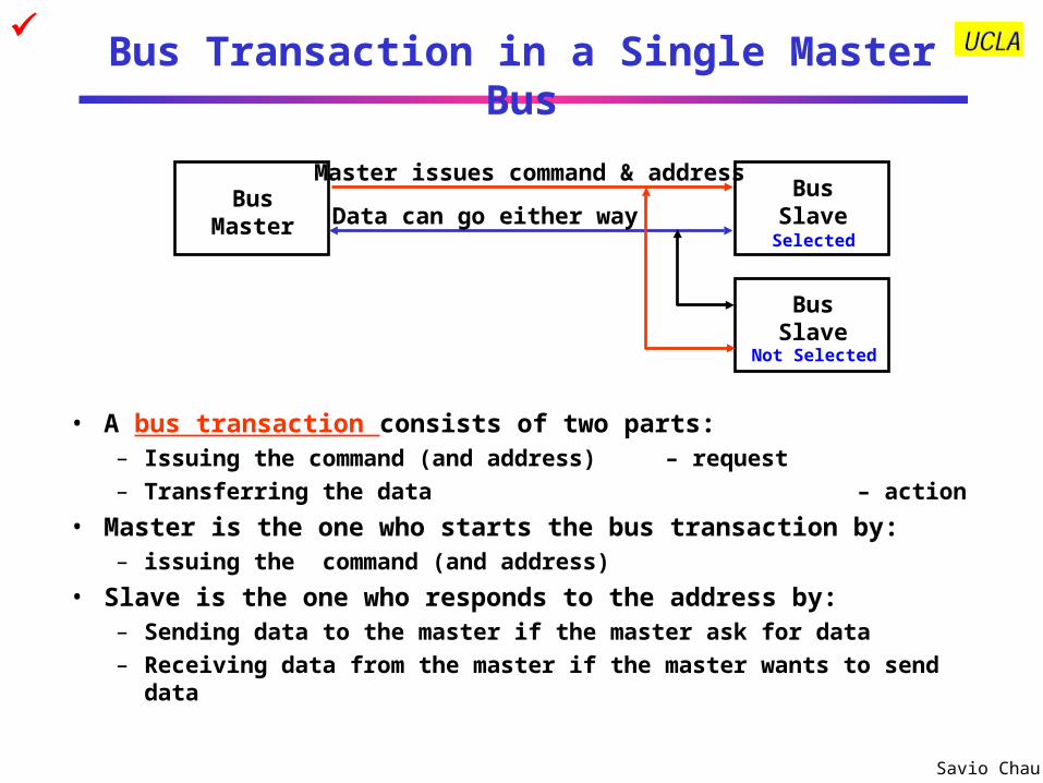
Bus Transaction in a Single Master Bus
• A bus transaction consists of two parts:– Issuing the command (and address) – request
– Transferring the data – action
• Master is the one who starts the bus transaction by:– issuing the command (and address)
• Slave is the one who responds to the address by:– Sending data to the master if the master ask for data
– Receiving data from the master if the master wants to send data
BusMaster
BusSlave
Master issues command & address
Data can go either wayBus
SlaveSelected
Not Selected

Savio Chau
Multiple Master Bus
• More than one device has the capability to become bus master and initiate bus transactions
• The target device will respond whether it is master-capable or just a slave • Advantage: the workload can be shared among bus masters• Disadvantage: need to determine who has the right to use the bus -
arbitration
Most modern buses are multi-master
BusMaster
BusSlave
Master issues command & address
Data can go either way
BusMaster
Arbitration

Savio Chau
Arbitration in Multi-Master Bus
• Bus arbitration scheme:– A bus master wanting to use the bus asserts the bus request
– A bus master cannot use the bus until its request is granted
– A bus master must signal to the arbiter after finish using the bus
• Bus arbitration schemes usually try to balance two factors:– Bus priority: the highest priority device should be serviced first
– Fairness: Even the lowest priority device should never be completely locked out from the bus
• Bus arbitration schemes can be divided into four broad classes:– Daisy chain arbitration: single device with all request lines.
– Centralized, parallel arbitration: see next-next slide
– Distributed arbitration by self-selection: each device wanting the bus places a code indicating its identity on the bus.
– Distributed arbitration by collision detection: Ethernet uses this.

Savio Chau
Daisy Chain Bus Arbitration Scheme
• Advantage: simple• Disadvantages:
– Cannot assure fairness: A low-priority device may be locked out indefinitely
– The use of the daisy chain grant signal also limits the bus speed
BusArbiter
Device 1HighestPriority
Device NLowestPriority
Device 2
Grant Grant Grant
Release
Request
wired-OR

Savio Chau
Centralized Parallel Arbitration
• Used in essentially all processor-memory buses and high-speed I/O buses
• Disadvantage: Number of wires increases with devices
BusArbiter
DeviceA
Device N
DeviceB
Grant AReq A
Grant BReq B
Grant N
Req N
Data BusControl Bus

Savio Chau
Simple Implementation of a Bus Arbiter
Priority Logic (Fixed Priority)

Savio Chau
Increasing Transaction Rate on Multimaster Bus
• Overlapped arbitration– perform arbitration for next transaction during current
transaction
• Bus parking– master can holds onto bus and performs multiple
transactions as long as no other master makes request
• Overlapped address / data phases (previous slide)– requires one of the above techniques
• Split-phase (or packet switched) bus– completely separate address and data phases– arbitrate separately for each– address phase yield a tag which is matched with data
phase
• ”All of the above” in most modern mem busses

Savio Chau
Performance

Savio Chau
I/O System Performance
• I/O System performance depends on many aspects of the system (“limited by weakest link in the chain”):– The CPU speed – The bandwidth and latency of underlying interconnection
(buses)– The speed of the I/O controller– The speed of the I/O device– The speed of the I/O software (Operating System)– The efficiency of the software’s use of the I/O devices– The speed of the memory system:
• Internal and external caches
• Main Memory
• Two common performance metrics:– Throughput: I/O bandwidth– Response time: Latency
Savio Chau
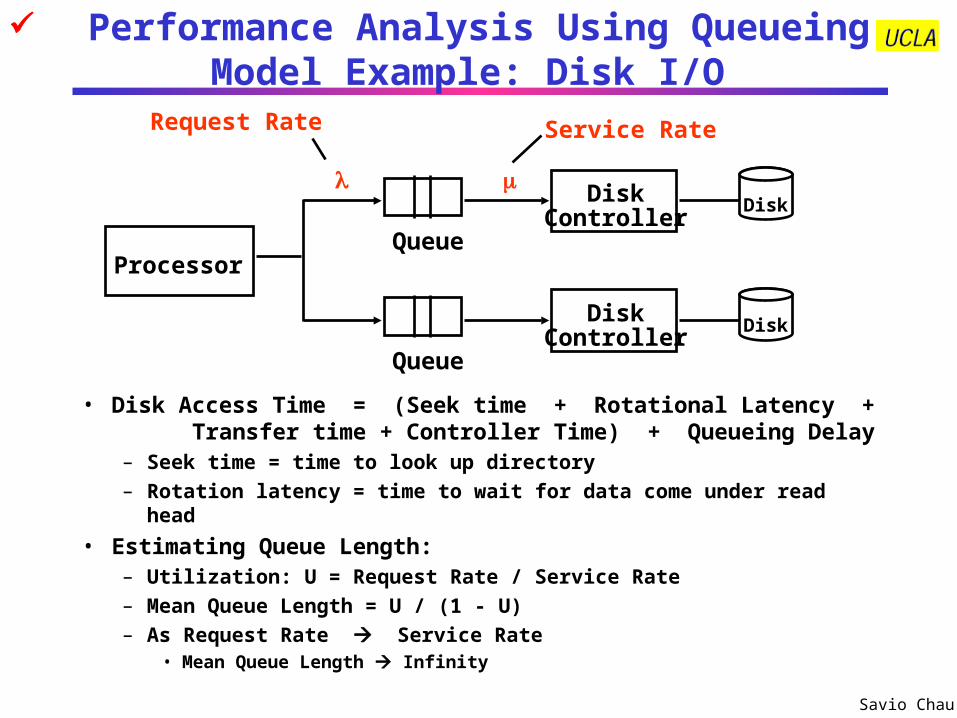
Performance Analysis Using Queueing Model Example: Disk I/O
• Disk Access Time = (Seek time + Rotational Latency + Transfer time + Controller Time) + Queueing Delay
– Seek time = time to look up directory – Rotation latency = time to wait for data come under read head
• Estimating Queue Length:– Utilization: U = Request Rate / Service Rate– Mean Queue Length = U / (1 - U)– As Request Rate Service Rate
• Mean Queue Length Infinity
ProcessorQueue
DiskController
Service RateRequest Rate
Queue
DiskController
Disk
Disk

Savio Chau
Disk Access Time Example
• 512 byte sector, rotate at 5400 RPM, advertised seeks is 12 ms, transfer rate is 4 BM/sec, controller overhead is 1 ms, queue idle so no service time
• Disk Access Time = Seek time + Rotational Latency + Transfer time + Controller Time + Queueing Delay
= 12 ms + 0.5 / 5400 RPM + 0.5 KB / 4 MB/s + 1 ms + 0
= 12 ms + 0.5 / 90 RPS + 0.125 / 1024 s + 1 ms + 0
= 12 ms + 5.5 ms + 0.1 ms + 1 ms + 0 ms
= 18.6 ms
– Note: rotation latency is 0.5 rotation on the average
• If real seeks are 1/3 advertised seeks, then its 10.6 ms, with rotation delay at 50% of the time!

Savio Chau
Simple Producer-Server Model
• Throughput:– The number of tasks completed by the server in unit time– In order to get the highest possible throughput:
• The server should never be idle• The queue should never be empty
• Response time:– Begins when a task is placed in the queue– Ends when it is completed by the server– In order to minimize the response time:
• The queue should be empty• The server should be idle
Producer ServerQueue

Savio Chau
Performance Enhancement
• In general throughput can be improved by:– Throwing more hardware at the problem– Reducing load-related overhead
• Response time is much harder to reduce:– Function of technology
Producer
ServerQueue
QueueServer

Savio Chau
I/O Performance Enhancement Example: Increasing Bus Throughput
• Separate versus multiplexed address and data lines:– Address and data can be transmitted in one bus cycle if separate
address and data lines are available
– Cost: (a) more bus lines, (b) increased complexity
• Data bus width:– By increasing the width of the data bus, transfers of multiple words
require fewer bus cycles
– Example: SPARCstation 20’s memory bus is 128 bit wide
– Cost: more bus lines
• Block transfers:– Allow the bus to transfer multiple words in back-to-back bus cycles
– Only one address needs to be sent at the beginning
– The bus is not released until the last word is transferred
– Cost: Increased complexity and slower response time
• Pipelined Bus– Initiate next address phase during current data phase
– Cost: Increased complexity in bus control logic

Savio Chau
Expandibility

Savio Chau
Expandability
• Depends on Many Factors– Bus Length: Constrained by bit rate and cross-talk– Bus Driver Capability: Constrained by how much current can
source or sink by each node– Topology
• The number of devices in star or point-to-point configuration must be determined ahead of time
• Multi-drop buses are more expandable. Devices can be added any time, but the shared bus media will eventually become a bottleneck
• Point-to-point buses is much more scalable
– Built-In Expandability: Some buses support expansion by using repeaters and bridges
– Bus Bandwidth: The higher bandwidth of the I/O system, the more nodes it can support
– Processor Performance: Faster processor can handle more I/O operations and thus more I/O devices

Savio Chau
Failure Handling

Savio Chau
Resilience in the face of failure• Two terms that are often confused:
– Reliability: Is anything broken? There are two views:• Is the system broken (e.g., your computer crashed)?• Is the component (i.e., I/O devices) broken (e.g. printer not working)?
– Availability: Is the system available to the user?
• System Reliability can be improved by:– Component reliability
• Can only be improved by building more reliable components using better quality control or more advanced technology
– Fault tolerant design • Adding fault detection logic and redundant components
– Building with fewer components• This contradicts fault tolerant design. Careful trade-off is required.
– Better environmental conditions
• Availability can be improved by:– Have a good repair personnel
– Have sufficient spare components

Savio Chau
Basic Ideas of Fault Tolerance Design
• Fault Detection:Hareware techniques– Using duplicate-and-compare– Using coding technique
Software techniques– Watchdog timer
• Fault Isolation: to identify the location of the faulty component– Usually done in softare
• Fault Recovery– Replace the faulty component with a backup component– Sometimes fault recovery can be done by masking the
fault with error correction code or voting
Savio Chau
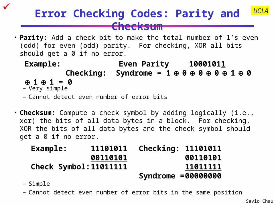
Error Checking Codes: Parity and Checksum
• Parity: Add a check bit to make the total number of 1’s even (odd) for even (odd) parity. For checking, XOR all bits should get a 0 if no error.
– Very simple
– Cannot detect even number of error bits
• Checksum: Compute a check symbol by adding logically (i.e., xor) the bits of all data bytes in a block. For checking, XOR the bits of all data bytes and the check symbol should get a 0 if no error.
– Simple
– Cannot detect even number of error bits in the same position
Example: Even Parity 10001011Checking: Syndrome = 1 0 0 0 1 0 1 1 =
0
Example: 11101011 Checking: 11101011 00110101 00110101
Check Symbol: 11011111 11011111Syndrome = 00000000

Savio Chau
Error Checking Code: Cyclic Redundancy CheckCapable to detect n error bits with a n-bit check symbolLet’s Use the Following Definitions:
M - The original frame to be transmitted, before adding the check symbol. It is k bits long.F - The resulting check symbol to be added to M. It is n bits long.T - The cascading of M and F. This is the resulting frame that will be transmitted. It is k+n bits long.P - The pre-defined CRC Polynomial. A pattern of n+1 bits. For the CRC to be effective, P should be a prime number.
The main idea behind the CRC algorithm is to find a value of F such that the reminder of T/P is zero. The process to create CRC is as follows:
1. Get the raw frame M and left shit it by n bits (I.e., M’ = Mn) 2. Shift Mn into a linear feedback shift register (LFSR) constructed according to P 3. After all the bits of Mn shifted, the reminder in the LFSR is the check symbol F 4. Append F to the M. The result is the frame T to transmit
CRC check process: Upon receiving T, verify the remainder of T/P is still zero.
1. Receive the frame T 2. Divide T by P by shifting all the bits of T into the LFSR 3. Check the remainder in the LFSR. There is an error in the frame if it is not zero.

Savio Chau
CRC Creation: Lets assume the check symbol F is 5 bits in length (n=5).
M = 1010001101 (k=10) M6 = 101000110100000 and,P = 110101 (n+1=6)
F can be computed by shifing M6 into a linear feedback shift register (LFSR). The feedback connections of the LFSR correspond to the bits of P.
F = 01110 = content of LFSR after all bits of M6 shifted in
Then the transmitted frame will be:
T = 101000110101110
Check: Shift All Bits of T into the LFSR and Check the RemainderWithout Error: Remainder = 00000
If Error Introduced During Transmission: T’ = 101000110100110With Error: Remainder = 01000
CRC Example
1 1 0 1 0 1
F/F F/F F/F F/F F/F+ + +
X5 X4 X3 X2 X1 X0
P(x) = X5 + X4 + X2 + 1
1010001101 00000(Generate) 1010001101 01110
1010001101 01110(Check) 1010001101 00000

Savio Chau
Operating System Support

Savio Chau
Processor Giving Commands to I/O Devices
• Two methods are used to address the device:– Special I/O instructions
– Memory-mapped I/O
• Special I/O instructions specify:– Both the device number and the command word
• Device number: the processor communicates this via a set of wires normally included as part of the I/O bus
• Command word: this is usually send on the bus’s data lines
• Memory-mapped I/O:– Portions of the address space are assigned to I/O device
– Read and writes to those addresses are interpreted as commands to the I/O devices
– User programs are prevented from issuing I/O operations directly• The I/O address space is protected by the address translation

Savio Chau
I/O Device Communicating to the Processor
• The Operating System needs to know when:– The I/O device has completed an operation– The I/O operation has encountered an error
• This can be accomplished in two different ways:– Polling:
• The I/O device put information in a status register
• The Operating System periodically check the status register
– I/O Interrupt:• Whenever an I/O device needs attention from the processor,
it interrupts the processor from what it is currently doing.

Savio Chau
Polling: Programmed I/O
• Advantage: – Simple: the processor is totally in control and does all the work
• Disadvantage:– Polling can consume a lot of CPU time
– Processor cannot respond to I/O events in real time unless polling the I/O devices at very high speed
Processor
Device #1 Device #2 Device #3 Device #4
Has data Has no data Has no data Has data
BusPoll #1 Poll #2 Poll #3 Poll #4Poll #1

Savio Chau
I/O Interrupt
• I/O interrupt is just like the exceptions except:– An I/O interrupt is asynchronous– Further information needs to be conveyed
• I/O interrupt is asynchronous with respect to instruction execution:– I/O interrupt is not associated with any instruction– I/O interrupt does not prevent any instruction from
completion• You can pick your own convenient point to take an interrupt
• I/O interrupt is more complicated than exception:– Needs to convey the identity of the device generating the
interrupt– Interrupt requests can have different urgencies:
• Interrupt request needs to be prioritized

Savio Chau
Interrupt Driven Data Transfer
• Advantage:– User program progress is only halted during actual transfer– “Immediate” response to I/O requests (most of the real time
systems use interrupt driven approach)
• Disadvantage, special hardware is needed to:– Cause an interrupt (I/O device)– Detect an interrupt (processor)– Save the proper states to resume after the interrupt (processor)
Processor
Device #1 Device #2 Device #3
Has no data Has no data Has no data
Has dataData served Has dataData served

Savio Chau
Hardware Implementation of I/O Interrupt
DQ DQ
DQ DQ
DQ
DQ
DQ
DQ
DQ
DQ
DQ
DQ
Interrupt Source 1
Interrupt Source 2
Decoder
Decoder
Interrupt Source 3
Interrupt Source 4
Interrupt Source 1
Interrupt Source 2
Interrupt Source 3
Interrupt Source 4
Clk
Clk
Interrupt Mask Reg
Interrupt Priority Logic
I/O Controller
Clk
Double Synchronizer
I/O Device 1
I/O Device 2
Data Bus (to/from Processor)
Address Bus (from Processor)
Processor
0
0
0
0
0
0
0
0
1Interrupt Register = 1000 means source 1
Device 1
Address for Device 1

Savio Chau
Programmer’s View of Interrupt
• Interrupt Target Address Options:
– General: Branch to a Common Address for all Interrupts; Software then Decodes the Cause and Figures Out What to do.
– Specific: Automatically Branch to Different Addresses Based on Interrupt Type and/ or Level — Known as Vectored Interrupt

Savio Chau
Issues in the Use of Interrupts• High Priority is Assigned to Devices that Require Rapid Response.
Otherwise, They Lose Data (e. g. Hard Disk Controllers).
• Low Priority Given to Slow Devices (e. g., Keyboard and Mouse)
• Higher Priority Interrupts can Interrupt Lower Priority Interrupts, But all Interrupt Routines Should Disable All Interrupts While They Are Saving State — Otherwise the System May Fail

Savio Chau
Disadvantages of Interrupt Driven I/O
• Large Overheads are Associated with Interrupt- Driven I/O
• For Each Item Transferred Within a Block of Data– Identify Interrupt– Save State of Process– Load State of Service Routine– Access Address and Count In Memory– Restore State of Process
• Results in– Inefficient use of CPU– Slow Response to I/ O
• Overhead can be Reduced by– Including a “block transfer” Instruction in Architecture– General Interrupt Used only at End of Block Transfer
Savio Chau
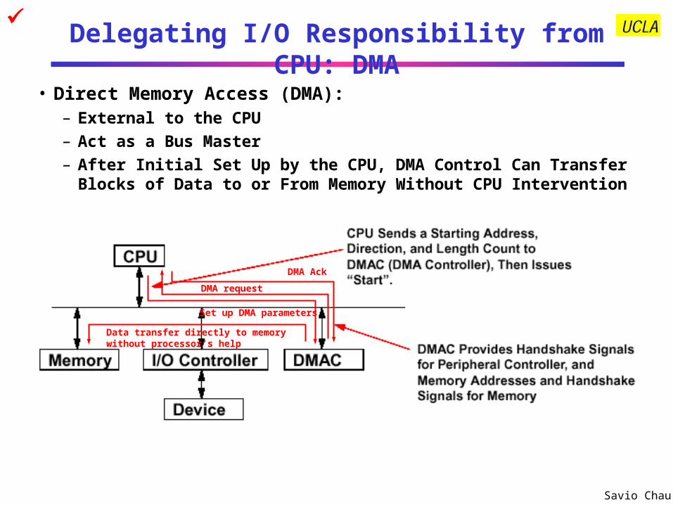
Delegating I/O Responsibility from CPU: DMA
• Direct Memory Access (DMA):– External to the CPU
– Act as a Bus Master
– After Initial Set Up by the CPU, DMA Control Can Transfer Blocks of Data to or From Memory Without CPU Intervention
Set up DMA parameters
DMA request
DMA Ack
Data transfer directly to memory without processor’s help

Savio Chau
Advantages of DMA
• Improves Response Time for Devices with Large Amounts of Data Transfers (Disks, Drums)
• Reduces CPU Overhead
• Data Transferred Directly to Memory
• Memory Addresses / Counts Computed in DMA Controller
• Cycle Stealing or Simultaneous Access (Multimodule Memory)
– Cycle Stealing: DMA controller has Priority Over CPU to Use Processor- Memory Bus. The CPU must Wait During the DMA Controller’s Infrequent Access to Memory
Savio Chau
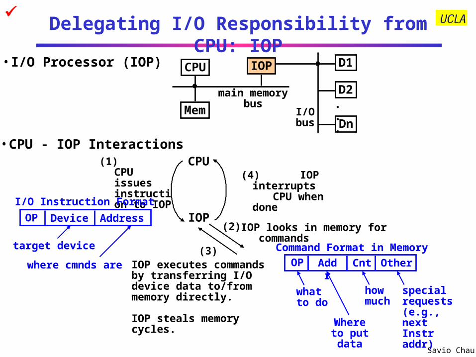
Delegating I/O Responsibility from CPU: IOP
CPU IOP
Mem
D1
D2
Dn
. .
.
main memorybus
I/Obus
CPU(1) CPU issues instruction to IOP
Command Format in Memory
(2)
(3)IOP executes commands by transferring I/O device data to/from memory directly.
IOP steals memory cycles.
(4) IOP interrupts CPU when done
IOP
target device
where cmnds are
I/O Instruction Format
IOP looks in memory for commands
OP
whatto do
Where to put data
howmuch
specialrequests (e.g., next Instr addr)
Addr Cnt Other
OP Device Address
• CPU - IOP Interactions
• I/O Processor (IOP)

Savio Chau
Responsibilities of the Operating System
• The operating system acts as the interface between:– The I/O hardware and the program that requests I/O
• Three characteristics of the I/O systems in OS:– The I/O system is shared by multiple program using the
processor– I/O systems often use interrupts (external generated
exceptions) to communicate information about I/O operations.
• Interrupts must be handled by the OS because they cause a transfer to supervisor mode
– The low-level control of an I/O device is complex:• Managing a set of concurrent events
• The requirements for correct device control are very detailed

Savio Chau
Operating System Requirements
• Provides abstraction for accessing devices:– Supply routines that handle low-level device operation
• Handles the interrupts generated by I/O devices• Provide protection to shared I/O resources
– Guarantees that a user’s program can only access theportions of an I/O device to which the user has rights
• Provide equitable access to the shared I/O resources– All user programs must have equal access to the I/O
resources
• Schedule accesses in order to enhance system throughput

Savio Chau
OS and I/O System Communication Requirements
• The Operating System must be able to prevent:– The user program from communicating with the I/O
device directly
• If user programs could perform I/O directly:– Protection to the shared I/O resources could not be
provided
• Three types of communication are required:– The OS must be able to give commands to the I/O
devices– The I/O device must be able to notify the OS when the
I/O device has completed an operation or has encountered an error
– Data must be transferred between memory and an I/O device
Savio Chau
I/O Implementation Example

Savio Chau
Specification of the Interface Signals
Proc Data Bus(Processor controller)
Proc Address Bus(Processor controller)
00000001
00050000
(go-read)
Controller Read Request(Controller device)
Write Enable(Processor controller)
Read Enable(Processor controller)
I/O Data Bus(Device Controller)
I/O Data Ready(Device Controller)
Valid data
00000000
00050001
100000000
00050001
Valid data
00050002
Processor
Proc Data Bus
Proc Addr Bus
Write Enable
Read Enable
I/O Controller
Read Request
I/O Data Bus
I/O Data ReadyI/O Device
Design an I/O controller that reads a 32-bit word from an I/O device under the command of the processor. The protocol and timing are as follows
Write Command Read Status Read Status Read Data

Savio Chau
Logic Design in RTLRTL of I/O Controller:Clock 1: Wait_Proc1: If proc_addr_bus = 0x00050002 & read_enable = 1(Decoding) Then proc_data_bus STATUS_REG
Goto Wait_Proc1 If proc_addr_bus = 0x00050001 & read_enable = 1
Then proc_data_bus DATA_REGGoto Wait_Proc1
If proc_addr_bus = 0x00050000 & write_enable = 1Then COMMAND_REG proc_data_bus
If COMMAND_REG != 0x00000001 Then Goto Wait_Proc1
Else read_request 1 Clock 2: Wait_Dev: If io_data_ready = 0(Get I/O data) Then goto Wait_Dev
Else DATA_REG io_data_busSTATUS_REG<31> 1read_request 0
If proc_addr_bus = 0x00050002 & read_enable = 1Then proc_data_bus STATUS_REG
Clock 3: Wait_Proc2: If proc_addr_bus = 0x00050001 & read_enable = 1(Proc get data) Then proc_data_bus DATA_REG
Else goto Wait_Proc2:If proc_addr_bus = 0x00050002 & read_enable = 1Then proc_data_bus STATUS_REG
Clock 4: Goto Wait_Proc1

Savio Chau
Realization of the Design in Hardware
Decoder
Command
Reg
Status
Reg
Data Reg
Control Logicmux
01
DRWrite
DRRead
SRRead
SRWrite
CRWrite
GoRead
io_data_ready
Read_request
Proc_addr
Proc_data
Read_Enable
Write_Enable
IO_data
DataReady
CRWrite = 1; DataReady = 0SRWrite = 0; SRRead = 1DRRead = 1;DRWrite = 0If GoRead, ReadRequest = 1, else ReadRequest = 0
CRWrite = 0SRWrite = 0; SRRead = 1DRRead = 0;If io_data_ready, DRWrite = 1Else DRWrite = 0If io_data_ready, DataReady = 1Else DataReady = 0If io_data_ready, ReadRequest = 0Else ReadRequest = 1
GoRead
GoRead
Io_data_readyy
Io_data_ready
GoRead
CRWrite = 0SRWrite = 0; SRRead = 1DRWrite = 0If Read Data Reg, DRRead = 1Else DRRead = 0DataReady = 0;ReadRequest = 0
Read Data Reg
Read Data Reg
CRWrite = 0SRWrite = 0; SRRead = 1DRRead = 1;DRWrite = 0DataReady = 0;ReadRequest = 0
I/O Controller Data Path and Control:

Savio Chau
Writing the Software Driver for the Processor
MIPS Device Driver for the I/O Controller:
# Assuming the I/O Controller is memory mapped# Assuming Command Register address (0x00050000) is in $s0# Assuming the GoRead command (0x00000001) is in $t0# Assuming Status Register address (0x00050001) is in $s1# When Status Register = 0x10000000, it indicates data in Data Register
is ready# Assuming Data Register address (0x00050002) is in $s2# The read data will be stored in $s3
sw $t0, 0($s0) # Proc writes GoRead to Command Reg
Wait: lw $t1, 0($s1) # Proc checks Status Regsubi $t2, $t1, 0x10000000bne $t2, $0, Wait # Wait if I/O data not readylw $s3 0($s2) # Proc read Data Reg

Savio Chau
I/O System Summary• Three Types of Buses
– Processor- Memory Buses– I/O Buses– Backplane Buses
• Bus Arbitration Schemes– Daisy Chain Arbitration: It Cannot Assure Fairness– Centralized Parallel Arbitration: Requires a Central Arbiter
• I/O Device Notifying the Operating System– Polling: It Can Waste a Lot of Processor Time– I/O Interrupt: Similar to Exception Except it is Asynchronous
• Delegating I/O Responsibility from the CPU– Direct Memory Access (DMA)

Savio Chau
Backup Slides I/O Devices Examples

Savio Chau
I/O Device Example: Display Monitor

Savio Chau
Memory Requirements of a Display Monitor• Character graphics (Black and White)
– 25 x 80 characters, 8 x 6 pixels/character, 1 bit/pixel, 30 frames/sec
Video RAM requirement = 96 kbits, I/O bus bandwidth = 2.88 Mbits/sec
• Bitmapped (pixel) graphics– Different Graphics Resolutions:
N= 640*480, 800x600, 1024x768, 1280x1024
30 frames/sec
– Black and white 1*N bits per screen, I/O bus bandwidth = 30*N kbits/sec
– Sixteen intensity gray scale 4*N bits, I/O bus bandwidth = 120*N kbits/sec
– 256 color display (RGB) 3*8*N bits, I/O bus bandwidth = 720*N kbits/sec
– True color (24 bits RGB) 3*24*N bits, I/O bus bandwidth = 2160*N kbits/sec
Example: What is the video memory and I/O bus bandwidth requirements to play a movie on a monitor, resolution 1280 x 1024, true color, 30 frames/sec
Video RAM = 1280 x 1024 pixels/frame x 9 bytes/pixel = 11.8 Mbytes
I/O Bus Bandwidth = 1280 x 1024 pixels/frame x 72 bits/pixel x 30 frames/sec
= 2.83 Gbits/sec
This can be handled by a 66 MHz, 64-bit PCI bus (bandwidth = 4.2 Gbits/sec)

Savio Chau
I/O Device Example: Magnetic Disks
Characteristics IBM 3090 IBM UltraStar Integral 1820
Disk diameter (inches) 10.88 3.50 1.80
Formatted data capacity (MB) 22,700 4,300 21
MTTF (hours) 50,000 1,000,000 100,000
Number of arms/box 12 1 1
Rotation speed (RPM) 3,600 7,200 3,800
Transfer rate (MB/sec) 4.2 9-12 1.9
Power/box (watts) 2,900 13 2
MB/watt 8 102 10.5
Volume (cubic feet) 97 0.13 0.02
MB/cubic feet 234 33000 1050

Savio Chau
Organization of a Hard Magnetic Disk
• Typical numbers (depending on the disk size):– 500 to 2,000 tracks per surface
– 32 to 128 sectors per track• A sector is the smallest unit that can be read or written
• Traditionally all tracks have the same number of sectors:– Constant bit density: record more sectors on the outer tracks
– Recently relaxed: constant bit size, speed varies with track location
Platters
Track
Sector

Savio Chau
Magnetic Disk Characteristic
• Cylinder: all the tacks under the head at a given point on all surface
• Read/write data is a three-stage process:– Seek time: position the arm over the proper
track– Rotational latency: wait for the desired sector to
rotate under the read/write head– Transfer time: transfer a block of bits (sector)
under the read-write head
SectorTrack
Cylinder
HeadPlatter
• Average seek time as reported by the industry:– Typically in the range of 8 ms to 12 ms
– (Sum of the time for all possible seek) / (total # of possible seeks)
• Due to locality of disk reference, actual average seek time may:– Only be 25% to 33% of the advertised number

Savio Chau
Typical Numbers of a Magnetic Disk• Rotational Latency:
– Most disks rotate at 3,600 to 7200 RPM– Approximately 16 ms to 8 ms per revolution– An average latency to the desired
information is halfway around the disk: 8 ms at 3600 RPM, 4 ms at 7200 RPM
SectorTrack
Cylinder
HeadPlatter
• Transfer Time is a function of :– Transfer size (usually a sector): 1 KB / sector– Rotation speed: 3600 RPM to 7200 RPM– Recording density: bits per inch on a track– Diameter typical diameter ranges from 2.5 to 5.25 in– Typical values: 2 to 12 MB per second– Indicate What Type of Information is on the Data Lines
• A Bus Transaction Includes Two Parts:– Sending the Address and Control
– Receiving or Sending the Data

Savio Chau
Backup SlidesBus Surveys

Savio Chau
Memory Bus Survey (1993)
Characteristics MBus Summit Challenge XDBus Originator Sun HP SGI Sun Clock Rate (MHz) 40 60 48 66 Address lines 36 48 40 muxed Data lines 64 128 256 144 (parity) Data Sizes (bits) 256 512 1024 512 Clocks/transfer 4 5 4? Peak (MB/s) 320(80) 960 1200 1056 Master Multi Multi Multi Multi Arbitration Central Central Central Central Slots 16 9 10 Busses/system 1 1 1 2 Length 13 inches 12? inches 17 inches

Savio Chau
Backplane Bus Survery
Characteristics SBus TurboChannel MicroChannel PCI Originator Sun DEC IBM Intel Clock Rate (MHz) 16-25 12.5-25 async 33 Addressing Virtual Physical Physical Physical Data Sizes (bits) 8,16,32 8,16,24,32 8,16,24,32,64 8,16,24,32,64 Master Multi Single Multi Multi Arbitration Central Central Central Central 32 bit read (MB/s) 33 25 20 33 Peak (MB/s) 89 84 75 111 (222) Max Power (W) 16 26 13 25

Savio Chau
Serial I/O Bus Survey
Metrics IEEE 1394 (cable) SFODB (IEEE 1393) FIBRE CHANNEL I2C
Effective Bandwidth
100, 200, 400 Mbps 200 Mbps, 1 Gbps 1 Gbps 100, 400 Kbps
Power 1 W/node 5 W/node 2 W/node 5 mW/node
Multi-master Yes Yes Yes Yes
Fault Tolerance CRC for error detection
Redundant ring with cross-strap bypass
links
Redundant ring with bypass links, CRC for error detection
No redundancy in topology. Error detection by Ack bit
Max. # Nodes 64 nodes 127 nodes Loop; 127Switched: no limit
Addressable up to 128 nodes or up to max loading of 400 pf
Max Bus Length 72 m (4.5 m/hop) 10 km, 100m node spacing
Fiber: 10 kmElectrical: 30 m
up to max loading of 400 pf
Protocol Overhead 8 % overhead with 278 byte payload data
10 % overhead with 53 byte payload
25 % overhead with 2168 byte payload
1 byte for address & R/W + 1 Ack bit per data byte

Savio Chau
Standard Buses
Characteristic VME Bus NuBus FutureBus IPI SCSI PCI
Bus Type Backplane Backplane Backplane I/O I/O Backplane
Bus width (signals) 128 96 96 16 8 48
Address / data Multiplexed?
Not Multiplexed
Multiplexed Multiplexed N/A Multiplexed Multiplexed
Data width (primary) 16- 32 bits 32 bits 32 bits 16 bits 8 bits 32 bits
Number of bus masters
Multiple Multiple Multiple Single Multiple Multiple
Arbitration Multiple daisy chain
Distributed self-
selection
Distributed self-
selection
N/A Self-selection
Any
Clocking Async Sync Async Async Either Sync
Bandwidth, 150ns memory single word
12. 9 MB/s 13. 2 MB/s 15. 5 MB/s 25. 0 MB/s 5.0 MB/s or 1.5 MB/s
16. 5 MB/s
Bandwidth, 150ns memory, multi word
(infinite length)
13. 6 MB/s 26. 4 MB/s 20. 8 MB/s 25. 0 MB/s 5.0 MB/s or 1.5 MB/s
132 MB/s
Maximum number of devices
21 16 20 8 7 10
Maximum bus length 0.5 meters 0.5 meters 0.5 meters 50 meters 25 meters 0.5 meters
Standard name IEEE 1014 IEEE 1196 IEEE 869. 1 ANSI X3.129 ANSI X3.131 PCI