Sauna control unit - Sven Saunassven-saunas.co.uk/images/controllers/Econ D3 Control Manual.pdf ·...
33
1 GB Sauna control unit Druck Nr. 29344531en 22.13 ECON D3 GB Installation and operating instruction
Transcript of Sauna control unit - Sven Saunassven-saunas.co.uk/images/controllers/Econ D3 Control Manual.pdf ·...

1GB
Sauna control unit
Druck Nr. 29344531en 22.13
ECON D3
GB Installation and operating instruction
English
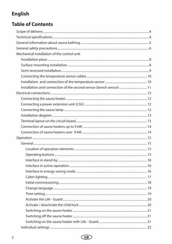
Table of Contents
Scope of delivery ...........................................................................................................................................4
Technical specifications ..............................................................................................................................4
General information about sauna bathing ..........................................................................................5
General safety precautions ........................................................................................................................6
Mechanical installation of the control unit
Installation place .....................................................................................................................................8
Surface-mounting installation ...........................................................................................................8
Semi-recessed installation ...................................................................................................................9
Connecting the temperature sensor cables ............................................................................... 10
Installation and connection of the temperature sensor ....................................................... 10
Installation and connection of the second sensor (bench sensor) .................................... 11
Electrical connections............................................................................................................................... 12
Connecting the sauna heater .......................................................................................................... 12
Connecting a power extension unit (LSG) .................................................................................. 12
Connecting the sauna lamp ............................................................................................................. 12
Installation diagram ............................................................................................................................ 13
Terminal layout on the circuit board. ............................................................................................ 13
Connection of sauna heaters up to 9 kW .................................................................................... 14
Connection of sauna heaters over 9 kW ..................................................................................... 14
Operation ...................................................................................................................................................... 15
General ..................................................................................................................................................... 15
Location of operation elements ............................................................................................... 15
Operating buttons ......................................................................................................................... 15
Interface in stand-by ..................................................................................................................... 16
Interface in active operation ...................................................................................................... 16
Interface in energy-saving mode ............................................................................................. 16
Cabin lighting .................................................................................................................................. 17
Initial commissioning ................................................................................................................... 18
Change language ........................................................................................................................... 19
Time setting ..................................................................................................................................... 19
Activate the Life - Guard .............................................................................................................. 20
Activate / deactivate the child lock ......................................................................................... 20
Switching on the sauna heater ................................................................................................. 21
Switching off the sauna heater ................................................................................................. 21
Switching on the sauna heater with Life - Guard ............................................................... 21
Individual settings ............................................................................................................................... 22
2 GB

Cabin temperature ........................................................................................................................ 23
Life - Guard ....................................................................................................................................... 23
Auto-Stop (heating time limitation) ........................................................................................ 24
Preselection time (pre-set timer) .............................................................................................. 26
Activate the preselection time .................................................................................................. 27
Deactivate the preselection time ............................................................................................. 27
Extend the time setting for sauna time .............................................................................................. 28
Unit fuses ....................................................................................................................................................... 28
Error messages and troubleshooting.................................................................................................. 29
The device switch (Switch-off ) .............................................................................................................. 30
Service Address: .......................................................................................................................................... 31
Guarantee ..................................................................................................................................................... 31
Handling procedures for return shipments (RMA) - Details for all returns ! .......................... 32
3GB

Scope of delivery
(changes without prior notice reserved)
The package contents includes:
Control unit
1. Temperature sensor, consisiting of: sensor board with overheating protection fuse, KTY-sensor, sensor housing, two 3x25 mm fastening screws and 2,0 m long sensor cable.
2. Plastic bag with three 4 x 20 mm fastening screws.
3. 1 replacement overheating protection fuse (inside control unit housing)
4. Installation and operating manual
Technical speci!cations
Rated voltage: 400 V 3 N 50 Hz AC
Power output: max. 9 kW resistive load (AC1 - operation).
Power extension: up to 36 kW possibile with an optional LSG device.
Heating time limitation: 6 h, 12 h, without limitation (via jumper setting)
Display: LCD Display 65 x 37 mm, alphanumeric, with backlighting
Dimensions (H x W x D): 220 x 250 x 67 mm
Protection class: IPx4 as per EN 60529 splash proof
Temperature control range: 30 - 115°C
Temperature sensor system: KTY-sensor with safety overheating limiter fuse 142°C
Control characteristics: Digital two-point control
Output for cabin lighting: max. 100 W
Ambient temperatures: -10°C to +40°C
Storage temperatures: -20°C to +70°C
4 GB
Dear customer
You have purchased a high-quality technical device with which you will have years of sauna fun. This sauna control unit was designed and inspected according to the current European safety standards and manufactured at the facto-ry in accordance with the quality management standard DIN EN ISO 9001:2000.
This detailed installation and operation manual has been prepared for your information. Please observe in particular the important notes and the information on electrical connection.
We wish you exhilarating recreational experience and lots of fun with your sauna!
Intended use
This sauna control unit is exclusively intended for the control of the sauna heater in a sauna cabin.
Any other use over and above the intended purpose is not considered as appropriate use! Compliance of the standard operation, mainte-nance and repair conditions is also an element of appropriate use.
The manufacturer cannot be held liable for deviating, unauthorized alterations and any re-sulting damages: the initiator of these changes bears the full risk.
General information
Please check whether the unit has arrived in per-fect condition. Any transport damages should be immediately reported to the freight forwarder delivering the goods or you should contact the company that shipped the goods.
Please note that you will only be able to achieve an optimum sauna climate if the cabin with its air intake and ventilation, the sauna heater and the control unit are aligned to each other.
Please observe the information and stipulations made by your sauna supplier.
Sauna heaters heat up your sauna cabin using heated convective air. Here, fresh air is drawn in from the air intake which, when heated, rises upwards (convection) and is then circulated within the cabin. Part of the used air is pushed out through the vent in the cabin. This creates a typical sauna climate which can achieve tempe-ratures of approx. 110°C measured directly under the ceiling of your sauna, dropping in tempera-ture to approx. 30-40°C towards the $oor. It is therefore not unusual to measure temperatures of 110°C on the temperature sensor hanging over the heater, whilst the thermometer hanging on the sauna wall, approx. 20-25 cm under the cabin ceiling, only indicates 85°C. The bathing temperature generally lies between 80°C and 90°C in the area of the upper bench when the temperature is set to maximum.
Please note that the highest temperatures are always generated over the sauna heater and that the temperature sensor and the safety limiter must be mounted there in accordance with the control unit installation instructions.
When heating up for the first time, you may notice a slight smell caused by evaporating lubricants used in production processes. Please ventilate your cabin before beginning your sauna bath.
5GB

General safety precautions
This device can be used by children aged 8
upwards and by persons with physical,
sensory, or mental disabilities, or who
have inadequate experience and knowl-
edge if they are supervised or if they have
received adequate instruction in how to
use the device safely and understand the
associated risks. Children may not play
with this device. Children may not clean
or carry out any user maintenance if un-
supervised.
Children are to be supervised in order to
make sure that they do not play with this
device.
Attention: It is forbidden to install the
control box in a closed switch cabinet or
behind a wooden panelling!
The electrical installation may be done only
by a quali#ed electrical technician.
You must comply with the regulations of
your power supply company and applica-
ble VDE regulations (DIN VDE 0100).
WARNING: Never attempt repairs or
installations yourself, as this could result
in serious injury or death. Only a quali#ed
technician may remove the housing cover.
Please note the dimensions in the assembly
instructions, especially when installing
the temperature sensor. The temperature
above the oven is critical for the temper-
ature setting. The temperature can be
held within operating parameters and
a minimal temperature gradient inside
the bench area of the sauna cabin can be
achieved only if unit is assembled correct-
ly.
The device may only be used as intended as a
control unit for sauna ovens up to 9 kW (up
to 36 kW when combined with a contactor
box).
Completely disconnect the control unit from
the electrical circuit, i.e. $ip all circuit
breakers or the main circuit breaker during
each installation or repair.
Please note the safety and installation infor-
mation from the sauna oven manufactur-
er.
Always heed the speci#cations and instruc-
tions of the cabin manufacturer, too.
6 GB

Attention!
Dear customer,
according to the valid regulations, the
electrical connection of the sauna heat-
er and the control box has to be carried
out through the specialist of an author-
ized electric shop
We would like to mention to the fact
that in case of a warrenty claim, you
are kindly requested to present a copy
of the invoice of the executive electric
shop.
When using control units that
o#er the possibility of external access
(GSM-module, remote button, etc.) or
time-delayed switching (preselection
time, weekly timer, or similar) a trig-
ger guard with covered heating unit is
required. (cover protection type 1-5 or
S-Guard).
7GB

Installation of the control unit
Wall installation
The control unit may only be mounted outside the sauna cabin. It is advisable to select the out-side wall of the cabin to which the sauna heater is %xed from the inside as mounting position. If ductwork is already provided for electrical in-stallations then the position of the control unit is predetermined by that. Please follow the in-structions for installation:
Fig. 1
1. The 3 mm diameter boreholes for the sup-plied wood screws 4 x 20 mm are drilled according to the dimensions shown in Fig. 3 + 3.1.
2. Insert one of the wood screws into the top center hole. The control unit is hooked onto this screw. Therefore, leave the screw out by approx. 3 mm (Fig. 3.2).
3. Hook the control unit onto the 3 mm protru-ding screw in the upper mounting hole.
Insert the supplied rubber grommets into the openings at the rear wall of the housing and insert the connecting cable through the-se openings.
Fasten the housing bottom at the two bot-tom openings (Fig. 4) %rmly to the cabin wall.
Fig. 3
Eye
leve
l
Fig. 3.2
3
Upper mounting hole
Mounting holes
Fig. 3.1
approx. 34 cm
17 c
m
17.7 cm
Eye
leve
l
Remove the control device cover. In order to do this loosen the screw at the top of the housing and pull the housing top upward while swivel-ling (Fig. 1).
Surface-mounted installation
Fig. 4
Feed-through for:Mains cableHeater cableEvaporator cableLampFan
Feed-through for sensor lines
8 GB

Fig. 6
Feed-through for:Mains cableHeater cableEvaporator cableLampFan
Feed-through for sensor lines
Recessed installation
1. Cut out a wall section that is at least 3.5 cm deep according to the dimension in Fig. 5.
Insert the supplied rubber grommets into the openings at the rear wall of the housing and insert the connecting cables through these openings.
Place the control unit into the wall opening and fasten it with 4 wood screws.
208
202
Eye
leve
l
Holes to fasten the con-trol unit inside the wall opening.
Fig. 5
9GB

Connection of the sensor cables
You should not lay sensor and power supply ca-bles together, or draw them through the same feedthrough. This can lead to interferences in the electronics, such as “$uttering” in the relays, which may damage the control unit. If it is nec-essary to lay the cables down together, or if the line is longer than 3 m, use a shielded sensor cable (4 x 0.5 mm²).
Connect the shielding to ground in the control unit.
Please observe that the following dimensions relate to the values stipulated during the unit approval as per norm EN 60335-2-53. The heat-er sensor must always be installed at the point where the highest temperatures are to be ex-pected. Illust. 7 - 9 give you an overview of the mounting point of the sensor.
1. Mount the oven sensor in cabins up to 2 x 2m according to Fig. 7 and 8, in larger cabins ac-cording to Fig. 7 and 9.
20 cm
Fig. 7
housing
red
red
sensor boardsensor board
Sen
sor
wh
ite
(lim
iter
)
wh
ite
(lim
iter
)
Fig. 10
Fig. 8 Fig. 9
2. Drill a hole in sauna ceiling panel to lead the cable through, preferably through the mid-dle of one of the wooden boards.
3. Lead the sensor cable through the drilled hole and connect it to the sensor line accord-ing to Fig. 10.
4. The cables for the limiter fuse (white) and the temperature sensor (red) shall be connected to the sensor circuit board as per Fig. 10. In-sert the sensor board into the casing.
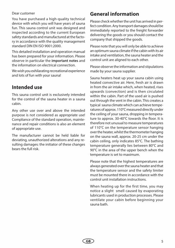
5. Lead the sensor cables through the right-hand cable intake into the control unit. Lay the sensor cables inside the control unit as shown in Fig. 11. Connect the sensor cables to the board as shown in Fig. 12. In order to do this, pull the plug X2 from the circuit board and plug it back in after the connec-tion of the sensor.
Installation of the tempera-
ture sensor
10 GB
X1
X2
F1
Example of the error message for overheating limiter fuse (DE)
Attention! Make sure not to confuse the sensor cables at X2 connector! This may cause the F2 fuse to burn, for replacement see page 29.
Hole
Sauna ceiling
Jumper for heating time limitation setting: 6 h, 12 h, unlimited
centre sensor housing in the middle of the plank
Second temperature sensor (optional)
Humidity sensor (op-tional, only Econ H3)
sensor cables
Fig. 11
142°C
KTY 1
0/5
Sensor
Limiter
X2
weiß / white
rot / red
Fig. 12
6. After completed installation and correct commissioning of the control unit, the line for overtemperature protection must be checked for short-circuits. In order to do this, disconnect one of the white cables in the sensor casing. The respective error message shall appear in the display.
12:00
Sensor -
break
11GB
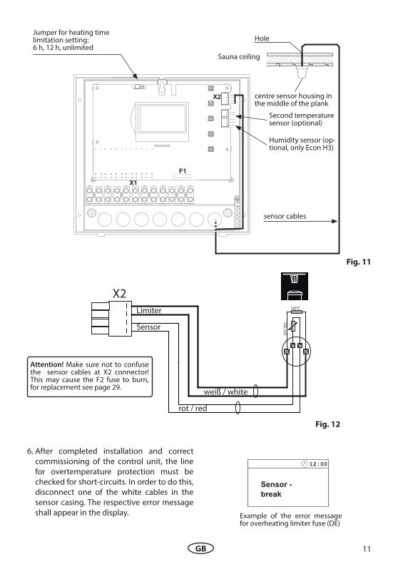
Installation of the optio-
nal second temperature
sensor (bench sensor)
Installation place: The bench sensor shall be mounted to the ceiling over the rear wall bench opposite to the heater as described in the in-stallation of the bench sensor.
If the sensor is connected correctly, the control unit shall automatically recognise it once the mains voltage has been switched on again.
bench sensor
By faults of the second sensor the following er-ror messages will be displayed:
„Sensor break“ - interruption of the sensor cir-cuit (e.g. faulty contact).
or
„Sensor short“ - short circuit of the sensor
In this case, the sensor must be checked by a specialist and replaced if necessary. At room temperature 20 °C, the sensor has approx. 2 kΩ resistance.
In order to keep on operating your sauna cabin despite the second sensor fault switch the unit from power supply, disconnect the cable con-nection to the second sensor and restore the power supply.
Once the problem has been solved, the control unit shall recognise the sensor after it has been re-connected and the mains voltage has been switched on again
The bench sensor is connected with a 2-core silicone cable from the sensor pcb to the termi-nals on the right-hand side of the main board of the sauna controller (X2), as shown below.
Bankfühler2nd temper. sensor
TemperaturfühlerTemperature sensor
142°C
KTY
11/5
X2 weiß
rot
12 GB

Electrical connection
The electrical connections may only be car-
ried out by a certi!ed electrician in compli-
ance with the guidelines of the local power
supply company and applicable legal regu-
lations (e.g. VDE norms for Germany).
In general, there may be only one permanent connection line to the network. Futhermore equipment should be provided that makes it possible to disconnect the system on all phases from the power supply with a contact gap of minimum 3 mm.
All electrical installations and all connection lines that are installed inside the sauna cabin must be suitable for an ambient temperature of at least 170 °C.
The power supply line shall be laid to the con-trol unit and connected to the power input ter-minals.
Install the sauna heater and the vaporizer in front of the air intake according to the manu-facturer’s installation instructions.
Run the silicone line through the ductwork to the power unit and connect it to the appropri-ate terminals as directed in the wiring diagram.
Note: In case there is no ductwork available drill a hole next to the air intake opening and run the heater line through this hole to the outside and to the appropriate terminals in the control unit. The silicone line must be buried to protect it from outside in$uences. Therefore, use a suit-able cable-duct or a PVC-pipe through which you can run the line up to the power unit.
Connection of the
sauna heater
The sauna lamp must have the protection class of at least IPx4 and should be resistant to the ambient sauna temperatures. The sauna lamp may be installed at any location but never close to the rising hot air of the heater.
Only heat resistant bulbs or other suitable illuminants may be used.
Connection of the
sauna lamp
LSG
Connection of the power
extension unit (LSG)
For details refer to the installation instructions of the respective LSG device.
13GB

Terminal layout on the main board
Installation diagram
435
4
5
= optional
400 V 3 N AC 50 Hz
LSG
ECON
X2
F1
F2
X1
Connector for tempera-ture sensor
Jumper for heating time limitation
Connection for the 2nd temp. sensor
at the reverse side of the board
14 GB
400 V 3 N AC 50 Hz
max. 100 W
NWVU NL1 L2 L3 Lig
ht
X1
N S1N
P max. 9 kW
ECON142°C
KT
Y 1
0/5
Sensor
Limiter
X2
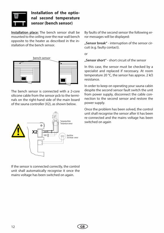
Connection of sauna heaters up to 9 kW
Attention! Always connect the N
terminal of the sauna heater!
400 V 3 N AC 50 Hz
max. 100 W
NWVU N S1L1 L2 L3 Lig
ht
X1
N N
ECON
P max. 9 kW
400 V 3 N AC 50 Hz
LSG
142°C
KTY
10/
5
Sensor
Limiter
X2
Connection of sauna heaters above 9 kW
A control lamp indicating active heating must be installed in the room or location of supervising sta; by commercial sauna cabins with disabled heating time limitation.
15GB

Operation
General details
Once the control unit has been installed with all components and all covers have been %xed, you can put your sauna unit into operation.
The following pages provide the detailed explanation, how to operate your control panel and make all necessary settings.
Operation elements
Operating buttons
= Sauna cabin lighting
= Sauna heating on / o; (stand-by)
= Programming mode (settings)
= Increase value / next function
= Reduce value / next function
MODE
MODE
the LCD-Display
operating buttons
16 GB

is shown if the control unit is in stand-by model
The display will automatically switch this in-terface from any state if no button has been pressed within >15 Sek.
12:00
30°C
5 : 59- - : - -
Temperature
Auto-stop
Start time
12:15
30°C
5 : 59- - : - -
Temperature
Auto-stop
Start time
12:34
30°C
30°C
Interface in Stand by
Interface in active operationis shown if the control unit is in active operation mode (heating is switched on).
The display will automatically switch this in-terface from any state if no button has been pressed within >15 Sek (during active heating).
Display of the heating process:
During the heating-up phase the bars behind the temperature %gures will %ll progressively.
Once the pre-set temperature has been rea-ched, the bars will remain %lled.
Interface in energy-saving mode
current time
the clock symbol
the light symbol (when the light is on)
12 : 00
In addition, the following symbols are displayed depending on the selected operating mode.
active child lock (keypad lock)
preset time (switching time preselec-tion)
If the control unit is not used for a longer time it will switch into the energy-saving mode.
A clock randomly moving across the display every minute will be shown after 5 minutes, similar to a PC screensaver. The backlight of the display is switched o; after an additional 15 minutes
By pressing any key you can wake the unti to the default “Stand-by” interface.
The following applies for all settings:
The following symbols are displayed at the top.
17GB

value to be adjusted
12:15
30°C
5 : 59- - : - -
Temperature
Auto-stop
Start time
12:15
30°C
5 : 59- - : - -
Temperature
Auto-stop
Start time
paramter to be adjusted
12:15
30°C
5 : 59- - : - -
Temperature
Auto-stop
Start time
12:15
30°C
5 : 59- - : - -
Temperature
Auto-stop
Start time
Temperature
In order to adjust the individual values to the particular desires, brie$y push the MODE -but-ton out of Stand-by.
The modi%able parameter will then be high-lighted in black and it is possible to select with the or - buttons the desired parameter.
By pushing the MODE -button again you will arrive at the programming level.
The name of the parameter is now blinking and the modi%able value is highlighted in black.
The value highlighted in black can now be changed with the or the - buttons.
All settings out of Stand-by are con%rmed by pressing MODE >3 s and are saved in the mem-ory of the unit.
The blinking of the parameter ends and the new value is now authoritative until another change is made.
If no button is pressed for >15 seconds the unit switches back to the default display. Changes made up to then will not be saved
Sauna cabin lighting
The cabin lighting is automatically switched on as soon as the sauna unit is switched on. In the top left of the display the - symbol is shown. When the sauna unit is switched o; the cabin lighting will switch o; with a delay of 30 min-utes.
Irrespective of the status of the sauna unit, the cabin lighting can be switched on or o; any-time with the button.
Parameters that blink on the display can be changed and are shown in these instructions as displayed.
18 GB

12:15
Life Guard
Initial commissioning
12:00
DE
GB
NL
PL
I
RU
00:00
0 : 00
Time of day
12:00
DE
GB
NL
PL
I
RU
00:00
12 : 00
Time of day
00:00
12 : 00
Time of day
00:00
12 : 15
Time of day
12:15
Life - Guard> 3 Sek
> 3 Sek
> 3 Sek
12:00
30°C
5 : 59- - : - -20 minLife - Guard
Temperature
Auto-stop
Start time
MODE
MODE
MODE
MODE
19GB

Change language
12:15
12 : 15
Time of day
12:00
30°C
5 : 59- - : - -
Temperature
Auto-stop
Start time
MODE&
Set (change) time
12:00
DE
GB
NL
PL
I
RU
12:00
DE
GB
NL
PL
I
RU
12:00
DE
GB
NL
PL
I
RU
00:00
0 : 00
Time of day
> 3 Sek
12:00
12 : 00
Time of day
12:00
30°C
5 : 59- - : - -
Temperature
Auto-stop
Start time
MODE&
MODE
MODE
MODE
00:00
0 : 00
Time of day
00:00
12 : 00
Time of day
00:00
12 : 00
Time of day
00:00
12 : 15
Time of day
> 3 SekMODE
MODE
20 GB

Activate Life-Guard function
Life-Guard is a settable relatively short time, e.g. 20 minutes, after which the sauna heater will be switched o;, except for the cabin ligh-ting, if this function has been activated. After this time has elapsed the heater can be swit-ched on again by pushing the MODE - button for the set time.
In order to use this function you need to acti-vate it in the set-up menu. This may be done either during initial commissioning or later in normal operation.
12:15
12 : 15
Time of day
MODE&
12:15
Life Guard
12:15
Life - Guard
> 3 Sec
12:00
30°C
5 : 59- - : - -20 minLife - Guard
Temperature
Auto-stop
Start time
MODE
Activate / deactivate the child lock
12:00
30°C
5 : 59- - : - -
Temperature
Auto-stop
Start time
If the child lock is activated (the key symbol is visible in the top section of the display) only the cabin lighting can be switched. All other but-tons are without function. Activation / deacti-vation of the child lock can be done in stand-by as well as in operation mode. The unit can still be switched o; if in operation mode.
12:00
30°C
5 : 59- - : - -
Temperature
Auto-stop
Start time
& > 3 Sec
12:15
30°C
5 : 59- - : - -
Temperature
Auto-stop
Start time
12:00
30°C
5 : 59- - : - -
Temperature
Auto-stop
Start time
Activate
Stand by Operation
Deactivate
12:00
30°C
5 : 59- - : - -
Temperature
Auto-stop
Start time
& > 3 Sec
12:00
30°C
5 : 59- - : - -
Temperature
Auto-stop
Start time
12:15
30°C
5 : 59- - : - -
Temperature
Auto-stop
Start time
12:15
30°C
5 : 59- - : - -
Temperature
Auto-stop
Start time
12:15
30°C
5 : 59- - : - -
Temperature
Auto-stop
Start time
21GB

12:00
30°C
5 : 59- - : - -20 minLife - Guard
Temperature
Auto-stop
Start time
Switching on the sauna heater
12:00
30°C
5 : 59- - : - -
Temperature
Auto-stop
Start time
Switching o# the sauna heater
Auto-Stop time
12:15
30°C
5 : 59- - : - -
Temperature
Auto-stop
Start time
12:15
30°C
5 : 59- - : - -
Temperature
Auto-stop
Start time
12:00
30°C
5 : 59- - : - -
Temperature
Auto-stop
Start time
Switching the heater with Life-
Guard function12:00
30°C
5 : 59- - : - -20 minLife - Guard
Temperature
Auto-stop
Start time
12:15
30°C
5 : 59- - : - -
20 minLife - Guard
Temperature
Auto-stop
Start time
The sauna heater is now heating normally, wit-hout “Life - Guard”-time. To activate the function “Life - Guard”.
12:15
30°C
5 : 59- - : - -
20 minLife - Guard
Temperature
Auto-stop
Start time
MODE
After expiration of the “Life - Guard” - time the sauna heater is switched o; and the entire dis-play blinks:
12:15
30°C
5 : 59- - : - -
20 minLife - Guard
Temperature
Auto-stop
Start time
Restart heating:
MODE
Or switch the sauna heater o;:
12:00
30°C
5 : 59- - : - -20 minLife - Guard
Temperature
Auto-stop
Start time
> 3 Sec > 3 Sek
Notice:
In Life-Guard mode it is not possible to change the temperature or humidity settings as long as the control unit is in operation (active heating).
22 GB
Individual settings
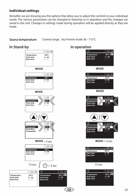
Sauna temperature
In Stand-by
12:15
30°C
5 : 59- - : - -
Temperature
Auto-stop
Start time
12:15
85°C
5 : 59- - : - -
Temperatur
Auto-Stop
Vorwahlzeit
> 3 sec
12:15
30°C
5 : 59- - : - -
Temperature
Auto-stop
Start time
12:00
30°C
5 : 59- - : - -
Temperature
Auto-stop
Start time
In operation12:15
30°C
5 : 59- - : - -
Temperature
Auto-stop
Start time
12:15
85°C
5 : 59- - : - -
Temperature
Auto-stop
Start time
12:15
30°C
5 : 59- - : - -
Temperature
Auto-stop
Start time
12:15
30°C
5 : 59- - : - -
Temperature
Auto-stop
Start time
15 sec.
12:00
85°C
5 : 59- - : - -
Temperature
Auto-stop
Start time
12:15
85°C
5 : 59- - : - -
Temperature
Auto-stop
Start time
MODE
MODE
MODE
12:15
85°C
5 : 59- - : - -
Temperature
Auto-stop
Start time
MODE
MODE
12:15
85°C
5 : 59- - : - -
Temperature
Auto-stop
Start time
> 3 sec.MODE
15 sec
12:15
85°C
5 : 59- - : - -
Temperature
Auto-stop
Start time
Control range: dry Finnish mode 30 - 115°C
> 3 sec
Hereafter we are showing you the options that allow you to adjust the controls to your individual needs. The various parameters can be changed in Stand-by or in operation and the changes are saved in the unit. Changes in settings made during operation will be applied directly as they are made.
23GB

12:00
30°C
5 : 59- - : - -
15 minLife - Guard
Temperature
Auto-stop
Start time
Life-Guard
12:00
30°C
5 : 59- - : - -
20 minLife - Guard
Temperature
Auto-stop
Start time
12:00
30°C
5 : 59- - : - -20 minLife - Guard
Temperature
Auto-stop
Start time
12:00
30°C
5 : 59- - : - -
20 minLife - Guard
Temperature
Auto-stop
Start time
MODE
MODE
In Stand-by
12:00
30°C
5 : 59- - : - -
20 minLife - Guard
Temperature
Auto-stop
Start time
MODE
Here you can set after what time the sauna heater shall be switched o; and by pushing the MODE - button again you can restart the heating for the pre-set “Life-Guard” time.
This setting can only be selected in Stand-by when the function “Life - Guard” is activated.
For instance you set 15 min time. If you do not press the MODE button within 15 minutes during active heating, the heater will switch o; once this time expires. If you press the „mode“ button, the heating will resume for the next 15 minutes.This feature provides you a convenience of a quick timer and is independent to the general hea-ting time limitation (auto-stop).
12:00
30°C
5 : 59- - : - -
15 minLife - Guard
Temperature
Auto-stop
Start time
12:15
30°C
5 : 59- - : - -
14 minLife - Guard
Temperatur
Auto-Stop
Vorwahlzeit
15 sek.
12:00
30°C
5 : 59- - : - -
15 minLife - Guard
Temperature
Auto-stop
Start time
> 3 Sec
24 GB

Auto-Stop (heating time limitation)Auto-Stop is the time to which the heating time is limited. The sauna heater automatically turns o; once this time has expired.
The time is adjustable from 0:01 to 6:00 hours. The extension of this time is possible with the jum-per setting and may be carried out only the specialist dealer. Please notice that such extension is only permitted for commercial sauna cabins (supervised commercial sauna cabins).
12:15
30°C
5 : 59- - : - -
Temperature
Auto-stop
Start time
12:00
30°C
5 : 59- - : - -
Temperature
Auto-stop
Start time
12:15
30°C
5 : 59- - : - -
Temperature
Auto-stop
Start time
MODE
12:15
30°C
- - : - -
55 : 59
Temperature
Auto-stop
Start time
12:15
30°C
- - : - -
53 : 59
Temperature
Auto-stop
Start time
MODE
12:15
30°C
- - : - -
53 : 59
Temperature
Auto-stop
Start time
MODE
In stand-by In operation
12:15
30°C
5 : 59- - : - -
Temperature
Auto-stop
Start time
MODE
12:15
30°C
5 : 59- - : - -
Temperature
Auto-stop
Start time
12:15
30°C
5 : 59- - : - -
Temperature
Auto-stop
Start time
MODE
12:15
5 : 59
30°C
5 : 59- - : - -
Temperature
Auto-stop
Start time
12:15
3 : 59
30°C
- - : - -
Temperature
Auto-stop
Start time
12:15
3 : 59
30°C
- - : - -
Temperature
Auto-stop
Start time
MODE
25GB

12:15
3 : 30
30°C
- - : - -
Temperature
Auto-stop
Start time
> 3 sec.MODE
12:00
30°C
3 : 30- - : - -
Temperature
Auto-stop
Start time
12:00
30°C
3 : 30- - : - -
Temperature
Auto-stop
Start time
15 sek.
12:15
30°C
- - : - -
53 : 30
Temperature
Auto-stop
Start time
> 3 secMODE
12:15
30°C
3 : 30- - : - -
Temperature
Auto-stop
Start time
12:00
30°C
3 : 30- - : - -
Temperature
Auto-stop
Start time
15 sec.
12:15
30°C
3 : 29- - : - -
Temperature
Auto-stop
Start time
12:15
30°C
3 : 29- - : - -
Temperature
Auto-stop
Start time
> 3 sec
26 GB
Preselection time (pre-set timer)
12:15
30°C
5 : 59- - : - -
Temperature
Auto-stop
Start time
12:00
30°C
5 : 59- - : - -
Temperature
Auto-stop
Start time
12:15
30°C
5 : 59- - : - -
Temperature
Auto-stop
Start time
MODE
MODE
In stand-by
12:15
30°C
5 : 59- - : - -
Temperature
Auto-stop
Start time
12:15
30°C
5 : 5917 : - -
Temperature
Auto-stop
Start time
MODE
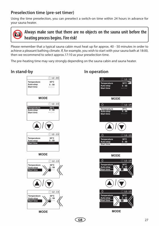
Using the time preselection, you can preselect a switch-on time within 24 hours in advance for your sauna heater.
Always make sure that there are no objects on the sauna unit before the
heating process begins. Fire risk!
Please remember that a typical sauna cabin must heat up for approx. 40 - 50 minutes in order to achieve a pleasant bathing climate. If, for example, you wish to start with your sauna bath at 18:00, then we recommend to select approx.17:10 as your preselection time.
The pre-heating time may vary strongly depending on the sauna cabin and sauna heater.
12:15
30°C
5 : 59- - : - -
Temperature
Auto-stop
Start time
12:15
30°C
5 : 59
17 : - -
Temperature
Auto-stop
Start time
MODE
In operation
12:15
30°C
5 : 59- - : - -
Temperature
Auto-stop
Start time
MODE
12:15
30°C
5 : 59- - : - -
Temperature
Auto-stop
Start time
12:15
30°C
5 : 59- - : - -
Temperature
Auto-stop
Start time
MODE
27GB

12:15
30°C
5 : 59- - : - -
Temperature
Auto-stop
Start time
12:15
30°C
5 : 5917 : - -
Temperature
Auto-stop
Start time
12:15
30°C
5 : 59
17 : 10
Temperature
Auto-stop
Start time
> 3 secMODE
12:15
30°C
5 : 59
17 : 10
Temperature
Auto-stop
Start time
12:15
30°C
5 : 59
17 : 10
Temperature
Auto-stop
Start time
12:15
30°C
5 : 59
17 : 10
Temperature
Auto-stop
Start time
15 sec
to preselected time
12:15
30°C
5 : 59
17 : 10
Temperature
Auto-stop
Start time
Deactivate the preselection time
12:15
30°C
5 : 59
17 : 10
Temperature
Auto-stop
Start time
to preselected time
12:15
30°C
5 : 59
17 : 10
Temperature
Auto-stop
Start time
12:15
30°C
5 : 59
17 : 10
Temperature
Auto-stop
Start time
> 3 secMODE
12:15
30°C
5 : 59- - : - -
Temperature
Auto-stop
Start time
15 sec
12:15
30°C
5 : 59
17 : 10
Temperature
Auto-stop
Start time
Activate the preselction time
12:15
30°C
5 : 59
17 : 10
Temperature
Auto-stop
Start time
12:15
30°C
5 : 59
17 : 10
Temperature
Auto-stop
Start time
12:15
30°C
5 : 59
17 : 10
Temperature
Auto-stop
Start time
28 GB

X2
F1
F2
Extension of the heating time limitationBy switching a jumper you can extend the time setting for sauna time from 6:00 to 12:00 hours or to unlimited operation time. Please notice that such extension is only permitted for certain com-mercial sauna cabins and may be restricted by the local legal regulations.
Open the control unit. The jumper is located in the middle of the top edge of the mainboard. Set jumper to the required position. Close the control unit. Restore the power supply.
Jumper for heating time limitation ( 6 hrs default)
X2
F1
F2
X1
Jumper
rear side of the board
Device fuses
On the rear sinde of board you will %nd the protective fuses. For replacement make sure to use the fuses of the same type and of the same resistance value.
F1 = T 2A Fuse primary electronics as well as light and fan
F2 = T 250 mA Fuse secondary electronics
Jumper 6:00 hours heating time limitation (factory default)
Jumper 12:00 hours heating time limitation
Jumper no heating time limitation
Such work must be carried out exclusively by an expert. Prior to any kind of work
disconnect the control unit from the power supply on all phases. (Switch o% main switch,
or trip the ground circuit breaker). Risk of electric shock!
29GB

Error messages and troubleshooting
The control unit continuously monitors the sensors for short circuits and interruptions. The error messages appear as follows:
Display Cause Remedy
12:00
Sensor -
break
12:00
Sensor short
-circuit
12:00
Thermal
fuse
= Interruption in the room sensor circuit.
The temperature sensor (KTY) is de-fective or the line to the temperature sensor is interrupted.
= Short-circuit in the room sensor circuit.
The temperature sensor (KTY) is de-fective, or the line to the temperature sensor is short-circuited.
= Interruption in the limiter circuit.
The thermal fuse (142°C) has tripped due to overheating or the line to the thermal fuse is interrupted.
= The fuse F2 is blown.
The fuse F2 is blown, for instance if the sensor cables (sensor and limiter lines) were confused.
Empty display, unit does not function.
Have cables and KTY che-cked by an expert. KTY at 20°C shall have ca. 2 kΩ and may need to be replaced.
Have cables and KTY che-cked by an expert.
Have the cables and ther-mal fuse checked by an ex-pert. Check the reasons for the possible overheating.
Check the sensor and the 2nd sensor (if installed) for correct connection at X2 connector. Replace the fuse F2 with the same type fuse.
30 GB

Press the switch on the left side of the rocker to the %rst latch (switch setting 0). The switch will be in the middle position. The unit is now completely switched o; (disconnected).
You will %nd the rocker switch on the top side of the control unit. You can completely discon-nect the control unit from the mains using this switch.
To turn the light on in the cabin while the unit is still disconnected push the left side of the ro-cker to the second latch (switch setting II).
To make the unit ready for operation, switch back to the initial position (switch setting I). The unit will return to stand-by mode.
Switch-o#
Unit turned on
(default Position I)
Unit switched on.
Position I.
Unit fully switched o;
Position 0.
Light switched on;
Unit switched o;.
Position II.
The device „Switch-o#“ switch Switch-o; by ECON control units
I 0 II
I 0 II
I 0 II
I 0 II
31GB
Please keep this address in a safe place toge-ther with the installation guide.
To help us answer your questions quickly and competently please provide the information printed on the type shield including the model, item no. and serial no., in all inquiries.
32 GB
tony
TextBox
Sven Saunas Ltd Unit 25 / 27 Sergeants Way Bedford MK41 0EH Tel 01234 356666 E-mail [email protected] www.sven-saunas.co.uk

GB