Satellite communication system’s detection
6
PRZEGLĄD ELEKTROTECHNICZNY (Electrical Review), ISSN 0033-2097, R. 87 NR 7/2011 249 Roman BERESIK, Milos SOTAK, Frantisek NEBUS, Jozef PUTTERA Armed Forces Academy Satellite communication system’s detection Abstract. In recent asymmetric warfare satellite communication systems play more and more important role in remote control of Improvised Explosive Devices (IED). Such systems are primarily used in environment where other communication technologies have either limited or no coverage in particular area. First stage in effective suppression of such systems misusage is possibility to monitor and in case of need cease down unacceptable communication. Paper deals with analysis of Thuraya communication system. The goal of paper is to present results of system analysis in terms of its configuration, time and frequency signal parameters. Base on achieved results the possible method on how to block IED triggering is outlined. Streszczenie. Asymetryczne satelitarne systemy komunikacyjne odgrywają ważną role w zdalnym sterowaniu urządzeniami wybuchowymi. Systemy tego typu są stosowane tam gdzie inne systemy komunikacji są limitowane. W artykule zaprezentowano system Thuraya. Przedstawiono parametry konfiguracji. (Detekcja satelitarnych sygnałów komunikacyjnych) Keywords: SATCOM, Thuraya, Signal Detection, Improvised Explosive Devices Słowa kluczowe: komunikacja satelitarna, zdalne sterowania urządzeniami wybuchowymi. Introduction Commercial satellite communications means play an increasingly vital role not only as public communication means but also in military operations, where is limited or no communication backbone available in particular area. Availability of commercial satellite systems cause the potential risk of their misusing from adversary side. There are several scenarios how satellite communication can be misused. On of them is to coordination of adversary attacks against friendly units during operations. Generally, commercial satellite systems are not hardened to be protected against deliberate attacks or jamming. This is the reason why analysis of satellite communication systems is important and in many cases crucial in order point out its vulnerabilities. In general, the satellite systems can be divided into two basic categories [1, 2]. The first category involves Geostationary Earth Orbit (GEO) systems such as INMARSAT and THURAYA, and the second one involves Non-geostationary Earth Orbit (Non-GEO) systems. The main systems being included in this category are GLOBALSTAR, IRIDIUM and ICO as well. Every system has its own architecture, coverage, signal structure and system of frequency management. In general, main approach for satellite communication system signal analysis is to detect of satellite terminals activities in particular areas both in uplink and downlink direction in order to identify particular satellite communication systems, analyze signal structure and if it is possible to identify single user terminal within data stream. It is important to point out that satellite systems share same frequency band for uplink and downlink direction which is dedicated for SATCOM systems. The paper presents the analysis of the Thuraya satellite system, time and frequency signal analysis and outcomes achieved during practical experiments. Thuraya system overview The Thuraya satellite system launched in 2001 by a Private company Thuraya Satellite Telecommunications Co. Ltd, based in United Arab Emirates allows 2 portable terminals to communicate on a local cover Middle East, North and Central Africa, Europe, Central Asia and the Indian subcontinent. The scheduled life-span of the system is 12-15 years. The supplied services are: voice, fax and data in 9,6 kb/s, SMS, INTERNET at the bit rate of 9,6Kb/s, and localization by GPS, allowing the user to know or to transmit its position by voice or by SMS. The system has the capacity for 13,750 simultaneous voice circuits with a call blocking probability of 2%. The Thuraya-2 satellite acts as an on-ground spare. The Thuraya system has been designed to be compatible with the GSM network. The dual-mode hand-held terminals are of a similar dimension to current GSM phones. Vehicular dual-mode phones are also supported, as are satellite- mode only fixed terminals and payphones. The mobile link operates in the L band, specifically the 1626.5–1660.5 MHz for uplink (UL) and 1525.0–1559.0 MHz for downlink (DL) bands. The Thuraya system is defined by global mobile radio ETSI standards (see more [4]). The composition of the Thuraya system elements is shown in Figure 1. The system includes one or more geostationary satellites, a Satellite Operations Center (SOC), a number of Gateway Stations (GS), and a large number of user terminals, referred to as Mobile Earth Stations (MES). The range of possible MESs includes hand portable terminals (handsets), vehicle terminals, and fixed terminals. The Gateway stations have external interfaces to existing fixed telecommunications infrastructure as well as to the GSM mobility management networks. Fig.1. Thuraya system elements [4] A GS includes one or more Gateway Transceiver Subsystems (GTS) which correspond to a GSM BTSs, one or more Gateway Station Controllers (GSC), which correspond to a GSM BSCs, one or more Mobile Switching Centers (MSC) which may be GSM MSCs, and one Traffic Control Subsystem (TCS) which has no corresponding functional element in the GSM base station. The Thuraya TCS is required to support position based services, optimal routing and other satellite specific services and features, not
Transcript of Satellite communication system’s detection

PRZEGLĄD ELEKTROTECHNICZNY (Electrical Review), ISSN 0033-2097, R. 87 NR 7/2011 249
Roman BERESIK, Milos SOTAK, Frantisek NEBUS, Jozef PUTTERA
Armed Forces Academy
Satellite communication system’s detection
Abstract. In recent asymmetric warfare satellite communication systems play more and more important role in remote control of Improvised Explosive Devices (IED). Such systems are primarily used in environment where other communication technologies have either limited or no coverage in particular area. First stage in effective suppression of such systems misusage is possibility to monitor and in case of need cease down unacceptable communication. Paper deals with analysis of Thuraya communication system. The goal of paper is to present results of system analysis in terms of its configuration, time and frequency signal parameters. Base on achieved results the possible method on how to block IED triggering is outlined. Streszczenie. Asymetryczne satelitarne systemy komunikacyjne odgrywają ważną role w zdalnym sterowaniu urządzeniami wybuchowymi. Systemy tego typu są stosowane tam gdzie inne systemy komunikacji są limitowane. W artykule zaprezentowano system Thuraya. Przedstawiono parametry konfiguracji. (Detekcja satelitarnych sygnałów komunikacyjnych) Keywords: SATCOM, Thuraya, Signal Detection, Improvised Explosive Devices Słowa kluczowe: komunikacja satelitarna, zdalne sterowania urządzeniami wybuchowymi. Introduction
Commercial satellite communications means play an increasingly vital role not only as public communication means but also in military operations, where is limited or no communication backbone available in particular area. Availability of commercial satellite systems cause the potential risk of their misusing from adversary side. There are several scenarios how satellite communication can be misused. On of them is to coordination of adversary attacks against friendly units during operations. Generally, commercial satellite systems are not hardened to be protected against deliberate attacks or jamming. This is the reason why analysis of satellite communication systems is important and in many cases crucial in order point out its vulnerabilities. In general, the satellite systems can be divided into two basic categories [1, 2]. The first category involves Geostationary Earth Orbit (GEO) systems such as INMARSAT and THURAYA, and the second one involves Non-geostationary Earth Orbit (Non-GEO) systems. The main systems being included in this category are GLOBALSTAR, IRIDIUM and ICO as well. Every system has its own architecture, coverage, signal structure and system of frequency management. In general, main approach for satellite communication system signal analysis is to detect of satellite terminals activities in particular areas both in uplink and downlink direction in order to identify particular satellite communication systems, analyze signal structure and if it is possible to identify single user terminal within data stream. It is important to point out that satellite systems share same frequency band for uplink and downlink direction which is dedicated for SATCOM systems. The paper presents the analysis of the Thuraya satellite system, time and frequency signal analysis and outcomes achieved during practical experiments. Thuraya system overview
The Thuraya satellite system launched in 2001 by a Private company Thuraya Satellite Telecommunications Co. Ltd, based in United Arab Emirates allows 2 portable terminals to communicate on a local cover Middle East, North and Central Africa, Europe, Central Asia and the Indian subcontinent. The scheduled life-span of the system is 12-15 years. The supplied services are: voice, fax and data in 9,6 kb/s, SMS, INTERNET at the bit rate of 9,6Kb/s, and localization by GPS, allowing the user to know or to transmit its position by voice or by SMS.
The system has the capacity for 13,750 simultaneous voice circuits with a call blocking probability of 2%. The
Thuraya-2 satellite acts as an on-ground spare. The Thuraya system has been designed to be compatible with the GSM network. The dual-mode hand-held terminals are of a similar dimension to current GSM phones. Vehicular dual-mode phones are also supported, as are satellite-mode only fixed terminals and payphones. The mobile link operates in the L band, specifically the 1626.5–1660.5 MHz for uplink (UL) and 1525.0–1559.0 MHz for downlink (DL) bands. The Thuraya system is defined by global mobile radio ETSI standards (see more [4]).
The composition of the Thuraya system elements is shown in Figure 1. The system includes one or more geostationary satellites, a Satellite Operations Center (SOC), a number of Gateway Stations (GS), and a large number of user terminals, referred to as Mobile Earth Stations (MES). The range of possible MESs includes hand portable terminals (handsets), vehicle terminals, and fixed terminals. The Gateway stations have external interfaces to existing fixed telecommunications infrastructure as well as to the GSM mobility management networks.
Fig.1. Thuraya system elements [4]
A GS includes one or more Gateway Transceiver Subsystems (GTS) which correspond to a GSM BTSs, one or more Gateway Station Controllers (GSC), which correspond to a GSM BSCs, one or more Mobile Switching Centers (MSC) which may be GSM MSCs, and one Traffic Control Subsystem (TCS) which has no corresponding functional element in the GSM base station. The Thuraya TCS is required to support position based services, optimal routing and other satellite specific services and features, not
250 PRZEGLĄD ELEKTROTECHNICZNY (Electrical Review), ISSN 0033-2097, R. 87 NR 7/2011
found in GSM. Mobile services are provided in a large regional coverage area, defined by the orbital location of the geosynchronous satellite and the satellite payload performance. Subscribers located anywhere in the coverage area may have full use of the Thuraya system services.
Satellite spot beams differ from GSM cells in that they are large, regularly shaped and all originate from the same point source, i.e., the satellite, and thus are synchronized. Because of their large size, several hundred kilometers in diameter, they overlap national boundaries and service areas. GSM cells, on the other hand, are very small, irregularly shaped by terrain features and buildings and originate from different geographical locations. GSM cells are always assumed to be contained within a single country. These differences necessitate very different treatments.
Fig.2. Thuraya coverage area map as of 2010 [3]
In the first case, the Thuraya system provides two-way connectivity between a user terminal and a fixed network subscriber, using L-band and Feeder links to the satellite (shown with solid lines in Fig. 1). Access to fixed telecommunications networks is provided by connections through the Gateway Station. Fixed network connectivity includes the Public Switched Telephone Network (PSTN); Public Land Mobile Networks (PLMNs); and Private Networks (PN).
In the second case, the Thuraya system provides two-way connectivity between two user terminals in the same or different spot beams by performing direct connection of the two L-band to L-band connections in the satellite. This special case of single-hopped terminal to terminal (TtT) calls. Relevant Thuraya parameters: Cover Middle East, North and central
Africa, India, Central Asia and Europe, Australia and Indonesia
Service Telephony, fax, data short messaging, location determination, emergency services, high power alerting
Orbital altitude GEO :35,786 km Nb of satellite 3 (1 in reserve) Life duration 12 – 15 years Nb of beams / sat more than 200 [6] Satellite capacity 13 750 channels Frequency UL 1626.5-1660.5 MHz Frequency DL 1525-1559 MHz Total Band 34 MHz Channel bandwidth 27,7 kHz (31,7 kHz guard band) Access Method TDMA/FDM Time slot 1.67 ms=78 bits
TDMA frame 24 time slots = 40 ms Modulation pi/4 CQPSK and others Debit 46,8 kbit/s /channel Coding CRC, convolution codes, Golay
code, coding of Reed Solomon EIRP 44-56 dBW Physical channels Radio Frequency Channels
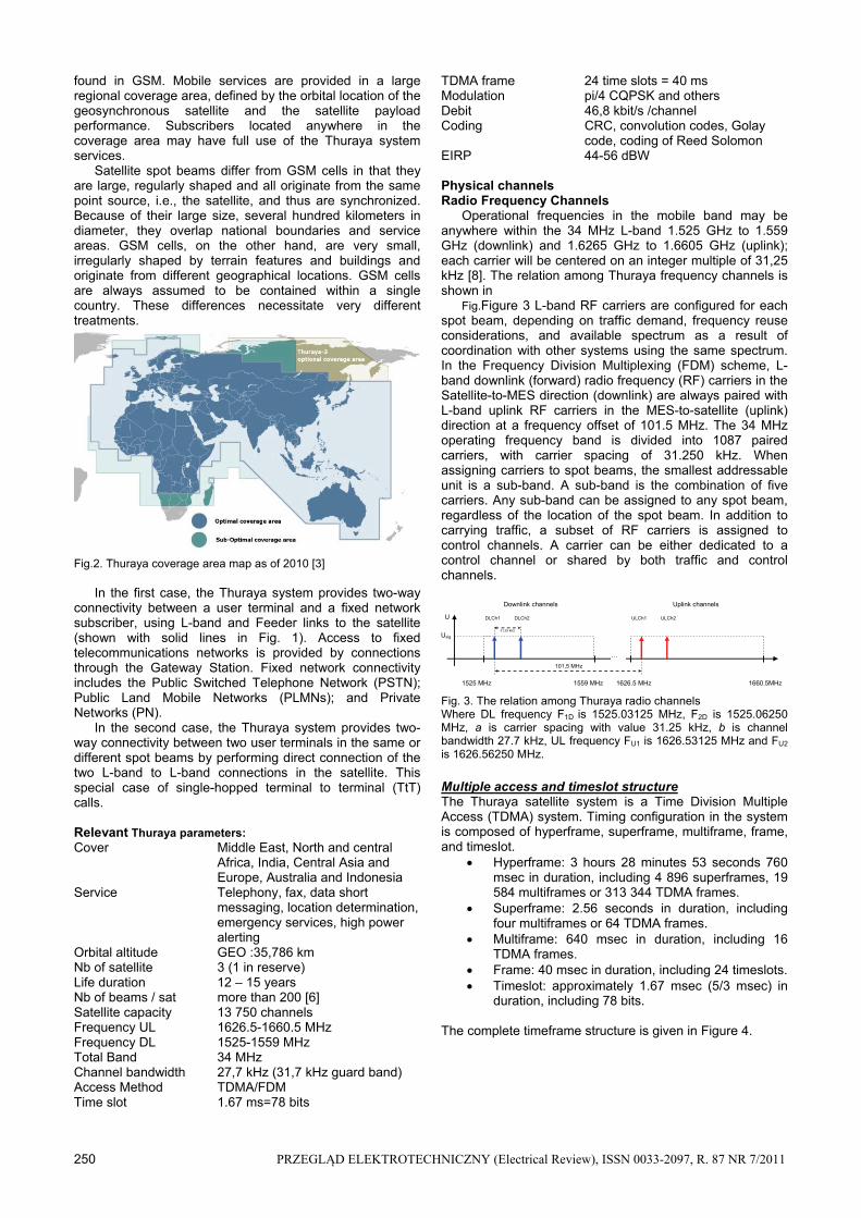
Operational frequencies in the mobile band may be anywhere within the 34 MHz L-band 1.525 GHz to 1.559 GHz (downlink) and 1.6265 GHz to 1.6605 GHz (uplink); each carrier will be centered on an integer multiple of 31,25 kHz [8]. The relation among Thuraya frequency channels is shown in
Fig.Figure 3 L-band RF carriers are configured for each spot beam, depending on traffic demand, frequency reuse considerations, and available spectrum as a result of coordination with other systems using the same spectrum. In the Frequency Division Multiplexing (FDM) scheme, L-band downlink (forward) radio frequency (RF) carriers in the Satellite-to-MES direction (downlink) are always paired with L-band uplink RF carriers in the MES-to-satellite (uplink) direction at a frequency offset of 101.5 MHz. The 34 MHz operating frequency band is divided into 1087 paired carriers, with carrier spacing of 31.250 kHz. When assigning carriers to spot beams, the smallest addressable unit is a sub-band. A sub-band is the combination of five carriers. Any sub-band can be assigned to any spot beam, regardless of the location of the spot beam. In addition to carrying traffic, a subset of RF carriers is assigned to control channels. A carrier can be either dedicated to a control channel or shared by both traffic and control channels.
…
1525 MHz 1559 MHz 1626.5 MHz 1660.5MHz
U DLCh1
Usig
Downlink channels Uplink channels
101,5 MHz
31,25 kHz
DLCh2 ULCh1 ULCh2
Fig. 3. The relation among Thuraya radio channels Where DL frequency F1D is 1525.03125 MHz, F2D is 1525.06250 MHz, a is carrier spacing with value 31.25 kHz, b is channel bandwidth 27.7 kHz, UL frequency FU1 is 1626.53125 MHz and FU2 is 1626.56250 MHz.
Multiple access and timeslot structure The Thuraya satellite system is a Time Division Multiple Access (TDMA) system. Timing configuration in the system is composed of hyperframe, superframe, multiframe, frame, and timeslot.
Hyperframe: 3 hours 28 minutes 53 seconds 760 msec in duration, including 4 896 superframes, 19 584 multiframes or 313 344 TDMA frames.
Superframe: 2.56 seconds in duration, including four multiframes or 64 TDMA frames.
Multiframe: 640 msec in duration, including 16 TDMA frames.
Frame: 40 msec in duration, including 24 timeslots. Timeslot: approximately 1.67 msec (5/3 msec) in
duration, including 78 bits. The complete timeframe structure is given in Figure 4.

PRZEGLĄD ELEKTROTECHNICZNY (Electrical Review), ISSN 0033-2097, R. 87 NR 7/2011 251
Fig. 4. Timeframe and timeslot structure [5, 7]
At the satellite, the TDMA frames on all of the radio frequencies in the downlink of each spot beam will be aligned. The same principle is also applied to uplink. At the MES, the start of a TDMA frame on the uplink is delayed by a variable amount from the start of the TDMA frame on the downlink. This delay is variable to allow for signal propagation delay. A physical channel which uses time division multiplexing and it is defined as a sequence of timeslots on a single Radio Frequency (RF) channel. The transmissions within these timeslots are known as bursts. Bursts
A burst is a single unit of transmission on the radio path defined in terms of RF channel, RF power profile and modulation symbols. Bursts are sent in a defined time and frequency window where the time window is defined by a range of contiguous timeslot numbers and the frequency window are defined by the carrier number. Therefore, a burst represents the physical content of one or more contiguous timeslots. The fundamental unit of burst timing is the half-symbol period. A timeslot consists of 78 half-symbol periods, each of 5/234 ms duration. A particular half-symbol period within a burst is referenced by a half-symbol number (HSN), with the first half-symbol period numbered 0. In the following clauses, the transmission timing of a burst is defined in terms of half-symbol numbers. The half symbol with the lowest half-symbol number is transmitted first. Different types of bursts exist in the system. One characteristic of a burst is its useful duration. The useful duration of a burst is defined as beginning with HSN5. The present document defines bursts with useful durations of 146, 224, 458, 614 and 692 half-symbol periods, based on total durations of 2, 3, 6, 8 and 9 timeslots. The period between the useful durations of successive bursts is termed the guard period. Each burst has a guard period with duration of five half-symbol periods before its useful duration and a similar guard period with duration of five half-symbol periods after its useful duration, which has the effect of centring a burst's useful duration within its timeslot(s). Many bursts contain a pattern of bits known as a unique word pattern, used to resolve phase ambiguities inherent in the modulation. In conjunction with Thuraya system several types of bursts are known: BACH burst, BCCH burst, CICH burst, DC2 burst, DC6 burst, DKABs bursts, FCCH burst, NT3 burst - NT3 burst for encoded speech and NT3 burst for FACCH, NT6 burst, NT9 burst, RACH burst and SDCCH burst. More information about the bursts is in [7]. In comparison of other satellite communication systems such as Inmarsat, the Thuraya system does not use special frequency channels for transmitting of service information. This information is transmitted in frequency channels of particular spot beam together with user data (voice or data).
To distinguish whether the user terminal or service data are transmitted, the data stream is arranged in logical channels. Logical channels
The logical channels associated with the Thuraya may either be a Traffic Channel (TCH) or a Control channel. TCHs are intended to carry encoded speech or user data. These are all bidirectional channels. TCH3: This channel carries normal speech and has a
gross information rate of 5.2 kbps, it takes 3 contiguous timeslots.
TCH6: This channel carries 2.4 kbps and 4.8 kbps user data and has a gross transmission rate of 10.75 kbps, it takes 6 contiguous timeslots.
TCH9: This channel carries 2.4 kbps, 4.8 kbps, and 9.6 kbps user data and has a gross transmission rate of 16.45 kbps, it takes 9 contiguous timeslots. The control channels are intended to carry signalling or
synchronization data. There are three different categories of control channels: a) Broadcast channel is a downlink (forward) only channel
and consists of the following: Frequency Correction CHannel (FCCH), GPS Broadcast Control CHannel (GBCH), Broadcast Control CHannel (BCCH), Cell Broadcast CHannel (CBCH).
b) Common Control CHannel (CCCH) consists of the following: Paging CHannel (PCH), Random Access CHannel (RACH), Access Grant CHannel (AGCH), Basic Alerting CHannel (BACH), Common Idle CHannel (CICH).
c) Dedicated Control CHannel (DCCH) is a channel resource that is dedicated for MES. They are all bidirectional except for the TACCH. The SACCH3 channel is a logical channel with the same physical burst structure as the FACCH3.
d) Slow TCH6-Associated Control CHannel (SACCH6): Slow TCH9-Associated Control CHannel (SACCH9), Fast TCH3-Associated Control CHannel (FACCH3), Fast TCH6-Associated Control CHannel (FACCH6), Fast TCH9 Associated Control CHannel (FACCH9), Standalone Dedicated Control CHannel (SDCCH), Terminal-to-Terminal (TtT) Associated Control CHannel (TACCH), Power control subchannel.
Time-domain signal description Physical channels The Air Interface allows multiple physical channels to share the same radio-frequency channel of a given spot beam using a TDMA scheme. Therefore, each physical channel is characterized by a sequence of timeslots on a radio-frequency channel. Once a physical channel has been allocated timeslots in a TDMA frame, it maintains the same timeslot numbers (relative to the start of the TDMA frame) in all subsequent TDMA frames, for the duration of the physical channel allocation. The uplink and downlink timeslot numbers assigned to a physical channel need not be same. Uplink and downlink physical channel timeslot assignments can cross TDMA frame boundaries. Logical channels The Air Interface also allows for the possibility, in specified cases, of multiple logical channels sharing a physical channel. This may be done by partitioning a physical channel's timeslots both by timeslot number relative to the start of the TDMA frame and by TDMA frame sequence. Therefore, characterization of a logical channel requires the definition of a frame sequence in addition to a sequence of timeslots on a physical channel.

252 PRZEGLĄD ELEKTROTECHNICZNY (Electrical Review), ISSN 0033-2097, R. 87 NR 7/2011
Physical channel (PC) types and names By convention, the distinguishing characteristics of
physical channel types are captured in their names. Physical channel names start with the letters PC (physical channel) followed by the number of contiguous timeslots used per TDMA frame. In the case of a unidirectional channel, a suffix is added designating the channel's direction, "u" for uplink or "d" for downlink. Six types of physical channels are used, as follows: PC2d, a physical channel with a length of two timeslots
for downlink only; PC6d, a physical channel with a length of six timeslots
for use only by the downlink; PC12u, a physical channel with a length of 12 timeslots
for use only by the uplink; PC3, a physical channel with a length of three timeslots; PC6, a physical channel with a length of six timeslots; PC9, a physical channel with a length of nine timeslots. There are only a few permitted ways in which logical channels can populate physical channels, as described in [7]. Experiments
The experimental evaluation of Thuraya system’s detection has been conducted in a basic test, shown in Figure 5. Its structure can be divided into two essential systems. First part consists of UL monitoring subsystem which is dedicated for UL frequency band monitoring and for time and frequency analysis.
Fig. 5. Structure of experimental test bed
Essential parts of that system are high performance oscilloscope Agilent Infinitum 80804B with attached external satellite antenna. User terminal consists of Thuraya mobile station SO-2510 plugged into docking station and Thuraya external satellite antenna. Second part of test bed is dedicated for DL channels monitoring. It consists of spectrum analyzer Anritsu MS2711D used for downlink monitoring. Overall arrangement of test bed enabled primary measurements in indoor environment.
Initially, the frequency spectrum analysis of both DL and UL frequency band was conducted. Due to the hardware limitations, it wasn’t possible to capture and analyze data in DL channel and subsequently to analyze time frames composition during the initialization, spot beam selection and sending of system information. For this reason, primary goal was focused on analysis of DL channels in frequency domain and UL channels in both frequency and time domain.
Signal characteristics First experiment was focused on verification of Thuraya
frequency plan pattern in particular spot beam and also confirmation of relationship between UL and DL channel frequencies. Every spot beam has predetermined frequency sub-band which is a combination of five carriers. Any sub-band can be assigned to any spot beam, regardless of the location of the spot beam. In order to prove this hypothesis the DL frequency band has been monitored by spectral analyzer during several experimental measurements. The initial condition for this experiment was that any Thuraya mobile terminals were switched on. The results of UL band frequency spectrum measurement are shown in Figure 6.
It indicates that only one UL channel is allocated for particular spot beam whether the mobile terminals are active or not. The measured frequency of active UL channel is 1634.843750MHz. The several measurements were conducted in different time intervals, with the aim to obtain information whether frequency of channels are updated or not. In spite of the fact that other UL channels haven’t been intercepted, it is most likely that another L-band RF carriers will be configured for each spot beam, depending on traffic demand, frequency reuse considerations, and available spectrum as a result of coordination with other systems using the same spectrum. Signal characteristics
First experiment was focused on verification of Thuraya frequency plan pattern in particular spot beam and also confirmation of relationship between UL and DL channel frequencies. Every spot beam has predetermined frequency sub-band which is a combination of five carriers. Any sub-band can be assigned to any spot beam, regardless of the location of the spot beam. In order to prove this hypothesis the DL frequency band has been monitored by spectral analyzer during several experimental measurements. The initial condition for this experiment was that any Thuraya mobile terminals were switched on. Base on captured data via oscilloscope Agilent Infinitum 80804B, the spectrogram of UL frequency band was computed in Matlab. The results are shown in Fig.6.
Fig. 6. Spectrogram of Thuraya ULCh267
It indicates that only one UL channel is allocated for particular spot beam whether the mobile terminals are active or not. The measured frequency of active UL channel is 1634.843750MHz. The several measurements were conducted in different time intervals, with the aim to obtain information whether frequency of channels are updated or

PRZEGLĄD ELEKTROTECHNICZNY (Electrical Review), ISSN 0033-2097, R. 87 NR 7/2011 253
not. In spite of the fact that other UL channels were not intercepted, it is most likely that another L-band RF carriers will be configured for each spot beam, depending on traffic demand, frequency reuse considerations, and available spectrum as a result of coordination with other systems using the same spectrum.
Subsequent experiments were focused on the verification of relationship between UL and DL channel frequencies. In the pattern of frequency plan, L-band DL and UL channels have frequency offset of 101.5MHz. With the knowledge of the UL channel frequency the DL channel frequency can be determined by simple formula. The relation among Thuraya channel frequencies can be found in Fig.3. Knowing the frequency of UL RF channel in particular spot beam, which is in our case fUL=1634.843750MHz called ULCh267, we focus spectral analysis in order to determine the DL channel frequency. The computed central frequency of DL RF channel is fDL= 1533.34375MHz. The screenshot of spectral analyzer displays (Figure 7) frequency spectrum of Thuraya DL channel, where measured central frequency of channel is fDL=1533,343MHz.
Fig. 7 Spectrum of DL frequency band
This channel is called as DLCh267 and has level -113dBm. Figure 7 also shows the spectrum of adjacent signal which is Inmarsat DL channel at the central frequency 1533.1MHz with bandwidth 200kHz (level -122dBm). This fact confirms the UL and DL channel composition which was analyzed. UL signal analysis
The purpose of these experiments was to analyze UL channel in time domain during the call initialization, to determine crucial time intervals and analyze the type of the bursts which are transmitted in UL channel during call initialization. As initiator of call, two types of user terminals were used.
First was GSM mobile phone and second Thuraya mobile terminal. The second Thuraya mobile terminal was used as answer user station. The measured time series of UL Thuraya bursts are shown in Fig. 8. First pulse is followed by two series of 40 pulses. Several characteristic time periods can be recognized. The time duration of pulse 1 is 14.83750ms (pulse 1). Having information how logical channels are organized within physical channels, there are several logical channels which can be transmitted in UL direction. One of them is Random Access Channel (RACH) which is one of logical channels dedicated for call initialization. It is used to request a Standalone Dedicated Control Channel (SDCCH) or Traffic Channel (TCH) allocation. The RACH comprises of 9 time slots (every time slot has 5/3ms) which is totally 15ms long time period. With respecting of the measurement fault, particular time interval
can be identified as RACH logical channel which is part of the PC12u physical channel, see [7].
Fig. 8. Time series of the Thuraya UL bursts
The next series of pulses is followed after time interval 0.789016s. This time interval is approximately 20 time frames long (every time frame has duration 40ms). From analysis it is also implied that SDCCH and TCH logical channel can be sent within DL channel (DLCh267). The exact composition of the DL logical channels was not possible to determine due to the technical restriction of experimental test bed.
The time pulse 2 has duration 4.8575ms, which are approximately 3 time slots. Logical channel TCH3 (Traffic channel) and FACCH3 (Fast associated control channel) [7] can take 3 time slots, both in UL and DL direction. TCH3 and FACCH3 logical channels can be transmitted within these signal time series as a part of permitted channel configuration PC3. To determine either TCH3 or FACCH3 logical channel is transmitted can be identified by analysis of modulation scheme. Traffic channel TCH3 uses /4 CQPSK modulation and FACCH3 uses /4 CBPSK modulation. Furthermore, spectral analysis of every pulse determines which channel frequency was used for its transmitting. For these particular measurements, UL channel frequency is 1634.875MHz (called as ULCh268), which has 31.25kHz higher value than ULCh267. Frequency of DL channel is determined by formula fDL=fUL-101.5MHz. In this case the frequency of DL channel is 1533.375MHz (called as DLCh268) which was also confirmed by practical measurement of DL frequency band. The spectrum of DL frequency band with DLCh267 and DLCh268 is shown in Figure 9.
Fig. 9. Spectrum of downlink frequency band with DLCh267 and DLCh268

254 PRZEGLĄD ELEKTROTECHNICZNY (Electrical Review), ISSN 0033-2097, R. 87 NR 7/2011
Practical measurement showed that Thuraya system allocates during call initialization two channels for single connection between two mobile terminals. As was mentioned previously, channel ULCh267 is used for sending of channel allocation (RACH logical channel). As soon as the Thuraya control station allocates channel where the user traffic will be transmitted, the mobile station tune itself to the adjacent channel (in this case ULCh268). Subsequently, following bursts are sent via ULCh268. The time period between pulses 3 and 2 is 35.148ms. Series of 40 pulses (pulse 2) is followed by another series of 40 pulses.
The second series of experiments was focused on call initialization time series analysis between two Thuraya mobile terminals. The UL time series of two Thuraya mobile terminals are shown in Fig.10.
The process of transmission and time series dependences of two Thuraya mobile terminals during call initialization are same as was described above. The first Thuraya terminal (pulse 4) initiates a call. As soon as Thuraya control station determines the channel frequency for its communication the same procedure is conducted for called Thuraya terminal (pulse 5). The time difference between pulse 4 and 5 (two RACH logical channels) is 0.59999 sec.
Both Thuraya mobile terminals use same channel Ch268 which is 1533.375MHz for DL frequency band and 1634.875MHz for UL frequency band. The fact that both Thuraya mobile stations use same UL and DL channel frequencies means that time series of pulses are transmitted in time multiplex within particular channels.
Fig. 10. Time series of two Thuraya mobile terminals signals Conclusions
The paper describes the experiments during which the time, frequency and time-frequency analysis of Thuraya signal was conducted. The results show that it is possible to identify structure of time series during call initialization, frequency channel pattern in UL and DL frequency band.
Spectral analysis showed that system determined one frequency channel for particular spot beam for call initialization and sending of the service data during authorization of the user terminal. Other frequency channels are allocated base on user terminal requirements, where additional service data and user data are transmitted. Practical results show that Thuraya system kept the same frequency pattern in spot beam during experiments. Experiments showed that for successful and timely blocking of incoming call that can be used as IED trigger from the Thuraya user terminal it is necessary to keep situation awareness about UL and DL frequency band in order to identify the time interval (RACH) during which the connection initialization between two user terminals starts.
REFERENCES [1] Bruce R. Elbert: The Satellite Communication Applications
Handbook, Artech House, 2004, ISBN: 1-58053-490-2 [2] Louis J. IPPOLITO, Jr.: Satellite Communications Systems
Engineering. Atmospheric Effects, Satellite Link Design and System Performance. 2008 John Wiley & Sons Ltd, ISBN 978-0-470-72527-6,
[3] Thuraya coverage area map as of 2010 http://www.satellitephonefaq.com/thuraya/network/coverage-2008/
[4] GMR-1 01.202 (ETSI TS 101 376-1-3): "GEO-Mobile Radio Interface Specifications; Part 1: General specifications; Sub-part 3: General System Description".
[5] GMR-1 05.001 (ETSI TS 101 376-5-1): "GEO-Mobile Radio Interface Specifications; Part 5: Radio interface physical layer specifications; Sub-part 1: Physical layer on the Radio Path; General description".
[6] Complete System for Mobile Communications http://www.boeing.com/defense-space/space/bss/factsheets/geomobile/thuraya2_3/thuraya2_3.html
[7] GMR-1 05.002 (ETSI TS 101 376-5-2): "GEO-Mobile Radio Interface Specifications; Part 5: Radio interface physical layer specifications; Sub-part 2: Multiplexing and Multiple Access; Stage 2 Service Description"
[8] GMR-1 05.005 (ETSI TS 101 376-5-5): "GEO-Mobile Radio Interface Specifications; Part 5: Radio interface physical layer specifications; Sub-part 5: Radio Transmission and Reception".
[9] GMR-1 05.008 (ETSI TS 101 376-5-6): "GEO-Mobile Radio Interface Specifications; Part 5: Radio interface physical layer specifications; Sub-part 6: Radio Subsystem Link Control".
[10] GMR-1 05.010 (ETSI TS 101 376-5-7): "GEO-Mobile Radio Interface Specifications; Part 5: Radio interface physical layer specifications; Sub-part 7: Radio Subsystem Synchronization".
Authors: Ing. Roman BERESIK PhD. E-mail: [email protected] Ing. Milos SOTAK PhD, E-mail: [email protected] Assoc. Prof. Ing. Frantisek NEBUS PhD. E-mail: [email protected] Assoc. Prof. Ing. Jozef PUTTERA PhD, E-mail: [email protected] Armed Forces Academy, Department of Electronics, Demanova 393, 031 06 Liptovsky Mikulas 6, Slovakia,