SAR-based vibrometry using the fractional Fourier...
11
1 [email protected]; 2 [email protected]; 3 [email protected]; phone 1 505 507-6655; 4 [email protected]; 5 [email protected]; phone 1 505 277-2711; 6 [email protected]; 7 [email protected]; phone 1 858 762-6751; fax 1 858 762-5178; 8 [email protected]; phone 1 505 845-7632; fax 1 505 844-7886; 9 [email protected]; phone 1 505 845-8165; fax 505 845-5491; 10 [email protected]; phone 1 505 277-3458; 11 [email protected]; phone 1 505 277-1611; 12 [email protected]; phone 1 505 272-7095; fax 1 505 272-7801; SAR-based vibrometry using the fractional Fourier transform Justin B. Campbell 1 , Qi Wang 2 , Jelili Ade-Bello 3 , Humberto Caudana 4 , Nicole B. Trujillo 5 , Ishwor Bhatta 6 , Ralf Dunkel 7 , Thomas Atwood 8 , Armin Doerry 9 , Walter H. Gerstle 10 , Balu Santhanam 11 , Majeed M. Hayat 12 The Center for High Technology Materials and the Electrical and Computer Engineering Department, The University of New Mexico, 1313 Goddard SE Albuquerque, NM, USA 87106; Sandia National Laboratories, 1515 Eubank SE Albuquerque, NM 87123 USA; General Atomics Aeronautical Systems, Inc. 14200 Kirkham Way, Poway, CA 92121 USA ABSTRACT A fundamental assumption when applying Synthetic Aperture Radar (SAR) to a ground scene is that all targets are motionless. If a target is not stationary, but instead vibrating in the scene, it will introduce a non-stationary phase modulation, termed the micro-Doppler effect, into the returned SAR signals. Previously, the authors proposed a pseudo- subspace method, a modification to the Discrete Fractional Fourier Transform (DFRFT), which demonstrated success for estimating the instantaneous accelerations of vibrating objects. However, this method may not yield reliable results when clutter in the SAR image is strong. Simulations and experimental results have shown that the DFRFT method can yield reliable results when the signal-to-clutter ratio (SCR) > 8 dB. Here, we provide the capability to determine a target's frequency and amplitude in a low SCR environment by presenting two methods that can perform vibration estimations when SCR < 3 dB. The first method is a variation and continuation of the subspace approach proposed previously in conjunction with the DFRFT. In the second method, we employ the dual-beam SAR collection architecture combined with the extended Kalman filter (EKF) to extract information from the returned SAR signals about the vibrating target. We also show the potential for extending this SAR-based capability to remotely detect and classify objects housed inside buildings or other cover based on knowing the location of vibrations as well as the vibration histories of the vibrating structures that house the vibrating objects. Keywords: Vibration estimation; discrete fractional Fourier transform; extended Kalman filter; Fourier transform; subspace method; synthetic aperture radar; signal-to-clutter ratio 1. INTRODUCTION Synthetic Aperture Radar (SAR) is a remote-sensing technique, typically performed with aircraft or spacecraft, which has advanced significantly over the past few decades [8]-[10]. Capable of high-resolution terrain images in all weather conditions, SAR delivers complementary and possibly otherwise unattainable information in a plethora of remote sensing applications. SAR transmits electromagnetic (EM) radiation to ground scenes and measures the returned signal, which contains information about the EM reflectivity of all objects. This active illumination feature facilitates the identification and classification of ground objects.
Transcript of SAR-based vibrometry using the fractional Fourier...

[email protected]; [email protected]; [email protected]; phone 1 505 507-6655; [email protected]; [email protected]; phone 1 505 277-2711; [email protected]; [email protected]; phone 1 858 762-6751; fax 1 858 762-5178; [email protected]; phone 1 505 845-7632; fax 1 505 844-7886; [email protected]; phone 1 505 845-8165; fax 505 845-5491; [email protected]; phone 1 505 277-3458; [email protected]; phone 1 505 277-1611; [email protected]; phone 1 505 272-7095; fax 1 505 272-7801;
SAR-based vibrometry using the fractional Fourier transform Justin B. Campbell1, Qi Wang2, Jelili Ade-Bello3, Humberto Caudana4, Nicole B. Trujillo5, Ishwor
Bhatta6, Ralf Dunkel7, Thomas Atwood8, Armin Doerry9, Walter H. Gerstle10, Balu Santhanam11,
Majeed M. Hayat12
The Center for High Technology Materials and the Electrical and Computer Engineering
Department, The University of New Mexico, 1313 Goddard SE Albuquerque, NM, USA 87106;
Sandia National Laboratories, 1515 Eubank SE Albuquerque, NM 87123 USA; General Atomics
Aeronautical Systems, Inc. 14200 Kirkham Way, Poway, CA 92121 USA
ABSTRACT
A fundamental assumption when applying Synthetic Aperture Radar (SAR) to a ground scene is that all targets are
motionless. If a target is not stationary, but instead vibrating in the scene, it will introduce a non-stationary phase
modulation, termed the micro-Doppler effect, into the returned SAR signals. Previously, the authors proposed a pseudo-
subspace method, a modification to the Discrete Fractional Fourier Transform (DFRFT), which demonstrated success for
estimating the instantaneous accelerations of vibrating objects. However, this method may not yield reliable results when
clutter in the SAR image is strong. Simulations and experimental results have shown that the DFRFT method can yield
reliable results when the signal-to-clutter ratio (SCR) > 8 dB. Here, we provide the capability to determine a target's
frequency and amplitude in a low SCR environment by presenting two methods that can perform vibration estimations
when SCR < 3 dB. The first method is a variation and continuation of the subspace approach proposed previously in
conjunction with the DFRFT. In the second method, we employ the dual-beam SAR collection architecture combined
with the extended Kalman filter (EKF) to extract information from the returned SAR signals about the vibrating target.
We also show the potential for extending this SAR-based capability to remotely detect and classify objects housed inside
buildings or other cover based on knowing the location of vibrations as well as the vibration histories of the
vibrating structures that house the vibrating objects.
Keywords: Vibration estimation; discrete fractional Fourier transform; extended Kalman filter; Fourier transform;
subspace method; synthetic aperture radar; signal-to-clutter ratio
1. INTRODUCTION
Synthetic Aperture Radar (SAR) is a remote-sensing technique, typically performed with aircraft or spacecraft, which
has advanced significantly over the past few decades [8]-[10]. Capable of high-resolution terrain images in all weather
conditions, SAR delivers complementary and possibly otherwise unattainable information in a plethora of remote
sensing applications. SAR transmits electromagnetic (EM) radiation to ground scenes and measures the returned signal,
which contains information about the EM reflectivity of all objects. This active illumination feature facilitates the
identification and classification of ground objects.

In its most basic form, SAR artificially creates a significantly larger aperture while traversing a ground scene. While
traversing the ground scene, the system periodically measures the EM reflectivity on each object. SAR Processing, i.e.,
combining the data at each collection location, provides a high-resolution image. The success of this collection technique
depends heavily on the assumption that all targets in the ground scene are stationary during collection. The returned SAR
signals from static targets (after pre-processing) are all stationary. More specifically, the returned SAR signals are the
superposition of pure sinusoids. Conventional SAR image formation methods, which are based on the Fourier transform
(FT), are able to focus the targets on their correct positions by “compressing'' the returned SAR signals to impulses
located at the frequencies that are linearly related to the target's locations. However, since we assume all the targets are
static during the data-collection process, SAR imagery is sensitive to any low-level target vibrations [11]-[18].
Specifically, target vibrations cause SAR images to contain localized artifacts, or “ghost targets,'' in the azimuthal (cross-
range) direction. This is because the vibrations introduce non-stationary phase modulation, termed the micro-Doppler
effect [15], into the returned SAR signals.
While non-stationary targets degrade the resolution and create artifacts in the image, it could be of great benefit to have a
reliable method to determine the target's vibration characteristics remotely: specifically frequency and amplitude from
the non-stationary phase modulated return signals. This capability could provide remote monitoring for machinery,
unique target identifiers in defense applications, or extract activity information about concealed structures. Previously,
the authors proposed the discrete fractional Fourier transform (DFRFT) [1] demonstrated success for estimating the
instantaneous accelerations of vibrating objects [2]–[5]. However, in some cases this method may not yield reliable
results when clutter (static targets) in the SAR image is strong. Simulations and experimental results show that the
DFRFT-based vibration estimation method can yield reliable results for the signal-to-clutter ratio (SCR) > 8 dB [6].
Although the SCR requirement of the DFRFT-based method is easily satisfied by appropriate SAR system design
choices, it is still of great benefit to have the capability of estimating target vibrations in low SCR scenarios, i.e., 3 dB or
lower. In this paper, we present two methods to handle low SCR scenarios. The first is clutter suppression using rank-
reduction and subspace methods. We incorporated these into the already existing DFRFT based method, which enhanced
the performance in low SCR scenarios [1]. The second method depends on an entirely different collection technique, the
along-track dual-beam SAR, also known as the monopulse (squinted) phase beam SAR. The collection geometry of
dual-beam provides a means to remove all the clutter from the signal, since the clutter is common to both beams. We
then apply extended Kalman filter (EKF) to determine the vibration characteristics.
2. RANK-REDUCTION AND SUBSPACE METHODS
For nonstationary signals, the continuous-time fractional Fourier transform is an incredibly powerful and extremely
successful time–frequency analysis technique. This transform is used in a variety of applications including both optics
and signal processing [33]. Earlier work by the authors showed the estimation of common ground-target vibrations can
be transformed into estimating chirp parameters of the returned signal in properly sized subapertures [1].
Vibration frequency estimation involves the application of the DFRFT directly to the signal of interest (SoI).
Subsequently, using the peak-to-parameter mapping, we find the peak coordinate location, translate these peak
coordinates into a center frequency, and estimate the chirp rate. This direct approach works well when both the SNR and
SCR are high. However, in the presence of significant clutter, i.e., strong reflections by static targets located near the
vibrating object, estimating the peak coordinates accurately becomes difficult. This difficulty is due to the manifestation
of significant side lobes in the DFRFT spectrum [31].
Continuing from a previously proposed subspace approach, we use the rank-reduction and subspace method in
conjunction with the DFRFT to perform vibration estimation in the presence of clutter. Prior application of subspace
methods, for vibration estimation applications, implemented the crosshair technique. We place the crosshairs on top of
the DFRFT peak. The vertical and horizontal slices of the DFRFT generated by the crosshairs are frequency variables.
These frequency variables are transformed into time-domain quantities using the inverse DFT. We use the transformed
slices as inputs into the various subspace methods. Ideally, the peak in the DFRFT spectrum will be a delta function,
resulting in the subspace signals being sinusoidal. However, in the DFRFT spectrum, we only get an approximation of
Gauss-Hermite functions in the form of DFT eigenvectors. Thus, the subspace signals will deviate from sinusoidal
signals as depicted in Figure 1. Prior work in [2], [3] did not include rank-reduction and filtering of the subspace signals

to remove clutter that manifests as high-frequency noise in the center-frequency and chirp-rate slices. Rank reduction
employs correlation matrices that use just the signal subspace, thereby rejecting a great portion of the noise and clutter
prevalent in the other subspaces [29]. Incorporating filtering and rank reduction is expected to reduce the effects of noise
and clutter significantly, and produce enhanced peaks in the vibration spectrum in comparison to direct application of the
DFRFT as depicted in Figure 2 and Figure 3.
In the following simulations, we consider a single vibrating target oscillating at 5 Hz with a 1 mm amplitude. As for the
received signal characteristics, we consider SNR = 30 dB and SCR = 5 dB. Using an initial sampling frequency of 3.216
MHz, we applied a down-sampler on the data to a sampling rate of 40 KHz. We model the reflectance of the clutter
pixels as a Gamma distribution. Figure 1 shows that simple binomial smoothing of these subspace slices reduces the
effects of clutter and noise in the signal. In the simulations shown in Fig. 2 we add the presence of clutter to demonstrate
our ability to isolate in the SoI due the presence of unwanted side lobes. Moreover, in Fig. 3 signal subspace methods,
such as the principle component Blackman-Tukey (PC-BT), enable more clutter suppression via rank reduction than
subspace methods such as the min-norm approach.
(a)
(b)
(c)
(d)
Figure 1. DFRFT center-frequency and chirp-rate subspace slices for a synthetic chirp depicting waveforms with clutter
manifesting as high-frequency noise. Simple binomial smoothing of these subspace slices reduces the effects of clutter and
noise in the signal.

(a) (b)
(c)
Figure 2. Direct DFRFT estimates from real data: (a) SAR image used in the experiment, (b) acceleration estimates for SNR
of 30 dB and SCR of 5 dB that are quite noisy, and (c) corresponding vibration spectrum depicting a peak at 2.5 Hz
corresponding to the vibration frequency in the presence of significant clutter manifested in the form of side lobes.
(a) (b)

(c)
Figure 3. Subspace estimates incorporating rank reduction on real data: (a) acceleration estimates for SNR = 30 dB and SCR
= 5 dB, depicting a clearer picture, (b) vibration spectra for the min-norm method, depicting a sharp null at 2.5 Hz that still
incorporates a lot of clutter in the form of side lobes, and (c) the principle component Blackman-Tukey (PC-BT) method,
depicting a significantly sharper peak at 2.5 Hz and reduced clutter.
3. ALONG-TRACK DUAL-BEAM SAR
Along-track dual beam SAR differs from conventional SAR in that it has two individual SAR antennas working
collectively in a single system. These two SAR antennas are orientated in the azimuth or cross-range direction. That is,
they are positioned one behind the other relative to the aircraft or spacecraft’s direction of travel [28]. Each antenna will
provide its own individual complex SAR image. Using these two separate images to make comparisons, we can detect
changes in the ground scene between the collection times. In particular, we are using the along-track dual beam SAR to
detect vibrations of objects.
The along-track dual-beam SAR system is extremely successful in a variety of ground moving target indication (GMTI)
applications [19]–[23]. These targets, however, usually have pure translation through the ground scene. Vibrating
structures, however, only oscillate around a fixed point. Nevertheless, using the along-track dual-beam SAR, we mount
two antennas at the same altitude, aligned in the direction of travel. Each individual antenna views the same ground
scene at the same viewing location. The only collection parameter that is different is the time at which each antenna
observes the ground scene. Therefore, the two antennas receive the same signals from clutter only with a known time
delay, 𝜏𝐵. However, each antenna will receive a slightly different signal from a vibrating target due to the time-varying
vibration displacements. By taking the difference of the signals collected by the two antennas, we can ideally remove the
clutter entirely and obtain a signal modulated by the vibration dynamics in a non-linear manner.
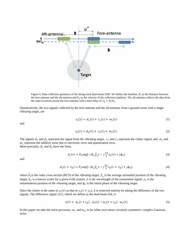
Figure 4. Data-collection geometry of the along-track dual-beam SAR. We define the baseline, 𝐵, as the distance between
the fore-antenna and the aft-antenna and 𝑉𝐴 as the velocity of the collection platform. The aft-antenna collects the data from
the same locations points the fore-antenna with a time delay of 𝜏𝐵 = 𝐵/𝑉𝐴.
Quantitatively, the two signals collected by the fore-antenna and the aft-antenna, from a ground scene with a single
vibrating target, are
𝑠1(𝜏) = 𝑑1(𝜏) + 𝑐1(𝜏) + 𝑤1(𝜏) (1)
and
𝑠2(𝜏) = 𝑑2(𝜏) + 𝑐2(𝜏) + 𝑤2(𝜏). (2)
The signals 𝑑1 and 𝑑2 represent the signal from the vibrating target, 𝑐1 and 𝑐2 represent the clutter signal, and 𝑤1 and
𝑤2 represent the additive noise due to electronic error and quantization error.
More precisely, 𝑑1 and 𝑑2 have the form,
𝑑1(𝜏) = 𝜎𝑣exp [−𝑗𝑘𝑦𝑦𝑣
𝜏 − 𝑗4𝜋
𝜆𝑥𝑣(𝜏) + 𝑗𝜙𝑣] (3)
and
𝑑2(𝜏 + 𝜏𝐵) = 𝜎𝑣exp [−𝑗𝑘𝑦𝑦𝑣
𝜏 − 𝑗4𝜋
𝜆𝑥𝑣(𝜏 + 𝜏𝐵) + 𝑗𝜙𝑣], (4)
where 𝜎𝑣is the radar cross section (RCS) of the vibrating target, 𝑦𝑣 is the average azimuthal position of the vibrating
target, 𝑘𝑦 is a known scalar for a given SAR system, 𝜆 is the wavelength of the transmitted signal, 𝑥𝑣 is the
instantaneous position of the vibrating target, and 𝜙𝑣 is the initial phase of the vibrating target.
Since the clutter is the same in 𝑠1(𝜏) as that in 𝑠2(𝜏 + 𝜏𝐵), it is removed entirely by taking the difference of the two
signals. The difference signal 𝑠(𝜏), which we define as the dual-beam SoI, is
𝑠(𝜏) = 𝑑2(𝜏 + 𝜏𝐵) - 𝑑1(𝜏) + 𝑤2(𝜏 + 𝜏𝐵) - 𝑤1(𝜏) (5)
In this paper we take the noise processes, 𝑤1 and 𝑤2, to be white zero-mean circularly symmetric complex Gaussian
noise.

Since 𝜏𝐵 is typically no more than a few milliseconds in most dual-beam SAR systems, this time is significantly shorter
than the vibrations of interest. This gives us the ability to make the following approximation
𝑥𝑣(𝜏 + 𝜏𝐵) ≈ 𝑥𝑣(𝜏) + 𝑉𝑣(𝜏)𝜏𝐵, (6)
where 𝑉𝑣(𝜏) is the instantaneous vibration velocity of the target. Using this approximation and some algebraic
manipulations, 𝑑(𝜏) is written as
𝑑(𝜏) = 𝑑2(𝜏 + 𝜏𝐵) − 𝑑1(𝜏) = 2𝜎𝑣(τ)sin (
2𝜋𝜏𝐵𝑉𝑣(𝜏)
𝜆)exp [−𝑗
2𝜋
𝜆(2𝑥𝑣(𝜏) + 𝜏𝐵𝑉𝑣(𝜏)) − 𝑗
𝜋
2)] (7)
where
𝜎𝑣(τ) = 𝜎𝑣exp [−𝑗𝑘𝑦�̅�𝑣𝜏 + 𝑗𝜙𝑣]. (8)
Now, since the SoI, given by
𝑠(𝜏) = 𝑑(𝜏) + 𝑤2(𝜏 + 𝜏𝐵) - 𝑤1(𝜏), (9)
contains information about the instantaneous position and velocity, 𝑥𝑣(𝜏) and 𝑉𝑣(𝜏), of the vibrating target, the problem
of estimating the vibration dynamics is a standard non-stationary signal estimation problem [24]. This creates the ability
to use recursive estimation methods such as the Kalman filter [25]. However, the nonlinear nature of the observed signal
model prevents us from directly applying the Kalman filter to the dual-beam SoI for vibration estimation. Nevertheless,
we can first linearize the observed signal model at each estimate and then apply the Kalman filter. This method is
commonly referred to as the extended Kalman filter (EKF). Although the EKF is generally sub-optimal for nonlinear
estimation problems, it is widely used and it has been considered the de facto standard in nonlinear state estimation for
well-defined transition models [25], [26]. We defer the full description of the EKF in this model to a later publication.
However, listed below we show certain results using simulated data.
We simulated an airborne spotlight-mode dual-antenna SAR operating in the 𝐾𝑢 band to validate the proposed method.
A dual-beam collection geometry has an equivalent transformation to that of two distinct antennas. Thus, all
mathematical equations formulated above are applicable to this collection technique. We note that General Atomics’
dual-beam SAR system is an amplitude monopulse (squinted) beam system, pointed left and right, in the azimuth
direction, relative to the bore center. Table 1 lists the key system parameters associated with the simulation.
Table 1: SAR System Parameters Used in the Simulation
PARAMETER QUANTITY
pixel dimension 0.33 𝑥 .33 𝑚2
nominal slant-range 10000 𝑚
nominal grazing angle 10°
carrier frequency 𝑓𝑐 = 16 𝐺𝐻𝑧
baseline 𝐵 = 10 𝑚
sent pulse bandwidth 𝑓0 = 500 𝑀𝐻𝑧
plane velocity 𝑉 = 250 𝑚/𝑠
pulse-repetition frequency 900 𝐻𝑧
Listed below are the preliminary results of applying the EKF to a dual-beam SAR system.

Figure 5. Simulated SAR image containing a vibrating target in the middle with SCR = 3 dB. The vibration magnitude and
frequency are 1mm and 5 Hz, respectively.
Figure 6. The magnitude of the dual-beam SoI with SNR = 13 dB. The vibration magnitude and frequency are 1 mm and 5
Hz, respectively.
.

Figure 7. The spectrum of the magnitude of the dual-beam SoI with SNR = 13 dB. The vibration magnitude and frequency
are 1 mm and 5 Hz, respectively.
Figure 8. Estimated and true vibration velocities using the EKF-based method with SNR = 13 dB. The vibration
magnitude and frequency are 1mm and 5 Hz, respectively.
4. FUTURE ACTIVITIES
Vibration signatures from active structures, such as buildings that contain certain machinery or generators of
interest, combustion-based engines/vehicles and operational underground facilities, can bear vital characteristic
signatures about these structures. We can correlate many of these signatures to nuclear proliferation activities.
Therefore, the ability for us to reliably detect vibration signals remotely can greatly benefit proliferation detection
missions at particular sites of interest. Combining the vibration characteristics with an overhead SAR image, we
anticipate the use of multi-dimensional recognition analysis techniques to provide warnings of the presence of
suspicious operational machinery concealed within buildings and other types of cover. Figure 9 shows the vibration
histories, namely the instantaneous frequency as a function of time, of three types of common engines measured by
accelerometers: a small diesel engine, a large diesel engine, and a turbine engine. It is worth noting the distinction in
the frequencies and their separations present in each type of engine, as well as the transient behavior observed as we
alter the engine speeds. It is plausible to think we can extract many features from the vibration histories, both in the
steady state and transient modes of operation. A natural question to ask is whether we can sense these vibrations
remotely once they are concealed inside buildings, and if so can we identify types of machinery from the
information sensed from the buildings.
Figure 9. Instantaneous frequency histories of three engines at 50% throttle measured by accelerometers: (a) small diesel,
(b) large diesel, and (c) turbine. Note that the frequencies as well as the variations within them vary from engine to engine.

5. ACKNOWLEDGMENTS
The authors would like to thank General Atomics – Aeronautical Systems, Incorporated (San Diego, CA) for making the
Lynx system available for this project. This work was supported by the United States Department of Energy (Award No.
DE-FG52-08NA28782 and DE-NA0002494).
REFERENCES
[1] Q. Wang, B. Santhanam, M. Pepin, T. Atwood, and M. M. Hayat, “SAR vibrometry using a pseudo-subspace
approach based on the discrete fractional Fourier transform,” in Proc. SPIE, SPIE Defense, Security and Sensing
Symposium, Orlando, FL, Apr. 2011.
[2] Q. Wang, M. Pepin, R. J. Beach, R. Dunkel, T. Atwood, B. Santhanam, W. Gerstle, and M. M. Hayat, “SAR-based
vibration estimation using the discrete fractional Fourier transform,” IEEE trans. Geoscience and Remote Sensing, vol.
PP, no. 99, 2012.
[3] Q. Wang, M. Pepin, R. J. Beach, R. Dunkel, T. Atwood, A. W. Doerry, B. Santhanam, W. Gerstle, and M. M.
Hayat,“Demonstration of target vibration estimation in synthetic aperture radar imagery,” in The 2011 IEEE
InternationalGeoscience and Remote Sensing Symposium (IGARSS 2011), Vancouver, Canada, Aug. 2011.
[4] Q. Wang, M. Pepin, B. Santhanam, T. Atwood, and M. M. Hayat, “SAR-based vibration retrieval using the fractional
Fourier transform in slow time,” in Proc. SPIE, Orlando, FL, Apr. 2010.
[5] Q. Wang, M. M. Hayat, B. Santhanam, and T. Atwood, “SAR vibrometry using fractional Fourier transform
processing,” in Proc. SPIE, Orlando, FL, Apr. 2009.
[6] Q. Wang, B. Santhanam, M. Pepin, and M. M. Hayat, “Performance analysis on synthetic aperture radar-based
vibration estimation in clutter,” in The 46th Annual Asilomar Conference on Signals, Systems, and Computers
(ASILOMAR 2012), Pacific Grove, CA, Nov. 2012.
[7] S. Julier and J. Uhlmann, “Unscented filtering and nonlinear estimation,” Proceedings of the IEEE, vol. 92, no. 3, pp.
401– 422, Mar 2004.
[8] E. Wan, “Sigma-point filters: An overview with applications to integrated navigation and vision assisted control,” in
Nonlinear Statistical Signal Processing Workshop, 2006 IEEE, sept. 2006.
[9] I. G. Cumming and F. H. Wong, Digital processing of synthetic aperture radar data: algorithms and implementation.
Norwood, MA: Artech House, 2005.
[10] M. Soumekh, Synthetic aperture radar signal processing with MATLAB algorithms. New York: Wiley, 1999.
[11] R. K. Raney, “Synthetic aperture imaging radar and moving targets,” IEEE trans. on Aerospace and Electronic
Systems, vol. 7, no. 3, pp. 499–505, May 1971.
[12] T. Sparr and B. Krane, “Micro-doppler analysis of vibrating targets in SAR,” Proc. IEE, Radar Sonar Navi., pp.
277–283, Aug. 2003.
[13] M. R¨uegg, E. Meier, and D. N¨uesch, “Constant motion, acceleration, vibration, and rotation of objects in SAR
data,” in Proc. SPIE, SAR Image Analysis, Modeling, and Techniques VII, vol. 5980, 2005.
[14] M. R¨uegg, “Vibration and rotation in millimeter-wave SAR,” IEEE trans. Geoscience and Remote Sensing, vol.
45, no. 2, Feb. 2007.
[15] V. C. Chen, F. Li, S. Ho, and H. Wechsler, “Micro-doppler effect in radar: phenomenon, model, and simulation
study,” IEEE Trans. Aerospace and Electronic Systems, vol. 42, no. 1, pp. 2–21, 2006.
[16] X. Bai, M. Xing, F. Zhou, G. Lu, and Z. Bao, “Imaging of micromotion targets with rotating parts based on
empirical-mode decomposition,” IEEE trans. Geoscience and Remote Sensing, vol. 46, no. 11, Nov. 2008.
[17] Q. Wang, M. Xing, G. Lu, and Z. Bao, “High-resolution three-dimension radar imaging for rapidly spinning target,”
IEEE trans. Geoscience and Remote Sensing, vol. 46, no. 1, Jan. 2008.
[18] X. Li, B. Deng, Y. Qin, H. Wang, and Y. Li, “The influence of target micromotion on SAR and GMTI,” IEEE
trans.Geoscience and Remote Sensing, vol. 49, no. 7, 2011.
[19] C. E. Livingstone, I. Sikaneta, C. H. Gierull, S. Chiu, A. Beaudoin, J. Campbell, J. Beaudoin, S. Gong, and T. A.
Knight, “An airborne synethetic aperture radar (SAR) experiment to support RADASAR-2 ground moving target
indication (GMTI),” Can. J. Remote Sensing, vol. 28, no. 6, 2002.
[20] S. Chiu and C. Livingstone, “A comparison of displaced phase centre antenna and along-track interferometric
techniques for RADASAR-2 ground moving target indication,” Can. J. Remote Sensing, vol. 31, no. 1, 2005.

[21] P. Rosen, S. Hensley, I. Joughin, F. Li, S. Madsen, E. Rodriguez, and R. Goldstein, “Synthetic aperture radar
interferometry,” Proceedings of the IEEE, vol. 88, no. 3, pp. 333–382, Mar 2000.
[22] S. Consultants, Along track interferometry synthetic aperture radar (ATI-SAR) techniques for ground moving target
detection. Rome, New York: Air Force Research Laboratory, 2006.
[23] C. V. Jakowatz, D. E. Wahl, P. H. Eichel, D. C. Ghiglia, and P. A. Thompson, Spotlight-mode synthetic aperture
radar: a signal processing approach. New York, NY: Springer Science+Business Media, 1996.
[24] H. Poor, An introduction to signal detection and estimation (2nd ed). New York: Springer-Verlag, 1994.
[25] R. E. Kalman, “A new approach to linear filtering and prediction problems,” Journal of Basic Engineering, pp. 95–
108, 1960.
[26] S. Julier and J. Uhlmann, “Unscented filtering and nonlinear estimation,” Proceedings of the IEEE, vol. 92, no. 3,
pp. 401– 422, Mar 2004.
[27] E. Wan, “Sigma-point filters: An overview with applications to integrated navigation and vision assisted control,” in
Nonlinear Statistical Signal Processing Workshop, 2006 IEEE, sept. 2006.
[28] P. A. Rosen, S. Hensley, I. R. Joughin, F. K. L, S. N. Madsen, E. Rodriguez, and R. M. Goldstein, “Synthetic
aperture radar interferometry,” Proc. IEEE, vol. 88, pp. 333–382, Mar. 2000
[29] M. H. Hayes, "Statistical Digital Signal Processing and Modeling," John-Wiley and Sons. INC, New York, 1996.
[30] O.~Agcaoglu, and B.~Santhanam, and M.~Hayat, "Improved Spectrogram using Discrete Fraction Fourier
Transform," {\em Proc. of IEEE DSP/SPED Workshop}, pp.~80-85, Aug., 2013.
[31] Adibello Jelili, Balu Santhanam, and Majeed Hayat, "Limitations and Capabilities of the Slanted Spectrogram
Analysis Tool for SAR-Based Detection of Multiple Vibrating Targets," Proc. of Asilomar Conference onSignals,
Systems, and Computers, pp. 172-176, Pacific Grove, CA, Nov. 2014.
[32] Comparison of Discrete Fractional Fourier Transform Bases for Wideband Chirp Parameter Estimation, Proc. IEEE
DSP/SP Education Workshop, pp. 65-68, Aug 2013.
[33] L. B. Almeida, “The fractional Fourier transform and time–frequency representations,” IEEE Trans. Signal
Process., vol. 42, no. 11, pp. 3084–30 91, Nov. 1994.


![Fractional Cascading Fractional Cascading I: A Data Structuring Technique Fractional Cascading II: Applications [Chazaelle & Guibas 1986] Dynamic Fractional.](https://static.fdocuments.net/doc/165x107/56649ea25503460f94ba64dd/fractional-cascading-fractional-cascading-i-a-data-structuring-technique-fractional.jpg)