
Block 5 Group 2 Chris Bull Shally Choi Chris Hart Sylvain Hihn Katie Kelly Jong Kim.
Sang Yoon Park*, Won Jong Choi3 Production Control Effect on Composite Material Quality and Stability for Aerospace UsageAbstract: All composite materials and processes used in the aircraft structures should be qualified through enough tests and fabrication trials to demonstrate reproducible and reliable design criteria. The final part properties of a composite material are dependent on the material‘s characteristics and part fabrication process. This chapter introduces a material qualification methodology to provide detailed background information with engineering practices and to help ensure stringent quality controls and substantiation of structure integrity for composite structures. The guidelines and information found in this chapter are meant to be a documentation of current knowledge and an application of sound engineering principles to the composite part fabrication. It is envisioned that these guidelines would be used to develop a PCD (Process Control Document), such as material procurement specification and process specification and to define a qualification test plan. Finally, the development of a multidisciplinary quality assurance is an integral part of high structural part integrity consistent with design requirements. For this purpose, all available quality control factors such as material, facilities, equipment, tooling, ply collation and in-process controls that have a pronounced effect on the structural design should be controlled and monitored.
Keywords: Composite Material; Qualification; Building Block Approach; Process Control, Aircraft Structure; Quality Controls
3.1 Introduction
3.1.1 Material selection criteria for new generation aircraft
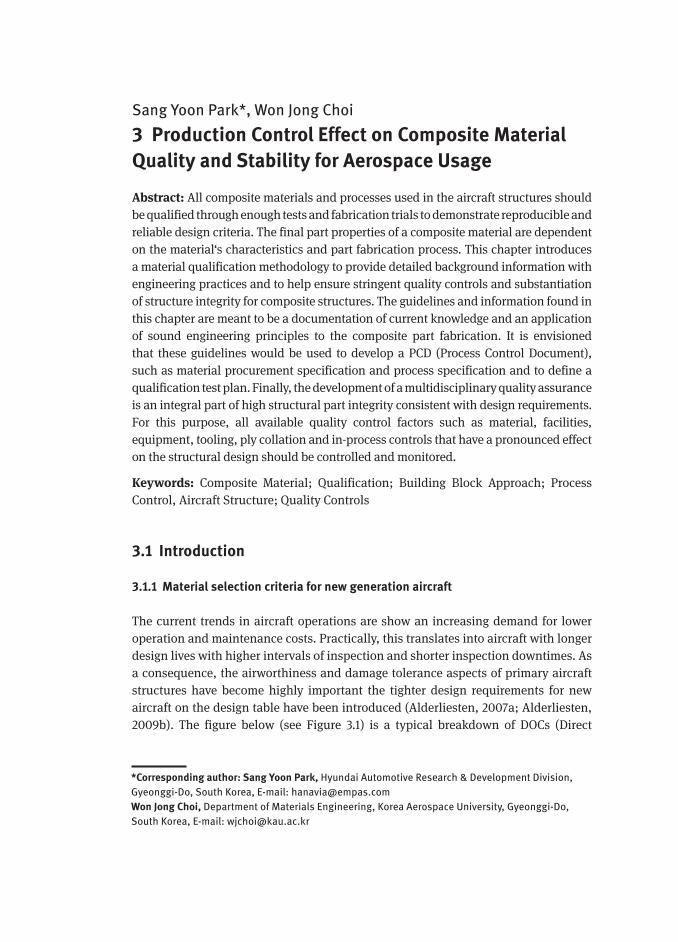
The current trends in aircraft operations are show an increasing demand for lower operation and maintenance costs. Practically, this translates into aircraft with longer design lives with higher intervals of inspection and shorter inspection downtimes. As a consequence, the airworthiness and damage tolerance aspects of primary aircraft structures have become highly important the tighter design requirements for new aircraft on the design table have been introduced (Alderliesten, 2007a; Alderliesten, 2009b). The figure below (see Figure 3.1) is a typical breakdown of DOCs (Direct
*Corresponding author: Sang Yoon Park, Hyundai Automotive Research & Development Division, Gyeonggi-Do, South Korea, E-mail: [email protected] Jong Choi, Department of Materials Engineering, Korea Aerospace University, Gyeonggi-Do, South Korea, E-mail: [email protected]
Introduction 113
Operating Costs) associated with the commercial aircraft (www.soton.ac.uk). The DOC used to compare aircraft in terms of economic performance can reflect a profit and loss approach, including non-cash items such as aircraft depreciation.
Figure 3.1: Commercial aircraft cost of ownership and breakdown of the DOCs for a typical commercial aircraft form (Muchiri, 2002).
Moreover, critical DOC terms such as training, financing and maintenance over the aircraft lifetime can be generally estimated based on an as-incurred basis (Gibson and Morrell, 2004). In particular, the high impact of the material selection on the DOC levels has been shown on: (1) materials (raw and/or semi-finished) and manufacturing costs, (2) fuel consumption (i.e. light-weight) and (3) maintenance costs (i.e. inspection, repair and replacement). Thus, the reduction in structural weight and simple maintenance procedures can reduce the DOC levels significantly. In parallel, manufacturing cost consideration, which involves reduced tool cost and shorter production times and reliable QC (Quality Control) methods, is also needed to provide better affordability and quality of the final parts.
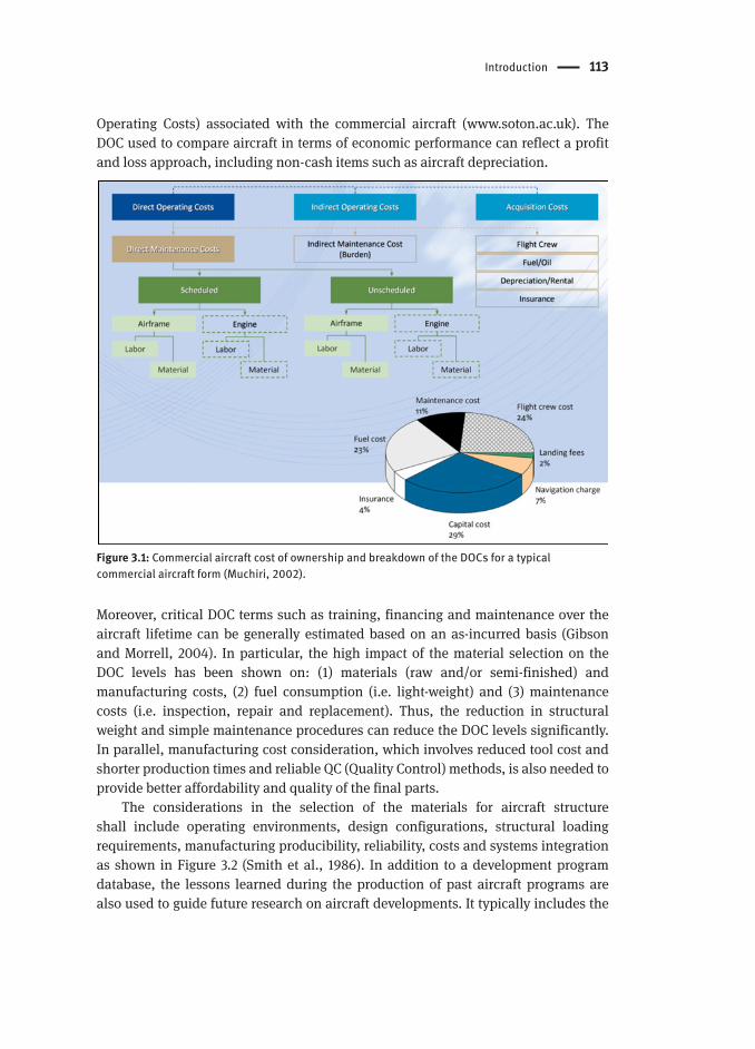
The considerations in the selection of the materials for aircraft structure shall include operating environments, design configurations, structural loading requirements, manufacturing producibility, reliability, costs and systems integration as shown in Figure 3.2 (Smith et al., 1986). In addition to a development program database, the lessons learned during the production of past aircraft programs are also used to guide future research on aircraft developments. It typically includes the
114 Production Control Effect on Composite Material Quality and Stability for Aerospace Usage
knowledge that was obtained during design, production and service. In addition, selection procedures and criteria used for secondary materials such as adhesives, honeycomb core, core splice materials, coatings and potting compounds are similar to those used for the primary structural materials (Smith et al., 1986; Niu, 1992).
Figure 3.2: Material selection criteria for airframe structures (Smith et al., 1986).
The introduction of advanced and new structural materials in aircraft structure took place in evolutionary steps which required an innovative design philosophy-which allowed for further optimization. Figure 3.3 shows the element of structural integrity management. Structural integrity is an essential element of airworthiness that can only be sustained by proactive management. This figure shows that most airframe structural development goes through the following phases: (1) design criteria, (2) specification of material and processing, (3) determination of allowable element strength and margins of safety and (4) experimental demonstration or a substantiation test program. It is the purpose of this chapter to discuss, in some detail, material selection and specification, process specification and quality control assurance methodology for part manufacture. This chapter also examines the current state and recent trends in process control for composite material quality and stability for aerospace usage.
Recently, the advances made in composite manufacture have allowed the aeronautical industry to significantly increase their use of composite material, particularly for carbon fiber reinforced plastics. For example, Boeing jumped from 12% on the 777 to 50% on the 787 while Airbus moved from 10% on the A340 to 25% on the A380 and finally to 53% on the A350XWB (Chady,2013; Marsh, 2008).Boeing became the first airliner to launch a full-size commercial aircraft with composite wings and fuselage in the 787 (Chady,2013; Rosa, 2007). The A350 XWB‘s wing is also made

Introduction 115
of lightweight carbon fiber composites. A comparison between the aircraft structural materials is summarized in Table 3.1 (Beumler, 2009).
Figure 3.3: Element of structural integrity planning.
Table 3.1: Aircraft design-material selection (Beumler, 2009).
Materials Strength Drawback
Metals (aluminum alloys) • Standardization and reparability
• Static behavior• Improvement potential
• High material density• Fatigue and corrosion - related problems• High costs of new alloys
Composites (CFRP) • Fatigue behavior• Low density and no corrosion• Best suited for light-weight
structures
Poor Impact behaviors• No plasticity• Reparability and recycling
It is well noted that the composite structures provide structural strength comparable to metallic alloys but at a lighter weight. This leads to improved fuel efficiency and performance from a commercial aircraft. It also offers real weight savings as a skin material, especially in the pressurized fuselage crown section, as shown in Figure 3.4(a) (www.airbus.com; Vogelesang & Vlot, 2000; Lin et al., 2005). The introduction of advanced composites has spurred innovations in manufacturing technologies. An estimated 40% of Airbus A380‘s structure and components are manufactured from the latest generation of carbon composites and advanced metallic materials (Jérôme,

116 Production Control Effect on Composite Material Quality and Stability for Aerospace Usage
2001). For this purpose, Airbus (Goranson, 1998) introduced the latest composite manufacturing technologies for A380 structures, including AFP (Automated Fiber Placement), ATL (Automated Tape Laying), RFI (Resin Film Infusion) and RTM (Resin Transfer Molding) and barrel-size autoclave cure techniques for curing fuselage crown section elements (Refer to Figure 3.4(b)).
This chapter addresses the structural integrity plan that takes place during the material selection, design and manufacturing technology development process of commercial aircraft. Subjects discussed include the role of material qualification methodology and criteria, stringent in-process quality controls and the substantiation of structure integrity used in the process of composite structure manufacture.
(a) Boeing 787
(b) Airbus A380
Figure 3.4: Application of composite structures on commercial aircraft structures (www.airbus.com; www.boeing.com).

Introduction 117
3.1.2 Structural Requirements for Certification
Carbon fiber reinforced laminate has received much attention as a candidate material for small aircraft (14 CFR Part 23) and civil aircraft (14 CFR Part 25) structures where the advantages of this material is its design tailorability, high specific strength/stiffness and fatigue resistance (Jedidi et al., 2006; Soutis, 2005; Wolfrum et al., 2009; Dexter et al., 1994). In particular, the next generation of civil aircraft from Airbus and Boeing both presents a multitude of firsts for the application of carbon fiber reinforced laminates in the primary structures, for example main wing and pressurized fuselage (Marsh, 2005; Reichl, 2007). In order for composite structure design to meet the FAR (Federal Aviation Regulation) certification requirements, it is required to demonstrate compliance with 14 CFR Part 25 Sec. 603 (Materials), Sec. 605 (Fabrication methods), Sec. 613 (Material strength properties and design values) and Sec. 609 (Protection of structure) as summarized in Table 3.2 (Code of Federal Regulations-Part 25).
Table 3.2: A summary of FAR Part 25 requirements for material specification, process specification and material allowables (Code of Federal Regulations-Part 25).
Amendment and title(Key requirements)
Summary
25.603Materials(Material Specification)
Suitability and durability established by experience or test Conform to specifications that assure strength Takes into account service environmental conditions
25.605Fabrication Methods(Process Specification)
Fabrication methods should produce consistently sound structure (repeatability)
If a fabrication process requires close control to reach this objective, the process must be performed under an approved process specification
New methods should be substantiated by test program.25.613Material Strength Properties and Design Values (Design Value)
Statistical based design value Design values must be chosen to minimize the probability
of structural failure: A-basis for single load path, B-basis for redundant structure.
1) Single load path structures must meet a 99% probability with 95% confidence statistics.
2) Redundant load path structures must meet a 90% probability with 95% confidence statistics.
Environmental effects
The specific program master plan shall cover the compliance to airworthiness standards, such as FAR, AC (Advisory Circular) and TSO (Technical Standard Order). In general, the certification of a composite structure follows the guidelines contained in the AC 20-107B (entitled in Composite Structures, in 2009). For damage tolerance, a composite structure is based on the substantiation rule for „No-Growth“ damage of sizes up to the allowable limit (Mohaghegh, 2005; U.S. Department of Transportation,

118 Production Control Effect on Composite Material Quality and Stability for Aerospace Usage
2009a). In addition, the environmental exposure which may result in material property degradation should be addressed in the static strength evaluation (Code of Federal Regulations-Part 25; Lee & Min, 2007; Code of Federal Regulations-Part 21). The following FAA ACs list the recommendations for showing compliance with FARs associated with composite material.
– AC 20-107B: Composite Structure – AC 21-26: Quality Control for the Manufacture of Composite Structures
According the FAA Part 21, the quality control system should include a detailed procedure that will ensure; (1) the quality of incoming materials, (2) The control of the in-process fabrication methods and (3) the evaluation of the final product for conformity to the design requirements (Code of Federal Regulations-Part 21).
Table 3.3: A summary of FAR Part 21 requirements for production inspection and quality control system (Code of Federal Regulations-Part 21).
Amendment and title Summary
21.123Production under a Type Certificate
Establish approved production inspection system
21.125Production Inspection System
Establish a production inspection system Specify materials used in the finished product in the type design data Process must be accomplished in accordance with industry or
United States specifications25.165Responsibility of Holder
Maintain the quality control system Maintain approved data and procedures: Engineering drawing
specify:1) Materials by the controlling Material Specification2) Processes by the controlling Process Specification3) Inspection and acceptance criteria
The quality control plan should be responsive to special engineering requirements that arise in individual parts or areas as a result of potential failure modes, damage tolerance and flaw growth requirements, loadings, inspectability and/or local sensitivities to manufacture and assembly. The further information of certificate management policies and guidance can be found in FAA Order, 8120.22 (FAA Order 8120.22, 2013) and 8120.23 (FAA Order 8120.23, 2013) and AC 21-43 (U.S. Department of Transportation, 2009b), respectively.
It is noted that general regulations/standards for composite structures are more stringent that what is normally done for metallic structure certification as tabulated in the metallic material properties development and standardization (Lee & Min, 2007; Seneviratne & Tomblin, 2012). One of the unique features of composite material is a degree of care needed in the material procurement specification and production process. Early experiences have shown that material qualification is the single most
Introduction 119
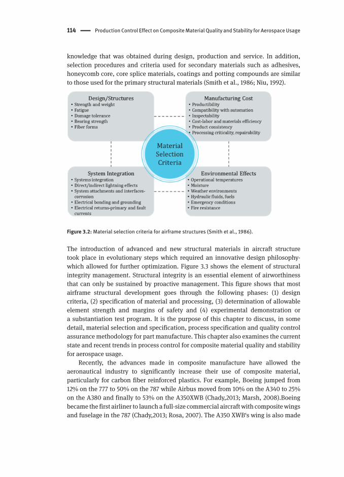
critical step, which cannot be disregarded, even for a tertiary-loaded structure, since it is fundamental to ensure the continued airworthiness of aircraft structure. Based on the above background, the CS&CI (Composite Safety and Certification Initiatives) program supported by FAA (Ilcewicz & Murphy, 2005; Ilcewicz, 2011) was created to address important technical issues for new material applications and composite structure certification approaches. This program has shown that the aircraft industry has been faced with a more complicated endeavor in achieving M&P (Material & Process) qualification and part QCs. Thus, both material procurement specifications and process documentation are needed to control composite part fabrication prior to either PPV (Pre-Production Verification), or FAQ (First Article Qualification) as summarized in Table 3.4 (Boeing Commercial Airplanes, 2010).
Table 3.4: PPV, FAQ and FAI (First Article Inspection).
PPV FAQ/FAI
Objective To demonstrate compliance with engineering requirement via drawing callout
To verify that everything has come together (specification, tool, KPPs and design details) to produce an acceptable part.
Description PPV is performed for cost and schedule risk mitigation.PPV verifies the readiness of a processor’s system to produce consistently acceptable structure.Allows for destructive evaluation of composite partsRequirement is levied on parts that meet one or more of the following:1) Complex design2) Complex tool3) New, unproven fabrication process4) New materials with little production historyPPV is one means of ensuring that the fabrication process is ready prior to FAQ.
Perform to verify form, fit and functionPerform for cost and schedule risk mitigationDemonstrates a processor’s ability to fabricate and inspect all parts in that family of partsFAQ is normally a requirement for all CFRP parts.Verifies that the processor can produce articles conforming to all drawing, specification, planning and all other documentation and contract requirements.
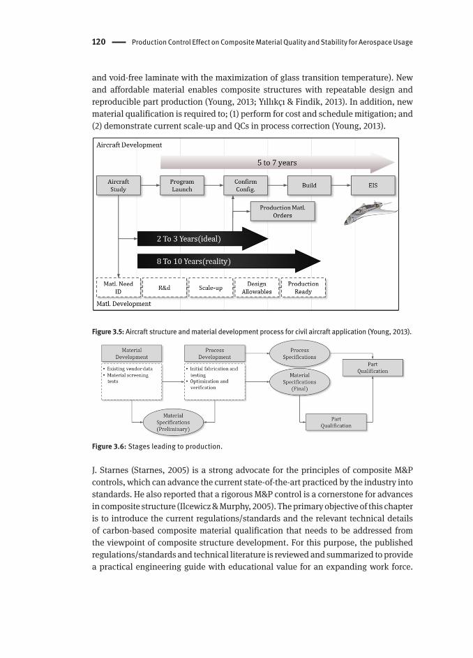
Since most properties of the composite structure in the final part are dependent on the constituent materials‘ characteristics (i.e. fiber/resin), the prepreg/lamina‘s properties and the part process robustness. These limitations are enough to yield a typical „over-load“ that is placed on the structure to account for these differences, based on the expected material variability factors. Figure 3.5 (Young, 2013) shows a new material development process in a timely fashion which is tied to a civil aircraft structure application. Most aircraft industries have been seeking and demanding new material systems and low-cost and optimum curing technique (higher fiber content
120 Production Control Effect on Composite Material Quality and Stability for Aerospace Usage
and void-free laminate with the maximization of glass transition temperature). New and affordable material enables composite structures with repeatable design and reproducible part production (Young, 2013; Yıllıkçı & Findik, 2013). In addition, new material qualification is required to; (1) perform for cost and schedule mitigation; and (2) demonstrate current scale-up and QCs in process correction (Young, 2013).
Figure 3.5: Aircraft structure and material development process for civil aircraft application (Young, 2013).
Figure 3.6: Stages leading to production.
J. Starnes (Starnes, 2005) is a strong advocate for the principles of composite M&P controls, which can advance the current state-of-the-art practiced by the industry into standards. He also reported that a rigorous M&P control is a cornerstone for advances in composite structure (Ilcewicz & Murphy, 2005). The primary objective of this chapter is to introduce the current regulations/standards and the relevant technical details of carbon-based composite material qualification that needs to be addressed from the viewpoint of composite structure development. For this purpose, the published regulations/standards and technical literature is reviewed and summarized to provide a practical engineering guide with educational value for an expanding work force.

Material Qualification Procedures 121
Finally, the experimental data is introduced for material acceptance and equivalency evaluations. Each of them is briefly addressed in the following discussion.
3.2 Material Qualification Procedures
3.2.1 BBA (Building Block Approach)
The objective of material qualification philosophy is to validate methods, processes and specifications to ensure that the engineering material requirements of the structural design are met with a high degree of confidence and reliability (U.S. Department of Transportation, 2002). It is noted that the design validation (to establish by proof) is accomplished through the verification (to prove by evidence) and the qualification (to define attributes or characteristics), combined with the M&P activities. A series of structural tests are generally conducted to provide a final validation of the success of these approaches and to fulfill a QA (Quality Assurance) that the structure will perform as intended in all respects: form, fit, function, reproducibility, durability and safety (Arthasartsri & Ren, 2009). The verification of a unique material‘s attributes and characteristics are typically determined based on a statistical approach through coupon level tests. Based on the above motivations, the composite material for aircraft usage places greater emphasis on; (1) material qualification; (2) PCDs (Process Control Documents) based on SPC (Statistical Process Control); and (3) QCs by M&P actions, respectively (Young, 2013).
In the aircraft development, a structural analysis alone is not considered adequate for the substantiation of a composite structure design. A BBA has been proposed in conjunction with structural analysis and M&P activities as shown in Figure 3.7. This is primarily achieved by establishing a sufficient process and QCs to manufacture parts and reliably substantiate the required strength by test and analysis at coupon, element, subcomponent and/or full-scale level structures (Mohaghegh, 2005; U.S. Department of Transportation, 2002).
Figure 3.7: Composite material and structure substantiation flow charts.
122 Production Control Effect on Composite Material Quality and Stability for Aerospace Usage
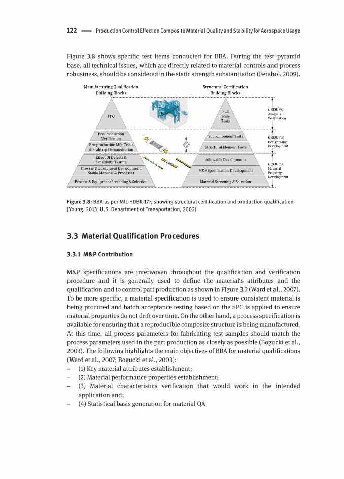
Figure 3.8 shows specific test items conducted for BBA. During the test pyramid base, all technical issues, which are directly related to material controls and process robustness, should be considered in the static strength substantiation (Ferabol, 2009).
Figure 3.8: BBA as per MIL-HDBK-17F, showing structural certification and production qualification (Young, 2013; U.S. Department of Transportation, 2002).
3.3 Material Qualification Procedures
3.3.1 M&P Contribution
M&P specifications are interwoven throughout the qualification and verification procedure and it is generally used to define the material‘s attributes and the qualification and to control part production as shown in Figure 3.2 (Ward et al., 2007). To be more specific, a material specification is used to ensure consistent material is being procured and batch acceptance testing based on the SPC is applied to ensure material properties do not drift over time. On the other hand, a process specification is available for ensuring that a reproducible composite structure is being manufactured. At this time, all process parameters for fabricating test samples should match the process parameters used in the part production as closely as possible (Bogucki et al., 2003). The following highlights the main objectives of BBA for material qualifications (Ward et al., 2007; Bogucki et al., 2003):
– (1) Key material attributes establishment; – (2) Material performance properties establishment; – (3) Material characteristics verification that would work in the intended
application and; – (4) Statistical basis generation for material QA

Material Property Development 123
The corporate strategy between material and process is illustrated in Figure 3.9. This figure shows that both material and process specifications are interwoven throughout the certification validation process.
Figure 3.9: Product design and corporate strategy: managing the connection for material and process.
3.4 Material Property Development
The objective of „Material Property Development“ is to come to an agreement on critical safety issues and airworthiness considerations combined with M&P qualifications as illustrated in Figure 3.10 (Young, 2013; U.S. Department of Transportation, 2002). In the GROUP A (refer to Figure 3.8), the material qualification tests are needed to verify the repeatability and reproducibility of the M&P specifications, which are directly related to the key properties that need to be addressed during material screening phase. This section is divided into three sub-sections, focusing on: (1) Material Screening and Selection, (2) Material and Process Specification Development and (3) Allowables Development. This section does not provide an overview of composite-related static strength requirements but rather, focus on two issues; (1) M&P qualifications and (2) material QCs.

124 Production Control Effect on Composite Material Quality and Stability for Aerospace Usage
Figure 3.10: GROUP A blocks in material property evaluation(Young, 2013; U.S. Department of Transportation, 2002).
3.4.1 Material Screening and Selection
„Material Screening and Selection“ is typically to gain data essential for specifying parameters and/or tolerance and to define a specific material procurement specification (including Grade, Type and Class) as well. The following issues should be considered in the material screening and selection phase:
– (1) ASE (Aircraft Service Exposure) - specify range of operating environments – (2) Glass transition temperature, Tg (hot/wet) consideration – (3) Selection tied to design/analysis requirements – (4) Compatibility with the production process (i.e. production feasibility
considerations)
3.4.2 Material and Process Specification Development
„Material and Process Specification Development“ is to validate the corresponding specifications and to capture the QC methods on a selected material system (U.S. Department of Transportation, 2002; Ferabol, 2009). In order to monitor KC (Key Characteristics) and KPP (Key Process Parameters), a subset of qualification testing is required for prepreg‘s physical, chemical and thermal tests and cured lamina physical tests as listed in Table 3.5 and Table 3.6, respectively (Tomblin et al., 2003). The properties as tabulated in these tables (based on a number of prepreg production batches) can be used to identify the fundamental characteristics of raw material and cure properties (U.S. Department of Transportation, 2002).

Material Property Development 125
Table 3.5: Physical/chemical property tests-prepreg (Tomblin et al., 2003).
Properties Methods No. of replicates per batch
Resin Content (wt.%) D 3529 3
Volatile Content (wt.%) D 3530 3
Gel Time (min.) D 3532 3
Resin Flow (%) D 3531 3
Fiber Areal Weight (g/m2) D 3531 3
FTIR A E 1252 3
HPLC B - 3
A FTIR (Fourier Transform Infrared)B HPLC (High Performance Liquid Chromatography)
Table 3.6: Cured-lamina physical property tests (Tomblin et al., 2003).
Properties Methods No. of replicates per batch
Fiber Volume (%) D 3171 A
Resin Volume (%) D 3171 A
Void Content (%) D 2734 A
Neat Resin Density (g/m3) D 792 B
Dry Tg (oC) C SRM 18R 3Wet Tg (oC) D SRM 18R 3A At least one test should be performed on each panel manufactured for qualification.B Data or neat resin sample should be provided by material supplier for each batch of material.C Tg (Glass Transition Temperature), dry samples are as-fabricated samples that have been maintai-ned at ambient conditions in an environmentally controlled laboratory.D Wet samples are humidity-aged until an equilibrium moisture weight gain is achieved.
3.4.3 Allowables Development
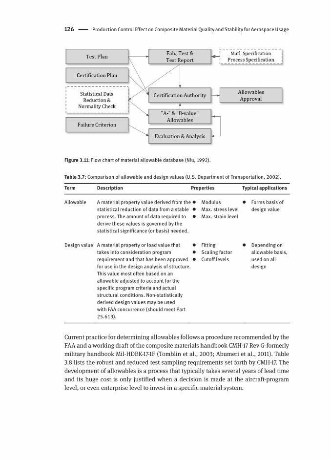
In „Allowable Development“, the material selected should be fully controlled by both material procurement- and process specifications as illustrated in Figure 3.11 (Niu, 1992). The objective is to establish a database based on a statistical approach. These allowables should reflect the material and process actually used in the part qualification and the scatter in the strength properties due to the variability in material and process should be characterized by proper allowables (U.S. Department of Transportation, 2009a; U.S. Department of Transportation, 2002). In common practice, the terms allowable and design value have been often misunderstood to be interchangeable. While both terms are related, they do not have the same meaning. The definitions of allowable and design values are given in Table 3.7.
126 Production Control Effect on Composite Material Quality and Stability for Aerospace Usage
Figure 3.11: Flow chart of material allowable database (Niu, 1992).
Table 3.7: Comparison of allowable and design values (U.S. Department of Transportation, 2002).
Term Description Properties Typical applications
Allowable A material property value derived from the statistical reduction of data from a stable process. The amount of data required to derive these values is governed by the statistical significance (or basis) needed.
Modulus Max. stress level Max. strain level
Forms basis of design value
Design value A material property or load value that takes into consideration program requirement and that has been approved for use in the design analysis of structure. This value most often based on an allowable adjusted to account for the specific program criteria and actual structural conditions. Non-statistically derived design values may be used with FAA concurrence (should meet Part 25.613).
Fitting Scaling factor Cutoff levels
Depending on allowable basis, used on all design
Current practice for determining allowables follows a procedure recommended by the FAA and a working draft of the composite materials handbook CMH-17 Rev G-formerly military handbook Mil-HDBK-17-1F (Tomblin et al., 2003; Abumeri et al., 2011). Table 3.8 lists the robust and reduced test sampling requirements set forth by CMH-17. The development of allowables is a process that typically takes several years of lead time and its huge cost is only justified when a decision is made at the aircraft-program level, or even enterprise level to invest in a specific material system.
Material Property Development 127
Table 3.8: FAA guidelines for robust and reduced sampling (Abumeri et al., 2011).
Category No. of batches No. of samples
A-Value Robust sampling 10 75Reduced sampling 5 55
B-Value Robust sampling 10 55Reduced sampling 3 18
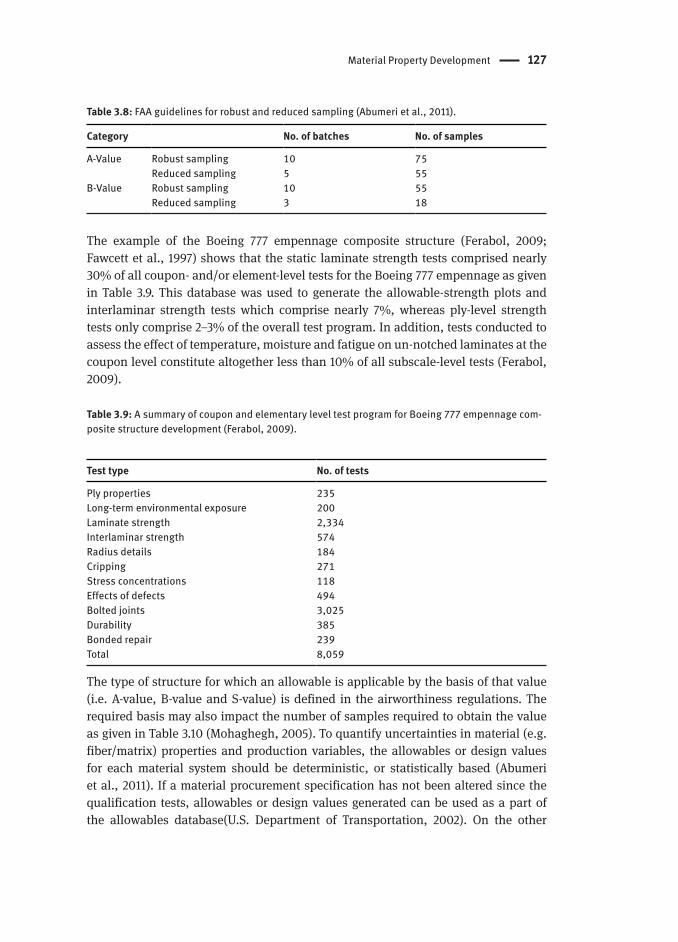
The example of the Boeing 777 empennage composite structure (Ferabol, 2009; Fawcett et al., 1997) shows that the static laminate strength tests comprised nearly 30% of all coupon- and/or element-level tests for the Boeing 777 empennage as given in Table 3.9. This database was used to generate the allowable-strength plots and interlaminar strength tests which comprise nearly 7%, whereas ply-level strength tests only comprise 2–3% of the overall test program. In addition, tests conducted to assess the effect of temperature, moisture and fatigue on un-notched laminates at the coupon level constitute altogether less than 10% of all subscale-level tests (Ferabol, 2009).
Table 3.9: A summary of coupon and elementary level test program for Boeing 777 empennage com-posite structure development (Ferabol, 2009).
Test type No. of tests
Ply properties 235Long-term environmental exposure 200Laminate strength 2,334Interlaminar strength 574Radius details 184Cripping 271Stress concentrations 118Effects of defects 494Bolted joints 3,025Durability 385Bonded repair 239Total 8,059
The type of structure for which an allowable is applicable by the basis of that value (i.e. A-value, B-value and S-value) is defined in the airworthiness regulations. The required basis may also impact the number of samples required to obtain the value as given in Table 3.10 (Mohaghegh, 2005). To quantify uncertainties in material (e.g. fiber/matrix) properties and production variables, the allowables or design values for each material system should be deterministic, or statistically based (Abumeri et al., 2011). If a material procurement specification has not been altered since the qualification tests, allowables or design values generated can be used as a part of the allowables database(U.S. Department of Transportation, 2002). On the other
128 Production Control Effect on Composite Material Quality and Stability for Aerospace Usage
hand, changes to the material and process specifications are often major changes in type design and should be addressed as such under 14 CFR part 21, subpart D (U.S. Department of Transportation, 2009a).
Table 3.10: Design allowable descriptions (Mohaghegh, 2005).
Basis Description No. of samples
A-Value 99% of population with a 95% confidence level. Single load-path structures
B-Value 90% of population with a 95% confidence level. Multiple load-path structures
S-Value A value associated with specification acceptance values (no statistical significance).
Initial designs, or part-by-part basis verification
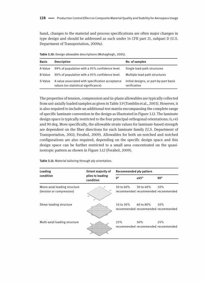
The properties of tension, compression and in-plane allowables are typically collected from uni-axially loaded samples as given in Table 3.9 (Tomblin et al., 2003). However, it is also required to include an additional test matrix encompassing the complete range of specific laminate convention in the design as illustrated in Figure 3.12. The laminate design space is typically restricted to the four principal orthogonal orientations; 0,±45 and 90 deg. More specifically, the allowable strain values for laminate-based strength are dependent on the fiber directions for each laminate family (U.S. Department of Transportation, 2002; Ferabol, 2009). Allowables for both un-notched and notched configurations are also required, depending on the specific design space and this design space can be further restricted to a small area concentrated on the quasi-isotropic pattern as shown in Figure 3.12 (Ferabol, 2009).
Table 3.11: Material tailoring through ply orientation.
Loadingcondition
Orient majority of plies to loading condition
Recommended ply pattern
0° ±45° 90°
Mono-axial loading structure (tension or compression)
50 to 60% recommended
30 to 40% recommended
10% recommended
Shear loading structure 10 to 30% recommended
60 to 80% recommended
10% recommended
Multi-axial loading structure 25% recommended
50% recommended
25% recommended

Material Property Development 129
Figure 3.12: Practical design space for orthogonal laminate families: laminate family convention = % of 0o / % of ±45o / % of 90o.
Table 3.12: Reduced sampling requirements for cured lamina main properties (Tomblin et al., 2003).
Properties Methods No. of replicates per batch
CTDA RTDB ETWC ETDD
0o (warp) tension modulus,strength & poisson‘s ratio
D 3039 3 6 3 6 3 6 3 6
90o (fill) tension modulus & strength D 3039 3 6 3 6 3 6 3 6
0o (warp) compression strength SRM 1R 3 6 3 6 3 6 3 6
0o (warp) compression modulus SRM 1R 3 6 3 6 3 6 3 6
90o (fill) compression strength SRM 1R 3 6 3 6 3 6 3 6
90o (fill) compression modulus SRM 1R 3 6 3 6 3 6 3 6
In-plane shear modulus & strength D 5379 3 6 3 6 3 6 3 6
Short beam shear D 2344 - 3 6 - -A CTD (Cold Temperature Dry): three batches of material required (test temperature=-65±5°F, moisture content = as-fabricated).B RTD (Room Temperature Dry): three batches of material required (test temperature=70±10°F, mois-ture content = as-fabricated).C ETW (Elevated Temperature Wet): Three batches of material required (test temperature=180±5°F, moisture content ).D ETD (Elevated Temperature Dry): Three batches of material required (test temperature=180±5°F, moisture content = as-fabricated).

130 Production Control Effect on Composite Material Quality and Stability for Aerospace Usage
3.5 Material and Process Control
A PCD controls a material system to offer consistent attributes and characteristics and it is required to cover all aspects of material control issues, such as raw material handling/shipment and KC and KPP controls based on SPC (John et al., 2008; Ng & Tomblin, 2008). Both KCs and KPPs are monitored for in-process QC and are available for review by end-users and certification agencies. All the KPPs‘ targets and tolerances are defined by engineering trials and re-evaluated on an ongoing basis. The effect of the representative prepreg characteristics on the performance of composite structures is shown in Figure 3.13 (John et al., 2008). Neat resin physical/chemical, fiber mechanics and un-cured prepreg properties play a major role in the load transfer mechanisms and the capabilities of a composite structure, particularly for OHT (Open Hole Tension), OHC (Open Hole Compression), bearing strength and so forth. Specific technical requirements of materials are also summarized in Table 3.13. The following key factors are required to document the material procurement specification (Davies, 2003):
– (1) Qualification data should be established based on a statistical approach for equivalency and/or QA acceptance requirements.
– (2) Documentation and database set for material characteristics shall exist for each unique material specification (including Grade, Type and Class).
– (3) Property drift (including upward shifts) in KC and KPP should be minimized by a specific SPC.
– (4) A process to evaluate different levels of change in the material production should be outlined.
Figure 3.13: Schematic view of the representative prepreg characteristics on the performance of composite structure (John et al., 2008).

Material and Process Control 131
Table 3.13: Technical requirement of prepreg for KC and KPP controls (McCarvill et al., 2003; Tomblin et al., 2001).
Definition Neat Resin Requirements Carbon Fiber/Fabric Requi-rements
Un-cured Prepreg Require-ments
Requirements Requirements of the chemical andphysical properties of the resin.
Requirements of the physical andmechanical properties of the fiber
Requirements for un-cured prepreg physical and chemical properties
Key Factors Resin components and their manufacturers should be specified in the PCD or specifications.
Recommended that the supplier develop a database of resin properties.
Although resin properties are not used in design, the database will enable processes to be developed with an fundamental knowledge and understanding of the resin composition and reactivity.
Resin requirements that measure key attributes of the final mix or premix(es) should be identified. In some cases this information may be considered proprietary and controlled in the PCD.
Fiber should be purchased to a specification tied to either the prepreg or fabric specification.
Fiber can meet the requirements of the prepreg specification when impregnated with the specified resin and processed per the specified cure procedure
Fiber specification should define the average values and ranges for all critical mechanical and physical properties
Fabric specification should establish the critical fiber properties, fabric areal weight and fabric style
Chemical properties such as HPLC, IR, chemical reactivity, flow and gel time should be determined
Fiber and resin content are important for part performance and volatile content is critical for part quality.
To capture down-the-length and across-the-width variability introduced in the filming and prepregging process steps, and test and evaluation should be conducted on the start and end of rolls and should also be conducted across the full width of the rolls
Test Items(ASTM Test Spec.)
Density (D792) Viscosity Gel time (D2471) IR (E1252) HPLC (ingredient ratios) Cure Kinetics (E2041) Rheology (E4473)
Form (E1309) Twist Size Count (D4018) Tension Modulus
(D4018) Tension Strength
(D4018) Density (D3800)
Fiber Content (D3529) Resin Content (D3529) Volatile Content (D3530) Flow (D3531) Gel Time (D3532) HPLC: Ingredient Ratios
(SRM 20R) IR: Ingredients Chemical
Signature (E1252) Chemical Reaction, DSC
(E1356, D3418) Tack/Drape

132 Production Control Effect on Composite Material Quality and Stability for Aerospace Usage
In addition, processor qualification is to establish a part control platform that must be approved by the certification agencies (i.e. MRA, Manufacturing Readiness Assessment). It is mandated to prove whether the QA system established is capable of maintaining a QC so that a part fulfills the criteria in type design. Any discrepancies permitted by the process specifications should also be substantiated through analysis supported by test evidence at the coupon, element, or subcomponent level (U.S. Department of Transportation, 2009a). The process specification in regard to the processor qualification should list the following items (Young, 2013):
– (1) Process documentation and personnel certification should be adequately detailed to ensure a repeatable fabrication method as a means of formal control.
– (2) QA monitoring production steps are needed for facility survey, review of equipment and material/part controls.
– (3) A process capability test-process demonstrates the ability to fabricate test panels and perform mechanical tests, by showing their process can meet the requirements.
– (4) SPC involves using control charts and capability index to monitor process stability and conformance.
– (5) Methods of inspection (including non-destructive inspection certification) should be consistent with those used for the parts production.
In addition, the QA system includes appropriate inspection documentation for incoming raw materials and parts. Further demands on part qualification are as follows (Code of Federal Regulations-14 CFR 21.125):
– (1) All raw materials, ancillary materials and parts should be properly identified if their physical, or chemical properties cannot be readily and accurately determined. Furthermore, both of them have to be inspected to demonstrate an acceptable quality level, the raw materials for composite structure are to be tested on receipt from the supplier(s) on a batch to batch basis.
– (2) Processes affecting the quality of the finished part should be accomplished in accordance with the acceptable industry standards or the relevant FARs.
– (3) All single parts, elements and/or components should be inspected for conformity with the type design data at points in production where accurate determinations can be made.
3.6 An Example Study: Material Acceptance and Equivalency
The following section will describe a proposed example of material acceptance and equivalency procedures for a carbon fiber composite material. This study is articulated in three sub-sections to briefly define; (1) Material Acceptance, (2) Material Equivalency and (3) Test Results and Analysis, respectively.

An Example Study: Material Acceptance and Equivalency 133
3.6.1 Material Acceptance
Material acceptance is known as material receiving inspection through a raw material QC testing in order to monitor property variations in the prepreg lot (Tomblin et al., 2003). It is a process of determining whether a specific material batch can meet the requirements of the applicable procurement specification. In general, a subset of the material acceptance tests is planned for key material characteristic evaluations, particularly for gel time, RC (Resin Content) and FAW (Fiber Areal Weight). The significant changes in the test result indicate a potential change in the material‘s properties. Most production practices emphasize statistical QC tools by using acceptance test data as well as process controls in order to monitor production trends and make real-time or near-real-time process corrections (McCarvill et al., 2003).
Supplier Testing: In the overall material qualifications, the material supplier is responsible for conducting material supplier testing (see Figure 3.7, prepreg material supplier spec.-physical/chemical property tests). At this time, the material procurement specification should be determined based on the number of rolls of each prepreg batch that is tested by the material supplier. Consequently, the supplier certification data should include: (1) applicable specifications, (2) physical/chemical properties, (3) specific test data and (4) locations of any defective areas in the materials, respectively.
Receiving Testing: The QA department of composite structure manufacture is responsible for performing the specified receiving tests as given in Table 3.14 on each prepreg batch. The aim of this testing is to verify the supplier test results and to ensure that the material has not changed or been changed during shipping. Table 3.14 provides an example of supplier certification and a purchaser‘s receiving test results for a 250°F-cured 3K plain weave carbon/epoxy prepreg. The procedures for receiving inspection do not allow for any changes in the material system. It should be performed for one roll from each separate material shipment. In addition, the QA department has a responsibility to generate the test results and allowing the prepreg to be released to the production site only upon satisfactory demonstration that the material meets the procurement specification‘s requirements.
Table 3.14: Example of aircraft manufacture acceptance test matrix and test results for 250°F-cured 3K plain weave carbon/epoxy prepreg.
Properties A Supplier Certification Receiving Inspection
Gel time (min.) B 10.0 ± 0.6 5.0 ± 0.0FAW (g/m2) C 191.0 ± 1.7 193.0 ± 0.0RC (wt.%) D 41.9 ± 0.9 42.1 ± 0.2A Above test results were based on the 3 replicatesB Material Specification‘s requirement = Avg. 3-13 min.C Material Specification‘s requirement = Ind. 193.0 ± 9.0 g/m2, Avg. 193.0 ± 8.0 g/m2
D Material Specification‘s requirement = Ind. 42.0 ± 3.0%, Avg. 42.0 ± 2.0%

134 Production Control Effect on Composite Material Quality and Stability for Aerospace Usage
3.6.2 Material Equivalency
This section briefly describes the requirements and procedures of material equivalency. The material equivalency program is specified to assure that a „follow-on“ material and/or „follow-on“ process will produce equivalent properties to those of the original qualification data (Tomblin et al., 2001). However, this methodology was only developed as a means to show compliance with 14 CFR Part 23 requirements (Tomblin et al., 2003). There are 5 levels of permissible changes for material equivalency as per DOT/FAA/AR-03/19 (Tomblin et al., 2003) and it is only applicable to the following specific types of changes (Tomblin et al., 2003; Zureick & Nettles, 2002):
– (1) Type-1: Identical material fabricated by the same airframe manufacturer using identical fabrication process at a different location,
– (2) Type-2: Identical material fabricated by a different airframe manufacturer using a follow-on process that is equivalent to the original process,
– (3) Type-3: Identical material fabricated by the same airframe manufacturer using a follow-on process that is slightly different from the original process,
– (4) Type-4: Minor changes in the prepreg constituent(s) and/or constituent production process, or
– (5) Type-5: Combinations of the above.
The material equivalency approach is limited to changes in the material‘s constituent(s), prepreg process and major part production changes. Major changes effect on the material allowables and/or the acceptance limits are given in the 14 CFR 21.93 - Classification of changes in type design (Code of Federal Regulations-14 CFR 21.93). Approval of minor and major changes are covered in the 14 CFR 21.95 - Approval of minor changes in type design (Code of Federal Regulations-14 CFR 21.95) and the 14 CFR 21.97 - Approval of major changes in type design(Code of Federal Regulations-14 CFR 21.97), respectively. A successful material equivalency demonstration does not imply that both follow-on material and/or the follow-on process will also yield equal properties at laminate, element, or subcomponent levels such that the production complexity of a particular application may result in different properties. To ascertain if there is any divergence of properties for more complex configurations, further tests, such as on elements and components, are needed to fulfill the part qualification requirements (Tomblin et al., 2001).
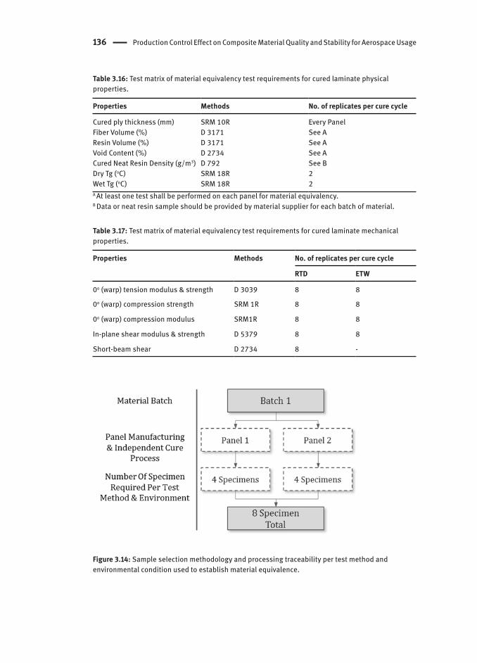
Test Matrix for Material Equivalency: Table 3.16 and Table 3.17 list the minimum requirements to substantiate a specific material equivalency at coupon level. Table 3.17 describes the minimum number of mechanical tests required for each environmental condition along with the relevant test standards to generate material equivalency data of B-value design allowable (Equal B). To incorporate the processing and/or the panel-to-panel variability, sampling selection was based on at least two independent cure cycles as shown in Figure 3.14 (Lee, 2006).

An Example Study: Material Acceptance and Equivalency 135
Table 3.15: Prepreg visual defects and their acceptable levels (Recommendations Only).
Levels/Definitions Examples
Level 0 Changes Change in typographical error corrections to the specification or PCD Change in the names of incoming materials due to company name
changes Change in storage facility locations
Level 1 Changes(Normal batch acceptance testing on the same or similar material)
Change in release (backing) paper or other process aid Alternate vendor for chemically and physically identical raw materials
(there should be compelling data verifying that the alternate material is identical to the original material)
Changes to packaging methods and materials Level 2 Changes(Approved with less than the full equivalency test plan required for a level 3 change)
Change in feedstock or precursor to resin ingredients Change in feedstock or precursor to fiber ingredients Second source of chemically and physically similar raw materials that
have not been shown to be chemical equivalents Changes to test methods that reduce variability Modifications to process equipment or processes that do not change KCs Addition of new similar equipment Expansion of existing facilities, including start-up of additional production
facility machinesLevel 3 Changes(Require full equivalency test program, such as defined in DOT/FAA/AR-03/19)
Change in fiber manufacturing process Change in fiber size type, size level, finish, or coupling agents Change in resin chemical characteristics (e.g. alternate resin ingredient) Change in viscosity of major resin components Change in manufacturing site for fiber, resin, or fabric Alternate weaver using same fiber and weave Change in resin mixing, filming and prepregging equipment, process and
KPPs that change KCs or KPPs Change in cure cycle (e.g. temperature, dwell time and pressure) Change in tack Change to/from autoclave from/to vacuum pressure cure Change in resin content (small, difference of less than 2% in resin content
by weight) Change in nominal number of fibers per tow
Level 4 Changes(Equivalency tests will not suffice for links to a previous material characterization. Changes require a new product identification (new specification designation) and a new qualification test program)
Change in resin composition Change in resin content (large, difference of 2% or more in resin content
by weight) Change in nominal number of fibers per tow (e.g. 3K fibers per tow to 6K) Change in fiber or fabric areal weight (e.g. 145 to 190 gm/m2) that
changes cured ply thickness Change in fiber type (e.g. T300 to AS4) Change in fiber manufacturer (e.g. Toray to Amoco) Change in type of fabric weave (e.g. plain weave to eight-harness satin) Addition of conductive fibers to the fabric (e.g. for lightning protection
purposes)
136 Production Control Effect on Composite Material Quality and Stability for Aerospace Usage
Table 3.16: Test matrix of material equivalency test requirements for cured laminate physical properties.
Properties Methods No. of replicates per cure cycle
Cured ply thickness (mm) SRM 10R Every PanelFiber Volume (%) D 3171 See AResin Volume (%) D 3171 See AVoid Content (%) D 2734 See ACured Neat Resin Density (g/m3) D 792 See BDry Tg (oC) SRM 18R 2Wet Tg (oC) SRM 18R 2A At least one test shall be performed on each panel for material equivalency.B Data or neat resin sample should be provided by material supplier for each batch of material.
Table 3.17: Test matrix of material equivalency test requirements for cured laminate mechanical properties.
Properties Methods No. of replicates per cure cycle
RTD ETW
0o (warp) tension modulus & strength D 3039 8 8
0o (warp) compression strength SRM 1R 8 8
0o (warp) compression modulus SRM1R 8 8
In-plane shear modulus & strength D 5379 8 8
Short-beam shear D 2734 8 -
Figure 3.14: Sample selection methodology and processing traceability per test method and environmental condition used to establish material equivalence.

An Example Study: Material Acceptance and Equivalency 137
3.6.3 Test Result and Analysis
Test Sample Fabrication: An equivalency testing program was performed to evaluate the situation of identical material with follow-on process by a different airframe manufacturer. The composite material selected in this study was a 250°F-cured 3K plain weave carbon/epoxy prepreg that is typically applied to the aircraft structure. For fabricating the testing samples, all laminated composite panels were fabricated by stacking multiple layers of prepregs in accordance with the process specification so that the test samples are representative of part production including defects consistent with the limits established by process acceptance criteria. The number of plies (with the stacking sequence) to meet the required panel thicknesses depended on the test standards adopted for each test. Each panel manufactured for use as test samples has a traceable reference edge (U.S. Department of Defense, 2002). A minimum eight samples was prepared as per test standard to facilitate statistically valid samplings (see Table 3.17). For each series of tests, the standard deviation V(x), coefficient of variation CV and B-value (B) can be defined as follows (U.S. Department of Defense, 2002):
(3.1)
where; xi is the measured property, n is the number of samples, E(x) is the sample mean and is the one-sided tolerance limit factor for the B-value.
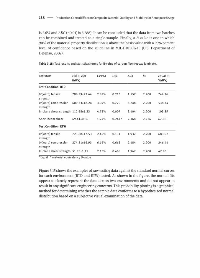
Test Results Evaluation for Material EquivalencyThe followings are experimental results and statistical analysis data from a 250°F-cured 3K plain weave carbon/epoxy tested at the RTD and 180°F wet (ETW) condition, respectively. Both experimental data and its statistical terms are summarized in Table 3.18, where average, CV, ADK (k-sample Anderson-Darling statistic), OSL (Observed Significance Level), and B-value are listed. In particular, the statistically based material properties with uncertainties were characterized as ADK, OSL and B-value, respectively. The term of OSL is the probability of observing an Anderson-Darling statistic at least as extreme as the value calculated if the data are from a normal distribution (Tomblin et al., 2003). If the OSL is ≤ 0.05, one may conclude (at a 5% risk of being in error) that the population is not normally distributed. All OSL values (except for RTD in-plane shear strength) as tabulated in Table 3.18 indicate that normal goodness-of-fit test yields an OSL value (0.131-0.720) greater than 0.05, there is sufficient evidence that the data are normally distributed. On the other hand, most ADK values are less than the critical value of ADK (ADC (=0.05) is 2.196, ADC (=0.0025)
138 Production Control Effect on Composite Material Quality and Stability for Aerospace Usage
is 2.657 and ADC (=0.01) is 3.288). It can be concluded that the data from two batches can be combined and treated as a single sample. Finally, a B-value is one in which 90% of the material property distribution is above the basis value with a 95% percent level of confidence based on the guideline in MIL-HDBK-17-1F (U.S. Department of Defense, 2002).
Table 3.18: Test results and statistical terms for B-value of carbon fiber/epoxy laminate.
Test item E(x) + V(x)(MPa)
CV (%) OSL ADK kB Equal B A(MPa)
Test Condition: RTD
0o(warp) tensile strength
788.79±22.64 2.87% 0.215 1.557 2.200 744.26
0o(warp) compression strength
600.33±18.24 3.04% 0.720 3.248 2.200 538.34
In-plane shear strength 112.68±5.33 4.73% 0.007 3.404 2.200 103.89
Short-beam shear 69.41±0.86 1.24% 0.2447 2.368 2.726 67.06
Test Condition: ETW
0o(warp) tensile strength
723.88±17.53 2.42% 0.131 1.932 2.200 683.02
0o(warp) compression strength
274.81±16.93 6.16% 0.663 2.484 2.200 246.44
In-plane shear strength 51.95±1.11 2.13% 0.468 1.967 2.200 47.90A Equal : B material equivalency B-value
Figure 3.15 shows the examples of raw testing data against the standard normal curves for each environment (RTD and ETW) tested. As shown in the figure, the normal fits appear to closely represent the data across two environments and do not appear to result in any significant engineering concerns. This probability plotting is a graphical method for determining whether the sample data conforms to a hypothesized normal distribution based on a subjective visual examination of the data.

An Example Study: Material Acceptance and Equivalency 139
(a) 0o (warp) tensile strength: RTD and ETW data
650 675 700 725 750 775 800 825 8500.0
0.1
0.2
0.3
0.4
0.5
0.6
0.7
0.8
0.9
1.0
Normal curve for ETW(OSL=0.131)
Normal curve for RTD(OSL=0.215)
RTD test data ETW test data
0o(warp) tensile strength
Prob
abilit
y of S
urviv
al
(b) 0o (warp) compression strength: RTD and ETW data
200 250 300 350 400 450 500 550 600 650 700 7500.0
0.1
0.2
0.3
0.4
0.5
0.6
0.7
0.8
0.9
1.0
Normal curve for ETW(OSL=0.663)
Normal curve for RTD(OSL=0.720)
RTD test data ETW test data
0o(warp) compression strength
Prob
abilit
y of S
urviv
al
Figure 3.15: Normal distribution of RTD and ETW strength values.
140 Production Control Effect on Composite Material Quality and Stability for Aerospace Usage
3.7 QCs for Composite Part Manufacturing
3.7.1 Manufacturing and QCs Procedure
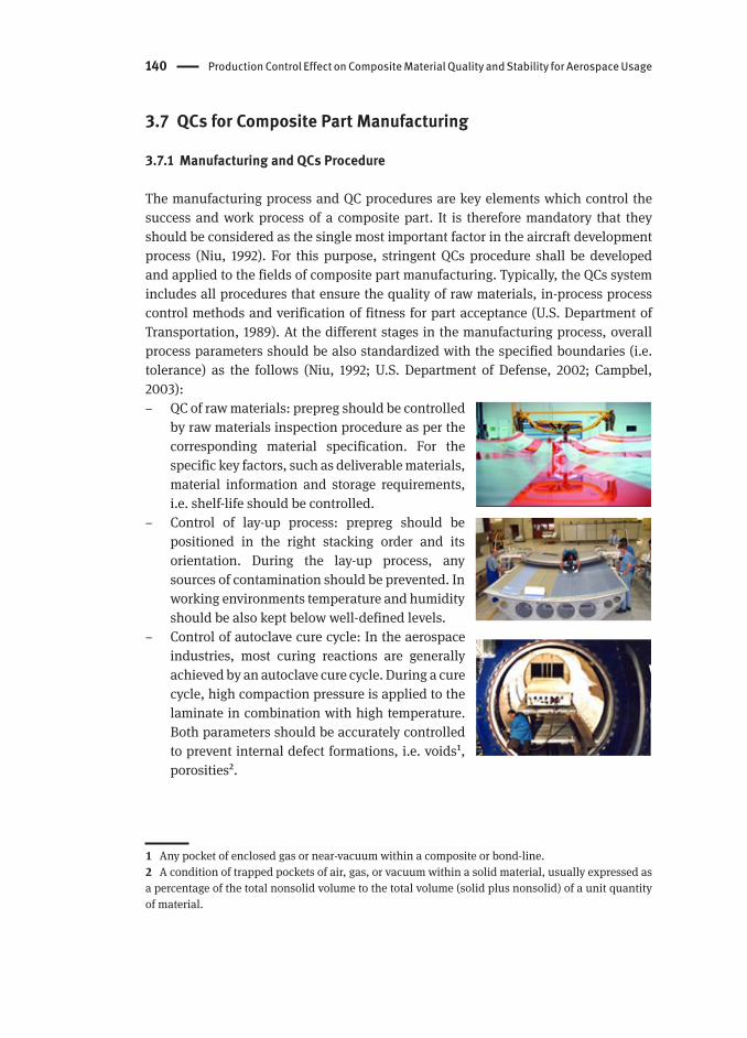
The manufacturing process and QC procedures are key elements which control the success and work process of a composite part. It is therefore mandatory that they should be considered as the single most important factor in the aircraft development process (Niu, 1992). For this purpose, stringent QCs procedure shall be developed and applied to the fields of composite part manufacturing. Typically, the QCs system includes all procedures that ensure the quality of raw materials, in-process process control methods and verification of fitness for part acceptance (U.S. Department of Transportation, 1989). At the different stages in the manufacturing process, overall process parameters should be also standardized with the specified boundaries (i.e. tolerance) as the follows (Niu, 1992; U.S. Department of Defense, 2002; Campbel, 2003):
– QC of raw materials: prepreg should be controlled by raw materials inspection procedure as per the corresponding material specification. For the specific key factors, such as deliverable materials, material information and storage requirements, i.e. shelf-life should be controlled.
– Control of lay-up process: prepreg should be positioned in the right stacking order and its orientation. During the lay-up process, any sources of contamination should be prevented. In working environments temperature and humidity should be also kept below well-defined levels.
– Control of autoclave cure cycle: In the aerospace industries, most curing reactions are generally achieved by an autoclave cure cycle. During a cure cycle, high compaction pressure is applied to the laminate in combination with high temperature. Both parameters should be accurately controlled to prevent internal defect formations, i.e. voids1, porosities2.
1 Any pocket of enclosed gas or near-vacuum within a composite or bond-line.2 A condition of trapped pockets of air, gas, or vacuum within a solid material, usually expressed as a percentage of the total nonsolid volume to the total volume (solid plus nonsolid) of a unit quantity of material.

QCs for Composite Part Manufacturing 141
– Post processing: The cured laminate generally requires some types of post-processing and/or assembly operations. However, the post-processing and assembly operations such as trimming, drilling and fastening require greater care because machining methods or incorrect process controls can results in heat damage or delamination in the cured laminate. During assembly, composite laminates will tend to delaminate if the excessive force is used to pull out gaps often encountered during assembly. In addition to the QC activities during the manufacturing process of the laminates, there is also a „final check“ prior to the part release. Non-destructive inspection, e.g. ultrasonic C-scanner and some mechanical tests are performed in the final step of QC.
3.7.2 In-process QCs
In-process QCs during composite part manufacturing are essential if the fits, forms, functions and requirements designed into a part are to be consistently achieved. It is reported that the QC systems used in the manufacturing of composite parts have been typically based on the government standards, company‘s own specifications, part requirements and engineering drawings. For this purpose, all available QC factors such as prescribed contractual requirements, available equipment, level of personnel training and documentation systems should be considered. The cause and effect diagram for exploring possible causes of defect build-up is represented in Figure 3.16. This figure shows that most promising factors for defect build-up are material, design, tooling, lay-up, labor (workmanship) and environment (facility controls).
Figure 3.16: In-process defect build-ups and management system (Grover, 2001).
142 Production Control Effect on Composite Material Quality and Stability for Aerospace Usage
The range of values that need to be evaluated for critical variables to establish tolerance limits should be stated in the applicable process specifications (Grover, 2001). At this time, the use of statistical design of experiments can minimize the unnecessary test items and cut the testing budget. Typical composite laminate lay-up process would include review and confirmation of the following items:
– (1) Incoming raw material(s) conformity, including material supplier, DOM (Date Of Manufacturer), batch number, roll number and total accumulated hours of working life
– (2) Released engineering requirements (includes process specifications and engineering drawing)
– (3) Verification that the release agent has been applied and cured on a clean tool surface
– (4) Approved planning documents, including part and serial number – (5) Inspection of prepreg lay-ups to assure engineering drawing requirements for
number of plies and orientation are met. – (6) In-process controls of critical processes and parameters, such as material out
time and autoclave pressure, autoclave load number – (7) SPC data collection of key process variables to ensure process capability and
performance – (8) Verification of dimensional and configuration conformity
Depending on the requirements of the development program, design verification is an essential step in the development of any composite structure. Also referred to as qualification procedures, design verification ensures that the part as designed is the same as the part as intended. For this purpose, quality control planning shall be utilized to the extent necessary to assure all process characteristics and features conform in all respects to the relevant requirements.
As mentioned in the above section, all in coming materials to be used in part manufacturing shall conform to their relevant material specifications. In addition, all processing aids used in the manufacturing shop should comply with the accepted specifications. Ply collation (i.e. ply lay-up) should be controlled to ensure the consistent dimensional accuracy of a cured part. The facility environment (i.e. tool preparation and lay-up area) should conform to requirements such as temperature, humidity and cleanliness. Finally, all equipment should be qualified within the specified calibration limits. To meet the requirements as above mentioned, the part manufacturer should prepare a set of quality management planning that controls facilities and equipment operation, procedures and training program for the sequence of tasks associated with the lay-up process as shown in Figure 3.17.
As mentioned in the above section, the properties of a composite material have been found to be strongly dependent on fabrication methods, whenever the same material is applied. Therefore, it is essential that each KPP and its monitoring method is recorded. A better understanding of the KPPs and their potential effect on material

Part Manufacturer Qualification 143
properties may allow a composites part manufacturer to minimize material variability. The following chapters consider those quality control principles which are applied, from raw materials inspection to verification of fitness for use of the final component, with reference to the production experience of some airframe manufacturers. The guidelines described in this section should not be viewed as policy or as the single acceptable method for composite part fabrication. It is meant to be a documentation of current knowledge and the application of sound engineering principles to composite part fabrication.
Figure 3.17: Typical sequence of lay-up process.
3.8 Part Manufacturer Qualification
The part manufacturer needs to be qualified in order to demonstrate compliance with the requirements of the relevant process specification(s) invoked by the applicable engineering drawing(s) or requirements. The ultimate aim of part manufacturer qualification is to validate that the process used by a different part manufacturers should produce properties that are equivalent to the original, i.e. with the initial qualification and allowable data (U.S. Department of Defense, 2002). Part manufacturer qualification is generally carried out as a part of the certification process. The following survey and certification shall be done in accordance with the standard, specification and requirements:
– (1) Facility survey: Review of equipment, QA system, materials/parts control and inspection capabilities to ensure that the facility can produce acceptable parts
– (2) Process capability tests: Part manufacturer demonstrates ability to build panels and perform mechanical tests, showing their process can meet the requirements
– (3) SPC3 involves using control charts and capability indices to monitor process stability and conformance
3 SPC is a systematic method for measuring, graphing, tracking and managing variations. SPC charts in themselves do not control processes. They provide only information so part manufactures can make process improvements.

144 Production Control Effect on Composite Material Quality and Stability for Aerospace Usage
– (4) Personnel certification: A means of formal control for designated operations or activities
In general, the part manufacturer qualification consists of three elements: (1) property equivalency verification, (2) manufacturing level inspection and (3) engineering compliance. Each of these elements is discussed below.
3.8.1 Property Equivalency Verification
The property equivalency shall be addressed by using process control specimens in order to verify the compliance with the process specification requirements as part of the part manufacturer qualification process. The aim of this is to validate that their processes yield properties, which are from the same statistical population as the qualification and allowables data. The process control specimen is shall be processed concurrently and identically to the process specification. In general, critical or safety-of-flight parts may require complete physical and mechanical property equivalency verification (Bogucki et al., 2003). A series of physical and mechanical properties shall meet the test values require by material specification. During early composite material production, most part manufacture required tests for 0° flexure strength and modulus and short beam shear strength. However, in recent years, these tests have been changed to require glass transition temperature, per ply thickness, fiber volume, void content and ply count on samples taken from designated areas on the part. Table 3.19 shows an example of process control property tests.
Table 3.19: Process control property tests (Tomblin et al., 2003).
Properties Methods No. of replicates per batch
Cured laminate density (g/m3) D 792 3Fiber Volume (%) D 3171 3Resin Volume (%) D 3171 3Average Cured Ply Thickness (mm) SACMA SRM 10 10 locationsTg (oC) R 18 3
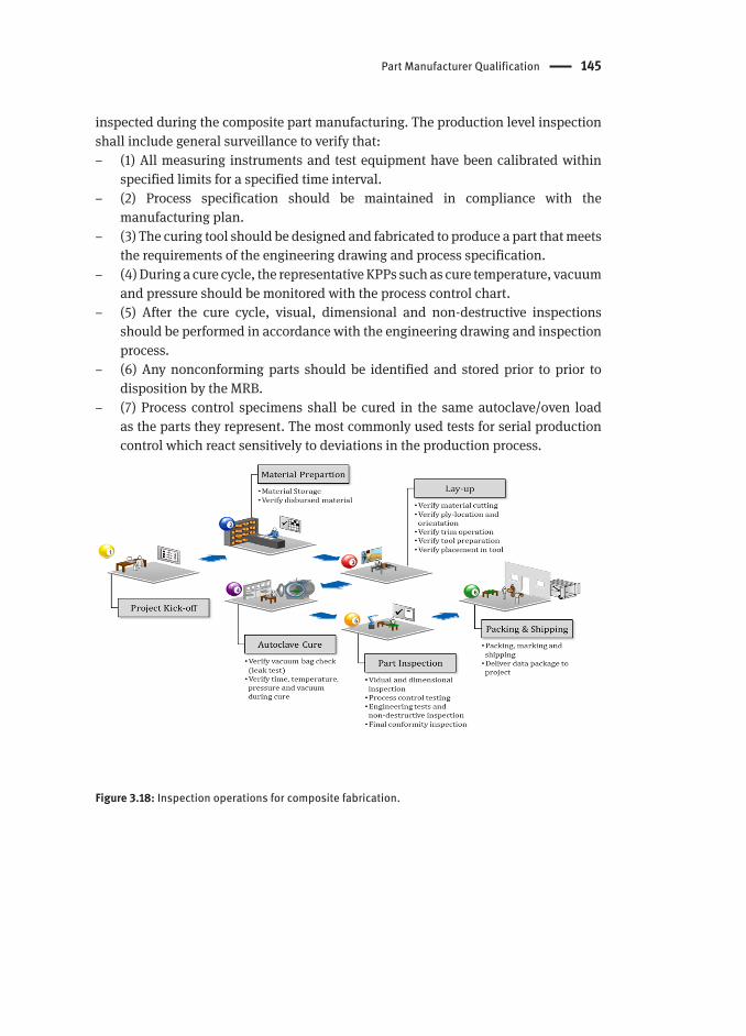
3.8.2 Production Level Inspection
Production level inspection is generally supplemented by a production control system which is driven by process data. The following diagram shown in Figure 3.18 gives the interaction of manufacturing level inspections to be performed. This figure demonstrates that critical steps and operations (including material preparation, ply collation, autoclave cure and part inspection) should be closely controlled and
Part Manufacturer Qualification 145
inspected during the composite part manufacturing. The production level inspection shall include general surveillance to verify that:
– (1) All measuring instruments and test equipment have been calibrated within specified limits for a specified time interval.
– (2) Process specification should be maintained in compliance with the manufacturing plan.
– (3) The curing tool should be designed and fabricated to produce a part that meets the requirements of the engineering drawing and process specification.
– (4) During a cure cycle, the representative KPPs such as cure temperature, vacuum and pressure should be monitored with the process control chart.
– (5) After the cure cycle, visual, dimensional and non-destructive inspections should be performed in accordance with the engineering drawing and inspection process.
– (6) Any nonconforming parts should be identified and stored prior to prior to disposition by the MRB.
– (7) Process control specimens shall be cured in the same autoclave/oven load as the parts they represent. The most commonly used tests for serial production control which react sensitively to deviations in the production process.
Figure 3.18: Inspection operations for composite fabrication.
146 Production Control Effect on Composite Material Quality and Stability for Aerospace Usage
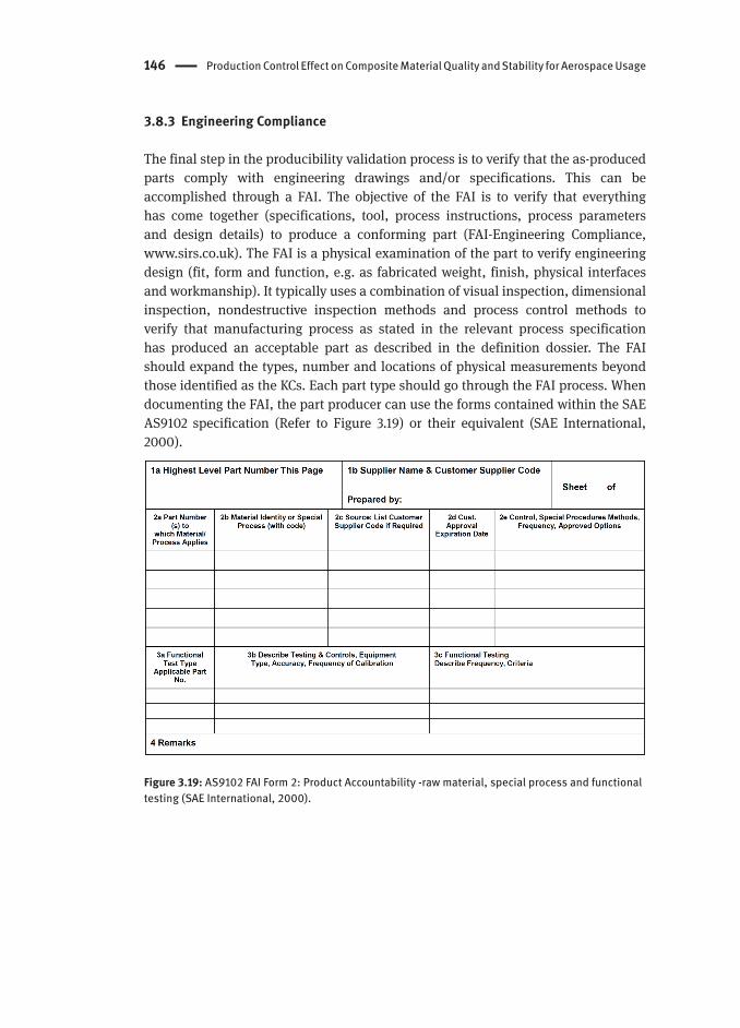
3.8.3 Engineering Compliance
The final step in the producibility validation process is to verify that the as-produced parts comply with engineering drawings and/or specifications. This can be accomplished through a FAI. The objective of the FAI is to verify that everything has come together (specifications, tool, process instructions, process parameters and design details) to produce a conforming part (FAI-Engineering Compliance, www.sirs.co.uk). The FAI is a physical examination of the part to verify engineering design (fit, form and function, e.g. as fabricated weight, finish, physical interfaces and workmanship). It typically uses a combination of visual inspection, dimensional inspection, nondestructive inspection methods and process control methods to verify that manufacturing process as stated in the relevant process specification has produced an acceptable part as described in the definition dossier. The FAI should expand the types, number and locations of physical measurements beyond those identified as the KCs. Each part type should go through the FAI process. When documenting the FAI, the part producer can use the forms contained within the SAE AS9102 specification (Refer to Figure 3.19) or their equivalent (SAE International, 2000).
Figure 3.19: AS9102 FAI Form 2: Product Accountability -raw material, special process and functional testing (SAE International, 2000).

Process Specification Guidelines 147
3.9 Process Specification Guidelines
The ultimate aim of process specifications is to establish the pertinent process parameters used for the conversion of materials into structural components and control material variability. Since the ultimate properties and qualities of composite laminates are significantly dependent on the KPPs. For this purpose, the pertinent process parameters and material effects should always be documented to aid in process control and solve troubleshooting. The process specification shall be detailed since most composite materials are sensitive to the process variations and the end-item requirements require stringent quality control. As described in Figure 3.9, both material and process specifications are inter-woven throughout the certification validation process in the BBA. The example specification is based on the format defined in MIL-STD-961 (U.S. Department of Transportation, 2008) as given in Table 3.20.
Table 3.20: Summary of process specification.
Chapter Title A General Description
I Scope Defines the purpose or application of the specification.II Applicable Documents List all the supporting documents, reports, specifications,
or standards referenced within the process specification.III Requirements Define the required process procedures and end item
requirements.3.1 Personnel3.2 Required materials3.3 Required equipment3.4 Facilities3.5 Tooling3.6 Required procedures-cure cycles
IV QA Define all the examinations, inspections and tests to be performed in order to verify that the processes, as well as the equipment, specified in the requirements section are followed.
V Notes Contain definitions and relevant information.A This format is only provided as an example format and requirements and limits for these critical items should be stated in the user process specifications.
3.9.1 Work instructions
Work instructions (also referred to as work orders) contain the procedures to be used in the fabrication process (Bogucki et al., 2003). Process specifications define the engineering requirements of a manufacturing process while the work instruction describes and defines the parameters of a manufacturing process on step-by-step

148 Production Control Effect on Composite Material Quality and Stability for Aerospace Usage
work level as shown in Figure 3.20. Past experiences demonstrated that detailed step-by-step process instructions in conjunction with process specifications have been found to be a successful approach for the fabrication of repeatable quality laminates. All steps from receiving of materials to forming of preforms to demolding should be inspected, or verified to process instructions. In addition QA shall establish appropriate procedures to identify any deviations of process parameters from the requirements stated in the process instructions. The following information is typically required to review each process control record.1. Prepreg manufacturer, lot number, material specification number, DOM and DOE2. Lay-up time, date and operator3. Cure date, cycle number and identification4. Autoclave pressure, temperature and time5. Process control panel test values6. P/N (Part Number) and S/N (Serial Number)
Figure 3.20: Manufacturing process in accordance with FAR Part 25.605: requirement and implementation.
3.9.2 Material Requirements
For consistency and standardization purposes, a general format for composite prepreg material specifications should be followed. The following is a recommended format that follows the standard format of MIL-STD-961 (U.S. Department of Transportation, 2008) and SAE AMS specifications. Other formats with the same content are also acceptable to the FAA. A general description of material specification is given in Table 3.21.

Process Specification Guidelines 149
Table 3.21: Summary of material specification.
Chapter Title A General Description
I Scope Defines the purpose or application of the specification
II Applicable Documents
List all the supporting documents, reports, specifications, or standards referenced within the process specification
III Requirements Define the required process procedures and end item requirements3.1 Definitions (Type, Class and Grade)3.2 Material requirements (resin, fiber, roll requirements, defects and storage, handling and out-time)3.3 Uncured prepreg requirements 3.4 Cured prepreg requirements (physical and mechanical properties)3.5 Material characterizations
IV Qualification Define all the examinations, inspections and tests to be performed in order to verify that the material4.1 Changes to qualified materials 4.2 Supplier site qualification4.3 Statistical process control 4.4 Product certification 4.5 Test methods 4.6 Test panel fabrication
V Preparation Delivery Marking, packing and shipping requirements
VI Notes Contain definitions and relevant information
A This format is only provided as an example format.
Primary structural materials (e.g. prepreg, film adhesive, honeycomb core) which are directly applied to the composite structures shall be qualified to their own material specification. In addition, all materials (and their sources) required for part manufacturing and requirements relevant to the materials should be listed within the process specifications. However, consumable materials which are mentioned in a process specification may not be part of completed structure (e.g. vacuum bagging materials) but still have great potential for affecting the quality of the structure. For this purpose, the consumable materials shall primary be controlled by the supplier‘s COC (Certificate Of Compliance) with minimal testing. Table 3.22 summarizes the consumable processing aid materials used in the composite part fabrication and they are typically separated into two categories based on allowed usage as follows:1. Contact-use materials: approved for use in direct contact with the part lay-up
(deliverable materials) inside the trim line prior to completion of cure.2. Noncontact-use materials: approved for use as aids to processing but shall not
contact the deliverable materials inside the trim line prior to cure.

150 Production Control Effect on Composite Material Quality and Stability for Aerospace Usage
Table 3.22: Processing aid materials for prepreg lay-up.
Contact-use materials Noncontact-use materials
Products Materials Products Materials
Parting film Fluorinated ethylene propylene (FEP), Polytetrafluoroethylene (PTFE),Tetrafluoroethylene (TFE), Ethylene tetrafluoroethylene (ETFE)
Vacuum bag Nylon film and cured silicone rubber
Polyvinylacetate, polyvinylchloride, polyethylene and nylon films for room temperature vacuum bags
Protective gloves
Rubber Latex, Polyethylene and Nylon
Breather/Bleeder
Fiberglass tape and polyester mat
Dry peel ply Nylon and polyester fabric Surface breather
Fiberglass tape and polyester paper
Rigid sweeps Polyethylene, Polyacetal, Polyurethane and Nylon
Solvents Acetone, ASTM D 329 Methyl ethyl ketone (MEK), ASTM D 740, Type I Butyl alcohol, ASTM D 1007 Methyl isobutyl Ketone
(MIBK),ASTM D 1153
Protective clothing
Protective clothing, (such as caps, coats, pants, sleeves, shoe covers) shall provide sufficient coverage to protect the part from contact with clothing or shoes
Protective clothing shall not release lint or other substances which would be detrimental to part fabrication
Prepreg material freezer storage conditions (temperature) and storage life or shelf life limits should be defined in the material specification. The storage life is the allowable time that the prepreg remains useful under its controlled storage condition (in typical from 6 to 12 months at -18°C or lower temperature) and continues to meet the specifications of its intended use. Out-time is the period of time that the prepreg remains useful outside of its recommended storage environment. The definitions of storage, handling life and out-time are shown in Figure 3.21.
In general, out-time can be classified into two categories. The first refers to the work life and it begins when the prepreg is removed from freezer storage and ends with the placement of the prepreg onto the tool. The second is mechanical or tool life. Mechanical life begins at placement of the ply on the tool and ends when the cure cycle is completed. In accordance with FAA regulations, it is also recommended that the tracking of material shall be carried by the material supplier to document out-time from DOM to the arrival to the end-user (Mohammad, 2013). Once a prepreg roll is removed from the refrigerator for use, total cumulative out-time of the material should be recorded and maintained for each prepreg roll including pre-kit for material traceability.

Process Specification Guidelines 151
Figure 3.21: Recommended definitions of storage, handling life and out-time.
3.9.3 Facility Requirements
The prepreg lay-up is generally undertaken in a CCA (Controlled Contamination Area) with free of contaminates. A CCA is an environmentally controlled area with a low level of environmental pollutants such as dust, airborne, aerosol particles and chemical vapors (refer to Figure 3.22). More accurately, a CCA has a controlled level of contamination that is specified by the number of particles per cubic meter at a specified particle size. The control of airborne particles is essential to maintaining a clean environment for the fabrication of composite laminates. ISO 14644-1 Class 9 is recommended as the minimum level of filtration for a CCA (ISO, 1999a). The airborne cleanliness classification standard (particle/m) according to ISO classification is shown in Table 3.23. To give some perspective, the ambient air outside in a typical urban environment contains 35,200,000 particles per cubic meter in the size range 0.5 μm and larger in diameter, corresponding to an ISO 14644-1 Class 9 CCA.
Table 3.23: Classification table proposed in ISO 14644-1 Class 9 (ISO, 1999a).
ISO ClassificationNumber
Maximum concentration limits (particles/m)
0.1 0.2 0.3 0.5 1.0 5.0
ISO Class 1 10ISO Class 2 100 24 10ISO Class 3 1,000 237 102 35ISO Class 4 10,000 2,370 1,020 352 83ISO Class 5 100,000 23,700 10,200 3,520 832ISO Class 6 1,000,000 237,000 102,000 35,200 8,320 298ISO Class 7 352,000 83,200 2,930ISO Class 8 3,520,000 832,000 29,300ISO Class 9 35,200,000 8,320,000 293,000
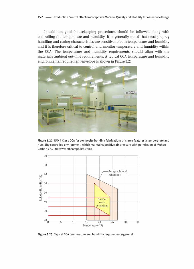
152 Production Control Effect on Composite Material Quality and Stability for Aerospace Usage
In addition good housekeeping procedures should be followed along with controlling the temperature and humidity. It is generally noted that most prepreg handling and curing characteristics are sensitive to both temperature and humidity and it is therefore critical to control and monitor temperature and humidity within the CCA. The temperature and humidity requirements should align with the material‘s ambient out-time requirements. A typical CCA temperature and humidity environmental requirement envelope is shown in Figure 3.23.
Figure 3.22: ISO 9 Class CCA for composite bonding fabrication: this area features a temperature and humidity controlled environment, which maintains positive air pressure with permission of Muhan Carbon Co., Ltd (www.mhcomposite.com).
Figure 3.23: Typical CCA temperature and humidity requirements-general.

Process Specification Guidelines 153
The following actions also help to minimize the generation of airborne particles. For composite processing, the documented procedure (i.e. QMS, Quality Management System), as described in Table 3.24 shall be in compliance with customer requirements or in the AC7118 audit process (SAE International, 2004).1. Tool release agent shall be fully cured prior to moving the tool into the CCA.2. Do not allow sanding, machining, or any other operation that generates dirt,
dust, or other debris in the CCA.3. Do not allow an air tool to be used without special precautions against
contaminating parts with the oil suspended in most shop air.4. The inclusion of a positive-pressure ventilation system in the CCA is an effective
method of preventing the introduction of airborne particles from other parts of the facility, such as machine shops.
Table 3.24: CCA and EMA controlled processes NADCAP (SAE International, 2004).
Process CCA EMA
Core cutting, slicing, sanding and machining Not allowed AllowedCore potting (fastener locations) and core splicing Allowed AllowedOther core fabrication using uncured prepreg, film adhesive or foaming adhesive
Allowed Not allowed
Core stabilization with thermoset resin Allowed A AllowedCore trimming Allowed AllowedCore forming Allowed B Allowed B
Localized core forming with a heat gun Allowed AllowedMinor sanding Allowed A AllowedCutting / kitting of prepreg or adhesive Allowed Allowed C
Cutting / kitting of dry fabric Allowed A Allowed A
Lay-up of prepreg or adhesive on exposed tool Allowed Not allowedLay-up of materials on hydraulic press and/or using electric matched metal press
Not allowed Allowed
Lay-up of preforms and braids Allowed AllowedWet lay-up (secondary bonding) Allowed A AllowedTackifying preforms or braids Allowed Not allowedFilament winding Allowed AllowedAerosol tackifying Allowed A AllowedAdhesive reticulation Allowed AllowedMixing of resin Allowed A AllowedLiquid resin infusion Allowed A AllowedCompression molding including cutting and kitting, lay-up and formingAllowed AllowedMiscellaneous bonding such as potting inserts, abradable application Allowed A AllowedStorage of unprotected core details, surface treated metallic details, pre-cured not metallic pats
Allowed Allowed B
A require segregation: B unless a documented degreasing procedure for subsequent cleaning exists: and C require double side carrier
154 Production Control Effect on Composite Material Quality and Stability for Aerospace Usage
3.9.4 Curing tools
The tool to be used for lay-up is subject to tool proofing/qualification procedures. This demonstrates that the tool is capable of producing parts that conform to drawing and specification requirements, when used with the specified materials, lay-up and bagging methods and cure profile (Niu, 1992; U.S. Department of Defense, 2002). Generally, having a composite structure within narrow tolerances is one of the most important challenges for part manufacturers in the aerospace industry. Being able to consider the process-induced deformations within the tool design stage will, on the one hand, directly lead to reduced assembly costs due to less shimming efforts and, on the other hand, less time consuming and costly tool rework and redesign, respectively. The potential requirements for curing tool are as follows:1. Identified and traceable to the corresponding engineering P/N2. Stable at use temperature (in typical 177°C)3. Smooth finish in cure part area4. Locate and support all bagging assembly and require vacuum integrity5. Uniform heat-up rate and lightweight6. Compatible to shop equipment7. Capable of manufacturing part in accordance with process specification and
engineered drawing requirements
For a part with concave corners, it is important that the prepreg plies fit down into the radius and do not bridge. If they bridge during lay-up, it will usually result in resin rich corners that contain porosity and/or voids after curing. The effect of tool selection (male versus female tool) on the dimensional tolerance is summarized in Table 3.25.
The thermo-mechanical properties of tooling materials have evolved to be such that they more closely match those of the production part to be fabricated. Typically, tools for composite manufacturing have generally been made of isotropic materials including steel and alloys such as Invar and their CTE (Coefficients of Thermal Expansion) values range from 0.8 (Invar 36) to 6.7×10⁻⁶/°F (Steel).For anisotropic material such as carbon fiber/epoxy and carbon fiber/bismaleimide (BMI) composites, the CTE value depends on fiber orientation; composite has less thermal strain in the fiber direction than in the transverse direction. The comparison of tool material is given in Table 3.26.
Table 3.27 gives thermal mass, thermal conductivity coefficient and CTE for the most commonly used tool material. High quality steel tool are common choices since they are less expensive and usually involves shorter lead times. However, the weight of the tools makes it difficult to handle and the CTE mismatch between the steel tool materials and the composite often is too extreme for use with close-tolerance composite parts (Lee, 2006).

Process Specification Guidelines 155
Table 3.25: Effect of tool selection on dimensional tolerance.
Tool types General characteristics Key Issues
(a) Male tool Preferred over outer surface tool, lower layup costRadius smaller than above will fracture fiber filament and cause radius thinningLargest allowable radius should be used to reduce rejections.
Straight edge: Plies will conform to radiusComplex contour: Resin rich, wrinkles develop on bag sideFiber form into wrinkles: bag sideAllow for sanding to meet contour requirements.Smaller than above radius will fracture fiber filament and cause radius thinning
(b) Female tool Fabrication on outer surface tool should be specified only when inner surface tool cannot produce satisfactory partLayup can produce resin rich area or fiber bridging or high porosity in corner, if the radius is smaller than aboveLargest allowable radius should be used to reduce rejections
If radii < 50 mm1) Greater effort required to form fabric into contour2) High potential for rejection and rework3) Surface resin starvation because of ply bridging and resin rich corner
Table 3.26: Comparison of tool materials.
Materials Advantages Disadvantages
Carbon fiber epoxy Excellent dimensional stability
Good heat-up rate Low cost Complex shape Low weight
Limited temperature Limited durability Plaster model required
(see Figure 3.24)
Steel Compatible CTE Long tool life
Machining is slow High tool weight Slow heat-up weight
ElectroformedNickel
Compatible CTE Long tool LIFE Good heat-up rate
Size limitation Cost Model required
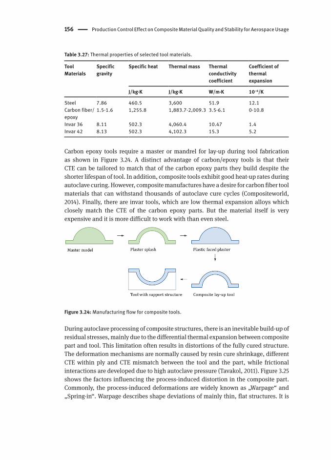
156 Production Control Effect on Composite Material Quality and Stability for Aerospace Usage
Table 3.27: Thermal properties of selected tool materials.
ToolMaterials
Specificgravity
Specific heat Thermal mass Thermalconductivitycoefficient
Coefficient ofthermalexpansion
J/kg·K J/kg·K W/m·K 10–6/K
Steel 7.86 460.5 3,600 51.9 12.1Carbon fiber/epoxy
1.5-1.6 1,255.8 1,883.7-2,009.3 3.5-6.1 0-10.8
Invar 36 8.11 502.3 4,060.4 10.47 1.4Invar 42 8.13 502.3 4,102.3 15.3 5.2
Carbon epoxy tools require a master or mandrel for lay-up during tool fabrication as shown in Figure 3.24. A distinct advantage of carbon/epoxy tools is that their CTE can be tailored to match that of the carbon epoxy parts they build despite the shorter lifespan of tool. In addition, composite tools exhibit good heat-up rates during autoclave curing. However, composite manufactures have a desire for carbon fiber tool materials that can withstand thousands of autoclave cure cycles (Compositeworld, 2014). Finally, there are invar tools, which are low thermal expansion alloys which closely match the CTE of the carbon epoxy parts. But the material itself is very expensive and it is more difficult to work with than even steel.
Figure 3.24: Manufacturing flow for composite tools.
During autoclave processing of composite structures, there is an inevitable build-up of residual stresses, mainly due to the differential thermal expansion between composite part and tool. This limitation often results in distortions of the fully cured structure. The deformation mechanisms are normally caused by resin cure shrinkage, different CTE within ply and CTE mismatch between the tool and the part, while frictional interactions are developed due to high autoclave pressure (Tavakol, 2011). Figure 3.25 shows the factors influencing the process-induced distortion in the composite part. Commonly, the process-induced deformations are widely known as „Warpage“ and „Spring-in“. Warpage describes shape deviations of mainly thin, flat structures. It is
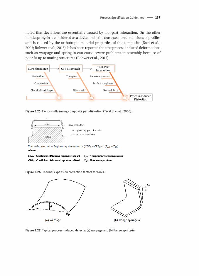
Process Specification Guidelines 157
noted that deviations are essentially caused by tool-part interaction. On the other hand, spring-in is considered as a deviation in the cross-section dimensions of profiles and is caused by the orthotropic material properties of the composite (Nuri et al., 2005; Rohwer et al., 2013). It has been reported that the process-induced deformations such as warpage and spring-in can cause severe problems in assembly because of poor fit-up to mating structures (Rohwer et al., 2013).
Figure 3.25: Factors influencing composite part distortion (Tavakol et al., 2003).
Figure 3.26: Thermal expansion correction factors for tools.
Figure 3.27: Typical process-induced defects: (a) warpage and (b) flange spring-in.
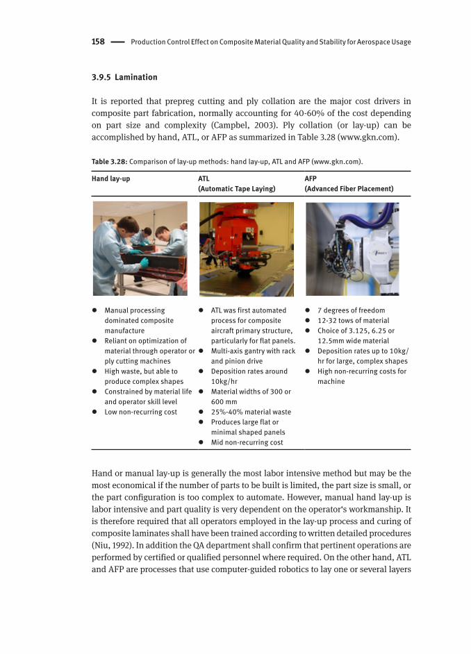
158 Production Control Effect on Composite Material Quality and Stability for Aerospace Usage
3.9.5 Lamination
It is reported that prepreg cutting and ply collation are the major cost drivers in composite part fabrication, normally accounting for 40-60% of the cost depending on part size and complexity (Campbel, 2003). Ply collation (or lay-up) can be accomplished by hand, ATL, or AFP as summarized in Table 3.28 (www.gkn.com).
Table 3.28: Comparison of lay-up methods: hand lay-up, ATL and AFP (www.gkn.com).
Hand lay-up ATL (Automatic Tape Laying)
AFP (Advanced Fiber Placement)
Manual processing dominated composite manufacture
Reliant on optimization of material through operator or ply cutting machines
High waste, but able to produce complex shapes
Constrained by material life and operator skill level
Low non-recurring cost
ATL was first automated process for composite aircraft primary structure, particularly for flat panels.
Multi-axis gantry with rack and pinion drive
Deposition rates around 10kg/hr
Material widths of 300 or 600 mm
25%-40% material waste Produces large flat or
minimal shaped panels Mid non-recurring cost
7 degrees of freedom 12-32 tows of material Choice of 3.125, 6.25 or
12.5mm wide material Deposition rates up to 10kg/
hr for large, complex shapes High non-recurring costs for
machine
Hand or manual lay-up is generally the most labor intensive method but may be the most economical if the number of parts to be built is limited, the part size is small, or the part configuration is too complex to automate. However, manual hand lay-up is labor intensive and part quality is very dependent on the operator‘s workmanship. It is therefore required that all operators employed in the lay-up process and curing of composite laminates shall have been trained according to written detailed procedures (Niu, 1992). In addition the QA department shall confirm that pertinent operations are performed by certified or qualified personnel where required. On the other hand, ATL and AFP are processes that use computer-guided robotics to lay one or several layers

Process Specification Guidelines 159
of prepreg tape or tows onto a mold to create a part or structure (Compositesworld, 2014b; Ginger, 2011). In general ATL is advantageous for flat or mildly contoured skins, such as large thick wing skins (Campbel, 2003). AFP machine is generally used for the manufacture of large-scale, complex-shaped structures composed of composites (Blom, 2010). Most commercially available AFP machines have seven axes of motion and are computer controlled. The axes of motion, i.e. three position axes, three rotation axes and an axis to rotate the work mandrel, provide the AFP machine with flexibility to position the fiber placement head onto the part surface, eventually enabling the production of complicated composite parts (Blom, 2010).
Most prepregs consist of fiber reinforcement pre-impregnated with B-stage thermoset resin in controlled quantities. They have a limited shelf-life and should be kept in a freezer in specified storage conditions and these shelf-life materials should be either scrapped or retested for acceptance after their expiration date. Frozen prepreg in the sealed moisture proof bag or container should be warmed such that no condensation forms on the moisture proof bag or container when wiped dry. If there is moisture dissolved in resin, it will directly affect the quality of the composite part and performance. The length of time required to warm the prepreg to ambient temperature is dependent on the prepreg roll size. For example, small rolls (5 to 10 pounds) can reach room temperature in 2 to 3 hours, while 30- to 50-pound rolls can take over 6 hours (Bogucki, 2003). After completion of warming, the prepreg can be opened in the CCA with protective gloves.
The prepreg shall be cut over a clean, non-contaminated surface with clean, sharp knives or cutting machine to minimize distortion and splitting and the pre-cut materials (i.e. kit) should be stored in flat or stress-free condition to prevent folding or further damage. Unless otherwise specified by the engineering drawing (e.g. net trim laminates), detail ply patterns should have a suitable trim at required locations to keep irregular edges out of the final trimmed part. All individual plies should be identified and traceable to meet the corresponding requirements on the engineering drawing. All cut prepregs should be sequentially prepared and collated on the tool in the location and orientation as defined by the engineering drawing or shop process instruction. The back film (i.e. separator film) of each ply should not be removed until a ply placement onto the lay-up. Prior to ply collation, the quality of all prepreg plies has to be judged directly by visual inspection. Typical prepreg defects are summarized in Figure 3.28. The prepreg fabric shall be clean and free from creases, cuts, tears, adjacent warp or fill yarns. Typical weaving anomalies are fuzz ball, crease or wrinkle, waviness, missing pick baggy cloth, broken warp (or fill), pulled-in filling and weave separation. All nonconforming areas shall not be used for production.

160 Production Control Effect on Composite Material Quality and Stability for Aerospace Usage
Figure 3.28: The representative defect in a woven fabric: the detail defect type is available in DOT/FAA/AR-06/10 (Ward et al., 2007).
Ply location accuracy requirements are normally specified on the engineering drawing or applicable process specification. For manual hand lay-up, a computer controlled laser projection system with low-intensity laser beams may be utilized for precision control of ply location, especially on tapered or contoured parts. The most commercially available laser projection system is a three-dimensional laser template-system that eliminates the need for physical templates by precisely projecting a laser template onto the curing tool to guide operators through the complex ply lay-up process. The position accuracy is generally ranges from ±0.34 mm at a distance of 4.5 m to ±0.8 mm at 9.1 m distance, respectively. Tolerance of ply lay-up orientation, location and splice is dependent on the specific engineering drawing requirements or process specification. Typical tolerance values of ply orientation, location and splice are given in Table 3.29.
Table 3.29: Typical ply tolerance according to reinforcement type: fabric and unidirectional tape.
Parameters Tolerance
Ply orientation tolerance
Fabric ±5°
Tape ±3°
Ply location tolerance Full plies Oversize
Partial plies and doubler ±0.25 mm
Ply splicing tolerance Fabric For butt splice, no overlap, to 2.5 mm gap
For overlap splice,13-25 mm
Tape(no cut fibers)
For butt splice, no overlap, to 2.5 mm gap
For overlap splice,not available

Process Specification Guidelines 161
Prepreg splice requirements according to structural type (solid laminate and sandwich panel) and ply orientation are summarized in Table 3.30. All splice joints should be offset from any other splice joint among any fifth (or sixth) consecutive plies through the thickness of the lay-up. For unidirectional tape, there should be no overlaps in areas that would become faying surfaces as shown in Figure 3.29.
Figure 3.29: Prepreg Splice Requirements: butt splice unidirectional tape.
Table 3.30: Prepreg splice requirements according to structure type and ply orientation.
Type A Prepreg Orientation Overlap Butt splice Overlap min. length require-ment B
Solidlaminate
Tape 0° direction See C Splice gap 1.5mm (no overlap)
25 mm
90° direction See C Not allowed 25 mmFabric 0°/90° direction 13 to 25 mm No gap allowed 25 mm
Sandwich panel D
Tape 0° direction Max. 5 mm No gap allowed C 25 mm90° direction See C Not allowed 25 mm
Fabric 0°/90° direction 13 to 25 mm Not allowed 25 mmSandwich panel with filler and doubler ply D
Tape 0° direction See C Splice gap 1.5mm(no overlap)
25 mm
90° direction See C Not allowed 25 mmFabric 0°/90° direction See C Splice gap 1.5mm
(no overlap)25 mm
A Splices may cross within a lay-up.B Stagger butt and overlap splices 25 mm, minimum. Stagger pattern may be repeated every fifth ply as shown in Figure 3.30.C Only applicable when required by engineering drawingD Transition overlap splices into butt splices near the faying region in accordance with Figure 3.31.
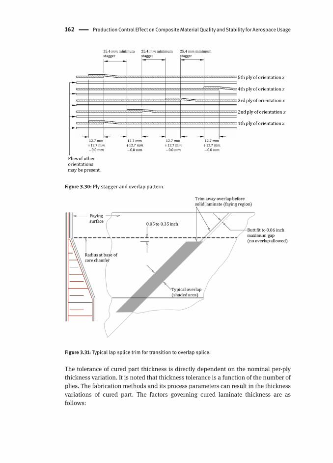
162 Production Control Effect on Composite Material Quality and Stability for Aerospace Usage
Figure 3.30: Ply stagger and overlap pattern.
Figure 3.31: Typical lap splice trim for transition to overlap splice.
The tolerance of cured part thickness is directly dependent on the nominal per-ply thickness variation. It is noted that thickness tolerance is a function of the number of plies. The fabrication methods and its process parameters can result in the thickness variations of cured part. The factors governing cured laminate thickness are as follows:

Process Specification Guidelines 163
1. Amount of bleed-out during a cure cycle: the correct amount of bleed out of the laminate is critical to processing a laminate with the correct fiber volume fraction. In typical, resin bleed-out is affected by vacuum pressure, initial resin content, resin flow (i.e. viscosity) and consumable process materials such as release film (if use perforated film) and bleeder materials (Ashraf, 2006). It is noted that the changes in bag bleed results in fiber volume variation, combined with the laminate qualities.
2. Cure pressure (i.e. autoclave cure pressure): the cure pressure has the greatest influence upon final laminate average thickness. It also has the greatest influence upon final laminate void content (Matthew et al., 1997).
3. First dwell-temperature: The low temperature ramp-and-hold step is generally called „dwell-stage (also refer to the B-stage)“. This stage allows the viscosity to remain at a lower value for a long period, assuring a greater resin flow and a more uniform compaction (Hou &Jensen, 2008). The resultant residual volatile content and residual fluidity of the epoxy resin remaining inside the composite are determined by the B-stage. It is reported that significant prepreg layup thickness reductions occur during the first temperature hold, the second temperature ramp and the second temperature hold at 177°C. This reduction does not occur during a single autoclave curing phase.
Extra filler plies may be used in areas of complex contours to prevent voids. Filler plies shall be the same material as used in the part and may be either unidirectional tape or fabric. Filler plies may be butted to or ramped up chamfered core edge as follows (refer to Figure 3.32):1. Butted plies are used to provide a smooth transition from edge band onto the
core chamfer. Plies at the core edge shall either touch or extend onto the core chamfer to accommodate core edge waviness. 1.5 mm maximum gap is allowed as given in Table 3.30.
2. Staggered plies are used to prevent filler plies from moving away from the core edge, thus causing a depression or void. A ramping of at least two filler plies onto the core chamfer is recommended. Extend the longest filler ply approximately 13 mm up the core chamfer. Stagger the remaining filler plies on the core chamfer at equal spacing to produce a smooth transition. The longest filler ply may be the first or last ply ramped up the core.

164 Production Control Effect on Composite Material Quality and Stability for Aerospace Usage
Figure 3.32: Filler ply lay-up.
Most composite parts are flat since the thickness of each ply is uniform throughout. In practice, however, tapering of laminates is necessary in many structural components. This tapering (known as ply drop-off) can be introduced by terminating plies at different locations. Figure 3.33 shows the laminate tapers from a thick section to a thin section as a result of the ply drop-off. However, ply drop-off results in a discontinuity area within the laminate and therefore, it introduces structural difficulties, for example stress concentration at the drop station. This limitation leads to failure of the components through delamination and/or failure of thermoset resin. The formation of interlaminar stresses at the drop-off may initiate failure long before the ultimate load carrying capacity of the laminate is reached. In most cases, the recommended ply drop-off lay-up pattern is as follows (Niu,1992):1. Ply drop-off should be as symmetrical and balanced as possible.2. Distance between ply drop-off steps should be at least, in typical 3.8 to 6.35 mm
as shown in Figure 3.33 with a large tolerance if possible.3. Ply drop-off should always be tapered and the slope angle should not exceed 10
degree as shown in Figure 3.33.4. Ply drop-off should not involve over 6 to 8 plies based on the nominal one ply
thickness of 0.13 mm or over 2 to 3 plies for thicker ply thicknesses.5. Ply drop-off should not occur on outer surface plies to avoid peeling.6. Cover all ply steps with at least on continuous outer ply to aid in load redistribution
and prevent edge delamination.

Process Specification Guidelines 165
Figure 3.33: Ply drop-off plies.
After the lay-up process, a sealed bag technique is mandatory for the autoclave curing of the prepreg. The definition of consumable material for vacuum bag assembly is summarized in Table 3.31. It is generally carried out by placing the lay-up under a vacuum bag and pulling a minimum of 980 mbar for up to 30 minutes (Cytec Industrial Materials,2013). Recommended bagging procedures for solid laminate and honeycomb core sandwich panel are shown in Figure 3.34. Once a full vacuum is attained, the vacuum source is then isolated for several minutes (in typical 5 minutes) and a static gauge is used to determine if the bag contains any leaks. If the required vacuum cannot be maintained, the vacuum bag assembly should be inspected and repaired to provide a leak-proof bag. Once the vacuum bag has been successfully leak checked and the thermocouples applied, it is ready for loading into the autoclave cure. If the lay-up structure contains a honeycomb core, the maximum vacuum that should be applied during leak checking or cure is 270 to 340 mbar since higher vacuums have been known to cause core migration and even crushing due to the differential pressure that can develop in the core cells.
Finally, vacuum bagging quality control is one of process parameters because improper bagging can result in part defect. The representative defect types that result from improper bagging are (Vijaya et al., 2013): fiber wrinkle, bridging, over-bleed or under-bleed, high porosity, out-of-tolerance and so forth. It is typically observed that the improper bagging during a cure cycle is due to (1) improper vacuum leak test, (2) improper placement of vacuum valves during bagging, (3) leakage in vacuum hoses and valves, (4) resin block in tool vacuum lines and (5) malfunctioning of vacuum controllers and solenoid valves.

166 Production Control Effect on Composite Material Quality and Stability for Aerospace Usage
Table 3.31: Typical consumable materials for vacuum bag assembly (Cytec Industrial Materials, 2013; Gurit AG., 2013; Hexcel Corporation., 2013).
Discrepancy Acceptable limits Contact or non-contact with prepreg
Bag Film Vacuum bagging film is an expendable polyamide film or reusable elastomer. This film is sealed on all sides of the stacked prepreg using sealant tape. A vacuum is then applied to apply atmospheric pressure to the cured part.
Noncontact-use
Breather The function of the breather fabric is to create even pressure around the part and at the same time allow entrapped air and volatiles to escape during a cure cycle. The breather should connect directly to the vacuum ports, where two or three additional layers of breather should be applied locally.
Noncontact-use
Flash Tape Flash tapes are typically used within a vacuum stack to locate and secure vacuum consumable materials as the component is being „bagged“ and throughout the component‘s cure cycle. This is particularly important on components being built with vertical, inclined or even overhanging surfaces.
Noncontact-use
Peel Ply A peel ply can be used if required. In general peel ply is recommended when a bonding surface is required. It is a woven fabric that is generally applied as the last material in the laminate sequence. As mentioned above this surface is then ideally prepared for secondary bonding, filling or painting and does not usually require any further mechanical abrasion
Contact-use
Release Film Release film is used to separate and release the laminate from the vacuum stack. It is supplied both as perforated and non-perforated. In particular the perforated film (with pin pricks) is designed to allow the passage of only air and volatiles into the breather layer above.
Contact-use
Sealant Sealant tape is used to provide an integral seal between tool and vacuum bag. Most sealant tapes are manufactured from a blend of synthetic rubbers combined with inert fillers, plasticizers and tackifiers. These provide the optimum combination of properties required for sealing against a variety of tool surfaces, such as composite and metal and for the subsequent curing of the composite.
Noncontact-use
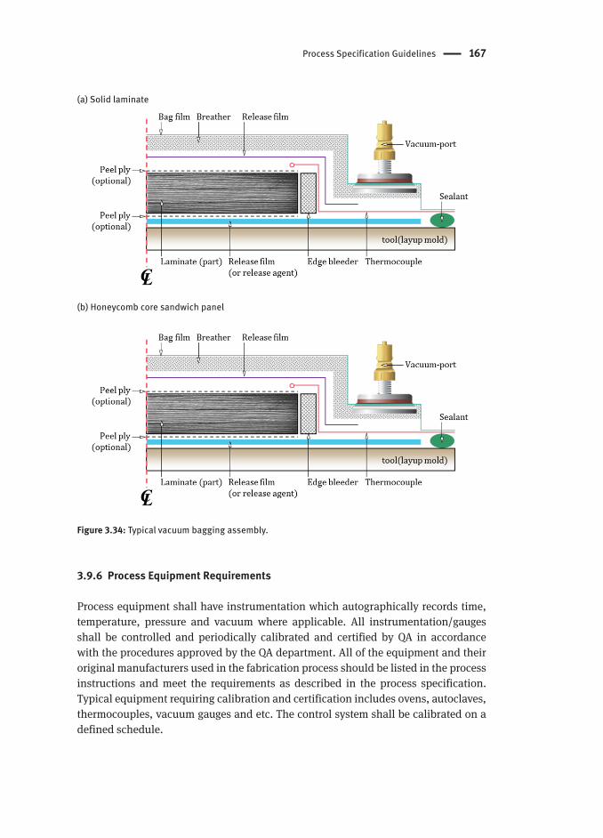
Process Specification Guidelines 167
(a) Solid laminate
(b) Honeycomb core sandwich panel
Figure 3.34: Typical vacuum bagging assembly.
3.9.6 Process Equipment Requirements
Process equipment shall have instrumentation which autographically records time, temperature, pressure and vacuum where applicable. All instrumentation/gauges shall be controlled and periodically calibrated and certified by QA in accordance with the procedures approved by the QA department. All of the equipment and their original manufacturers used in the fabrication process should be listed in the process instructions and meet the requirements as described in the process specification. Typical equipment requiring calibration and certification includes ovens, autoclaves, thermocouples, vacuum gauges and etc. The control system shall be calibrated on a defined schedule.

168 Production Control Effect on Composite Material Quality and Stability for Aerospace Usage
In general high-performance composite structures are predominantly manufactured by prepreg materials in an autoclave facility with high pressure up to 700 kPa (Kelly et al., 2001; Mouritz, 2012). It is well recorded that autoclave pressure impedes the growth of voids by less than 2% or even yields the optimized value of fiber fraction (Cano & Jensen, 2013; Abraham, 1998; Agius et al., 2013). An autoclave system allows a complex chemical reaction to occur inside a pressure vessel according to a specified time, temperature and pressure profile in order to process a variety of materials. The major elements of an autoclave system are a vessel to contain pressure, sources to heat the gas stream and circulate it uniformly within the vessel, a subsystem to pressurize the gas stream, a subsystem to apply vacuum to parts covered by a vacuum bag, a subsystem to control operating parameters and a subsystem to load the molds into the autoclave as shown in Figure 3.35.
Figure 3.35: Typical autoclave system.

Process Specification Guidelines 169
Process specifications that include autoclave cure requirements are generally not as detailed as is needed for entry into a particular autoclave. All autoclave equipment used in the fabrication of composite parts shall be complied with the requirements in the process specification through ISC (Instrument System Check) and TUS (Thermal Uniformity Survey). The temperature uniformity in the autoclave is required to be established with both full charge and no charge under all operating conditions. In order to ensure the ability of the system to achieve the maximum rate of heating and cooling, thermal insulation levels at worst-case situations, under maximum charge shall be established (Upadhya et al., 2011). An initial TUS shall be performed to measure the temperature uniformity and establish the acceptable work zone and qualified operating temperature ranges. A periodic TUS shall be performed thereafter at a frequency of 12 months or for autoclaves in accordance with AMS2750 (SAE International, 2012). Initial TUS for autoclaves shall be performed on both empty and maximum load (dummy load) in accordance with Figure 3.36.
Table 3.32: Typical deviation parameters in the vacuum bagging techniques (Vijaya et al., 2013).
Deviation Parameters Description
Improper vacuum leak test After vacuum bagging the vacuum leak rate from the bag is to be ensured before loading the part in to the autoclave for curing.
Generally the allowable leak rate is only 50 mbar for 5 minutes.
Improper placement of vacuum valves during bagging
If the vacuum valves are not placed properly on the breather then the vacuum flow will be blocked as a result white patches or the voids in the cured part.
The volatile gases will be retained in between the layers and will form defects like voids and the improper distribution of resin.
Leakage in vacuum hoses and valves
Vacuum hoses and valves that are fitted with the connectors or the plugs are properly tightened and checked before connecting it to the part to prevent leakages.
If the hoses and the valves are not fitted properly, it may read maximum vacuum initially, but at some point after application of pressure it fails abruptly causing part rejections due to defects.
Resin block in tool vacuum lines Excess resin flows in to the inbuilt vacuum lines and blocks the lines that causes defects in the cured part.
Malfunctioning of vacuum controllers and solenoid valves
Vacuum controllers fitted with autoclaves are to be calibrated periodically to ensure the uniform vacuum pressure.
Even the solenoid valves are ensured to work in auto mode for continuous supply of vacuum during the curing process in autoclaves.
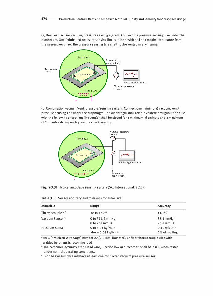
170 Production Control Effect on Composite Material Quality and Stability for Aerospace Usage
(a) Dead end sensor vacuum/pressure sensing system: Connect the pressure sensing line under the diaphragm. One (minimum) pressure sensing line is to be positioned at a maximum distance from the nearest vent line. The pressure sensing line shall not be vented in any manner.
(b) Combination vacuum/vent/pressure/sensing system: Connect one (minimum) vacuum/vent/pressure sensing line under the diaphragm. The diaphragm shall remain vented throughout the cure with the following exception: The vent(s) shall be closed for a minimum of 1minute and a maximum of 2 minutes during each pressure check reading.
Figure 3.36: Typical autoclave sensing system (SAE International, 2012).
Table 3.33: Sensor accuracy and tolerance for autoclave.
Materials Range Accuracy
Thermocouple A, B 38 to 185° C ±1.1°CVacuum Sensor C 0 to 711.2 mmHg
0 to 762 mmHg38.1mmHg25.4 mmHg
Pressure Sensor 0 to 7.03 kgf/cm2
above 7.03 kgf/cm2
0.14kgf/cm2
2% of readingA AWG (American Wire Gage) number 20 (0.8 mm diameter), or finer thermocouple wire with welded junctions is recommendedB The combined accuracy of the lead wire, junction box and recorder, shall be 2.8°C when tested under normal operating conditions.C Each bag assembly shall have at least one connected vacuum pressure sensor.

Process Specification Guidelines 171
Table 3.34: Autoclave initial qualification in accordance with AMS2750E: empty autoclave and auto-clave with dummy tests (SAE International, 2012).
Materials Empty Autoclave Autoclave with Dummy
In typical for autoclaves up to 10,000 cu. ft, position nine thermocouples.
Load the autoclave to the maximum heat-sink capacity that would occur under production conditions. The dummy load may consist of racks, tools, platens and cured or uncured scrap laminates. Heat capacity and thermal conductivity shall be similar to parts made at that facility.
Attach vacuum lines.Pressurize the autoclave to 45 ± 5 psig, perform a leak test as follows:(1) Apply full vacuum (22 inches Hg minimum).(2) Close all vacuum and vent lines.(3) Monitor line vacuum sensors for 5 minutes. The vacuum reading on each sensor shall not drop more than 5 inches in 5 minutes.Continue pressurization of autoclave to maximum qualification pressure.
Form the bag assembly using standard procedure. Use at least six thermocouples, connected to the autoclave recorder, under each bag. Each bag assembly shall contain at least one pressure sensor. The bag pressure can be measured by either of the following Figure 3.36(a) or (b). Position thermocouples within the vacuum
bags, in the autoclave, so that temperatures of structures with the greatest mass (including tool) are measured.
Pressurize the autoclave maximum qualification pressure.
Heat autoclave at approximately 10 °F/minute to desired temperature.
Within 10 minutes after the controlling thermocouple has reached the set temperature, each thermocouple shall read ± 10°F from the set temperature.
Heat the autoclave ensuring that the following are met. Minimum permissible heat-up rates calculated from lagging part thermocouple data are as described in note:
The leading part thermocouple shall not exceed a rise rate of 8°F/minute. Temperature rise rates shall be calculated for each 10 minute interval.
After the leading part thermocouple reaches 10°F from the set temperature, allow up to 60 minutes for part temperatures to equalize. Each part thermocouple shall then maintain ± 10°F from the set temperature for a minimum of 30 minutes.
Autoclave pressure shall be stable at either the maximum pressure required by the applicable processing specifications or drawings throughout the simulated cure cycle.
Pressure/temperature plots Pressure/temperature plots
The computer of these modern autoclaves is required to execute the selected cure cycle, by sequentially starting various subsystems, downloading set values at regular time intervals to the front-end controllers, acquiring, storing, and archiving data, monitoring cure status and faults, generating alarms and performing the functions of

172 Production Control Effect on Composite Material Quality and Stability for Aerospace Usage
sequential shut down and reporting (Upadhya et al., 2011; Kamalakannan & Subba, 2004; www.aschome.com). The development of high-pressure high-temperature (special operating conditions) autoclaves, on the other hand, presents itself with a completely different set of problems such as sealing at high temperatures, thermal stresses, blower shaft sealing systems, robust sensing and measurement systems that can withstand the higher operating conditions and so forth.
The process specifications also call out „thermal profiling“ of tool/parts prior to FAQ. Once the manufacturing process has been established it should not be changed unless a comparability study and necessary testing of differences has been completed. In addition, the processes should be reviewed and re-qualified if necessary, whenever any significant changes are made to the process such as sources of material, cure cycle, equipment controls, or autoclave loading patterns and tool design changes. Process capability should be demonstrated by inspection and testing as necessary to determine conformity to design requirements.
Cure Cycle : Curing is the irreversible change in the physical properties of a thermosetting resin brought about by a chemical reaction, condensation, ring closure, or addition. The processing techniques of composite laminate have found to be strongly dependent on two parameters, whatever the method of cure techniques (Grunenfelder & Nutt, 2010). The first is the outstanding glass transition temperature (Tg), a high value of which indicates an ability to achieve a full curing-state of thermoset resin. The other is the removal of voids. The resulting voids have a deleterious effect on the matrix-dominant properties such as in-plane shear strength, compressive strength, interlaminar shear strength and so forth (Grunenfelder & Nutt, 2010; Boey & Lye,1992; Hernández et al., 2011; Hernández et al., 2013). It was also reported that the voids may cause a greater susceptibility to moisture absorption and/or environmental durability (Park et al., 2010; Zhang et al., 2013; Sun, 2011). For the conventional autoclave cure the removal of voids is generally achieved by hydrostatic pressure forcing entrapped air and volatiles into the solution.
The effect of variations of cure cycle parameters on the final laminate of composite laminates is schematically shown in Figure 3.37. The initial parameters are shown at the top of the figure and the desired output at the bottom. The center area between the initial parameters and the desired outputs represents process interactions. The initial parameters used in the autoclave cure cycle can be broken down into the following categories: cure time, temperature, autoclave pressure, process materials, resin, fiber and part/tool configuration. In particular, this figure demonstrates that materials, cure process and tool are all inter-related. The changes in one cure cycle parameter may necessitate changes in another (Young, 1995).
One of the main cure cycle parameters in the autoclave cure cycle of prepreg is the cure temperature and time, including dwell(s) and heat up rates, usually control heat flow. Incorrect cure temperature may require the definition of the degree of cure for thermoset resin. For thick structures (over 25 mm thickness), heat from the resin exotherm can be dominant. It has been noted that the cure temperature affects final matrix properties

Process Specification Guidelines 173
including cure degree and the glass transition temperature, storage modulus and visco-elastic properties such as gel time and vitrification time (Kashani & Minaie, 2011). Figure 3.38 illustrates the resin viscosity behaviors (blue dot line) during cure process and the thermoset resin reaches the minimum viscosity during increasing temperature. As shown in Figure 3.38, the phase I is a critical region for curing of polymer matrix composites. Thus, the understanding of cure reaction and viscosity change at this region is vitally important to reduce void formation and achieve a uniform cured laminate thickness.
Figure 3.37: Cure factors interdependent (U.S. Department of Defense, 2002).
Figure 3.38: Typical schematic view of the changes of degree of cure and viscosity during thermosetting resins cure process. The phases of resin change according to progress the cure process: liquid state: phase I, gel state: phase II, solid state: phase III (Hubert, 1996).
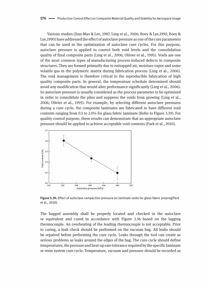
174 Production Control Effect on Composite Material Quality and Stability for Aerospace Usage
Various studies (Jian-Mao & Lee, 1987; Ling et al., 2006; Boey & Lye,1992; Boey & Lye,1990) have addressed the effect of autoclave pressure as one of the cure parameters that can be used in the optimization of autoclave cure cycles. For this purpose, autoclave pressure is applied to control both void levels and the consolidation quality of final composite parts (Ling et al., 2006; Olivier et al., 1995). Voids are one of the most common types of manufacturing process-induced defects in composite structures. They are formed primarily due to entrapped air, moisture vapor and some volatile gas in the polymeric matrix during fabrication process (Ling et al., 2006). The void management is therefore critical to the reproducible fabrication of high quality composite parts. In general, the temperature schedule determined should avoid any modification that would alter performance significantly (Ling et al., 2006).So autoclave pressure is usually considered as the process parameter to be optimized in order to consolidate the plies and suppress the voids from growing (Ling et al., 2006; Olivier et al., 1995). For example, by selecting different autoclave pressures during a cure cycle, the composite laminates are fabricated to have different void contents ranging from 0.5 to 2.0% for glass fabric laminate (Refer to Figure 3.39). For quality control purpose, these results can demonstrate that an appropriate autoclave pressure should be applied to achieve acceptable void contents (Park et al., 2010).
Figure 3.39: Effect of autoclave compaction pressure on laminate voids for glass fabric prepreg(Park et al., 2010).
The bagged assembly shall be properly located and checked in the autoclave or equivalent and cured in accordance with Figure 3.36 based on the lagging thermocouple. An overheating of the leading thermocouple is not acceptable. Prior to curing, a leak check should be performed on the vacuum bag. All leaks should be repaired before performing the cure cycle. Leaks through the tool can create as serious problems as leaks around the edges of the bag. The cure cycle should define temperatures, the pressure and heat-up rate tolerance required by the specific laminate or resin system cure cycle. Temperature, vacuum and pressure should be recorded as

Process Specification Guidelines 175
a function of time for the complete cure cycle. Typical processing parameter tolerance is summarized in Table 3.35.
Table 3.35: Typical processing parameters and their tolerances.
Cure cycle parameters Typical Application Tolerance
Temperature A Cure temperature ±5.6°CPressure Autoclave pressure during cure cycle ±34.5kPaTime Length of cure -0,+15 minutesVacuum B Vacuum level during cure cycle 67 mbarA Incorrect temperature: may require degree of cure determinationB Lost vacuum: A part is suspect and requires non-destructive inspection assessment for porosity.
Figure 3.40: Typical autoclave cure cycle.

176 Production Control Effect on Composite Material Quality and Stability for Aerospace Usage
A thermal profile should be performed after the processor‘s autoclave has been qualified to demonstrate that the heating and cooling rates and cure temperature of the part can be maintained within specification requirements. Thermal profiling requires sufficient thermocouples which are located on the tool or in the part excess to identify the leading and lagging temperature locations in the part during heating and cooling. This ensures that the heat-up rate, cure temperature, cure time and cool-down rate of all areas of the part can be maintained within specification requirements in the part during production. A permanent lagging thermocouple can be attached to the underside of the tool after thermal profile testing with multiple thermocouples which ensures that this location represents the slowest heating area of the part. The insulation around the thermocouple can be used to increase lag time. The leading thermocouple can be placed in the excess at the edge of the laminate after thermal profile testing with multiple thermocouples around the periphery of the part identifies the leading location. The effect of production parameters (resin material, tool and autoclave) on the cured parts is summarized in Table 3.36.
Table 3.36: Effect of production parameters on the cured parts.
Parameters Potential effect on cured parts
Viscosity of resin
Viscosity shall remain at lower value for a long period, assuring a greater resin flow and a more uniform compaction (Hou & Jensen, 2008). The resultant residual volatile content and residual fluidity of the epoxy resin remaining inside the composite are determined by the B-stage. The understanding of cure kinetics is essential to establishing the viability of dwell temperature as well as the effect on viscosity, which will ultimately lead to a greater understanding of void formations (refer to Figure 3.41).
Tool expansion Spring-in and warpage (refer to Figure 3.27) refers to the shape change due to the mismatch of CTE with tool material. It is reversible when the cured part is heated to the process cure temperature (Nuri et al., 2005).
Vacuum pressure
A vacuum plays a vital role during the gelation stage in the curing process, low vacuum levels may result in low interlaminar shear strength values and deficiencies in the cured part such as porosity (Vijaya et al., 2014).
Resin gels Porosity in the cured parts can be developed due to the following mechanisms: (1) entrapped air during ply collation, (2) volatiles released from the curing process, (3) dissolved gases or moisture in the resin and (4) internal stress build-up from resin cure shrinkage (Loos & Springer, 1983; Eom et al., 2001). In particular entrapped air bubbles or volatile gases should be may be collapsed or dissolved prior to resin gelation (Loos & Springer, 1983; Dave & Alfred, 1999; Brillant, 2010).
Autoclave pressure
Pressure aids in the collapse and removal of entrapped volatiles, thus reducing the void content and providing materials with high fiber volume fractions(Agius et al. 2013).
Chemical shrinkage
The chemical shrinkage of prepreg during the cure process is major contributor in the extent of process-induced warpage in composite parts. It is noted that one major contributor is the thermoset prepreg‘s anisotropy in CTE and cure shrinkage. These values along the longitudinal (i.e. parallel to the fiber axis) direction are lower than those along the transverse (perpendicular to fiber in both in-plane and out-of-plane directions). The out-of-plane anisotropy leads to process-induced warpage in composite parts with curvatures, during ramp-down from the process temperature (Kaushik & Raghavan, 2010).

Process Specification Guidelines 177
Figure 3.41: Voids from entrapped air between plies, in the resin and partially impregnated fiber bundles; enlarged view (right side) of the pressure forces acting on the air or gas bubble surface (Brillant, 2010).
Possible deviations in autoclave cure cycle : The representative deviations of KPPs in autoclave cure cycle are summarized in Table 3.37. The quality of a cured part relies on the controlled curing process and its parameters. Any deviations in these parameters result in defects and poor strength. Table 3.38 summarizes the root-cause and possible practical solution for each deviation parameter such as heating rate variation, dwell time/temperature variation, vacuum failure and drops, autoclave pressure variation and low cooling rates.
Table 3.37: Typical deviation parameters during autoclave cure cycle (Vijaya et al., 2014).
Deviation Parameters
Description
Heating rate variation
Heat-up rate can be varied between the lagging and the leading thermocouples with a thermal gradient in the range from 20 to 30°C.
The lagging thermocouple takes more time to reach the required target temperature. On the other hand, the leading thermocouple already reaches the hold/dwell state.
This deviation can result in resin degradation and in poor compaction of laminate.
Dwell time/temperature variation
The dwell temperature variation is often occur due to the pre-cooling problem in autoclave where the controller fails to maintain steady temperature during the dwell stage.
The part temperature increases continuously without maintaining the required dwell period since the air temperature gradually increases during the process.
The heating rate variation between the lagging and the leading thermocouples also leads to the improper dwell time and thermal gradient variations. The leading thermocouple already completes 20 - 30 minutes dwell before the lagging thermocouple reaches the dwell point.
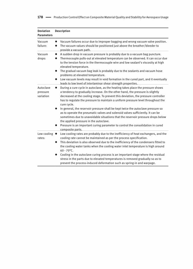
178 Production Control Effect on Composite Material Quality and Stability for Aerospace Usage
Deviation Parameters
Description
Vacuumfailure:
Vacuum failures occur due to improper bagging and wrong vacuum valve position. The vacuum values should be positioned just above the breather/bleeder to
provide a vacuum path.Vacuumdrops:
A sudden drop in vacuum pressure is probably due to a vacuum bag puncture. Thermocouple pulls-out at elevated temperature can be observed. It can occur due
to the tension force in the thermocouple wire and low sealant‘s viscosity at high elevated temperature.
The gradual vacuum bag leak is probably due to the sealants and vacuum hose problems at elevated temperature.
Low vacuum levels may result in void formation in the cured part, and it eventually leads to low level of interlaminar shear strength properties.
Autoclave pressurevariation
During a cure cycle in autoclave, as the heating takes place the pressure shows a tendency to gradually increase. On the other hand, the pressure is slightly decreased at the cooling stage. To prevent this deviation, the pressure controller has to regulate the pressure to maintain a uniform pressure level throughout the cure cycle.
In general, the reservoir pressure shall be kept twice the autoclave pressure so as to operate the pneumatic valves and solenoid valves sufficiently. It can be sometimes due to unavoidable situations that the reservoir pressure drops below the applied pressure in the autoclave.
Pressure is an important curing parameter to control the consolidation in cured composite parts.
Low cooling rates:
Low cooling rates are probably due to the inefficiency of heat exchangers, and the cooling rate cannot be maintained as per the process specification.
This deviation is also observed due to the inefficiency of the condensers fitted to the cooling water tanks when the cooling water inlet temperature is high around 60 - 70°C.
Cooling in the autoclave curing process is an important stage where the residual stress in the parts due to elevated temperatures is removed gradually so as to prevent the process-induced deformation such as spring-in and warpage.
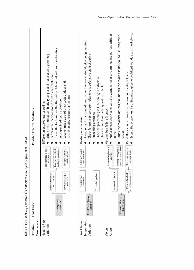
Process Specification Guidelines 179
Tabl
e 3.
38: L
ist o
f key
dev
iatio
ns in
aut
ocla
ve cu
re cy
cle
(Vija
ya e
t al.,
201
4).
Devi
atio
n Pa
ram
eter
sRo
ot-C
ause
Poss
ible
Pra
ctic
al S
olut
ions
Heat
ing
Rate
Va
riatio
nDi
ffere
nt m
etal
tool
-par
ts cu
ring:
St
udy
the
ther
mal
cond
uctiv
ity a
s pe
r too
l mat
eria
l and
geo
met
ry Pe
rform
the
ther
mal
pro
file
test
s as
per
eac
h to
ol Gr
oup
the
tool
s as
per
the
ther
mal
pro
file
repo
rt w
ith u
nifo
rm h
eatin
g Im
prop
er lo
adin
g in
aut
ocla
ve:
Lo
cate
larg
e si
ze a
nd th
ick
tool
s at
doo
r end
Lo
cate
sm
all s
ize
tool
s at
fan
end
Dwel
l Tim
e/Te
mpe
ratu
re
Varia
tion
Heat
ing
rate
varia
tion:
Gr
oupi
ng a
nd m
appi
ng o
f too
ls a
s pe
r the
tool
mat
eria
l, si
ze a
nd g
eom
etry
Ch
eck
for p
rogr
am a
nd co
ntro
ller e
rrors
bef
ore
the
star
t of c
urin
g Pr
ecoo
ling
prob
lem
: Ch
eck
for p
reco
olin
g is
func
tioni
ng in
aut
ocla
ve Ch
eck
for i
nlet
wat
er te
mpe
ratu
re in
tank
Vacu
umFa
ilure
Vacu
um b
ag fa
ilure
(bur
st):
Pr
efor
m le
ak ch
eck
to e
nsur
e th
e va
cuum
hos
es a
nd co
nnec
ting
part
are
with
out
defe
ct St
udy
the
tool
his
tory
card
and
dis
card
the
tool
if a
leak
is fo
und
(i.e.
com
posi
te
tool
s)Re
set t
he va
cuum
line
s in
aut
ocla
ve b
efor
e st
art o
f cur
e. En
sure
the
prop
er le
ngth
of t
herm
ocou
ples
to a
void
pul
l out
due
to a
ir tu
rbul
ence
.
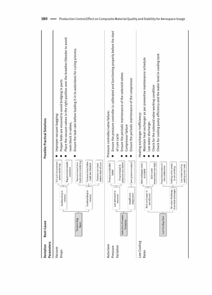
180 Production Control Effect on Composite Material Quality and Stability for Aerospace Usage
Devi
atio
n Pa
ram
eter
sRo
ot-C
ause
Poss
ible
Pra
ctic
al S
olut
ions
Vacu
umDr
ops
Im
prop
er va
cuum
bag
ging
: Pr
oper
fold
s ar
e en
sure
d to
avo
id b
ridgi
ng in
par
ts Pl
ace
the
vacu
um va
lves
in th
e rig
ht p
ositi
on o
ver t
he b
reat
her/
blee
der t
o av
oid
resi
n bl
ock
in va
lves
. En
sure
the
leak
rate
bef
ore
load
ing
it in
to a
utoc
lave
s fo
r cur
ing
proc
ess.
Auto
clav
e Pr
essu
re
Varia
tion
Pres
sure
cont
rolle
r/va
lve
failu
re:
En
sure
the
pres
sure
cont
rolle
r is
calib
rate
d an
d fu
nctio
ning
pro
perly
bef
ore
the
star
t of
cure
cycl
e En
sure
the
perio
dic m
aint
enan
ce o
f the
sol
enoi
d va
lves
Co
mpr
esso
r fai
lure
En
sure
the
perio
dic m
aint
enan
ce o
f the
com
pres
sor
Low
Coo
ling
Rate
sHe
atin
g ex
chan
ger i
neffi
cien
cy:
M
aint
ain
heat
exc
hang
er a
s pe
r pre
vent
ive
mai
nten
ance
sch
edul
e Lo
w w
ater
dis
char
ge:
Ch
eck
for t
he s
olen
oid
valv
e w
orki
ng co
nditi
on Ch
eck
for c
oolin
g pu
mp
effic
ienc
y an
d th
e w
ater
leve
l in
cool
ing
tank

Monitoring Procedures 181
Devi
atio
n Pa
ram
eter
sRo
ot-C
ause
Poss
ible
Pra
ctic
al S
olut
ions
Vacu
umDr
ops
Im
prop
er va
cuum
bag
ging
: Pr
oper
fold
s ar
e en
sure
d to
avo
id b
ridgi
ng in
par
ts Pl
ace
the
vacu
um va
lves
in th
e rig
ht p
ositi
on o
ver t
he b
reat
her/
blee
der t
o av
oid
resi
n bl
ock
in va
lves
. En
sure
the
leak
rate
bef
ore
load
ing
it in
to a
utoc
lave
s fo
r cur
ing
proc
ess.
Auto
clav
e Pr
essu
re
Varia
tion
Pres
sure
cont
rolle
r/va
lve
failu
re:
En
sure
the
pres
sure
cont
rolle
r is
calib
rate
d an
d fu
nctio
ning
pro
perly
bef
ore
the
star
t of
cure
cycl
e En
sure
the
perio
dic m
aint
enan
ce o
f the
sol
enoi
d va
lves
Co
mpr
esso
r fai
lure
En
sure
the
perio
dic m
aint
enan
ce o
f the
com
pres
sor
Low
Coo
ling
Rate
sHe
atin
g ex
chan
ger i
neffi
cien
cy:
M
aint
ain
heat
exc
hang
er a
s pe
r pre
vent
ive
mai
nten
ance
sch
edul
e Lo
w w
ater
dis
char
ge:
Ch
eck
for t
he s
olen
oid
valv
e w
orki
ng co
nditi
on Ch
eck
for c
oolin
g pu
mp
effic
ienc
y an
d th
e w
ater
leve
l in
cool
ing
tank
3.10 Monitoring Procedures
QCs shall verify that the requirements of process specification are met by monitoring the process and evaluating conditions in accordance with established QA provisions. The following areas should be reviewed and monitoring procedures instituted.1. Materials: QCs shall verify that all materials which are incorporated into the part
fabrication are handled per their respective material and process specifications. The material accountability and handling system shall be monitored to ensure continuous controls (i.e. shelf life, temperature and humidity) from receiving through storage and production. The consumable materials (i.e. vacuum bag, release film, breather/bleeder and so forth) used during part manufacturing shall comply with the applicable requirements.
2. Process equipment: All process equipment, such as freezers, curing and drying ovens and autoclaves shall have instrumentation which autographically or digitally records time, temperature, pressure and vacuum parameters where applicable. All instrumentation and gauges shall be calibrated at periodic intervals. QA shall maintain all test equipment within pre-established accuracy requirements through a system of periodic calibrations in conformance with MIL-C-45662 (U.S. Department of Defense, 1980) and ISO 10012-1 (ISO, 1999b). In particular, autoclave equipment shall be capable of maintaining the part to be cured and its associated tool within the temperature range, pressure and heat up rate tolerances required by the process specification.
3. Tool: Tools shall be identified and traceable to the corresponding engineering part numbers. Tools shall be free from damage, deterioration or debris that would adversely affect the part. For this purpose, all tool surfaces shall be inspected after every autoclave cure cycle to ensure excessive resin build up does not exist. An additional thermal profile (i.e. cure temperature survey) experiment is required to ensure cure temperature uniformity during a cure cycle.
4. Facility Survey: Survey team reviews the facility for at least the following items to determine the adequacy of the facility to produce satisfactory parts:– All facility and equipment items– QA procedures, calibrations and records– Material kitting areas and identification– Layout of entire fabrication area and cleanliness control– Tool preparation, release agent segregation area, core machining area and
fabrication area.– Receiving inspection and final inspection procedures including test
equipment certifications and any tool fixtures required to perform inspections5. Third party standard certifications, for example Aerospace Standards and NADCAP.6. Test specification and method: All test methods specified within the process
specification should be listed. The preferred practice is to reference industry test method specifications or standards such as those published by ASTM. Exceptions to standard methods should be clearly documented.

182 Production Control Effect on Composite Material Quality and Stability for Aerospace Usage
3.11 Nonconforming Part
Nonconformance means (1) failure of a part to comply with the requirements of the engineering drawing, specification, or (2) a part having defects which affect form, fit, function, weight, interchangeability and reliability or safety. Typically nonconformance should be submitted to the MRB4 (Material Review Board) group (U.S. Department of Transportation, 2004). Design deviations should be incorporated into the drawing as a „one part only“ or the drawings should be revised to mirror the part configuration. The method of correcting or resolving a deficiency must conform to one of three disposition classifications: „Rework“, „Repair“, or „Use As Is“:
– Rework: A procedure applied to a nonconformance that will completely eliminate it and result in a characteristic that conforms completely to the drawing, specification, or contract requirements
– Repair: A procedure which reduces but will not completely eliminate a non conformance and which has been reviewed and concurred in by the MRB and approved for use by the customer. The purpose of repair is to reduce the effect of the nonconformance. Repair is distinguished from rework in that the characteristic after repair still does not completely conform to the applicable drawings, specifications, or contract requirements.
– Use As Is: A disposition of material with one or more minor non-conformances determined to be useable for its intended purpose in its existing condition.
For composite parts, the representative processing anomalies such as voids, delamination and porosity can occur during the cure process and may be the result of poor tool, insufficient ply consolidation, low autoclave pressure, loss of vacuum, or nonconforming material (e.g. improper resin content or formulation). The typical defect types are described in the next section.
3.12 Types of Defects
In composite parts, many variables in the manufacturing process make different types of defects or discrepancy possible. Figure 3.43 shows the composite design criteria for structural robustness and material processing can significantly impact the structural performance of composite material. While these baseline processes were initially used in the fabrication of test coupons and test elements, process development was an ongoing activity. In addition, this process evolution was driven by design changes, manufacturing constraints, or to solve process issues (i.e. process anomalies).
4 A board consisting of technically qualified and authorized representatives of a Boeing supplier who determine the proper disposition of Nonconforming Material referred to them.

Types of Defects 183
It is required that process anomalies allowed per the process specifications will not grow for the equivalent of more than two design service lives. Therefore the process anomalies and their acceptable limits and rework limit and procedures shall be defined in the process specification. Any discrepancies that exceeds the acceptance limits shall be rejected and identified based on the nonconformance procedures (refer to Figure 3.42).
Figure 3.42: Typical procedures for FAI and nonconformance part.
BVID: Small damages which may not be found during heavy maintenance general visual inspections using typical lighting conditions from a distance of five (5) feet
Figure 3.43: Composite design criteria for structural robustness: Stress and strain reduction of composite materials in accordance with defect and damage types (Jian-Mao& Lee, 1987).

184 Production Control Effect on Composite Material Quality and Stability for Aerospace Usage
For finding the process induced anomalies, a visual inspection with 10x or greater magnification is generally employed to verify the discrepancy condition. Visual inspection, as a minimum, is also required after rework has been completed. Any discrepancies that have been detected using instrumental non-destructive inspection shall be re-inspected after rework has been completed using instrumental non-destructive inspection to verify the discrepancy has been eliminated. Defects that generally are of most concern are delamination and voids. Both of them are gaps in the structural parts, which depending on location, can dramatically reduce strength. A survey by NASA‘s Aircraft Energy Efficiency (ACEE) program on the Boeing 737 commercial transport development was undertaken to obtain data concerning the structural nonconforming part records for 374 discrepant parts as shown in Figure 3.44 (Aniversario et al., 1983). 50% of defects associated with surface discrepancies were recorded, for example resin starvation and scratches. The distribution over the defect types was in the order of 50% surface discrepancies > 32% dimensional discrepancies > 14% process failures > 4% miscellaneous. Table 3.39 summarizes the effect of defects in the structural composite parts.
Figure 3.44: Structural nonconforming part records for Boeing 737 composite stabilizer (Aniversario et al., 1983).
Table 3.39: Potential effect on structural performance for solid laminate.
Discrepancy Potential effect on structural performance
Delamination Catastrophic failure due to loss of interlaminar shear strength. Typical acceptance criteria require the detection of delamination with a linear dimension larger than 6.4 mm.
Voids Degrades matrix-dominated properties. 1% porosity reduces strength by 5% and fatigue life by 50%.
Ply gap Strength degradation depends on stacking order and location. For [0/45/90/±45]2S laminate, strength is reduced 9% due to gap(s) in 0 ply and 17% due to gap(s) in 90ply.
Ply waviness For 0 ply waviness in [0/45/90/±45]2S laminate, static strength reduction is 10% for slight waviness and 25% for extreme waviness. Fatigue life is reduced at least by a factor of 10.
Scratched surfaces (i.e. sharp, narrow cuts or marks)
Static strength reduction of up to 50%. Strength reduction is small for notch sizes that are expected in service.

Types of Defects 185
Acceptance criteria for solid laminate for representative defects are summarized in Table 3.40.
Table 3.40: Acceptance criteria for solid laminate.
Discrepancy Definition Acceptable Limits
Voids(see Figure 3.45(b))
Relatively large localized air, water vapor or gas that have been trapped and cured into a laminate (Refer to Figure 3.46)
Maximum dimension not to exceed 13 mm in any direction.
Inclusions(see Figure 3.45(c))
Visible foreign material such as particles, chips and films (Refer to Figure 3.47)
Single discrepancies: Maximum area not to exceed 161 mm2.Multiple discrepancies: Maximum area not to exceed 22 mm in any direction and the distance between inclusions shall be greater than 152 mm.
Surface depressions(see Figure 3.45(d))
A localized indentation or low spot in a surface
For faying surface area, all width for depth shall be less than 0.13 mm and depression length shall be not greater than 152 mm.Depression depth shall be less than 25% of total laminate thickness.No visible fiber damage is allowed.
Scratched surfaces (i.e. sharp, narrow cuts or marks)(see Figure 3.45(e))
Scratches are allowed in the surface resin provided no fiber damage exists (i.e. no penetration into fiber)
Ply wrinkles or folds(see Figure 3.45(f))
A ridge or fold-over of ply material
No visible ply wrinkles are allowed.
Ply gap(see Figure 3.45(g))
Ply splicing shall be minimized and any gap is not allowed.Butt splicing with a maximum gap of 0.0 to 1.5 mm.
Resin starved area(see Figure 3.45(h))
Area of a composite where the resin has a non-continuous coverage of the fiber.
Any surface resin starvation where no visible fibers are exposed (i.e. limited to the surface ply).Resin starved area shall be less than 5% of total laminate area.
Delamination(see Figure 3.45(i))
Separation of laminate plies from each other (Refer to Figure 3.47)
Single discrepancies: Maximum dimension not to exceed 13 mm in any direction.Multiple discrepancies: For discrepancies exceeding 6.3 mm in length, the distance between delamination and voids shall be greater than 63 mm.

186 Production Control Effect on Composite Material Quality and Stability for Aerospace Usage
Figure 3.45: Typical defect types for solid laminate.
Figure 3.46: Void area formed in unidirectional carbon laminate.
Figure 3.47: Inclusion inserted in unidirectional carbon laminate.
Acceptance criteria for honeycomb core sandwich panel for representative defects are summarized in Table 3.41.
Table 3.41: Acceptance criteria for honeycomb core sandwich panels.
Discrepancy Definition Acceptable Limits
Cell tear-out(see Figure 3.48(a))
161 mm2 max area or 13 mm max width from edge.
Core splice(see Figure 3.48(b))Node bond separation(see Figure 3.48(c))
Nodes that come apart after being bonded together by node adhesive.
Number of nodes: <10% partial and <1% total separation
Frayed or burred areas(see Figure 3.48(f))
Broken or loose fibers occurring at machined edges or holes
No fiber fuzz after sanding
Edge waviness Within 1.3 mm of nominal core edgeCore depression Core depression is a localized
indentation or gouge in the core.0.5 mm deep, 13 mm long

Conclusions 187
Figure 3.48: Typical defect types for honeycomb core sandwich panel.
3.13 Conclusions
Composite materials should be considered as unique materials in the design and manufacturing process because material, facilities, equipment, tooling, ply collation and in-process controls have a pronounced effect on structural design. Conscientious adherence to proven concurrent engineering principles and careful design and material selection guidelines in the design, manufacture, in-process controls and inspection of aerospace composites can lead to a high level of structural product integrity consistent with design requirements. This can be accomplished by planning, engineering, manufacturing and the QA department.
This chapter has dealt with the details of available standard practices and procedures for composite material qualification applied to composite structures. Early experiences have revealed that material qualification is the single most critical step, since it is fundamental to ensure continued airworthiness. Thus, all qualification
188 Production Control Effect on Composite Material Quality and Stability for Aerospace Usage
standards and technical issues regarding with material QCs should be clearly defined prior to a part qualification. The previous discussion has highlighted current material qualification methodologies for composite structure for aircraft usage. Whether at M&P qualification, or at structural design, both certification approaches show the need for an extensive testing database and inspection results for the assessment of complex interactions, constituent materials (i.e. fiber, resin), un-cured prepreg and cured lamina/laminate properties and a process used for production of composite structure. Consequently, it is essential that the material and processing variability of composite structures should be considered in static strength substantiation. This is primarily achieved by establishing sufficient processes and QCs to produce a composite part and reliably substantiate the required strength by test and analysis.
Finally, aerospace-grade composite parts will embrace more noninvasive methods of in- process validation and verification of material properties. For this purpose, QCs during composite part manufacturing is essential if the structural, dimensional and durability performances designed into a part are to be consistently achieved. In the aerospace industry, it is typically based on governmental standards, the company‘s own process specifications and quality assurance requirements. For this purpose, all available resources such as material, facilities, equipment, tooling, ply collation, level of personnel training and documentation system should meet the design criteria.
ReferencesAbraham, D., Matthews, S., & McIlhagger, R. (1998). A comparison of physical properties of glass
fibre epoxy composites produced by wet lay-up with autoclave consolidation and resin transfer moulding. Composite Part A-Applied Science and Manufacturing, 29(7), 795-801.
Abumeri, G., Abdi, F., Raju, K. S. et al. (2011). Cost effective computational approach for generation of polymeric composite material allowables for reduced testing. In Brahim, A. (Ed.), Advances in Composite Materials - Ecodesign and Analysis: InTech (DOI: 10.5772/14528).
Agius, S. L., Magniez, K. J. C., & Fox, B. L. (2013). Cure behaviour and void development within rapidly cured out-of-autoclave composites. Composites Part B: Engineering, 47, 230-237.
Aniversario, R. B., Harvey, S. T., & McCarty, J. E. et al. (1983). Design, ancillary testing, analysis, and fabrication data for the advanced composite stabilizer for Boeing 737 aircraft. Washington, DC: National Aeronautics and Space Administration.
Alderliesten, R. C. (2007). Damage tolerance of bonded aircraft structures. The Netherlands: First International Conference on Damage Tolerance of Aircraft Structures (DTAS 2007).
Alderliesten, R. C. (2009). Damage tolerance of bonded aircraft structures. International Journal of Fatigue, 31 (6), 1024-1030.
Allen, J. F.,& Gary, D. O. Boeing Composite Airframe Damage Tolerance and service Experience (available at www.servidor-da.aero.upm.es).
Arthasartsri, S., & Ren, H. (2009). Validation and verification methodologies in A380 aircraft reliability program. Piscataway: The 8th International Conference on Reliability, Maintainability and Safety ICRMS.
Ashraf, U. A. (2006). Resin flow velocity measurement of carbon fiber/epoxy composites in autoclave processing: Master Thesis. Wichita State University.

References 189
Beumler, T. H.(2009). Fiber metal laminate structures-from laboratory to application. Lecture to RAeS, DGLR & VDI, Hamburg.
Blom, A. W. (2010). Structural performance of fiber-placed, variable-stiffness composite conical and cylindrical shells: Ph. D. Dissertation. The Netherlands: Delft University of Technology.
Boeing Commercial Airplanes. (2010). Composite manufacturing and quality control (available atwww.niar.wichita.edu)
Boey, F. Y. C.,& Lye, S. W. (1990). Effects of vacuum and pressure in an autoclave curing process for a thermosetting fibre-reinforced composite. Journal of Materials Processing Technology, 23 (2), 121-131.
Boey, F. Y. C., & Lye, S. W. (1992). Void reduction in autoclave processing of thermoset composites: part 1: high pressure effects on void reduction. Composites, 23(4), 261-265.
Bogucki, G., McCarvill, W., & Ward, S., et al.(2003). Guidelines for the development of process specifications. instructions and controls for the fabrication of fiber-reinforced polymer composites(DOT/FAA/AR-02/110). Washington, DC: U.S. Department of Transportation, Federal Aviation Administration.
Brillant, M. (2010). Out-of-autoclave manufacturing of complex shape composite laminates: Master Thesis. Canada: McGill University.
Campbel, F. C. (2003). Manufacturing processes for advanced composites. Amsterdam: Elsevier.Cano, R. J., & Jensen, B. J. (2013). Out of the autoclave fabrication of LaRCTM PETI-9 polyimide
laminates.Long Beach, CA: 2013 SAMPE Technical Conference And Exhibition.Chady, T.(2013). AIRBUS versus BOEING-composite materials: The sky’s the limit. (Le Mauricien.com)Code of Federal Regulations-Part 25 Airworthiness Standards: Transport Category Airplanes(rgl.faa.
gov)Code of Federal Regulations-Part 21 Airworthiness Standards: Certification Procedures for Products
and Parts(rgl.faa.gov)Code of Federal Regulations-14 CFR 21.125-Production inspection system: Materials Review
Board(rgl.faa.gov)Code of Federal Regulations-14 CFR 21.93-Classification of Changes in Type Design(rgl.faa.gov)Code of Federal Regulations-14 CFR 21.95-Approval of Minor ChangesinType Design(rgl.faa.gov)Code of Federal Regulations-14 CFR 21.97-Approval of Major Changes in Type Design(rgl.faa.gov)Compositeworld.(2014). Tooling (available at www.compositesworld.com/articles/tooling).Compositesworld. (2014). Fabrication Methods (available at www.compositesworld.com/blog/post/
fabrication-methods).Cytec Industrial Materials.(2013). Autoclave processing-lay-up and bagging guidelines (available at
www.cytec.com).DaveÂ, R. S., & Alfred, C. Loos. (1999). Processing of Composites Vol 1. In Kardos, J. L. (Ed.), Void
Growth and Disccolution (pp. 182-207). Munich: Hanser Publishing.Davies, C. R. (2003). Composite material control-FAA efforts. Chicago: in 2002, 2nd FAA Workshop on
Composite Material Control.Dexter, H. B., & Baker, D. J. (1994). Flight service environmental effects on composite materials and
structures. Advanced Performance Materials, 1 (1), 51-85.Eom, Y., Boogh, L., & Michaud, V. et al. (2001). A structure and property based process window for
void free thermoset composites. Polymer Composites, 22 (1), 22-31.FAA Order 8120.22. (2013). Production Approval Procedures(rgl.faa.gov)FAA Order 8120.23. (2013). Certificate Management of Production Approval Holders(rgl.faa.gov)FAI-Engineering Compliance (available at www.sirs.co.uk)Fawcett, A., Trostle, J., & Ward, S. (1997). 777 Empennage certification approach. Melbourne,
Australia: 11th International Conference for Composite Materials.Ferabol, P. (2009). Composite materials strength determination within the current certification
methodology for aircraft structures. Journal of Aircraft, 46 (4), 1365-1374.

190 Production Control Effect on Composite Material Quality and Stability for Aerospace Usage
Gibson, W., & Morrell, P.(2004). Theory and practice in aircraft financial evaluation. Journal of Air Transport Management, 10 (6), 427-433.
Ginger, G. (2011). A350 XWB update: Smart manufacturing. High-Performance Composites. 9.Goranson, U.G. (1998). Fatigue Issues in aircraft maintenance and repairs. International Journal of
Fatigue, 20(6), 413-431.Grover, A. H. III. (2001). Introduction to Quality Assurance. In Daniel, B. M.& Steven L. D. (Eds.),
HANDBOOK, A. S. M. Volume 21: Composites. American Society of Metals. International Handbook Committee.
Grunenfelder, L. K., & Nutt, S. R. (2010). Void formation in composite prepregs-effect of dissolved moisture. Composite Science Technology, 70(16), 2304-2309.
Gurit AG. (2013). Guide of vacuum consumables (available at www.gurit.com).Hernández, S., Sket, F., &Molina-Aldareguı´a, J. M. et al. (2011). Effect of curing cycle on void
distribution and interlaminar shear strength in polymer-matrix composites. Composite Science Technology, 71(10), 1331-1341.
Hernández, S., Sket, F., & González, C. et al.(2013). Optimization of curing cycle in carbon fiber-reinforced laminates: void distribution and mechanical properties. Composite Science and Technology, 85(21), 73-82.
Hexcel Corporation. (2013). HexPly® prepreg technology (available at www.hexcel.com).Hou, T. H.,& Jensen. (2008). Double-vacuum-bag technology for volatile management in composite
fabrication. Polymer Composites, 29 (8), 906-914.Hubert, P. (1996). Aspects of flow and compaction of laminated composite shapes during cure: Ph. D.
Dissertation. University of British Columbia.Ilcewicz, L., & Murphy, B. (2005). Safety and certification initiatives for composite airframe structure.
Texas: 46th AIAA/ASME/ASCE/AHS/ASC Structures, Structural Dynamics and Materials Conference.
Ilcewicz, L. (2011). FAA composite safety and certification initiatives (with emphasis on support from JAMS research and development). Seattle, WA: FAA JAMS 2010 Technical Review Meeting.
ISO. (1999). Cleanrooms and associated controlled environments–Part 1: Classification of air cleanliness (ISO, EN. 14644-1).
ISO. (1999). Quality Assurance Requirements for Measuring Equipment-Part 1: Metrological Confirmation System for Measuring Equipment (ISO, 10012).
Jedidi, J., Jacquemin, F., & Vautrin, A. (2006). accelerated hygrothermal cyclical tests for carbon/epoxy laminates. Composites Part A: Applied Science and Manufacturing, 37 (4), 636-645.
Jérôme, P.(2001). Composite materials in the Airbus A380-from history to future. Beijing: Proceedings 13th International Conference on Composite Materials (ICCM-13).
Jian-Mao, T.,& Lee, W. I. (1987). Effects of cure pressure on resin flow, voids, and mechanical properties. Journal of Composite Materials. 21 (5), 421-440.
John, S. T., Yeow, N., & Clarkson, B., et al. (2008). Production control effect on composite material quality and stability.Everett, WA: FAA JAMS 2008 Technical Review Meeting.
Kamalakannan, G. M., & Subba, R. M.(2004). Development of a computer based process control system for an autoclave to cure polymer matrix composites. Pune, India: Proceedings of the International Conference on Instrumentation.
Kashani, P., & Minaie,B. (2011). An ex-situ state-based approach using rheological properties to measure and model cure in polymer composites. Journal of Reinforced Plastics and Composites, 30, 121-133.
Kaushik, V., & Raghavan, J. (2010). Experimental study of tool-part interaction during autoclave processing of thermoset polymer composite structures. Composites Part A: Applied Science and Manufacturing, 41 (9), 1210-1218.

References 191
Kelly, D. W., Li, R., & Willgoss, R. (2001). Precision fibre placement to improve strength and stiffness: a design and manufacturing solution. Sydney: Processings of the ACUN-3 International Composites Conference Technology.
Lee, H. S.,& Min, K. J. (2007). Advanced methodology of composite materials qualification for small aircraft. Journal of The Korean Society for Aeronautical and Space Science 35 (2), 446-451.
Lee, H. S. (2006). Material qualification, equivalency and acceptance test for aerospace composite materials. Journal of the Korean Society for Composite Materials, 19 (2), 1-6.
Lin, Y., Ye, L., & Zhongqing, S., et al. (2005). Functionalized composite structures for new generation airframes: a review. Composites Science and Technology, 65 (9), 1436-1446.
Ling, L., Zhang, B. M.,& Wang, D. F. et al. (2006). Effects of cure cycles on void content and mechanical properties of composite laminates. Composite Structures, 73 (3), 303-309.
Loos, A. C.,& Springer, G. S. (1983). Curing of epoxy matrix composites. Journal of Composite Materials, 17 (2), 135-169.
Marsh, G.(2008). Airbus takes on Boeing with composite A350 XWB. Reinforced Plastics, 5. (available at www.materialstoday.com)
Marsh, G. (2005). Airframers exploit composites in battle for supremacy. Reinforced Plastics, 49 (3), 26-32.
Matthew, M. T., Babu, J., & John, L. K. (1997). Experimental characterization of autoclave-cured glass-epoxy composite laminates: cure cycle effects upon thickness, void content, and related phenomena. Polymer Composites,18 (3), 283-299.
McCarvill, W., Ward, S., & Bogucki, G. et al.(2003). Guidelines and recommended criteria for the development of a material specification for carbon fiber/epoxy unidirectional prepregs(DOT/FAA/AR-02/109).Washington, DC: U.S. Department of Transportation, Federal Aviation Adminis-tration.
Mohaghegh, M.(2005). Validation and certification of aircraft structures. Texas: 46th AIAA/ASME/ASCE/AHS/ASC Structures, Structural Dynamics and Materials Conference. 2005-2162.
Mohammad, H. H. (2013). Effects of out-time on cure kinetics and rheological properties of out-of-autoclave and autoclave prepregs: Master Thesis. Wichita State University.
Mouritz, A. P. (2012). Manufacturing of fibre-polymer composite materials. InMouritz, A. P. (Ed.), Introduction to Aerospace Materials (pp. 303-337). Cambridge, UK: Woodhead Publishing.
Muchiri, A. K.(2002). Maintenance planning optimization for the Boeing 737 next generation aircraft: Master Thesis. The Netherlands: Delft University of Technology.
Ng, Y.,& Tomblin, J. (2008). Prepreg Process Control Document(PCD) preparation and maintenance guide (Document No.: NRP 101). NIAR.
Niu, M. C. Y. (1992). Composite airframe structures. Hong Kong: Hong Kong Conmilit Press Limited.Nuri, E.,& Kevin, P., &Michael, R. W. et al.(2005). Development of spring-in angle during cure
of a thermosetting composite. Composites Part A: Applied Science and Manufacturing,36 (12),1700-1706.
Nuri, E., Kevin, P., & Michael, R. W. et al. (2005). An experimental method to study the frictional processes during composites manufacturing. Composites Part A: Applied Science and Manufacturing, 36 (11), 1536-1544.
Olivier, P., Cottu, J. P., & Ferret, B. (1995). Effects of cure cycle pressure and voids on some mechanical properties of carbon/epoxy laminates. composites, 26(7), 509-15.
Park, S. Y., Choi, W. J., & Choi, H. S. (2010). The effects of void contents on the long-term hygrothermal behaviors of glass/epoxy and GLARE Laminates. Composite Structures, 92(1), 18-24.
Reichl, M. (2007). Composites meet aviation requirements. Reinforced Plastics, 51 (6), 38-40.Rohwer, K., Kappel, E., & Stefaniak, D. et al. (2013). Spring-in and warpage-progress in simulating
manufacturing aspects. Mechanics of Composite Materials,49 (2),193-200.

192 Production Control Effect on Composite Material Quality and Stability for Aerospace Usage
Rosa, D. (2007). Boeing versus Airbus competing metal to composite focus. Omnexus, 1. (available at www.omnexus.specialchem.com)
SAE International. (2000). Aerospace First Article Inspection Requirement.SAE International. (2004). Nadcap Requirements for Composites (AS7118).SAE International. (2012). Pyrometry (AMS2750).Seneviratne, W. P., & Tomblin, J. S.(2012). Environmental compensation factor influence on
composite design and certification. Baltimore: FAA JAMS 2012 Technical Review Meeting.Smith, P. J., Thomson, L. W.,& Wilson, R. D. (1986). Development of pressure containment and
damage tolerance technology for composite fuselage structures in large transport aircraft. Washington, DC: National Aeronautics and Space Administration.
Soutis C.(2005). Carbon Fiber Reinforced plastics in aircraft construction. Material Science Engineering: A, 412 (1-2); 171-176.
Starnes, J. H.(2005). Strength degradation prediction methods and damage science for aging airframe structures. Washington, DC: National Aeronautics and Space Administration.
Sun, P., Zhao, Y., & Luo, Y. et al.(2011). Effect of temperature and cyclic hygrothermal aging on the interlaminar shear strength of carbon fiber/bismaleimide (BMI) composite. Materials & Design, 32(8-9), 4341-4347.
Tavakol, B. (2011). Prediction of residual stresses and distortion of carbon fiber/epoxy composites due to curing process: Master of Science. Wichita State University.
Tavakol, B., Roozbehjavan, P., & Ahmed, A. et al. (2003). Prediction of residual stresses and distortion in carbon fiber-epoxy composite parts due to curing process using finite element analysis.Journal of Applied Polymer Science, 128 (2), 941-950.
Tomblin, J. S., Ng, Y. C.,& Raju, K. S. (2003). Material Qualification and equivalency for polymer matrix composite material systems: Updated Procedure(DOT/FAA/AR-03/19). Washington, DC: U.S. Department of Transportation, Federal Aviation Administration.
Tomblin, J. S., Ng, Y, C., & Raju, K, S. (2001). Material Qualification and equivalency for polymer matrix composite material systems(DOT/FAA/AR-00/47).Washington, DC: U.S. Department of Transportation, Federal Aviation Administration.
Upadhya, A. R., Dayananda, G. N.,& Kamalakannan, G. M. et al.(2011). Autoclaves for aerospace applications: issues and challenges. International Journal of Aerospace Engineering,2011.
U.S. Department of Transportation. (2009). Advisory Circular(AC No.: 20-107B), Composite Aircraft Structure. Washington, DC: Federal Aviation Administration.
U.S. Department of Transportation. (2009). Advisory Circular (AC No.: 21-43), Issuance of Production Approvals Under Subparts G, K, & O. Washington, DC: Federal Aviation Administration.
U.S. Department of Defense. (2002). Composite materials handbook-Volume 3. Polymer matrix composites materials usage. design and analysis. Washington, DC.
U.S. Department of Transportation. (1989). Advisory Circular(AC No.: 21-26 Quality Control for the Manufacture of Composite Structures. Federal Aviation Administration. Washington, DC.
U.S. Department of Transportation. (2008). Military Standard: Defense and PRogram-Unique Specifi-cations Format and Content (MIL-STD-961E). Washington, DC.
U.S. Department of Defense. (1980). Military Standard: Calibration System Requirements (MIL-STD-45662). Washington, DC.
U.S. Department of Transportation. (2004). Transport Airplane Directorate. FAA Conformity Inspection Process, Forms and RecoRDS. Washington, DC: Federal Aviation Administration.
Vijaya,K. K., Mir, S.,& Khaleel,A. N. (2013). Analysis of vacuum failures during curing of cfrp composites. International Journal Of Scientific & Technology Research,2 (5), 220-225.
Vijaya, K. K., Krishna, M., & Mir, S.et al. (2014). Analysis of deviations in autoclave curing of fiber composite parts using RCCA (Root Cause Corrective Action) methodology. IOSR Journal of Mechanical and Civil Engineering, 11 (1), 27-36.
References 193
Vogelesang, L.B., & Vlot, A.(2000). Development of fibre metal laminates for advanced aerospace structures. Journal of Materials Processing Technology, 103 (1), 1-5.
Ward, S., McCarvill, W., & Tomblin, J. (2007). Guidelines and recommended criteria for the development of a material specification for carbon fiber/epoxy fabric prepregs(DOT/FAA/AR-06/10).Washington, DC: U.S. Department of Transportation, Federal Aviation Adminis-tration.
Wolfrum, J., Eibl, S., & Lietch, L. (2009). Rapid evaluation of long-term thermal degradation of carbon fibre epoxy composites. Composite Science and Technology, 69 (3-4), 523-530.
www.airbus.comwww.aschome.comwww.boeing.comwww.gkn.comwww.soton.ac.ukYıllıkçı, K., & Findik, F. (2013). A survey of aircraft materials: design for airworthiness and sustai-
nability. Periodicals of Engineering and Natural Sciences,1 (1), 8-33.Young, G. (2013). The challenge of new materials in the aerospace industry. Georgia Institute
of Technology (available at www.mse.gatech.edu/sites/default/files/Boeing-Georgia%20Tech%20Materials%20Final.pdf)
Young, W. B. (1995). Compacting pressure and cure cycle for processing of thick composite laminates. Composites Science and Technology, 54 (3), 299-306.
Zhang, A., Lu, H.,& Zhang, D. (2013). Effects of voids on residual tensile strength after impact of hygrothermal conditioned cfrp laminates. Composite Structures, 95, 322-327.
Zureick, A, H., & Nettles, A. T. (2002). Composite materials: testing, design and acceptance criteria.Chelsea, MI: ASTM International.
194 Production Control Effect on Composite Material Quality and Stability for Aerospace Usage
Appendix
ASTM Standards1. D 792: Standard Test Methods for Density and Specific Gravity (Relative Density)
of Plastics by Displacement2. D 2344: Standard Test Method for Short-Beam Strength of Polymer Matrix
Composite Materials and Their Laminates3. D2471: Standard Test Method for Gel Time and Peak Exothermic Temperature of
Reacting Thermosetting Resins4. D 2734: Standard Test Methods for Void Content of Reinforced Plastics5. D 3039: Standard Test Method for Tensile Properties of Polymer Matrix Composite
Materials6. D 3171: Standard Test Methods for Constituent Content of Composite Materials7. D3418: Standard Test Method for Transition Temperatures and Enthalpies of
Fusion and Crystallization of Polymers by Differential Scanning Calorimetry8. D 3529: Standard Test Methods for Constituent Content of Composite Prepreg9. D 3530: Standard Test Method for Volatiles Content of Composite Material Prepreg10. D 3531: 1 Standard Test Method for Resin Flow of Carbon Fiber-Epoxy Prepreg11. D 3532: Standard Test Method for Gel Time of Carbon Fiber-Epoxy Prepreg12. D3800: Standard Test Method for Density of High Modulus Fibers 13. D4018: Standard Test Methods for Properties of Continuous Filament Carbon and
Graphite Fiber Tows14. D 5379: Standard Test Method for Shear Properties of Composite Materials by the
V-Notched Beam Method15. E1252: Standard Practice for General Techniques for Obtaining Infrared Spectra
for Qualitative Analysis16. E1309: Standard Guide for Identification of Fiber-Reinforced Polymer-Matrix
Composite Materials in Databases17. E1356: Standard Test Method for Assignment of the Glass Transition Temperatures
by Differential Scanning Calorimetry18. E2041: Standard Test Method for Estimating Kinetic Parameters by Differential
Scanning Calorimeter Using the Borchardt and Daniels Method19. E4473: Standard Test Method for Plastics: Dynamic Mechanical Properties: Cure
Behavior
SACMA Standards1. SRM 1R: SRM-1R-94 Compressive Properties of Oriented Fiber-Resin Composites2. SRM10R: Fiber Volume, Percent Resin Volume and Calculated Average Cured Ply
Thickness of Plied Laminates3. SRM 18R Glass Transition Temperature (Tg) Determination by DMA of Oriented
Fiber-Resin Composites 4. SRM20R High Performance Liquid Chromatography of Thermoset Resin