
Sampler Circuit for Microwave In-Room...
26
Presented by Su Kian Thian 2263356 Supervised by Prof. Dr.-Ing. K. Solbach Fachgebiet Hochfrequenztechnik an der Universität Duisburg-Essen Sampler Circuit for Microwave In-Room Communications
Transcript of Sampler Circuit for Microwave In-Room...
Presented bySu Kian Thian
2263356Supervised by
Prof. Dr.-Ing. K. SolbachFachgebiet
Hochfrequenztechnikan der
Universität Duisburg-Essen
Sampler Circuit for Microwave In-Room Communications
Max Mustermann, 01.02.2005 Page 2
Outline
• Motivation
• Sampling
• Circuit Analysis
• Design Analysis
• Measurement Result
Max Mustermann, 01.02.2005 Page 3
Motivation
• To design a sampler circuit
− RF signals with frequency range of 1GHz to 4GHz− Harmonic sampling with low sampling frequency− SMD components
Max Mustermann, 01.02.2005 Page 4
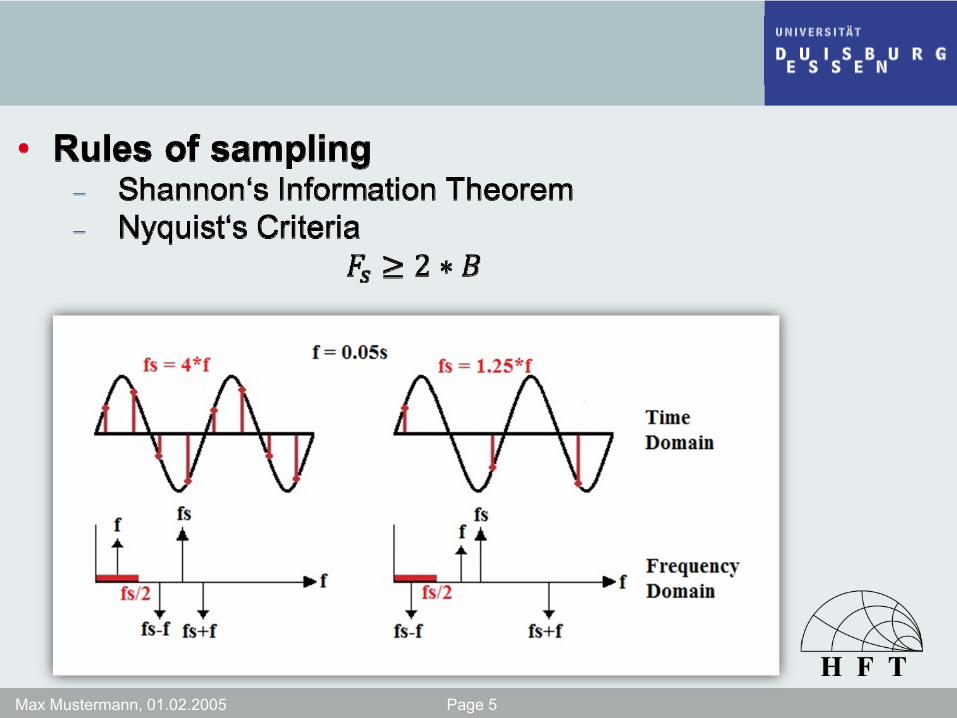
Sampling
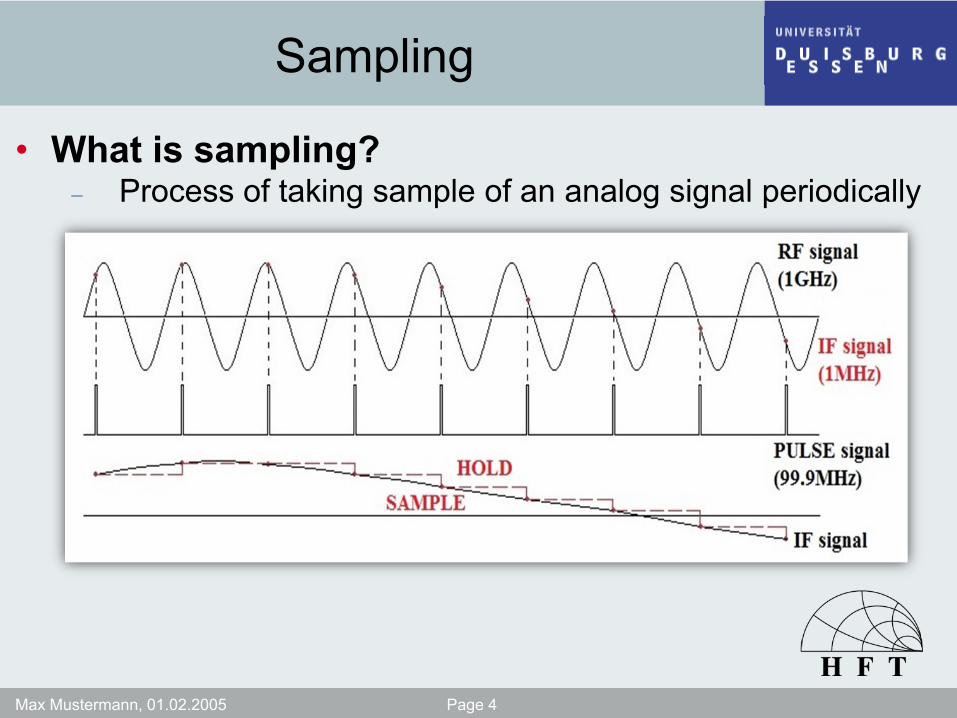
• What is sampling?− Process of taking sample of an analog signal periodically
Max Mustermann, 01.02.2005 Page 5
Max Mustermann, 01.02.2005 Page 6
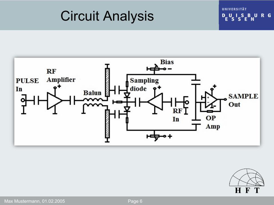
Circuit Analysis
Max Mustermann, 01.02.2005 Page 7
Max Mustermann, 01.02.2005 Page 8
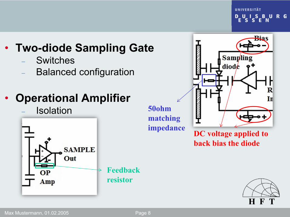
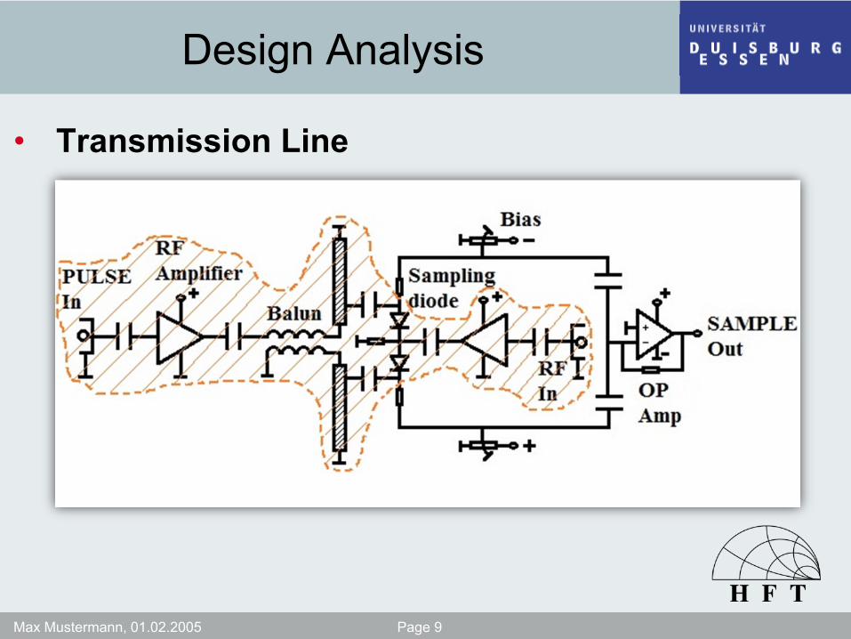
• Two-diode Sampling Gate− Switches− Balanced configuration
• Operational Amplifier− Isolation− Finite gain
DC voltage applied to back bias the diode
50ohm matching impedance
Feedback resistor
Max Mustermann, 01.02.2005 Page 9
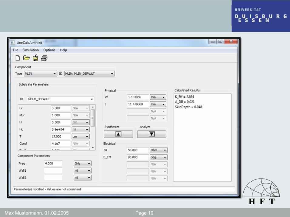
Design Analysis
• Transmission Line
Max Mustermann, 01.02.2005 Page 10
Max Mustermann, 01.02.2005 Page 11
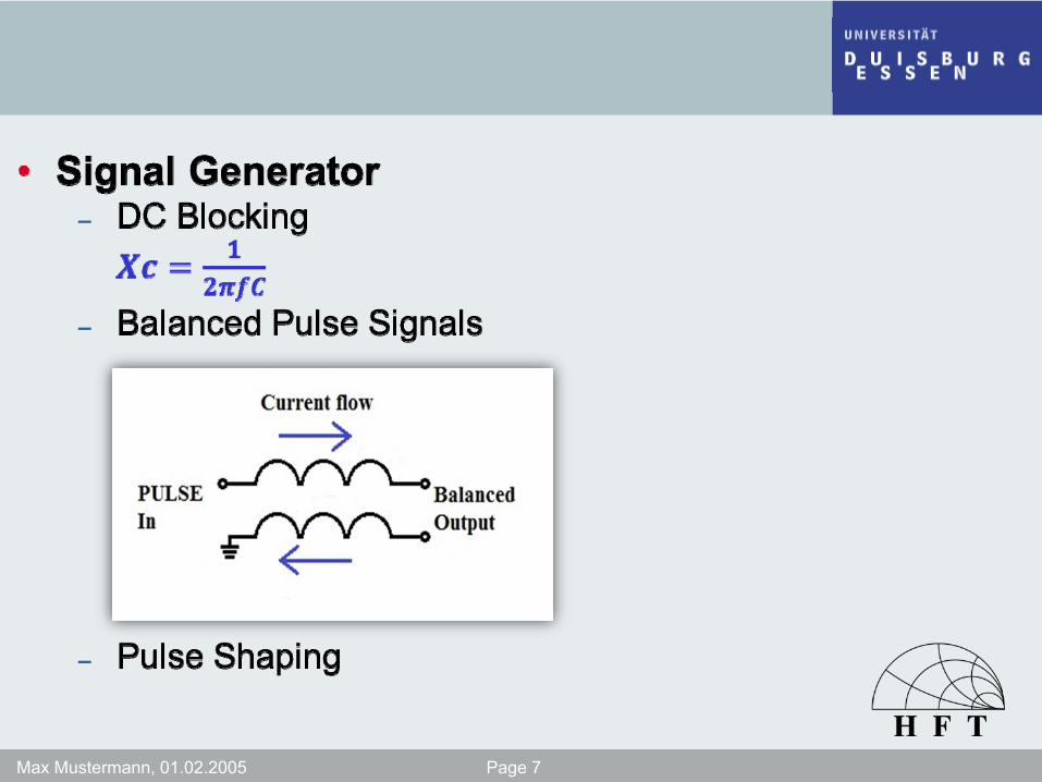
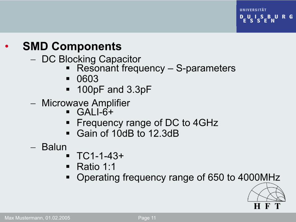
• SMD Components− DC Blocking Capacitor
Resonant frequency – S-parameters0603100pF and 3.3pF
− Microwave AmplifierGALI-6+Frequency range of DC to 4GHzGain of 10dB to 12.3dB
− BalunTC1-1-43+Ratio 1:1Operating frequency range of 650 to 4000MHz
Max Mustermann, 01.02.2005 Page 12
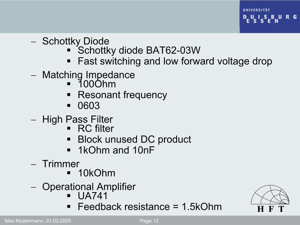
− Schottky DiodeSchottky diode BAT62-03WFast switching and low forward voltage drop
− Matching Impedance100OhmResonant frequency0603
− High Pass FilterRC filterBlock unused DC product1kOhm and 10nF
− Trimmer10kOhm
− Operational AmplifierUA741Feedback resistance = 1.5kOhm
Max Mustermann, 01.02.2005 Page 13
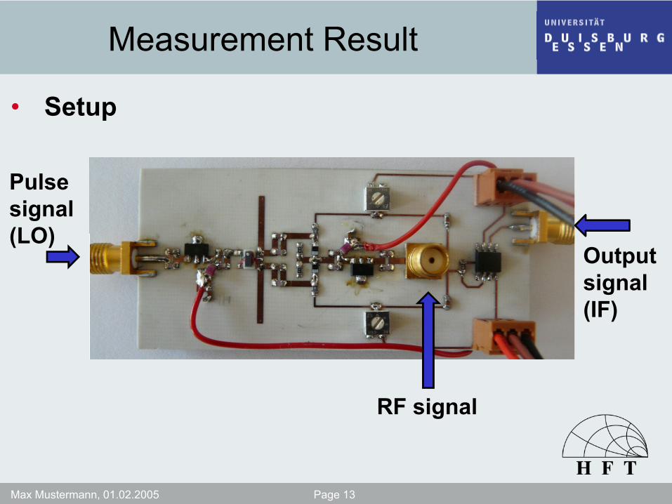
Measurement Result
• Setup
Pulse signal(LO)
RF signal
Output signal(IF)
Max Mustermann, 01.02.2005 Page 14
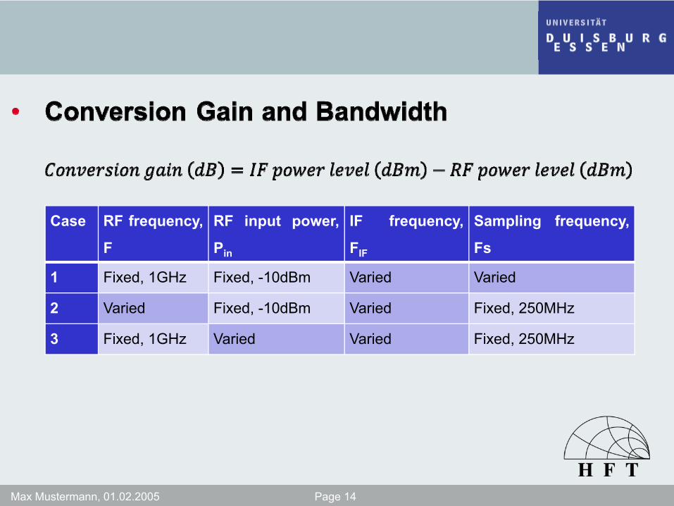
Case RF frequency
F
, RF input power
Pin
, IF frequency
FIF
, Sampling frequency,
Fs
1 Fixed, 1GHz Fixed, -10dBm Varied Varied
2 Varied Fixed, -10dBm Varied Fixed, 250MHz
3 Fixed, 1GHz Varied Varied Fixed, 250MHz

Max Mustermann, 01.02.2005 Page 15
-6
-5
-4
-3
-2
-1
0
4 6 8 10 20 40 60 80 100
120
140
160
180
200
220
240
260
280
300
320
340
360
380
400
420
440
460
480
500
Volta
ge G
ain,
dB
Frequency of IF Signal, kHz
F = 1GHz
F = 1.5GHz
F = 2GHz
F = 2.5GHz
Bandwidth = 400kHz
Max Mustermann, 01.02.2005 Page 16
-25
-20
-15
-10
-5
0
5
10 20 40 60 80 100
120
140
160
180
200
220
240
260
280
300
320
340
360
380
400
420
440
460
480
500
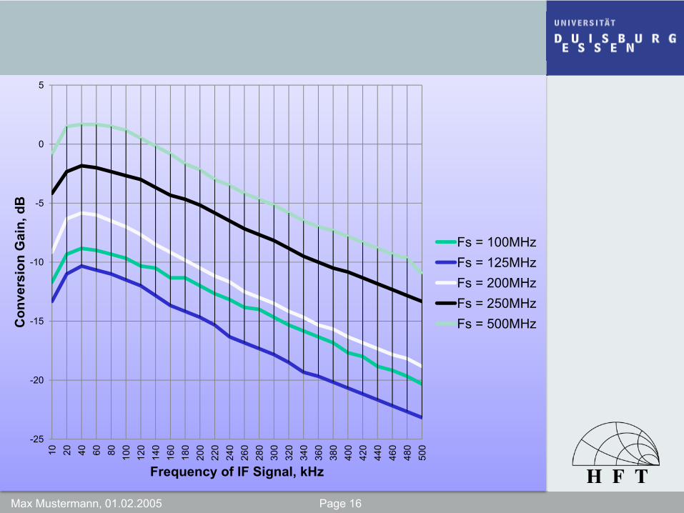
Con
vers
ion
Gai
n, d
B
Frequency of IF Signal, kHz
Fs = 100MHzFs = 125MHzFs = 200MHzFs = 250MHzFs = 500MHz
Max Mustermann, 01.02.2005 Page 17
-35
-30
-25
-20
-15
-10
-5
0
10 20 40 60 80 100
120
140
160
180
200
220
240
260
280
300
320
340
360
380
400
420
440
460
480
500
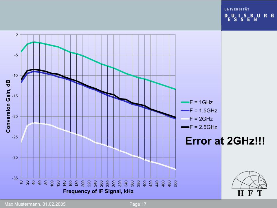
Con
vers
ion
Gai
n, d
B
Frequency of IF Signal, kHz
F = 1GHzF = 1.5GHzF = 2GHzF = 2.5GHz
Error at 2GHz!!!

Max Mustermann, 01.02.2005 Page 18
-30
-25
-20
-15
-10
-5
0
5
10 20 40 60 80 100
120
140
160
180
200
220
240
260
280
300
320
340
360
380
400
420
440
460
480
500
Con
vers
ion
Gai
n, d
B
Frequency of IF Signal, kHz
Pin = 0dBmPin = -5dBmPin = -10dBmPin = -15dBmPin = -20dBmPin = -25dBm
-10dBm is thesaturated inputpower to have linear characteristic
Max Mustermann, 01.02.2005 Page 19
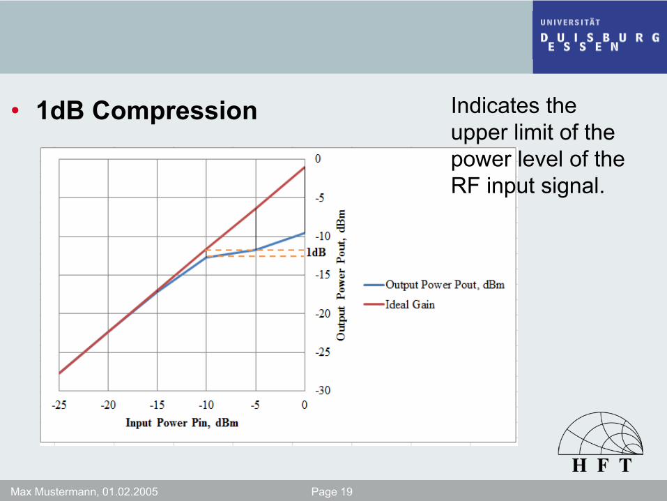
• 1dB Compression Indicates the upper limit of the power level of the RF input signal.
Max Mustermann, 01.02.2005 Page 20
• Isolation− RF-LO isolation = 30dB
decreased with increasing sampling frequency− IF-LO isolation = 25dB
System imbalance
Amount of power leakage that leaks from one port to another
Max Mustermann, 01.02.2005 Page 21
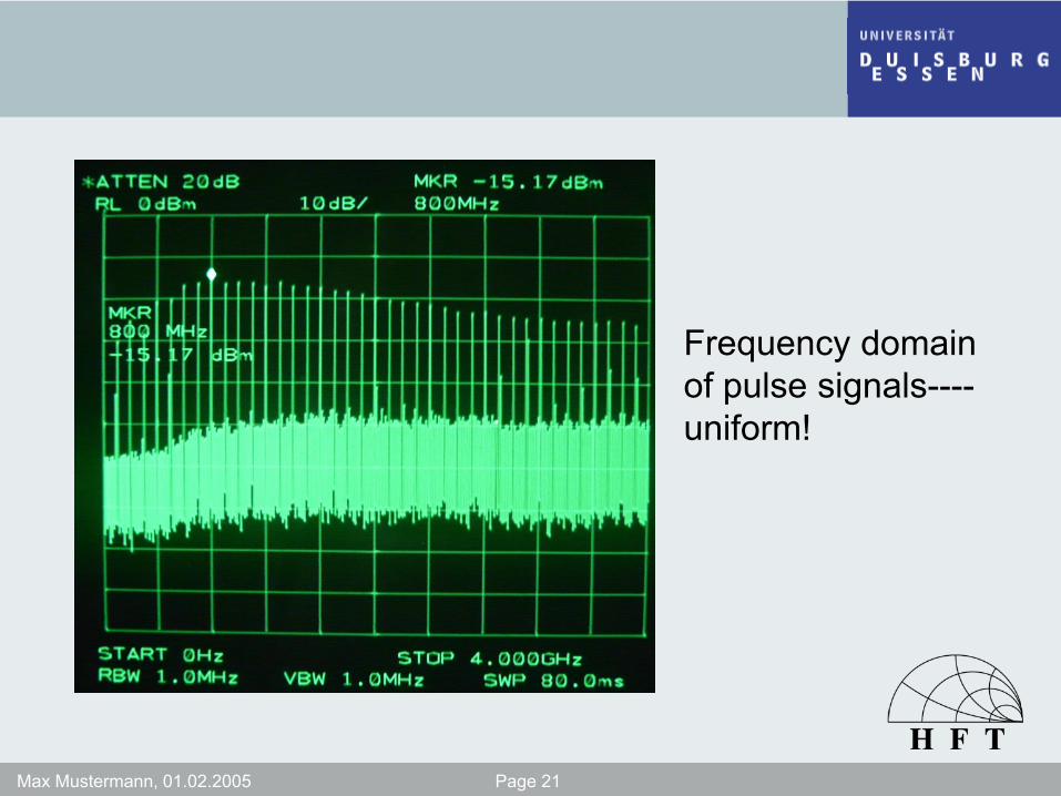
Frequency domainof pulse signals----uniform!
Max Mustermann, 01.02.2005 Page 22
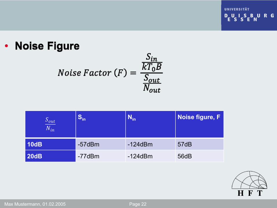
Sin Nin Noise figure, F
10dB -57dBm -124dBm 57dB
20dB -77dBm -124dBm 56dB

Max Mustermann, 01.02.2005 Page 23
• New Circuit
LEE-39+
TL071
Max Mustermann, 01.02.2005 Page 24
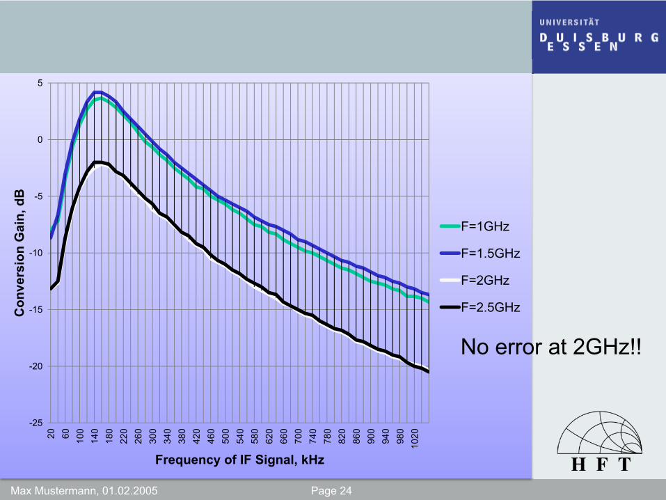
-25
-20
-15
-10
-5
0
5
20 60 100
140
180
220
260
300
340
380
420
460
500
540
580
620
660
700
740
780
820
860
900
940
980
1020
Con
vers
ion
Gai
n, d
B
Frequency of IF Signal, kHz
F=1GHz
F=1.5GHz
F=2GHz
F=2.5GHz
No error at 2GHz!!
Max Mustermann, 01.02.2005 Page 25
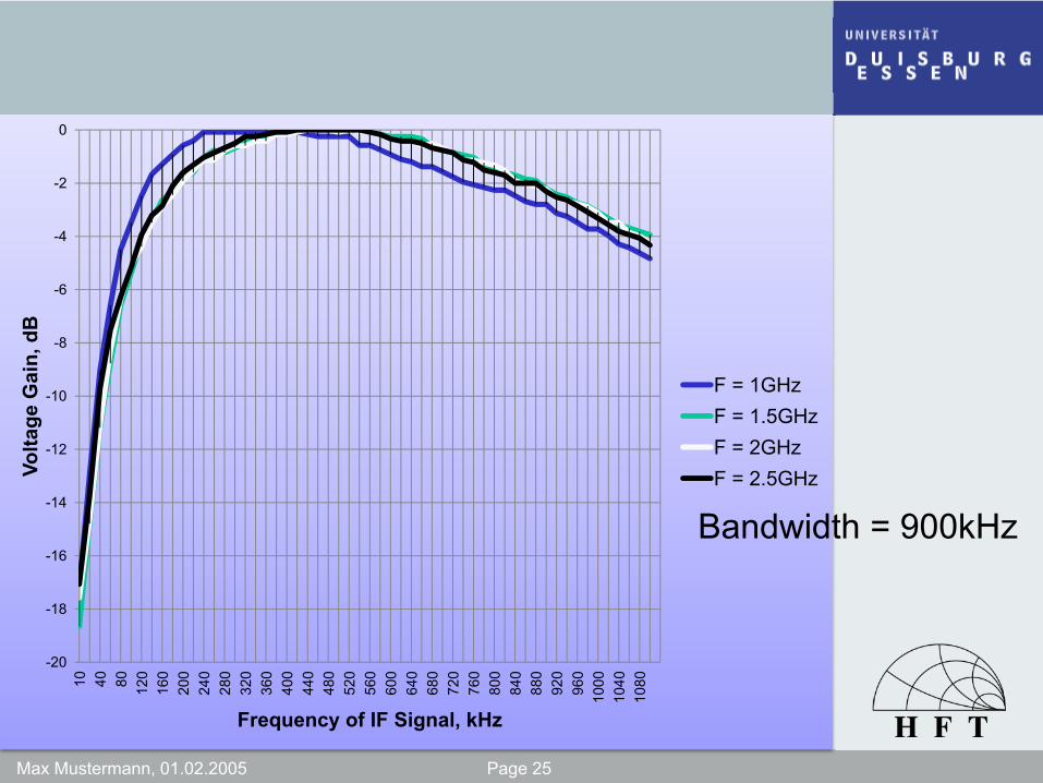
-20
-18
-16
-14
-12
-10
-8
-6
-4
-2
0
10 40 80 120
160
200
240
280
320
360
400
440
480
520
560
600
640
680
720
760
800
840
880
920
960
1000
1040
1080
Volta
ge G
ain,
dB
Frequency of IF Signal, kHz
F = 1GHzF = 1.5GHzF = 2GHzF = 2.5GHz
Bandwidth = 900kHz

Max Mustermann, 01.02.2005 Page 26


![RF Circuit Design - [Ch3-1] Microwave Network](https://static.fdocuments.net/doc/165x107/55d03525bb61ebc6768b45ac/rf-circuit-design-ch3-1-microwave-network.jpg)


