SAMPLE WELLHEAD PROTECTION PLAN€¦ · SAMPLE WELLHEAD PROTECTION PLAN For Town of Water...
71
SAMPLE WELLHEAD PROTECTION PLAN For Town of Water Customers, VA Adopted: 08/17/04 Mission Statement: to protect ground water which serves, or may serve in the future, as a source of public water supply. To protect it from the threat of contamination as a result of accidents or unwise practices from nearby residential, industrial, commercial, agricultural, waste management, or transportation activities. To cooperate with the Department of Health in carrying out the Safe Drinking Water Act purposes and provisions. August 16, 2004
-
Upload
truongduong -
Category
Documents
-
view
218 -
download
0
Transcript of SAMPLE WELLHEAD PROTECTION PLAN€¦ · SAMPLE WELLHEAD PROTECTION PLAN For Town of Water...

SAMPLE
WELLHEAD PROTECTION PLAN
For
Town of Water Customers, VA
Adopted: 08/17/04
Mission Statement: to protect ground water which serves, or may serve in the future, as a source
of public water supply. To protect it from the threat of contamination as a result of accidents or
unwise practices from nearby residential, industrial, commercial, agricultural, waste
management, or transportation activities. To cooperate with the Department of Health in
carrying out the Safe Drinking Water Act purposes and provisions.
August 16, 2004
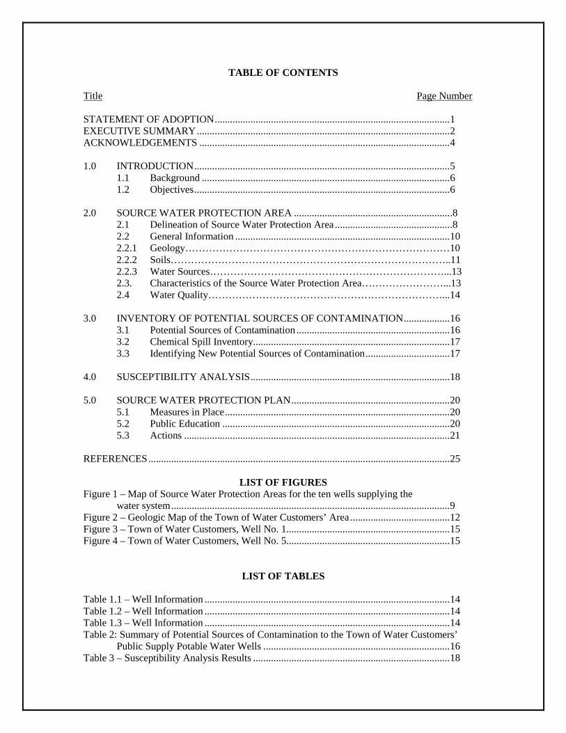
TABLE OF CONTENTS
Title Page Number STATEMENT OF ADOPTION ............................................................................................ 1 EXECUTIVE SUMMARY ................................................................................................... 2 ACKNOWLEDGEMENTS .................................................................................................. 4 1.0 INTRODUCTION .................................................................................................... 5
1.1 Background ................................................................................................. 6 1.2 Objectives .................................................................................................... 6
2.0 SOURCE WATER PROTECTION AREA ............................................................. .8
2.1 Delineation of Source Water Protection Area ............................................. .8 2.2 General Information .................................................................................... 10 2.2.1 Geology……………………………………………………………………10 2.2.2 Soils………………………………………………………………………..11 2.2.3 Water Sources……………………………………………………………...13 2.3. Characteristics of the Source Water Protection Area……………………...13 2.4 Water Quality……………………………………………………………...14
3.0 INVENTORY OF POTENTIAL SOURCES OF CONTAMINATION .................. 16
3.1 Potential Sources of Contamination ............................................................ 16 3.2 Chemical Spill Inventory............................................................................. 17 3.3 Identifying New Potential Sources of Contamination ................................. 17
4.0 SUSCEPTIBILITY ANALYSIS .............................................................................. 18
5.0 SOURCE WATER PROTECTION PLAN .............................................................. 20
5.1 Measures in Place ........................................................................................ 20 5.2 Public Education ......................................................................................... 20 5.3 Actions ........................................................................................................ 21
REFERENCES ...................................................................................................................... 25
LIST OF FIGURES Figure 1 – Map of Source Water Protection Areas for the ten wells supplying the water system ............................................................................................................. 9 Figure 2 – Geologic Map of the Town of Water Customers’ Area ....................................... 12 Figure 3 – Town of Water Customers, Well No. 1................................................................ 15 Figure 4 – Town of Water Customers, Well No. 5................................................................ 15
LIST OF TABLES
Table 1.1 – Well Information ................................................................................................ 14 Table 1.2 – Well Information ................................................................................................ 14 Table 1.3 – Well Information ................................................................................................ 14 Table 2: Summary of Potential Sources of Contamination to the Town of Water Customers’
Public Supply Potable Water Wells ......................................................................... 16 Table 3 – Susceptibility Analysis Results ............................................................................. 18

LIST OF APPENDICES
Appendix A Available Well Logs Appendix B Potential Sources of Contamination for the Town of Water Customers’
Wellhead Protection Areas Appendix C Various Potential Sources of Contamination Appendix D Sample Emergency Response Plan

Page 1
STATEMENT OF ADOPTION
The Town of Water Customers adopted the Town Source Water Assessment and
Protection Plan and has filed a copy of the plan with the Virginia Department of Health.
Copies of the plan can be obtained from:
Town of Water Customers 123 Main Street
Town of Water Customers, VA
This service and assistance of the members of the Source Water Protection Planning
Committee in preparation of the plan is acknowledged and greatly appreciated.
Water Operator Town Council Member Home Owner Business Owner
Concerned Citizen
By our signatures, we acknowledge the above statements to be true, and that we are
authorized by the Town of Water Customers to make such representation.
Name, Title Date Name, Secretary of Board or other Witness Date

Page 2
EXECUTIVE SUMMARY
Preventing the contamination of, and maintaining good quality drinking water supplies is
the primary goal of source water protection efforts under the Safe Drinking Water Act. The 1986
Amendments to the Safe Drinking Water Act established the Wellhead Protection Program.
Wellhead protection is a process of
identifying the area’s public water supply wells; assessing the potential risks to ground water in areas around these wells; and implementing measures to manage these risks and prevent ground water problems.
For the Town of Water Customers, the first two steps of this process were completed under
the Source Water Assessment Program of the Virginia Department of Health and are described in
the Source Water Assessment Report. The third step in the process – development and
implementation of a protection plan – is the focus of this report.
The Town of Water Customers water system is supplied by ten different wells.
Groundwater mainly flows through fractures and joints in bedrock to the town’s wells. Flow
velocities and gradients can be high and storage is limited in fractured aquifers (Nelms et. al,
2003). Key concerns as potential sources of contamination in the recharge zone (the Wellhead
Protection Area) include: on-site waste-water systems, residential fertilizer use and chemical
releases from underground and aboveground storage tanks.
The Local Advisory Committee (LAC) for this source water protection plan developed the
following recommended actions for helping to ensure the availability and quality of the water
supply for the Town of Water Customers for the future.
Develop a brochure describing Source Water Protection specifically for the town and promote the general education of the community on Source Water Protection.
Mail the Town of Water Customers SWP brochure to each residence in the SWPA
and to each water customer coincident with the distribution of the Consumer Confidence Report.

Page 3
Install signs along the roadway in high visibility locations near to the designated boundary of the wellhead protection area that state “Entering a Source Water Protection Area.”
Assess the concerns of the local gas station as a potential source of contamination.
Annually review with pertinent emergency response personnel (town and county)
the designated WHPA zone and appropriate response procedures.
Develop with the County the option of designating a Source Water Protection Overlay District for public water systems in the county.
Begin a routine maintenance and inspection schedule of septic systems within the
source water protection area.
Annually review and update the SWPP.
Page 4
ACKNOWLEDGEMENTS
Ground water protection needs to be a community effort; it is in everyone’s interest to
protect ground water and each can play an important role. It is in everyone’s interest to protect
ground water, and each can play an important role. The Source Water Assessment requirements
are delineation of the protection area, an inventory of the potential contaminant sources, and a
susceptibility analysis to determine the risk of contamination to the water source. The Town of
Water Customers has developed and provided this information to the public in the following
manner:
A Local Advisory Committee (LAC) was formed to develop and implement this Source
Water Protection Plan for the Town of Water Customers. A series of public meetings and work
sessions were held to gather input to develop this plan. The members included:
Water Operator
Home Owner
Business Owner
Town Council Member
Town Mayor
Concerned Citizen
The contribution and dedication of these LAC members is acknowledged by the Virginia
Department of Health and Olver Incorporated.
The Wellhead Protection Plan Efforts was funded by the Virginia Department of Health
and the Town of Water Customers.
Page 5
SECTION 1.0
INTRODUCTION
Protection of ground water which supports public water supplies is of vital importance to
Town of Water Customers. These public water supplies represent a substantial investment that
would be expensive to replace if their source of water were to become polluted. Once
contaminated, a groundwater reservoir may be permanently degraded or require costly augmented
remediation. Reducing or preventing chemical and microbiological contamination of source waters
could ideally allow public water systems to avoid costly treatments and minimize monitoring
requirements. When drinking water is contaminated, costs for drinking water contamination
include the following:
Providing emergency replacement water; Treatment and/or remediation expenses; Finding and developing new supplies; Paying for consulting services and staff time; Litigating against responsible parties; Conducting public information campaigns when incidents occur; Failure to meet the regulations of the Safe Drinking Water Act, such as the
Disinfection Byproduct and monitoring requirements; Loss of property value or tax revenue; Health related costs from exposure to contaminated water; Lost production of individuals and businesses, loss of economic development
opportunities; and Lack of community acceptance of treated drinking water. Providing emergency replacement water.
There are many normal day-to-day activities that could have the unintended consequence
of compromising the community’s drinking water supply. Underground storage tanks,
commercial, industrial, and agricultural activities, septic systems providing on-site wastewater
treatment, and hazardous materials passing along transportation corridors all have the potential of
being sources of contamination when they are in the recharge areas of the public water supply.
Groundwater is vulnerable to contamination by several pathways: infiltration from the
surface, leachate from onsite wastewater (septic) systems, injection of contaminants through

Page 6
improperly constructed or defective well, direct contamination of groundwater through sinkholes or
other geologic features, or by naturally occurring substances in the soil or rock. The properties of
the aquifer and overlying soils affect contaminant movement. Preventing contamination is the key
to keeping groundwater supplies safe.
1.1 Background
This Wellhead Protection Plan builds on previous work completed under the Source Water
Assessment Program of the Virginia Department of Health described in the source water
assessment report (Date of Report). The wellhead protection area (WHPA) and potential sources
of contamination defined in that study serve as the basis for this report which focuses on
developing and implementing a plan to provide high quality water to the Town for the present and
future.
The land within the wellhead protection area is predominately agricultural (pasture and
crops). Within the city limits (132 acres) the land use is predominately residential. The Town of
Water Customers has a population of approximately 1720 people. A business route passes through
the center of town. Sewage is disposed of using a sewer system which is treated at the treatment
plant located on the edge of the corporate limits northeast of town. The Town of Water Customers
has a number of small business including small scale retail and professional services.
1.2 Objectives
The objectives of the Town of Water Customers’ Wellhead Protection Plan are:
To promote public health, economic development and community infrastructure by maintaining an adequate drinking water supply for all residents of the community and region, both now and into the future.
To preserve and protect the quality of groundwater resources to assure continued
safe and useable water supply.
Specific Objectives of the Wellhead Protection Plan are: To protect ground water which serves, or may serve in the future, as a source of
public water supply;

Page 7
To protect ground water from the threat of contamination as a result of accidents or unwise practices from nearby residential, industrial, commercial, agricultural, waste management, or transportation activities; and
To cooperate with the Virginia Department of Health in carrying out the Safe
Drinking Water Act purposes and provisions.

Page 8
SECTION 2.0
SOURCE WATER PROTECTION AREA
2.1 Delineation of Source Water Protection Area
The Source Water Protection Area (also referred to as the Wellhead Protection Area) is the
area that will be managed by the Town in order to protect groundwater resources. The Wellhead
Protection Area (WHPA) is defined as the surface or subsurface area surrounding a water well
through which contaminants are reasonably likely to move toward and reach the water well. The
Source Water Protection Area was delineated by VDH as part of the source water assessment
program based on a fixed radius around each of the wells supplying Water Customers’ water. The
VDH assessment considered two different zones:
Zone 1 is a 1000 foot radius around the well and is a priority zone for
managing potential sources of contamination; and
Zone 2 is a one-mile (5,280 feet) radius which represents an estimate of the
total recharge zone for the well.
A map of the Source Water Protection Areas for Water Customers’ Wells may be found in
Figure 1.
The fixed radius approach to delineating the recharge zone was used as a reasonable first
approximation. More specific delineation of the recharge zone can be developed through a more
extensive evaluation of factors such as the hydrogeology in the vicinity of the well, daily
withdrawal rate of the well, watershed boundaries, topography, bedrock and surficial geology,
permeability and hydraulic conductivity of the bedrock structural geology, flow boundaries such as
ridges, rivers, canals and lakes, fracture traces and lineaments, and dissolution features such as
sinkholes. These evaluations may include groundwater basin boundary determination, Tiered Zone
boundary delineations, and/or groundwater discharge modeling.

Legend1000 ft Radius = Zone 1
1 Mile Radius = Zone 22,500
Feet.Figure 1:
Map of Source Water Protection Areas for the Ten Wells Supplying
the Water Customers Water System

Page 10
The groundwater basin boundary position is determined by the hydrologic, geologic and
climatic characteristics of the hydrogeologic setting and fluctuates seasonally. The boundary
marks the furthest locations from which groundwater will flow to the source as a hydraulically
connected stream. The common assumption that the position of the surface watershed boundary
approximates the position of the groundwater basin boundary is not universally true. Use of this
approximation may introduce significant error into the estimate of the position of the outermost
boundary of groundwater flow to a stream.
Examples of Tiered Zone protection area delineation methods include the following:
Example 1:
Zone 1 – protective zone around a well as determined by the pumping rate Zone 2 – zone of contribution or contributory area of the aquifer based on a 10-
year time of travel Zone 3 – the watershed drainage area that potentially contributes to the water
supply Example 2:
Zone 1 – 200 ft assumed essentially immediate travel to well Zone 2 – zone of groundwater that would travel to and be pumped up by the well
in a 5 year period (expected life time to replace a well) Zone 3 – 40-year time of travel zone (likely service life of the well)
Groundwater discharge models may be used to assess the potential impact of individual
contaminant sources and to identify watershed areas with the greatest potential impact on source
water quality. Modeling can be used in conjunction with source water assessments to enhance
source water quality protection efforts.
2.2 General Information
2.2.1. Geology
The Town of Water Customers is located in the Uplands of the Blue Ridge physiographic
province of Virginia. The rock types in the area are primarily metamorphic rocks (gneiss) of
Proterozoic Age. These metamorphic rocks were originally volcanic or sedimentary rocks. They

Page 11
were deposited when rifting was occurring similar to the Atlantic Ocean today. The rocks were
folded and faulted during the geologic period coincident with the formation of the present day
Appalachian Mountains. In general, ground waters produced in the region are from shallow
saprolite aquifers or deeper fractures in the bedrock. The gneiss bedrock has very low
permeability, so the groundwater can usually only flow through joints, fractures, and faults. In a
recent report on groundwater susceptibility in Virginia, this region was characterized as being of
high risk for contamination (Nelms et al, 2003). A geologic map of the Town of Water Customers
area is included in Figure 2.
2.2.2 Soils
According to the 1991 STATSGO Soil Survey, the primary soil in the area of Water
Customers’ wells is “Hayseville-Parker-Peaks.” This soil is described as a loam and is found on
2-7% slopes. It is included in the “B” hydrologic group of soils, which is characterized by
moderate infiltration rates (2-6 in/hr). The soil rarely floods and is considered a well-drained soil.
The pH of the soil ranges from 3.6 to 6.5 and the density is between 1.35 and 1.6 g/cm3. The depth
to the water table is at least 6 feet below land surface, and the depth to bedrock is at least 60 ft
below land surface. Soils types can be important because the rate the groundwater infiltrates
through the soil and type of plants that grown in the soil control the amount of precipitation that
reaches the groundwater.

Ymb
Jd
Jd
Jd
Jd
Zmd
Zmd
Zmd
Zmd
Zmd
Zmd
Yg
Figure 2: Geologic Map of Water Customer, VA
.0 1,300 2,600650Feet
LegendJd: Diabase
Zmd: MetadiabaseYmb: Biotitic metagranite
Map Source:U.S. Geological Survey Open-File Report 99-150
Main Street
Page 13
2.2.3. Water Resources
Water Customers is located in the Little Stream watershed. There are several creeks with
year round flow and a few ponds. None of the current surface water resources are suitable for
potable water supplies. The town uses emergency storage tanks to allow for enough water for fire
emergency situations.
Each of the surface water resources could act as a potential conduit to groundwater. The
water from the ponds and streams could infiltrate into the saprolite and directly into the
groundwater.
2.3 Characteristics of the Source Water Protection Area.
The Town of Water Customers (PWSID # 1234567) has 10 wells located within 2 miles of
each other. The following Tables 1.1 – 1.3 summarize information about each well.

Page 14
Table 1.1: Well Information Well ID# #1 #2 #3 #4 County County in VA County in VA County in VA County in VA Well Depth (ft) 307 423 400 267 Capacity (gpm) 24 33 42 28 Well and Pump Installer
Wells Inc Wells Inc Wells Inc Wells Inc
Status (in use/ not in use/in development)
In use In Use In Use In Use
Table 1.2: Well Information Well ID# #5 #6 #7 #8 County County in VA County in VA County in VA County in VAWell Depth (ft) 392 386 725 400 Capacity (gpm) 22 15 19 24 Well and Pump Installer
Wells Inc Wells Inc Wells Inc Wells Inc
Status (in use/ not in use/in development)
In use In Use In Use In Use
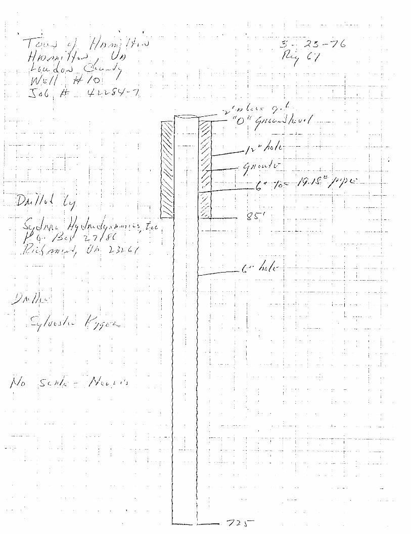
Table 1.3: Well Information Well ID# #9 #10 County County in VA County in VA Well Depth (ft) 835 Capacity (gpm) 45 Well and Pump Installer Wells Inc Wells Inc Status (in use/ not in use/in development) In use In Development
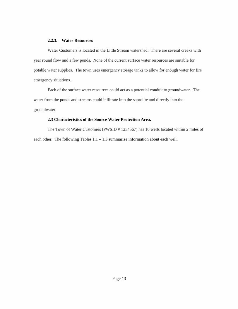
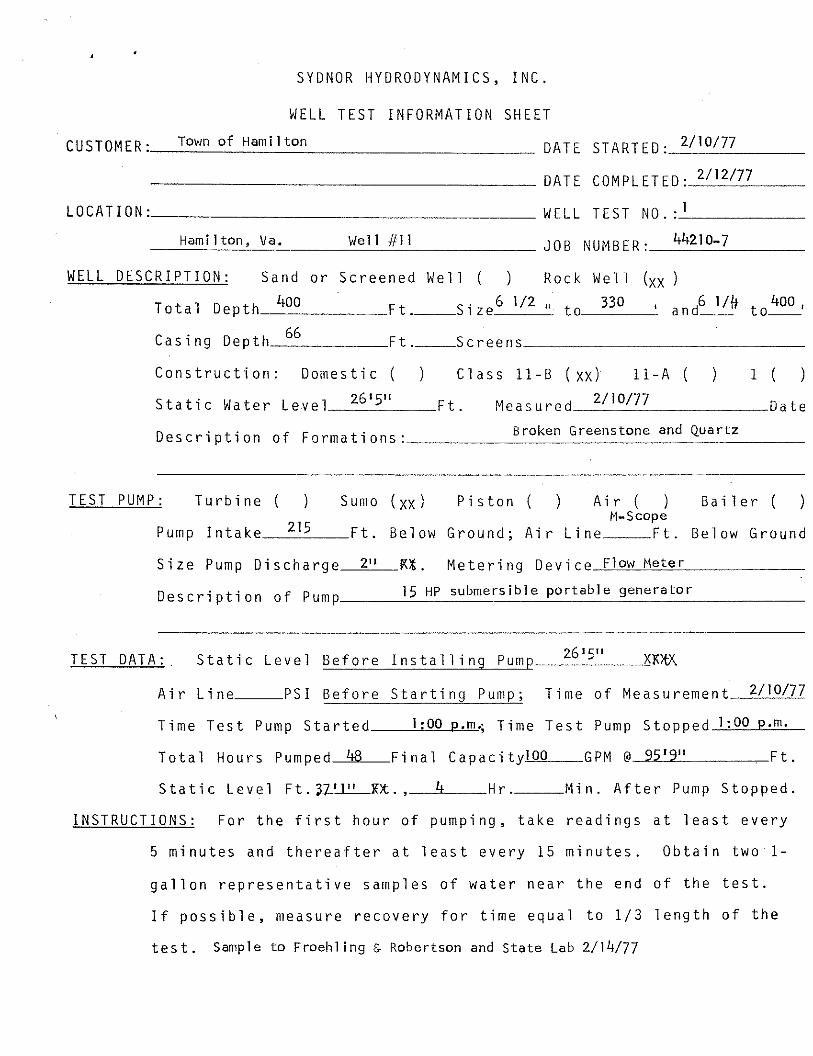
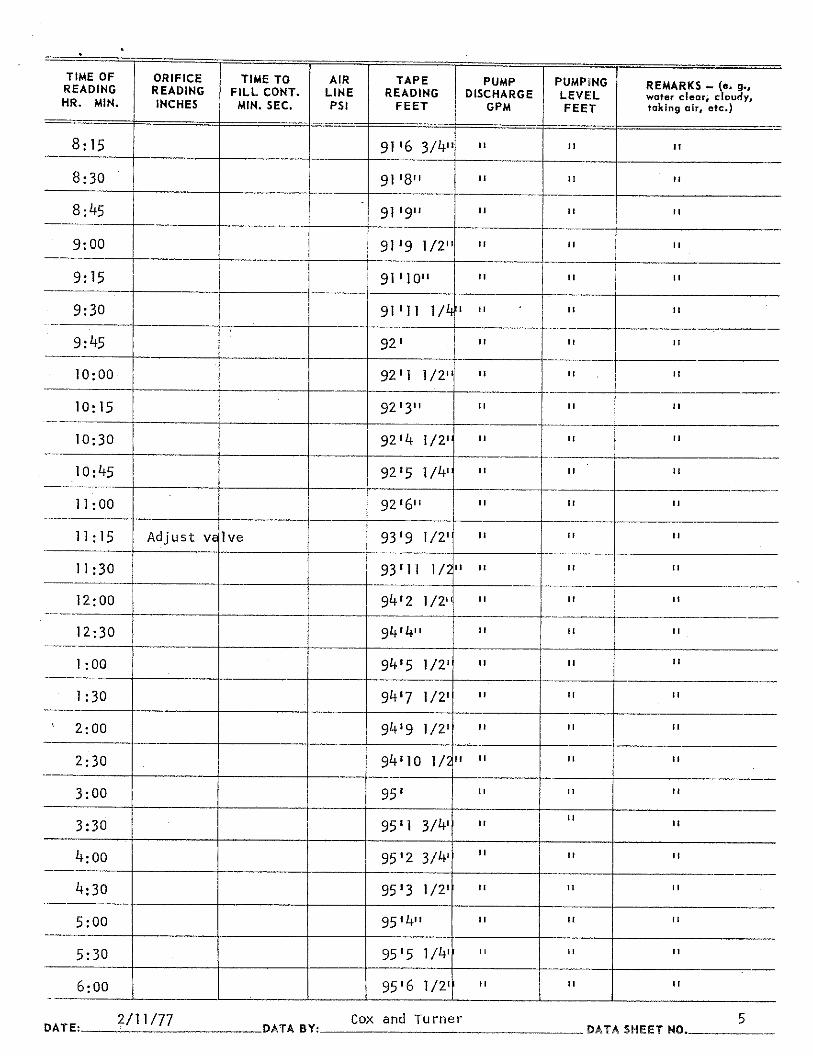
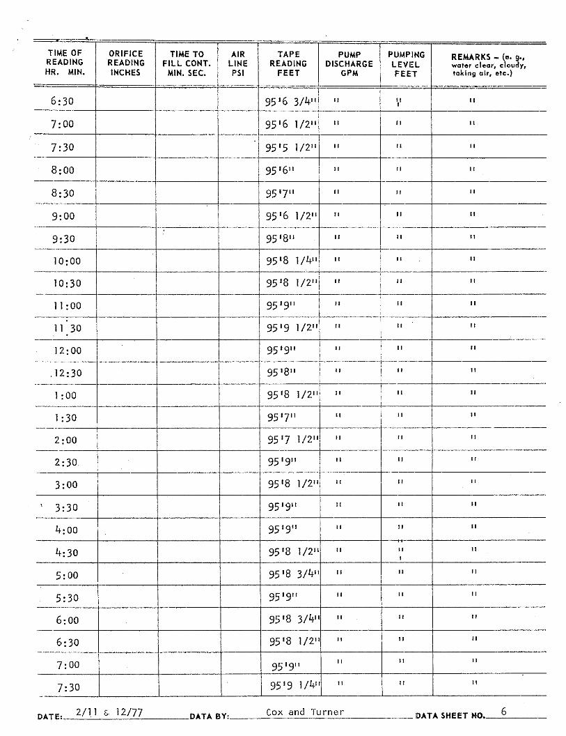
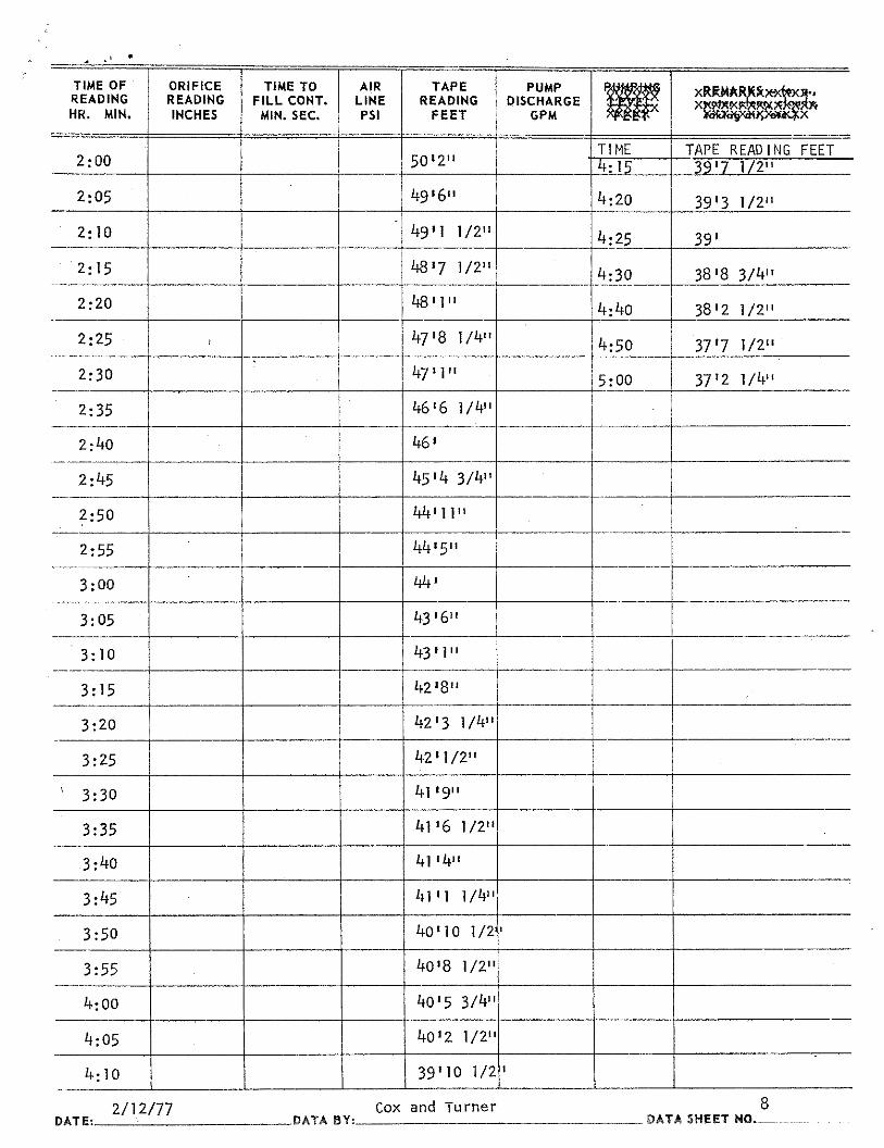
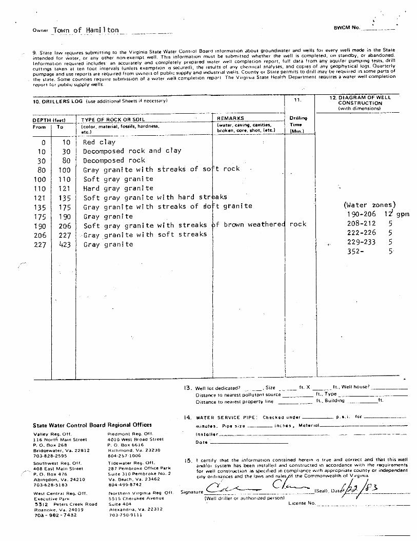
Figures 3-4 are pictures taken at the well site. The available well logs at the time of this
report may be found in Appendix A of this document.
2.4 Water Quality
Water Customers’ water is treated for iron and manganese using sand filters and carbon filtration.
The water is also chlorinated for disinfection. From 2000-2002, the Town of Water Customers’
was in compliance with all water quality, and reporting requirements. The Town is sampling its
water on a routine basis to meet all state and federal requirements administered by the VDH and
provides Annual Drinking Water Quality Reports to the public.
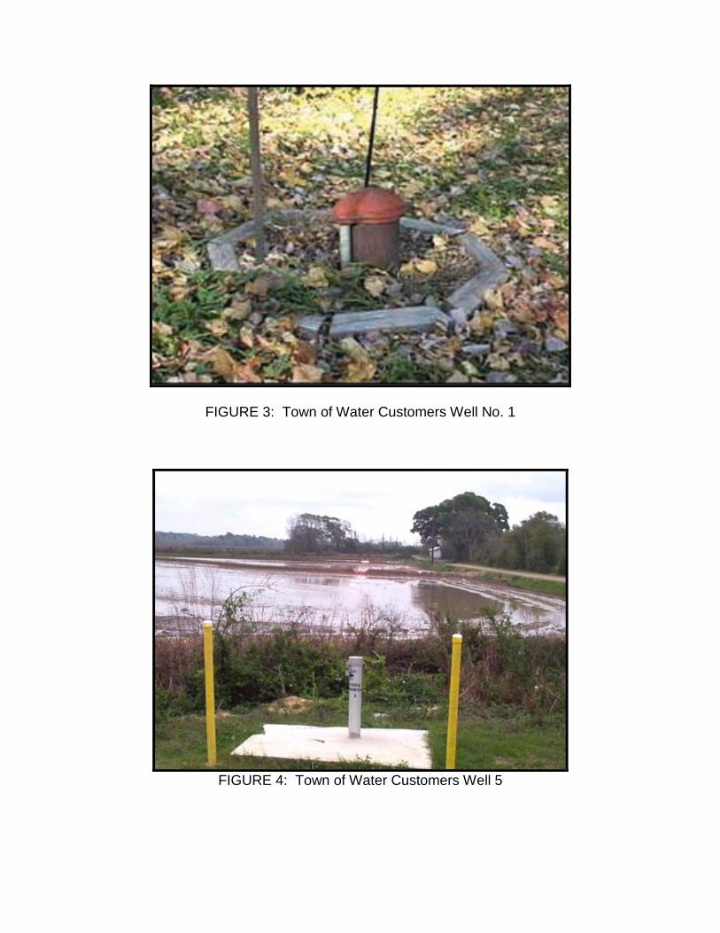
FIGURE 3: Town of Water Customers Well No. 1
FIGURE 4: Town of Water Customers Well 5
Page 16
SECTION 3.0
INVENTORY OF POTENTIAL SOURCES OF CONTAMINATION
3.1 Potential Sources of Contamination
The Source Water Assessment Report for Wells 1 -10, dated Month Date, Year was
developed by the Virginia Department of Health. Surveys of the 1000-foot and 1-mile protection
areas were completed for Wells 1-10 during Month Year.
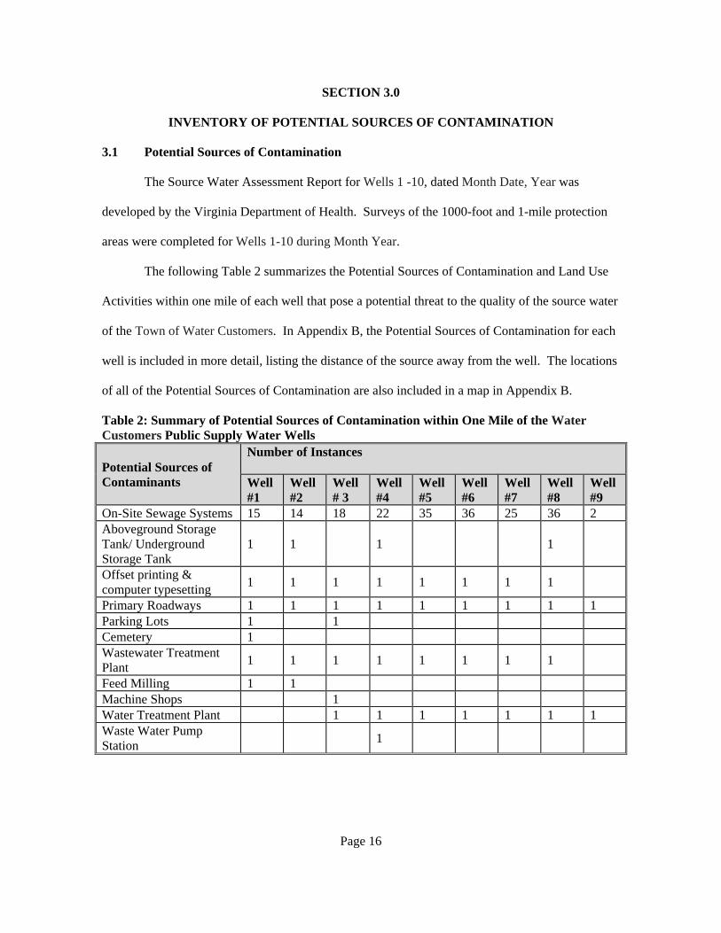
The following Table 2 summarizes the Potential Sources of Contamination and Land Use
Activities within one mile of each well that pose a potential threat to the quality of the source water
of the Town of Water Customers. In Appendix B, the Potential Sources of Contamination for each
well is included in more detail, listing the distance of the source away from the well. The locations
of all of the Potential Sources of Contamination are also included in a map in Appendix B.
Table 2: Summary of Potential Sources of Contamination within One Mile of the Water Customers Public Supply Water Wells
Potential Sources of Contaminants
Number of Instances Well #1
Well #2
Well # 3
Well #4
Well #5
Well #6
Well #7
Well #8
Well #9
On-Site Sewage Systems 15 14 18 22 35 36 25 36 2 Aboveground Storage Tank/ Underground Storage Tank
1 1 1 1
Offset printing & computer typesetting 1 1 1 1 1 1 1 1
Primary Roadways 1 1 1 1 1 1 1 1 1 Parking Lots 1 1 Cemetery 1 Wastewater Treatment Plant 1 1 1 1 1 1 1 1
Feed Milling 1 1 Machine Shops 1 Water Treatment Plant 1 1 1 1 1 1 1 Waste Water Pump Station 1

Page 17
3.2 Chemical Spill Inventory
In 1998 and 1999, Benzene was Well 10. While the amount did not exceed MCL for
Benzene the well was monitored according to state regulations during that time. The most
probable source of the benzene in the groundwater is a leaky underground storage tank for gasoline
and/or a gasoline spill.
3.3 Identifying New Potential Sources of Contamination
Identification of existing contamination sources may address immediate concerns about
protection of the local water supply. To ensure that the supply remains uncontaminated, continual
review of land use activities and identification of potential sources of contamination is necessary.
A summary listing of various sources of contamination that are commonly considered is included
in Appendix C.

Page 18
SECTION 4.0
SUSCEPTIBILITY ANALYSIS
The susceptibility analysis is a procedure for determining how the potential pollutant
sources identified in the inventory pose a risk to the quality of the source water. The results of the
Source Water Assessment Report are summarized in the following Table 3.
Table 3 : Susceptibility Analysis Results Source Name
Susceptibility to Contamination
Explanation
Well 1 High Groundwater source constructed in an area that tends to promote migration of contaminants with land use activities of concern in the Zone 1 Assessment area and potential sources of contamination in the Zone 1 or Zone 2 assessment areas.
Well 2 High Groundwater source constructed in an area that tends to promote migration of contaminants with land use activities of concern and potential conduits to groundwater in the Zone 1 Assessment area and potential sources of contamination in the Zone 1 or Zone 2 assessment areas.
Well 3 High Groundwater source constructed in an area that tends to promote migration of contaminants with land use activities of concern in the Zone 1 Assessment area and potential sources of contamination in the Zone 1 or Zone 2 assessment areas.
Well 4 High Groundwater source constructed in an area that tends to promote migration of contaminants with land use activities of concern and potential conduits to groundwater in the Zone 1 Assessment area and potential sources of contamination in the Zone 1 or Zone 2 assessment areas.
Well 5 High Groundwater source constructed in an area that tends to promote migration of contaminants with land use activities of concern in the Zone 1 Assessment area and potential sources of contamination in the Zone 1 or Zone 2 assessment areas.
Well 6 High Groundwater source constructed in an area that tends to promote migration of contaminants with land use activities of concern in the Zone 1 Assessment area and potential sources of contamination in the Zone 1 or Zone 2 assessment areas.
Well 7 High Groundwater source constructed in an area that tends to promote migration of contaminants with land use activities of concern and potential conduits to groundwater in the Zone 1 Assessment area and potential sources of contamination in the Zone 1 or Zone 2 assessment areas.
Well 8 High Groundwater source constructed in an area that tends to promote migration of contaminants with land use activities of concern in the Zone 1 Assessment area and potential sources of contamination in the Zone 1 or Zone 2 assessment areas.

Page 19
Source Name
Susceptibility to Contamination
Explanation
Well 9 High Groundwater source constructed in an area that tends to promote migration of contaminants with land use activities of concern and potential conduits to groundwater in the Zone 1 Assessment area and potential sources of contamination in the Zone 1 or Zone 2 assessment areas.
Well 10
High Groundwater source constructed in an area that tends to promotes migration of contaminants with land use activities of concern and potential conduits to groundwater in the Zone 1 assessment area and potential sources of contamination in the Zone 1 or Zone 2 assessment areas.
Page 20
SECTION 5.0
SOURCE WATER PROTECTION PLAN
The Source Water Protection Plan describes the actions necessary to minimize the risk to
the quality of the source water utilized by the Town of Water Customers. The goal of the plan is to
reduce or eliminate the potential threat to drinking water supplies within Wellhead Protection
Areas either through existing regulatory or statutory controls, or by using non-regulatory (and often
voluntary) measures centered around an involved public.
5.1 Measures in Place
The Town of Water Customers has identified general measures that are in place to assure
protection of the quality of the utilities’ source of water. These Water Quality Protection Measures
are a cross connection control plan and an effort to improve public sewer availability within the
town limits. In addition, best management practices were put in place to reduce the potential of
contamination reaching the source water as a result of land use. Some of the best management
practices within the wellhead protection area are a permanent vegetative cover on cropland, small
grain cover crop for nutrient management, and a sod waterway.
5.2 Public Education
In order for citizens to appreciate the benefits of source water/wellhead protection, they
must first understand what the problems are in providing safe drinking water, and how they can
become involved in the process. Examples of public education are brochures, pamphlets, field
days, mall displays, town meetings, and other mass-exposure opportunities to present wellhead
protection problems and protection efforts to the public in a straightforward, understandable
fashion. Public education is the greatest promoter of voluntary action and public support for a
community’s wellhead protection program.
A number of specific actions directed at public education are included in the
recommendations in the next section. These should be considered as a starting point. Other

Page 21
activities and opportunities should be sought that will increase public awareness that ground water
protection is a local issue and that each citizen plays a part.
5.3 Recommended Actions
After reviewing the physical characteristics land uses and potential sources of
contamination within the designated Source Water Protection Area the Town decided that the
following actions are recommended as initial step towards source water protection for the Town of
Water Customers.
1. Develop a brochure describing Source Water Protection specifically for the town.
Develop a brochure for the general public that addresses the following topics: general
overview of the importance of SWP; the local nature of groundwater recharge – what you
do matters; concerns with local geology; particular concerns with septic systems, wells,
sinkholes; and a list of general dos and don’ts.
2. Promote general education of the community on source water protection.
Make educational materials on SWP available to the public
Have pertinent brochures available for free distribution at the Town office, public library,
and other appropriate display/distribution locations. Such materials should include at least:
Water Customers’ SWP brochure
Brochures on septic system function and maintenance (available from EPA,
Va. DEQ, www.nsfc.wvu.edu etc.) that highlight the potential impact on
groundwater and the importance of regular pumping (3-5 years) to maintain
performance and life.
Add SWP information to the town web page (e.g. pdf or html of the brochure,
links to other resources).

Page 22
3. Mail the Water Customers’ SWP brochure to each residence in the SWPA and to each
water customer coincident with the distribution of the Consumer Confidence Report.
This mailing will occur every year beginning in 2005.
4. To increase local visibility and awareness of the SWPA, install signs along roads in high-
visibility locations near to the designated boundary of the wellhead protection area that
state “Entering Source Water Protection Area”. (Note that signs on road right-of-way
require approval of VDOT.)
5. Assess concerns of the local gas station as a potential source of contamination (PSC).
Because this site is physically up-slope of well 10, any contamination at this site would
move towards the well under sustained pumping.
Review status of the past environmental site assessment and remediation with DEQ.
Assess the potential risk of contamination from the site
Depending on the findings, take appropriate action which may include remediation or
implementing a monitoring program to sample existing or new wells down-gradient of the
site.
6. Annually review with pertinent emergency response personnel (town and county) the
designated WHPA zone and appropriate response procedures. Provide an emergency
information sheet that shows the WHPA, roads, and emergency contact information. An
annual meeting/training/review with emergency response personnel (added as a component
to regular training programs) to highlight the significance of the WHPA and review
appropriate response procedures for incidents in the WHPA. Such actions should include
the following in the event of a spill or potential source of contamination:

Page 23
Immediate notification of the waterworks operator
Use of best available cleanup procedures
Minimize potential for movement to groundwater
7. Develop with the County the option of designating a Source Water Protection Overlay
District for public water systems in the county that would:
a) specify minimum restriction for WHPAs (i.e. provide a generic SWP Overlay), and/or
b) allow the designation of a specific Overlay District proposed by the town
Concerns that could be addressed include: restriction of certain type of businesses
and activities, regular inspection and maintenance of septic systems, guidelines on
approval and abandonment of private wells.
A reference guide with model language can be found in: "Implementing Wellhead
Protection: Model Components for Local Governments in Virginia" by the Virginia
Groundwater Protection Steering Committee (1998).
8. Provide a schedule for inspection and maintenance of septic systems within wellhead
protection area.
Each of the septic systems within the wellhead protection zone will be required to
be inspected annually and maintained (i.e. pumped out) every 3 years. The town will begin
this process by enacting the appropriate ordinance at the Town Council Meeting. Then, the
town will launch a public education campaign notifying those owners of septic systems
about inspections and maintenance and importance to source water protection. Finally an
inspection and maintenance schedule will be implemented to ensure that the ordinance is
followed through to compliance.

Page 24
9. Annually review and update the SWPP
Identify and update list of PSCs
Review educational program
Assess progress on achieving the SWPP goals

Page 25
REFERENCES
VDH, 2003. Source Water Assessment Report – Town of Water Customers. (Month Year).
Prepared by the Virginia Department of Health. Nelms, D.L., Harlow, Jr., G.E., Plummer L.N., and Busenberg, E., 2003. Aquifer Susceptibility in
Virginia, 1998-2000. USGS Water Resources Investigation Report 03-4278. 67pp USDA. 1991. State Soil Geographic (STATSGO) Database for Virginia. U.S. Department of
Agriculture, Natural Resources Conservation Service. Virginia Groundwater Protection Steering Committee, (1998). "Implementing Wellhead
Protection: Model Components for Local Governments in Virginia"

APPENDIX A
Available Well Logs
Town of Water Customers, VA

swarner
swarner


APPENDIX B
Potential Sources of Contamination for Water Customer’s Wellhead
Protection Areas
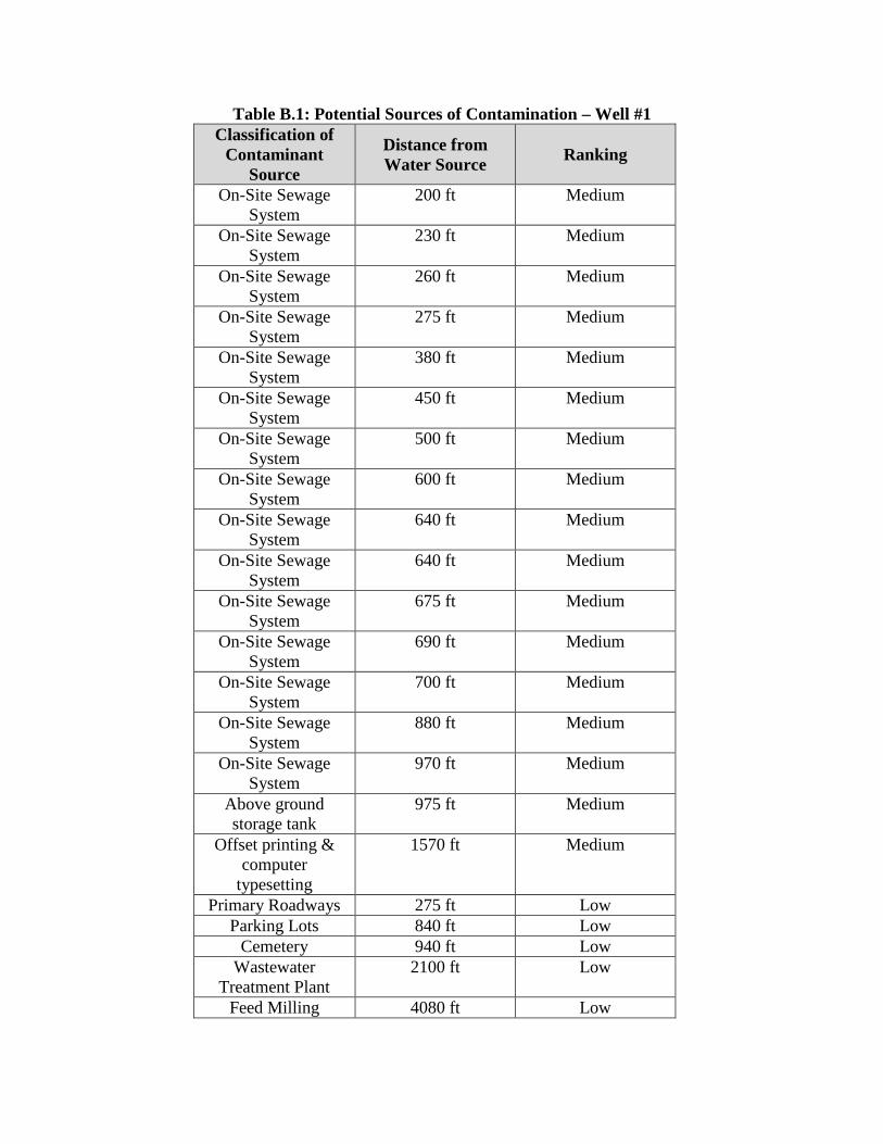
Table B.1: Potential Sources of Contamination – Well #1 Classification of
Contaminant Source
Distance from Water Source Ranking
On-Site Sewage System
200 ft Medium
On-Site Sewage System
230 ft Medium
On-Site Sewage System
260 ft Medium
On-Site Sewage System
275 ft Medium
On-Site Sewage System
380 ft Medium
On-Site Sewage System
450 ft Medium
On-Site Sewage System
500 ft Medium
On-Site Sewage System
600 ft Medium
On-Site Sewage System
640 ft Medium
On-Site Sewage System
640 ft Medium
On-Site Sewage System
675 ft Medium
On-Site Sewage System
690 ft Medium
On-Site Sewage System
700 ft Medium
On-Site Sewage System
880 ft Medium
On-Site Sewage System
970 ft Medium
Above ground storage tank
975 ft Medium
Offset printing & computer
typesetting
1570 ft Medium
Primary Roadways 275 ft Low Parking Lots 840 ft Low
Cemetery 940 ft Low Wastewater
Treatment Plant 2100 ft Low
Feed Milling 4080 ft Low

Table B.2 : Potential Sources of Contamination – Well #2 Classification of
Contaminant Source
Distance from Water Source Ranking
Above ground storage tank
80 ft Medium
On-site sewage system
580 ft Medium
On-site sewage system
630 ft Medium
On-site sewage system
630 ft Medium
On-site sewage system
680 ft Medium
On-site sewage system
685 ft Medium
On-site sewage system
705 ft Medium
On-site sewage system
820 ft Medium
On-site sewage system
840 ft Medium
On-site sewage system
880 ft Medium
On-site sewage system
910 ft Medium
On-site sewage system
925 ft Medium
On-site sewage system
925 ft Medium
On-site sewage system
925 ft Medium
On-site sewage system
965 ft Medium
Offset printing & computer
typesetting
2085 ft Medium
Wastewater treatment plant
1810 ft Low
Feed Milling 3060 ft Low

Table B.3 : Potential Sources of Contamination – Well #3
Classification of Contaminant
Source
Distance from Water Source Ranking
On-site sewage systems
160 ft Medium
On-site sewage systems
230 ft Medium
On-site sewage systems
365 ft Medium
On-site sewage systems
405 ft Medium
On-site sewage systems
460 ft Medium
On-site sewage systems
540 ft Medium
On-site sewage systems
545 ft Medium
On-site sewage systems
610 ft Medium
On-site sewage systems
660 ft Medium
On-site sewage systems
660 ft Medium
On-site sewage systems
730 ft Medium
On-site sewage systems
760 ft Medium
On-site sewage systems
770 ft Medium
On-site sewage systems
775 ft Medium
On-site sewage systems
870 ft Medium
Machine Shops 875 ft Medium On-site sewage
systems 905 ft Medium
On-site sewage systems
925 ft Medium
On-site sewage systems
975 ft Medium
Offset printing & computer
typesetting
4640 ft Medium
Parking Lots 830 ft Low

Classification of Contaminant
Source
Distance from Water Source Ranking
Water Treatment Plant
2475 ft Low
Wastewater Treatment Plant
5000 ft Low
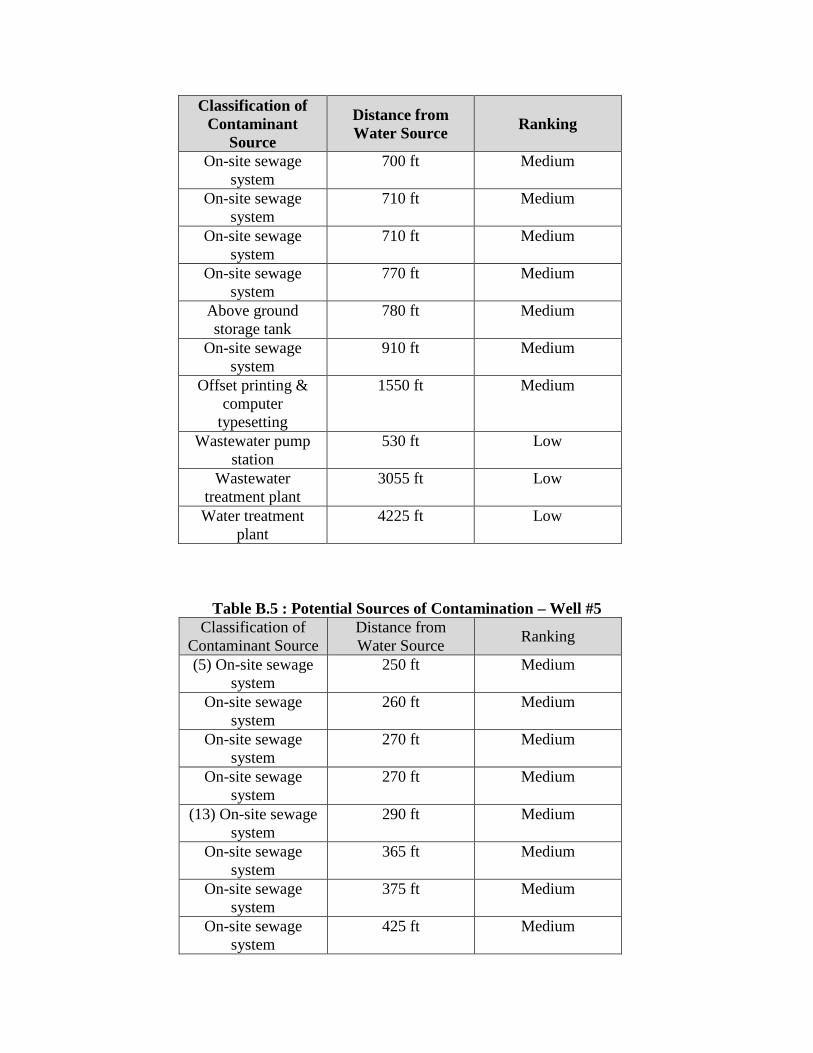
Table B.4 : Potential Sources of Contamination – Well #4
Classification of Contaminant
Source
Distance from Water Source Ranking
On-site sewage system
130 ft Medium
On-site sewage system
170 ft Medium
On-site sewage system
215 ft Medium
On-site sewage system
270 ft Medium
On-site sewage system
335 ft Medium
On-site sewage system
360 ft Medium
On-site sewage system
400 ft Medium
On-site sewage system
435 ft Medium
On-site sewage system
460 ft Medium
On-site sewage system
460 ft Medium
On-site sewage system
510 ft Medium
On-site sewage system
515 ft Medium
On-site sewage system
560 ft Medium
On-site sewage system
595 ft Medium
On-site sewage system
630 ft Medium
On-site sewage system
635 ft Medium
On-site sewage system
670 ft Medium
Classification of Contaminant
Source
Distance from Water Source Ranking
On-site sewage system
700 ft Medium
On-site sewage system
710 ft Medium
On-site sewage system
710 ft Medium
On-site sewage system
770 ft Medium
Above ground storage tank
780 ft Medium
On-site sewage system
910 ft Medium
Offset printing & computer
typesetting
1550 ft Medium
Wastewater pump station
530 ft Low
Wastewater treatment plant
3055 ft Low
Water treatment plant
4225 ft Low
Table B.5 : Potential Sources of Contamination – Well #5
Classification of Contaminant Source
Distance from Water Source Ranking
(5) On-site sewage system
250 ft Medium
On-site sewage system
260 ft Medium
On-site sewage system
270 ft Medium
On-site sewage system
270 ft Medium
(13) On-site sewage system
290 ft Medium
On-site sewage system
365 ft Medium
On-site sewage system
375 ft Medium
On-site sewage system
425 ft Medium

Classification of Contaminant Source
Distance from Water Source Ranking
On-site sewage system
525 ft Medium
On-site sewage system
540 ft Medium
On-site sewage system
575 ft Medium
On-site sewage system
630 ft Medium
On-site sewage system
690 ft Medium
On-site sewage system
710 ft Medium
On-site sewage system
740 ft Medium
On-site sewage system
790 ft Medium
On-site sewage system
790 ft Medium
On-site sewage system
810 ft Medium
On-site sewage system
845 ft Medium
Offset printing & computer
typesetting
4070 ft Medium
Water treatment plant
670 ft Low
Wastewater treatment plant
5060 ft Low
Table B.6 : Potential Sources of Contamination – Well #6 Classification of
Contaminant Source
Distance from Water Source Ranking
(12) On-site sewage system
120 ft Medium
On-site sewage system
290 ft Medium
(5) On-site sewage system
295 ft Medium
On-site sewage system
390 ft Medium
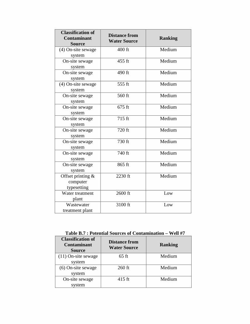
Classification of Contaminant
Source
Distance from Water Source Ranking
(4) On-site sewage system
400 ft Medium
On-site sewage system
455 ft Medium
On-site sewage system
490 ft Medium
(4) On-site sewage system
555 ft Medium
On-site sewage system
560 ft Medium
On-site sewage system
675 ft Medium
On-site sewage system
715 ft Medium
On-site sewage system
720 ft Medium
On-site sewage system
730 ft Medium
On-site sewage system
740 ft Medium
On-site sewage system
865 ft Medium
Offset printing & computer
typesetting
2230 ft Medium
Water treatment plant
2600 ft Low
Wastewater treatment plant
3100 ft Low
Table B.7 : Potential Sources of Contamination – Well #7
Classification of Contaminant
Source
Distance from Water Source Ranking
(11) On-site sewage system
65 ft Medium
(6) On-site sewage system
260 ft Medium
On-site sewage system
415 ft Medium

Classification of Contaminant
Source
Distance from Water Source Ranking
On-site sewage system
480 ft Medium
On-site sewage system
545 ft Medium
On-site sewage system
550 ft Medium
On-site sewage system
700 ft Medium
On-site sewage system
805 ft Medium
On-site sewage system
820 ft Medium
On-site sewage system
840 ft Medium
Offset printing & computer
typesetting
3275 ft Medium
Water treatment plant
2190 ft Low
Wastewater treatment plant
4690 ft Low
Table B.8 : Potential Sources of Contamination – Well #8
Classification of Contaminant
Source
Distance from Water Source Ranking
(12) On-site sewage system
160 ft Medium
On-site sewage system
260 ft Medium
(5) On-site sewage system
260 ft Medium
(4) On-site sewage system
380 ft Medium
On-site sewage system
380 ft Medium
On-site sewage system
480 ft Medium
On-site sewage system
500 ft Medium
(4) On-site sewage system
570 ft Medium

Classification of Contaminant
Source
Distance from Water Source Ranking
On-site sewage system
580 ft Medium
On-site sewage system
720 ft Medium
On-site sewage system
720 ft Medium
On-site sewage system
730 ft Medium
On-site sewage system
765 ft Medium
On-site sewage system
770 ft Medium
On-site sewage system
880 ft Medium
Offset printing & computer
typesetting
2200 ft Medium
Water treatment plant
2650 ft Low
Wastewater treatment plant
3060 ft Low
Table B.9: Potential Sources of Contamination – Well #9 Classification of Contaminant Source
Distance from Water Source
Ranking
On-site sewage system
220 ft Medium
(11) On-site sewage system
230 ft Medium
On-site sewage system
285 ft Medium
On-site sewage system
380 ft Medium
On-site sewage system
475 ft Medium
On-site sewage system
535 ft Medium
On-site sewage system
545 ft Medium
On-site sewage system
555 ft Medium

Classification of Contaminant Source
Distance from Water Source
Ranking
On-site sewage system
555 ft Medium
Fuel Storage System 565 ft Medium On-site sewage
system 665 ft Medium
On-site sewage system
670 ft Medium
(4) On-site sewage system
690 ft Medium
On-site sewage system
695 ft Medium
On-site sewage system
700 ft Medium
On-site sewage system
760 ft Medium
On-site sewage system
785 ft Medium
On-site sewage system
795 ft Medium
(4) On-site sewage system
830 ft Medium
On-site sewage system
965 ft Medium
On-site sewage system
995 ft Medium
Offset printing & computer
typesetting
2200 ft Medium
Water treatment plant
3300 ft Low
Wastewater treatment plant
3700 ft Low
Table B.10 : Potential Sources of Contamination – Well #10
Classification of Contaminant
Source
Distance from Water Source Ranking
On-site sewage system
430 ft Medium
On-site sewage system
955 ft Medium
Water treatment plant
1750 ft Low


2
47
Legend1 Mile Radius = WHPA
1,700Feet
.Figure B.1
Potential Sources Of Contamination
Aerial Photography (C) 2002 Commonwealth of Virginia
Potential Sources of ContaminationOther
Cemetery
Fuel Storage Systems
Machine Shops
On-site sewage system
Parking Lots
Primary Roadways
Wastewater Pump Station
Wastewater Treatment Facility
Above ground storage tank (> 660 gallons)

APPENDIX C
Various Potential Sources of Contamination

According to the Virginia Ground Water Protection Steering Committee, the following
land uses can pose threats to ground water. This is provided to demonstrate potential sources the
Town should be aware of and plan for. Many of the following sources of pollution are not
currently present in the Town of Water Customer’s source water protection areas, but citizens
should be aware of their potential impact and keep them in mind for future plans for the area.
Residential
Threats to ground water from residential uses are normally less acute on a case-by-case
basis than those from other, more intensive, land uses. The cumulative effect from many
residents in an area can prove to be a serious problem, however, especially if owners are unaware
of the numerous potential contaminants that can be found in the home and yard and the proper
methods for their use and disposal. Examples of potential residential sources include:
• On-site septic systems (e.g. nitrates, bacteria and viruses, household cleaners) • Sewer lines • Fuel storage • Lawn chemicals (e.g. pesticides, fertilizers) • Automotive and pool chemicals • Storm water • Abandoned wells • Road deicing operations (e.g. road salt) • Household activities chemicals (e.g. solvents, paints, household cleaners)
Industrial
Industrial operations commonly use toxic substance as part of manufacturing,
warehousing, and/or distribution. Materials such as chemicals, petroleum, cleaning supplies,
machinery, metals, electronic products, asphalt, and others pose a potential threat unless carefully
managed. Activities representing the greatest concern include the following.
• Mining, quarrying • Pipelines • Storage tanks (above and underground) • Operating and abandoned wells (e.g., gas, oil, water, monitoring and exploration) • Septage and sludge lagoons • Land application of sludge

Even small quantities of toxic and hazardous waste chemicals can contaminate water
resources. These chemicals should never be put directly into the ground and their containers
should not be discarded on the ground, or in the trash.
Underground storage of hazardous materials has historically been a significant source of
groundwater contamination. Even a small leak can contaminate a substantial amount of water.
Commercial
Many commercial operations use toxic and hazardous materials in their processes. The
storage, use and disposal of chemicals required by these operations can pose a potential threat to
ground water, since even small amounts of the hazardous materials can contaminate large
amounts of ground water. Specific examples of land uses of concern include:
• Auto repair shops, gas stations (e.g. oils, greases, solvents, antifreeze, gasoline) • Road maintenance depots, de-icing operations • Boat yards, railroad tracks and yards, airports • Construction areas • Dry cleaners, Laundromats • Medical institutions, research laboratories • Photography establishments, printers • Golf courses (chemical application)
Agricultural
Chemical usage associated with farming activities can present a contamination threat to
underlying ground water. Pesticides, fungicides, and fertilizers can leach through the soil to the
water below when applied improperly in the field. They also have the potential to leak from any
storage containers into the ground. Animal feedlots and livestock operations can create excessive
nitrate/nitrite and bacteriological problems if animal waste loads, whether dry or liquid, are high
and ground water is shallow or the soil is permeable. Specific concerns for farming include:
• Pesticides, fungicides • Fertilizers • Feedlots, confined animal feeding operations
Waste Management
Disposal of wastes must be handled carefully to prevent contamination of ground water.
Older landfills in particular can threaten ground water. In lined landfills, reliance is placed on the
liner not failing after a number of years. Landfills are known sources of contamination and
typically result in pollutants including nutrients, metals and hydrocarbons. The need to manage
“waste” stormwater is created by most development – residential, commercial and industrial –
since impervious surface prevent rain from soaking into the soil. Sites of greatest concern can
include:
• Landfills • Impervious surfaces • Basins, lagoons
Transportation
Facilities moving potentially contaminating liquids or materials through an area can
result in spills and accidents in locations near public water supplies. Preventing escape of such
materials is crucial as is rapid response. Specific sources of concern may include:
• Pipelines • Highways • Airports • Rail lines

APPENDIX D
Sample Emergency Response Plan

Page D-1
SAMPLE EMERGENCY CONTINGENCY PLAN
Contingency planning is the development and implementation of both long and short-term
drinking water supply replacement strategies for supplying safe drinking water to the customer in
the event of contamination or physical disruption. The Source Water Emergency Contingency Plan
included below describes steps to follow in the event that a natural or man-made disaster makes the
water source unusable. This plan is not designed to cover all occurrences, rather it is contains
essential information that would be needed if the source water supply were directly affected.
Emergency Response Personnel
The Town of Water Customers has designated an Emergency Response Leader and
Alternates that will be responsible for responding to emergency situations concerning the source
water. The following emergency response personnel should be contacted immediately in the event
of an emergency.
Emergency Response Personnel and Critical Water Users
Emergency Response Leader 1st Alternate
Name Water Operator Town Mayor Title Water Supervisor
Day Phone Cell
Pager
Day Address
Night Phone
Night Address
It is important that the public agencies and the political subdivisions within the
Commonwealth of Virginia cooperate and work together to address emergencies quickly and
effectively. The Emergency Response Leader (or Alternate) has the responsibility for the

Page D-2
following duties in preventing, mitigating and responding to situations which potentially threaten
public water supplies based on ground water sources:
participate in preparation of the emergency operations plan;
provide information about the location, physical characteristics and equipment at
each ground water based public water supply;
identify a 24 hour- 7 day contact person and phone number for each public water
supply system based on ground water sources;
provide maps indicating the location of each public water supply well and any are
zoned or designated as a Wellhead Protection Area;
assist the owners of a public water supply system and emergency response
personnel in notifying customers of the existence of potential risks; and
assist water supply owners in arranging for alternate water sources if this should
prove necessary.
A complete list of emergency contact phone numbers is provided in Figure D.1.

Page 1 of 2
EMERGENCY TELEPHONE NUMBERS
List of Emergency Telephone Numbers Day Phone Cell Phone Night Phone
Water Utility
Water Utility Officer
Water Utility Manager
Water Utility Field Employee
Water Utility Field Employee
RWD Board Chairman, or Mayor
Local Government
City Hall
Mayor
Fire Department
Police Department
Sheriff Department
County Emergency Preparedness
Clerk/Administrator
School Superintendent
Hospital Administrator
State Government
VDH District Office
VDH Bureau of Water
Division of Emergency Management
Department of Transportation
Red Cross Disaster Chairman
Federal Government
*National Response Center*

Page 2 of 2
EPA (Spills)
Media
Radio Television Newspaper Critical Water Users On System Utilities Electric Utility Gas Company Virginia Rural Water Assoc. Rep. Well Driller Pump Installer Emergency Water Hauler Emergency Water Supplier System Information
Industries serviced by the system
Average summer use (gal/day)
Winter Use (gal/day)
Peak System Use (gal/day)
Well locations
Treatment
Storage tanks
Other Information

Page D-5
Emergency Due To Source Water Contamination
It is important that emergency personnel know of all source waters that contribute to the
water supply system. Time of travel to ground water sources is long compared to surface waters,
however, in groundwater there may be less dilution and contaminants could remain in the soil for
years unless quick response prevents infiltration.
The following actions should be taken by the water system’s designated emergency
response leader and alternates:
1. If accidental chemical spill occurs near or up-gradient of the water source, contact local fire department (phone number), county emergency preparedness coordinator (phone number), and appropriate law enforcement agency (sheriff’s department) (phone number).
2. Notify VDH District Office of possible contamination emergency (phone
number). 3. Stop pumping water from at risk or suspected contaminated water source and
isolate the suspected source from the water system. See map at end of plan. 4. Fill all water storage tanks utilizing uncontaminated water sources. 5. If there is any risk that contaminated water was introduced into the system, which
poses an immediate health risk, notify the public through use of media.
a. Notify users if emergency disinfection of drinking water is recommended. b. Advise public as to the expected duration of the emergency. c. Ask for conservation, if necessary. d. Advise, if necessary, that potable water is available at (location) with
limits for drinking and cooking. e. Advise public when water is available for sanitation. f. Advise public when conditions are normal.
6. Notify all critical water users (hospitals, industries…etc.) of water emergency.
7. Implement emergency water conservation measures.
8. Begin most appropriate contingency action for providing short-term or long-term supply of drinking water to public.
9. In co-operation with VDH and other appropriate state and federal agencies, begin
cleanup/remediation of contaminated water source (and distribution system if also affected.)

Page D-6
Emergency Due to Source Water Shortage
In the event of a drought or power/equipment failure, the actions to be taken by water
system’s designated emergency response leader and alternates are as follows:
1. Notify VDH District Office of Source Water Shortage (phone number). 2. Implement emergency water conservation measures. 3. Begin most appropriate contingency action for providing shirt-term or long-term
supply of drinking water to public.
Water System Map
Attached as Figure D.2 is a copy of the current map showing locations of valves, lines, etc.,
with sufficient detail to allow others to locate valve(s) needed to isolate water source(s) from
system.