Suhas Mathur, WINLAB, Rutgers University Summer internship ...
Sample Pages
Suhas Kulkarni
Robust Process Development and Scientific Molding
Theory and Practice (Print-on-Demand)
Book ISBN: 978-3-446-42275-9
eBook ISBN: 978-3-446-43342-7
For further information and order see
www.hanserpublications.com (in the Americas)
www.hanser-fachbuch.de (outside the Americas)
© Carl Hanser Verlag, München
IXContents
Contents
1 Introduction to Scientific Processing . . . . . . . . . . . . . . . . . . . . . . . . . . . . . . . . . . . . . . . 11.1 The Evolution and Progress of Injection Molding . . . . . . . . . . . . . . . . . . . . . . . 11.2 The Molding Process . . . . . . . . . . . . . . . . . . . . . . . . . . . . . . . . . . . . . . . . . . . . . . . . . 11.3 The Three Types of Consistencies Required in Injection Molding . . . . . . . . 21.4 Scientific Processing . . . . . . . . . . . . . . . . . . . . . . . . . . . . . . . . . . . . . . . . . . . . . . . . . . 41.5 The Five Critical Factors of Molding . . . . . . . . . . . . . . . . . . . . . . . . . . . . . . . . . . . 5
1.5.1 Part Design . . . . . . . . . . . . . . . . . . . . . . . . . . . . . . . . . . . . . . . . . . . . . . . . . 51.5.2 Material Selection . . . . . . . . . . . . . . . . . . . . . . . . . . . . . . . . . . . . . . . . . . . 61.5.3 Mold Design and Construction . . . . . . . . . . . . . . . . . . . . . . . . . . . . . . . 61.5.4 Machine Selection . . . . . . . . . . . . . . . . . . . . . . . . . . . . . . . . . . . . . . . . . . . 61.5.5 Molding Process . . . . . . . . . . . . . . . . . . . . . . . . . . . . . . . . . . . . . . . . . . . . . 6
1.6 Concurrent Engineering . . . . . . . . . . . . . . . . . . . . . . . . . . . . . . . . . . . . . . . . . . . . . . 7
2 Introduction to Polymers and Plastics . . . . . . . . . . . . . . . . . . . . . . . . . . . . . . . . . . . . . . 92.1 Polymers . . . . . . . . . . . . . . . . . . . . . . . . . . . . . . . . . . . . . . . . . . . . . . . . . . . . . . . . . . . . 92.2 Molecular Weight and Molecular Weight Distribution . . . . . . . . . . . . . . . . . . 102.3 Polymer Morphology (Crystalline and Amorphous Polymers) . . . . . . . . . . . 122.4 Role of Morphology in Injection Molding . . . . . . . . . . . . . . . . . . . . . . . . . . . . . . 16
2.4.1 Differences in Shrinkage Between Amorphous and Crystalline Materials . . . . . . . . . . . . . . . . . . . . . . . . . . . . . . . . . . . . . . . . . . . . . . . . . . . . 16
2.4.2 Melt Processing Range . . . . . . . . . . . . . . . . . . . . . . . . . . . . . . . . . . . . . . . 162.4.3 Mold Filling Speed . . . . . . . . . . . . . . . . . . . . . . . . . . . . . . . . . . . . . . . . . . . 172.4.4 Mold Temperatures . . . . . . . . . . . . . . . . . . . . . . . . . . . . . . . . . . . . . . . . . 172.4.5 Barrel Heat Profile . . . . . . . . . . . . . . . . . . . . . . . . . . . . . . . . . . . . . . . . . . . 182.4.6 Screw Recovery Speeds . . . . . . . . . . . . . . . . . . . . . . . . . . . . . . . . . . . . . . . 192.4.7 Nozzle Temperature Control . . . . . . . . . . . . . . . . . . . . . . . . . . . . . . . . . . 192.4.8 Cooling Times . . . . . . . . . . . . . . . . . . . . . . . . . . . . . . . . . . . . . . . . . . . . . . 192.4.9 Mechanical Properties . . . . . . . . . . . . . . . . . . . . . . . . . . . . . . . . . . . . . . . 192.4.10 Optical Clarity . . . . . . . . . . . . . . . . . . . . . . . . . . . . . . . . . . . . . . . . . . . . . . 20
2.5 Thermal Transitions in Polymers . . . . . . . . . . . . . . . . . . . . . . . . . . . . . . . . . . . . . . 202.6 Shrinkage in Polymers . . . . . . . . . . . . . . . . . . . . . . . . . . . . . . . . . . . . . . . . . . . . . . . . 23
X Contents
3 Polymer Rheology . . . . . . . . . . . . . . . . . . . . . . . . . . . . . . . . . . . . . . . . . . . . . . . . . . . . . . . . . 273.1 Viscosity . . . . . . . . . . . . . . . . . . . . . . . . . . . . . . . . . . . . . . . . . . . . . . . . . . . . . . . . . . . . 273.2 Newtonian and Non-Newtonian Materials . . . . . . . . . . . . . . . . . . . . . . . . . . . . . 293.3 Viscosity in Polymer Melts . . . . . . . . . . . . . . . . . . . . . . . . . . . . . . . . . . . . . . . . . . . 303.4 Effect of Temperature on Viscosity . . . . . . . . . . . . . . . . . . . . . . . . . . . . . . . . . . . . 323.5 Velocity and Shear Rate Profiles . . . . . . . . . . . . . . . . . . . . . . . . . . . . . . . . . . . . . . . 333.6 Application to Injection Molding . . . . . . . . . . . . . . . . . . . . . . . . . . . . . . . . . . . . . 35
3.6.1 Flow Imbalance in an 8-Cavity Mold . . . . . . . . . . . . . . . . . . . . . . . . . . 353.6.2 Racetrack Effect in a Part with Constant Thickness . . . . . . . . . . . . . 373.6.3 Stress Build-Up in Molded Parts . . . . . . . . . . . . . . . . . . . . . . . . . . . . . . 373.6.4 Warpage Difference Between Cavities . . . . . . . . . . . . . . . . . . . . . . . . . 38
3.7 Solving Flow Imbalances Using Melt Rotation Techniques . . . . . . . . . . . . . . 383.8 Characterization of Polymer Viscosity . . . . . . . . . . . . . . . . . . . . . . . . . . . . . . . . . 40
4 Plastic Drying . . . . . . . . . . . . . . . . . . . . . . . . . . . . . . . . . . . . . . . . . . . . . . . . . . . . . . . . . . . . . 434.1 Problems in Melt Processing Related to the Presence of Moisture . . . . . . . . 44
4.1.1 Degradation of Plastic . . . . . . . . . . . . . . . . . . . . . . . . . . . . . . . . . . . . . . . . 454.1.2 Presence of Surface Defects . . . . . . . . . . . . . . . . . . . . . . . . . . . . . . . . . . . 45
4.2 Hygroscopic Polymers . . . . . . . . . . . . . . . . . . . . . . . . . . . . . . . . . . . . . . . . . . . . . . . 484.3 Drying of Plastics . . . . . . . . . . . . . . . . . . . . . . . . . . . . . . . . . . . . . . . . . . . . . . . . . . . . 50
4.3.1 Drying Temperatures and Times . . . . . . . . . . . . . . . . . . . . . . . . . . . . . 504.3.2 Relative Humidity and Dewpoint . . . . . . . . . . . . . . . . . . . . . . . . . . . . . 524.3.3 Air Flow Rate . . . . . . . . . . . . . . . . . . . . . . . . . . . . . . . . . . . . . . . . . . . . . . . 52
4.4 Equipment for Drying Plastics . . . . . . . . . . . . . . . . . . . . . . . . . . . . . . . . . . . . . . . . 534.4.1 Oven Dryers . . . . . . . . . . . . . . . . . . . . . . . . . . . . . . . . . . . . . . . . . . . . . . . . 534.4.2 Hot Air Dryers . . . . . . . . . . . . . . . . . . . . . . . . . . . . . . . . . . . . . . . . . . . . . . 534.4.3 Desiccant Dryers . . . . . . . . . . . . . . . . . . . . . . . . . . . . . . . . . . . . . . . . . . . . 534.4.4 Classifications Based on the Location of the Dryer . . . . . . . . . . . . . 54
4.5 Determination of the Amount of Moisture . . . . . . . . . . . . . . . . . . . . . . . . . . . . . 544.5.1 The Glass Slide Technique (TVI Test) . . . . . . . . . . . . . . . . . . . . . . . . . 544.5.2 The Karl-Fischer Titration Method . . . . . . . . . . . . . . . . . . . . . . . . . . . 554.5.3 Electronic Moisture Analyzer . . . . . . . . . . . . . . . . . . . . . . . . . . . . . . . . 554.5.4 Measurement of the Dew Point . . . . . . . . . . . . . . . . . . . . . . . . . . . . . . . 56
4.6 ‘Overdrying’ or Overexposure to Drying Temperatures . . . . . . . . . . . . . . . . . . 564.7 Cautions . . . . . . . . . . . . . . . . . . . . . . . . . . . . . . . . . . . . . . . . . . . . . . . . . . . . . . . . . . . . 624.8 Prevention of Overexposure to Longer Drying Times . . . . . . . . . . . . . . . . . . . 634.9 Overdrying Controller . . . . . . . . . . . . . . . . . . . . . . . . . . . . . . . . . . . . . . . . . . . . . . . 63
XIContents
5 Common Plastic Materials and Additives . . . . . . . . . . . . . . . . . . . . . . . . . . . . . . . . . . . 675.1 Classification of Polymers . . . . . . . . . . . . . . . . . . . . . . . . . . . . . . . . . . . . . . . . . . . . 675.2 Commercially Important Plastics . . . . . . . . . . . . . . . . . . . . . . . . . . . . . . . . . . . . . . 68
5.2.1 Polyolefins . . . . . . . . . . . . . . . . . . . . . . . . . . . . . . . . . . . . . . . . . . . . . . . . . . 685.2.2 Polymers from Acrylonitrile, Butadiene, Styrene, and Acrylate . . . 695.2.3 Polyamides (PA) . . . . . . . . . . . . . . . . . . . . . . . . . . . . . . . . . . . . . . . . . . . . . 705.2.4 Polystyrenes (PS) . . . . . . . . . . . . . . . . . . . . . . . . . . . . . . . . . . . . . . . . . . . . 715.2.5 Acrylics . . . . . . . . . . . . . . . . . . . . . . . . . . . . . . . . . . . . . . . . . . . . . . . . . . . . . 725.2.6 Polycarbonates (PC) . . . . . . . . . . . . . . . . . . . . . . . . . . . . . . . . . . . . . . . . . 725.2.7 Polyesters . . . . . . . . . . . . . . . . . . . . . . . . . . . . . . . . . . . . . . . . . . . . . . . . . . . 725.2.8 Polyvinyl Chloride (PVC) . . . . . . . . . . . . . . . . . . . . . . . . . . . . . . . . . . . . 725.2.9 Polyoxymethylene (POM or Acetal) . . . . . . . . . . . . . . . . . . . . . . . . . . . 735.2.10 Fluoropolymers . . . . . . . . . . . . . . . . . . . . . . . . . . . . . . . . . . . . . . . . . . . . . 73
5.3 Additives . . . . . . . . . . . . . . . . . . . . . . . . . . . . . . . . . . . . . . . . . . . . . . . . . . . . . . . . . . . . 745.3.1 Fillers . . . . . . . . . . . . . . . . . . . . . . . . . . . . . . . . . . . . . . . . . . . . . . . . . . . . . . . 745.3.2 Plasticizers . . . . . . . . . . . . . . . . . . . . . . . . . . . . . . . . . . . . . . . . . . . . . . . . . . 745.3.3 Flame Retardants . . . . . . . . . . . . . . . . . . . . . . . . . . . . . . . . . . . . . . . . . . . . 745.3.4 Anti-Aging Additives, UV Stabilizers . . . . . . . . . . . . . . . . . . . . . . . . . . 755.3.5 Nucleating Agents . . . . . . . . . . . . . . . . . . . . . . . . . . . . . . . . . . . . . . . . . . . 755.3.6 Lubricants . . . . . . . . . . . . . . . . . . . . . . . . . . . . . . . . . . . . . . . . . . . . . . . . . . 755.3.7 Processing Aids . . . . . . . . . . . . . . . . . . . . . . . . . . . . . . . . . . . . . . . . . . . . . 765.3.8 Colorants . . . . . . . . . . . . . . . . . . . . . . . . . . . . . . . . . . . . . . . . . . . . . . . . . . . 765.3.9 Blowing Agents . . . . . . . . . . . . . . . . . . . . . . . . . . . . . . . . . . . . . . . . . . . . . . 765.3.10 Other Polymers . . . . . . . . . . . . . . . . . . . . . . . . . . . . . . . . . . . . . . . . . . . . . . 76
5.4 Closing Remarks . . . . . . . . . . . . . . . . . . . . . . . . . . . . . . . . . . . . . . . . . . . . . . . . . . . . . 77
6 Injection Molding . . . . . . . . . . . . . . . . . . . . . . . . . . . . . . . . . . . . . . . . . . . . . . . . . . . . . . . . . 796.1 The History of Injection Molding . . . . . . . . . . . . . . . . . . . . . . . . . . . . . . . . . . . . . . 796.2 Injection Molding Machines and Their Classifications . . . . . . . . . . . . . . . . . . 796.3 Machine Specifications . . . . . . . . . . . . . . . . . . . . . . . . . . . . . . . . . . . . . . . . . . . . . . . 82
6.3.1 Clamp Force (Tonnage) . . . . . . . . . . . . . . . . . . . . . . . . . . . . . . . . . . . . . . 826.3.2 Shot Size . . . . . . . . . . . . . . . . . . . . . . . . . . . . . . . . . . . . . . . . . . . . . . . . . . . 826.3.3 Screw Diameter and L/D Ratio . . . . . . . . . . . . . . . . . . . . . . . . . . . . . . . 836.3.4 Plasticating Capacity . . . . . . . . . . . . . . . . . . . . . . . . . . . . . . . . . . . . . . . . 836.3.5 Maximum Plastic Pressure . . . . . . . . . . . . . . . . . . . . . . . . . . . . . . . . . . . 83
6.4 The Injection Molding Screw . . . . . . . . . . . . . . . . . . . . . . . . . . . . . . . . . . . . . . . . . . 836.5 Screw Designs . . . . . . . . . . . . . . . . . . . . . . . . . . . . . . . . . . . . . . . . . . . . . . . . . . . . . . . 86
XII Contents
6.6 The Check Ring Assembly . . . . . . . . . . . . . . . . . . . . . . . . . . . . . . . . . . . . . . . . . . . 876.7 Intensification Ratio (IR) . . . . . . . . . . . . . . . . . . . . . . . . . . . . . . . . . . . . . . . . . . . . 876.8 Selecting the Right Machine for the Mold . . . . . . . . . . . . . . . . . . . . . . . . . . . . . 88
6.8.1 Physical Size of the Mold . . . . . . . . . . . . . . . . . . . . . . . . . . . . . . . . . . . 886.8.2 Tonnage of the Machine . . . . . . . . . . . . . . . . . . . . . . . . . . . . . . . . . . . . . 906.8.3 Percentage Shot Size Used . . . . . . . . . . . . . . . . . . . . . . . . . . . . . . . . . . . 916.8.4 Residence Time of the Material in the Barrel . . . . . . . . . . . . . . . . . . 92
7 Scientific Processing and Scientific Molding . . . . . . . . . . . . . . . . . . . . . . . . . . . . . . . 957.1 Introduction . . . . . . . . . . . . . . . . . . . . . . . . . . . . . . . . . . . . . . . . . . . . . . . . . . . . . . . 95
7.1.1 Process Robustness . . . . . . . . . . . . . . . . . . . . . . . . . . . . . . . . . . . . . . . . . 967.1.2 Process Consistency . . . . . . . . . . . . . . . . . . . . . . . . . . . . . . . . . . . . . . . . 96
7.2 Storage and Drying of Resin . . . . . . . . . . . . . . . . . . . . . . . . . . . . . . . . . . . . . . . . . 997.2.1 Plastic Drying . . . . . . . . . . . . . . . . . . . . . . . . . . . . . . . . . . . . . . . . . . . . . 99
7.3 Setting of the Melt Temperatures . . . . . . . . . . . . . . . . . . . . . . . . . . . . . . . . . . . . . 1027.4 Setting Mold Temperatures . . . . . . . . . . . . . . . . . . . . . . . . . . . . . . . . . . . . . . . . . . 1037.5 The Injection Molding Cycle . . . . . . . . . . . . . . . . . . . . . . . . . . . . . . . . . . . . . . . . . 104
7.5.1 Speed and Pressure . . . . . . . . . . . . . . . . . . . . . . . . . . . . . . . . . . . . . . . . . 1047.5.2 Pressure Limited Process . . . . . . . . . . . . . . . . . . . . . . . . . . . . . . . . . . . . 1057.5.3 Injection, Pack, and Hold . . . . . . . . . . . . . . . . . . . . . . . . . . . . . . . . . . . . 1057.5.4 Decoupled MoldingSM . . . . . . . . . . . . . . . . . . . . . . . . . . . . . . . . . . . . . . . 1067.5.5 Intensification Ratio (IR) . . . . . . . . . . . . . . . . . . . . . . . . . . . . . . . . . . . . 1087.5.6 Screw Speed . . . . . . . . . . . . . . . . . . . . . . . . . . . . . . . . . . . . . . . . . . . . . . . . 1087.5.7 Back Pressure . . . . . . . . . . . . . . . . . . . . . . . . . . . . . . . . . . . . . . . . . . . . . . 109
7.6 Process Optimization – The 6-Step Study . . . . . . . . . . . . . . . . . . . . . . . . . . . . . 1107.6.1 Step 1: Optimization of the Injection Phase –Rheology Study . . . 1107.6.2 Step 2: Determining the Cavity Balance – Cavity Balance Study . 1187.6.3 Step 3: Determining the Pressure Drop – Pressure Drop Studies 1247.6.4 Step 4: Determining the Process Window – Process Window
Study . . . . . . . . . . . . . . . . . . . . . . . . . . . . . . . . . . . . . . . . . . . . . . . . . . . . . . 1287.6.5 Step 5: Determining the Gate Seal Time – Gate Seal Study . . . . . . 1327.6.6 Step 6: Determining the Cooling Time – Cooling Time Study . . 1357.6.7 Optimization of Screw Speed and Back Pressure . . . . . . . . . . . . . . . 1377.6.8 Post-Mold Shrinkage Studies . . . . . . . . . . . . . . . . . . . . . . . . . . . . . . . . 138
7.7 Recommended Mold Function Qualification Procedure . . . . . . . . . . . . . . . . 1417.8 Recommended Adjustments to Maintain Process Consistency and
Robustness . . . . . . . . . . . . . . . . . . . . . . . . . . . . . . . . . . . . . . . . . . . . . . . . . . . . . . . . . 1427.9 Process Documentation . . . . . . . . . . . . . . . . . . . . . . . . . . . . . . . . . . . . . . . . . . . . . 143
XIIIContents
8 Design of Experiments for Injection Molding . . . . . . . . . . . . . . . . . . . . . . . . . . . . . . 1458.1 Parameters in Injection Molding . . . . . . . . . . . . . . . . . . . . . . . . . . . . . . . . . . . . . 1458.2 Terminology . . . . . . . . . . . . . . . . . . . . . . . . . . . . . . . . . . . . . . . . . . . . . . . . . . . . . . . 149
8.2.1 Factor . . . . . . . . . . . . . . . . . . . . . . . . . . . . . . . . . . . . . . . . . . . . . . . . . . . . . 1498.2.2 Response . . . . . . . . . . . . . . . . . . . . . . . . . . . . . . . . . . . . . . . . . . . . . . . . . . . 1498.2.3 Level . . . . . . . . . . . . . . . . . . . . . . . . . . . . . . . . . . . . . . . . . . . . . . . . . . . . . . 1508.2.4 Designed Experiment . . . . . . . . . . . . . . . . . . . . . . . . . . . . . . . . . . . . . . . 150
8.3 Relationships Between the Number of Factors, Levels, and Experiments . 1518.4 Balanced Arrays . . . . . . . . . . . . . . . . . . . . . . . . . . . . . . . . . . . . . . . . . . . . . . . . . . . . 1528.5 Interactions . . . . . . . . . . . . . . . . . . . . . . . . . . . . . . . . . . . . . . . . . . . . . . . . . . . . . . . . 1548.6 Confounding or Aliasing . . . . . . . . . . . . . . . . . . . . . . . . . . . . . . . . . . . . . . . . . . . . 1568.7 Randomization . . . . . . . . . . . . . . . . . . . . . . . . . . . . . . . . . . . . . . . . . . . . . . . . . . . . . 1588.8 Factorial Experiments . . . . . . . . . . . . . . . . . . . . . . . . . . . . . . . . . . . . . . . . . . . . . . 1598.9 Data Analysis . . . . . . . . . . . . . . . . . . . . . . . . . . . . . . . . . . . . . . . . . . . . . . . . . . . . . . . 159
8.9.1 Tornado Charts . . . . . . . . . . . . . . . . . . . . . . . . . . . . . . . . . . . . . . . . . . . . . 1618.9.2 Contour Plots . . . . . . . . . . . . . . . . . . . . . . . . . . . . . . . . . . . . . . . . . . . . . . 1628.9.3 Prediction Equation . . . . . . . . . . . . . . . . . . . . . . . . . . . . . . . . . . . . . . . . 1628.9.4 Process Sensitivity Charts . . . . . . . . . . . . . . . . . . . . . . . . . . . . . . . . . . . 164
8.10 Using the Results from DOE . . . . . . . . . . . . . . . . . . . . . . . . . . . . . . . . . . . . . . . . . 1658.10.1 Process Selection . . . . . . . . . . . . . . . . . . . . . . . . . . . . . . . . . . . . . . . . . . . 1658.10.2 Cavity Steel Adjustment . . . . . . . . . . . . . . . . . . . . . . . . . . . . . . . . . . . . . 1658.10.3 Process Adjustment Tool . . . . . . . . . . . . . . . . . . . . . . . . . . . . . . . . . . . . 1668.10.4 Setting Process Change Tolerances . . . . . . . . . . . . . . . . . . . . . . . . . . . 1668.10.5 Setting Alarm Limits . . . . . . . . . . . . . . . . . . . . . . . . . . . . . . . . . . . . . . . . 1668.10.6 Reducing Inspection . . . . . . . . . . . . . . . . . . . . . . . . . . . . . . . . . . . . . . . . 167
9 The Aesthetic, the Dimensional, and the Control Process Window . . . . . . . . . . 1699.1 The Aesthetic Process Window (APW) . . . . . . . . . . . . . . . . . . . . . . . . . . . . . . . 1699.2 The Dimensional Process Window (DPW) . . . . . . . . . . . . . . . . . . . . . . . . . . . . 1719.3 The Control Process Window (CPW) . . . . . . . . . . . . . . . . . . . . . . . . . . . . . . . . . 1719.4 Multiple Dimensions . . . . . . . . . . . . . . . . . . . . . . . . . . . . . . . . . . . . . . . . . . . . . . . 1739.5 Multiple Cavities . . . . . . . . . . . . . . . . . . . . . . . . . . . . . . . . . . . . . . . . . . . . . . . . . . . 1759.6 Closing Remarks . . . . . . . . . . . . . . . . . . . . . . . . . . . . . . . . . . . . . . . . . . . . . . . . . . . 175
10 Mold Qualification Flowchart, Production Release, and Troubleshooting . . . 17710.1 Mold Qualification Flowchart . . . . . . . . . . . . . . . . . . . . . . . . . . . . . . . . . . . . . . . . 177
10.1.1 Mold Function Qualification Procedure . . . . . . . . . . . . . . . . . . . . . . 17710.1.2 Mold and Part Quality Qualification Procedure . . . . . . . . . . . . . . . 177
XIV Contents
10.2 Mold Qualification Checklist . . . . . . . . . . . . . . . . . . . . . . . . . . . . . . . . . . . . . . . . . 17910.3 Process Documentation . . . . . . . . . . . . . . . . . . . . . . . . . . . . . . . . . . . . . . . . . . . . . 180
10.3.1 Process Sheet . . . . . . . . . . . . . . . . . . . . . . . . . . . . . . . . . . . . . . . . . . . . . . . 18010.3.2 Waterline Diagrams . . . . . . . . . . . . . . . . . . . . . . . . . . . . . . . . . . . . . . . . . 18110.3.3 Mold Temperature Maps . . . . . . . . . . . . . . . . . . . . . . . . . . . . . . . . . . . . 18210.3.4 Setup Instructions . . . . . . . . . . . . . . . . . . . . . . . . . . . . . . . . . . . . . . . . . . 18210.3.5 Operator Instructions . . . . . . . . . . . . . . . . . . . . . . . . . . . . . . . . . . . . . . . 183
10.4 Documentation Books . . . . . . . . . . . . . . . . . . . . . . . . . . . . . . . . . . . . . . . . . . . . . . 18310.5 Qualification Production Runs . . . . . . . . . . . . . . . . . . . . . . . . . . . . . . . . . . . . . . 18310.6 Mold Specific Troubleshooting Guide . . . . . . . . . . . . . . . . . . . . . . . . . . . . . . . . 18510.7 Molding Startup and Shutdown . . . . . . . . . . . . . . . . . . . . . . . . . . . . . . . . . . . . . . 185
10.7.1 Purging . . . . . . . . . . . . . . . . . . . . . . . . . . . . . . . . . . . . . . . . . . . . . . . . . . . . 18510.7.2 Startup of a Molding Machine . . . . . . . . . . . . . . . . . . . . . . . . . . . . . . . 18610.7.3 Shutdown of a Molding Machine . . . . . . . . . . . . . . . . . . . . . . . . . . . . 187
10.8 Troubleshooting . . . . . . . . . . . . . . . . . . . . . . . . . . . . . . . . . . . . . . . . . . . . . . . . . . . . 18710.9 Important Equipment and Tools for Qualifications and Troubleshooting . 19010.10 Common Defects, Their Cause, and Prevention . . . . . . . . . . . . . . . . . . . . . . . . 193
11 Miscellaneous Topics Affecting the Process − Mold Cooling, Venting, and Regrind Management . . . . . . . . . . . . . . . . . . . . . . . . . . . . . . . . . . . . . . . . . . . . . . . . 19511.1 Mold Cooling . . . . . . . . . . . . . . . . . . . . . . . . . . . . . . . . . . . . . . . . . . . . . . . . . . . . . . . 195
11.1.1 Number of Cooling Channels . . . . . . . . . . . . . . . . . . . . . . . . . . . . . . . 19511.1.2 Reynolds Number of the Coolant Flow . . . . . . . . . . . . . . . . . . . . . . . 19611.1.3 Type of Coolant . . . . . . . . . . . . . . . . . . . . . . . . . . . . . . . . . . . . . . . . . . . . 19711.1.4 Series and Parallel Cooling . . . . . . . . . . . . . . . . . . . . . . . . . . . . . . . . . . 197
11.2 Venting . . . . . . . . . . . . . . . . . . . . . . . . . . . . . . . . . . . . . . . . . . . . . . . . . . . . . . . . . . . . 19811.2.1 Dimensions of the Vent . . . . . . . . . . . . . . . . . . . . . . . . . . . . . . . . . . . . . 20011.2.2 Primary Vent Depths . . . . . . . . . . . . . . . . . . . . . . . . . . . . . . . . . . . . . . . 20111.2.3 Location of Vents . . . . . . . . . . . . . . . . . . . . . . . . . . . . . . . . . . . . . . . . . . 20311.2.4 Forced Venting or Vacuum Venting . . . . . . . . . . . . . . . . . . . . . . . . . . 204
11.3 Regrind . . . . . . . . . . . . . . . . . . . . . . . . . . . . . . . . . . . . . . . . . . . . . . . . . . . . . . . . . . . . 20511.3.1 Effect of the Molding Process on the Part Properties . . . . . . . . . . 20511.3.2 Using Regrind . . . . . . . . . . . . . . . . . . . . . . . . . . . . . . . . . . . . . . . . . . . . . 20711.3.3 Batch and Continuous Processes of Incorporating Regrind . . . . . 20711.3.4 Estimating the Amount of Regrind from different Generations . 20811.3.5 Effect of Regrind on Processing . . . . . . . . . . . . . . . . . . . . . . . . . . . . . . 21011.3.6 Closing Remarks . . . . . . . . . . . . . . . . . . . . . . . . . . . . . . . . . . . . . . . . . . . 211
XVContents
12 Related Technologies and Topics . . . . . . . . . . . . . . . . . . . . . . . . . . . . . . . . . . . . . . . . . . 21312.1 Cavity Pressure Sensing Technology . . . . . . . . . . . . . . . . . . . . . . . . . . . . . . . . . . 213
12.1.1 Sensors and Output graphs . . . . . . . . . . . . . . . . . . . . . . . . . . . . . . . . . . 21312.1.2 Types and Classification of Pressure Sensors . . . . . . . . . . . . . . . . . . 21512.1.3 Use of Information from the Pressure Graphs . . . . . . . . . . . . . . . . . 21712.1.4 Controlling the Process with Cavity Pressure Sensors . . . . . . . . . . 21912.1.5 Sensor Locations . . . . . . . . . . . . . . . . . . . . . . . . . . . . . . . . . . . . . . . . . . . 221
12.2 Building a Knowledge Base . . . . . . . . . . . . . . . . . . . . . . . . . . . . . . . . . . . . . . . . . . 22112.3 Concurrent Engineering in Injection Molding . . . . . . . . . . . . . . . . . . . . . . . . . 223
12.3.1 The Product Designer . . . . . . . . . . . . . . . . . . . . . . . . . . . . . . . . . . . . . . . 22512.3.2 The Tooling Engineer . . . . . . . . . . . . . . . . . . . . . . . . . . . . . . . . . . . . . . . 22612.3.3 The Mold Designer and Mold Maker . . . . . . . . . . . . . . . . . . . . . . . . . 22612.3.4 The Material Supplier . . . . . . . . . . . . . . . . . . . . . . . . . . . . . . . . . . . . . . . 22612.3.5 The Process Engineer . . . . . . . . . . . . . . . . . . . . . . . . . . . . . . . . . . . . . . . 22712.3.6 The Quality Engineer . . . . . . . . . . . . . . . . . . . . . . . . . . . . . . . . . . . . . . . 22712.3.7 The Sales Team at the Molder . . . . . . . . . . . . . . . . . . . . . . . . . . . . . . . . 22812.3.8 Mandatory for All Departments . . . . . . . . . . . . . . . . . . . . . . . . . . . . . . 22812.3.9 Implementing Concurrent Engineering . . . . . . . . . . . . . . . . . . . . . . . 229
Appendix A Materials Data Sheet . . . . . . . . . . . . . . . . . . . . . . . . . . . . . . . . . . . . . . . . . . . . . 231
Appendix B Conversion Tables for Commonly Used Process Parameters . . . . . . . 239
Appendix C Water Flow Tables . . . . . . . . . . . . . . . . . . . . . . . . . . . . . . . . . . . . . . . . . . . . . . . 240
Appendix D Part Design Checklist . . . . . . . . . . . . . . . . . . . . . . . . . . . . . . . . . . . . . . . . . . . . 243
Appendix E Mold Design Checklist . . . . . . . . . . . . . . . . . . . . . . . . . . . . . . . . . . . . . . . . . . . 245
Appendix F Mold Qualification Checklist: . . . . . . . . . . . . . . . . . . . . . . . . . . . . . . . . . . . . 247
Appendix G Regrind Tables – Percentage of regrind in total shot. . . . . . . . . . . . . . . . 249
Subject Index . . . . . . . . . . . . . . . . . . . . . . . . . . . . . . . . . . . . . . . . . . . . . . . . . . . . . . . . . . . . . . . . . 251
VIIPreface
Preface
When I interviewed for my second job after I graduated, I was told that if the position was offered to me, I would have to spend my first three days at a seminar on Scientific Molding and Design of Experiments. It was all new to me then. My job was to implement this new technology as a standard across the company. The job was offered to me; I accepted and attended the seminar. Implementing the techniques on the first couple molds was a refresh-ing change from how I did it before. The scientific method of developing the process left no room for any guess work by applying the theories of polymer science and injection molding. Scientific evidence proved why parts could be or could not be molded consistently within the required specifications. My enthusiasm for the use of these techniques grew as I found more and more evidence of success. Over the next few years, I gave presentations at the local SPE chapter and the attendees wanted to learn more to make their operations efficient. In 2004 I decided to start consulting in the area of Scientific Processing, a term I coined to include all the processes that are involved in the transformation of the pellet to the final product that is shipped out to the customer. My research work on the ‘overdrying’ of PBT and Nylon was the main driving force to think of the process as being outside of the molding machine and not just what happens in the mold. As my consulting and teaching career expanded, I found many people looking for a resource to learn the basic underlying principles of polymers and plastics and apply them to injection molding. They wanted to understand the why, and then how of Scientific Processing. ‘Where can I find this information?’ was always a question that was asked. This book is the answer to their question. Understanding the molding process from the scientific perspective helps in making better decisions to establish the parameters that are involved in controlling the journey of the pel-let; from the warehouse to the molding machine and then to its conversion as a molded prod-uct. All the parameters are set on the basis of scientific knowledge and experience making the process efficient in terms of productivity. Higher yield, reduced scrap, robust processes, reduced quality inspection, reduced number of process changes leading to less human inter-vention are some of the benefits of Scientific Processing. This book details the theory and practice of Scientific Processing. There are a lot of ‘rules of thumb’ in injection molding. My mission is to eliminate them and present a scientific solution. A good example is the size of vents in the mold. I hope my commitment to researching and understanding of the molding process will con-tinue to give a better insight to the process. I hope to share those with you in the future edi-tions of this book. There are a number of people who are part of the success of writing this book. Some gave me the knowledge, some inspired me to learn more while others gave me unconditional support in this endeavor. It is impossible to thank all of them individually but without all of them this project would not have been accomplished. First and foremost, special mention must be made of my father who introduced me to the fascinating world of chemical research. It is from here that I get my curiosity, creativity and my analytical abil-ities of problem solving. Thanks to my teachers and professors who not only imparted the knowledge but also instilled in me the value of education through the dedication to their stu-dents. It is from here that I get my inspiration to teach and spread my knowledge. Thanks to
VIII Preface
my family and friends who have supported me and believed in me. It is from them that I get my will power and courage to get past the current frontiers and take a step into an unknown future.In the production of this book I would like to thank Christine Strohm and the management of Hanser Publications for publishing the book. The sections on cavity pressure sensing and the chapter on rheology were reviewed by Mike Groleau of RJG and John Beaumont of Beaumont Technologies respectively. Thanks to them for their valuable comments. Thanks also to Dave Hart for proofreading the text and making the matter an interesting technical read. Valuable comments from Ravi Khare of Symphony Technologies were included on the DOE chapter. Without the unconditional help of Tim and Violeta Curnutt of Distinctive Plastics I would have not had the chance to experiment with many of the theories and appli-cations put forward in this book. Special thanks to them for letting me make Distinctive Plastics my home during the book writing process. I am often told I am an effective teacher with clear concepts in polymer science and rheology - I have picked the teaching skills and the knowledge from Prof. Basargekar – my sincere acknowledgements to him. Under the leadership of Vishu Shah I conducted a few successful seminars with the Society of Plas-tics Engineers. These seminars gave me the fuel and material for this book. Thanks to Vishu not only for the opportunities of the seminars but also for being a professional guide and a personal friend. I would also like to acknowledge the efforts of John Bozzelli and Rod Gro-leau for their pioneering work in Scientific Molding and raising its awareness in the mold-ing community.To my alma maters, Maharashtra Institute of Technology, Pune, India and University of Mas-sachusetts, Lowell, USA : Hidden in one of your foundations’ bricks are the enriching roots to my success. Thank You.
Suhas KulkarniFIMMTECH Inc.
Vista, CA.January 2010
1.2 The Molding Process 1
1 Introduction to Scientific Processing
1.1 The Evolution and Progress of Injection Molding
Injection molding and extrusion are the most common techniques employed in the man-ufacture of plastic products. Injection molding of plastics began as an idea by the Hyatt brothers for the manufacture of billiard balls. The idea was borrowed based on a patent by John Smith to inject metal castings. Since then, injection molding of plastics has come a long way. The technique became a popular way to fabricate plastic parts because of the simplic-ity of the concept, efficiency of production, and the possibility of producing intricate parts with fine details.The art of injection molding evolved to its present state due to a few key reasons. The require-ments of the molded parts became more stringent because of the advances in the fields of science and technology. The demand for tighter tolerances and more complex parts increased and is ever increasing. A required tolerance of a couple thousandths of an inch on a one inch dimension is not uncommon these days. Parts requiring innovative designs, especially designed for assembly (DFA) or parts molded from different materials in the same mold (multi-material molding) are now commonplace. As polymer materials were developed for injection molding, the requirements of processing changed. The discovery of the different morphologies of polymers and the need for better melt homogeneity in molding led to the introduction of the injection screw. Various designs for material-specific screws have fol-lowed since. The use of high temperature materials that have high melting points and need high mold temperatures have led to the use of high-temperature ceramic heaters and mold temperature controllers providing higher heat capability. Innovations in electrical and elec-tronic technologies paved the road for machines that could be better controlled, accurate, and efficient. Response times for hydraulic valves can be in milliseconds. All electric machines and hybrid machines are gaining popularity because of their consistency and accuracy. The real time processing parameters of a molding machine can now be viewed from any part of the world via an internet connection and therefore machine production can be monitored or machines can be debugged online. All these features are becoming a common practice among manufacturers. Even some auxiliary equipment can now be debugged and programmed by the suppliers via an internet connection. For the machines tied into the company ERP system, automated messages can be sent to the managers and supervisors about the machine status and quality issues. The need for efficiency and the requirements for advanced product features have dictated the need for innovations in injection molding over the years.
1.2 The Molding Process
The actual molding process has been traditionally defined as the inputs to the molding machine. These are the settings of speeds, pressures, temperatures and times such as injec-tion speeds, holding pressure, melt temperature and cooling time. These are inputs one
1 Introduction to Scientific Processing2
would set at the molding machine and record on a sheet, commonly called the Process Sheet. However, the word process now needs to be redefined as the complete operation that encom-passes all the activities the plastic is subjected to inside a molding facility – from when the plastic enters the molding facility as a pellet to when it leaves the facility as a molded part. For example, the storage of the plastic, the control of the drying of the plastic, and the post mold shrinkage of the part can have a significant influence on the quality of the part. During this journey of the pellet, every stage can have a significant effect on the final quality of the part or assembly. Naturally, understanding every stage now becomes imperative if we would like to control the quality of the molded part. Molding a part that meets the qual-ity requirements is not the real challenge. The real challenge is molding parts consistently; cavity to cavity, shot after shot, and from one production run to another meeting all the qual-ity requirements and with the least amount of effort and maximum efficiency.
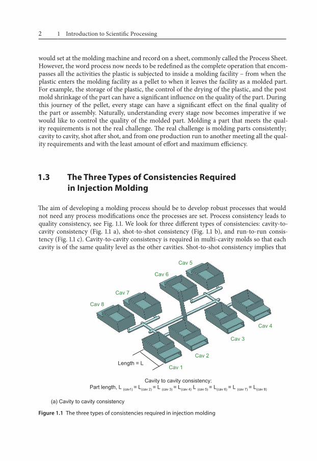
1.3 The Three Types of Consistencies Required in Injection Molding
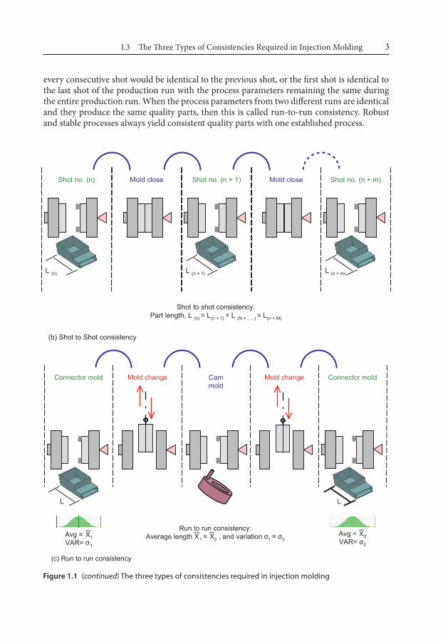
The aim of developing a molding process should be to develop robust processes that would not need any process modifications once the processes are set. Process consistency leads to quality consistency, see Fig. 1.1. We look for three different types of consistencies: cavity-to-cavity consistency (Fig. 1.1 a), shot-to-shot consistency (Fig. 1.1 b), and run-to-run consis-tency (Fig. 1.1 c). Cavity-to-cavity consistency is required in multi-cavity molds so that each cavity is of the same quality level as the other cavities. Shot-to-shot consistency implies that
Figure 1.1 The three types of consistencies required in injection molding
1.3 The Three Types of Consistencies Required in Injection Molding 3
every consecutive shot would be identical to the previous shot, or the first shot is identical tothe last shot of the production run with the process parameters remaining the same duringthe entire production run. When the process parameters from two different runs are identicaland they produce the same quality parts, then this is called run-to-run consistency. Robustand stable processes always yield consistent quality parts with one established process.
Figure 1.1 (continued) The three types of consistencies required in injection molding
1 Introduction to Scientific Processing4
1.4 Scientific Processing
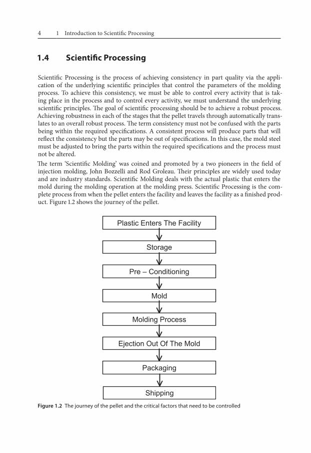
Scientific Processing is the process of achieving consistency in part quality via the appli-cation of the underlying scientific principles that control the parameters of the molding process. To achieve this consistency, we must be able to control every activity that is tak-ing place in the process and to control every activity, we must understand the underlying scientific principles. The goal of scientific processing should be to achieve a robust process. Achieving robustness in each of the stages that the pellet travels through automatically trans-lates to an overall robust process. The term consistency must not be confused with the parts being within the required specifications. A consistent process will produce parts that will reflect the consistency but the parts may be out of specifications. In this case, the mold steel must be adjusted to bring the parts within the required specifications and the process must not be altered. The term ‘Scientific Molding’ was coined and promoted by a two pioneers in the field of injection molding, John Bozzelli and Rod Groleau. Their principles are widely used today and are industry standards. Scientific Molding deals with the actual plastic that enters the mold during the molding operation at the molding press. Scientific Processing is the com-plete process from when the pellet enters the facility and leaves the facility as a finished prod-uct. Figure 1.2 shows the journey of the pellet.
Figure 1.2 The journey of the pellet and the critical factors that need to be controlled
1.5 The Five Critical Factors of Molding 5
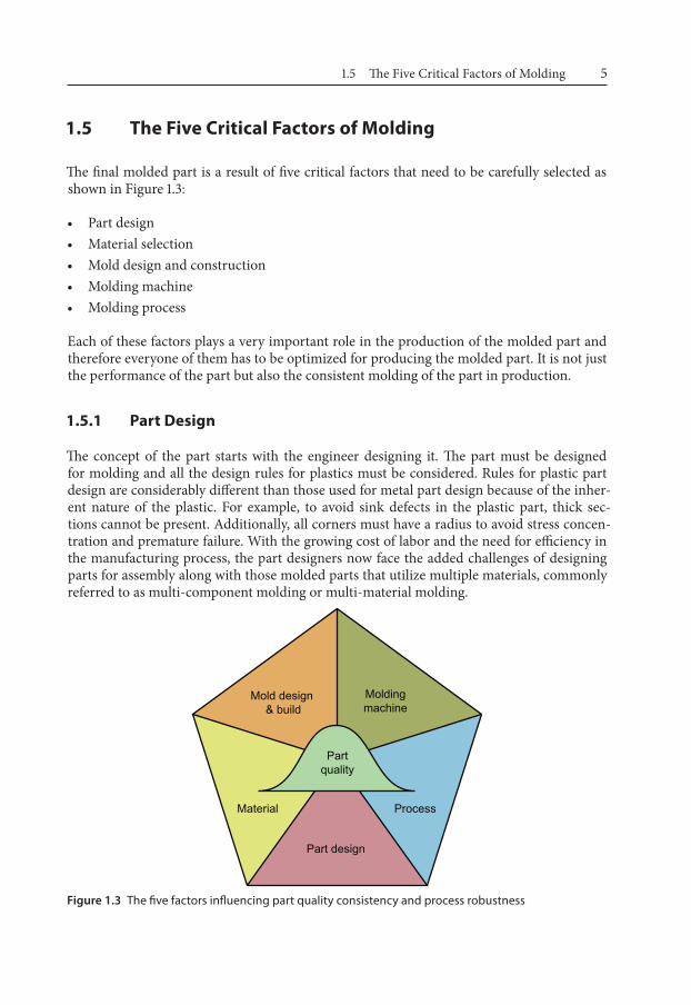
1.5 The Five Critical Factors of Molding
The final molded part is a result of five critical factors that need to be carefully selected as shown in Figure 1.3:
• Part design• Material selection• Mold design and construction• Molding machine• Molding process
Each of these factors plays a very important role in the production of the molded part and therefore everyone of them has to be optimized for producing the molded part. It is not just the performance of the part but also the consistent molding of the part in production.
1.5.1 Part Design
The concept of the part starts with the engineer designing it. The part must be designed for molding and all the design rules for plastics must be considered. Rules for plastic part design are considerably different than those used for metal part design because of the inher-ent nature of the plastic. For example, to avoid sink defects in the plastic part, thick sec-tions cannot be present. Additionally, all corners must have a radius to avoid stress concen-tration and premature failure. With the growing cost of labor and the need for efficiency in the manufacturing process, the part designers now face the added challenges of designing parts for assembly along with those molded parts that utilize multiple materials, commonly referred to as multi-component molding or multi-material molding.
Mold design & build
Moldingmachine
Process
Part design
Material
Partquality
Figure 1.3 The five factors influencing part quality consistency and process robustness
1 Introduction to Scientific Processing6
1.5.2 Material Selection
Based on the part design and the part performance requirements, the plastic material must be selected. In addition, the part design may require a special plastic material or a special additive to be added to the base plastic for performance. If a thick section must be present, a filled material may need to be selected or if there is a sliding surface, then an additive reducing the coefficient of friction may need to be added to the plastic. Material selection should typically be done when the basic part design is done. Additional smaller changes can be done concurrently.
1.5.3 Mold Design and Construction
Once the part design and material selection is complete, the mold must be designed and constructed such that it is robust enough to withstand the molding process and the plas-tic material. For example, during the molding process, the mold can be subjected to high mechanical stresses, especially during the plastic injection and the packing phases. The gates are high-wear areas and there are several places where the air needs to vent out for the plas-tic to enter the mold. Some plastic materials will require special attention and the mold must be specifically designed with the material in mind. Shrinkage may vary considerably from material to material. All these material specific factors must be considered. The required number of parts over the life of the mold is another factor that will dictate the actual mate-rials of construction. Wear on the mold components must be considered, as the materials chosen to build the injection mold and mold cavities will impact the overall life of the mold and associated amount of maintenance required to keep it production worthy.
1.5.4 Machine Selection
Selecting the right machine for the mold should be done once the mold design is complete. It can be done concurrently during the mold construction stage. The machine plays a very important role in the stability of the molding process. For example, machines with large shot sizes must not be used to mold small shots because the part quality consistency will suffer. Vice versa, using a large percentage of the shot size can give rise to problems with melt homogeneity and therefore issues with fill and dimensions. Small molds must also not be mounted in large machines for fear of mold damage due to excessive clamp tonnage being applied.
1.5.5 Molding Process
Process optimization is the last step before the mold is released into production. This book will cover this topic in detail. If the above four factors and activities are not properly selected or performed, process optimization can be a challenge, if not impossible, without incurring significant cost and delay to the project. At this stage, it is usually very late in the project timeline to make any changes to the part design or mold design, especially because of the cost and time involved. An improperly constructed mold can have a very narrow process

1.6 Concurrent Engineering 7
window leading to a process that will tend to be unstable. If the material selected is not capable of holding the tolerances, no process will be able to produce satisfactory parts.
1.6 Concurrent Engineering
There are various departments involved in the production of the molded part and therefore regular meetings between the different departments must be held. Each department will have specific knowledge of the selection process and can contribute not just to the process but more importantly predict issues once the mold comes over to their department. For exam-ple, getting the process engineer involved in a mold design can help in part orientation in the mold for easy removal, or the mold maker can get help with vent locations based on the process engineer’s experience. Involving the quality engineer can help the process engineer understand the required tolerances in the design stage. If the tolerances seem to be unre-alistic, they can go back to the product designer for wider tolerances or a material change. There are a lot of benefits associated with implementing concurrent engineering in injec-tion molding. A section is devoted to this topic in this book. In the chapters that follow, the reader will be introduced to the underlying scientific principles to achieve a robust molding process. This understanding will then help in the application of these principles, to develop a robust process and to troubleshoot problems that occur in production. The chapters have been written in a logical sequence to build the readers’ knowledge as one would require it or should learn it. However, if the reader is familiar with the topic, he or she can bypass some in favor of other chapters containing the desired information.
Suggested Further Reading
1. Osswald, T.A., Turng, L., Gramann, P.J. (Eds.), Injection Molding Handbook (2007) Hanser, Munich
2. Kulkarni, S.M., Injection Molding Magazine (June 2008) Cannon Publications, Los Angeles, USA
251Subject Index
Subject Index
AABS 69acetal 73acrylate 69acrylics 72acrylonitril 69addition polymerization 9additives 74aesthetic process window (APW) 129, 169, 170,
172, 177alarm limits 166aliasing 156, 157alloys 68amorphous 15
plastics – 103polymers – 12
anisotropic material 24anti-aging additives 75apparent shear rate 32apparent viscosity 27array – orthogonal 152atactic 13, 14
Bback pressure 109, 110, 137balanced array 152barrel clearance 83barrel heat profile 18Beaumont Technologies 38black specs 192blowing agents 76Box-Behnken design 152brittle parts 192bubbles 45, 192built-in stress 139burn marks 46, 192butadiene 69
Ccapillary rheometer 40cavity balance 120, 122
procedure – 121study – 118
cavity imbalance 123cavity pressure 118, 119
curve near the gate – 214sensing – 213sensor – 219
cavity pressure curve at the end of fill 215cavity steel adjustment 165chain scission 75characterization of polymer viscosity 40check ring 87clamp force 82, 90clamp tonnage 88, 90classification of polymers 67coefficient of friction 75colorants 76commercial plastics 68common defects – cause 193common defects – prevention 193composite dimensional process window 174concurrent engineering 7, 223condensation polymerization 9confounding 156, 157consistency 95
cavity to cavity – 2quality – 2run to run – 3shot to shot – 2
constant factors 149contact type probes 121contamination 192contour cooling 196contour plot 162, 163control factors 149control process window (CPW) 130, 171, 172,
177control sensor 217coolant – type of 197cooling line 195, 196cooling phase 104cooling time 19, 135, 136
optimization – 136study – 135
cooling variations 120
252 Subject Index
copolymers 68critical dimension 164critical factors of molding 5crystalline 15
polymers – 12, 103crystallinity 14, 23crystallite 12crystallization 75, 104
temperature – 18, 22cushion value 117cycle time 137
break-down – 137cyclone separator 207
Ddecoupled moldingSM 106, 107, 219degradation 45, 185degree of crystallinity 12, 13desiccant dryer 53design of experiments 145, 154
definition – 147dew point 52, 56dialatent 29dieseling effect 198differential scanning calorimeter (DSC) 22dimensional process window (DPW) 130, 162,
171, 172, 177dimensional variation 46dimensions out of specifications 192DIOP 74direct sensor 215dispersive mixing 85distributive mixing 85documentation books 183DOE, see design of experimentsdrying
equipment – 53of plastics – 50precautions – 101temperature – 50, 51time – 50, 51, 100, 205
Eeffect of regrind 210elastomers 68electronic moisture analyzer 55end-chain degradation 45end-of-fill cavity pressure integral 220
epoxidized soybean oil (ESO) 74
Ffactor 149, 150, 151, 162factorial experiments 145, 159family molds 123feed depth 84filler 74
content – 138fill pattern 123fill progression 117fines 206flame retardants 74, 75flash 120, 191flow
channel variations – 120front – 30imbalance – 35laminar – 196promoters – 76transitional – 196turbulent – 196, 197
fluoropolymers 73flush mount sensor 215forced venting 204fountain flow 30, 118free radicals 75free state 25full factorial experiment 159
Ggage reproducibility & repeatability 228gassing – excessive 186gate freeze study 133gate seal 133
cautions and exceptions – 135procedure – 133study – 132time – 134
general purpose polystyrene (GPPS) 82general purpose screw 84glass transition temperature 20glassy state 32
Hheater bands 83heat history 205heat soaking 183
253Subject Index
helix angle 86high-shear lamina 36‘High Temperature – High Pressure’ corner 130‘High Temperature – Low Pressure’ corner 130holding phase 104, 105, 106holding pressure 106, 128, 129holding time 128homopolymers 68horizontal clamp molding machine 80horizontal injection machine 81hot air dryer 53hump profile 103hydraulic ‘fill only’ integral 219hydraulic pressure curve 213hydrolytic degradation 45, 99hydrophilic 43hydrophobic 43hygroscopic 43, 48
Iindirect sensor 216injection
molding cycle – 104molding – parameter – 145phase – 104, 105, 106speed – 105
injection force 105in-mold rheology study 112inorganic polymers 67intensification ratio (IR) 87, 88, 108
of the screw – 83interaction 154, 156
column – 156types of – 155
intermolecular forces 11, 20internal voids 106isotropic material 24
KKarl-Fischer titration 55knowledge base 221
Llaminar flow 36L/D ratio 83, 86level 150linear response 145lot-to-lot variations 112
lower specification limit (LSL) 97, 164lower tolerance 142‘Low Temperature – High Pressure’ corner 130‘Low Temperature – Low Pressure’ corner 130lubricants 75
Mmachine selection 6, 88machine specifications 82material purging instructions 183material selection 5, 6material supplier – concurrent involvement 227material supplier – conventional
involvement 227maximum moisture level 43MeltFlipper® 38melt flow index (MFI) 41melt flow rate (MFR) 41melt homogeneity 19, 83melting point 21melt processing range 16, 17melt processing window 21melt pyrometer 102melt rheology 40melt rotation technology 38, 39melt temperature 17, 21, 102, 129melt viscosity reducers 76moisture determination 54mold cooling 195mold design and construction 5, 6mold designer – concurrent involvement 226mold designer – conventional involvement 226molded-in stress 106mold filling speed 17mold function qualification 177
procedure – 141mold height 89molding area diagram 129, 131molding machine 5
classification – 79molding process 5, 6
effect on the part properties – 205molding shut down 187molding startup 186mold length 88mold maker – concurrent involvement 226mold maker – conventional involvement 226mold open stroke 89
254 Subject Index
mold qualificationbook – 183checklist – 143, 179flowchart – 177
mold shut-down procedure 183mold stack height 88mold temperature 17, 103, 104, 129
map – 182mold width 88molecular weight 10, 14, 206
distribution (MWD) – 10, 11monitor sensor 217morphology 12
role of – 16multiple cavities 175multi-shot machine 81
Nnatural cause variations 95“naturally balanced” runner 37Newtonian 29noise factors 149nominal dimension 142non-Newtonian 29, 67non-return valve 87nozzle drool 47nozzle temperature control 19nucleating agents 75number average molecular weight 10number of experiments 151nylon overdrying 60
Ooperating process window 167operator instructions 183optical clarity 20organic polymers 67orthogonal array 153, 154Ostwald and de Waale 30out of specifications 97oven dryers 53overdrying 44, 56
controller – 63prevention – 63
Ppacking phase 104–106packing pressure 118, 128
packing time 128parallel cooling 197Pareto chart 161part design 5partial factorial experiment 159parting line shot 81parting line vent 204part quality qualification 177PBT overdrying 57percentage shot size used 91phthalates 74piezoelectric sensor 215Plackett-Burman design 152plasticating capacity 83plastic drying 43, 99plasticizers 74plastic pressure 83platen 88
deflection – 89plugging up of the vents 46Poisson’s effect 25polar group 49, 50polyamides 70polycarbonates 72polyesters 72polyethylene 69polymer 9
blends – 76crystallinity – 14morphology – 123rheology – 27
polyolefins 68polyoxymethylene 73polypropylene 69polystyrenes 71polyvinyl chloride 72post-gate cavity pressure integral 220post-molding shrinkage 106, 138prediction equation 162pressure drop 124, 126, 127
studies – 124study – procedure – 125
pressure graph 217pressure limited 124, 125, 127pressure limited process 105pressure sensor 215process change log 180
sheet – 189
255Subject Index
process consistency 2, 96, 142process documentation 143, 180process engineer – concurrent requirement 227process engineer – conventional
involvement 227processing aids 76process optimization 110process robustness 96, 142process selection 165process sensitivity chart 164process sheet 180process window 129, 131, 162
cautions and exceptions – 132crystalline materials – 131study – 128study procedure – 130
product designer – conventional involvement 225
product designer – required involvement 225production book 183, 189purging 185
compound – 187PVT graph 145, 146, 147
Qqualification runs 183qualifications 190qualitative factor 149quantitative factor 149quartz-based sensor 215
Rracetrack effect 37randomization 158, 159reducing inspection 167regrind 205
batch process – 207continuous process – 207generation estimating – 208generation number – 206molecular weight – 210particle size distribution – 206processing – 207
relative humidity 52residence time 92resin storage 99response 149, 150, 162
qualitative – 150
quantitative – 150Reynolds number 196, 197rheological behavior 110rheological flow variations 120rheological imbalance 37, 123rheology study 110
cautions and exceptions – 116procedure – 114
robust process 95, 97, 98, 99, 162development – 104
runner – venting 203
Sscientific molding 4, 95scientific processing 95
definition – 4screening experiment 152screw 83
bounce-back – 117channel depth – 84compression ratio – 85compression zone – 84designs – 86diameter – 83feed zone – 84metering zone – 85outside diameter – 84recovery speed – 19recovery time – 108, 110root diameter – 84slipping – 84speed – 108, 137transition zone – 84
semi-crystalline 12sensor 213
locations – 221series cooling 197setup instructions 182shear energy 108shear force 28shear friction 19shear heat 83shear rate 28, 29, 31, 40, 112shear rate profile 33, 34, 35shear stress 29shear thinning 29, 67shelf life limitations 99short shot 120, 126, 191, 198
256 Subject Index
shot control 48shot size 82, 85, 91, 92shot-to-shot inconsistency 192shrinkage 16, 23, 25, 118, 138, 139
additives – 138annealing – 139filler – 138glass transition temperature – 138measuring procedure – 139mold temperature – 139part thickness – 139processing conditions – 139rate of – 138
sink 106, 191solution rheology 40special cause variations 95specifications 95specific volume 21, 118splay 45, 191startup procedure 186statistical analysis 160statistical data 152stereoregular 12strain gage sensor 215streaks 192stress build-up 37styrene 69surface defects 45switch-over point 117syndiotactic 13, 14
TTaguchi design 152target dimension 162Teflon 73tensile properties 68thermal imaging system 121thermal region 32thermal transition 20, 22thermoplastics 67thermosets 67Thomasetti Volatile indicator test 54toggle machine 89tolerance limit 167tolerances – process change 166tonnage 82, 90tonnage calculation 91
tooling engineer – concurrent requirement 226tooling engineer – conventional
involvement 226tornado chart 161, 162troubleshooting 187, 190troubleshooting – guideline 185, 188, 191, 192TVI Test 54
Uupper specification limit (USL) 97, 164upper tolerance 142UV stabilizers 75
Vvacuum assist 204vacuum venting 204valve gate mold 204velocity 34
profile – 33, 35vent
depth – 201dimensions – 200locations – 203reliefs – 200size – 202
venting 198variations – 120
vertical clamp molding machine 80vertical injection 81virgin material 205viscosity 11, 17, 27, 31, 32, 105, 110, 112
curve – 113curve worksheet – 115effect of temperature on – 32in polymer melts – 30linear scale – 111logarithmic scale – 111model – 40
voids 192volumetric shrinkage 106
Wwarpage 106, 139, 191waterline diagram 181water lines 197weld line 47Wheatstone bridge 215