
SAINT GEORGE, ALASKAdec.alaska.gov/water/vsw/ProjectSites/stgeorgeProject/pdfs/2010... · SAINT...
90
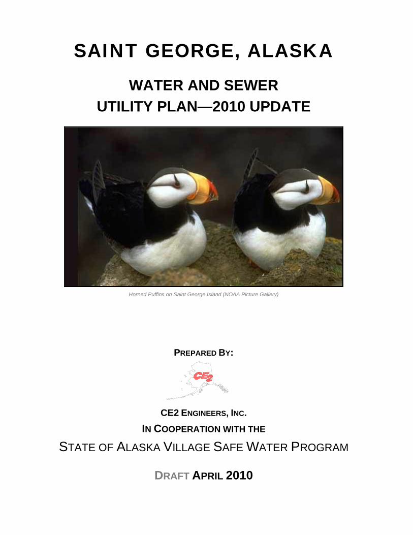
SAINT GEORGE, ALASKA WATER AND SEWER UTILITY PLAN—2010 UPDATE Horned Puffins on Saint George Island (NOAA Picture Gallery) PREPARED BY: CE2 ENGINEERS, INC. IN COOPERATION WITH THE STATE OF ALASKA VILLAGE SAFE WATER PROGRAM DRAFT APRIL 2010
Transcript of SAINT GEORGE, ALASKAdec.alaska.gov/water/vsw/ProjectSites/stgeorgeProject/pdfs/2010... · SAINT...
SAINT GEORGE, ALASKA
WATER AND SEWER UTILITY PLAN—2010 UPDATE
Horned Puffins on Saint George Island (NOAA Picture Gallery)
PREPARED BY:
CE2 ENGINEERS, INC.
IN COOPERATION WITH THE
STATE OF ALASKA VILLAGE SAFE WATER PROGRAM
DRAFT APRIL 2010

2010 Draft Water & Sewer Utility Plan Update Saint George, Alaska
Draft Update: April 2010 i
Table of Contents
I. CONCLUSIONS AND RECOMMENDATIONS ..................................................... 1
A. Overview and Alternative Selected by the Community ..................................................... 1 B. Conceptual Project Layout ................................................................................................ 2 C. Project Construction Phases, Including Units and Unit Costs for Each Phase ................. 3 D. Operation and Maintenance (O & M) Costs for All Alternatives ........................................ 3 E. Business Plan Summary ................................................................................................... 4
II. INTRODUCTION .................................................................................................. 5
III. PROJECT PLANNING AREA ............................................................................... 7
A. Location and Access ......................................................................................................... 7 1. Highway/Road System ................................................................................................ 7 2. Airport and Barge Service ........................................................................................... 7
B. Environmental Conditions or Resources Present ............................................................. 8 1. Climate ........................................................................................................................ 8 2. Geology and Soil Condition ......................................................................................... 8 3. Flood, Erosion, and Seismic Hazards ......................................................................... 9 4. Historic Sites ............................................................................................................. 10 5. Endangered Species and Critical Habitats ................................................................ 11
C. Economy and Financial Profile ........................................................................................ 11 D. Potential Growth Areas ................................................................................................... 12 E. Power Generation and Fuel Storage Facilities ................................................................ 12 F. Public Facilities and Housing .......................................................................................... 12 G. Public Administration ....................................................................................................... 13 H. Population ....................................................................................................................... 14
1. Present and Projected Population ............................................................................. 14 2. Number of Households to be Served ........................................................................ 15 3. Number of People Benefiting from Project ................................................................ 15
IV. FUTURE CAPITAL PROJECTS, COSTS AND SCHEDULES ........................... 16
A. Roads, Airports and Ports ............................................................................................... 16 B. Power Generation and Fuel Storage Facilities ................................................................ 16 C. Community Facilities ....................................................................................................... 16 D. School and Head Start .................................................................................................... 16 E. Health Clinic .................................................................................................................... 17 F. Commercial Facilities ...................................................................................................... 17
V. EXISTING WATER & SEWER FACILITIES AND PLANNING CONDITIONS .... 18
A. Project Planning Area Map ............................................................................................. 18

2010 Draft Water & Sewer Utility Plan Update Saint George, Alaska
Draft Update: April 2010 ii
B. History of Sanitation Improvements ................................................................................ 18 C. Condition of Facilities ...................................................................................................... 29 D. Financial Status of Operating Facilities ........................................................................... 39
VI. LAND STATUS ................................................................................................... 40
A. Land Owners in Proposed Project Area .......................................................................... 40 1. Federal ...................................................................................................................... 40 2. State .......................................................................................................................... 40 3. Regional Land Corporation ....................................................................................... 40 4. Village Land Corporation ........................................................................................... 40 5. City or Tribal .............................................................................................................. 41 6. Native Allotments ...................................................................................................... 41 7. Homesteads .............................................................................................................. 41 8. Other Owners ............................................................................................................ 41 9. Existing Easements ................................................................................................... 42
B. Traditional Use Areas ...................................................................................................... 42 C. Land Conflicts that Could Affect the Project, Platting Status ........................................... 42 D. Proposed Solutions to Land Conflicts ............................................................................. 42
VII. NEED FOR PROJECT ....................................................................................... 43
A. Health and Safety Concerns ........................................................................................... 43 B. Environmental Concerns ................................................................................................. 43 C. System Growth Capacity ................................................................................................. 43
VIII. COMMUNITY CAPACITY .................................................................................. 44
A. Management Status ........................................................................................................ 44 B. Financial Status ............................................................................................................... 44 C. System Operation & Maintenance (O&M) Status ............................................................ 44
IX. SANITATION FACILITY ALTERNATIVES ......................................................... 46
A. Description ...................................................................................................................... 46 B. Design Criteria ................................................................................................................ 47 C. Conceptual Layout .......................................................................................................... 51 D. Unique Environmental Impacts ....................................................................................... 56 E. Land Requirements and Easements ............................................................................... 56 F. Construction Constraints ................................................................................................. 56 G. Impacts to Existing Infrastructure .................................................................................... 56
1. Roads ........................................................................................................................ 56 2. Electrical Power ......................................................................................................... 56 3. Bulk Fuel ................................................................................................................... 57
H. Cost Estimates ................................................................................................................ 57
2010 Draft Water & Sewer Utility Plan Update Saint George, Alaska
Draft Update: April 2010 iii
1. Construction Cost Estimate ....................................................................................... 57 2. Annual Operation and Maintenance Costs, Cost per Month per Household Served
and Cost per Month for Non-Residential Users ......................................................... 66 3. Life Cycle Costs ........................................................................................................ 66
I. Review of Operational Costs for Similar Systems within Region .................................... 67 J. Advantages and Disadvantages ..................................................................................... 67
X. PUBLIC PARTICIPATION IN THE PLANNING PROCESS ................................ 68
A. Methods Used to Gain Community Input and Direction .................................................. 68 B. Identification of Community Goals and Objectives .......................................................... 68
XI. COMMUNITY BUSINESS PLAN FOR SELECTED ALTERNATIVE .................. 69
XII. CONCLUSIONS AND RECOMMENDED ALTERNATIVE ................................. 70
A. Description of Recommended Alternative ....................................................................... 70 B. Capital Cost Estimate ...................................................................................................... 70 C. Estimated Annual Revenues and Revenue Sources ...................................................... 70 D. Annual Operation and Maintenance Costs ..................................................................... 71 E. Capital Cost per Home Served ....................................................................................... 71
List of Appendices
Appendix A – Community Resolution Accepting the Water & Sewer Utility Plan Update
Appendix B – Well Drilling Logs for Current Production Wells
Appendix C – Water Resources Reconnaissance--1976
Appendix D – Laboratory Analysis and Water Quality Data
Appendix E – Heterotrophic Plate Counts and Drinking Water Safety
Appendix F – Plan Update Contacts
Appendix G – Community Sanitary Survey—2006
Appendix H – Community Rates, Charges, Rules & Regulations
Appendix I – Business Plan After Proposed Improvements

2010 Draft Water & Sewer Utility Plan Update Saint George, Alaska
Draft Update: April 2010 iv
List of Figures Figure 1 Overall Map ............................................................................................. 19
Figure 2 Existing Water Distribution System .......................................................... 23
Figure 3 Existing Wastewater Collection System ................................................... 26
House Plumbing Key Map ....................................................................... 38
Figure 4 Proposed Water Distribution System Improvements ............................... 52
Figure 5 Proposed Wastewater Collection System Improvements ........................ 56
List of Tables Table 1 Power Generation .................................................................................... 12
Table 2 Bulk Fuel Storage Facilities ..................................................................... 12
Table 3 Housing Characteristics ........................................................................... 13
Table 4 General Municipal Information ................................................................. 13
Table 5 2000 U.S. Census Population .................................................................. 14
Table 6 U.S. Census Data .................................................................................... 14
Table 7 Design Population .................................................................................... 15
Table 8 Community Medical Facilities .................................................................. 17
Table 9 Active City Wells ...................................................................................... 21
Table 10 Sewer Main Condition Summary Report .................................................. 32
Table 11 Manhole Condition Summary Report ....................................................... 34
Table 12 House Plumbing Condition Summary Report .......................................... 35
Table 13 ANSCA Land Entitlement ......................................................................... 40
Table 14 Proposed Design Criteria ......................................................................... 47
Table 15 Study Level Cost Estimate—Summary .................................................... 58
Table 16 New Wells, Well Controls, Chlorination Equipment, Tank Recirc ............ 59
Table 17 Waterfront Street Intertie (Priority One) ................................................... 60
Table 18 Eliminate 50+ year-old Cast Iron Pipe (Priority Two) ............................... 61
Table 19 Replace main Feeder Line from Water Tank (Priority Three) .................. 62
Table 20 Choochie Heights Subdivision Loop (Priority Four) ................................. 63
2010 Draft Water & Sewer Utility Plan Update Saint George, Alaska
Draft Update: April 2010 v
Table 21 Insulate City Water Tank .......................................................................... 64
Table 22 Insulate Zapadni Bay Water Storage Tank .............................................. 65
Table 23 Sewer Collection & Disposal Improvements ............................................ 66
Table 24 Summary of Recommended Improvements (Phases) ............................. 67
2010 Draft Water & Sewer Utility Plan Update Saint George, Alaska
Draft Update: April 2010 vi
ACRONYMS AND ABBREVIATIONS ADEC Alaska Department of Environmental Conservation ANCSA Alaska Native Claims Settlement Act ANTHC Alaska Native Tribal Health Consortium APIA Aleutian Pribilof Islands Association APICDA Aleutian Pribilof Island Community Development
Association AVCP Association of Village Council Presidents BIA Bureau of Indian Affairs CDBG Community Development Block Grant CE2 CE2 Engineers, Inc. Cfu/mL Colony forming units per milliliter City City of Saint George OE U. S. Army Corps of Engineers Council Saint George City Council DCED Alaska Department of Community and Economic
Development DIP Ductile Iron Pipe DOT Alaska Department of Transportation & Public Facilities EACC Equivalent Annual Capital Cost EPA U.S. Environmental Protection Agency FEMA Federal Emergency Management Agency Gpcd Gallons per capita per day GPM Gallons per minute HPC Heterotrophic Plate Count HUD Housing and Urban Development LF Lineal Feet MCLs Maximum Contaminant Levels MCLGs Maximum Contaminant Level Goals MLLW Mean Lower Low Water NFS non-frost susceptible NMF National Marine Fisheries NOAA National Oceanic & Atmospheric Administration NPDES National Pollutant Discharge Elimination System O & M Operation and Maintenance PCS Petroleum Contaminated Soils PHS Public Health Service

2010 Draft Water & Sewer Utility Plan Update Saint George, Alaska
Draft Update: April 2010 vii
PVC Poly Vinyl Chloride R & R Repair & Replacement RMW Remote Maintenance Worker SHPO State Historical Preservation Office USDA United States Department of Agriculture USPHS United States Public Health Service VPSO Village Public Safety Officer VSW Village Safe Water WTP Water Treatment Plant

2010 Draft Water & Sewer Utility Plan Update Saint George, Alaska
Draft Update: April 2010 1
I. CONCLUSIONS AND RECOMMENDATIONS
A. Overview and Alternative Selected by the Community
Residents of the Pribilof Island Community of Saint George (pop. 152, 2000 U.S.
Census) have had piped water and sewer for over 60 years. The federal government
(National Marine Fisheries) installed a then state-of-the-art piped utility system in the
1940’s and 1950’s when Saint George was a “company town” in support of the federal
government’s fur sealing enterprise. Sealing was halted in 1983. The federal
government transferred the water and sewer system to the newly created City of Saint
George. As-built records didn’t exist or were never found.
Since that time the piped utility system has been expanded and/or repaired by the US
Public Health Service (1985-86) and the State of Alaska Village Safe Water Program
(1990-91). In addition, the City constructed a new 286,000-gallon water storage tank in
1999 and extended utilities to a new 6-plex in 2001.
In 2001, mounting maintenance and repair costs and general concern for the
deterioration of the water distribution piping and wastewater collection piping prompted
the City to contract with CE2 Engineers, Inc. (CE2) to undertake a program to locate,
map and evaluate the water distribution and wastewater collection systems in the City.
In-house plumbing was also evaluated. Funds for the work were provided and
administered by the State of Alaska Village Safe Water Program (VSW). Field
evaluation was completed in early September 2001. The report was completed the
same month and accepted by the City Council on November 9, 2001. The 2001 report
recommended replacement / reconfiguration of deteriorated portions of the distribution
and collection systems. This report updates the findings and estimated unit costs for the
distribution and collection system projects proposed in 2001, and adds supply and
storage upgrades that are urgently needed to reduce the potential for continued
bacteriological contamination and to conserve the very limited water supply resource.
These tasks provide level control for the wells to eliminate the frequent pump burn-ups,
recommends additional well development, chlorination of the water supply to mitigate
the pseudomonas bacteria contamination, insulation of the bolted bare steel water
2010 Draft Water & Sewer Utility Plan Update Saint George, Alaska
Draft Update: April 2010 2
tanks, continuous mixing of the water in the city water storage tank to reduce freezing
potential and replacement of the distribution and collection piping as recommended in
2001. The recently identified bacterial contamination (a strain of pseudomonas bacteria
continues to persist in water samples) requires these upgrades to provide a safe water
supply.
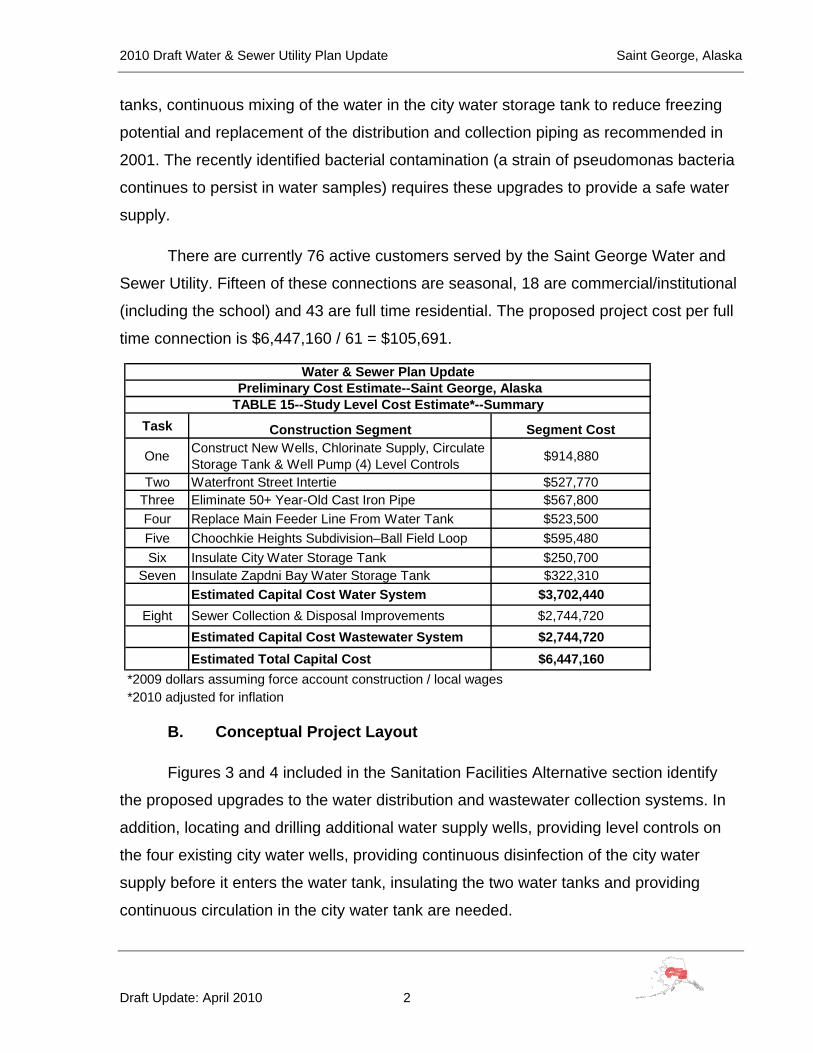
There are currently 76 active customers served by the Saint George Water and
Sewer Utility. Fifteen of these connections are seasonal, 18 are commercial/institutional
(including the school) and 43 are full time residential. The proposed project cost per full
time connection is $6,447,160 / 61 = $105,691.
Task Construction Segment Segment Cost
One Construct New Wells, Chlorinate Supply, Circulate Storage Tank & Well Pump (4) Level Controls $914,880
Two Waterfront Street Intertie $527,770Three Eliminate 50+ Year-Old Cast Iron Pipe $567,800Four Replace Main Feeder Line From Water Tank $523,500Five Choochkie Heights Subdivision–Ball Field Loop $595,480Six Insulate City Water Storage Tank $250,700
Seven Insulate Zapdni Bay Water Storage Tank $322,310Estimated Capital Cost Water System $3,702,440
Eight Sewer Collection & Disposal Improvements $2,744,720Estimated Capital Cost Wastewater System $2,744,720Estimated Total Capital Cost $6,447,160
*2009 dollars assuming force account construction / local wages
Water & Sewer Plan Update Preliminary Cost Estimate--Saint George, AlaskaTABLE 15--Study Level Cost Estimate*--Summary
*2010 adjusted for inflation
B. Conceptual Project Layout
Figures 3 and 4 included in the Sanitation Facilities Alternative section identify
the proposed upgrades to the water distribution and wastewater collection systems. In
addition, locating and drilling additional water supply wells, providing level controls on
the four existing city water wells, providing continuous disinfection of the city water
supply before it enters the water tank, insulating the two water tanks and providing
continuous circulation in the city water tank are needed.

2010 Draft Water & Sewer Utility Plan Update Saint George, Alaska
Draft Update: April 2010 3
A system wide open bore flushing of the storage and distribution system will
reduce the build-up of deposited organic and corrosion debris which provide an
environment for bacteria to grow. This will require digging up the dead end mains and
opening the ends to provide adequate flushing velocities. This level of effort is beyond
the financial and technical resources of the available onsite maintenance staff.
C. Project Construction Phases, Including Units and Unit Costs for Each Phase
The improvements are planned to be constructed in two phases. Phase I
($2,971,860) will be the construction of the water system improvements and Phase II
($2,465,620) will be the construction of the sewer system improvements. Units and unit
costs are detailed in the Sanitation Facilities Alternative section.
Given the recently quantified (September 2006 through March 2007) bacterial
contamination of the water system and the more recent problems with the distribution
system (January 2007) causing the city water tank to completely empty, improvements
to the water system are urgently needed.
Wastewater collection system improvements are also critical. The evaluation
revealed collapsed manholes, fractured pipes, settled lines, etc.
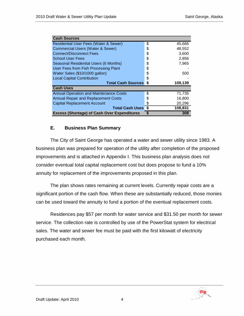
D. Operation and Maintenance (O & M) Costs for All Alternatives
The annual estimated cash flow after the proposed system improvements is
approximately $110,000. A portion of these costs will be offset by the avoided cost of
repairing a system that is rapidly heading toward complete failure and by the
communal benefit of enhanced fire protection.
2010 Draft Water & Sewer Utility Plan Update Saint George, Alaska
Draft Update: April 2010 4
E. Business Plan Summary
The City of Saint George has operated a water and sewer utility since 1983. A
business plan was prepared for operation of the utility after completion of the proposed
improvements and is attached in Appendix I. This business plan analysis does not
consider eventual total capital replacement cost but does propose to fund a 10%
annuity for replacement of the improvements proposed in this plan.
The plan shows rates remaining at current levels. Currently repair costs are a
significant portion of the cash flow. When these are substantially reduced, those monies
can be used toward the annuity to fund a portion of the eventual replacement costs.
Residences pay $57 per month for water service and $31.50 per month for sewer
service. The collection rate is controlled by use of the PowerStat system for electrical
sales. The water and sewer fee must be paid with the first kilowatt of electricity
purchased each month.
Cash SourcesResidential User Fees (Water & Sewer) 45,666$ Commercial Users (Water & Sewer) 48,552$ Connect/Disconnect Fees 3,600$ School User Fees 2,856$ Seasonal Residential Users (6 Months) 7,965$ User Fees from Fish Processing Plant -$ Water Sales ($10/1000 gallon) 500$ Local Capital Contribution -$
Total Cash Sources 109,139$ Cash UsesAnnual Operation and Maintenance Costs 71,735$ Annual Repair and Replacement Costs 16,800$ Capital Replacement Account 20,296$
Total Cash Uses 108,831$ Excess (Shortage) of Cash Over Expenditures 308$

2010 Draft Water & Sewer Utility Plan Update Saint George, Alaska
Draft Update: April 2010 5
II. INTRODUCTION
Saint George was discovered in 1786 by Gavrill Pribilof of the Russian Lebedov
Lastochkin Company while looking for the famed northern fur seal breeding grounds.
The island was named Sveti Georgiy, and its larger neighbor to the north was originally
called St. Peter and St. Paul Island. The Russian American Company enslaved Aleut
hunters from Siberia, Unalaska, and Atka and relocated them to Saint George and St.
Paul to harvest the fur seal. Between 1870 and 1910, the U.S. Government leased the
Pribilof Islands to private companies, who provided housing, food, and medical care to
the Aleuts in exchange for work in the fur seal plant. In 1910, the U.S. Bureau of
Fisheries took control of the Islands, but poverty conditions ensued due to over-
harvesting of the seals. During World War II, residents were moved to Funter Bay in
Southeast Alaska as part of the area wide evacuation. Unlike other Aleutian residents,
they were confined in an abandoned cannery and mine camp at Funter Bay. In 1979,
From NOAA Picture Gallery

2010 Draft Water & Sewer Utility Plan Update Saint George, Alaska
Draft Update: April 2010 6
the Pribilof Aleuts received $8.5 million in partial compensation for the unfair and unjust
treatment they were subjected to under federal administration between 1870 and 1946.
In 1983, the U.S. government ended the commercial seal harvest and withdrew from the
Islands, providing $20 million to help develop and diversify the local economy - $8
million for Saint George and $12 million for St. Paul. The City was incorporated in 1983.
Residents continue working to develop commercial fisheries and tourism. (Alaska
Department of Community and Economic Development).
This report will summarize the results of the planning efforts, present background
information, overview existing efforts in water supply, storage, treatment and distribution
and wastewater collection and treatment, and present recommendations for future
course(s) of action.

2010 Draft Water & Sewer Utility Plan Update Saint George, Alaska
Draft Update: April 2010 7
III. PROJECT PLANNING AREA
A. Location and Access
The City of Saint George is located on the northeast shore of Saint George
Island, the southern-most of five islands in the Pribilofs. It lies 47 miles south of Saint
Paul Island, 750 air miles west of Anchorage and 250 miles northwest of Unalaska. It
lays at approximately 56° 36’ North Latitude, 169° 32’ West Longitude. (Section 29,
Town 41 South, Range 129 West, Seward Meridian) Saint George is located in the
Aleutian Islands Recording District. (Alaska Department of Community and Economic
Development).
1. Highway/Road System
An internal road system exists that serves properties in the City proper
and an approximately five mile long road from the City to Zapadni Bay provides
the connection to the harbor facilities on the south side. The newly constructed
City landfill is located on a spur off the harbor road, near the middle of the island.
2. Airport and Barge Service
Saint George is accessible only by air and sea. The airport is owned by
the State of Alaska, Department of Transportation & Public Facilities, with a
5,000' long by 150' wide newly paved runway. Scheduled passenger flights are
provided to St. Paul and the mainland three days per week, weather permitting.
Airfreight operates on a daily basis, weather permitting. Freight and supplies are
delivered by ship from Anchorage on an intermittent schedule. Barge traffic from
Seattle occurs as adequate amounts of freight are contracted for movement. An
inner harbor and dock handle incoming boat traffic in Zapadni Bay, 5 miles from
the City (Alaska Department of Community and Economic Development).

2010 Draft Water & Sewer Utility Plan Update Saint George, Alaska
Draft Update: April 2010 8
B. Environmental Conditions or Resources Present
1. Climate
The cold waters of the Bering Sea control the climate of Saint George.
The maritime location results in cool weather year round, and a narrow range of
mean temperatures varying from 24 to 52 degrees Fahrenheit. Average
precipitation is 23 inches, with 57 inches of snowfall. The maritime location
results in cool weather year round. Cloudy, foggy weather is common during
summer months. (Alaska Department of Community and Economic
Development)
2. Geology and Soil Condition
Saint George Island, Pribilof Islands, Alaska, is a late Cenozoic
(approximately 2.2-1.6 Million Years ago (Ma)) volcanic center located on the
southern edge of the Bering Sea shelf. The island is largely composed of layered
basaltic lava flows and eroded cinder cones. Lava flows on Saint George have
been offset by major extensional faulting that generally steps down to the north
from the east-northeast trending Ulakaia fault, which spans the island. The City
of Saint George, on the northern shore of the island, is located on an eroded and
faulted cinder cone complex. The complex, which appears to have erupted from
two separate vents, is primarily composed of scoria with intercalated lenses of
lava and ash.
Groundwater on an oceanic island of uniform geology generally occurs as
a freshwater lens above saline water, formed by the radial movement of
freshwater moving toward the coast. Groundwater on Saint George Island occurs
as a relatively thin (approximately 2.0') freshwater lens, primarily within basalts
with varying lithological and hydraulic characteristics; the secondary porosity is
generally high due to the layering of the flows, scoria interbeds and the presence
of cooling fractures. In the northern portion of the island, groundwater is tidally-
influenced; the mean hydraulic gradient was calculated using a filtering method

2010 Draft Water & Sewer Utility Plan Update Saint George, Alaska
Draft Update: April 2010 9
which effectively removes all diurnal and semi-diurnal lunar and solar harmonics
from consecutive hourly water level observations. Groundwater flow in the vicinity
of Saint George village is most likely controlled by the east-west trending normal
faults that locally increase the hydraulic conductivities of the basalts and may
provide preferential flow paths to the sea. (The Geological Society of America
(GSA), Heather K. Vick, Tetra Tech EM Inc).
3. Flood, Erosion, and Seismic Hazards
The U.S. Army Corps of Engineers Flood Plain Management Services
indicates no detailed flood elevation studies and no known flooding events. The
City of Saint George is not a participating member of the National Flood
Insurance Program (NFIP).
Seismic hazards (Damage due to earthquakes) are predicted to be
relatively moderate for the Pribilof Islands. The ground shaking produced by an
earthquake is actually very complex (hard, gentle, long, short, jerky or rolling)
and not describable with one number. Motions are described by the PEAK
VELOCITY (how fast the ground is moving); PEAK ACCELERATION (how
quickly the speed of the ground is changing); FREQUENCY (energy is released
in waves and these waves vibrate at different frequencies just like sound waves);
and DURATION (how long the strong shaking lasts).
From Section 1615 in the 2000 International Building Code, as adopted by
the State of Alaska, the following seismic design parameters are applied to
construction at Saint George. Site Class D: This site class relates to the soil
profile, which is a stiff soil. This type of soil lies between Class C (very dense soil
and soft rock) and Class E (soft soil profile). 1.75 G for 0.2 sec spectral response
acceleration (Sds). G is the force of gravity (an acceleration of 32 feet/second2).
When there is an earthquake, the forces caused by the shaking can be
measured as a percentage of the force of gravity. Spectral acceleration (SA) is
what is experienced by a particle on the ground. The design of a building must be
able to withstand 175% of G for 0.2 of a second (short period response). 0.60 G

2010 Draft Water & Sewer Utility Plan Update Saint George, Alaska
Draft Update: April 2010 10
for 1.0 sec spectral response acceleration (Sdl): The design of a building must
be also able to withstand 60% of G for 1.0 second (long spectral response).
Erosion potential of soils with the organic mat intact is minimal; without the
organic mat, soil erosion potential by water is moderate and by wind is severe.
4. Historic Sites
Saint George Sealing Plant Restoration Project
The United States acquired Saint
George Island, one of the Pribilof Islands,
when Alaska was purchased from Russia in
1867. From 1867 to 1910, private
companies, under contract to the United
States government, ran the harvest of
Northern Fur Seals and a pelt processing
operation on Saint George. Then, in 1910,
the federal government became the sole
administrator and operator of the Saint
George fur seal operation. This continued
until 1983, when the federal government
withdrew its operations from Saint George Island.
The sealing plant was used to process sealskins and render remains, as
part of the lucrative commercial seal harvest, which peaked from the 1940s
through the 1960s. This sealing plant, the last one of its kind still in existence,
was designated to the National Register of Historic Places in 1986. By the late
1990s, the building was disintegrating from the combined attack of salt, water,
and frosts and was in danger of collapse and being lost forever.
In 1998, NOAA, working with federal, state, local and tribal partners,
began restoration of the structure in order to slow its deterioration and preserve it
for future use. Working with the local Native Corporation, NOAA completed
A historic sealing plant on Saint George Island in Alaska before and after NOAA oversaw its
restoration in 1998-99. Photo: NOAA.

2010 Draft Water & Sewer Utility Plan Update Saint George, Alaska
Draft Update: April 2010 11
structural repairs and restoration of the Saint George Sealing Plant building on
Saint George Island, Alaska.
The Saint George community and Tribal members did most of the work.
The project was completed in November of 1999. Possessing the heritage of the
commercial seal harvest, and as current stewards of the Northern Fur Seal
population, NOAA is proud to help preserve this historic resource. Several
options are being considered for the future use of the former Sealing Plant,
including the development of a museum and interpretive center. (www.noaa.gov).
5. Endangered Species and Critical Habitats
The Island of Saint George, along with a 20-nautical-mile area
surrounding the Island, has been designated as a critical habitat for Stellar Sea
Lions. In 1990 the Stellar Sea Lion was placed on the U.S. Endangered Species
List. Over 210 species of birds nest on the cliffs of Saint George Island. Saint
George is one of the largest seabird breeding colonies in the Northern
Hemisphere.
C. Economy and Financial Profile
The Federally-controlled fur seal industry dominated the economy of the Pribilofs
until 1983; the two communities (Saint George and St. Paul) remain closely tied. Most
employment is in government positions and commercial fishing. Eleven residents hold
commercial fishing permits for halibut. Puffin Seafoods, a small halibut freezing facility,
opened in summer 1998 but has since closed. Floating crab processors operate
seasonally in the Saint George harbor. Saint George harvests 200 fur seals each year
for subsistence purposes. Halibut, reindeer, marine invertebrates, plants, and berries
also contribute to the local diet. Saint George is predominantly Aleut. The Pribilof Island
seal population and the community's dependence on it has been a major influence on
the local culture. More than a million fur seals congregate on the islands every summer.
(Alaska Department of Community and Economic Development)
2010 Draft Water & Sewer Utility Plan Update Saint George, Alaska
Draft Update: April 2010 12
D. Potential Growth Areas
The geographic remoteness of Saint George Island limits the potential for
population growth. Limited employment opportunities exist. A limited amount of
buildable land area is available in the City to construct residential, commercial or
institutional structures should the need arise.
E. Power Generation and Fuel Storage Facilities
TABLE 1--Power Generation (Alaska Department of Community and Economic Development).
Electric Utility Name Saint George Municipal Electric Utility
Utility Operator City
Power Source Diesel
Kilowatt Capacity 605
Rate/Kilowatt Hour 20.1 cents/KWH
Power Cost Equalization (PCE) Subsidy No
Diesel Fuel Cost (January 2010) $4.99/gallon
TABLE 2--Bulk Fuel Storage Facilities
(Alaska Department of Community and Economic Development).
Tank Owners Total Capacity (Gallons)
Saint George Delta Fuel Company 1,066,200
City of Saint George 4,000
Peninsula Airways 2,000
Pribilof Island Schools 1,000
Saint George Tanaq Corporation 5,200
F. Public Facilities and Housing
TABLE 3--Housing Characteristics (2000 U.S. Census)
Total Housing Units 67 Occupied Housing (Households) 51

2010 Draft Water & Sewer Utility Plan Update Saint George, Alaska
Draft Update: April 2010 13
TABLE 3--Housing Characteristics (2000 U.S. Census)
Vacant Housing 16 Vacant Due to Seasonal Use 7 Owner Occupied Housing 30 Renter Occupied Housing 21 Total Households 51 Avg. Household Size 2.98 Family Households 42 Avg. Family Household Size 3.29 Non-Family Households 9 Pop. Living in Households 152
Indian Housing Block Grant - Native American Housing and Self Determination
Act (NAHASDA) administration, operating & construction funds were appropriated in
FY04 of $74,669 and in FY06 of $70,508 to maintain and improve the housing stock.
G. Public Administration
TABLE 4--General Municipal Information (Alaska Department of Community and Economic Development)
Year of Incorporation 1983 Manager or "Strong Mayor" Form of Government Mayor
Regular Election Held 1st Tuesday in October
Assembly/Council Meets Second Tuesday Sales Tax None Property Tax None
Special Taxes 3% Fish & Marine Products Tax; $.03/gallon Fuel Transfer Tax
Incorporation Type Second Class City Borough Located In Unorganized
School District Pribilof School District
Regional Native Corporation Aleut Corporation

2010 Draft Water & Sewer Utility Plan Update Saint George, Alaska
Draft Update: April 2010 14
H. Population
1. Present and Projected Population
The 2000 U.S. Census population of Saint George was 152, enumerated
as follows:
TABLE 5--2000 U.S. Census
Population by Race White 12
Alaska Native 140
Asian 0
Total 152
Percent Native* 92.10%
*Percent reporting Alaska Native alone or in combination with one or more races.
The following table presents the historical U. S. Census Data:
TABLE 6—U.S. Census Data
1960 264
1970 163
1980 158
1990 138
2000 152
2005 State Demographer
Estimate128
The total population has varied with an overall decline since 1960.
However, there has been a 1% increase per year in the ten years between 1990
and 2000. Accurately projecting population growth is very difficult. A variety of
factors affect population trends, most of which are volatile and subject to large
swings in value. Economic conditions weigh heavily in these projections. Any
increase in employment opportunities will have a positive impact on the

2010 Draft Water & Sewer Utility Plan Update Saint George, Alaska
Draft Update: April 2010 15
population growth rate. A declining population would be projected if it is assumed
the loss from out-migration is larger than the increase due to a high fertility factor
(large number of persons of child bearing age). Discussions with the City Staff
produced a consensus that the resident population would remain constant for the
20 year planning period and that the utility usage by the seafood processing
industry would be equivalent to that generated by 50 full time residents
throughout the planning interval. The design populations are projected as follows:
2. Number of Households to be Served
There are currently 76 active customers served by the Saint George
Water and Sewer Utility. (See City Clerks tabulation of customers in Appendix H).
Fifteen of these connections are seasonal, 18 are commercial/institutional
(including the school) and 43 are full time residential. All will be served by the
proposed improvements.
3. Number of People Benefiting from Project
The estimated design population, including transients, is 210. All will
benefit from the proposed health and safety improvements to the water and
sewer system.
TABLE 7—Design Population
YEAR
PROJECTED RESIDENT
POPULATION
POPULATION EQUIVALENT OF THE SEAFOOD PROCESSING
WORK FORCE TOTAL DESIGN POPULATION
2007 160 50 210
2027 160 50 210
2010 Draft Water & Sewer Utility Plan Update Saint George, Alaska
Draft Update: April 2010 16
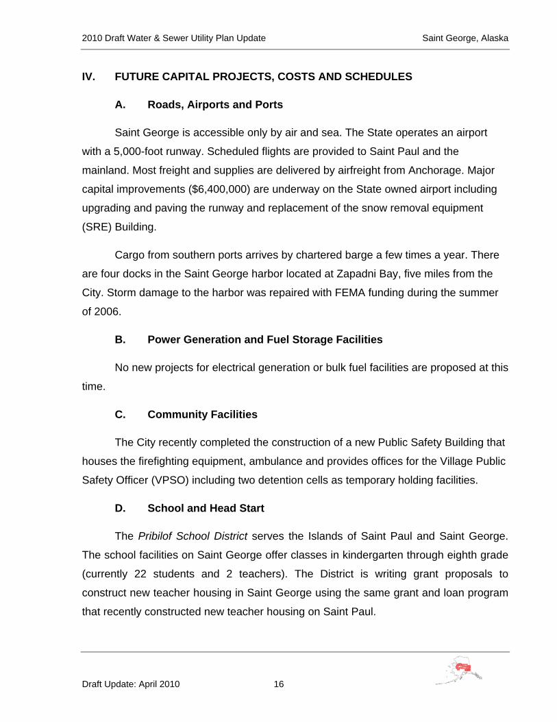
IV. FUTURE CAPITAL PROJECTS, COSTS AND SCHEDULES
A. Roads, Airports and Ports
Saint George is accessible only by air and sea. The State operates an airport
with a 5,000-foot runway. Scheduled flights are provided to Saint Paul and the
mainland. Most freight and supplies are delivered by airfreight from Anchorage. Major
capital improvements ($6,400,000) are underway on the State owned airport including
upgrading and paving the runway and replacement of the snow removal equipment
(SRE) Building.
Cargo from southern ports arrives by chartered barge a few times a year. There
are four docks in the Saint George harbor located at Zapadni Bay, five miles from the
City. Storm damage to the harbor was repaired with FEMA funding during the summer
of 2006.
B. Power Generation and Fuel Storage Facilities
No new projects for electrical generation or bulk fuel facilities are proposed at this
time.
C. Community Facilities
The City recently completed the construction of a new Public Safety Building that
houses the firefighting equipment, ambulance and provides offices for the Village Public
Safety Officer (VPSO) including two detention cells as temporary holding facilities.
D. School and Head Start
The Pribilof School District serves the Islands of Saint Paul and Saint George.
The school facilities on Saint George offer classes in kindergarten through eighth grade
(currently 22 students and 2 teachers). The District is writing grant proposals to
construct new teacher housing in Saint George using the same grant and loan program
that recently constructed new teacher housing on Saint Paul.

2010 Draft Water & Sewer Utility Plan Update Saint George, Alaska
Draft Update: April 2010 17
E. Health Clinic
TABLE 8—Community Medical Facilities Clinic/Hospital Saint George Clinic Operator Aleutian Pribilof Islands Association (APIA) Owner Village Council Alternate Health Care Saint George EMS/First Responders Health Comments The clinic is a qualified Emergency Care Center.
Saint George is classified as an isolated town/Sub-Regional Center, it is found in EMS Region 2H in the Aleutian/Pribilof Region. Emergency Services have coastal and air access. Emergency service is provided by volunteers.
(Alaska Department of Community and Economic Development)
F. Commercial Facilities
Crab, pollack and halibut fisheries use the Saint George harbor at Zapadni Bay
for temporary dockage during the fishing season. Continuing economic development
efforts have a goal of establishing permanent processing facilities on Saint George. The
Aleutian Pribilof Island Community Development Association (APICDA) plans to reopen
the halibut fish processing facility at the Zapadni Bay Harbor. APICDA also is in the
preliminary planning stages to construct a lodge for tourist visits.

2010 Draft Water & Sewer Utility Plan Update Saint George, Alaska
Draft Update: April 2010 18
V. EXISTING WATER & SEWER FACILITIES AND PLANNING CONDITIONS
A. Project Planning Area Map
Figure 1 is an overall map of Saint George Island delineating the location of the
City, the landfill and Zapadni Harbor.
B. History of Sanitation Improvements
The Pribilof Island City of Saint George (pop. 152, 2000 Census) has had piped
water and sewer for over 60 years. The federal government (National Marine Fisheries)
installed a then state-of-the-art collection and distribution systems in the 1940’s and
1950’s. The government essentially built and operated a “company town” on Saint
George to run its fur sealing enterprise. Sealing was halted in 1983 and the government
pulled out, transferring the aged water and sewer infrastructure to the newly created
City of Saint George. As-built records are sketchy. Institutional memory was lost.
Concerns about the integrity of the water distribution and sewage collection
systems, and about fire protection for several multi-million dollar structures prompted
the City of Saint George to request funds from the State of Alaska Village Safe Water
Program to locate, map and evaluate the water distribution and wastewater collection
systems. The City performed the work with assistance from CE2 Engineers, Inc. (CE2).
Notice to proceed with the work was given to CE2 on May 15, 2001. Shortly thereafter
an Aquatech trailer-mounted sewer jet was purchased in order to clean the sewer lines
prior to assessing their condition. In late May, City workers uncovered valves, manholes
and cleanouts. Manholes were cleaned and inspected. CE2 surveyors made a map of
the sewer system. Manhole inspections continued into June. The sewer cleaning
equipment arrived on June 26. Cleaning of the sewer lines was postponed for a month
due to the shortage of City workers. Sewer line cleaning and inspection began on July
25 and continued through August.

2010 Draft Water & Sewer Utility Plan Update Saint George, Alaska
Draft Update: April 2010 19
Figure 1 Overall Map
2010 Draft Water & Sewer Utility Plan Update Saint George, Alaska
Draft Update: April 2010 20
Exploratory digs were performed in August to locate water valves. House
plumbing inspections began in August and were completed on September 3, 2001.
Field data was summarized onto spreadsheets and placed on an aerial photo base map
in mid-September, followed by the analysis and report.
This system evaluation included a field-verified overall map of both the
distribution and collection systems, to the extent that those maps could be produced
from as-built drawings, construction drawings, recollections of residents and a limited
number of excavations, An assessment of the condition of the existing water distribution
and wastewater collection systems – components of which range in age from just a few
years to over 60 years and a prioritized list of recommended improvements to both the
water distribution and wastewater collection systems. Capital and O&M costs were
included for the recommended improvements. A brief review produced a list of
deficiencies of plumbing within the homes.
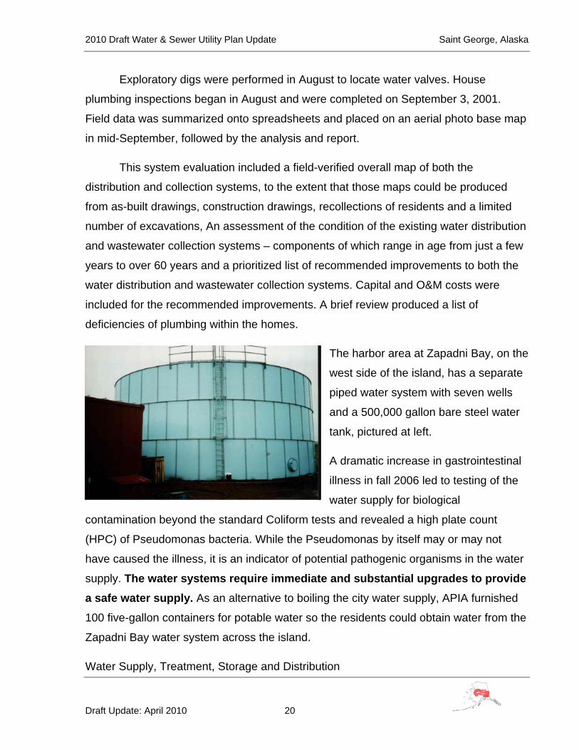
The harbor area at Zapadni Bay, on the
west side of the island, has a separate
piped water system with seven wells
and a 500,000 gallon bare steel water
tank, pictured at left.
A dramatic increase in gastrointestinal
illness in fall 2006 led to testing of the
water supply for biological
contamination beyond the standard Coliform tests and revealed a high plate count
(HPC) of Pseudomonas bacteria. While the Pseudomonas by itself may or may not
have caused the illness, it is an indicator of potential pathogenic organisms in the water
supply. The water systems require immediate and substantial upgrades to provide a safe water supply. As an alternative to boiling the city water supply, APIA furnished
100 five-gallon containers for potable water so the residents could obtain water from the
Zapadni Bay water system across the island.
Water Supply, Treatment, Storage and Distribution
2010 Draft Water & Sewer Utility Plan Update Saint George, Alaska
Draft Update: April 2010 21
Four wells provide water for the City:
TABLE 9—Active City Water Wells Well
Number Date
Completed Depth From Top of Casing (feet) Initial Test Pumping Drillers Comments
7 Jul-87 240 12 gpm/72 hrs, 4 ft drawdown Water in last few feet
8 Aug-87 240 12 gpm/4 hrs, 3 ft drawdown
Water bearing last 7 feet
9 Aug-88 240 6 gpm/4 hrs, 0.1 ft drawdown CL- at 75ppm
10 Aug-88 243.5 6 gpm/7.6 hrs , 0.75 ft drawdown CL- at 150 ppm
The well pumps are valved to limit volume to 5
gallons per minute (gpm) per well, for a total
capacity of 20 gpm. The electrical controls for the
wells are located in a 20-foot connex near Well 7;
an emergency generator was initially installed, but
has been removed. The wells do not have level
controls and have pumped dry on occasion,
causing the pumps to overheat and fail. The wells
pump through a common header to a small
building (12’ x 12’) and then discharge to the 286,000-gallon water storage tank. The
small building was initially a metering and chlorination point, however no chlorine
injection equipment exists at this time.
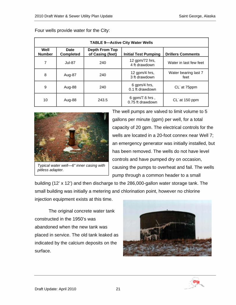
The original concrete water tank
constructed in the 1950’s was
abandoned when the new tank was
placed in service. The old tank leaked as
indicated by the calcium deposits on the
surface.
Typical water well—6” inner casing with pitless adapter.

2010 Draft Water & Sewer Utility Plan Update Saint George, Alaska
Draft Update: April 2010 22
The current 286,000-gallon water tank is
bare steel and has been susceptible to
freezing, especially when some of the well
pumps are out of service and the tank
contains only a few feet of water.
Sixty residences (43 occupied full time, 15
seasonal and 2 vacant) are connected to
the system and are plumbed. The water mains installed in the 1950’s were cast iron,
and water service lines were flared soft copper. Some time prior to 1985 cast iron water
mains on the east side of town were replaced with 6” PVC mains.
In 1990-91 a contractor to the State of Alaska Village Safe Water Program
replaced some waterlines with new 6” ductile iron (DIP) mains and 1” copper services.
Unfortunately these “improvements” created a branching, dead-ended 6” system that
has little fire fighting capability and causes potable water to stagnate in dead end lines.
In 1999 the City used VSW funds to construct a new 286,000-gallon water
storage tank. 8” ductile iron pipe was installed to connect the tank to the existing 6”
main that supplies the town. This 80 lineal foot (LF) line is believed to be the only line
larger than 6” in the entire distribution system. In 2001 the City constructed 200 linear
feet of 6” water main to serve a 6-plex in the southwest corner of town.
Figure 2, on the next page, shows the existing water distribution system. The
system “floats” on the 286,000-gallon ground level water storage tank located on the hill
southeast of town. The water distribution system can generally be described as a three-
branch system. Mains are nearly all 6” except for an 80 ft segment of 8” ductile iron pipe
that connects the water tank to the 6” feeder main in Cemetery Road. Some mains and
services to high value properties on Waterfront Street are 2” galvanized iron pipe.

2010 Draft Water & Sewer Utility Plan Update Saint George, Alaska
Draft Update: April 2010 23
Figure 2 Existing Water Distribution System
Update and reduce to 11 x 17 map one in original report
2010 Draft Water & Sewer Utility Plan Update Saint George, Alaska
Draft Update: April 2010 24
Three 6” branch lines serve three areas of town. Choochkie Heights Subdivision
on the south side of town is served by a 6” ductile main which branches off the main
supply line at the intersection of Choochkie Heights Road and Cemetery Road. This
branch generally heads west and dead-ends at the 6-Plex on Gavaruski Avenue.
Past Choochkie Subdivision, the 6” main supply line continues north to the
northeast corner of the ball field, then tees east and west. The easterly 6” PVC branch
cuts behind the houses in Tract 52 in the southeast corner of town, then heads
northwesterly through the school property to enter the Advance Avenue right-of-way
near the power plant. This main continues as 2” galvanized iron pipe in the Avenue to
Waterfront Street, where it ends. Approximately 200 ft south of the school, a 6” DIP tees
to the west to serve seven homes on an unnamed street. This main dead-ends on the
east side of the Community Center.
Another 6” ductile iron branch serves the west side of town. This waterline
branches off the main supply line south of the Community Center and heads west,
serving three houses on the north side of Community Street. The branch line then turns
90º and heads north through side lots and across roadways to the south side of the
church. This 450 LF segment of north / south main is believed to be 6” cast iron pipe
dating to the 1940’s. The branch line continues as 6” DIP along the east side of the
church north to Waterfront Street where it serves the City Complex and the restored
seal plant. Several minor 6” lines branch east and west off the main north/south branch
to serve three blocks of housing, and two commercial buildings north of Sunset
Boulevard. All of these dead end sub-branches are also 6” DIP. Most are located
outside of platted road rights-of-way, generally along back lot lines.
The distribution system contains the following elements:
Watermain (4” or larger):
• 80 LF of 8” DIP
• 4,265 LF of 6” DIP
2010 Draft Water & Sewer Utility Plan Update Saint George, Alaska
Draft Update: April 2010 25
• 1,750 LF of 6” PVC
• 450 LF of 6” cast iron
• 140 LF of 4” DIP
• Main line valves – 14 ea. (All in working order)
• Fire hydrants – 18 ea. (Salt air corrosion is noticeable and most caps are “frozen”
from corrosion)
• Services – 72 (2001 count) (Mostly ¾” and 1” soft copper. A few are 1” and 2”
galvanized iron pipe.)
Wastewater Collection, Treatment and Disposal
Original sewer service lines were cast iron, and sewer mains were vitrified clay
pipe. Sometime prior to 1985, a few segments of the clay pipe sewer system were
replaced with asbestos cement (transite) pipe. In 1985-86 the Public Health Service
(PHS) installed four community septic tanks, replaced a few clay sewer mains with
ductile iron mains and extended water and sewer lines to a new housing subdivision on
the south side of town.
Figure 3, on the next page, shows the existing wastewater collection treatment
and disposal system. All wastewater is conveyed by gravity flow. Sewer mains are
generally buried four to eight feet deep. The community is divided into two wastewater
drainage basins. The south and west sides of town flow to an 8” DIP trunk line that
skirts the westerly edge of the community, conveying wastewater from approximately 34
housing units and commercial establishments to septic tanks located on Lot 4, Tract 43
near the intersection of Sunset Boulevard and Waterfront Street. The west side
treatment works consists of two 5,000-gallon septic tanks in series. Effluent from the
septic tanks flows through an 8” DIP line north, between the seal plant and the electrical
and plumbing shop (E&P shop), to the beach, then east along the beach to the outfall
manhole.

2010 Draft Water & Sewer Utility Plan Update Saint George, Alaska
Draft Update: April 2010 26
Figure 3 Existing Wastewater Collection system
Update Map 3 from original report and reduce to 11 x 17.
2010 Draft Water & Sewer Utility Plan Update Saint George, Alaska
Draft Update: April 2010 27
The west side collection system contains the following elements:
• 3,670 LF of 8” sewer main including:
• 3,320 LF 8” DIP
• 350 LF 8” asbestos cement (AC) pipe
• 340 LF of 6” sewer main including:
• 190 LF vitrified clay pipe
• 150 LF ductile iron pipe
• 350 LF of 4” concrete sewer main
• 21 pre-cast concrete manholes
• 1 cleanout found, more suspected
• 34 each, 4” cast iron services
The east side of town drains to a second pair of 5,000 gallon septic tanks in
series located on the beach northwest of the carpenter shop and east of the previously
described outfall manhole. Wastewater from the east side of town is conveyed to the
septic tanks through a combination six-inch and eight-inch interceptor that trends east
along the beach behind the carpenter shop, then heads south through the school yard
to Tract 52 at the southeasterly edge of the development. Six-inch vitrified clay collector
mains branch east and west from the interceptor to serve clusters of homes around the
Community Center. Approximately 35 homes, the school, Community Center and City
complex are served by the east side collection system.
2010 Draft Water & Sewer Utility Plan Update Saint George, Alaska
Draft Update: April 2010 28
The east side system contains the following elements:
• 180 LF of 8” asbestos cement (AC) main
• 2,720 LF of 6” sewer main including:
• 2,030 LF of vitrified clay pipe
• 690 LF of DIP
• 40 LF of 4” cast iron sewer main
• 5 brick manholes
• 7 precast concrete manholes
• 34 each, 4” cast iron services
Effluent from the east side septic tanks flows west along the beach to the
common outfall manhole then out to sea through a six-inch ductile iron outfall.
Solid Waste Collection and Disposal
The first phase of construction of a Class III landfill for the City of Saint George
was completed and began receiving waste in fall 2005. It is located about three miles
southwest of the City of Saint George, south of Zapadni Bay Road (see Figure 1). A
“burn box” is used to reduce the volume of wastes and Petroleum Contaminated Soils
(PCS) have been stockpiled at the landfill to be used for cover material.
The first phase of landfill construction was funded by the National Oceanic and
Atmospheric Administration (NOAA) and administered by the Village Safe Water (VSW)
program. The City currently operates a mandatory solid waste collection service for all
residents. Collection personnel must enter each residence and commercial
establishment to collect the waste as a preventative measure against foxes ripping open
bags or opening containers left outside. The City does not have a compactor style
garbage truck; therefore, collection is accomplished using a dump truck. By ordinance,

2010 Draft Water & Sewer Utility Plan Update Saint George, Alaska
Draft Update: April 2010 29
residents are not allowed to haul their own wastes to the landfill. Collection occurs twice
per week, although residents can subscribe to once per week pickup at a reduced fee.
NOAA is nearing completion of a federally funded petroleum contaminated soil
(PCS) clean up and removal of Light Non-Aqueous Phase Liquids (LNAPLs) floating on
the ground water surface.
C. Condition of Facilities
Water Supply, Treatment, Storage and Distribution
The water supply is obtained from a “thin” layer of fresh water that “floats” on the
brackish water table. See Appendix B for the well logs and Appendix C for the U. S.
Geological Survey Reconnaissance of the Water Resources of Saint George Island
(1976). The limited fresh water supply requires the water system to conserve as much
water as practicable.
At the time of this report the water is not treated. A chlorination and metering
point was built in a small building near the water tank where the four wells discharge
through a common header. The chlorination equipment is in disrepair and not functional
at the present time.
The City water supply is piped to a 286,000 gallon un-insulated bolted steel water
tank located on a hill to the south of the City. The elevation of the tank provides the
operating pressure for the distribution system. The tank is not insulated and not
circulated which subjects it to freeze up during the winter months. It completely froze in the winter of 2005-2006 when problems with the well pumps reduced the available
volume in the tank. APIA provided 100 five-gallon potable water containers for local
residents to travel to the Zapadni Bay water system to obtain their drinking water.
The existing water distribution system evolved from a cast iron system that was
built in the 1940’s and 1950’s. Understanding of the present day system suffers from
lack of reliable as-built information for all subsequent construction. No one with the City
remembers how or when PVC replaced the cast iron pipe on the east side of town.
2010 Draft Water & Sewer Utility Plan Update Saint George, Alaska
Draft Update: April 2010 30
What is known is that the Public Health Service (PHS) designed and built the system for
the south side housing area (Choochkie Heights Subdivision) in the mid-1980’s and that
the State of Alaska Village Safe Water Program (VSW) replaced the feeder main in
Cemetery Road and most of the sub-branches on the west side of town in the 1990’s.
Lack of long term planning (and possibly funding) built a system that is
functionally inadequate by today’s standards. While the system is reasonably tight (few
leaks), there are glaring deficiencies in both the layout and function of the system,
including the following:
The system is branched rather than networked or “looped”, meaning that
stagnant water resides in dead end pipes.
The fire flow delivery rate is less in the existing branched system than in a similar
looped system, because water has only one pathway to each hydrant. Fire flows are
further restricted by the 1991 decision to install a 6” feeder main, rather than an 8” or
larger main, in Cemetery Road, from the vicinity of the water tank to the branch line
intersection points near the Community Center. For example, the volume now available
on Waterfront Street is reduced from the preferred 1,000+ gallons per minute (gpm) to
about 700 gpm.
The distribution system lacks hydrants in the vicinity of high value properties.
Additional valves were also needed to limit customer inconvenience during leak repair.
(Note: a dozen valve boxes found among the left over material may indicate that some
valves were buried without boxes during initial construction.)
The VSW work of 1990-91 apparently left a 450 lineal foot (LF) length of then
over 40-year-old, 6” cast iron pipe in the backbone of the west side branch. This main,
which cuts through side lots and crosses traveled ways between Community Street on
the south and Government Street on the north, connects two segments of 6” main that
were replaced in 1991. The remaining cast iron is presumed to be in as bad of shape as
the adjacent lines that were replaced. It is conjectured that those directing the 1990-91

2010 Draft Water & Sewer Utility Plan Update Saint George, Alaska
Draft Update: April 2010 31
works thought it was either too difficult or too expensive to work in side lots, or reroute
mains, and therefore chose to leave the over 40-year-old 6” cast iron main in service.
Finally the 1990-91 work apparently installed mains on private property without
easements. The City occasionally has trouble appeasing property owners whose yards
are disrupted when repairs are made and/or hydrants are flushed. (Site Control will be
obtained for all replacement lines that are not in the rights-of-way).
The water distribution system is marginally functional, not meeting design
standards for mainline pipe diameter and circuiting of the distribution mains. Because
the City has a very limited water supply – four flow-restricted wells that skim a combined
total of 20 gpm off the top of a brackish water table, the City is extremely vulnerable to
leaks in the distribution system. The existing distribution system offers little comfort to
utility and fire department personnel.
Wastewater Collection, Treatment and Disposal
During the summer of 2001 all mains and manholes within the Saint George
wastewater collection system were cleaned and inspected. Summaries of the inspection
reports appear in Tables 10 and 11. The location of each manhole can be determined
by referring to Figure Three (3). The collection system is comprised of gravity sewers
made of three different piping materials: ductile iron pipe, all of which was installed by
the Public Heath Service in the mid-1980’s; vitrified clay pipe, all of which was installed
prior to 1951 by National Marine Fisheries; and a few segments of asbestos cement
pipe, in both the east and west drainage basins, the vintage and origin of which are
unknown. The ductile iron pipe has fared well except for 525 ft (three segments) of 8-
inch main on the easterly side of Choochkie Heights Road, which appears to have
settled. The most southern of the three segments, between manholes 1B and 1C, was
surveyed at a grade of 0.26%, just over half of the minimum required grade for an 8-
inch gravity sewer. This 525-foot reach needs to be re-graded, or cleaned on a regular
basis, to prevent blockages from forming. The rest of the ductile iron system, including
the manholes, appears to be intact.

2010 Draft Water & Sewer Utility Plan Update Saint George, Alaska
Draft Update: April 2010 32
The same cannot be said of the asbestos cement pipe, which is also called
“transite”, and of the vitrified clay pipe. These reaches of the collection systems are
fraught with problems ranging from collapsed and severed pipe to lengths of sewer
main that are sagged, bowed or corkscrewed. Five manholes on the clay system are constructed of brick. All have failed and need replacement. The vitrified clay and
asbestos cement segments of the system (pipe and manholes) have reached the end of
their useful lives and should be replaced with 8-inch ductile iron pipe and precast
manholes.
Note also that many reaches of the vitrified clay and asbestos cement systems
are installed on private property without easements. This situation is unacceptable to
homeowners and must be corrected with the new construction.
TABLE 10 – SEWER MAIN CONDITION SUMMARY REPORT
REACH OF SEWER MATERIAL TYPE & SIZE
LENGTH CONDITION
FROM TO
EAST DRAINAGE 4A 4B 6” Clay 314.7 LF No moon in this section. Line collapsed. 4B 3D 6” Clay 217.4 LF Vertical alignment deviation (1/4 moon). 3A 3C 6” Clay 205.9 LF Horizontal and vertical deviation (no
moon). 3B 3C 6” Clay 152.9 LF Line curves out of sight (no moon). 3C 3D 8” Clay 223.4 LF No light through pipe (no moon). 3D 3E 8” Clay 156.1 LF Vertical deviation (no moon). 3E 3F 8” A.C. 105.9 LF Horizontal and vertical deviation (1/2
moon). 3F 3G 6” A.C. 108.5 LF No moon in this section. 3G 3H 6” DIP 113.1 LF Good 3H 3I 6” DIP 107.3 LF Good 3I 3J 6” DIP 209.0 LF Good 3J Tanks 6” DIP
194.7 LF Good
Tanks 3K 6” DIP Good 3K Outfall 6” DIP Good
WEST DRAINAGE C.O. 1A 8” DIP 210.0 LF Good 1A 1B 8” DIP 80.2 LF Horizontal alignment deviation (7/8
moon). 1B 1C 8” DIP 230.5 LF Horizontal and vertical alignment
deviation (1/2 moon).

2010 Draft Water & Sewer Utility Plan Update Saint George, Alaska
Draft Update: April 2010 33
TABLE 10 – SEWER MAIN CONDITION SUMMARY REPORT
REACH OF SEWER MATERIAL TYPE & SIZE
LENGTH CONDITION
FROM TO
1D 1C 8” DIP 181.2 LF Good 1C 2A 8” DIP 174.8 LF Good 2A 2B 8” DIP 210.1 LF Good 2B 2C 8” DIP 222.9 LF Good
2B-1 2B 8” DIP 134.7 LF Good 2C 2D 8” DIP 180.0 LF Horizontal & vertical deviation (1/2 moon). 2D 2E 8” DIP 271.5 LF Good 2E F2 8” DIP 124.9 LF Good F2 G2 8” DIP 148.8 LF Good G2 Z 8” DIP 87.4 LF Good Z AI 8” A.C. 331.8 LF Horizontal and vertical deviation (no
moon) G2 H2 8” DIP 78.7 LF Horizontal deviation (7/8 moon) H2 I2 8” DIP 260.3 LF Horizontal deviation (3/4 moon) I2 J2 8” DIP 170.1 LF Vertical deviation (3/4 moon) J2 Tanks 8” DIP 13.0 LF Good
Tanks K2 8” DIP 90.1 LF Horizontal and vertical deviation (no moon)
K2 L2 8” DIP 141.7 LF Horizontal and vertical deviation (no moon)
L2 3K 8” DIP 148.8 LF Good

2010 Draft Water & Sewer Utility Plan Update Saint George, Alaska
Draft Update: April 2010 34
TABLE 11 – SAINT GEORGE MANHOLE CONDITION SUMMARY REPORT

2010 Draft Water & Sewer Utility Plan Update Saint George, Alaska
Draft Update: April 2010 35
House Plumbing
A cursory inspection of the plumbing within many of the homes in the village was
performed during August and early September 2001. Except for the homes within
Choochkie Heights Subdivision, the majority of the homes are at least 50 years old. The
deficiencies noted at each home appear in the following table. A house number index
sheet follows the table.
TABLE 12 – House Plumbing Condition Summary Report (2001)
HOUSE NO. DEFICIENCIES NOTED OCCUPANT COMPLAINTS 01 • None 02 • P-trap leaks under the kitchen sink Pipes sweat 03 • None 04 • None 05 • None 06 • None 110 • None 111 • None 112 • Lavatory chipped and rusted 113 • Cracked bathtub
• Water damage and rotted flooring below the lavatory
114 • None 115 • None 116 • Toilet leaks at the wax ring
• Water key box is bent and won’t accept a valve key
1 • Mold behind the tub enclosure 2 • None 3 • Not occupied 4 • Corroded cast iron drain pipes, P-trap leaks under
the sink • Bathtub chipped • Sinks chipped
5 • Not occupied 6 • Not occupied 7 • None Owner says the sewer service line has a
flat grade 8 • Not inspected 9 • None

2010 Draft Water & Sewer Utility Plan Update Saint George, Alaska
Draft Update: April 2010 36
TABLE 12 – House Plumbing Condition Summary Report (2001)
HOUSE NO. DEFICIENCIES NOTED OCCUPANT COMPLAINTS 10 • None 11 • Toilet cracked • Tub and toilet drain slowly 12 • Water pipes were broken in the basement. Walls
are damaged from flooding. • No vent • Bathtub and sinks chipped • Drain pipes missing
• Nothing works
13 • Couldn’t find a vent • Tub bottom rusted where enamel is missing
Very low water pressure
14 • Lavatory not hooked up • P-trap leaks beneath kitchen sink • Water pipes show signs of corrosion
15 • None 16 • None 17 • None 18 • Lavatory rusted
• Bathtub rusted • Hot and cold water pipes to the bathtub have been
removed along with the tub valves • 4” cast iron waste line leaks in the basement
19 • Lavatory not plumbed • Vents plugged
Washer often won’t drain properly
20 • Drain valve and linkage missing from the bathtub 21 • Lavatory disconnected because of water leaks
• Bathtub is rusted
22 • None 23 • None 25 • Not inspected
26 • 4” sewer service backs up / won’t drain Sewer doesn’t work 27 • Not inspected 28 • Not inspected 29 • Not inspected 30 • Not inspected 31 • Sub-slab cast iron drain pipes are prone to
blockage Drain lines beneath the basement floor back up about once a month
32 • Not vented • Bathtub, lavatory and kitchen sink are rusting out • Bathroom floor is warped
“Sewer gas” odor in the house, especially when winds are strong

2010 Draft Water & Sewer Utility Plan Update Saint George, Alaska
Draft Update: April 2010 37
TABLE 12 – House Plumbing Condition Summary Report (2001)
HOUSE NO. DEFICIENCIES NOTED OCCUPANT COMPLAINTS 33 • None 34 • Not inspected 35 • Not inspected 36 • Not inspected 37 • Not vented outside of house 38 • P-trap beneath kitchen sink leaks
• Lavatory not plumbed because of broken drain lines
• Toilet cracked and leaks, bathtub is cracked and slow to drain
39 • Slow drains 40 • Not inspected 41 • None 42 • Corroded water pipes
• Drain line missing from lavatory • Tub rusted • Toilet leaks at wax ring
43 • Not inspected 44 • Not inspected
Cottage A • Not occupied Cottage C • Downstairs lavatory faucet leaks Cottage D • Not inspected
In general, the plumbing is in reasonable condition given the age of the homes.
However, the existing toilets are large users of water and should be replaced with
“water saver” fixtures. This will substantially reduce the amount of water consumed.

2010 Draft Water & Sewer Utility Plan Update Saint George, Alaska
Draft Update: April 2010 38
HOUSE PLUMBING KEY MAP

2010 Draft Water & Sewer Utility Plan Update Saint George, Alaska
Draft Update: April 2010 39
D. Financial Status of Operating Facilities
The Business Plan (attached as Appendix I) shows that there will be adequate
revenues to fund the ongoing O&M and R&R costs after the proposed improvements
are in place.
Current emergency repairs to the failing distribution and collection system, failure
of the well pumps due to the lack of level controls and inadequate volume of water to
keep the water tank from freezing consume a large portion of the available revenue and
at times electric utility revenue must be diverted to compensate for the required repair
expenditures.

2010 Draft Water & Sewer Utility Plan Update Saint George, Alaska
Draft Update: April 2010 40
VI. LAND STATUS
A. Land Owners in Proposed Project Area
1. Federal
The National Oceanic and Atmospheric Administration (NOAA), a division
of the United States Department of Commerce has transferred ownership of
properties that were part of the U.S. Government sealing operations until 1983 to
the tribal government.
2. State
The State of Alaska, Department of Transportation and Public Facilities
owns the active airport on the Island of Saint George. The airport is located near
Zapadni Bay and does not impact the project improvements proposed in this
Plan Update.
3. Regional Land Corporation
The Aleut Corporation is the regional corporation that controls most of the
subsurface rights on Saint George Island. The improvements proposed by this
plan update are not expected to require obtaining additional subsurface rights.
4. Village Land Corporation
TABLE 13--ANCSA Land Entitlement (Alaska Department of Community and Economic Development)
Village Corporation Saint George Tanaq Corporation
12(a) Land Entitlement* 115,200 acres
12(b) Land Entitlement** 13,446 acres
14(c)(3) Land Status
14(c)(3) Status*** Completed
14(c)(3) Comments Additional 14(c)(3) in 1990
14(c)(3) Agreement Signed No
14(c)(3) Acres 436.0
Map of Boundaries done Yes

2010 Draft Water & Sewer Utility Plan Update Saint George, Alaska
Draft Update: April 2010 41
TABLE 13--ANCSA Land Entitlement (Alaska Department of Community and Economic Development)
Date Plat Filed 01/29/1985
Plat Number BLM Records
Recording District Aleutian Islands Recording District
Municipal Land Trust No
* ANCSA 12(a) land entitlement to village corp. from federal government
** ANCSA 12(b) land reallocated to village corp. from Reg. Native Corp.
*** Under ANCSA 14(c)(3), villages must reconvey surface estates to the local city government to provide for community use and expansion
5. City or Tribal
The City of Saint George holds title to all of the rights-of-way in the
developed area of the city where the majority of improvements to the piping
systems will occur. The Tribal Government is the owner of record of a number of
parcels transferred from the National Marine Fisheries (NMF) when the sealing
operations ceased in 1983.
6. Native Allotments
The majority of privately held parcels were transferred by patent from the
Bureau of Land Management (BLM) to the Saint George Tanaq Corporation and
subsequently by Quit Claim Deed to the individual property owners. There are no
known Native Allotments in the area where improvements to the water and sewer
system are proposed.
7. Homesteads
There are no known homesteads in the area of the City of Saint George
where the proposed improvements will be built.
8. Other Owners
No other owners are expected to be impacted by the proposed
improvements at this time.

2010 Draft Water & Sewer Utility Plan Update Saint George, Alaska
Draft Update: April 2010 42
9. Existing Easements
Many reaches of the vitrified clay and asbestos cement wastewater
collection piping are installed on private property without easements. This
situation is unacceptable to homeowners. Site control will be obtained for the
placement of any new piping on private property.
B. Traditional Use Areas
Traditional use areas are not located in the city proper where improvements to
the water and sewer systems are proposed. The proposed new wells may be located in
berry picking areas but construction disturbance will be minimal.
C. Land Conflicts that Could Affect the Project, Platting Status
The only known land conflict affecting the proposed projects is the location of
existing water and sewer mains on properties that are not owned by the city or for which
easements were not obtained to place the mains.
D. Proposed Solutions to Land Conflicts
Where new mains are to be installed on property not owned by the city,
easements will be obtained. If easements cannot be obtained without objection from
private property owners, the project may be required to reroute some of the proposed
maims to overcome this conflict.

2010 Draft Water & Sewer Utility Plan Update Saint George, Alaska
Draft Update: April 2010 43
VII. NEED FOR PROJECT
A. Health and Safety Concerns
The lack of a trusted and reliable water supply for any community causes a
marked deterioration in the quality of life. This past year the City of Saint George
identified a level of bacterial contamination of the water supply that does not occur
frequently in Alaskan water systems. Assessing and treating such an occurrence in a
remote community such as Saint George is very difficult. Measures need to be in place
to prevent future outbreaks.
In addition, a leak in the water distribution system this January caused the water
storage tank to run totally dry. The lack of domestic water supply and fire protection
water is a health and safety concern of the greatest magnitude. The aging water
distribution system requires immediate attention.
B. Environmental Concerns
The City wastewater treatment and disposal is accomplished through septic
tanks and discharge of the liquid to an ocean outfall. The lack of a septage-pumping
vehicle has caused the septic tanks to fill with solids and discharge untreated sewage.
Discharge of untreated sewage is a serious environmental concern to all users of the
immediate beach area. A new septage pumping truck will allow the city to remove and
dispose of solids in an environmentally acceptable manner.
C. System Growth Capacity
The water and wastewater systems, once improved, have adequate capacity to
serve the projected 20-design population for the City of Saint George.

2010 Draft Water & Sewer Utility Plan Update Saint George, Alaska
Draft Update: April 2010 44
VIII. COMMUNITY CAPACITY
A. Management Status
An employee of the public works department who holds the appropriate operator
certifications performs day-to-day operation of the water and sewer systems on an as
needed basis. When a water or sewer task requires more than one person, additional
City employees from the public works department are assigned to assist the water /
wastewater operator. The public works department charges all water and sewer related
labor to the appropriate Utility.
The City finance director, a graduate accountant, supervises water and sewer
billing, collections, etc. Finance department time is charged to each utility for providing
these services.
B. Financial Status
The fiscal year 2005 Municipal Revenues and Expenditures reported on the
Alaska Division of Community Advocacy web site show the Water and Sewer Enterprise
Fund with $108,828 in revenue and $220,230 in expenditures. This negative imbalance
was offset by a positive imbalance in the Electric Utility. The majority of the deficit is
directly attributed to the need for emergency repairs. Overtime labor for breaks in the
water distribution system and blockages in the sewer piping are very costly.
The Business Plan cash flow shows that if the need for repairs are reduced to a
normal level, the water and sewer utility can operate at a slight positive cash balance
while funding a small annuity for future capital replacement costs. (See Appendix I for
the Business Plan).
C. System Operation & Maintenance (O&M) Status
The water and wastewater system operators work closely with the Remote
Maintenance Worker (RMW) from the Aleutian Pribilof Islands Association (APIA) to
keep the systems functioning. The need for capital improvements and the remote
location of Saint George makes this a frequent challenge.

2010 Draft Water & Sewer Utility Plan Update Saint George, Alaska
Draft Update: April 2010 45
The City is not on the "Significant Non-Complier" (SNC) list. All testing and
reporting required by Federal and State regulations are being provided. O&M
requirements would decrease if the capital improvements outlined in this plan update
are implemented.
A system wide open bore flushing of the storage and distribution system will
reduce the build-up of deposited organic and corrosion debris which provide an
environment for bacteria to grow. This will require digging up the dead end mains and
opening the ends to provide adequate flushing velocities. This level of effort may be
beyond the financial and technical resources of the available onsite maintenance staff.

2010 Draft Water & Sewer Utility Plan Update Saint George, Alaska
Draft Update: April 2010 46
IX. SANITATION FACILITY ALTERNATIVES
A. Description
It is required that the drinking water supply meet Environmental Protection
Agency (EPA) standards. The EPA is responsible for the National Primary Drinking Water Regulations, which are health-related standards that establish the Maximum
Contaminant Levels (MCLs). MCLs are the maximum permissible level of a contaminant
in water delivered to users of a public water system. MCLs are enforceable under the
Safe Drinking Water Act. The EPA has also set unenforceable Maximum Contaminant
Level Goals (MCLGs) at levels where no known or anticipated adverse effects on health
occur and that allow an adequate margin of safety. The enforceable MCL is set as close
to the MCLG as reasonable, taking into consideration the costs and treatment
techniques available to public water systems. National Secondary Drinking Water Standards are unenforceable federal guidelines regarding taste, odor, color, and
certain other aesthetic characteristics of water. The EPA recommends them to states as
reasonable goals, but federal law does not require water systems to comply with them.
Regarding the bacteriological purity of drinking water the EPA regulations only
specify limits for coliform bacteria. The Heterotrophic Plate Count (HPC) test, also
called “total count” or “plate count”, provides an estimate of the total number of bacteria
in a sample that will develop into colonies during a period of incubation in a nutrient.
This test detects a broad group of bacteria including nonpathogens, pathogens, and
opportunistic pathogens, but it does not pretend to report all of the bacteria in the water
sample examined. HPC may be an indicator of poor general biological quality of
drinking water. A recommended MCL for human drinking water has not yet been
proposed, but the EPA does recognize the water quality deterioration implied by high
plate counts. The upper limit for potable water is usually 500 colony-forming units or
cfu/mL. The Handbook of Drinking Water Quality Standards and Controls, Van Nostrand
Reinhold, New York (1990) suggests water with counts under 100 cfu/mL should be
considered “potable” and values 100-500/mL “questionable”. Appendix E contains two
chapters from the World Health Organization on Heterotrophic Plate Counts and

2010 Draft Water & Sewer Utility Plan Update Saint George, Alaska
Draft Update: April 2010 47
Drinking Water Safety that discuss the amount and type of bacteriological contamination
that may be found in water supplies.
The Saint George water system has reported recent HPC’s of up to 200 cfu/mL
and Pseudomonas flourencenes has been speciated from those samples. These water
quality analyses are included in Appendix D. Based on the bacterial contamination
evident in recent samples, a rigorous program of open bore flushing must be
undertaken and continuous disinfection of the water supply should be undertaken,
although with a groundwater supply chlorination is not specifically directed by
regulation.
The age of much of the piping in the water distribution and wastewater collection
systems is beyond its expected service life. Lack of a “looped” water distribution
systems causes water to stagnate and reduces to firefighting capability of the
community.
Capital improvements to this aging system are needed. The alternative of “Do
Nothing” is not an option if the system is to continue to function.
B. Design Criteria
Table 14--Proposed Design Criteria Value Planning Period 20 years Design Population 200 Design Number of Service Connections (Customers) 72 Consumptive use is considered negligible. Water demand equals wastewater flow.
Average daily per capita usage (gpcd) 65 Total average daily usage (gpd) 13,000 Maximum daily per capita usage (gpcd) (1.5 peaking factor) 97.5 Total maximum daily usage (1.5 peaking factor) 19,500
Water Supply, Treatment, Storage and Distribution
The four active wells have a combined pumping capacity of 20 gallons per
minute or 28,800 gallons per day. The volume of water available from the existing wells
at 20 gpm would be adequate for the design period. However, many times the wells “run

2010 Draft Water & Sewer Utility Plan Update Saint George, Alaska
Draft Update: April 2010 48
dry” that is, the water level falls below the pumping level and the 5 gpm per well is not
available. Because there is only a “thin layer” of potable water, the pumps cannot be set
deeper. Two more wells should be drilled and connected so the amount of water
available remains at 20 gpm. The water supply is currently not treated. A disinfection
chemical (Sodium Hypochlorite) injection system is proposed to be added either for
continuous use or at a minimum in standby mode to treat the water supply if
contamination is suspected or identified.
The storage tank volume of 286,000 gallons is adequate for a 7-day supply plus
a 500-gallon per minute fire flow of 4 hours duration. The tank is uninsulated bolted
steel that leaves it susceptible to freeze up. Insulating the tank is recommended in this plan update. Additionally a mixing pump is also recommended to assist on
circulating water to prevent freezing and to mix the water when disinfection is being
provided. Water distribution improvements are discussed in detail under conceptual
layout below.
Wastewater Treatment and Disposal--Existing Septic Tanks
Figure 3 shows the location of two pairs of 5,000-gallon septic tanks. Each pair is
piped in a series configuration. One pair of tanks serves approximately 37 dwellings and
businesses on the west side of town. The other pair serves approximately 40 dwelling
units, the school and the city office complex on the east side of town.
The picture on the left
shows the four septic tank
risers at their location on
the beach.
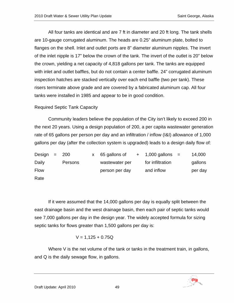
2010 Draft Water & Sewer Utility Plan Update Saint George, Alaska
Draft Update: April 2010 49
All four tanks are identical and are 7 ft in diameter and 20 ft long. The tank shells
are 10-gauge corrugated aluminum. The heads are 0.25” aluminum plate, bolted to
flanges on the shell. Inlet and outlet ports are 8” diameter aluminum nipples. The invert
of the inlet nipple is 17” below the crown of the tank. The invert of the outlet is 20” below
the crown, yielding a net capacity of 4,818 gallons per tank. The tanks are equipped
with inlet and outlet baffles, but do not contain a center baffle. 24” corrugated aluminum
inspection hatches are stacked vertically over each end baffle (two per tank). These
risers terminate above grade and are covered by a fabricated aluminum cap. All four
tanks were installed in 1985 and appear to be in good condition.
Required Septic Tank Capacity
Community leaders believe the population of the City isn’t likely to exceed 200 in
the next 20 years. Using a design population of 200, a per capita wastewater generation
rate of 65 gallons per person per day and an infiltration / inflow (I&I) allowance of 1,000
gallons per day (after the collection system is upgraded) leads to a design daily flow of:
Design
Daily
Flow
Rate
= 200
Persons
x 65 gallons of
wastewater per
person per day
+ 1,000 gallons
for infiltration
and inflow
= 14,000
gallons
per day
If it were assumed that the 14,000 gallons per day is equally split between the
east drainage basin and the west drainage basin, then each pair of septic tanks would
see 7,000 gallons per day in the design year. The widely accepted formula for sizing
septic tanks for flows greater than 1,500 gallons per day is:
V = 1,125 + 0.75Q
Where V is the net volume of the tank or tanks in the treatment train, in gallons,
and Q is the daily sewage flow, in gallons.

2010 Draft Water & Sewer Utility Plan Update Saint George, Alaska
Draft Update: April 2010 50
Using 7,000 gallons per day for “Q” in the above formula yields a net two-tank
required volume of 6,375 gallons. Each pair of existing tanks has a net volume of
approximately 9,636 gallons. This analysis shows that the volume of the existing septic
tanks is sufficient to accommodate the wastewater likely to be generated over the next
20 years under the stated assumptions – maximum population 200, 65 gallons of
wastewater per person per day, 1,000 gallons of infiltration and inflow per day and total
flow split equally between the east and west sides of town.
A field inspection conducted as part of this study revealed that the tanks are
badly clogged with solids. The solids need to be slurried and removed. Permission must
be sought from ADEC to dispose of the solids in a pit at the landfill. Lime must be
applied to the sludge to kill pathogens in accordance with ADEC sludge disposal
guidelines. The acquisition of a septage pumping truck as part of the proposed
improvements will allow the city to remove the solids and properly operate the existing
septic tanks.
Wastewater Outfall
Wastewater effluent from both pairs of septic tanks flows to a common outfall
manhole on the beach near the northeast corner of the seal plant, then through a 130 ft
long ductile iron outfall pipe to the Bering Sea. The elevation at the end of the outfall is
estimated to be -5 ft MLLW.
No NPDES permit was located for this discharge. The US Environmental
Protection Agency (EPA) regulates discharge of wastewaters to the marine
environment. The existing septic tanks meet EPA’s “primary treatment” requirements for
Alaskan villages discharging to salt water; however the outfall might have to be
extended to insure the proper dispersion of the treated effluent in the ocean.
The condition assessment and ocean current studies required to determine the
length and depth of the outfall are beyond the scope of this plan update and should be
included in a separate funding request for study monies to properly address the status
of the ocean outfall.

2010 Draft Water & Sewer Utility Plan Update Saint George, Alaska
Draft Update: April 2010 51
C. Conceptual Layout
Water Distribution System Improvements
The following improvements are necessary to optimize the performance of the
water distribution system. Refer to Figure 4 when reading the following descriptions.
The improvements are presented as prioritized. Note that because of the high economic
value of large structures in the lower third of the distribution system, all future mains
should be 8-inch diameter to accommodate fire flows.
With the well field supplying 20 gallons per minute, if the water tank cannot be
maintained at near capacity the required fire flow duration will not be met. An ocean
(salt) water pump and feed main could be installed in a location near the former sealery
to provide the volume of water required for fighting a large fire in the area of high value
properties. This would allow the fire department to “lay hose” from the salt water
“hydrant” to a fire in the high value area.
Waterfront Street Intertie (Priority 1)
Tie the east and west branches together by constructing an 8-inch main from the
hydrant near the power plant in Advance Avenue through Waterfront Street to the
hydrant at the intersection of Waterfront Street and Sunset Boulevard. Install at least
one new hydrant at the intersection of Advance Avenue and Waterfront Street. Replace
the existing galvanized iron service lines to the power plant, fish processing plant,
carpenter shop and seal processing plant. Install new water main (approximately 150
feet) with a fire hydrant to a point near the school for fire protection.
Replace 50+ Year Old Mains (Priority 2)
Abandon the 50+ year-old 6-inch cast iron line that runs north/south in the side
lots between Community Street and the southeast corner of the church. Replace this
main with a parallel main that ties to an existing 6-inch ductile iron pipe (DIP) main near
the southwest corner of Lot 25, Tract 52, follows the west line of Lot 25, the south line of
Lots 21 and 20, the south and east lines of lot 19, then traverses the east side of the
clinic on an easement, turns east in Zapadani Street to the Main Avenue intersection,

2010 Draft Water & Sewer Utility Plan Update Saint George, Alaska
Draft Update: April 2010 52
Figure 4

2010 Draft Water & Sewer Utility Plan Update Saint George, Alaska
Draft Update: April 2010 53
then heads north in Main Avenue past the west side of the hotel to Sunset Boulevard,
and finally northeast in Sunset Boulevard to tie-in with the Waterfront Street Intertie
improvements and the existing main that terminates in front of the garage, east of the
seal plant. This construction must also tie to existing mains in three places: on the north
side of Lot 19, Tract 52; near the intersection of Main Avenue and Government Street;
and at the end of the existing main northwest of the hotel. Spot excavation will be
required at three additional locations to disconnect the existing east / west sub-
branches from the cast iron main, remove the cast iron main and install connecting
pieces. Additional valves and hydrants should be installed as shown on Figure 4.
Replace Main Feeder from Water Tank (Priority 3)
The main feeder from the water tank to Community Street should be replaced
with a 10” feeder. The new feeder should tie to all three branches – the existing main in
Choochkie Heights Road, the east side branch just south of the Community Center and
the proposed Priority 2 improvements near the southwest corner of lot 25.
Choochkie Heights Subdivision–Ball Field Loop (Priority 4)
The south and west branches should be looped by a new 8-inch main that ties to
the 50 year old main replacements (Priority 2) improvements at the intersection on Main
Avenue and Sunset Boulevard, heads southwest past the post office and the store, then
turns south along the westerly property line of the ball field to tie-in to the dead end 6-
inch main by the 6-plex on Gavaruski Avenue.
These main extensions should tie into the existing 6-inch DIP main which dead
ends south of the store. A new service line should also be constructed for the store /
post office complex.
The above-recommended improvements will strengthen the water system by
looping the branches and replacing the most vulnerable system components, the 50+-
year-old cast iron main and the small diameter galvanized mains and services.
2010 Draft Water & Sewer Utility Plan Update Saint George, Alaska
Draft Update: April 2010 54
Wastewater Collection System Improvements
Figure 5, on the next page, shows a proposed layout for an improved sewer
system that builds upon the existing ductile iron system while replacing the vitrified clay
pipe and asbestos cement. Note that the new layout utilizes platted road corridors
wherever possible. When easements are required they parallel existing lot lines. Since
topographic mapping has not been completed for Saint George, this layout must be
confirmed by field survey as part of pre-design activities.
The proposed wastewater collection system improvements will require
installation of the following:
• 4,175 LF of 8” DIP sewer main
• 24 manholes
• 1 cleanout
• Approximately fifty (50) 4” cast iron sewer services from the main to the individual
structures

2010 Draft Water & Sewer Utility Plan Update Saint George, Alaska
Draft Update: April 2010 55
Figure 5 Goes Here
2010 Draft Water & Sewer Utility Plan Update Saint George, Alaska
Draft Update: April 2010 56
D. Unique Environmental Impacts
Extensive bacteriological contamination of the water system is a very serious
concern and a unique environmental impact. Treating this type of contamination is not a
normal function of a municipal water system.
E. Land Requirements and Easements
Some of the existing water distribution and sewer collection lines were
constructed on private property without recorded easements. These lines will be
rerouted to the public rights of way or easements will be obtained for any new piping
installed across private property.
F. Construction Constraints
Parts of the construction are likely to be difficult and costly due to tight quarters,
conflicting underground utilities, rock excavation and the need to keep the existing
systems in service while the new system is being constructed.
G. Impacts to Existing Infrastructure
1. Roads
Much of the piping recommended for replacement is located under
currently traveled ways. It will be necessary to coordinate the construction with
local residents to eliminate as much inconvenience as possible. The roads will be
restored to their original condition or better.
2. Electrical Power
A minimum amount of additional electric power will be required to operate
the proposed circulating pump to be placed in the water tank. Other proposed
improvements will not require additional electricity.

2010 Draft Water & Sewer Utility Plan Update Saint George, Alaska
Draft Update: April 2010 57
3. Bulk Fuel
No additional use of bulk fuel is anticipated.
H. Cost Estimates
1. Construction Cost Estimate
Summary of All Proposed Capital Construction Costs
Task Construction Segment Segment Cost
One Construct New Wells, Chlorinate Supply, Circulate Storage Tank & Well Pump (4) Level Controls $914,880
Two Waterfront Street Intertie $527,770Three Eliminate 50+ Year-Old Cast Iron Pipe $567,800Four Replace Main Feeder Line From Water Tank $523,500Five Choochkie Heights Subdivision–Ball Field Loop $595,480Six Insulate City Water Storage Tank $250,700
Seven Insulate Zapdni Bay Water Storage Tank $322,310Estimated Capital Cost Water System $3,702,440
Eight Sewer Collection & Disposal Improvements $2,744,720Estimated Capital Cost Wastewater System $2,744,720Estimated Total Capital Cost $6,447,160
*2009 dollars assuming force account construction / local wages
Water & Sewer Plan Update Preliminary Cost Estimate--Saint George, AlaskaTABLE 15--Study Level Cost Estimate*--Summary
*2010 adjusted for inflation
Water Supply, Storage and Distribution Capital Costs by Phases
The tables on the following pages, Table 16 through Table 22, show the
estimated costs for installing each of the water system improvements.

2010 Draft Water & Sewer Utility Plan Update Saint George, Alaska
Draft Update: April 2010 58
Item Activity Unit Unit Price Quantity Cost1 Mobilization LS $25,000 1 $25,000
2
Hydorgeologicial groundwater investigation, site and drill two new water wells to provide additional water supply
LS $345,000 1 $345,000
3 Install chlorine injection LS $40,250 1 $40,250
4
Add recurculation piping and pump to City water tank
LS $57,500 1 $57,500
5 Electrical Service to water tank circulating pump
EA $23,000 1 $23,000
6Install pumping level controls infour existing wells
LS $161,000 1 $161,000
7
Complete Work (As-Built Drawings, O&M Manuals, Startup, Operator Training, Warranty Work, Etc.) LS $30,000 1 $30,000
$681,750
$68,175
$749,900
$74,990$89,990$914,880
*2007 dollars assuming force account construction / local wages
Total Estimated Construction Cost
Contingency (10%)
Subtotal
2010 adjusted for inflation
Table 16--Study Level Cost Estimate*New Wells, Well Controls, Chlorination Equipment & Tank Recirculation
Engineering and Administration (10%)Construction Administration (12%)
Total Estimated Project Cost

2010 Draft Water & Sewer Utility Plan Update Saint George, Alaska
Draft Update: April 2010 59
Item Activity Unit Unit Price Quantity Cost1 Mobilization LS $149,500 1 $149,500
2Connect to existing watermain
EA $3,300 2 $6,600
3 8” water main LF $210 520 $109,200 4 8” gate valve EA $1,200 4 $4,800 5 Fire hydrant EA $5,900 5 $29,500 6 2 “service EA $9,100 3 $27,300 7 1” inch service EA $3,900 1 $3,900
8 School yard hydrant EA $32,500 1 $32,500
9
Complete Work (As-Built Drawings, O&M Manuals, Startup, Operator Training, Warranty Work, Etc.) LS $30,000 1 $30,000
$393,300$39,330
$432,600
$43,260$51,910$527,770
2010 adjusted for inflation
Study Level Cost Estimate*--Water Distribution SystemWaterfront Street Intertie (Priority One)
Engineering and Administration (10%)Construction Administration (12%)
Total Estimated Project Cost*2007 dollars assuming force account construction / local wages
Total Estimated Construction CostContingency (10%)
Subtotal
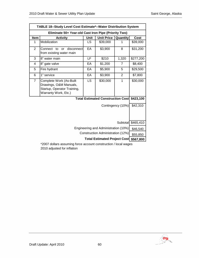
2010 Draft Water & Sewer Utility Plan Update Saint George, Alaska
Draft Update: April 2010 60
Item Activity Unit Unit Price Quantity Cost1 Mobilization LS $39,000 1 $39,000
2 Connect to or disconnectfrom existing water main
EA $3,900 8 $31,200
3 8” water main LF $210 1,320 $277,200 4 8” gate valve EA $1,200 7 $8,400
5 Fire hydrant EA $5,900 5 $29,500
6 1” service EA $3,900 2 $7,800
7 Complete Work (As-Built Drawings, O&M Manuals, Startup, Operator Training, Warranty Work, Etc.)
LS $30,000 1 $30,000
$423,100
$42,310
$465,410
$46,540
$55,850$567,800
*2007 dollars assuming force account construction / local wages
Total Estimated Construction Cost
Contingency (10%)
Subtotal
2010 adjusted for inflation
TABLE 18--Study Level Cost Estimate*--Water Distribution System
Eliminate 50+ Year-old Cast Iron Pipe (Priority Two)
Engineering and Administration (10%)Construction Administration (12%)
Total Estimated Project Cost
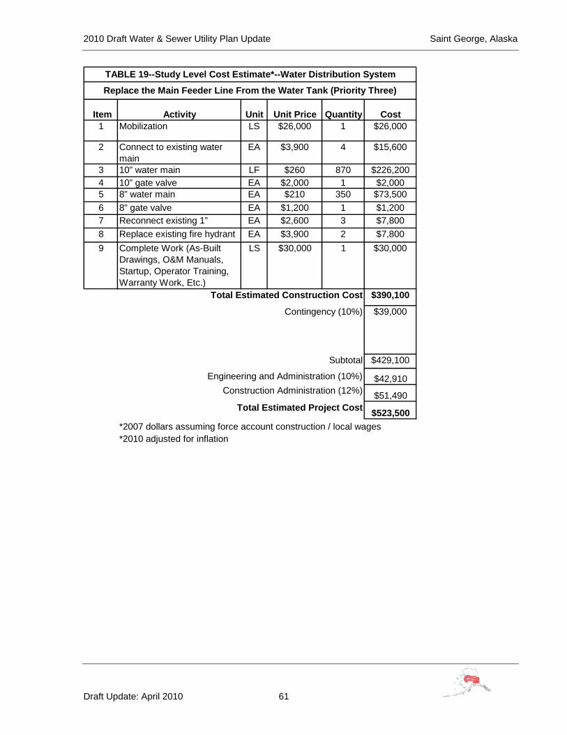
2010 Draft Water & Sewer Utility Plan Update Saint George, Alaska
Draft Update: April 2010 61
Item Activity Unit Unit Price Quantity Cost1 Mobilization LS $26,000 1 $26,000
2 Connect to existing water main
EA $3,900 4 $15,600
3 10” water main LF $260 870 $226,200 4 10” gate valve EA $2,000 1 $2,000 5 8” water main EA $210 350 $73,500 6 8” gate valve EA $1,200 1 $1,200 7 Reconnect existing 1” EA $2,600 3 $7,800 8 Replace existing fire hydrant EA $3,900 2 $7,800 9 Complete Work (As-Built
Drawings, O&M Manuals, Startup, Operator Training, Warranty Work, Etc.)
LS $30,000 1 $30,000
$390,100
$39,000
$429,100
$42,910
$51,490
$523,500
*2010 adjusted for inflation
TABLE 19--Study Level Cost Estimate*--Water Distribution System
Replace the Main Feeder Line From the Water Tank (Priority Three)
Engineering and Administration (10%)Construction Administration (12%)
Total Estimated Project Cost
*2007 dollars assuming force account construction / local wages
Total Estimated Construction Cost
Contingency (10%)
Subtotal
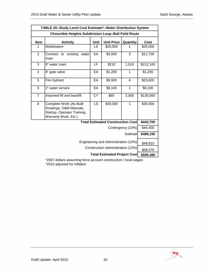
2010 Draft Water & Sewer Utility Plan Update Saint George, Alaska
Draft Update: April 2010 62
Item Activity Unit Unit Price Quantity Cost1 Mobilization LS $26,000 1 $26,000
2 Connect to existing watermain
EA $3,900 3 $11,700
3 8” water main LF $210 1,010 $212,100
4 8” gate valve EA $1,200 1 $1,200
5 Fire hydrant EA $5,900 4 $23,600
6 2” water service EA $9,100 1 $9,100
7 Imported fill and backfill CY $65 2,000 $130,000
8 Complete Work (As-Built Drawings, O&M Manuals, Startup, Operator Training, Warranty Work, Etc.)
LS $30,000 1 $30,000
$443,700$44,400
$488,100
$48,810
$58,570$595,480
TABLE 20--Study Level Cost Estimate*--Water Distribution SystemChoochkie Heights Subdivision Loop–Ball Field Route
Engineering and Administration (10%)
*2010 adjusted for inflation
Construction Administration (12%)
Total Estimated Project Cost*2007 dollars assuming force account construction / local wages
Total Estimated Construction CostContingency (10%)
Subtotal

2010 Draft Water & Sewer Utility Plan Update Saint George, Alaska
Draft Update: April 2010 63
Description Qty Unit Unit Cost Total CostMaterials (FOB St. George)
Side Shell Insulation2" x 2' x 8' insulation 175 EA $20 $3,500Pre-insulated (1-1/2") contoured thermal panels with embossed Aluminum skin
2800 SF $25 $70,000
Installation equipment 1 LOT $5,000 $5,000$78,500
Tank Roof Insulation2" x 2' x 8' insulation (2 layers)
300 EA $20 $6,000
Outer Galvanized Roof Deck and Hardware
2400 SF $12 $28,800
Other Hardware (new vent, railing extensions)
1 EA $5,000 $5,000
$39,800Labor
Superintendent 240 Hrs. $110 $26,400Local Hire Labor 240 Hrs. $42 $10,080Local Hire Labor 240 Hrs. $42 $10,080Local Hire Labor 240 Hrs. $42 $10,080
$56,640Equipment
Truck 30 Days $130 $3,900Hand Tools 1 Lot $5,500 $5,500
$9,400Subtotal (Materials + Labor + Equipment) $184,340
$7,370$22,120$3,690
$14,750$18,430
$250,700
Insulate City Water Storage TankIn 1998, the City of St. George constructed an un-insulated 277,800 Gallon (55' diameter x 16' tall) bolted steel water storage tank. During the winter months, icing within the tank has become a problem. This conceptual level cost estimate provides the
TABLE 21--Study Level Cost Estimate*--Water Storage
Contingency (10%)
*2010 adjusted for inflation
Total Project Cost*2007 dollars assuming force account construction / local wages
Construction Management, Insurance and Other Costs (12%)Engineering Costs (4%)
Inspection and Testing (2%)Support (8%)
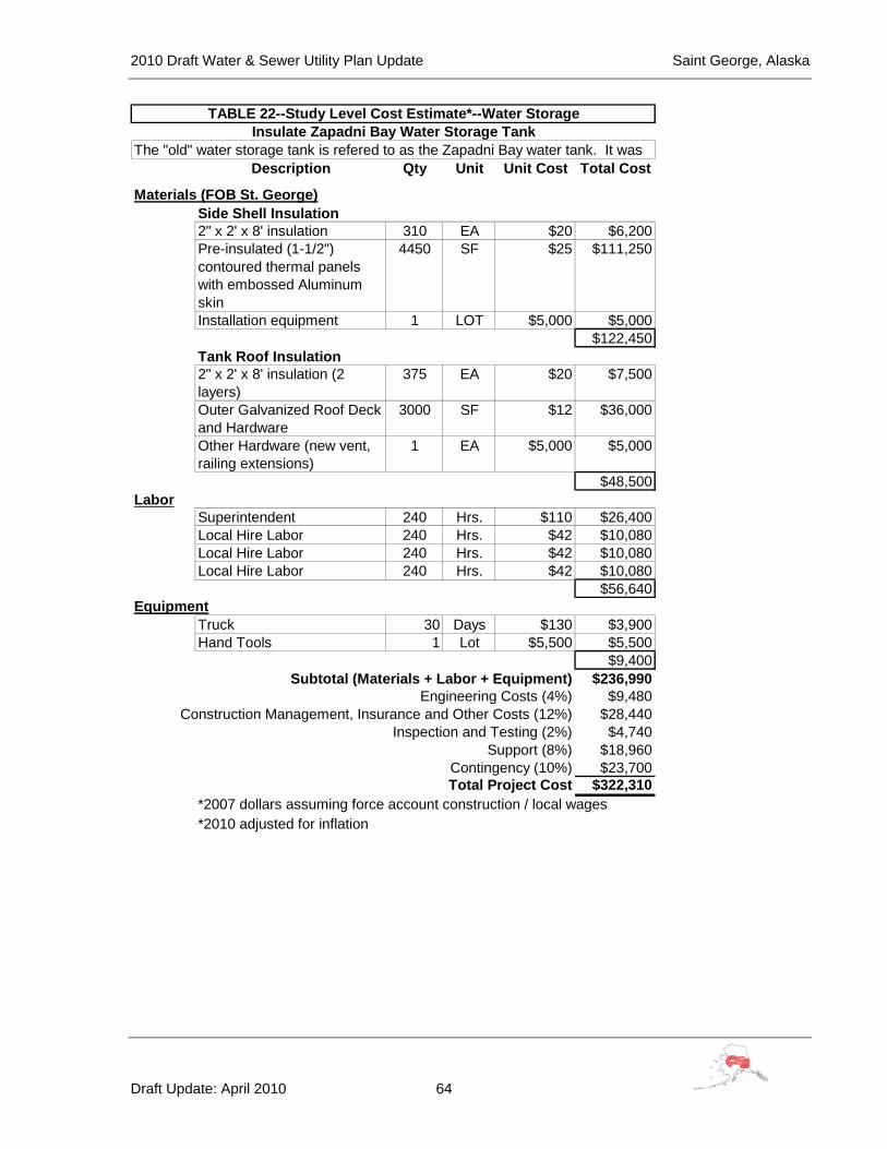
2010 Draft Water & Sewer Utility Plan Update Saint George, Alaska
Draft Update: April 2010 64
Description Qty Unit Unit Cost Total Cost
Materials (FOB St. George)Side Shell Insulation2" x 2' x 8' insulation 310 EA $20 $6,200Pre-insulated (1-1/2") contoured thermal panels with embossed Aluminum skin
4450 SF $25 $111,250
Installation equipment 1 LOT $5,000 $5,000$122,450
Tank Roof Insulation2" x 2' x 8' insulation (2 layers)
375 EA $20 $7,500
Outer Galvanized Roof Deck and Hardware
3000 SF $12 $36,000
Other Hardware (new vent, railing extensions)
1 EA $5,000 $5,000
$48,500Labor
Superintendent 240 Hrs. $110 $26,400Local Hire Labor 240 Hrs. $42 $10,080Local Hire Labor 240 Hrs. $42 $10,080Local Hire Labor 240 Hrs. $42 $10,080
$56,640Equipment
Truck 30 Days $130 $3,900Hand Tools 1 Lot $5,500 $5,500
$9,400Subtotal (Materials + Labor + Equipment) $236,990
$9,480$28,440$4,740
$18,960$23,700
$322,310*2007 dollars assuming force account construction / local wages
Engineering Costs (4%)Construction Management, Insurance and Other Costs (12%)
Inspection and Testing (2%)
Contingency (10%)Total Project Cost
Support (8%)
*2010 adjusted for inflation
TABLE 22--Study Level Cost Estimate*--Water StorageInsulate Zapadni Bay Water Storage Tank
The "old" water storage tank is refered to as the Zapadni Bay water tank. It was

2010 Draft Water & Sewer Utility Plan Update Saint George, Alaska
Draft Update: April 2010 65
Wastewater Collection System Improvements
The following table shows the study level estimated cost for constructing the
proposed sewer system improvements.
Item Activity Unit Unit Price Quantity Cost1 Mobilization LS $132,250 1 $132,250 2 Connect to existing manhole EA $2,600 2 $5,200 3 8” sewer main LF $200 4,175 $835,000 4 Manhole EA $10,400 24 $249,600 5 6” sewer service EA $7,800 1 $7,800 6 4” sewer service EA $6,500 49 $318,500 7 Install new water saver toilets EA $920 76 $69,920 8 Rock excavation CY $400 40 $16,000 9 Relocate existing utilities LS $52,000 1 $52,000 10 Road restoration LS $104,000 1 $104,000
11Procure 1250 Gallon Septage Pumping Vehicle EA $225,000 1 $225,000
12
Complete Work (As-Built Drawings, O&M Manuals, Startup, Operator Training, Warranty Work, Etc.)
LS $30,000 1 $30,000
$2,045,270$204,500
$2,249,770$224,980$269,970
$2,744,720
TABLE 23--Study Level Cost Estimate*--Sewer Collection SystemSewer Collection & Disposal Improvements
Engineering and Administration (10%)Construction Administration (12%)
Total Estimated Project Cost*2007 dollars assuming force account construction / local wages
Total Estimated Construction CostContingency (10%)
Subtotal
*2010 adjusted for inflation
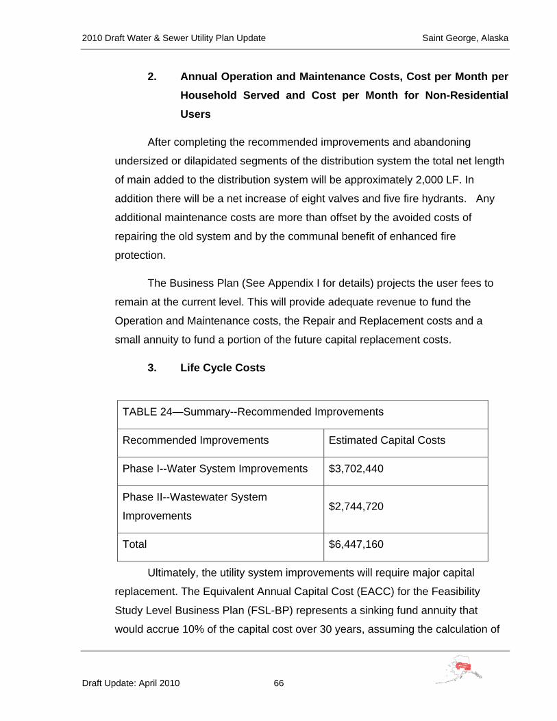
2010 Draft Water & Sewer Utility Plan Update Saint George, Alaska
Draft Update: April 2010 66
2. Annual Operation and Maintenance Costs, Cost per Month per Household Served and Cost per Month for Non-Residential Users
After completing the recommended improvements and abandoning
undersized or dilapidated segments of the distribution system the total net length
of main added to the distribution system will be approximately 2,000 LF. In
addition there will be a net increase of eight valves and five fire hydrants. Any
additional maintenance costs are more than offset by the avoided costs of
repairing the old system and by the communal benefit of enhanced fire
protection.
The Business Plan (See Appendix I for details) projects the user fees to
remain at the current level. This will provide adequate revenue to fund the
Operation and Maintenance costs, the Repair and Replacement costs and a
small annuity to fund a portion of the future capital replacement costs.
3. Life Cycle Costs
TABLE 24—Summary--Recommended Improvements
Recommended Improvements Estimated Capital Costs
Phase I--Water System Improvements $3,702,440
Phase II--Wastewater System
Improvements $2,744,720
Total $6,447,160
Ultimately, the utility system improvements will require major capital
replacement. The Equivalent Annual Capital Cost (EACC) for the Feasibility
Study Level Business Plan (FSL-BP) represents a sinking fund annuity that
would accrue 10% of the capital cost over 30 years, assuming the calculation of
2010 Draft Water & Sewer Utility Plan Update Saint George, Alaska
Draft Update: April 2010 67
Future Value (FV) at 2% inflation and the annual payment (PMT) at 3%
investment growth. For the proposed utility system improvements, 10% of the
Present Value (PV) of the Capital (CC) investment is $644,716. The FV is
$2,335,620 and the annual payment (PMT) is $49,090.
I. Review of Operational Costs for Similar Systems within Region
Saint George is a very remote location. Comparisons to similar systems are not
easy. The ambient temperature on the Island allows construction of water distribution
piping without the requirement of arctic insulation and heated and circulated supply.
This reduces operating costs. The remote location increases operating costs for supply
delivery, off site training and water testing.
The current residential rate of $57.00 for water and $31.50 for sewer per month
for compares favorably to rural communities throughout Alaska. Most small rural
Alaskan communities with recently installed systems are reporting unsubsidized rates
over $100.00 per month for both water and sewer service.
J. Advantages and Disadvantages
All of the proposed improvements are necessary to maintain a functional water
supply, treatment, storage and distribution and wastewater collection and treatment
system for Saint George. The major advantage will be a safe water supply. An
additional advantage will be reduced maintenance costs for leak repair and sewer
system cleaning. There are no disadvantages to the proposed improvements except
they do require a capital investment.

2010 Draft Water & Sewer Utility Plan Update Saint George, Alaska
Draft Update: April 2010 68
X. PUBLIC PARTICIPATION IN THE PLANNING PROCESS
A. Methods Used to Gain Community Input and Direction
Meetings of the City Council have discussed the alternatives and added their
suggestions to the required and desired improvements since the initial contract to map
the Water and Sewer systems was initiated in 2001. Contacts with Max Malavansky,
Sr., City Administrator and Alvin Merculief, Public Works Director are ongoing as repair
and maintenance needs of the failing systems are worked out. Most recently, April 11,
2007, the draft Water and Sewer Utility Plan Update was thoroughly reviewed in a work
session attended by all the City Council members. The improvements proposed in this
plan will assist the city to restore the confidence of the members of the community in the
adequacy and safety of their drinking water supply.
B. Identification of Community Goals and Objectives
The residents of Saint George have long had an adequate and safe drinking
water supply and reliable wastewater disposal. As many of the components of the
existing system have or are reaching their life expectancy, the reliability and the safety
of the system have deteriorated. The recently-identified pseudomonas bacteria
contamination of the water supply has caused great concern in the community. This
problem has caused the community to reevaluate the need for adequate and safe water
and wastewater systems. As with any community with a piped utility system, its failure
to deliver a safe and reliable product causes discomfort to its residents. In Saint George
this deterioration of quality has extended to out breaks of gastrointestinal illnesses and
the need to boil water for drinking purposes. The community, through the City Council,
has indicated that the first priority is the reestablish the adequacy and safety of the
water and wastewater systems.

2010 Draft Water & Sewer Utility Plan Update Saint George, Alaska
Draft Update: April 2010 69
XI. COMMUNITY BUSINESS PLAN FOR SELECTED ALTERNATIVE
The Business Plan has been prepared as a stand-alone document in the RUBA format
and is attached in Appendix I.
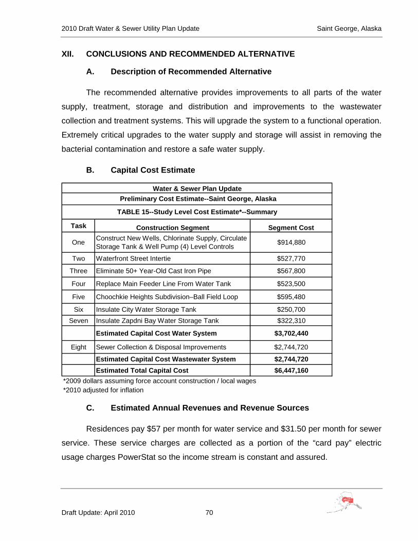
2010 Draft Water & Sewer Utility Plan Update Saint George, Alaska
Draft Update: April 2010 70
XII. CONCLUSIONS AND RECOMMENDED ALTERNATIVE
A. Description of Recommended Alternative
The recommended alternative provides improvements to all parts of the water
supply, treatment, storage and distribution and improvements to the wastewater
collection and treatment systems. This will upgrade the system to a functional operation.
Extremely critical upgrades to the water supply and storage will assist in removing the
bacterial contamination and restore a safe water supply.
B. Capital Cost Estimate
Task Construction Segment Segment Cost
One Construct New Wells, Chlorinate Supply, Circulate Storage Tank & Well Pump (4) Level Controls $914,880
Two Waterfront Street Intertie $527,770
Three Eliminate 50+ Year-Old Cast Iron Pipe $567,800
Four Replace Main Feeder Line From Water Tank $523,500
Five Choochkie Heights Subdivision–Ball Field Loop $595,480
Six Insulate City Water Storage Tank $250,700Seven Insulate Zapdni Bay Water Storage Tank $322,310
Estimated Capital Cost Water System $3,702,440
Eight Sewer Collection & Disposal Improvements $2,744,720
Estimated Capital Cost Wastewater System $2,744,720Estimated Total Capital Cost $6,447,160
*2009 dollars assuming force account construction / local wages
Water & Sewer Plan Update Preliminary Cost Estimate--Saint George, Alaska
TABLE 15--Study Level Cost Estimate*--Summary
*2010 adjusted for inflation
C. Estimated Annual Revenues and Revenue Sources
Residences pay $57 per month for water service and $31.50 per month for sewer
service. These service charges are collected as a portion of the “card pay” electric
usage charges PowerStat so the income stream is constant and assured.
2010 Draft Water & Sewer Utility Plan Update Saint George, Alaska
Draft Update: April 2010 71
D. Annual Operation and Maintenance Costs
The proposed improvements will substantially reduce system repair costs from
current levels. Projected expenses for Operation & Maintenance, Repair & Replacement
and an annuity payment for Capital Replacement Costs will be approximately $110,000.
The current revenue from the utility approximates this amount, so no rate increase is
projected. Expenditures for continuous repairs to the current system will be used to fund
a Capital Replacement Reserve once the system improvements have been completed.
See the Business Plan attached as Appendix I for more detail.
E. Capital Cost per Home Served
There are currently 76 active customers served by the Saint George Water and
Sewer Utility. 15 of these connections are seasonal, 18 are commercial/ institutional
(including the school) and 43 are full time residential. The proposed project cost per full
time connection is $6,447,160 / 61 = $105,691.

2010 Draft Water & Sewer Utility Plan Update Saint George, Alaska
Draft Update: April 2010 CE2 Engineers, Inc.
APPENDICES

2010 Draft Water & Sewer Utility Plan Update Saint George, Alaska
Draft Update: April 2010 A-1 CE2 Engineers, Inc.
Appendix A
Community Resolution Accepting
The Water & Sewer Utility Plan Update

2010 Draft Water & Sewer Utility Plan Update Saint George, Alaska
Draft Update: April 2010 B-1 CE2 Engineers, Inc.
Appendix B
Well Drilling Logs for Current Production Wells

2010 Draft Water & Sewer Utility Plan Update Saint George, Alaska
Draft Update: April 2010 C-1 CE2 Engineers, Inc.
Appendix C
Water Resources Reconnaissance--1976

2010 Draft Water & Sewer Utility Plan Update Saint George, Alaska
Draft Update: April 2010 D-1 CE2 Engineers, Inc.
Appendix D
Laboratory Analysis and Water Quality Data

2010 Draft Water & Sewer Utility Plan Update Saint George, Alaska
Draft Update: April 2010 E-1 CE2 Engineers, Inc.
Appendix E
Heterotrophic Plate Counts and Drinking Water Safety Chapters 6 & 11, World Health Organization

2010 Draft Water & Sewer Utility Plan Update Saint George, Alaska
Draft Update: April 2010 F-1 CE2 Engineers, Inc.
Appendix F
Plan Update Contacts

2010 Draft Water & Sewer Utility Plan Update Saint George, Alaska
Draft Update: April 2010 F-2 CE2 Engineers, Inc.
PLAN UPDATE CONTACTS
Timothy Law, P.E.
Village Safe Water
555 Cordova Street, 4th Floor
Anchorage, AK 99501
907-269-7607
Max Malavansky, City Administrator
City of Saint George
P.O. Box 929
Saint George, Alaska 99591
907.859.2263 Office
907.859.2212 Fax
907.240.0950 Cell
Doug Abbas
Remote Maintenance Worker
Aleutian Pribilof Islands Association, Inc.
201 East 3rd Avenue
Anchorage, Alaska 99501
907-222-4218
Michael Brubaker
Community Services Director
Aleutian Pribilof Islands Association,
Inc.
201 East 3rd Avenue
Anchorage, Alaska 99501
907-222-4217
Alvin Merculief, Mayor
City of Saint George
P.O. Box 929
Saint George, Alaska 99591
907.859.2263 Office
907.859.2212 Fax
Anna C Lestenkof, City Clerk
City of Saint George P.O. Box 929 Saint George, Alaska 99591 907.859.2263 Office 907.859.2212 Fax [email protected]
2010 Draft Water & Sewer Utility Plan Update Saint George, Alaska
Draft Update: April 2010 G-1 CE2 Engineers, Inc.
Appendix G
Community Sanitary Survey—2006

2010 Draft Water & Sewer Utility Plan Update Saint George, Alaska
Draft Update: April 2010 H-1 CE2 Engineers, Inc.
Appendix H
Community Rates, Charges, Rules & Regulations

2010 Draft Water & Sewer Utility Plan Update Saint George, Alaska
Draft Update: April 2010 I-1 CE2 Engineers, Inc.
Appendix I
Business Plan after Proposed Improvements