
S.A. COHEN, S. BERNABEI, R. BUDNY, T.K. CHU, P....
12
280 Journal of Nuclear Materials 128 & 129 (1984) 280-291 P~S~-~~RIA~ ~N~~~~ONS DURING RF E~~RI~ENTS IN TOKAMAKS S.A. COHEN, S. BERNABEI, R. BUDNY, T.K. CHU, P. COLESTOCK, E. HINNOV, W. HOOKE, J. HOSEA, D. HWANG, F. JOBES, D. MANOS, R. MOTLEY, D. RUZIC, J. STEVENS, B. STRATTON *, S. SUCKEWER, S. VON GOELER and R. WILSON Piosma Physics Loboratory, Princeton University, Princeton, New Jersey 08544, USA Key words: PWI, ICRF, LH Plasma-materials interactions studied in recent ICRF heating and lower hybrid current drive experiments are reviewed. The microscopic processes responsible for impurity generation are discussed. In ICRF experiments, improvements in machine operation and in antenna and f~t~~~ design have allowed efficient plasma heating at RF powers up to 3 MW. No significant loss of energy from the plasma core due to impurity radiation occurs. Lower hybrid current drive results in the generation and maintenance of hundreds of kiloamperes of plasma current carried by suprathermal electrons. The loss of these electrons and their role in impurity generation are assessed. Methods to avoid this problem are evaluated. 1. Introduction The application of high levels of radio frequency (RF) power to tokamak plasmas has produced major advances towards the realization of a steady state ther- monuclear reactor 111. The variety of RF waves that may exist in a tokamak and the resonant character of the heating allow control of the energy deposition pro- file [Z]. Heating of a selected species, for example, electrons or a particular type of ion, is possible. This permits enhanced fusion reactivity, as in a two-compo- nent plasma [3], and non-inductive current drive [4]. Another advantage of RF methods is the availability of high power components, such as power supplies and transmission lines, for several of the most desirable frequency ranges. The aforementioned and other achievements and be- nefits of RF methods have not been easily attained. To a large part, this is due to plasma-mate~aIs interactions (PMI). When plasmas are irradiated with electromag- netic waves whose energy density is comparable to the plasma’s, changes in the particle distribution functions can lead to increased particle and energy loss rates to the walls and other internal structures. They may, in turn, cause the contamination of the plasma by wall material. This detrimental effect may be inherent to fundamental processes or to aspects of a particular experimental configuration, e.g. antenna shielding. A great effort must be expended to discover this important difference, since the former problem is unavoidable while the latter is not. The diversity of RF experiments makes an exhaus- tive review of PM1 impractical. In this paper, we con- centrate on PMI during high-power ion-cyclotron- range-of-frequency (ICRF) heating and lower hybrid * John Hopkins University. 0022-3115/84/$03.00 @ Elsevier Science Publishers B.V. (North-Holland Physics Publishing Division) current drive (LHCD) experiments. Electron cyclotron heating, RF divertors, lower hybrid heating, fast-wave current drive, et cetera, though in the future may prove to be useful ways to ignite, sustain, or cleanse a toka- mak reactor, are not herein discussed. The main reason for their omission is the relative scarcity of PMI-related data. The plasma-materials interactions we consider are those that limit the coupling of RF power to the plasma and those that result in impurity generation. The first topic is generally of a technological nature- how can RF components be made to function appropriately in the vicinity of a magnetized plasma? The second topic is concerned with a possible detrimental side effect. Sec- tion 2 discusses PMI during present-day ICRF heating experiments. Sections 2.2 and 2.3 discuss component design and preparation and impurity generation. In section 3 the same subjects are discussed for lower-hy- brid current-drive experiments. 2. PMI during ICRF experiments 2.1. Experimental parameters and configurations The toroidal field of the tokamak, the Ze/m ratio of the resonant ion, and the desired harmonic of the fundamental cyclotron frequency determine the re- quired frequency of the RF generator. The lowest frequency commonly used on large tokamaks is about 25 MHz, which corresponds to H (snotty) heating at 17 kG, as in PLT [5], the highest frequency is about 150 MHz which is required for H (2nd harmonic) heating at 100 kG, as in Alcator C 161.The free space wavelengths for these frequencies are 12 and 2 m respectively. Thus, for present-day machines of 1 m typical scale, coaxial transmission lines and loop antennae are necessary to bring the RF power to the machine. The transmission
Transcript of S.A. COHEN, S. BERNABEI, R. BUDNY, T.K. CHU, P....

280 Journal of Nuclear Materials 128 & 129 (1984) 280-291
P~S~-~~RIA~ ~N~~~~ONS DURING RF E~~RI~ENTS IN TOKAMAKS
S.A. COHEN, S. BERNABEI, R. BUDNY, T.K. CHU, P. COLESTOCK, E. HINNOV, W. HOOKE, J. HOSEA, D. HWANG, F. JOBES, D. MANOS, R. MOTLEY, D. RUZIC, J. STEVENS, B. STRATTON *, S. SUCKEWER, S. VON GOELER and R. WILSON
Piosma Physics Loboratory, Princeton University, Princeton, New Jersey 08544, USA
Key words: PWI, ICRF, LH
Plasma-materials interactions studied in recent ICRF heating and lower hybrid current drive experiments are reviewed. The microscopic processes responsible for impurity generation are discussed. In ICRF experiments, improvements in machine operation and in antenna and f~t~~~ design have allowed efficient plasma heating at RF powers up to 3 MW. No significant loss of energy from the plasma core due to impurity radiation occurs. Lower hybrid current drive results in the generation and maintenance of hundreds of kiloamperes of plasma current carried by suprathermal electrons. The loss of these electrons and their role in impurity generation are assessed. Methods to avoid this problem are evaluated.
1. Introduction
The application of high levels of radio frequency (RF) power to tokamak plasmas has produced major advances towards the realization of a steady state ther- monuclear reactor 111. The variety of RF waves that may exist in a tokamak and the resonant character of the heating allow control of the energy deposition pro- file [Z]. Heating of a selected species, for example, electrons or a particular type of ion, is possible. This permits enhanced fusion reactivity, as in a two-compo- nent plasma [3], and non-inductive current drive [4]. Another advantage of RF methods is the availability of high power components, such as power supplies and transmission lines, for several of the most desirable frequency ranges.
The aforementioned and other achievements and be- nefits of RF methods have not been easily attained. To a large part, this is due to plasma-mate~aIs interactions (PMI). When plasmas are irradiated with electromag- netic waves whose energy density is comparable to the plasma’s, changes in the particle distribution functions can lead to increased particle and energy loss rates to the walls and other internal structures. They may, in turn, cause the contamination of the plasma by wall material. This detrimental effect may be inherent to fundamental processes or to aspects of a particular experimental configuration, e.g. antenna shielding. A great effort must be expended to discover this important difference, since the former problem is unavoidable while the latter is not.
The diversity of RF experiments makes an exhaus- tive review of PM1 impractical. In this paper, we con- centrate on PMI during high-power ion-cyclotron- range-of-frequency (ICRF) heating and lower hybrid
* John Hopkins University.
0022-3115/84/$03.00 @ Elsevier Science Publishers B.V. (North-Holland Physics Publishing Division)
current drive (LHCD) experiments. Electron cyclotron heating, RF divertors, lower hybrid heating, fast-wave current drive, et cetera, though in the future may prove to be useful ways to ignite, sustain, or cleanse a toka- mak reactor, are not herein discussed. The main reason for their omission is the relative scarcity of PMI-related data.
The plasma-materials interactions we consider are those that limit the coupling of RF power to the plasma and those that result in impurity generation. The first topic is generally of a technological nature- how can RF components be made to function appropriately in the vicinity of a magnetized plasma? The second topic is concerned with a possible detrimental side effect. Sec- tion 2 discusses PMI during present-day ICRF heating experiments. Sections 2.2 and 2.3 discuss component design and preparation and impurity generation. In section 3 the same subjects are discussed for lower-hy- brid current-drive experiments.
2. PMI during ICRF experiments
2.1. Experimental parameters and configurations
The toroidal field of the tokamak, the Ze/m ratio of the resonant ion, and the desired harmonic of the fundamental cyclotron frequency determine the re- quired frequency of the RF generator. The lowest frequency commonly used on large tokamaks is about 25 MHz, which corresponds to H (snotty) heating at 17 kG, as in PLT [5], the highest frequency is about 150 MHz which is required for H (2nd harmonic) heating at 100 kG, as in Alcator C 161. The free space wavelengths for these frequencies are 12 and 2 m respectively. Thus, for present-day machines of 1 m typical scale, coaxial transmission lines and loop antennae are necessary to bring the RF power to the machine. The transmission
S.A. Cohen et al. / Plasma-materials interactions during RF experiments 281
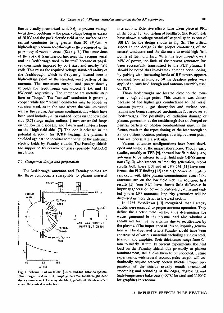
line is usually pressurized with SF, to prevent voltage breakdown problems - the peak voltage being in excess of 20 kV and the peak electric field at the surface of the central conductor being greater than 20 kV/cm. A high-voltage vacuum feedthrough is then required in the proximity of vacuum vessel. (See fig. 1.) The dimensions of the coaxial tr~s~ssion line near the vacuum vessel and the feedt~ou~ need to be small because of physi- cal constraints imposed by port sizes and nearby field coils. This raises the required voltage stand-off ability of the feedthrough, which is frequently located near a high-voltage point in the standing wave pattern of the antenna. The maximum current and power density through the feedthrough can exceed 1 kA and 15 kW/cm*, respectively. The antennae are metallic strip lines or “loops”. The “central” conductor is generally copper while the “return” conductor may be copper or stainless steel, as in the case where the vacuum vessel wall is the return. Antennae configurations which have been used include f-turn end-fed loops on the Iow field side [5,7] (large major radius), f-turn center-fed loops on the low field side [S], and $-turn and full-turn loops on the “high field side” [7]. The loop is oriented in the poloidal direction for ICRF heating. The plasma is shielded against the toroidal component of the antennae electric fields by Faraday shields. The Faraday shields are supported by ceramic or glass (possibly MACOR) insulators.
2.2. Component design and prepuration
The feedthrough, antennae and Faraday shields are the three components susceptible to plasma-material
F
ANTENNA CURRENT DISTRIBUTION (91
Ceramic Vacuum Feed
L I I
82 132 182
R km1
Fig. 1. Schematic of an ICRF $-turn end-fed antenna system. ‘Ibis design, used in PLT, employs ceramic feedthroughs near the vacuum vessel. Faraday shields, typically of stainless steel, cover the central conductor.
interactions. Extensive efforts have taken place at PPL in the design [8] and testing of feedthroughs. Bench tests have shown a voltage stand-off capability in excess of 100 kV for the design shown in fig. 2c. The critical aspect in the design is the proper contouring of the central conductor and the dielectric to avoid high field points at their interface. With this fee&rough over 1 MW of power, the limit of the present generator, has been successfully transmitted to the PLT plasma. It should be noted that in-tokamak antenna conditioning, by pulsing with increasing levels of RF power, appears essential. Several hundred 50 ms duration pulses were applied to each feedthrough and antenna assembly used on PLT.
These feedthroughs are located close to the torus near a high-voltage point. This location was chosen because of the higher gas conductance to the vessel vacuum pumps - gas desorption and surface con- t~nation being suspected rn~h~srns for arc-over at feedthroughs. The possibility of radiation damage or plasma generation at the feedthrough due to charged or neutral particle or photon bombardment may, in the future, result in the repositioning of the feedthrough to a more distant location, perhaps at a high-current point. This will necessitate a redesign.
Various antennae configurations have been devel- oped and tested at the major laboratories. Though early studies, notably at TFR [9], showed low field side (LFS) antennae to be inferior to high field side (HFS) anten- nae (fig. 3) with respect to impurity generation, recent results both there [lo] and at ET-2M [ll] have con- firmed the PLT finding [12] that high power RF heating can occur with little plasma conta~nation even if the antennae are on the low field side. In addition, first results [5] from PLT have shown little difference in impurity generation between center-fed a-turn and end- fed i-turn LFS antennae. Impurity generation will be discussed in more detail in the next section.
In 1965 Yoshikawa [13] recognized that Faraday shields were essential to proper antenna operation. They define the electric field vector, thus determining the waves generated in the plasma, and aiso whether a sheath will form at the antenna due to rectification by the plasma. (The importance of this to impurity genera- tion will be discussed later.) Faraday shield have been constructed of various materials including stainless steel, titanium and graphite. Their thicknesses range from 0.1 mm to nearly 10 mm. In present experiments, the heat load on the Faraday shield, due primarily to plasma bombardment, still allows them to be uncooled. Future experiments, with several seconds pulse length, will un- doubtedly require actively cooled shields. Proper pre- paration of the shields usually entails mechanical smoothing and rounding of the edges, degreasing and high-temperature bake-outs (4OO“C for steel and llOO°C for graphite) in vacuum.
4. IMPURITY EFFECTS IN RF HEATING

282 S.A. Cohen ef al. / Plasma-materials rnferaciions during RF experiments
GAS
Fig. 2. Cross section of three feedthroughs designed for PLT. The design shown at the bottom has successfully stood-off 100 kV in a test stand and transmitted 1 MW of power at 25 MHz into PLT plasmas (81.
2.3. Impurity generation professes
Before discussing the mechanisms responsible for impurity generation, it is proper to assess the impor- tance of impurities in present ICRF heating experi- ments. Though some ICRF experiments had once been plagued with impurity problems caused, in part, by inadequate wall and component designs and condi-
tioning techniques and tokamak operating routines, all major experiments have now achieved conditions wherein, for MW heating levels, efficient ion heating is attained and the radiated power from impurities in the plasma core is less than 10% of the power input to the core. The radiative power toss from the entire plasma is due to contamination by both high and low Z impuri- ties. As shown in fig. 4, radiation from the plasma is

S.A. Cohen et al. / Plmma - materkak interactions during RF experimenis 283
Fig. 3. (top) View of the TFR f-turn end-fed LFS antenna. (bottom) Details of the cross section. The main improvements in this design are carbon rails (4) which protect the sides of thick Faraday shields (3). The return conductor is indicated as (1) in the figure [9].
emitted primarily from the periphery [5] by low 2 contaminants, and accounts for about 30% of the total input power. This is generally considered a desirable mode of operation, since it distributes the heat load uniformly on the walls and reduces direct local&d plasma embedment of the walls and limiters. The amount of radiated power scales linearly with RF power (141 (fig. 5). Modelling of the impurity radiation in TFR [lo] gives central metal ion densities of - 2 X 10” cme3 and carbon and oxygen ion densities of - 2 x 10¹² cme3 in a plasma with n,(O)= 1.1 x 10¹⁴ cme3. This represents a Z,,, - 2.5 and a 20% depletion’ of hydro-
Of 0 200 400 600 800
TIME (msec)
0.2
W/cm3 0. I
0 -50 0 50
Pi_1 MINOR RADIUS (cm)
Fig. 4. Total radiated power and abel inverted profiles during 3He minority heating at PaF - 700 kW. The profiles were taken about 200 ms after the RF was turned on [5].
gtic ions. The high Z,, and deuteron depletion would both severely impact a reactor. Thus, although high and low 2 impurities do not significantly affect the power balance in the present multi-MW experiments, it is necessary to understand their origins to ensure that future experiments with higher powers and longer pulses are not impeded.
The four primary microscopic processes by which ICRF heating can cause impurity generation are arcing, evaporation, ion sputtering and charge exchange neutral sputtering. Arcing is judged to be of little consequence in a well-conditioned ICRF system based on the time behavior of the impurity radiation. Indeed, photo- graphic recording in PLT of the antennae structures during high-power heating show no flashes indicative of arcs. Evaporation, too, is of little consequence except during low density conditions where Severe runaway electron bombardment may occur. This situation may not be true in the near future when long-pulse high- power ICRF heating systems are put into operation. Then both the limiter (or divertor) heat removal systems and the antenna structures will require active cooling.
Sputtering by ions has been judged by several groups [lO,ll] to be an important cause of impurities. Ions which leave the main body of the plasma impact on the material surfaces nearest the edge plasma. In addition to the limiters, the antennae are placed near tlie plasma edge because the coupling between the antenna and the
4. IMPURITY EFFECTS IN RF HEATING

S.A. Cohen et al. / Plasma - materials interaciions during RF experiments
i-
I I
H* 2NDHormonic ICRF
I I
I 2 ICRF POWER(MW)
t 2 ICRF POWER(MW)
3
Fig. 5. Total radiated power and brightness of several impurity lines versus RF power during second harmonic heating at ii, = 3.8 x lo”, B, = 14 kG [S] on PLT.
plasma improves as the distance between them is re- duced, the scale distance being of order O.l(k,)-* = 5 cm. Thus ICRF antennae are of necessity immersed in the edge plasma at a distance of - 5 cm outside the
*I I I I I I I 2 3 4 5 6 7
d km)
Fig. 6. Loading resistanct of the JET-TFR antenna versus the distance between the plasma boundary and the central conduc- tor (full curve, theory; open circles, experiment) [7].
l Without ICRF
J 19 20 21 22 23 24 25 26 27
r (em)
Fig. 7. Fkctron temperature profile measured in the TFR pIasma edge with double Langmuir probes [7].
limiter radius. The calculated and experimental loading resistance for the TFR [lo] HFS side antenna, shown in fig. 6, clearly indicate the change in coupling with distance between the antenna and the plasma.
The edge plasma electron temperature and density are shown in figs. 7 and 8 for ICRF heating of TFR [lo] at ii, - 1 x lOI4 cmw3, and ZP - 200 kA. Both T, and the density scrape-off distance, A,, are seen to double for P,, - 300 kW. Similar results have been seen on
AgsO.7 cm
?
.
dO~ I I I I I \I
I9 20 21 22 23 24 25 26
r km!
Fig. 8. Electron density profiles in the TFR scrape-off plasma as measured for ohmic and ICRF-heated plasmas. The limiter is at 19.5 cm [7].

S.A. Cohen et at. / Plasma-materials interactions during RF experiments 28s
I i I J 200 400 600
P,, (kW) 401 1 8 1 I
0 0
30 0 0 0
5 c1 20
P
1~: l
lif )EI_I
10 ??!I!
0 , , t 0 200 400 600
PRf fkW
Fig. 9. Power dependence of the electron density and tempera- ture in the JFT-2N edge plasma. The background levels for T, are indicated for both neutral-beam injection (NBI) and ohmic heating (OH) [ll].
PLT [IS] and ATC [16] for Ah,, but not AT,. Power dependences of AT, and Ah,= have been studied in TFR and JFT-2M and found to be similar. Results from the latter are shown in fig. 9. For the parameters h - 1 cm and Te - 5 eV, the stored energy in the plasma edge is only 5 1 J.
The ions which strike the limiters, RF antennae and walls impact with an energy equal to the sum of their kinetic energy plus Z times the sheath potential. The sheath potential may be several (typically four) times T,
or it may reach a substantial fraction of the peak antenna voltage. This latter condition exists if plasma rectification of the RF occurs as in the absence of grounded Faraday shields. The ions which strike the limiters can be categorized into three classes: thermal hydrogen& thermal impurities, and suprathermal hy- drogen&. Using probes at the limiter radius, the edge plasma ion temperature during earlier experiments has been measured to be 20-200 eV [17,18]. However, no data have been presented for the highest (3 MW) powers recently attained. Using the TFR edge parameters and assuming Ti (a) = 50 eV, a deuterium plasma, an impur- ity confinement time of 20 ms, sputtering yields for clean metals [19], and a poloidally uniform flux, TFR estimates the volume averaged impurity density from a carbon ring limiter to be 5 x 10” cmv3, and 5 x 10” crnv3 for a steel ring liter. If ‘Z’i(u) = 175 eV the carbon density would be 10 X higher and the iron
density 100 X higher. Because of this agreement (factor of 2) between these estimated and the observed impurity levels and also because of a positive correlation between impurity species and Faraday shield material, the TFR group confirmed the PLT conclusion that thermal hy- drogenic ion sputtering of B-normal surfaces, especially the limiter and Faraday shields, is the main cause of their impurities.
The JFT-2M team [ll] has reached a somewhat different conclusion because of the power dependence of the impurity concentrations and a positive correla- tion between light (C, 0) and heavy (Fe, Ni) impurity levels in ICRF-heated discharges. They describe the influx of metal impurities as being due to the impact of multiply-charged C and 0 ions. Only at the highest RF power is proton sputtering important. In contrast, the TFR team has purposely contaminated their discharge with Ne in an attempt to see this phenomena [9], but they saw no significant ( < 10%) change in the metal impurity level.
Manos et al. {20] and Hammett et al. [Zl] have investigated the loss of suprathermal ions from the PLT. In 2nd harmonic H+ heating they see the loss of - 90 keV banana trapped ions. No similar losses are ob- served for minority heating of He3 in a D plasma. The loss during 2nd harmonic H+ heating is not poloidally symmetric, but is concentrated at the outside midplane position [22]. The direct sputtering by these energetic ions is estimated to be unimportant for impurity genera- tion, both because of the low yield (10e4) and the low flux (1 X lo’* -, 4 X 10¹⁹ s-l}. However, a synergistic interaction between the heat deposited by these en-
‘*16*
TIME (msec)
Fig. 10. Charge exchange D” efflux as a function of time for three cases during ICRF minority heating of D-He3 plasmas with P,, = 1 MW. The flux is integrated over the energy range 25 to 1000 eV. A and B are observations away from the limiters. C are observations near an auxiliary limiter [IS].
4. IMPURITY EFFECTS IN RF HEATING

286 S.A. Cohen et al. / Plasma-materials interactions dwing RF experiments
Heoting 3
,,i~ 0 5 IO 15 20 25 30 35
E(keV)
Fig. 11. Charge exchange flux spectra in PLT for ohmically
heated and ICRF-heated (Par = 1 MW) plasmas.
ergetic ions and the momentum deposited by thermal ions may cause enhanced evaporative sputtering [22].
The final mechanism possibly responsible for impur- ity generation is sputtering by neutrals. A low energy neutral atom spectrometer 1231 has been used on PLT to study the efflux of charge-exchange neutrals during ICRF experiments (151. The efflux increases at a rate of - 1015 cme2 s-l MW-’ during both 2nd harmonic and minority heating. In fig. 10 one can see that the increase in flux, AT, is toroidahy symmetric. The cause of this efflux is the increase of ion density near the vessel wall, which leads to enhanced neutralization and a higher neutral density. The rise in ai may be due to en- hanced transport.
The charge exchange measurements show an increase across the entire spectrum, from 20 to 50000 eV, with the largest percentage increase at the highest energies (fig. 11). Using the sputtering yields for clean metals, the increase in flux can account for the observed in- crease in wall material found during ICRF heating. Fig. 12 shows a portion of the UV spectrum before and during ICRF heating. Increases in Ti and Fe, presuma- bly from the wall, are evident. Increase in C and 0, presumably from the limiter, are also seen. The charge exchange effiux may also be responsible for the sputter- ing of Faraday shield material previously coated around the tokamaks by ion sputtering or evaporation. The
Fig. 12. Spectra of the 110 to 175 A region before (t = 400 ms)
and during (t = 600 ms) ICRF heating in the I-I+ minority
regime at P,, = 2 MW in PLT. The antennae had titanium Faraday shields [14].
charge exchange effIux is observed to have an inverse dependence with plasma current. Ion heating efficiency behaves in an opposite fashion, i.e., in PLT good ion heating only occurs for I,, 2 300 kA.
In summary, high power heating of tokamak plasmas by ICRF techniques has increased the central ion tem-
perature at a rate between 3 and 6 eV/kW X lOi cmw3.
20-
i8- i Y
16-
H+Minarity Made 850 kl
Ti
0 Stoinlsss Steel Faroday Shields
@ Titanium Foraday Shields
Ti
6-
4-
2-
O- L
!
Fig. 13. A comparison of the total titanium and iron densities before and during ICRP heating in FLT. As indicated, the antennae had either titanium or stainless steel Faraday shields
u41.
Before ICRF During ICRF

S.A. Cohen ei al. / Plavna - materials interactions during RF experiments 287
To achieve this, major improvements had to be made in feedthrough and antenna designs. Operation with a “good” target plasma is also essential, the main parame- ter being a high plasma current. The impurity flux into these discharges has not affected the power balance in the plasma core, but does cause enhanced radiation from the plasma periphery and some depletion of the hydrogen ions in the core. The structures which are the sources of these impurities are the limiters, Faraday shields, other objects within a few centimeters of r= a, and the walls. The structures close to the plasma are sputtered by thermal ion bombardment and possibly multiply charged impurities. The wall is sputtered by charge exchange neutrals. Fig. 13 shows the effects on impurity levels of changing Faraday shield material in PLT.
3. PM1 during LHCD experiments
3.1. Experimental parameters and configurations
The requirement that - 1 MW of RF power must be injected through - 20 cm ports, sets the power density at 5; lo4 kW/cm2 and the peak electric field at 2 4 X
lo3 V/cm. The transmission line from the generator to the vicinity of the tokamak is pressurized with dry air to prevent high voltage breakdown. A waveguide window vacuum break is required in place of the coaxial feedthrough used in ICRF. The RF power is finally brought to the vacuum vessel through an array of closely
Lower hybrid waves in a plasma may be absorbed by electron Landau damping. This transfer of energy and momentum to electrons which resonant with the lower
spaced waveguides. Phasing the array allows one to
hybrid waves’ phase velocity has enabled the generation [24] and sustentation [25] of currents in tokamak plas-
launch the lower hybrid waves predominately in one
mas. To propagate, the frequency of lower hybrid waves must be above the lower hybrid resonance frequency
direction for current drive. Fig. 14 shows a schematic of
and below the electron cyclotron and plasma frequen- cies. For present tokamaks, this is in the range 200
the major components.
MHz -+ 30 GHz. Powerful generators are available in the middle of this range at f= 800 MHz, 1.5 GHz, 2.45 GHz, and 4.6 GHz at which frequencies the free space wavelengths are 37, 20, 12, and 6.5 cm respectively. Thus waveguides are appropriate transmission line to carry the power to the machines and waveguide launchers are suitable antennae.
The current drive efficiency, as derived by Fisch [26] can be written
I(MA) 0.35&, p=p P(MW) Rn ’ 20
where E,,, is the average energy of the resonant elec-
TO
Generator
Tokamok
Voccum
Vessel
Fig. 14. Schematic of a typical lower hybrid system. The waveguide section between the generator and the window may be pressurized with dry N, or SF, to prevent arcing.
trons (in units of 100 keV), R is the major radius (in meters) and ii, is the average density (in units of 10” mw3). Because of this inverse dependence on n and a density limit, n,_, on wave propa~tion [27], current drive experiments are usually run at lower densities than the peak value attainable in many machines. Present experiments [28] indicate that the density limit increases with 02. In PLT, for example, 800 MHz LHCD experi- ments are carried out below a critical density 7i, = 8 X
lOi crne3. in Alcator C, LHCD [6] is possible at densities up to nc = 1 X lOI cmm3 because a frequency of 4.6 GHz is used. At these reduced densities, both the energy and particle confinement times are also below their peak values. This affects the power loading on the vessel components both through the loss of thermal plasma and the lower-hyb~d-groats tail electrons. At the highest powers yet used, 1 MW in Alcator C and - 600 kW in PLT, the central electron temperature was - 1 keV and the energy confinement time was - 10 ms. The average energy of the electron tail was - 100 keV.
3.2. Component design and preparation
The waveguide array (launcher), the waveguide walls and the RF window are the main RF components susceptible to plasma-surface interactions. The launcher is immersed in the edge plasma to a position where o < Ok (n, 2 10” crnw3 for PLT) in order that a propa- gating wave be generated. This positions the array about
In a fusion reactor the RF windows will be placed far from the tokamak to avoid radiation damage. (Here commercial high power klystron windows can be used.)
l-2 cm outside the limiter. The coupling of power to
This, however, leads to evacuated waveguides passing
the plasma is critically dependent on this distance as
through regions of low magnetic field where o = w,,. Here the phenomena of m~tipacto~ng, secondary elec-
shown in fig. 15. The front face of the array is curved to match the minor radius of the plasma. No systematic study of this feature has yet been published. We note that this shaping and the sensitivity to ii, make the plasma position a critical parameter to control.
4. IMPURITY EFFECT8 IN RF HEATING
288 S.A. Cohen et al. / Plasma- moterials interactions during RF experiments
2.0 2.5 PLASMA TO WAVEGUIDE DISTANCE (cm)
3.c
Fig. 15. Calculated reflection for an 8-waveguide array launch-
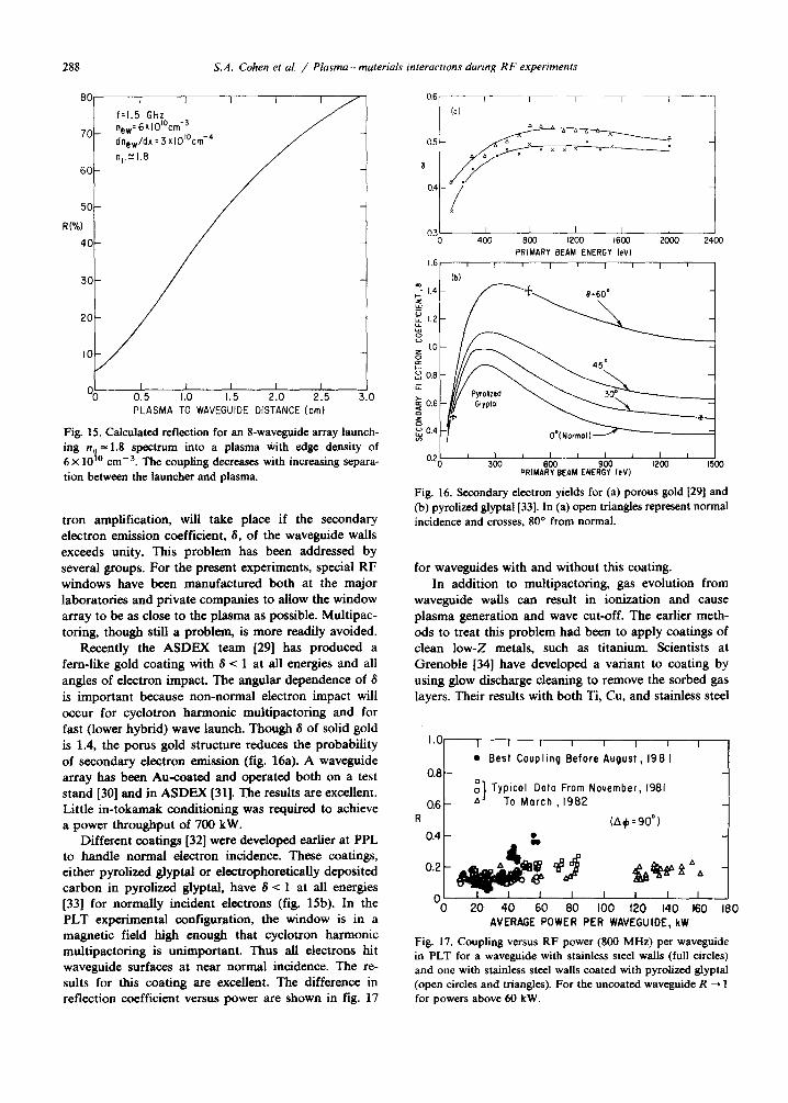
ing n =1.8 spectrum into a plasma with edge density of 6 X 10 Y0 cm-3. The coupling decreases with increasing separa- tion between the launcher and plasma.
tron amplification, will take place if the secondary electron emission coefficient, S, of the waveguide walls exceeds unity. This problem has been addressed by several groups. For the present experiments, special RF windows have been manufactured both at the major laboratories and private companies to allow the window array to be as close to the plasma as possible. Multipac- toting, though still a problem, is more readily avoided.
Recently the ASDEX team [29] has produced a fern-like gold coating with S < 1 at all energies and all angles of electron impact. The angular dependence of S is important because non-normal electron impact will occur for cyclotron harmonic multipactoring and for fast (lower hybrid) wave launch. Though 6 of solid gold is 1.4, the porus gold structure reduces the probability of secondary electron emission (fig. 16a). A waveguide array has been Au-coated and operated both on a test stand (301 and in ASDEX [31]. The results are excellent. Little in-tokamak conditioning was required to achieve a power throughput of 700 kW.
Different coatings [32] were developed earlier at PPL to handle normal electron incidence. These coatings, either pyrolized glyptal or electrophoretically deposited carbon in pyrolized glyptal, have 6 < 1 at all energies [33] for normally incident electrons (fig. 15b). In the PLT experimental configuration, the window is in a magnetic field high enough that cyclotron harmonic multipactoring is unimportant. Thus all electrons hit waveguide surfaces at near normal incidence. The re- sults for this coating are excellent. The difference in reflection coefficient versus power are shown in fig. 17
0.3 I I I I I
0 400 800 1200 1600 2cal 2400
PRIMARY BEAM ENERGY (et’1
1.6 I , t I f I I 1 1
Ib)
‘0. 1.4-
5
z 1.2- Y z
5 1.0 -
F : 0.8 -
Ii
0.2; ’ ’ t I I I 1 I I 300
PRlMAt?3EAM ENEiG? Irk’) I200 1500
Fig. 16. Secondary electron yields for (a) porous gold 1291 and
(b) pyrolized glyptal[33]. In (a) open triangles represent normal incidence and crosses, 80’ from normal.
for waveguides with and without this coating. In addition to multipactoring, gas evolution from
waveguide walls can result in ionization and cause plasma generation and wave cut-off. The earlier meth- ods to treat this problem had been to apply coatings of clean low-Z metals, such as titanium. Scientists at Grenoble [34] have developed a variant to coating by using glow discharge cleaning to remove the sorbed gas layers. Their results with both Ti, Cu, and stainless steel
l Best Coupling Before August, 198 I
“0 20 40 60 80 100 120 140 160 180 AVERAGE POWER PER WAVEGUIOE, kW
Fig. 17. Coupling versus RF power (800 MHz) per waveguide in PLT for a waveguide with stainless steel walls (full circles) and one with stainless steel walls coated with pyrolized glyptal (open circles and triangles). For the uncoated waveguide R + 1 for powers above 60 kW.

S.A. Cohen et al. / Plasma-materials interactions during RF experiments 289
waveguides have been remarkable. Record power densi- ties [35], 12 kW/cm’, and electric fields, 10 kV/cm, have been achieved in a test bed. Lowering of 6 has also been achieved. This result has been interpreted as being due to increased surface roughness induced by the argon glow discharge.
3.3. Impurity generation processes
The usual effects of impurities in plasmas are to reduce the energy confinement time via radiation and to decrease the hydrogen concentration at constant p. In present LHCD experiments neither of these is im- portant because of the low density which results in little electron impact excitation and no /I limit. Two im- portant impurity-related effects are however observed during LHCD. The first is a decrease in current drive efficiency, possibly due to enhanced ohmic dissipation by the slideaways or to surface losses via collisional damping of the wave. In Alcator C [6] a 40% lower current drive efficiency is measured for discharges with C or Sic limiters than for those with MO limiters. The second effect is a complete cessation of current drive when ne rises above its critical value, as by the addition
1.0 I I , 1 1 I I I I 1250
150 0 0.2 0.4 0.6 0.8 1.0
TIMEtsec)
1 I 1 I ! I , , I
L.H 325 kW
n 1
0 0.2 0.4 0.6 0.0 I.0 TIME (sac)
Fig. 18. Time evolution of the electron density, plasma current and CV radiation during a LHCD discharge in PLT. The RF power was on from 400 to 600 ms. The carbon influx is caused by localized evaporation from a carbon limiter.
, - YpAY, AqwY”“~XDO*lOm o”9” ro-
0 100 200 300 400 ENERGY (keV)
Fig. 19. Spectra of X-ray photon emission from PLT during
LHCD experiments. The relative phasing of the waveguide
array results in a different energy distribution for the energetic
electrons responsible for the X-ray emission.
of the electrons from the impurities. This latter effect is shown in fig. 19. A carbon influx raises nc during this particular experiment. By 450 ms into the discharge, the current ramp-up rate produced by 300 kW net of LH power has decreased to zero. Methods to avoid both these problems have been recently set forth and will be discussed at the end of this section.
The impurity generation processes to be evaluated for LHCD are same as for ICRF: arcing, evaporation, ion sputtering and charge exchange sputtering. Arcing in the main vessel is rarely seen and is not considered a problem. Observations of apparent arcs occurring near the waveguide mouth have been made. The arcs are irreproducible and infrequent.
Evaporation is judged to be a major cause of impur- ity generation. LHCD results in the formation of an energetic electron tail of 100 keV typical energy (fig. 19). The confinement of energetic electrons has been measured by Barnes [36]. For 0.4-1.0 MeV runaways generated inductively, he finds a confinement time of 2-6 ms (fig. 20). Preliminary results [37] on LH gener- ated tail electrons give a confinement time somewhat longer, about 25 ms. The slowing down time for these electrons on the background thermal plasma is about 20 -+ 200 ms. The point, then, is that some energetic electrons will leave the plasma. In addition, acceleration of already energetic electrons may occur in the edge plasma thus increasing the likelihood of the loss of energetic electrons. It has been noted [36,39] that the higher u,, of a species the shorter the scrape-off distance. For electrons of 100 keV parallel energy, the scrape-off distance is about 0.1 mm. The net result in a con- centrated heat load by the lost energetic electrons on the material object nearest the plasma edge. In PLT this is generally a carbon limiter. Photographic recording using standard TV/video and film techniques have clearly shown the formation of an incandescent hot spot on the PLT limiters. The hot spot can be moved from
4. IMPURITY EFFECTS IN RF HEATING

290 S.A. Cohen et al. / Plasma- materials tnteractions during RF experiments
I 0 Global, Equilibrium
q Edge, Equilibrium
q Global, Time Depe
+I----/ Oscillations ““t?ji
I \ Odd Mode ‘$ I Sowteeth
I hool
I \I I / I
0.0 I 0.1 I IO IO0
ELECTRON ENERGY (MeV)
Fig. 20. Confinement time versus energy of electrons in PLT
[361.
tne cop to the bottom to the outside midplane limiter by shifting the plasma position appropriately. The surface temperature, T,, has been estimated from the spot brightness to be T, = 2500 K. At this temperature evaporation can readily cause the observed carbon con- tamination in the plasma.
Ion sputtering is estimated to be a less important impurity source, both from the limiters and the wave- guides. At the low densities and short particle confine- ment time, these impurity densities should be - 10’ times lower than in ICRF-heated discharges. In addi- tion, in test bed experiments [40,41] the effect of the wave directly in front of the waveguide has been evaluated. The plasma density has been found to de- crease at RF power levels greater than 1 kW/cm*. This
occurs because the “RF pressure” becomes comparable to the electron pressure. A positive potential also builds up. The net effect should be a decrease in the ion flwc to the waveguide and reduced ion sputtering.
Charge exchange sputtering has been evaluated on PLT [42] using neutral particle diagnostics. For lo’* < iI, i 1013 cme3 no large increase in the charge exchange outflw has been observed during LHCD. At these low densities, the charge exchange flw is toroidally uniform and has an average energy twice higher than during higher density (10’” -Z A, < 10” cmm3) operation. The predicted Fe concentration is - 5 x 1O’O cmv3, giving z,, = 3.
Thus the two main causes of impurities are evapora- tion due to energetic electron impact and sputtering due to charge exchange hydrogen bombardment. This latter process will become less important at higher densities, in part because. of the drop in average energy with increased plasma opacity, and in part due to the in- crease in particle confinement time. The first process, though, has been tentatively identified in Alcator C
which already operates at the high densities envisioned for reactors. It thus appears that energetic slideaways will be lost from tokamaks with reactor-like parameters.
To reduce the temperature rise on a small area of the limiter the plasma could be moved thus shifting the tangency point. However, this will alter the LH cou- pling. The converse, to move the limiter, has recently been suggested and tried on PLT. The limiter shape must be specially tailored such that the tangency point is near the limiter circumference. Then, for example, by rotating the limiter, the heat load can be readily distrib- uted over a larger area. The successful implementation
of this concept has been reported [43].
Acknowledgment
We wish to thank J. Adam, G. Tonon, M. Keil- hacker, D. Eckhartt, J. Jacquinot, and K. Odajima for sending versions of unpublished papers. This work was supported by the US Department of Energy Contract No. DE-AC02-76-CHO-3073.
References
[l] D. Hwang and J.R. Wilson, Proc. IEEE 69 (1981) 1030. [2] P. Cole-stock et al., Proc. 2nd Joint Grenoble-Varenna
Intern. Symp. on Heating in Toroidal Devices, Como, 1980, Vol. 1.
[3] J.M. Dawson, H.P. Furth and F.H. Tenney, Phys. Rev. Lett. 26 (1971) 1156.
[4] N.J. Fisch, Phys. Rev. Lett. 41 (1978) 783. [S] J. Hosea et al., Proc. Fourth Intern. Symp. on Heating in
Toroidal Plasmas, Rome, 1984, Vol. 1, p. 261. [6] M. Porkolab et al., Proc. Fourth Intern. Symp. on Heating
in Toroidal Plasmas, Rome, 1984, Vol. I, p. 529. [7] TFR group, EUR-CEA-FC-1219 (March 1984). [S] D. Hwang et al., J. Vat. Sci. Technol. 20 (1982) 1273. [9] TFR Group, 11th European Conf. on Plasma Physics and
Controlled Fusion, Aachen 26, 1A (1984) p. 165. [lo] TFR Group, Proc. Fourth Intern. Symp. on Heating in
Toroidal Plasmas, Rome, 1984, Vol. I, p. 277. (111 K. Odajima et al., Proc. Fourth Intern. Symp. on Heating
in Toroidal Plasmas, Rome, 1984, Vol I, p. 243. [12] D. Hwang et al., in: Plasma Physics on Controlled Fusion
Research, Baltimore, 1982, Vol. 2 (IAEA, Vienna, 1983) p. 3.
[13] S. Yoshikawa, M.A. Rothman and R.M. Sinclair, Phys. Rev. Lett. 14 (1%5) 214, and MATT 373 (1965).
[14] B. Stratton et al., Nucl. Fusion 24 (1984) 767. (IS] S. Cohen et al., submitted to Nucl. Fusion. [16] H. Hsuan et al., Proc. 3rd Conf. on RF Plasma Heating,
UCLA press. Pasadena (1978). (171 G. Staudenmaier, P. Staib and W. Poschenrieder, J. Nucl.
Mater. 93-94(1980) 121; P. Staib, J. Nucl. Mater. 111-112 (1982) 109.
(18) S.A. Cohen, H.F. Dylla, W.R. Wampler and C.W. Magee, J. Nucl. Mater. 93-94 (1980) 109.
(19) J. Bohdansky, J. Roth and H.L. Bey, J. Appl. Phys. 51 (1980) 2861.

S.A. Cohen et al. / Plasma-materials interactions during RF experiments 291
[20] D. Manos, R. Budny, T. Satake and S.A. Cohen, J. Nucl. Mater. 111-112 (1982) 130.
[21] G. Hammett et al., Bull. Am. Phys. Sot. 28 (1983) 1129. [22] D. Manos et al., J. Vat. Sci. Tech. (1984) in press. [23] D.E. Voss and S.A. Cohen, Rev. Sci. Instr. 53 (1982) 16%. [24] J. Stevens et al., PPPL 1977 (1983). [25] F. Jobes et al., Phys. Rev. Lett. 52 (1984) 1005. [26] N.J. Fisch, Phys. Rev. A24 (1981) 3245. (271 W. Hooke et al., 11th European Conf. on Controlled
fusion and Plasma Physics, Vol. 26 (1984) EAEA p. 133. [28] F. DeMarco, F. Alladio et al., Proc. Fourth Intern. Symp.
on Heating in Toroidal Plasmas, Rome, 1984, Vol. I, p. 546.
[29] Derfler et al., Proc. Fourth Intern. Symp. on Heating in Toroidal Plasmas, Rome, 1984, Vol. II, p. 1261.
[30] F. Leuterer et al., Proc. Fourth Intern. Symp. on Heating in Toroidal Plasmas, Rome, 1984, Vol. II, p. 1293.
[31] D. Eckhartt et al., Proc. Fourth Intern. Symp. on Heating in Toroidal Plasmas, Rome, 1984, Vol. I, p. 501.
[32] J. Timberlake et al., J. Vat. Sci. Technol. 20 (1982) 1309. [33] D. Ruzic et al., J. Vat. Sci. Technol. 20 (1982) 1313. [34] G. Rey et al., 3rd Joint Varenna-Grenoble Intern. Symp.
Grenoble (1982). (351 G. Tonon et al., Proc. Fourth Intern. Symp. on Heating in
Toroidal Plasmas, Rome, 1984, Vol. II, p. 1277. [36] C.W. Barnes, PhD Thesis, Princeton (1981). [37] J.D. Strachan, private communication. (381 H. Selberg et al., Bull. Am. Phys. Sot. (1983). [39] S. Cohen et al., Nucl. Fusion 21 (1981) 233. [40] R. Motley, Phys. Rev. Lett. 77A (1980) 451. [41] J.R. Wilson and K.L. Won& Phys. Rev. Lett. 43 (1979)
1392. [42] D. Ruzic et al., in preparation. [43] S.A. Cohen et al., these Proceedings.
4. IMPURITY EFFECTS IN RF HEATING