S. Caspi, LBNL HQS Progress Report High Field Nb 3 Sn Quadrupole Magnet Shlomo Caspi LBNL...
27
S. Caspi, LBNL HQS Progress Report High Field Nb 3 Sn Quadrupole Magnet Shlomo Caspi LBNL Collaboration Meeting – CM11 FNAL October 27-28, 2008
-
date post
19-Dec-2015 -
Category
Documents
-
view
221 -
download
2
Transcript of S. Caspi, LBNL HQS Progress Report High Field Nb 3 Sn Quadrupole Magnet Shlomo Caspi LBNL...

S. Caspi, LBNL
HQS Progress Report High Field Nb3Sn Quadrupole Magnet
Shlomo Caspi
LBNL
Collaboration Meeting – CM11 FNAL
October 27-28, 2008

S. Caspi, LBNL
Introduction
2
Collaboration :
• BNL – reaction and potting tooling
• FNAL – magnetic design, Islands, wedges, “end” spacers
• LBNL – cable, winding & curing tooling, mechanical design, magnet assembly.
Outline :
- Magnetic design
- Mechanical design
- Tooling design.

S. Caspi, LBNL 3
Magnetics

S. Caspi, LBNL
Coil cross-section and parameters
4
Courtesy of V. Kashikhin

S. Caspi, LBNL
Iron saturation & field quality - Roxie
5
120 T/m
Courtesy of V. Kashikhin

S. Caspi, LBNL
3D analysis - Tosca
6
Courtesy of V. Kashikhin
Bpend/Bp
cen = 0.993
Iro
n p
ad

S. Caspi, LBNL
Field, Gradient, Stored-energy - Poisson
7

S. Caspi, LBNL
1.9 K / 4.4 K Layer 1 Layer 2
A/mm^2 2000 2500 3000 2000 2500 3000
Imax (kA) 17.5/15.98 18.58/16.95 19.4519.45/17.72 18.14 19.30 20.22
Bmax (T) 13.72/12.59 14.52/13.3 15.1715.17/13.9 13.55 14.34 14.98
Gmax (T/m) 197/181 208/191 219219/199
Short-sample straight section
8

S. Caspi, LBNL
Mechanics
9

S. Caspi, LBNL
HQS – Mechanical Shell based Structure
10
570 mm outer diameter
Components
- Aluminum bolted collars => alignment
-remains in compression from assembly to operating conditions
- Iron pads and yoke
- Iron master key => alignment
- axial rods => axial preload
- 25 mm aluminum shell => azimuthal preload
- Coil and collar in compression
- Cooling area
Assembly
- 60 mm bladders located outside the key span
- 38 MPa pressure (600 + 50 microns clearance for 220 T/m)
- Collars, pads and key locations optimize to minimize stress

S. Caspi, LBNL
HQ – CAD Model
11
Gap keys slotBolted collars
Iron padsBladder location
Al shell
Iron master key
Loading keys slot
Iron yoke
Pole key
Courtesy of D. Cheng

S. Caspi, LBNL
Design Concept and Guidelines
12
• Use modified pads and collars for coil alignment– Collars for azimuthal alignment (Collars for azimuthal alignment (not for pre-stressnot for pre-stress))– Bolted pads for coils assemblyBolted pads for coils assembly– Keys, bladders and Aluminum shell during final azimuthal assemblyKeys, bladders and Aluminum shell during final azimuthal assembly– Axial rods to control axial forcesAxial rods to control axial forces
• Final pre-stress during cool-down by a shell based Aluminum structure
• Maintain full azimuthal contact between coil-island and island-collar– Bladder and key locations optimized
• Structure to maintain pre-stress up to expected “short-sample”
but coil pre-stress can be reduced if adjusted to the operating point.

S. Caspi, LBNL
HQ – Mechanical analysisAzimuthal stress in the coil
13
Target
219 T/m
During bladder operation
-90 MPa
With loading key
-82 MPa
At 1.9 K -177 MPa
With Lorentz forces
-177 / 20 MPa -177 MPa
=> High but acceptable stress at short sample
-177 MPa
- 80 MPa
-82 MPa
- 20 MPa
-90 MPa
Courtesy of H. Felice
S. Caspi, LBNL 14
Layer 1Layer 2Alignment key in the pole
G10 sheet
Aluminum bolted collar
Bolted at the pole against the pole key
Pads
Iron in the straight section
Stainless steel in the end
Iron masters
Iron yoke
Aluminum Shell
Axial Aluminum rods
Bolted to a Nitronic endplate

S. Caspi, LBNL
Winding-Curing-Reaction-Potting
15

S. Caspi, LBNL
HQ – Cable optimization
16
Test winding samples
Variation of the keystone angle, thickness…
Up to now, 8 cables evaluated
Micrographs analyzed for each sample
- Edge deformation – strand distortion
- Deformation of the sub-elements
- Barrier
- Size of the facets on the surface of the cable

S. Caspi, LBNL
HQ – Winding tests
17
114 mm aperture mandrel 134 mm aperture mandrel
EDM part return end Rapid Prototype (RP) part lead end
=> 120 mm cross-section: minimum pole width 23.8 mm

S. Caspi, LBNL
Winding tooling
18

S. Caspi, LBNL
Winding layer 1
19

S. Caspi, LBNL
Layer 2 spacer
20

S. Caspi, LBNL
Curing layer 1
21

S. Caspi, LBNL
Winding layer 2
22

S. Caspi, LBNL
Curing layer 2
23

S. Caspi, LBNL 24
S. Caspi, LBNL
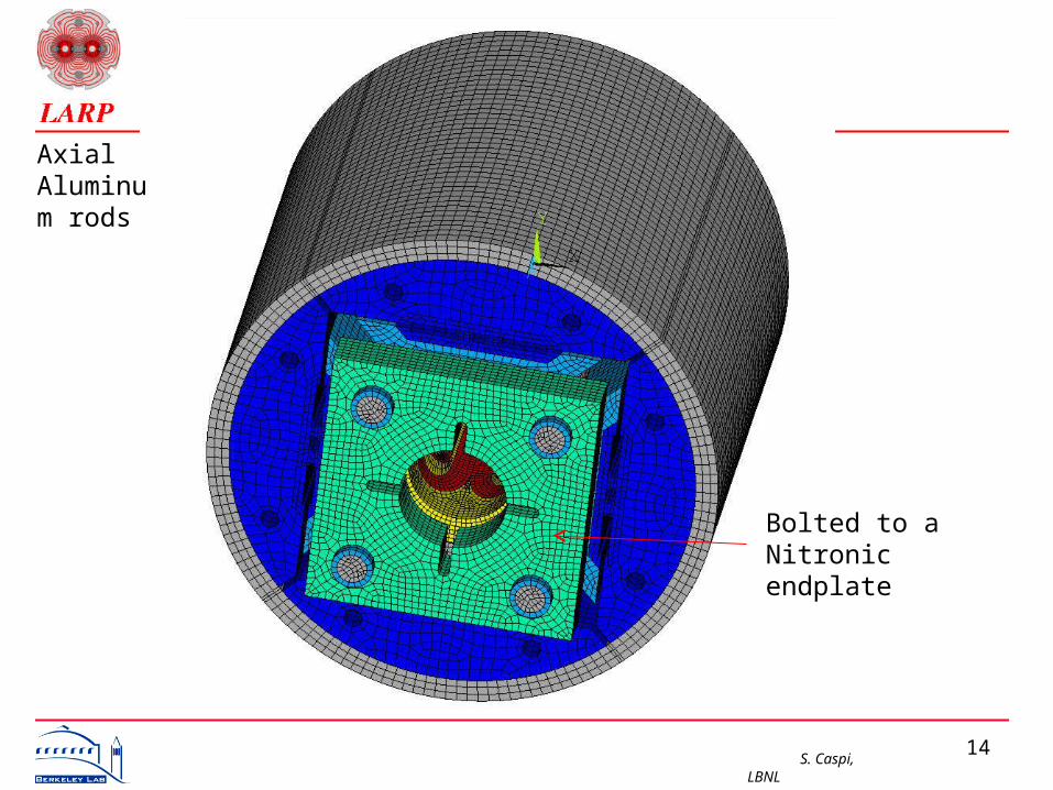
Reaction tooling
25

S. Caspi, LBNL
HQ Schedule (updated 9/18/08)
26
ID Task Name
1 Coil Design2 Cable design & test winding3 Coil design4 Tooling, Parts, Practice Coils5 Winding/Curing Tooling Design6 Winding/Curing Tooling Procure7 Coil parts design8 Coil parts procurement9 Practice winding #110 Practice winding #211 Reaction/potting tooling design12 Reaction/potting tooling procure13 Practice reaction/potting #114 Practice reaction/potting #215 Structure Design and Fabrication 16 Mechanical Design Concept17 Mechanical Analysis18 Engineering Design19 Structure Procurement20 Mechanical model21 HQ01 Model22 Cable and coil parts23 Coil Wind / Cure24 Coil React25 Coil Impreg26 Magnet Assembly27 Test28 Analysis & Reporting29 Review 12/7
Nov Dec Jan Feb Mar Apr May Jun Jul Aug Sep Oct Nov Dec Jan Feb Mar Apr May Jun Jul Aug Sep Oct Nov Dec JanQ1 '08 Q2 '08 Q3 '08 Q4 '08 Q1 '09 Q2 '09 Q3 '09 Q4 '09 Q1 '10 Q2 '10

S. Caspi, LBNL 27
Summary
• We have 90m of cable to wind first practice coil
• Design of coils, spacers, end-shoes, layer-to-layer transition completed.
• Shipment of tooling for winding and curing in the next few weeks
• Reaction and potting tooling in final design stage.
• 3D magnetic design completed.
• 3D analysis of structure and assembly underway.