ROPE RESCUE TECHNICIAN
178
ROPE RESCUE TECHNICIAN INSTRUCTOR and STUDENT GUIDE January 2015
-
Upload
nguyennhan -
Category
Documents
-
view
258 -
download
8
Transcript of ROPE RESCUE TECHNICIAN
ROPE RESCUE TECHNICIAN
INSTRUCTOR and STUDENT
GUIDE
January 2015


ROPE RESCUE TECHNICIAN
January 2015 Edition
Rope Rescue Technician
Instructor and Student Guide

ROPE RESCUE TECHNICIAN
January 2015 Edition
THIS PAGE BLANK
ROPE RESCUE TECHNICIAN
January 2015 Edition
ACKNOWLEDGEMENTS
Ken Pimlott Director, Cal Fire
Mark Ghilarducci
Secretary, Cal OES
Tonya Hoover State Fire Marshal
Kim Zagaris
Fire Chief, Cal OES Special Operations
Mike Richwine Chief, State Fire Training
Lorenzo Gigliotti
Deputy Chief, Cal OES Special Operations
Joe Gear Assistant Chief, Cal OES Special Operations
Ronny J. Coleman STEAC Chairperson
Rodney Slaughter
Deputy State Fire Marshal
Patrick Bell California Division of Occupational Safety and Heath
Sherri Martucci
California Fire and Rescue Training Authority
Cristy Jorgensen California Fire and Rescue Training Authority
Nicole Paskey
California Fire and Rescue Training Authority
ROPE RESCUE TECHNICIAN
January 2015 Edition
COURSE REFERENCES
California State Fire Training Low Angle Rope Rescue Operational Training Manual
California State Fire Training
Rescue Systems 1 Training Manual
NFPA 1006 Standard for
Technical Rescuer Professional Qualifications 2013 Edition
NFPA 1500 Standard on
Fire Department Occupational Safety and Health Program 2013 Edition
NFPA 1670 Standard on
Operations and Training for Technical Search and Rescue Incidents 2009 Edition
NFPA1983 Standard on
Life Safety Rope and Equipment for Emergency Services 2012 Edition
FIRESCOPE Urban Search and Rescue Operational System Description ICS-US&R-120-1
California Division of Occupational Safety and Heath
California Code of Regulations Title 8, Subchapter 7. General Industry Safety Orders Group 1. General Physical Conditions and Structures Article 4. Access, Work Space, and Work Areas
3270.1 Use of Rope Access Equipment
ROPE RESCUE TECHNICIAN
January 2015 Edition
We wish to acknowledge and thank the members of the following committees. Without their hard work and dedication, this course would not be possible.
Low Angle Rope Rescue Operational Curriculum Development Committee
Rescue Systems 1 Curriculum Development Committee
Peer Review Committee
Rope Rescue Technician Curriculum Development Committee Members:
Ernie Ojeda (Committee Chairperson)/ Los Angeles FD
Mark Cameron / Cal Fire, San Luis Obispo Unit
Wayne Chapman / Orange County Fire Authority
Frank Godinez / Chula Vista FD
Don Kelley / Sacramento FD
John McKently / CMC Rescue
Don Reyes / Los Angeles FD
This curriculum development committee would also like to give special thanks to the late Patrick Bell of the California Division of Occupational Safety and Health for his longtime support of the California fire service and especially for his help with the development of this manual.
ROPE RESCUE TECHNICIAN
January 2015 Edition
PREFACE
The Rope Rescue Technician curriculum provides required training as outlined in the FIRESCOPE Urban Search and Rescue Operational System Description ICS-US&R-120-1 to the Heavy Operational Level and nationally recognized standards such as NFPA 1006 and 1670.
This curriculum prepares the student for:
Man-made incidents
Weapons of mass destruction (WMD) Terrorist actions Chemical, Biological, Radiological, Nuclear, Explosives (CBRNE)
Natural disasters
Earthquakes Floods Other catastrophes
Throughout the presentation guide, instructors and students will realize that there may be more than one way to rig complex rope rescue systems. It is acceptable to rig systems differently than portrayed in the presentation guide as long as functional equivalence is maintained.
Functional equivalence shall be defined as equipment and/or techniques that are conceptually the same as portrayed in the presentation guide yet may have minor changes in rigging details. Functional equivalence entails maintaining concepts such as a two rope system, human haul teams (versus mechanical winches), redundancy at appropriate points, and an acceptable level of safety. Minor rigging changes might include removing unused parts of an RPM system, replacing tandem prussiks with mechanical devices (e.g. “540” or “MPD”), or using various types of load releasing hitches.
NFPA 1983 (2012) Annex 3.3.35, states that “an organization at the operational level performing simple rescues might require the higher margin of safety offered by general use equipment” while a “highly trained or specialized organization performing the more complicated rescue might benefit from the lighter weight of technical equipment [and] due to their higher level of training, can maintain an acceptable level of safety and efficiency for the specified operation.”
One of the most important aspects of the technician’s job is to analyze the comparative advantages and disadvantages of system changes. At the Rope Rescue Technician level,

ROPE RESCUE TECHNICIAN
January 2015 Edition
there are acceptable trade-offs and there is no single best way to rig a system. As stated above, “maintain an acceptable level of safety and efficiency for the specified operation.”
In the true sense of having redundant systems, each item in a system must be backed up- starting at the anchor continuing to the load. This is strived for when creating two-line systems. There may be times when it is not possible or practical to construct a perfectly redundant system. The rigger operating at the “Technician” level must be able to identify potential single point(s) of attachment, analyze any issues, and determine whether or not the single point of attachment is acceptable. For example, if an anchor is “bombproof” (i.e. freeway concrete column) and the rigger believes that it is prudent to use it to attach both the main and belay lines, then that anchor is truly a single point of potential failure. The rigger in this example has identified the anchor as a single point of attachment, analyzed any issues, and made the decision based upon knowledge, training and experience to use the single point of attachment. The critical analysis of each component is based on the minimum breaking strength of the item, its position in the system, any anticipated force multipliers, and the load itself. All this information will be compared to the acceptable safety margins the Authority Having Jurisdiction has in place.

ROPE RESCUE TECHNICIAN
January 2015 Edition
ROPE RESCUE TECHNICIAN
January 2015 Edition
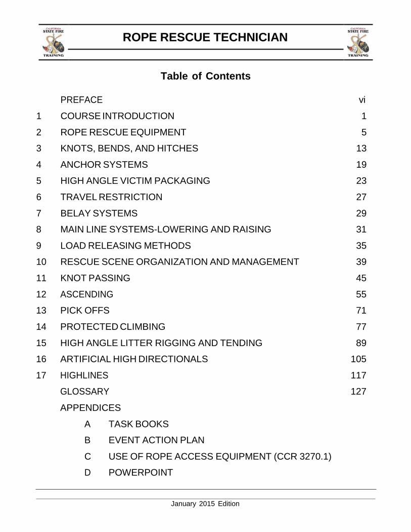
Table of Contents
PREFACE vi
1 COURSE INTRODUCTION 1
2 ROPE RESCUE EQUIPMENT 5
3 KNOTS, BENDS, AND HITCHES 13
4 ANCHOR SYSTEMS 19
5 HIGH ANGLE VICTIM PACKAGING 23
6 TRAVEL RESTRICTION 27
7 BELAY SYSTEMS 29
8 MAIN LINE SYSTEMS-LOWERING AND RAISING 31
9 LOAD RELEASING METHODS 35
10 RESCUE SCENE ORGANIZATION AND MANAGEMENT 39
11 KNOT PASSING 45
12 ASCENDING 55
13 PICK OFFS 71
14 PROTECTED CLIMBING 77
15 HIGH ANGLE LITTER RIGGING AND TENDING 89
16 ARTIFICIAL HIGH DIRECTIONALS 105
17 HIGHLINES 117
GLOSSARY 127
APPENDICES
A TASK BOOKS
B EVENT ACTION PLAN
C USE OF ROPE ACCESS EQUIPMENT (CCR 3270.1)
D POWERPOINT
ROPE RESCUE TECHNICIAN
January 2015 Edition
1
CHAPTER 1: COURSE INTRODUCTION
TERMINAL LEARNING OBJECTIVE
The student will be able to identify the course goals, planned activities to achieve those goals, and the requirements for successfully completing the Rope Rescue Technician course.
ENABLING LEARNING OBJECTIVES
1. Describe the course, including course objectives, syllabus, and calendar of events. 2. Demonstrate rescuer and victim safety during all Rope Rescue Technician exercises. 3. Select and use all personal protective equipment. 4. Describe the student evaluation process.
COURSE OBJECTIVES
The student will:
Understand regulations and standards for high angle rope rescue
Identify the hazards associated with high angle rope rescue
Demonstrate the ability to plan, organize, operate, and command at high angle rope rescue incidents
Demonstrate the ability to select and use rope rescue equipment necessary in high angle rope rescue
Identify, select, and use appropriate personal protective equipment
Demonstrate the use of various types of victim removal and packaging systems
Participate and be evaluated in high angle rope rescue scenarios
COURSE OVERVIEW
This five-day course is designed to meet or exceed certification requirements for Rope Rescue Technician (RRT) based on the current editions of NFPA 1670 (2009) and NFPA 1006 (2013). The minimum requirements found in these documents may change. If the minimum requirements change, the minimum requirements for this course will change accordingly. Upon completion of this course, the student will have demonstrated competence in all the Job Performance Requirements associated with Rope Rescue Technician.
SAFETY
Performing work while suspended by ropes has the potential for injury and even death. All SOG’s, SOP’s, Department Practices and Procedures, etc. must be adhered to while training or performing rope rescue work. In California, the California Code of Regulations (CCR)
Use of Rope Access Equipment is the standard. This section of the CCR establishes
ROPE RESCUE TECHNICIAN
January 2015 Edition
2
safety requirements for rope access. While training for rope rescues, this section is applicable and must be read and understood before attempting any training for rope rescue. However, under the section (a) “Scope and Application,” emergency search and rescue operations are specifically named as exempt.
SYSTEM SAFETY CHECKS
Safety is the most important aspect of our job. While training or executing an actual rope rescue, the safety of our personnel and the patient is paramount. During rigging, check each piece of equipment as it is placed into the system. If anything is suspect, pull it out and replace it. Prior to placing a live load on the system, perform a safety check on all equipment from the anchor to the harness.
A proper system safety check consists of physically checking the system to ensure proper rigging, performing a load test prior to life-loading the system, and verbally confirming these actions. The verbal confirmation must be announced and acknowledged.
LOCK OUT TAG OUT
Lock Out Tag Out (LOTO) is the safety procedure which ensures that a potential energy source is rendered safe and inoperative. The source is secured, normally with a lock of some sort, and then an identifying tag is placed on it to warn others of the status of that piece of equipment. The need for LOTO arises in a rope rescue evolution whenever a system component, team member, or victim may come in contact with a potential energy source.
Two examples of when there is a need for LOTO:
An apparatus being used as an anchor. A tower rescue with live electrical wires.
STATIC SYSTEM SAFETY FACTOR
A rope system contains many parts, and each part has a minimum breaking strength. Find the weakest “link” in the system and ratio that to the known or anticipated load. This number is known as the Static System Safety Factor. For example, if the weakest component in a system has a minimum breaking strength of 600lbf and the load exerts 600lbf, then the Safety Factor would be 1:1. This would not be an acceptable Safety Factor since theoretically at 601lbf the system would break (and the load would fall). Some rescue teams concerned with weight of their gear use the lightest pieces possible. Subsequently, components found in their systems have a lower minimum breaking strength. Their acceptable System Safety Factors may be 4:1 or 5:1. Other rescue teams may be less concerned with the weight of their equipment and can therefore have a higher System Safety Factor, for example 10:1. In either case, before a live load is placed, every rope system must be analyzed and must meet or exceed the AHJ’s predetermined System Safety Factor.
ROPE RESCUE TECHNICIAN
January 2015 Edition
3
PERSONAL PROTECTIVE EQUIPMENT
Personal Protective Equipment (PPE). The equipment provided to shield or isolate a person from the chemical, physical, or thermal hazards that can be encountered at a specific rescue incident. PPE can include: helmet, gloves, long sleeve shirt, long sleeve pants, leather boots, eye protection, ear protection, and a life safety harness.
STUDENT TASK BOOK
The RRT student task book is designed to accompany this course and serve as a tracking method for completion of all Job Performance Requirements, skills, and evolutions. The evaluating instructor will sign the task book. The student will keep the task book for their own personal records.

ROPE RESCUE TECHNICIAN
4
THIS PAGE BLANK
January 2015 Edition
ROPE RESCUE TECHNICIAN
January 2015 Edition
5
CHAPTER 2: ROPE RESCUE EQUIPMENT
TERMINAL LEARNING OBJECTIVE
The student will demonstrate the proper use of the equipment used in the Rope Rescue
Technician course.
ENABLING LEARNING OBJECTIVES
1. Describe the use/misuse of the rope rescue equipment.
2. Describe the inspection/maintenance of the rope rescue equipment.
3. Use, inspect, and maintain all rope rescue equipment.
ROPE RESCUE EQUIPMENT
Each piece of rope rescue equipment has the potential to hold someone’s life. Rope rescue
equipment shall be used, cared for, inspected, and maintained per the manufacturer’s
guidelines. NFPA and the CCR set forth expectations for equipment inspection and
maintenance and a Rope Rescue Technician is expected to be able to do the following:
Inspect and maintain rescue equipment.
Perform pre-service and post-service inspection procedures.
Keep maintenance records.
Place items subject to replacement out of service per the manufacturer’s guidelines.
ROPE RESCUE TECHNICIAN
January 2015 Edition
6
NEW EQUIPMENT
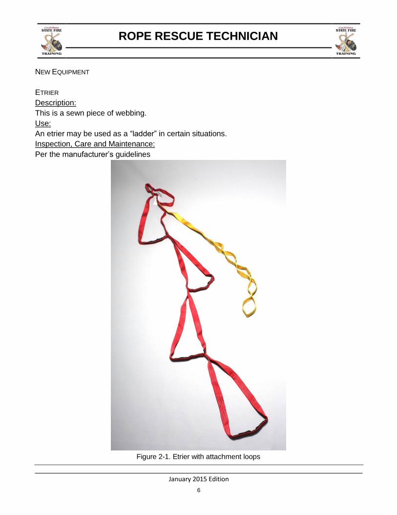
ETRIER
Description:
This is a sewn piece of webbing.
Use:
An etrier may be used as a “ladder” in certain situations.
Inspection, Care and Maintenance:
Per the manufacturer’s guidelines
Figure 2-1. Etrier with attachment loops
ROPE RESCUE TECHNICIAN
January 2015 Edition
7
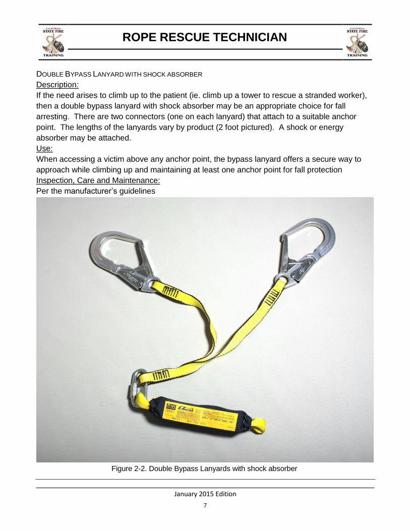
DOUBLE BYPASS LANYARD WITH SHOCK ABSORBER
Description:
If the need arises to climb up to the patient (ie. climb up a tower to rescue a stranded worker),
then a double bypass lanyard with shock absorber may be an appropriate choice for fall
arresting. There are two connectors (one on each lanyard) that attach to a suitable anchor
point. The lengths of the lanyards vary by product (2 foot pictured). A shock or energy
absorber may be attached.
Use:
When accessing a victim above any anchor point, the bypass lanyard offers a secure way to
approach while climbing up and maintaining at least one anchor point for fall protection
Inspection, Care and Maintenance:
Per the manufacturer’s guidelines
Figure 2-2. Double Bypass Lanyards with shock absorber

ROPE RESCUE TECHNICIAN
January 2015 Edition
8
MINI MECHANICAL ADVANTAGE SYSTEM
Description:
A typical setup may include 50’ of 8mm accessory cord running through two double sheave
pulleys.
Use:
Any time the need arises for mechanical advantage.
Inspection, Care, and Maintenance:
Per the manufacturer’s guidelines
Figure 2-3. Mini Mechanical Advantage

ROPE RESCUE TECHNICIAN
January 2015 Edition
9
SWIVELS
Description:
Two rated connection points attached in-line with one another that possess the ability to rotate
upon that axis.
Use:
Any time the need arises to remove twist out of a rope system
Inspection, Care, and Maintenance;
Per the manufacturer’s guidelines
Figure 2-4. Swivels (NFPA “G” Rated and “T” Rated)
ROPE RESCUE TECHNICIAN
January 2015 Edition
10
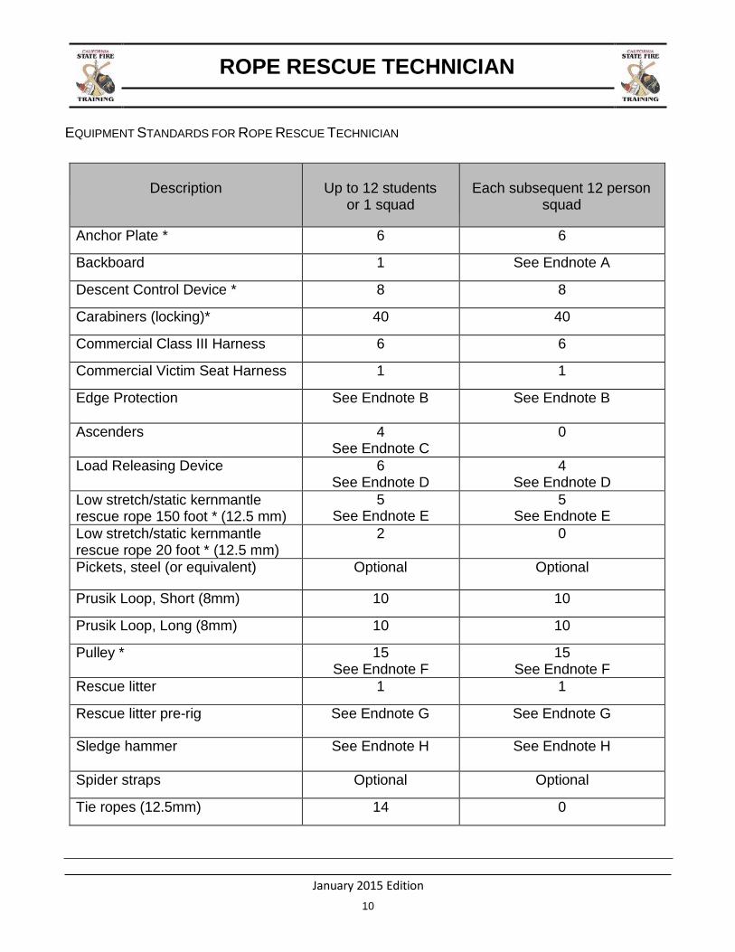
EQUIPMENT STANDARDS FOR ROPE RESCUE TECHNICIAN
Description
Up to 12 students or 1 squad
Each subsequent 12 person squad
Anchor Plate * 6 6
Backboard 1 See Endnote A
Descent Control Device * 8 8
Carabiners (locking)* 40 40
Commercial Class III Harness 6 6
Commercial Victim Seat Harness 1 1
Edge Protection See Endnote B See Endnote B
Ascenders 4 See Endnote C
0
Load Releasing Device 6 See Endnote D
4 See Endnote D
Low stretch/static kernmantle rescue rope 150 foot * (12.5 mm)
5 See Endnote E
5 See Endnote E
Low stretch/static kernmantle rescue rope 20 foot * (12.5 mm)
2 0
Pickets, steel (or equivalent) Optional Optional
Prusik Loop, Short (8mm) 10 10
Prusik Loop, Long (8mm) 10 10
Pulley * 15 See Endnote F
15 See Endnote F
Rescue litter 1 1
Rescue litter pre-rig See Endnote G See Endnote G
Sledge hammer See Endnote H See Endnote H
Spider straps Optional Optional
Tie ropes (12.5mm) 14 0
January 2015 Edition
11
ROPE RESCUE TECHNICIAN
Description
Up to 12 students or 1 squad
Each subsequent 12 person squad
Webbing, green * 1” x 5’ 12 12
Webbing, yellow * 1” x 12’ 12 12
Webbing, blue * 1” x 15’ 12 12
Webbing, orange * 1” x 20’ 12 12
Knot passing pulley * 1 0
Pick off strap * 2 0
Etriers 2 See Endnote I
0
Double bypass lanyard Optional Optional
Mini MA system See Endnote J See Endnote J
Artificial High Directional See Endnote K See Endnote K
Swivels * Optional See Endnote L
Optional See Endnote L
Equipment to Belay a Falling Load
See Endnote M 0
ENDNOTES
* Indicates must meet NFP A 1 9 8 3 “G ” ra ting
A. 1 backboard per site.
B. Edge protection can be manufactured (rope rollers, etc) or improvised (split fire hose, etc).
There shall be adequate amounts of edge protection available for concurrent running
scenarios.
C. While Gibbs Ascenders™ are acceptable, handled ascenders are preferred.
D. Commercial or field assembled (with webbing or cordelette) complete with General Use
carabiners. These carabiners are in addition to the amounts specified under the carabiner and
prusik categories.

January 2015 Edition
12
ROPE RESCUE TECHNICIAN
E. Each rope of the two-track highline must be one continuous length of rope. If your highline
span is greater than 150 feet you must acquire longer ropes to span the gap. You may also
need a longer reeve line rope.
F. 5 of the 15 pulleys must be single sheave prusik minding. 2 of the 15 should be double
sheave prusik minding. Subsequent squads may not require additional double sheave pulleys.
G. Commercial or field assembled complete with General Use carabiners and prusiks, if field
assembled these carabiners and prusiks are in addition to the amounts specified under the
carabiner and prusik categories.
H. If pickets are used a sledge hammer is required.
I. Can be commercial or field assembled from one inch tubular webbing.
J. If performing the optional litter scoop evolution, a mini MA system will be needed to lower
and raise the foot end of the litter. Can be commercial or improvised.
K. Can be a commercial (Arizona Vortex™, Terradaptor™) or improvised high directional (4x4
lumber). If concurrent highline stations are being run, one additional artificial high directional
per highline must be provided.
L. “G” rated pulleys that have a built in swivel will satisfy this requirement.
M. This can be accomplished by having a person perform a hard, unexpected jerk on the belay
system.
ADDITIONAL NOTES
1. Instructors at “Agency Specific” classes that use the CMC MPD™, Traverse 540 Rescue
Belay™, and other similar devices may use these devices during the class.
2. Instructors at “open enrollment” classes should continue to show “traditional” methods of
lowering & raising to their students (i.e RPM). This does not mean that devices like the
CMC MPD™, Traverse 540 Rescue Belay™, and other similar devices cannot be shown
to students.
January 2015 Edition
13
ROPE RESCUE TECHNICIAN
CHAPTER 3: KNOTS, BENDS, AND HITCHES
TERMINAL LEARNING OBJECTIVE
The student will identify and properly tie knots, bends, and hitches.
ENABLING LEARNING OBJECTIVES
1. Tie a tensionless hitch. 2. Tie optional knots, bends, and hitches as required.
GENERAL
Knots, bends, and hitches can be categorized in the following 5 ways:
1. End-of-line loop: figure 8 on a bight, figure 8 follow through.
2. Midline loop: *alpine butterfly, *longtail bowline.
3. Securing rope around desired objects: clove hitch, round turn and two half hitches
*tensionless hitch, *Munter hitch.
4. Joining rope or webbing together: figure 8 bend, overhand bend, double overhand bend.
5. Gripping rope: three wrap prusik hitch.
*denotes newly introduced knots.
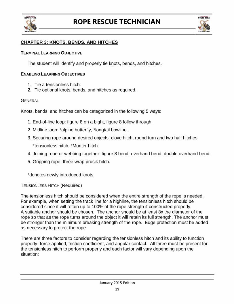
TENSIONLESS HITCH (Required)
The tensionless hitch should be considered when the entire strength of the rope is needed. For example, when setting the track line for a highline, the tensionless hitch should be considered since it will retain up to 100% of the rope strength if constructed properly. A suitable anchor should be chosen. The anchor should be at least 8x the diameter of the rope so that as the rope turns around the object it will retain its full strength. The anchor must be stronger than the minimum breaking strength of the rope. Edge protection must be added as necessary to protect the rope.
There are three factors to consider regarding the tensionless hitch and its ability to function properly- force applied, friction coefficient, and angular contact. All three must be present for the tensionless hitch to perform properly and each factor will vary depending upon the situation:
January 2015 Edition
14
ROPE RESCUE TECHNICIAN
Force applied- as with all other hitches, if the force applied is released, the hitch will begin to lose contact with the object it is wrapped around and could potentially fall apart. The more force applied to the tensionless hitch, the better it will grasp.
Friction coefficient- this term refers to how “sticky” the surface of an object is. Tree bark from an oak tree is likely to have a higher friction coefficient than the surface of a structural pole.
Angular contact – one complete wrap of an anchor is considered to be 360 degrees. The more wraps of the anchor results in more degrees of contact. Four wraps (1,440 degrees) is a good place to begin when considering how many wraps are necessary.
The tensionless hitch is completed when it is tied off upon the working line with either a figure 8 follow through or a figure 8 on a bight connected with a carabiner.
Figure 3-1. Tensionless Hitch
January 2015 Edition
15
ROPE RESCUE TECHNICIAN
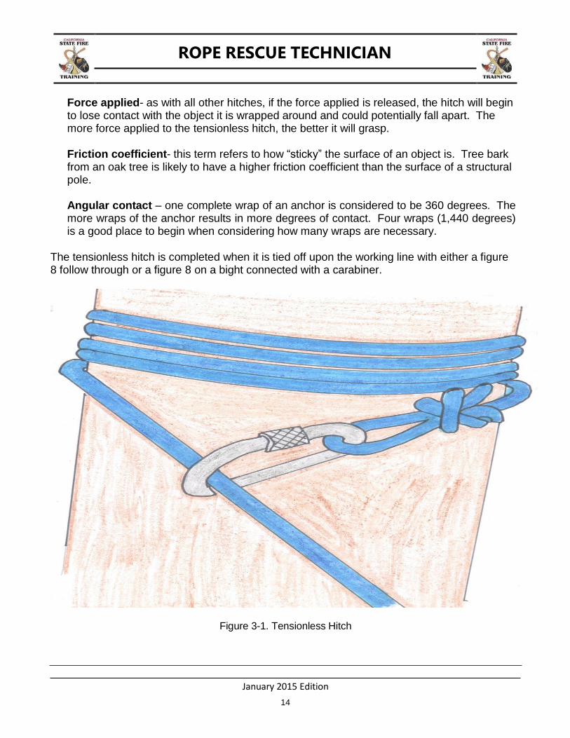
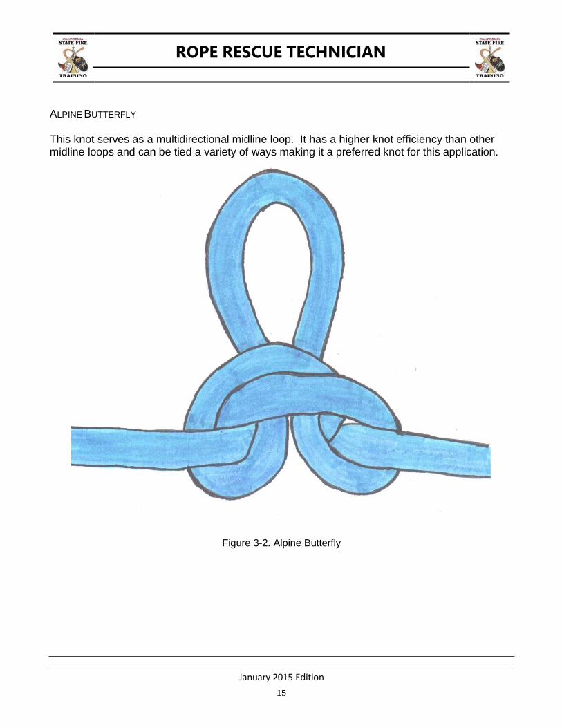
ALPINE BUTTERFLY
This knot serves as a multidirectional midline loop. It has a higher knot efficiency than other midline loops and can be tied a variety of ways making it a preferred knot for this application.
Figure 3-2. Alpine Butterfly
January 2015 Edition
16
ROPE RESCUE TECHNICIAN
Figure 3-3a. Tying the Alpine Butterfly, Step 1
Figure 3-3b. Tying the Alpine Butterfly, Step 2
Figure 3-3c. Tying the Alpine Butterfly, Step 3
January 2015 Edition
17
ROPE RESCUE TECHNICIAN
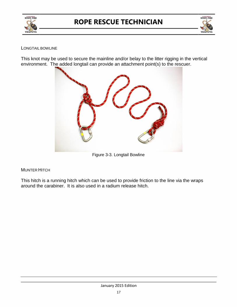
LONGTAIL BOWLINE
This knot may be used to secure the mainline and/or belay to the litter rigging in the vertical environment. The added longtail can provide an attachment point(s) to the rescuer.
Figure 3-3. Longtail Bowline
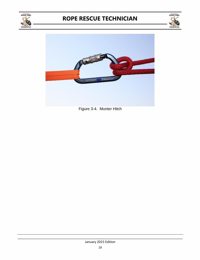
MUNTER HITCH
This hitch is a running hitch which can be used to provide friction to the line via the wraps around the carabiner. It is also used in a radium release hitch.
January 2015 Edition
18
ROPE RESCUE TECHNICIAN
Figure 3-4. Munter Hitch
January 2015 Edition
19
ROPE RESCUE TECHNICIAN
CHAPTER 4: ANCHOR SYSTEMS
TERMINAL LEARNING OBJECTIVE
The student will demonstrate anchor selection and anchor system construction.
ENABLING LEARNING OBJECTIVES
1. Describe system safety factors, critical angles, and force multipliers. 2. Describe considerations when selecting anchors. 3. Describe the types of anchors. 4. Construct the required anchor systems.
ANCHORS
An anchor is a component used either alone or in combination with other anchor points to create an anchor system capable of sustaining the potential load. Anchors can be man-made, (i.e. an apparatus or guardrail piling) or natural such as a boulder or tree. Ideally the anchor should be bombproof. A bombproof anchor is a term used to describe an anchor capable of sustaining the potential forces exerted on the rope rescue system without the possibility of failure.
SINGLE POINT ANCHOR
A single point anchor is an anchor that relies on a single point to support the entire load. A properly constructed single-point anchor will meet the following criteria:
The strength of the anchor should meet or exceed the potential forces and its location should not interfere with rescue operations.
The anchor inspection and loading is critical, prior to being placed into service.
If a potential anchor cannot support the load, select another, or construct an anchor system that will support the load.
MULTI POINT ANCHOR SYSTEM
A multi-point anchor system is two or more anchors rigged to provide a connection point capable of sustaining the potential load.
A properly constructed multi-point anchor system will consist of the following criteria:
The anchor system should meet or exceed the potential forces and not interfere with rescue operations.
Prior to being placed into service, it is critical that the anchor system be inspected and test loaded.
The load will be distributed between more than one anchor point.

January 2015 Edition
20
ROPE RESCUE TECHNICIAN
Multi point anchor systems are predominately constructed in two ways: load distributing and load sharing. When utilizing a multi point anchor system, avoid exceeding the critical angle.
CRITICAL ANGLE
The critical angle is an internal angle in a system of 120 degrees or greater that results in an amplification of a force applied to the system. The angle which results from wrapping a multi point anchor system must be noticed and calculated. At 120 degrees, the load carried is equal to what is being placed upon the two anchors. When the angle is greater than 120 degrees, the load placed upon the two anchors will exceed the load being carried. Conversely, when the angle is less than 120 degrees, the two anchors each carry less than the load.
Figure 4-1. Two examples of 120 Degree Critical Angle
90 degrees keeps the load on a multi-point anchor less than a single point anchor would encounter (approximately .7x the load on each anchor). Even in a single point anchor the internal angle should be 90 degrees or less. 90 degrees is an easy angle to determine in the field and it will make it easier on the anchor(s).
When the internal angle is 120 degrees or greater the load on each anchor is greater than it would be on a single point anchor, thus creating a force multiplier.
January 2015 Edition
21
ROPE RESCUE TECHNICIAN
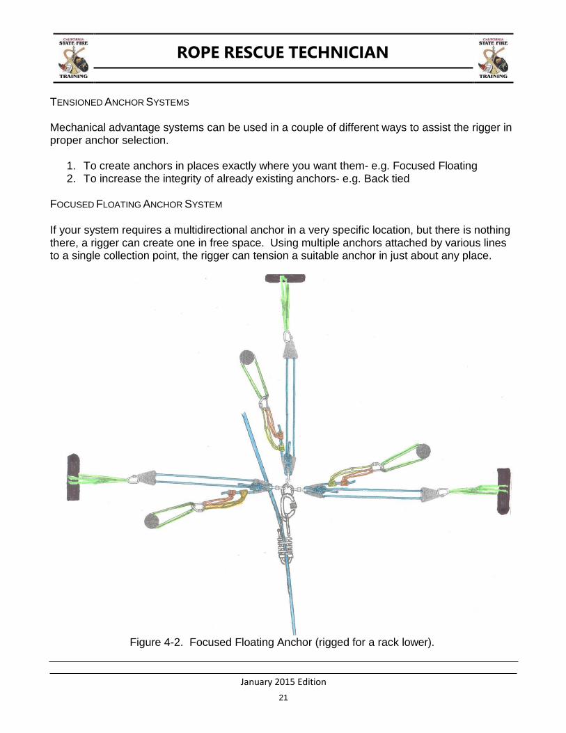
TENSIONED ANCHOR SYSTEMS
Mechanical advantage systems can be used in a couple of different ways to assist the rigger in proper anchor selection.
1. To create anchors in places exactly where you want them- e.g. Focused Floating 2. To increase the integrity of already existing anchors- e.g. Back tied
FOCUSED FLOATING ANCHOR SYSTEM
If your system requires a multidirectional anchor in a very specific location, but there is nothing there, a rigger can create one in free space. Using multiple anchors attached by various lines to a single collection point, the rigger can tension a suitable anchor in just about any place.
Figure 4-2. Focused Floating Anchor (rigged for a rack lower).
January 2015 Edition
22
ROPE RESCUE TECHNICIAN
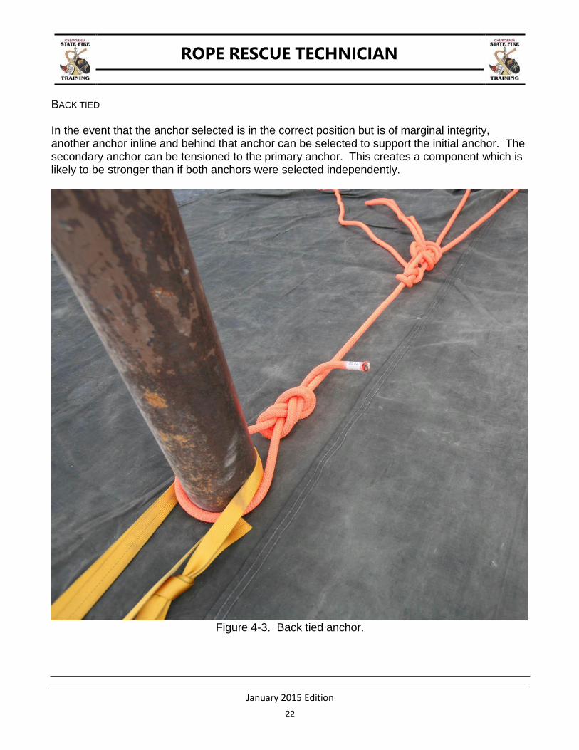
BACK TIED
In the event that the anchor selected is in the correct position but is of marginal integrity, another anchor inline and behind that anchor can be selected to support the initial anchor. The secondary anchor can be tensioned to the primary anchor. This creates a component which is likely to be stronger than if both anchors were selected independently.
Figure 4-3. Back tied anchor.

January 2015 Edition
23
ROPE RESCUE TECHNICIAN
CHAPTER 5: HIGH ANGLE VICTIM PACKAGING
TERMINAL LEARNING OBJECTIVE
The student will package a victim in a high angle environment.
ENABLING LEARNING OBJECTIVES
1. Package an ambulatory victim in a commercial victim harness. 2. Package an ambulatory victim in an improvised webbing harness. 3. Package a non-ambulatory victim in a rescue litter.
Proper packaging of victims is essential for a safe rope rescue operation. Rescuers must have
the knowledge, skill, and ability to assess the level of injury, select the most appropriate means
for packaging, and effectively secure it on a victim in the high angle environment.
When training at heights above two feet in the vertical or free space environment, the “victim”
must be wearing an NFPA Class III harness with the appropriate level of protection from falls.
The “rescuer” may place an NFPA Class II Victim Extrication Device (or improvised harness)
over the NFPA Class III harness to allow “rescuers” to practice less than optimal methods of
packaging while remaining safe in the training environment.
COMMERCIAL VICTIM PELVIC HARNESS
There are a variety of commercially manufactured victim pelvic harnesses on the market. All
models attach quickly and securely around the waist and thighs or under buttocks, no matter
where or how the victim is positioned. The design allows the harness to be put on without the
victim having to step into the harness. This is particularly helpful if the person is only
supported by their hands and feet.
When faced with the practical complications in the high angle rescue environment, the rope
rescue technician may need to take quick actions to secure and package a victim. While the
optimal victim harness would be an NFPA Class III Victim Extrication Device, less optimal
methods may be required. The use of an NFPA Class II Victim Extrication Device is a common
and appropriate selection in most instances.
The donning, use, care, and maintenance should be performed according to the
manufacturer’s instructions, but the general method follows. Practice with this method should
allow you to modify the steps to meet unusual situations.

January 2015 Edition
24
ROPE RESCUE TECHNICIAN
1. Open the bag and completely remove the harness. Hold the waist buckle in one hand, and the waist V ring in the other hand.
2. Reach around and clip the waist V-Ring into its buckle. Center the waist loop to the victim's front and tighten the waist belt snugly.
3. Pull the leg loops down, between the legs, and to the outside of the victim's body. 4. Clip the V-Rings into the buckles of the matching color. Pull the ends to tighten so
the leg loops fit snugly. If you are concerned about the buckles slipping, tie an overhand knot in the end of all the straps.
5. Check the following: - The V-Rings are securely clipped into each buckle. - The harness is snug and not pinching or binding. - The buckles are not causing the victim any discomfort.
Figure 5-1. Commercial Victim Harness
When faced with the practical complications in the high angle rescue environment the rope rescue technician may need to take quick actions to secu re and package

January 2015 Edition
25
ROPE RESCUE TECHNICIAN
a victim. While the optimal victim harness would be an NFPA Class III Victim Extrication Device less optimal methods may be required. The use of an NFPA Class II Victim Extrication Device is a common and appropriate selection in most instances.
IMPROVISED VICTIM PELVIC AND CHEST HARNESSES
Improvised methods for capturing the victim such as webbing may be used in extreme
situations only. Due to the smaller surface area of contact with 1” webbing as compared to the
padding and webbing found on commercially made harnesses (often 1-3/4” or greater), it is not
advised to use 1” webbing on a person unless other clear and present risks outweigh the
damage which can be done. An improvised harness may also be used only after exhausting
all rescue-specific commercially made harnesses, as in the case of a multiple victim extraction.
When training with an improvised webbing harness ensure that the safety of the “victim” is
paramount and that the victim shall be at a maximum height (per Cal OSHA recommendation)
of two feet above grade.
When training at height more than two feet above grade the victim must be wearing
an NFPA Class III harness, the rescuer may place an NFPA Class II Victim
Extrication Device or improvised harness over the NFPA Class III harness to allow
rescuers to practice less than optimal methods in the training environment.
RESCUE LITTERS
Rescue litters serve several purposes during rope rescue operations. They provide victim
stabilization, protection, and a method for rescuers to easily manage the rescue load during
extrication. The rescue litter also provides a foundation to which ropes are attached for raising
and lowering a victim in a high angle environment. A litter can be either tended or unattended,
depending on factors such as necessity for patient care, difficult obstacles, or terrain.
The rescue litter by itself does not provide spinal immobilization. A victim requiring cervical
spine immobilization should first be properly secured to a backboard, in accordance with local
EMS policy, and then placed and secured inside the litter.
Rescue litters should be inspected regularly for bends, cracks, broken welds, and damage or
wear to any plastic. Cleaning can be performed with mild soap and water. Decontamination
can be accomplished as per department policies. All attachment options for the litter must be
in accordance with the manufacturer’s recommendations.
ROPE RESCUE TECHNICIAN
26
THIS PAGE BLANK
January 2015 Edition
ROPE RESCUE TECHNICIAN
January 2015 Edition
27
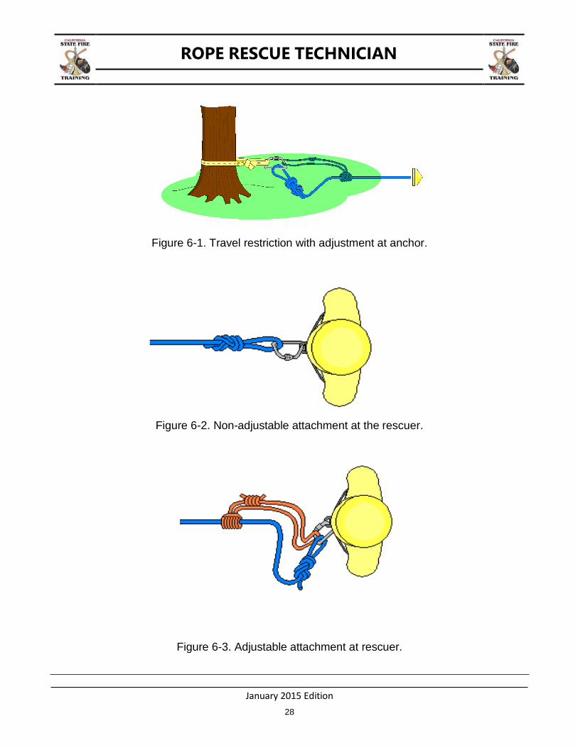
CHAPTER 6: TRAVEL RESTRICTION
TERMINAL LEARNING OBJECTIVE
The student will demonstrate the selection, construction, and use of travel restriction for rescuers.
ENABLING LEARNING OBJECTIVES
1. Construct a travel restriction system. 2. Attach a rescuer to a travel restriction system.
TRAVEL RESTRICTION
The purpose of a travel restriction system is to eliminate the possibility of a fall while still allowing the necessary degree of movement for rescuer(s) to perform their assignment. A travel restriction system shall be used any time a rescuer is within 6 feet of an unprotected edge (per Cal OSHA). The travel restriction system will consist of an anchor, approved harness, lifeline, and related hardware and software adjusted to limit travel.
The travel restriction system should be used when there is a possibility of a fall and rigged to allow the movement of rescuers only as far as the sides of the working level or working area.
COMPONENTS OF A TRAVEL RESTRICTION SYSTEM
An anchor that is capable of supporting at least twice the maximum anticipated dynamic
load.
An appropriate length of lifeline attached to the anchor and rescuer. One or both ends of the lifeline should be adjustable.
While a NFPA Class III harness is preferred, an NFPA Class II harness is acceptable for use in travel restriction.
HOW TO CONSTRUCT A TRAVEL RESTRICTION SYSTEM
Select an appropriate anchor.
Secure lifeline to anchor.
Secure lifeline to harness.
Place lifeline adjustment as needed.
ROPE RESCUE TECHNICIAN
January 2015 Edition
28
Figure 6-1. Travel restriction with adjustment at anchor.
Figure 6-2. Non-adjustable attachment at the rescuer.
Figure 6-3. Adjustable attachment at rescuer.

ROPE RESCUE TECHNICIAN
January 2015 Edition
29
CHAPTER 7: BELAY SYSTEMS
TERMINAL LEARNING OBJECTIVE
The student will demonstrate proper technique to belay a load in the event of a failure of the main line.
ENABLING LEARNING OBJECTIVES
1. Define key points regarding the operation of a belay. 2. Catch a load with a belay.
An important part of ensuring safety is the utilization of a belay line to catch the load in the event of a failure of the main line. The belay line is ideally attached to a separate anchor and exists independent of the main line. In the event of a mainline failure, the load will transfer to the belay.
KEY POINTS REGARDING THE OPERATION OF A BELAY SYSTEM
The entire operation is only as safe as the belay system and its operator.
Personnel operating the belay line must be competent. These skills are perishable and their maintenance requires regular hands-on practice under the supervision of a qualified person.
Minimize any slack in the belay system.
Keep thumbs from underneath the belay line.
The rescue package can only move as fast as the belayer can effectively move line through the system.
AHJ may choose to use other means for belay systems. Alternate belay systems must be functionally equivalent to the tandem prusik belay system.
ROPE RESCUE TECHNICIAN
January 2015 Edition
30
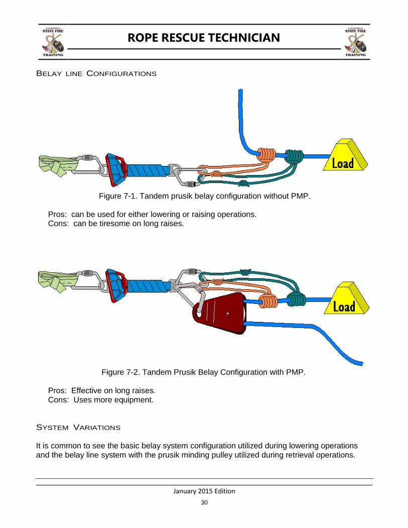
BELAY LINE CONFIGURATIONS
Figure 7-1. Tandem prusik belay configuration without PMP.
Pros: can be used for either lowering or raising operations. Cons: can be tiresome on long raises.
Figure 7-2. Tandem Prusik Belay Configuration with PMP.
Pros: Effective on long raises. Cons: Uses more equipment.
SYSTEM VARIATIONS
It is common to see the basic belay system configuration utilized during lowering operations and the belay line system with the prusik minding pulley utilized during retrieval operations.
ROPE RESCUE TECHNICIAN
January 2015 Edition
31
CHAPTER 8: MAIN LINE SYSTEMS-LOWERING AND RAISING
TERMINAL LEARNING OBJECTIVES
The student will demonstrate how to construct a lowering system and convert to a raising system using simple and compound mechanical advantage.
ENABLING LEARNING OBJECTIVES
1. Describe system safety factors, critical angles, and force multipliers. 2. Construct and operate a lowering system. 3. Convert a lowering system to a raising system using a compound 9:1. 4. Construct and operate a simple 5:1 “pig rig”.
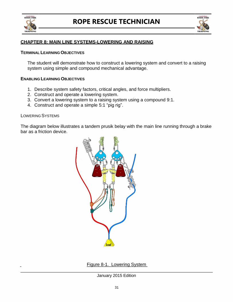
LOWERING SYSTEMS
The diagram below illustrates a tandem prusik belay with the main line running through a brake bar as a friction device.
Figure 8-1. Lowering System
ROPE RESCUE TECHNICIAN
January 2015 Edition
32
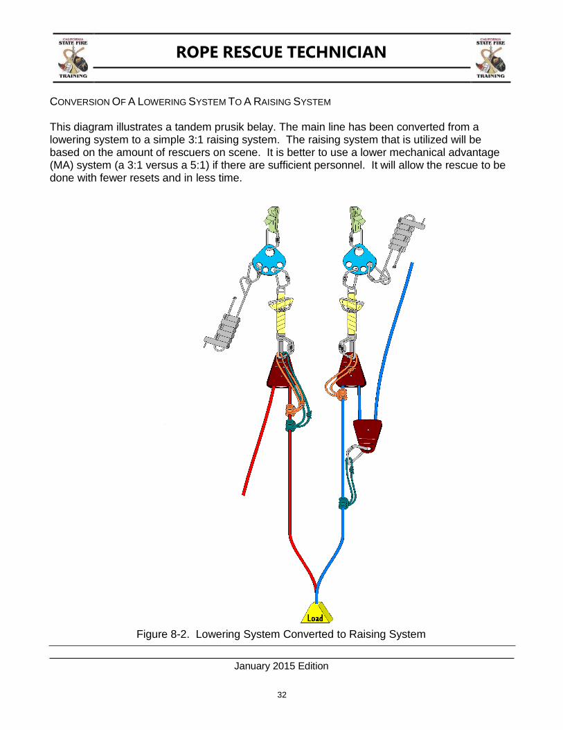
CONVERSION OF A LOWERING SYSTEM TO A RAISING SYSTEM
This diagram illustrates a tandem prusik belay. The main line has been converted from a lowering system to a simple 3:1 raising system. The raising system that is utilized will be based on the amount of rescuers on scene. It is better to use a lower mechanical advantage (MA) system (a 3:1 versus a 5:1) if there are sufficient personnel. It will allow the rescue to be done with fewer resets and in less time.
Figure 8-2. Lowering System Converted to Raising System
ROPE RESCUE TECHNICIAN
January 2015 Edition
33
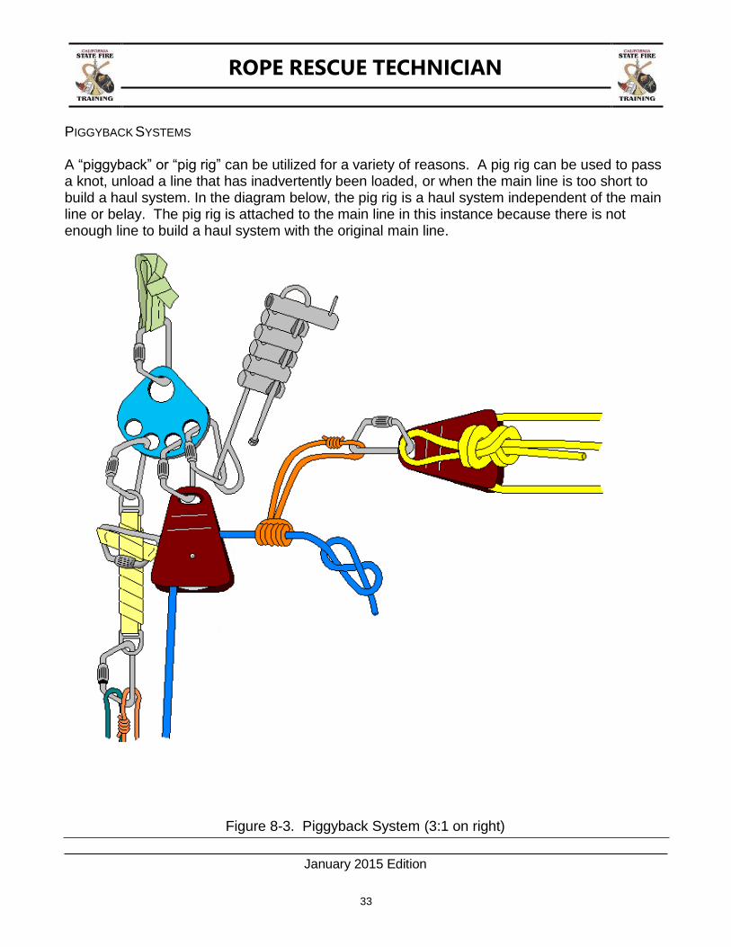
PIGGYBACK SYSTEMS
A “piggyback” or “pig rig” can be utilized for a variety of reasons. A pig rig can be used to pass a knot, unload a line that has inadvertently been loaded, or when the main line is too short to build a haul system. In the diagram below, the pig rig is a haul system independent of the main line or belay. The pig rig is attached to the main line in this instance because there is not enough line to build a haul system with the original main line.
Figure 8-3. Piggyback System (3:1 on right)

ROPE RESCUE TECHNICIAN
January 2015 Edition
34
COMPOUND MECHANICAL ADVANTAGE (MA)
A compound MA system is a simple system placed on a simple system. The illustration below is a compound 9:1 MA system. It is comprised of a simple 3:1, pulling on another simple 3:1 MA. To determine the total MA of a compound system, multiply the individual simple systems.
Figure 8-4. 9:1 Compound Mechanical advantage (3:1 X 3:1 = 9:1)
ROPE RESCUE TECHNICIAN
January 2015 Edition
35
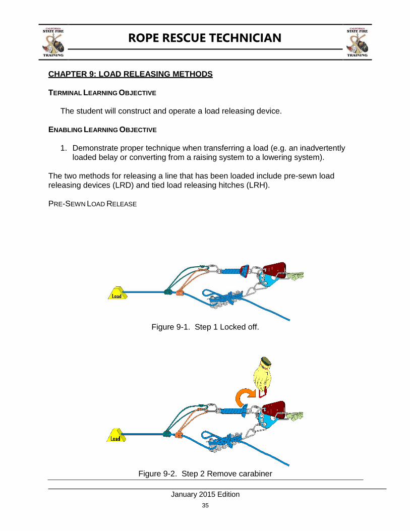
CHAPTER 9: LOAD RELEASING METHODS
TERMINAL LEARNING OBJECTIVE
The student will construct and operate a load releasing device.
ENABLING LEARNING OBJECTIVE
1. Demonstrate proper technique when transferring a load (e.g. an inadvertently
loaded belay or converting from a raising system to a lowering system).
The two methods for releasing a line that has been loaded include pre-sewn load releasing devices (LRD) and tied load releasing hitches (LRH).
PRE-SEWN LOAD RELEASE
Figure 9-1. Step 1 Locked off.
Figure 9-2. Step 2 Remove carabiner

ROPE RESCUE TECHNICIAN
January 2015 Edition
36
Figure 9-3. Step 3 Unlace strap.
Figure 9-4. Step 4 Slowly unwind strap.
Figure 9-5. Step 5 Slowly allow LRH to extend.

ROPE RESCUE TECHNICIAN
January 2015 Edition
37
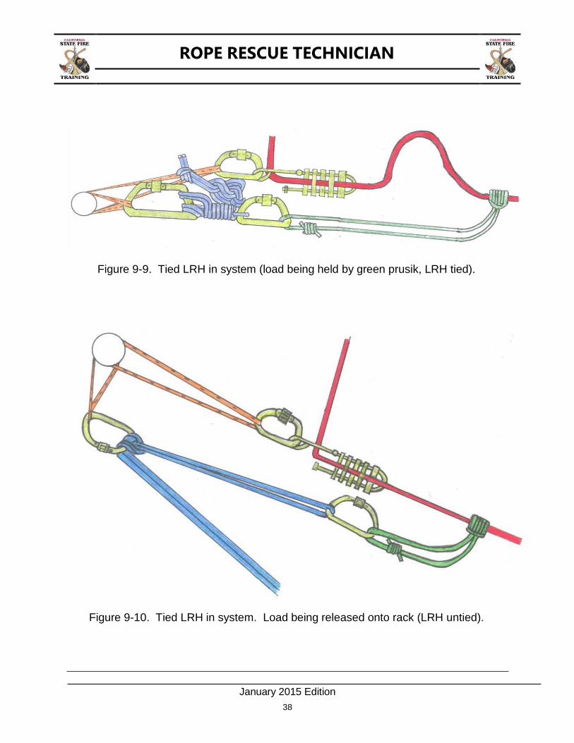
TIED LOAD RELEASE
The second method is using a tied load releasing hitch. The first three diagrams illustrate the hitch being untied and extended. The final two diagrams illustrate the hitch as it would be placed in a system.
FIGURE 9-6. Step 1 Tied off.
FIGURE 9-7. Step 2 Untying.
FIGURE 9-8. Step 3 Extending.
ROPE RESCUE TECHNICIAN
January 2015 Edition
38
Figure 9-9. Tied LRH in system (load being held by green prusik, LRH tied).
Figure 9-10. Tied LRH in system. Load being released onto rack (LRH untied).

ROPE RESCUE TECHNICIAN
January 2015 Edition
39
CHAPTER 10: RESCUE SCENE ORGANIZATION AND MANAGEMENT
TERMINAL LEARNING OBJECTIVE
The student will implement the Incident Command System (ICS).
ENABLING LEARNING OBJECTIVES
1. Size up a rescue incident. 2. Create objectives, strategy and tactics. 3. Give operational and safety briefings. 4. Implement rescue scene organization, management, assign positions. 5. Use command and control in rope rescue operations. 6. Terminate the incident.
Rescue Scene Organization And Management
FIRST ON SCENE
The first rescuer or company on scene should assume command. The Incident Commander (IC) should utilize the Incident Command System (ICS) and develop the appropriate framework to meet the needs of the incident. Management and control objectives should guide the ICS framework. Ensure the Standard Operating Guidelines (SOG's) developed for the agency having jurisdiction are implemented.
Managing and requesting the appropriate resources are the responsibility of the IC. The ICS is expandable based on the needs of the incident. On small scale incidents only those parts of the ICS that are needed to safely and effectively handle the incident should be implemented. This gathering of information will assist the IC and rescuers to perform a safe rescue.
Scene Evaluation
Determine a safe distance and location to make your evaluations Determine the mechanism that caused the situation
Was there a cliff or edge collapse? If so increase your safety distance. Was it a suicide attempt? The person may endanger the rescuer.
Victim Information
Number of victims Victim Injuries Age/Ages Activity engaged in
ROPE RESCUE TECHNICIAN
January 2015 Edition
40
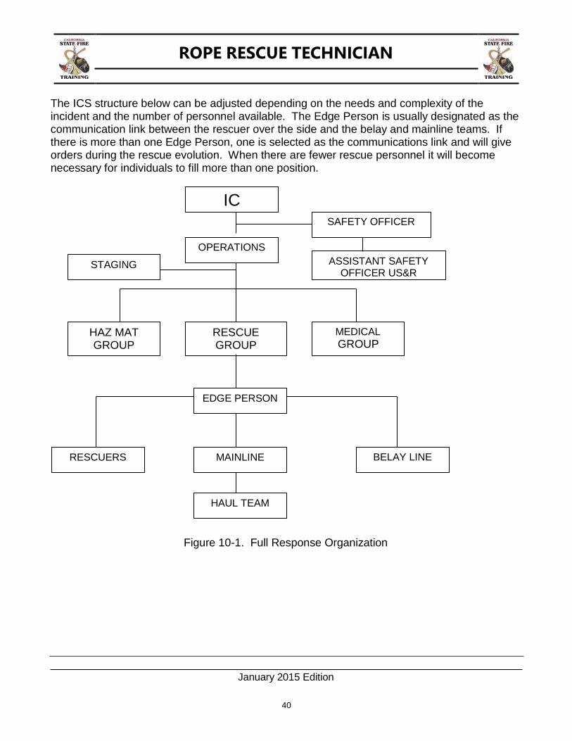
The ICS structure below can be adjusted depending on the needs and complexity of the incident and the number of personnel available. The Edge Person is usually designated as the communication link between the rescuer over the side and the belay and mainline teams. If there is more than one Edge Person, one is selected as the communications link and will give orders during the rescue evolution. When there are fewer rescue personnel it will become necessary for individuals to fill more than one position.
Figure 10-1. Full Response Organization
IC SAFETY OFFICER
ASSISTANT SAFETY OFFICER US&R
OPERATIONS
STAGING
HAZ MAT GROUP
RESCUE GROUP
MEDICAL
GROUP
EDGE PERSON
RESCUERS MAINLINE BELAY LINE
HAUL TEAM
ROPE RESCUE TECHNICIAN
January 2015 Edition
41
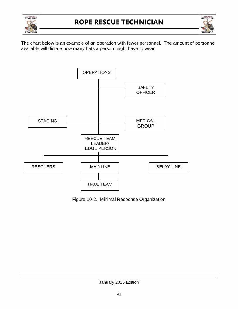
The chart below is an example of an operation with fewer personnel. The amount of personnel available will dictate how many hats a person might have to wear.
Figure 10-2. Minimal Response Organization
OPERATIONS
SAFETY OFFICER
STAGING MEDICAL
GROUP
RESCUE TEAM LEADER/
EDGE PERSON
RESCUERS MAINLINE BELAY LINE
HAUL TEAM
ROPE RESCUE TECHNICIAN
January 2015 Edition
42
SAFETY OFFICER / ASSISTANT SAFETY OFFICER US&R
A Safety Officer shall inspect and approve all system components prior to starting operations.
A Safety Officer shall ensure that personnel closer than six feet from the edge of a cliff or similar hazard are secured with travel restriction.
A Safety Officer shall ensure that all systems are pre-tensioned. Pre-tensioning a system will show how the lines will lay during the evolution. After pre-tensioning the systems make any needed adjustments to resolve any system problems encountered.
RESCUE TEAM
Rescue team members must work with their personal safety as the highest priority. (Do not become another victim) Agency SOG's are the foundation and principles upon which rescue systems are based. There is no ONE WAY to perform a rescue. However, there are principles and safe system components which must be employed. The method of combining these components may vary. The most important question is: "IS IT SAFE AND DOES IT WORK?"
The priorities in rope rescue are;
1) Lower if possible
2) Raise when necessary
3) Use helicopters when practical
4) Use motorized devices, winches, or vehicles as a last resort. (preferably only
winches made specifically for rope rescue use)
NOTE: Motorized devices winches, or vehicles do not give an indication to the topside crew that a rescuer has a foot, leg, or equipment caught. When performing a raising operation with a manual system, it will become apparent when there is a sudden increase in the load, indicating a problem.
Using a pulley system instead of a 10,000 pound winch will keep from injuring a rescuer as severely as a motorized system would. Some capstans are designed for rope rescue work and have a stall force of about 1,000 pounds. These devices are preferred over winches with a high stall force.
ROPE RESCUE TECHNICIAN
January 2015 Edition
43
The rescue must be made at a speed consistent with safety. Check the system and MAKE THE RESCUE! Success in a rescue is a combination of:
1. Training 2. Practice 3. Experience 4. Judgment
Certification and classes provide training only and possibly limited experience. This is the foundation of rescue training. The rescuer must gain the other components through training at different venues and scenarios that enhance experience and judgment. Train at higher degree of difficulty than rescuers are likely to encounter. It is important to record all training. Should an accident occur, investigators will demand to review the training records of those involved.
In some operations, the rescue team may find systems placed in service prior to their arrival. If the team will be using these systems to perform the rescue, inspect the rigging to determine if it is safe for use. If the Rescue Group Supervisor does not assign a Safety Officer, the Rescue Group Supervisor assumes the role of Safety Officer.
SELECTING A RESCUE METHOD
LOWERING SYSTEMS
Advantages: Works with gravity.
Simple friction system employed. Requires fewer people.
Disadvantages: Must have an accessible location at the bottom of the lowering evolution from which the victim can be extracted. Edge protection is needed.
RAISING SYSTEMS
Advantages: Places victim at the top where an ambulance or helicopter can be waiting to transport.
Disadvantages: Takes more equipment, personnel, and space (haul field).
Takes more expertise to run complex systems.

ROPE RESCUE TECHNICIAN
January 2015 Edition
44
HELICOPTERS
Advantages: Allows the team to access the victim where they lie.
Can get the team in and out quickly. Can ferry equipment caches quickly.
Disadvantages: Cannot fly in all conditions.
Difficult to extract victim in areas of high tree density. Creates rotor wash, which can roll rocks down the hill in scree evacuations. Cannot fly near high tension lines. Time delay in reaching the area.
SUMMARY
A successful rescue may be a combination of several of these methods. A particular method may not always work at the same location.
Example:
The team lowers a rescuer to a victim who fell down a cliff at the beach and continues to lower both victim and rescuer to the bottom of a large sandy area. Both the rescuer and victim are extracted using a helicopter. Later that day there is another rescue in the same place and now it is high tide and the waves are crashing at the bottom of the cliff and the team is unable to lower the victim and rescuer. The team must now use a haul system to raise them to safety. Never wait for a helicopter to complete an operation, the helicopter may not be able to perform the rescue. Always have an alternate plan. The most important reasons for picking a method are: IT WORKS AND IT IS SAFE.
The location of the victim and determining their condition will most likely dictate the incident objectives and the rescue method chosen. Accessing the victim is the next step in the operation. The condition of the victim may dictate whether medical personnel rappel or are lowered into place, prior to a litter basket going over the edge. The medical personnel would stabilize and either package or assist with packaging the victim. This depends on whether medical personnel rappelled ahead of the litter basket or came down with the litter basket.
ROPE RESCUE TECHNICIAN
January 2015 Edition
45
CHAPTER 11: KNOT PASSING
TERMINAL LEARNING OBJECTIVE
The student will pass a knot through a lowering and raising system
ENABLING LEARNING OBJECTIVES
1. Pass a knot through a friction device. 2. Pass a knot while through a belay during lowering and raising operations. 3. Pass a knot through a change of direction pulley during a raising operation on the main
line.
PASSING A KNOT WHILE LOWERING
When a rope rescue evolution is beyond the reach of the team’s longest rope they will end up tying two (or more) ropes together to reach the target. Once the ropes are tied together it is inevitable that the knot will have to be “passed” through the systems. While there are many ways to perform a knot pass, this chapter will highlight one way.
Passing a knot on the main line requires the knot to travel through the descent control device for lowering evolutions and through the mechanical advantage system for raising evolutions. The main line and belay line operate as normal up to the point when the knot pass must occur.
It is important to remember that the knot pass won’t come as a surprise, after all someone tied the ropes together! This means that the proper systems can be constructed and in place prior to the knot approaching the point(s) it needs to pass.
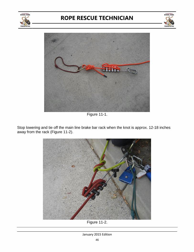
This example will start by passing a knot through a brake bar rack during a lowering evolution with what is called a “piggyback”. While the main line is being lowered a second rescuer constructs the piggyback system.
A separate rope (preferably a different color) is procured and a figure eight on a bight tied into its end. A carabiner is then clipped into the figure eight on a bight. The rope is then reeved through a separate brake bar rack with the figure eight on a bight approx. 6 inches from the top of the rack. Tie off the rack (Figure 11-1).
ROPE RESCUE TECHNICIAN
January 2015 Edition
46
Figure 11-1.
Stop lowering and tie off the main line brake bar rack when the knot is approx. 12-18 inches away from the rack (Figure 11-2).
Figure 11-2.
ROPE RESCUE TECHNICIAN
January 2015 Edition
47
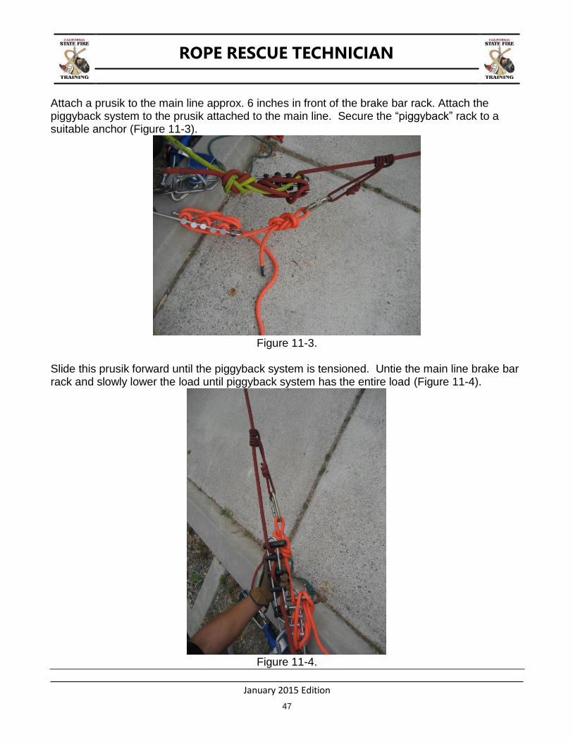
Attach a prusik to the main line approx. 6 inches in front of the brake bar rack. Attach the piggyback system to the prusik attached to the main line. Secure the “piggyback” rack to a suitable anchor (Figure 11-3).
Figure 11-3.
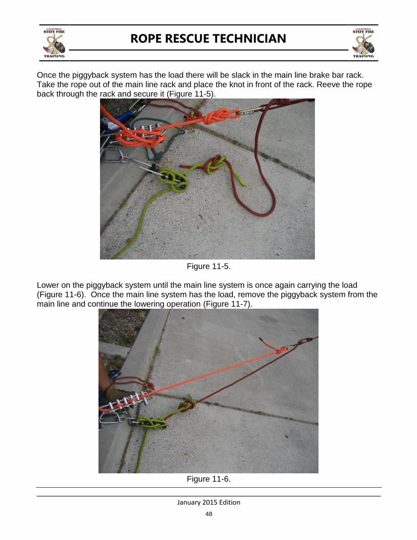
Slide this prusik forward until the piggyback system is tensioned. Untie the main line brake bar rack and slowly lower the load until piggyback system has the entire load (Figure 11-4).
Figure 11-4.
ROPE RESCUE TECHNICIAN
January 2015 Edition
48
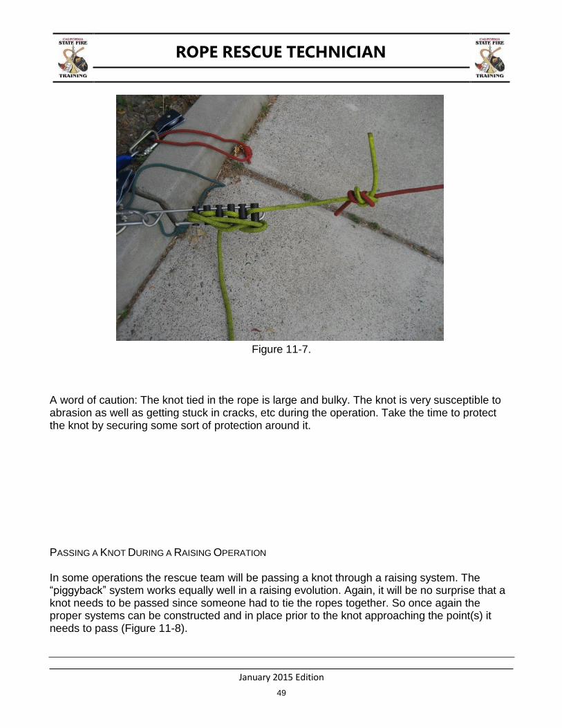
Once the piggyback system has the load there will be slack in the main line brake bar rack. Take the rope out of the main line rack and place the knot in front of the rack. Reeve the rope back through the rack and secure it (Figure 11-5).
Figure 11-5.
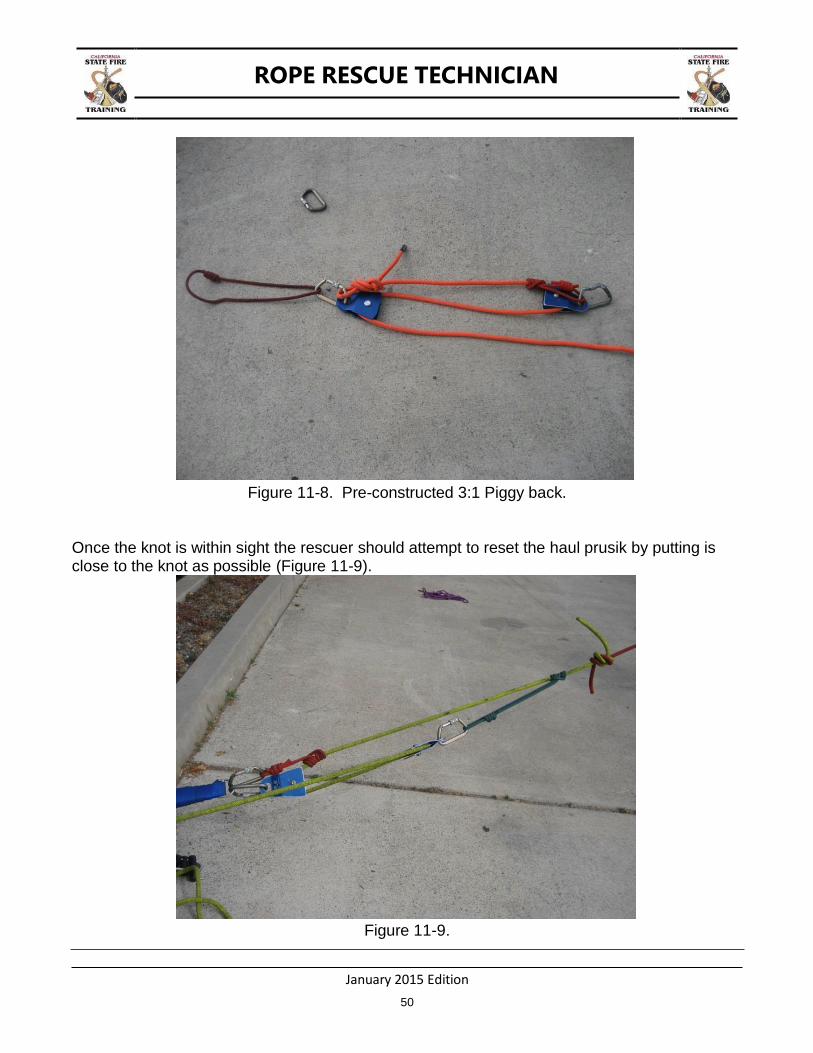
Lower on the piggyback system until the main line system is once again carrying the load (Figure 11-6). Once the main line system has the load, remove the piggyback system from the main line and continue the lowering operation (Figure 11-7).
Figure 11-6.
ROPE RESCUE TECHNICIAN
January 2015 Edition
49
Figure 11-7.
A word of caution: The knot tied in the rope is large and bulky. The knot is very susceptible to abrasion as well as getting stuck in cracks, etc during the operation. Take the time to protect the knot by securing some sort of protection around it.
PASSING A KNOT DURING A RAISING OPERATION
In some operations the rescue team will be passing a knot through a raising system. The “piggyback” system works equally well in a raising evolution. Again, it will be no surprise that a knot needs to be passed since someone had to tie the ropes together. So once again the proper systems can be constructed and in place prior to the knot approaching the point(s) it needs to pass (Figure 11-8).
ROPE RESCUE TECHNICIAN
January 2015 Edition
50
Figure 11-8. Pre-constructed 3:1 Piggy back.
Once the knot is within sight the rescuer should attempt to reset the haul prusik by putting is close to the knot as possible (Figure 11-9).
Figure 11-9.

ROPE RESCUE TECHNICIAN
January 2015 Edition
51
Once the haul system has “two blocked”, attach the piggyback system to the haul line using a prusik (again it is easier to see what you are doing if you use separate color ropes for the main and piggyback system). Attach the piggyback prusik as far in front of the knot as possible. Secure the other end of the piggyback system to a suitable anchor. The rescue team can now haul on the piggyback system.
Figure 11-10.
As the load is raised the knot will approach the main line ratchet and change of direction pulley. Once the knot reaches this area disconnect it from the main line anchor system. Continue hauling on the piggyback system until the knot has reached a point where it will be well past the change of direction and mechanical advantage pulleys. At this point reassemble the main line mechanical advantage system and transfer the load from the piggyback system back to the main line.
KNOT PASSING THROUGH A TANDEM PRUSIK BELAY
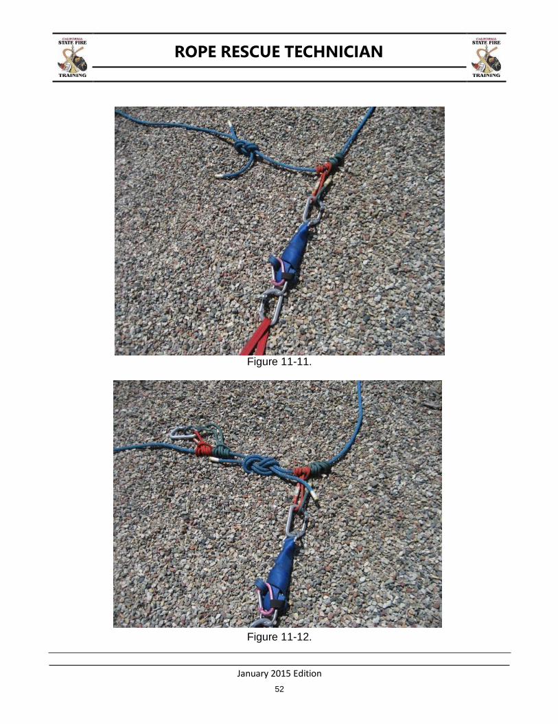
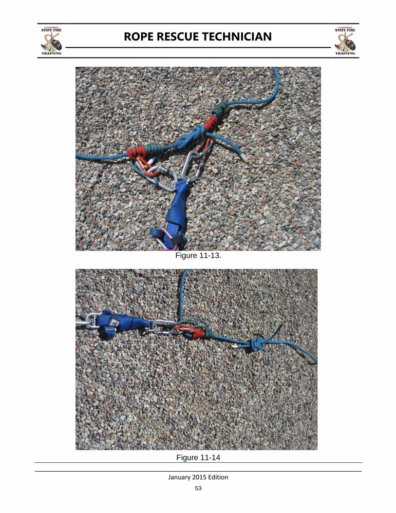
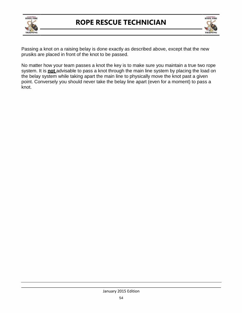
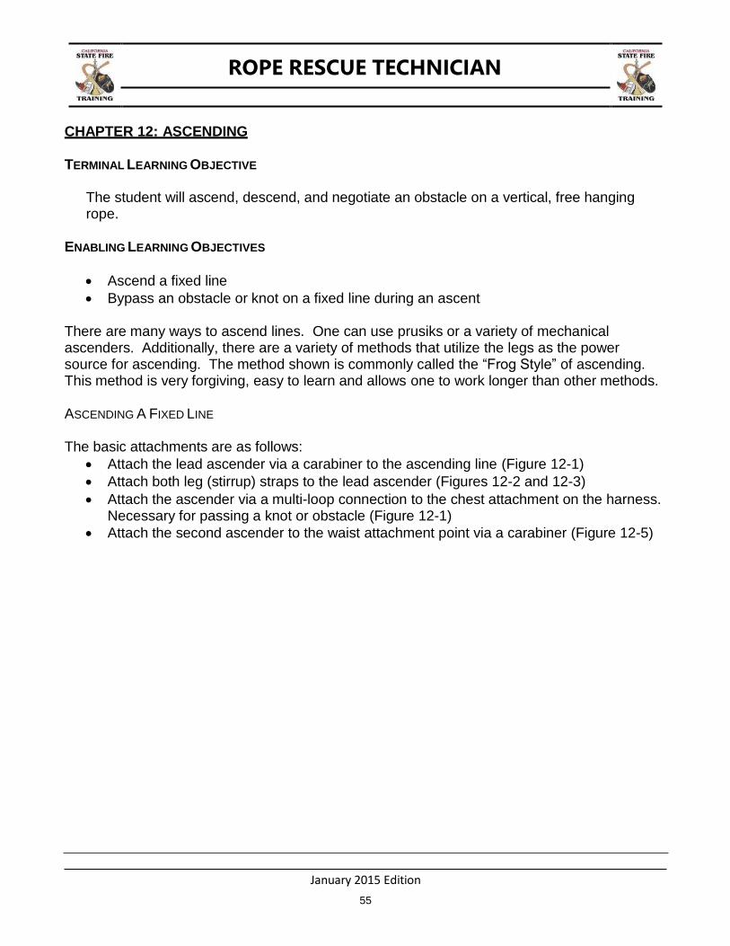
Transferring a knot through the tandem prusik belay system when it arrives at the tandem prusiks (Figure 11-11) during a lowering operation is done as follows: While belaying a load on the lowering system, have another rescuer attach a set of tandem prusiks on the anchor side of the knot to be passed and attach them to a carabiner (Figure 11-12). As the prusiks approach the load release device have the lowering team stop. Attach the extra carabiner that was placed on the second set of tandem prusiks to distal end of the LRD (Figure 11-13). Once the new prusiks are attached to the system remove the ones in front of the knot (Figure 11-14).
ROPE RESCUE TECHNICIAN
January 2015 Edition
52
Figure 11-11.
Figure 11-12.
ROPE RESCUE TECHNICIAN
January 2015 Edition
53
Figure 11-13.
Figure 11-14
ROPE RESCUE TECHNICIAN
January 2015 Edition
54
Passing a knot on a raising belay is done exactly as described above, except that the new prusiks are placed in front of the knot to be passed.
No matter how your team passes a knot the key is to make sure you maintain a true two rope system. It is not advisable to pass a knot through the main line system by placing the load on the belay system while taking apart the main line to physically move the knot past a given point. Conversely you should never take the belay line apart (even for a moment) to pass a knot.
ROPE RESCUE TECHNICIAN
January 2015 Edition
55
CHAPTER 12: ASCENDING
TERMINAL LEARNING OBJECTIVE
The student will ascend, descend, and negotiate an obstacle on a vertical, free hanging rope.
ENABLING LEARNING OBJECTIVES
Ascend a fixed line
Bypass an obstacle or knot on a fixed line during an ascent
There are many ways to ascend lines. One can use prusiks or a variety of mechanical ascenders. Additionally, there are a variety of methods that utilize the legs as the power source for ascending. The method shown is commonly called the “Frog Style” of ascending. This method is very forgiving, easy to learn and allows one to work longer than other methods.
ASCENDING A FIXED LINE
The basic attachments are as follows:
Attach the lead ascender via a carabiner to the ascending line (Figure 12-1)
Attach both leg (stirrup) straps to the lead ascender (Figures 12-2 and 12-3)
Attach the ascender via a multi-loop connection to the chest attachment on the harness. Necessary for passing a knot or obstacle (Figure 12-1)
Attach the second ascender to the waist attachment point via a carabiner (Figure 12-5)

ROPE RESCUE TECHNICIAN
January 2015 Edition
56
Figure 12-1. Ascending Attachment Points
Lead ascender attachment to line Both leg strap attachments to ascender
Gibbs ascender 2nd
attachment point
Ascender attached to waist
Multi-loop attachment to chest & ascender

ROPE RESCUE TECHNICIAN
January 2015 Edition
57
Figure 12-2. Ascending Attachment Points
Ascending the Rope Leg Stirrups Attached to lead Ascender
Extension Strap attached to Ascender and Waist

ROPE RESCUE TECHNICIAN
January 2015 Edition
58
Figure 12-3. Attaching foot stirrups
Foot stirrup attachment and adjustment
Foot stirrup attached
ROPE RESCUE TECHNICIAN
January 2015 Edition
59
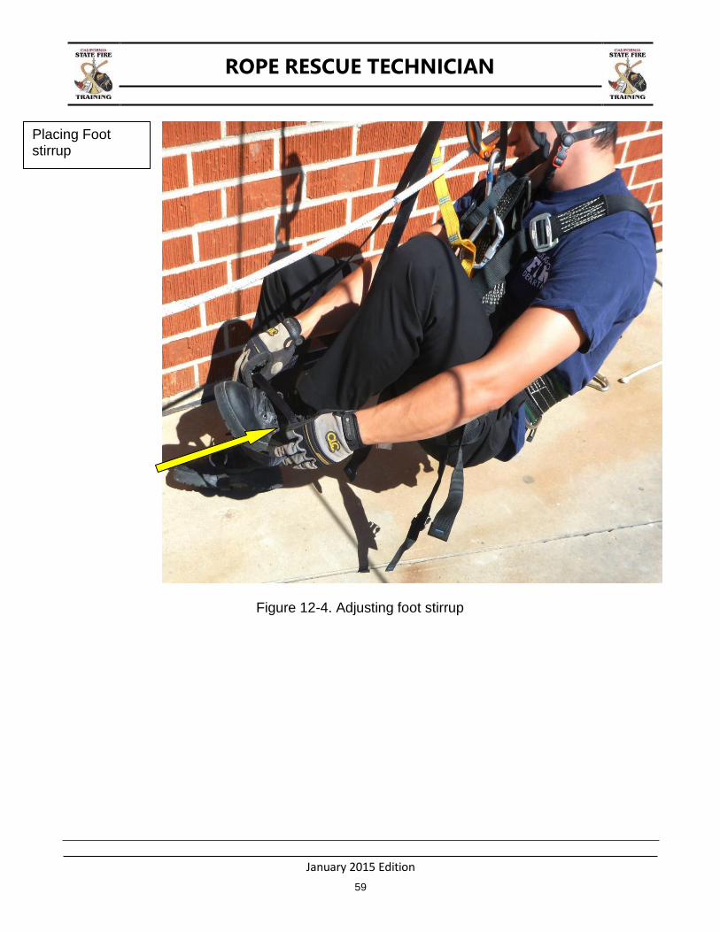
Figure 12-4. Adjusting foot stirrup
Placing Foot stirrup

ROPE RESCUE TECHNICIAN
January 2015 Edition
60
Figure 12-5. Tensioning foot stirrups
Adjusting Foot stirrup
ROPE RESCUE TECHNICIAN
January 2015 Edition
61
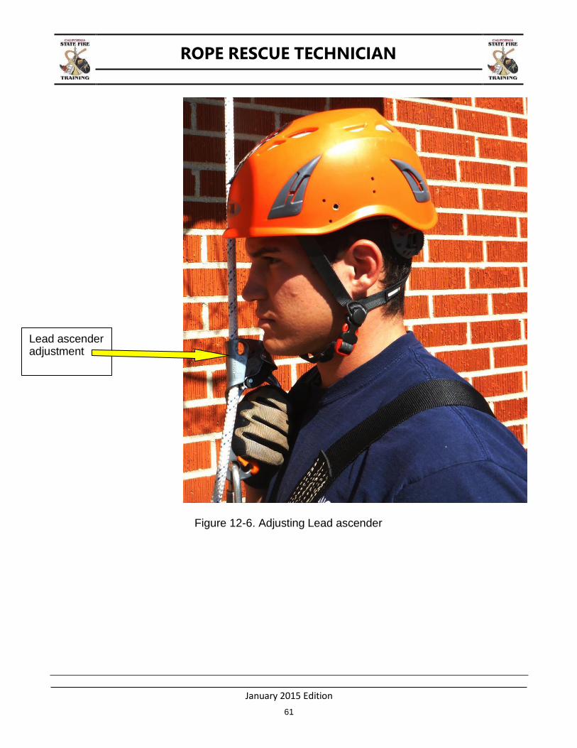
Figure 12-6. Adjusting Lead ascender
Lead ascender adjustment
ROPE RESCUE TECHNICIAN
January 2015 Edition
62
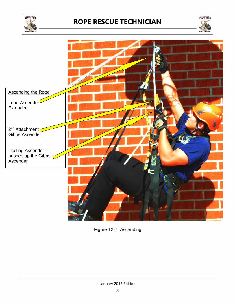
Figure 12-7. Ascending
Ascending the Rope Lead Ascender Extended
2nd Attachment Gibbs Ascender
Trailing Ascender pushes up the Gibbs Ascender
ROPE RESCUE TECHNICIAN
January 2015 Edition
63
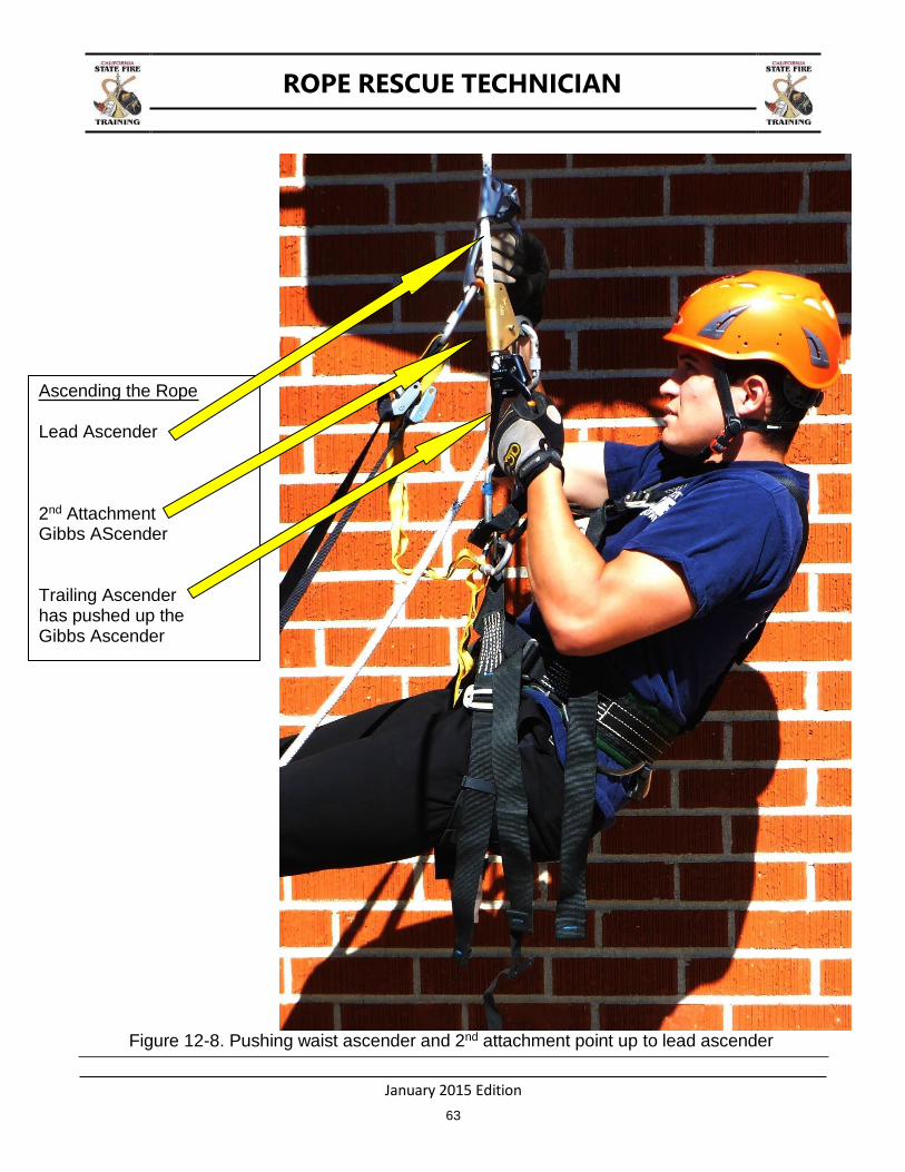
Ascending the Rope
Lead Ascender
2nd Attachment Gibbs AScender
Trailing Ascender has pushed up the Gibbs Ascender
Figure 12-8. Pushing waist ascender and 2nd attachment point up to lead ascender
ROPE RESCUE TECHNICIAN
January 2015 Edition
64
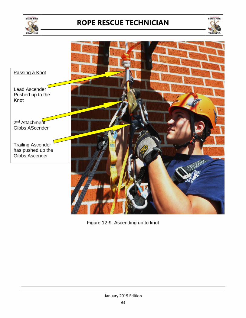
Figure 12-9. Ascending up to knot
Passing a Knot
Lead Ascender Pushed up to the Knot
2nd Attachment Gibbs AScender
Trailing Ascender has pushed up the Gibbs Ascender
ROPE RESCUE TECHNICIAN
January 2015 Edition
65
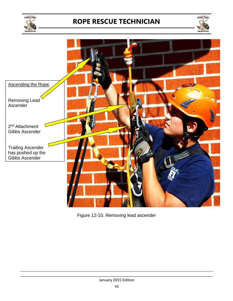
Figure 12-10. Removing lead ascender
Ascending the Rope
Removing Lead Ascender
2nd Attachment Gibbs Ascender
Trailing Ascender has pushed up the Gibbs Ascender
ROPE RESCUE TECHNICIAN
January 2015 Edition
66
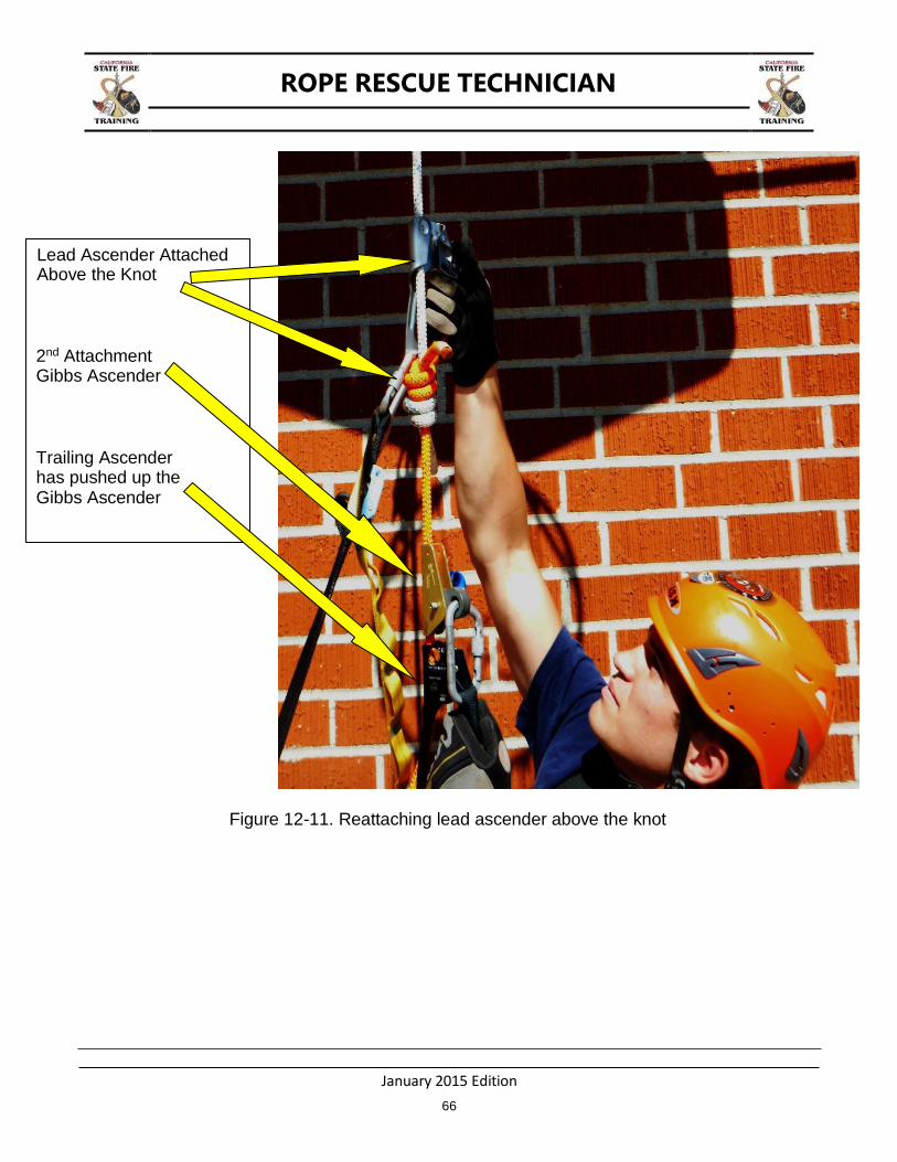
Figure 12-11. Reattaching lead ascender above the knot
Lead Ascender Attached Above the Knot
2nd Attachment Gibbs Ascender
Trailing Ascender has pushed up the Gibbs Ascender
ROPE RESCUE TECHNICIAN
January 2015 Edition
67
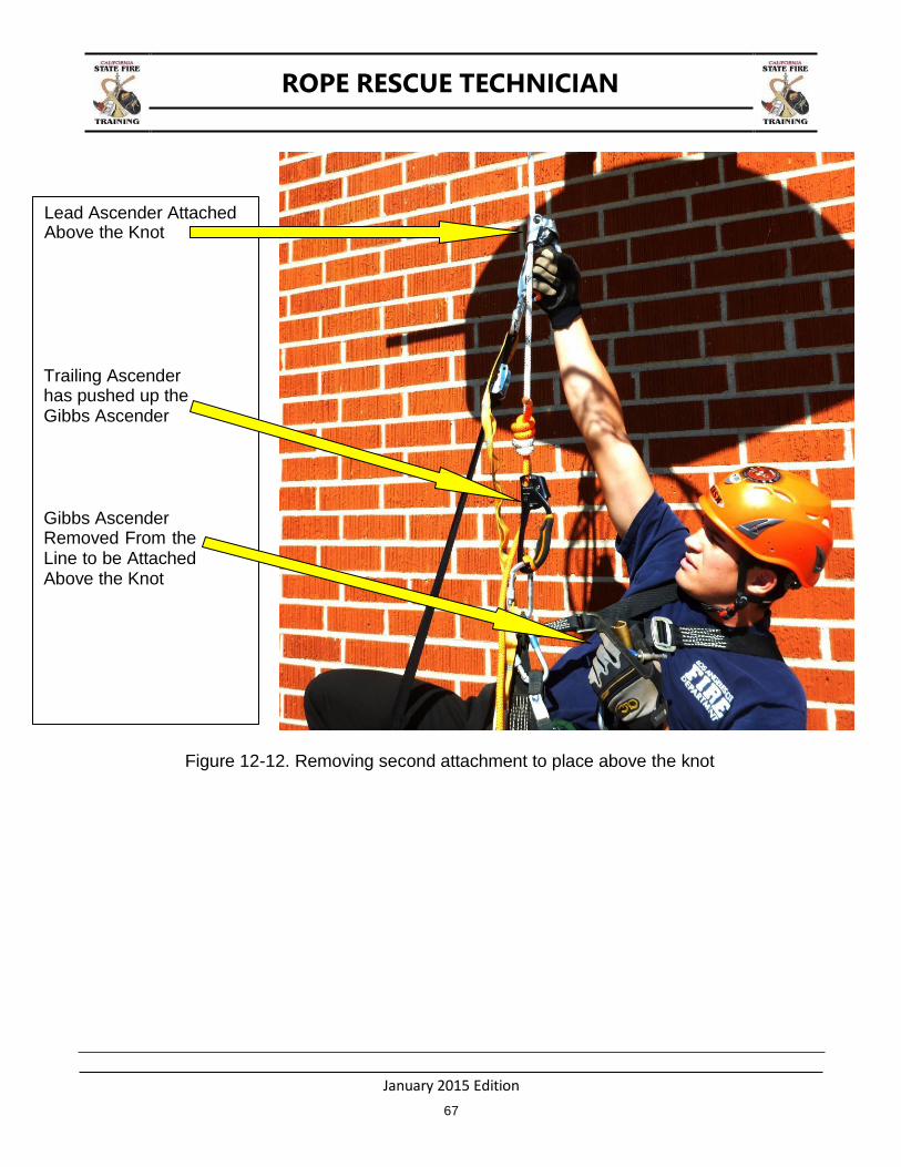
Figure 12-12. Removing second attachment to place above the knot
Lead Ascender Attached Above the Knot
Trailing Ascender has pushed up the Gibbs Ascender
Gibbs Ascender Removed From the Line to be Attached Above the Knot
ROPE RESCUE TECHNICIAN
January 2015 Edition
68
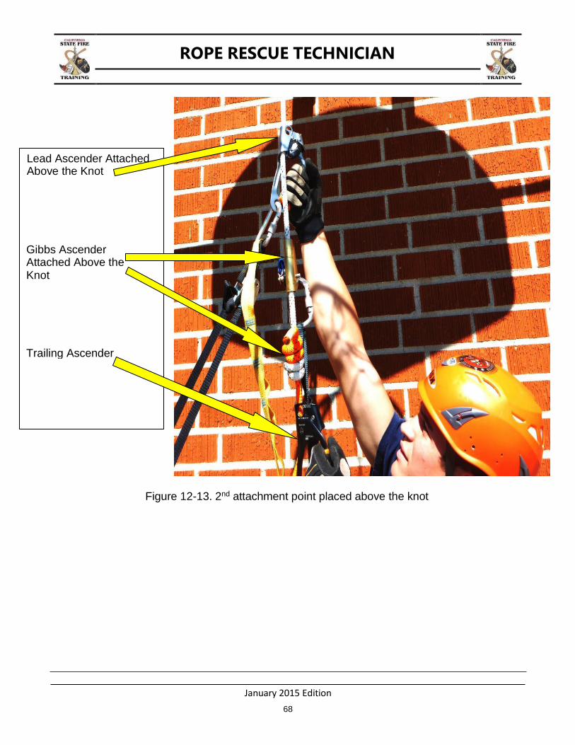
Figure 12-13. 2nd attachment point placed above the knot
Lead Ascender Attached Above the Knot
Gibbs Ascender Attached Above the Knot
Trailing Ascender
ROPE RESCUE TECHNICIAN
January 2015 Edition
69
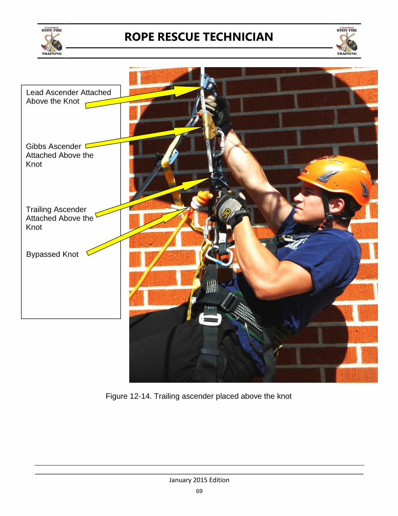
Figure 12-14. Trailing ascender placed above the knot
Lead Ascender Attached Above the Knot
Gibbs Ascender Attached Above the Knot
Trailing Ascender Attached Above the Knot
Bypassed Knot
ROPE RESCUE TECHNICIAN
January 2015 Edition
70
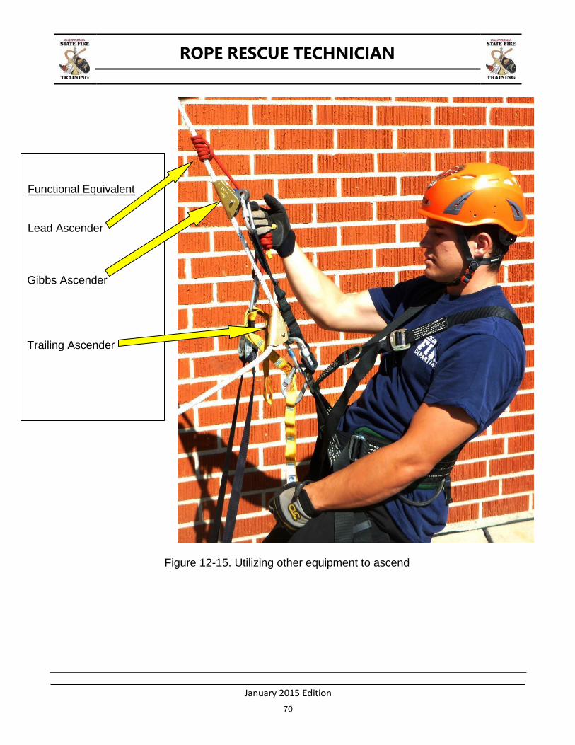
Figure 12-15. Utilizing other equipment to ascend
Functional Equivalent
Lead Ascender
Gibbs Ascender
Trailing Ascender
ROPE RESCUE TECHNICIAN
January 2015 Edition
71
CHAPTER 13: PICK OFFS
TERMINAL LEARNING OBJECTIVE
The student will perform a victim pick off.
ENABLING LEARNING OBJECTIVES
1. Construct a two line system for a victim pick off. 2. Attach a victim to a two line system. 3. Perform a pick-off of a supported/suspended victim. 4. Perform a pick-off of an unsupported victim.
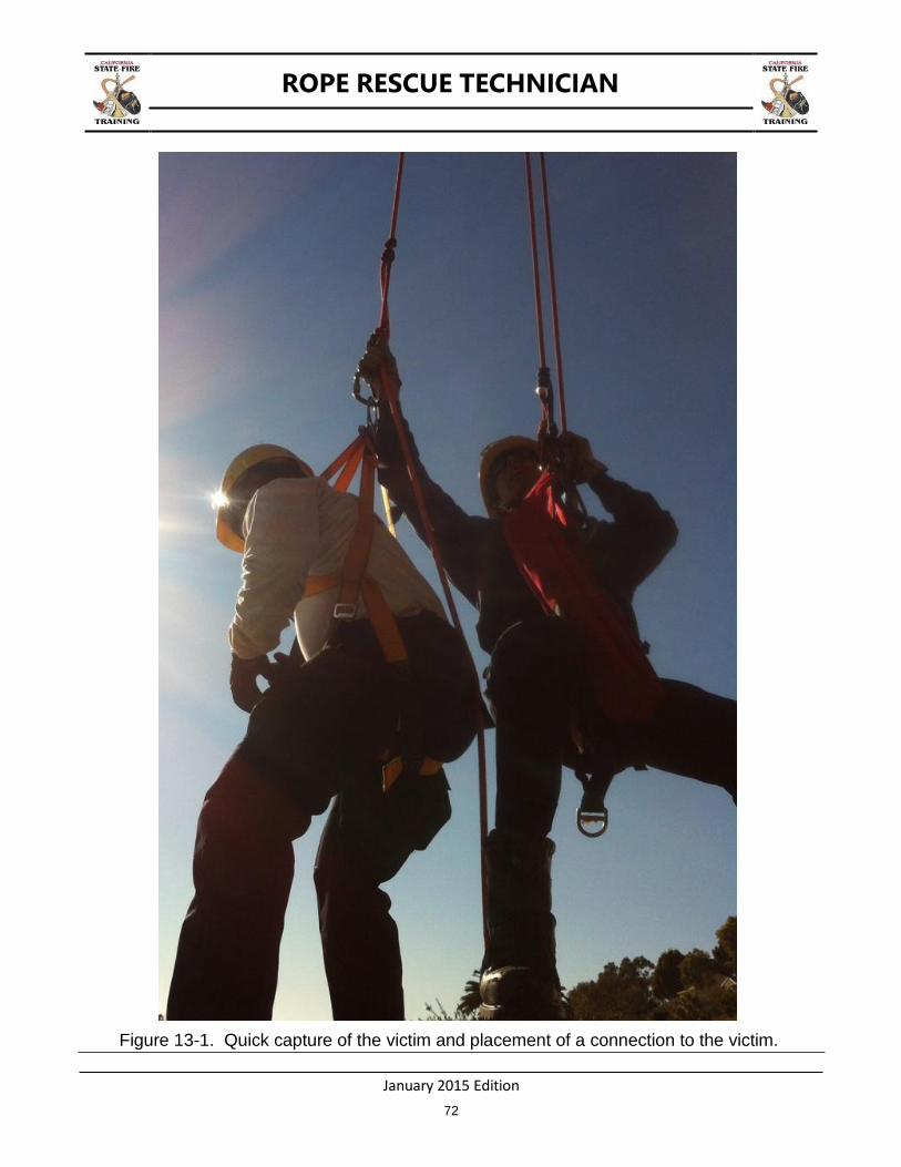
PICK OFF RESCUES
Rescuers may be faced with situations in which a victim is supported/suspended mid-slope or mid structure from a cable or rope. Victims may also be found in unsupported positions with no attachment for support. In either case the rescuer must be prepared to capture the victim quickly to prevent the victim from falling or to minimize injury. After the victim is captured the victim should be placed on the rescue system as soon as practical.
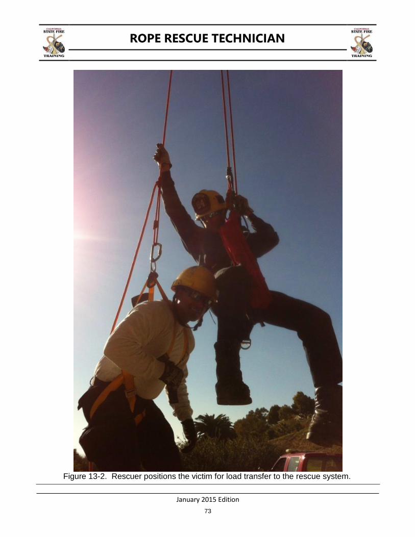
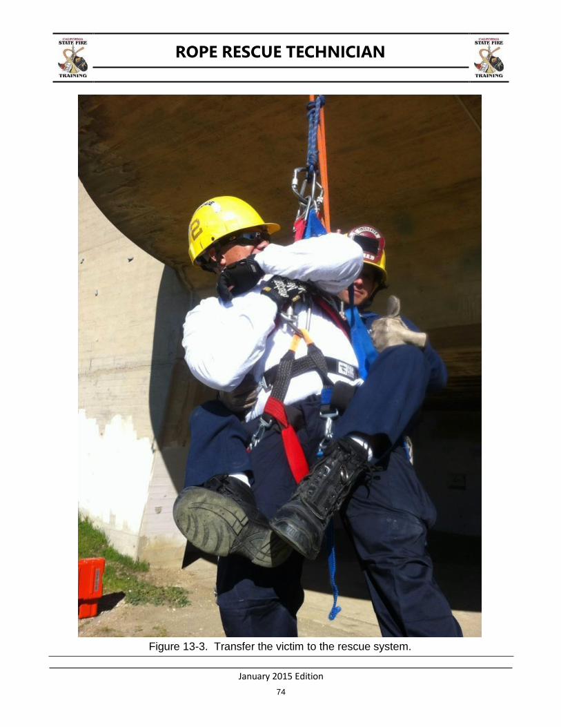
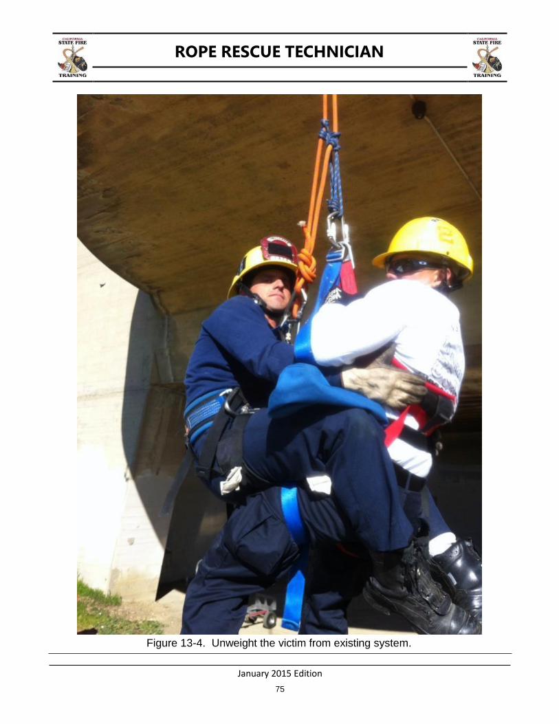
After the rescue system has been rigged, the sequence of a pick off rescue generally is in the following order:
1. Quick capture of the victim.
2. Position the victim for efficient load transfer.
3. Place the victim on the rescue system.
4. Unweight the victim system if appropriate.
5. Lower or raise the victim and rescuer to safety as appropriate.
ROPE RESCUE TECHNICIAN
January 2015 Edition
72
Figure 13-1. Quick capture of the victim and placement of a connection to the victim.
ROPE RESCUE TECHNICIAN
January 2015 Edition
73
Figure 13-2. Rescuer positions the victim for load transfer to the rescue system.
ROPE RESCUE TECHNICIAN
January 2015 Edition
74
Figure 13-3. Transfer the victim to the rescue system.
ROPE RESCUE TECHNICIAN
January 2015 Edition
75
Figure 13-4. Unweight the victim from existing system.
ROPE RESCUE TECHNICIAN
January 2015 Edition
76
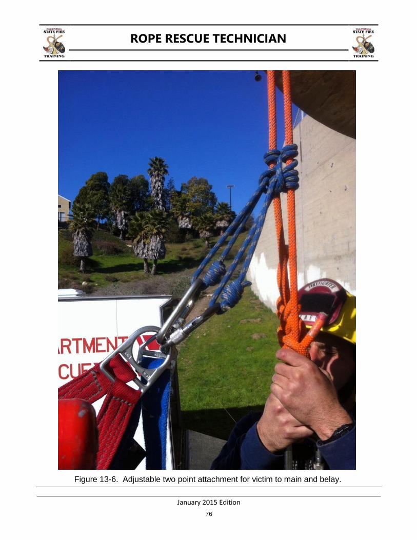
Figure 13-6. Adjustable two point attachment for victim to main and belay.
ROPE RESCUE TECHNICIAN
January 2015 Edition
77
CHAPTER 14: PROTECTED CLIMBING
TERMINAL LEARNING OBJECTIVE
The student will perform a protected climb on a natural or manmade structure.
ENABLING LEARNING OBJECTIVES
1. Climb a manmade structure utilizing a bottom belay or Double Bypass Lanyard; or 2. Climb a landscape feature (e.g. arborist tree rescue) utilizing a bottom belay.
PROTECTED CLIMBING
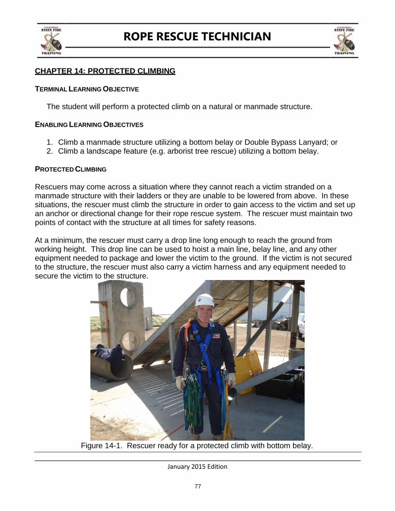
Rescuers may come across a situation where they cannot reach a victim stranded on a manmade structure with their ladders or they are unable to be lowered from above. In these situations, the rescuer must climb the structure in order to gain access to the victim and set up an anchor or directional change for their rope rescue system. The rescuer must maintain two points of contact with the structure at all times for safety reasons.
At a minimum, the rescuer must carry a drop line long enough to reach the ground from working height. This drop line can be used to hoist a main line, belay line, and any other equipment needed to package and lower the victim to the ground. If the victim is not secured to the structure, the rescuer must also carry a victim harness and any equipment needed to secure the victim to the structure.
Figure 14-1. Rescuer ready for a protected climb with bottom belay.
ROPE RESCUE TECHNICIAN
January 2015 Edition
78
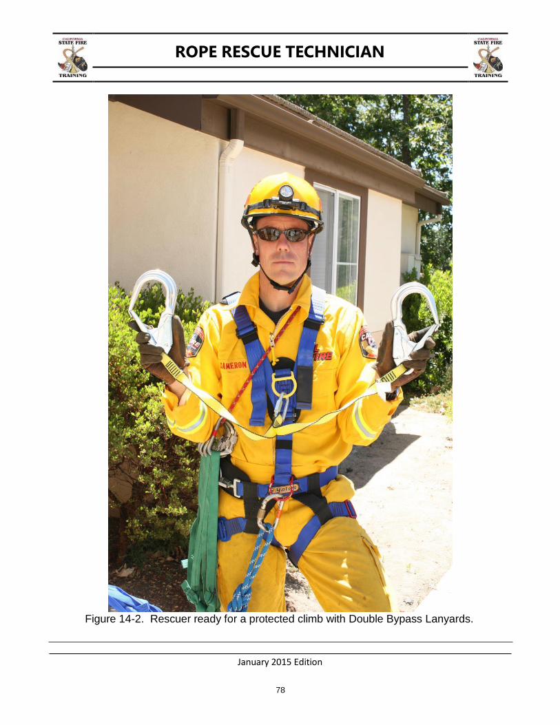
Figure 14-2. Rescuer ready for a protected climb with Double Bypass Lanyards.
ROPE RESCUE TECHNICIAN
January 2015 Edition
79
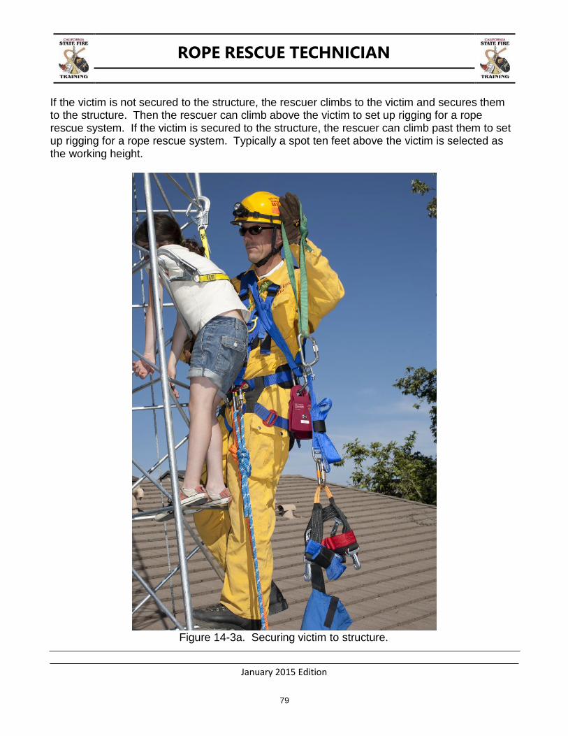
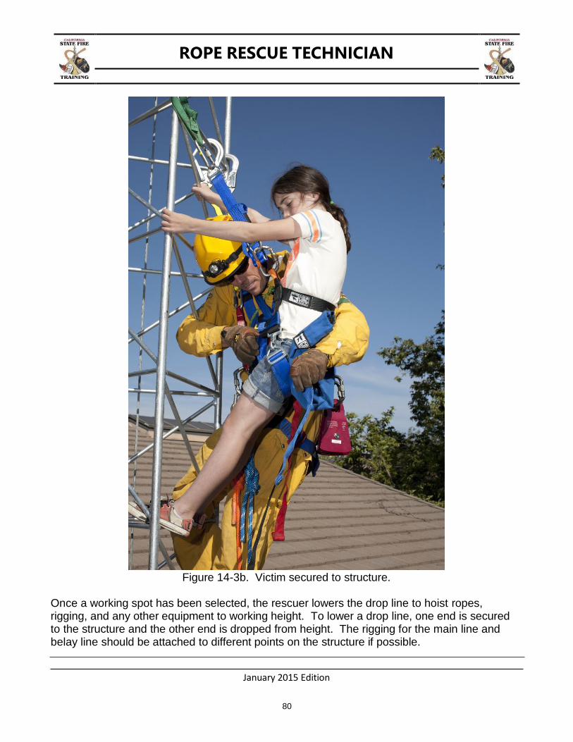
If the victim is not secured to the structure, the rescuer climbs to the victim and secures them to the structure. Then the rescuer can climb above the victim to set up rigging for a rope rescue system. If the victim is secured to the structure, the rescuer can climb past them to set up rigging for a rope rescue system. Typically a spot ten feet above the victim is selected as the working height.
Figure 14-3a. Securing victim to structure.
ROPE RESCUE TECHNICIAN
January 2015 Edition
80
Figure 14-3b. Victim secured to structure.
Once a working spot has been selected, the rescuer lowers the drop line to hoist ropes, rigging, and any other equipment to working height. To lower a drop line, one end is secured to the structure and the other end is dropped from height. The rigging for the main line and belay line should be attached to different points on the structure if possible.

ROPE RESCUE TECHNICIAN
January 2015 Edition
81
Figure 14-4. Rigging set-up at working height (change of direction).
Alternatively, in large towers, multiple rescuers may opt to ascend the tower and operate the main and belay from a working area above the victim. Rigging set-up at working height (anchors for main and safety/belay).
The rescuer can now descend to the victim and package them for lowering. The belay line is attached to the victim first, then the main line. Tag lines may also be needed in order to keep the victim off the structure. The victim is now lowered to the ground.

ROPE RESCUE TECHNICIAN
January 2015 Edition
82
Figure 14-5. Victim lowering attachment points.
Figure 14-6a. Rescuer and victim being lowered to the ground (aerial view).
ROPE RESCUE TECHNICIAN
January 2015 Edition
83
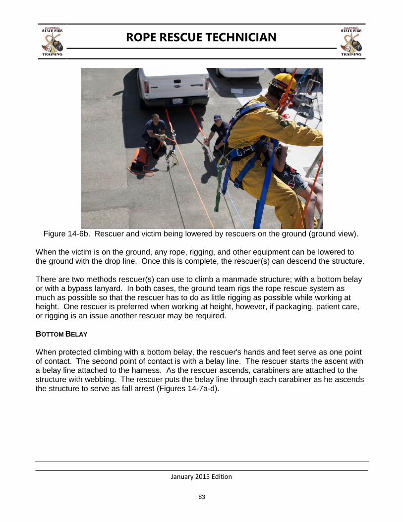
Figure 14-6b. Rescuer and victim being lowered by rescuers on the ground (ground view).
When the victim is on the ground, any rope, rigging, and other equipment can be lowered to the ground with the drop line. Once this is complete, the rescuer(s) can descend the structure.
There are two methods rescuer(s) can use to climb a manmade structure; with a bottom belay or with a bypass lanyard. In both cases, the ground team rigs the rope rescue system as much as possible so that the rescuer has to do as little rigging as possible while working at height. One rescuer is preferred when working at height, however, if packaging, patient care, or rigging is an issue another rescuer may be required.
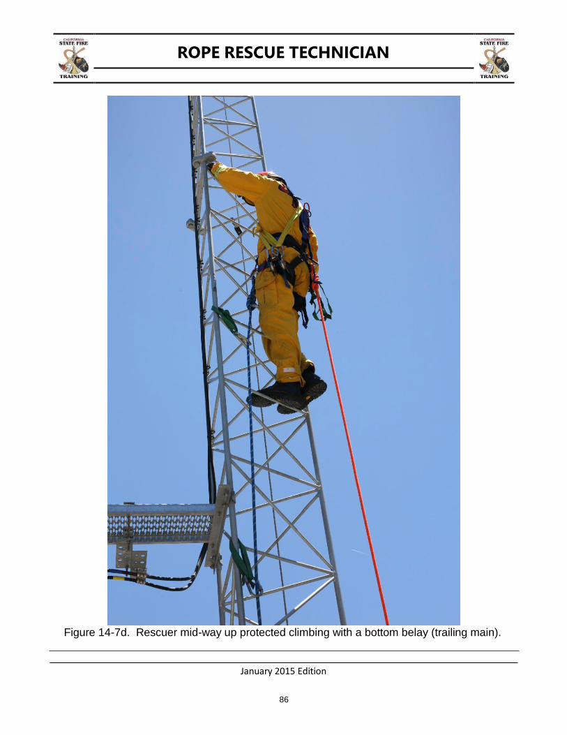
BOTTOM BELAY
When protected climbing with a bottom belay, the rescuer's hands and feet serve as one point of contact. The second point of contact is with a belay line. The rescuer starts the ascent with a belay line attached to the harness. As the rescuer ascends, carabiners are attached to the structure with webbing. The rescuer puts the belay line through each carabiner as he ascends the structure to serve as fall arrest (Figures 14-7a-d).

ROPE RESCUE TECHNICIAN
January 2015 Edition
84
Figure 14-7a. Protected climb rigging with a bottom belay and main (for lowering).
Figure 14-7b. Protected climb rigging change of direction at bottom.

ROPE RESCUE TECHNICIAN
January 2015 Edition
85
Figure 14-7c. Rescuer beginning protected climbing with a bottom belay.
ROPE RESCUE TECHNICIAN
January 2015 Edition
86
Figure 14-7d. Rescuer mid-way up protected climbing with a bottom belay (trailing main).
ROPE RESCUE TECHNICIAN
January 2015 Edition
87
When rigging the victim for lowering, the rescuer can remove the Safety/Belay Line from himself and attach it to the victim. The rescuer must be secured to the structure before removing the Safety/Belay Line.
When the victim is on the ground, the Safety/Belay Line must be retrieved so that the rescuer can reattach it to his harness before descending the structure. The rescuer can gather any equipment attached to the structure on the way down.
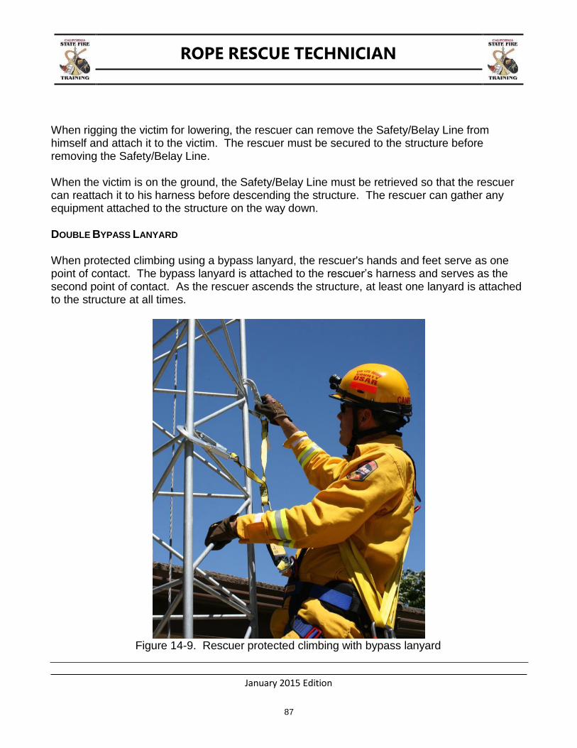
DOUBLE BYPASS LANYARD
When protected climbing using a bypass lanyard, the rescuer's hands and feet serve as one point of contact. The bypass lanyard is attached to the rescuer’s harness and serves as the second point of contact. As the rescuer ascends the structure, at least one lanyard is attached to the structure at all times.
Figure 14-9. Rescuer protected climbing with bypass lanyard

ROPE RESCUE TECHNICIAN
January 2015 Edition
88
When negotiating obstacles, one lanyard is attached to the structure. The other lanyard is attached to the structure on the other side of the obstacle. Once the rescuer passes the obstacle, the lanyard still attached to the structure on the first side can be disconnected. The rescuer can now continue their ascent.
Figure 14-10. Rescuer negotiating obstacle with bypass lanyard

ROPE RESCUE TECHNICIAN
January 2015 Edition
89
CHAPTER 15: HIGH ANGLE LITTER RIGGING AND TENDING
TERMINAL LEARNING OBJECTIVE
The student will rig and tend an occupied rescue litter in a high angle environment.
ENABLING LEARNING OBJECTIVES
1. Package a patient into a rescue litter.
2. Attach the occupied rescue litter to a rope rescue system with a litter tender.
3. Tend the litter basket operation both above and below the basket
4. Negotiate obstacles and manipulate the occupied litter while being raised and lowered.
5. Move the occupied litter up and over an edge.
There may be times that require a non-ambulatory patient to be raised or lowered, in a rescue litter, while being tended by a litter attendant. This may be due to patient care needs, edge management issues, patient packaging issues, and/or the need to negotiate obstacles.
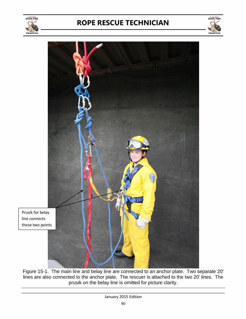
RESCUER ATTACHMENT
The rescuer must be attached to the system with two points of attachment. This can be accomplished by using two separate ten to twenty foot lines attached to the top of the litter rigging or by tying long tails in the main line and belay line. The main line attachment and belay line attachments need to be adjustable. This will allow the rescuer to tend to the patient and adjust the rigging, if needed, while being able to maneuver above, below, and around the rescue litter. Each line must either be attached to the rescuer or have a stopper knot tied in the end to prevent the device used for adjustment from sliding off the line.
ROPE RESCUE TECHNICIAN
January 2015 Edition
90
Figure 15-1. The main line and belay line are connected to an anchor plate. Two separate 20' lines are also connected to the anchor plate. The rescuer is attached to the two 20' lines. The
prusik on the belay line is omitted for picture clarity.
Prusik for belay
line connects
these two points
ROPE RESCUE TECHNICIAN
January 2015 Edition
91
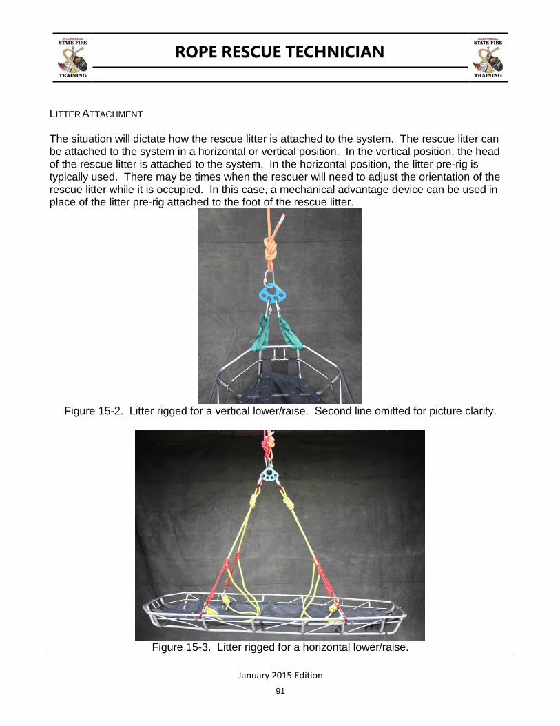
LITTER ATTACHMENT
The situation will dictate how the rescue litter is attached to the system. The rescue litter can be attached to the system in a horizontal or vertical position. In the vertical position, the head of the rescue litter is attached to the system. In the horizontal position, the litter pre-rig is typically used. There may be times when the rescuer will need to adjust the orientation of the rescue litter while it is occupied. In this case, a mechanical advantage device can be used in place of the litter pre-rig attached to the foot of the rescue litter.
Figure 15-2. Litter rigged for a vertical lower/raise. Second line omitted for picture clarity.
Figure 15-3. Litter rigged for a horizontal lower/raise.
ROPE RESCUE TECHNICIAN
January 2015 Edition
92
PATIENT CARE
The rescue litter can be positioned head high, which is preferred for conscious patients or head dependant for patients in shock. For patients who are vomiting, the litter tender may need to position the patient laterally.
EDGE MANAGEMENT
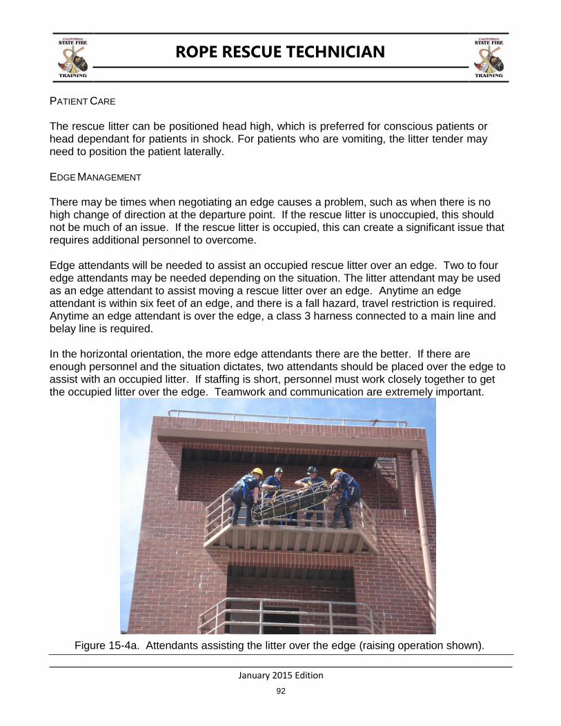
There may be times when negotiating an edge causes a problem, such as when there is no high change of direction at the departure point. If the rescue litter is unoccupied, this should not be much of an issue. If the rescue litter is occupied, this can create a significant issue that requires additional personnel to overcome.
Edge attendants will be needed to assist an occupied rescue litter over an edge. Two to four edge attendants may be needed depending on the situation. The litter attendant may be used as an edge attendant to assist moving a rescue litter over an edge. Anytime an edge attendant is within six feet of an edge, and there is a fall hazard, travel restriction is required. Anytime an edge attendant is over the edge, a class 3 harness connected to a main line and belay line is required.
In the horizontal orientation, the more edge attendants there are the better. If there are enough personnel and the situation dictates, two attendants should be placed over the edge to assist with an occupied litter. If staffing is short, personnel must work closely together to get the occupied litter over the edge. Teamwork and communication are extremely important.
Figure 15-4a. Attendants assisting the litter over the edge (raising operation shown).
ROPE RESCUE TECHNICIAN
January 2015 Edition
93
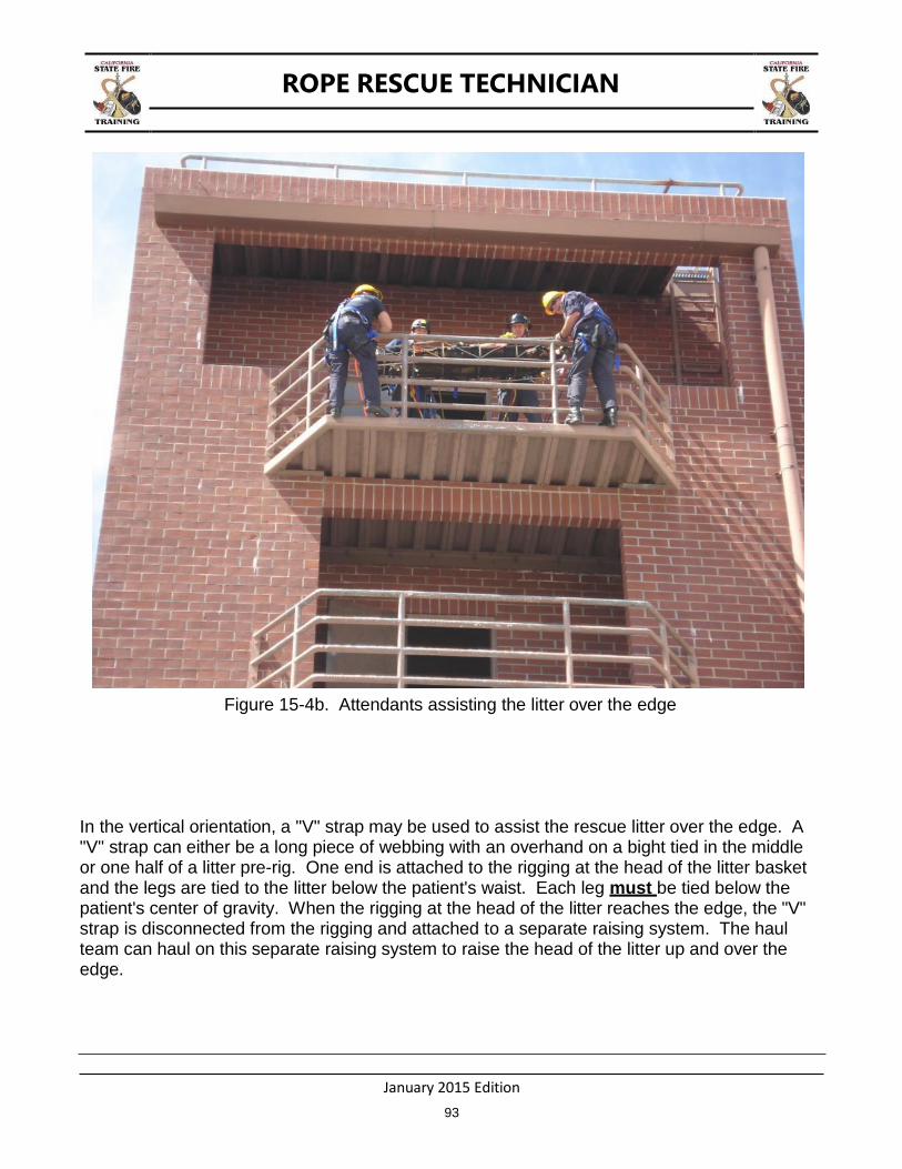
Figure 15-4b. Attendants assisting the litter over the edge
In the vertical orientation, a "V" strap may be used to assist the rescue litter over the edge. A "V" strap can either be a long piece of webbing with an overhand on a bight tied in the middle or one half of a litter pre-rig. One end is attached to the rigging at the head of the litter basket and the legs are tied to the litter below the patient's waist. Each leg must be tied below the patient's center of gravity. When the rigging at the head of the litter reaches the edge, the "V" strap is disconnected from the rigging and attached to a separate raising system. The haul team can haul on this separate raising system to raise the head of the litter up and over the edge.

ROPE RESCUE TECHNICIAN
January 2015 Edition
94
Figure 15-5. One half of the litter pre-rig used as a "V" Strap.
Figure 15-6. An alternate method for the "V" Strap is to use a 20' piece of webbing.

ROPE RESCUE TECHNICIAN
January 2015 Edition
95
Figure 15-7. The raise is stopped before the hardware reaches the edge.
Figure 15-8. The "V" Strap is disconnected from the anchor plate and connected to a separate
mechanical advantage system.
ROPE RESCUE TECHNICIAN
January 2015 Edition
96
Figure 15-9. The litter and hardware can now easily clear the edge.
PATIENT PACKAGING
Packaging a patient in a rescue litter in an unstable location requires patience and skill. The litter tender needs to position the rescue litter so that the patient can be positioned inside and secured to the rescue litter as safely as possible. If the patient is connected to a separate rope system, the patient must be positioned inside and secured to the rescue litter before being disconnected from their system.
ROPE RESCUE TECHNICIAN
January 2015 Edition
97
Figure 15-10. The rescuer is prepared for a litter scoop. He is attached to the system as seen
before but carries webbing to use as interior lashing to secure the patient into the litter. The top half of the litter is rigged as before but the bottom half litter pre-rig is replaced with a ladder rig and prusik at the top pulley. Velcro straps have been pre-positioned on the litter ready to
be used as exterior lashing to secure the patient into the litter.
ROPE RESCUE TECHNICIAN
January 2015 Edition
98
Figure 15-11. The rescuer is lowered to the patient and orients the litter for a scoop.
Figure 15-12. The rescuer positions the patient into the litter.
ROPE RESCUE TECHNICIAN
January 2015 Edition
99
Figure 15-13. The rescuer raises the foot of the litter to weight the patient onto the system.
Figure 15-14. The patient is secured into the litter but still connected to their own system.
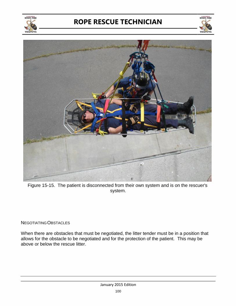
ROPE RESCUE TECHNICIAN
January 2015 Edition
100
Figure 15-15. The patient is disconnected from their own system and is on the rescuer's system.
NEGOTIATING OBSTACLES
When there are obstacles that must be negotiated, the litter tender must be in a position that allows for the obstacle to be negotiated and for the protection of the patient. This may be above or below the rescue litter.
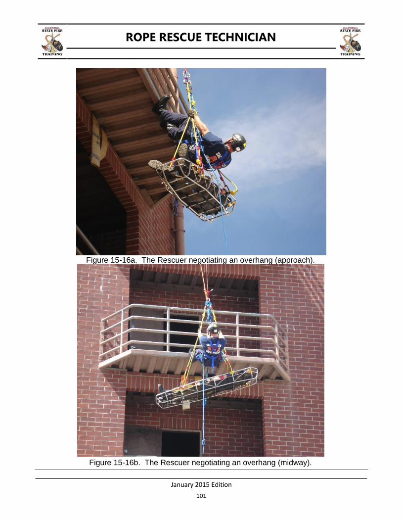
ROPE RESCUE TECHNICIAN
January 2015 Edition
101
Figure 15-16a. The Rescuer negotiating an overhang (approach).
Figure 15-16b. The Rescuer negotiating an overhang (midway).
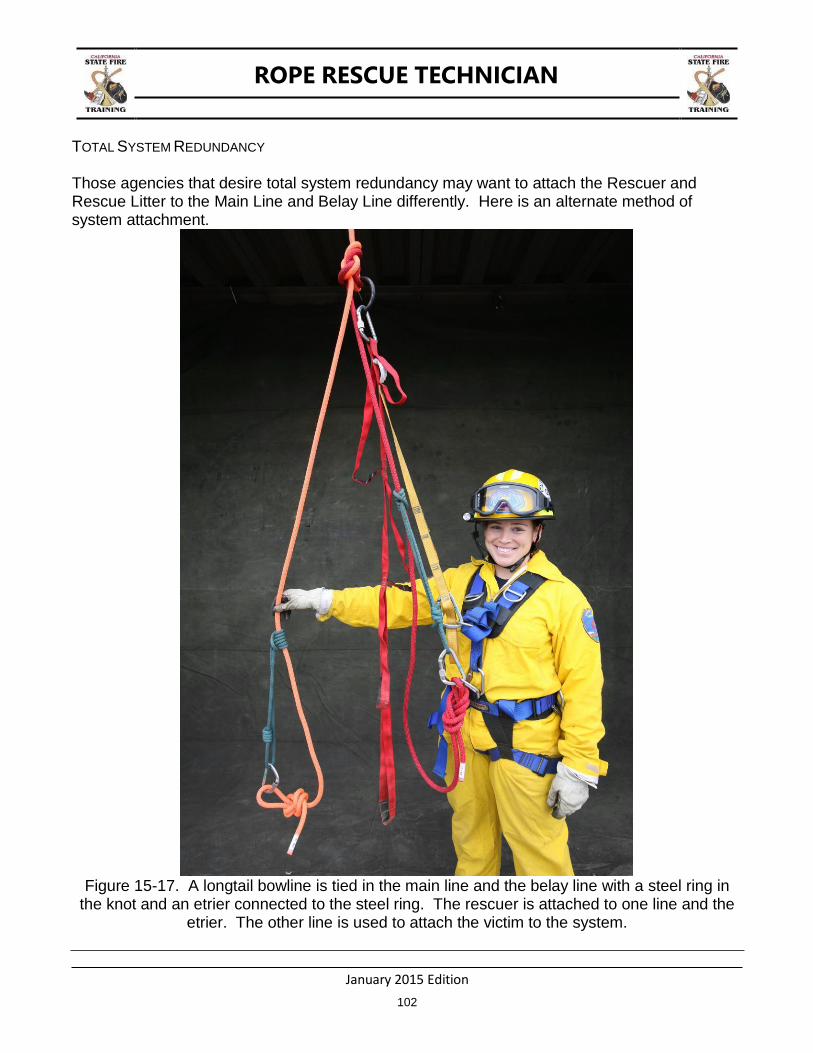
ROPE RESCUE TECHNICIAN
January 2015 Edition
102
TOTAL SYSTEM REDUNDANCY
Those agencies that desire total system redundancy may want to attach the Rescuer and Rescue Litter to the Main Line and Belay Line differently. Here is an alternate method of system attachment.
Figure 15-17. A longtail bowline is tied in the main line and the belay line with a steel ring in
the knot and an etrier connected to the steel ring. The rescuer is attached to one line and the etrier. The other line is used to attach the victim to the system.
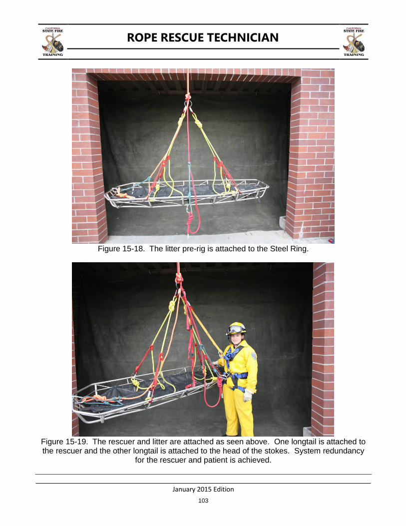
ROPE RESCUE TECHNICIAN
January 2015 Edition
103
Figure 15-18. The litter pre-rig is attached to the Steel Ring.
Figure 15-19. The rescuer and litter are attached as seen above. One longtail is attached to the rescuer and the other longtail is attached to the head of the stokes. System redundancy
for the rescuer and patient is achieved.
ROPE RESCUE TECHNICIAN
January 2015 Edition
104
THIS PAGE BLANK
ROPE RESCUE TECHNICIAN
January 2015 Edition
105
CHAPTER 16: ARTIFICIAL HIGH DIRECTIONALS
TERMINAL LEARNING OBJECTIVE
The student will construct and rig an artificial high directional.
ENABLING LEARNING OBJECTIVES
1. Construct an artificial high directional. 2. Rig a high directional.
Artificial High Directionals (AHDs) are constructed to assist the rescue team with edge transitions or any time the rescue team can benefit from having their ropes elevated above obstacles. In some situations a place to secure a high directional pulley may already exist. Examples of this include a tree limb, overhead structural components, or an improvised anchor. There a variety of high directional types and they can be categorized by the acronym H.A.N.S.
H – Human High Directional A – Artificial High Directional N – Natural High Directional S – Structural High Directional
Each of these high directionals has their own advantages and disadvantages. For example a pair of rescuers holding up a rope to create a highpoint is easily added but it is limited in lift height and the amount of time they can actually impart the needed lift. Conversely an Arizona Vortex fashioned as a floating “A” frame is very useful but can take time to construct.
The decision to use a high directional really is driven by two questions;
1. Is it needed? 2. Does the subject have the time to wait while one is constructed?
If the rescuer determines that a high directional is needed and the time to construct one is worth it, the rescuer should then determine what type to build.
HUMAN HIGH DIRECTIONALS
Human high directionals are the quickest to deploy but have limited use. A pair of rescuers holding a large pry bar can provide a quick high point to allow a rescuer to make a quick edge transition. In the low angle environment a pair of rescuers can hold a large bar under the main line to allow the litter team to safely transition the edge.
ROPE RESCUE TECHNICIAN
January 2015 Edition
106
ARTIFICIAL HIGH DIRECTIONALS
Artificial high directionals is a large category that includes such devices as tripods, davits, the Terradaptor™, the Arizona Vortex™, or lumber lashed into an improvised “A” frame. The focused floating anchor is also an AHD.
Figure 16-1. Artificial High Directional.
There are several commercial Artificial High Directionals on the market. The Arizona Vortex™ (AZV) is one of the more popular devices among rescue teams. NFPA 1983 classifies these as “portable anchor devices”. The AZV can be set up in any number of configurations from the simple tripod and easel “A” frame to the more advanced “A” frame, sideways “A” frame and gin pole or monopod.
ROPE RESCUE TECHNICIAN
January 2015 Edition
107
Whatever the configuration, the rescuer must understand the physics involved to ensure the AHD is loaded properly and will not fall over. The basic principle a rescuer must understand is called a “resultant force vector” or “resultant”. This is best visualized as a rope enters and exits a pulley. The rope on each side of the pulley has a force applied to it. The resultant can be visualized by drawing an imaginary line from the carabiner, through the axle of the pulley and terminating at the surface. This resultant determines where the force is applied and ultimately the “stability” of the AZV (or any other high directional).
Each variation of the AZV has a different requirement for the location of the resultant. For example, a tripod needs the resultant to be within the center of the three legs. The easel “A” frame allows the rescuer to move the resultant closer to the front legs. The more advanced applications of the AZV, such as the bipod (“A” frame) and monopod (gin pole) require the resultant to be straight down the legs. If, for some reason, the resultant does not go straight down the legs, the guy lines (and their anchors) take additional stress.
Safety Points of the AZV (and similar AHDs):
The AZV has a safe working load of 600 lbf (2.7kN).
Always ensure a belay line is used independent of the AZV (or any AHD).
The rescuer must ensure that all the feet are secured to prevent to spreading, uplifting or sideways forces.
Never couple more than 3 lower leg sections together on any one leg.
Attach a tether cord to the AZV when placing it.
The AZV is “G” rated (36kN) as a portable anchor device in the following 2 configurations:
1. Tripod (3 equal legs). This test was conducted using 1 upper leg with two lower legs and either flat or raptor feet. The legs were an equal distance apart and the upper legs were pinned to the head at the upper head pin hole and the last upper leg pin hole.
2. Easel – This test was conducted using 2 lower legs and one upper leg at max length for
the “A” frame section and three lower legs and one upper leg for the easel leg. The test was completed with the “A” frame section at 90 degrees relative to the ground with either flat or raptor feet.
NOTE: This manual is not intended to teach the rescuer everything about the AZV (or any
other AHD). It is very important that the rescuer obtain training from a recognized school of instruction when it comes to using any artificial high directional.
NATURAL HIGH DIRECTIONALS
Natural High Directionals are created by using rock outcroppings, limbs of trees, etc.

ROPE RESCUE TECHNICIAN
January 2015 Edition
108
STRUCTURAL HIGH DIRECTIONALS
Structural high directionals are those that are created by using parts of the structure to anchor your high point.
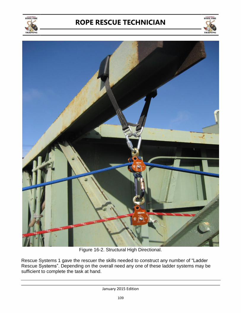
ROPE RESCUE TECHNICIAN
January 2015 Edition
109
Figure 16-2. Structural High Directional.
Rescue Systems 1 gave the rescuer the skills needed to construct any number of “Ladder Rescue Systems”. Depending on the overall need any one of these ladder systems may be sufficient to complete the task at hand.

ROPE RESCUE TECHNICIAN
January 2015 Edition
110
Regardless of the high directional chosen, the Rope Rescue Technician must take into account the potential resultant forces imparted on the high directional. This is determined by looking at the angle formed by the rope entering and leaving the high directional pulley. For example a rope that goes straight up, enters a change of direction pulley, and returns down to the starting point imparts a zero degree angle on the pulley. A zero degree pulley angle has a factor of 2. In other words a 200 pound load hanging on a rope that goes up, enters a pulley and returns to the ground next to the load requires 200 pounds of input force to lift the load. Once the load is off the ground gravity is exerted on the load. 200 pounds of input force plus the 200 pound load places 400 pounds on the high directional anchor.
A rope running through a pulley system at a 90 degree angle will magnify the load 1.41 times. So in the scenario noted above a 200 pound load running through a pulley at 90 degrees will place 282 pounds on the anchor supporting the pulley. Although 1.41 is the exact magnification for a 90 degree angle, it is common practice in the field to use 1.5 as the factor for ease in multiplication. It is also important to remember that these calculations are based on no friction. Friction will have an effect on the overall number but since each pulley and manufacturer have different construction techniques it is impossible to give one accurate number, hence the use of “frictionless” multipliers.
Figure 16-3. Magnification of load by the field angle. HOW TO CONSTRUCT A WOODEN “A” FRAME AS A FLOATING HIGH DIRECTIONAL
An artificial high directional can be constructed out of 4 x 4 or 6 x 6 timbers common in many Fire Department‘s Technical Rescue companies. The following is one way to construct an

ROPE RESCUE TECHNICIAN
January 2015 Edition
111
Artificial High Directional out of 12 foot long 4 x 4’s and 30 feet of ½ static or low stretch kernmantle rope.
Lay two 4 x 4’s side by side and prop one end up on top of another 4 x 4 allowing 360 degree access to each leg. Next insert a short 2 x 4 in between the legs so that the legs are separated approximately 1 ½ inches.
Figure 16-4. Starting an “A”-frame.
Using the ½ kernmantle rope make a clove hitch on one of the legs.
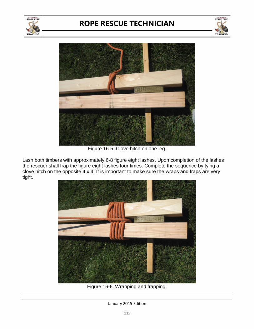
ROPE RESCUE TECHNICIAN
January 2015 Edition
112
Figure 16-5. Clove hitch on one leg.
Lash both timbers with approximately 6-8 figure eight lashes. Upon completion of the lashes the rescuer shall frap the figure eight lashes four times. Complete the sequence by tying a clove hitch on the opposite 4 x 4. It is important to make sure the wraps and fraps are very tight.
Figure 16-6. Wrapping and frapping.

ROPE RESCUE TECHNICIAN
January 2015 Edition
113
Figure 16-7. Secured with second clove hitch on opposite leg.
The next step is to construct the anchor that will support the pulley(s). Using either a 10 foot piece of kernmantle rope, cordelette, or webbing, wrap the ends in opposite directions until there are at least two loops. Secure the ends with a double overhand bend for rope or cordelette, or a water knot for webbing. Hang the pulley(s) from the anchor and stand up the “A” frame.
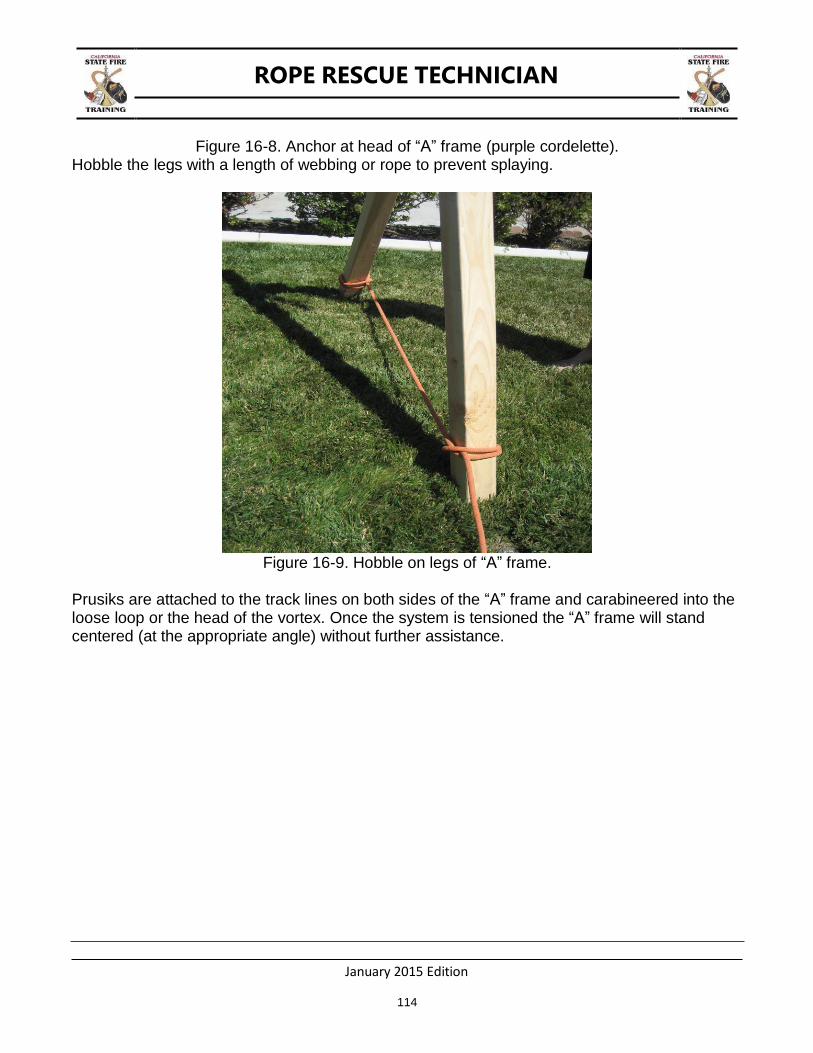
ROPE RESCUE TECHNICIAN
January 2015 Edition
114
Figure 16-8. Anchor at head of “A” frame (purple cordelette). Hobble the legs with a length of webbing or rope to prevent splaying.
Figure 16-9. Hobble on legs of “A” frame.
Prusiks are attached to the track lines on both sides of the “A” frame and carabineered into the loose loop or the head of the vortex. Once the system is tensioned the “A” frame will stand centered (at the appropriate angle) without further assistance.

ROPE RESCUE TECHNICIAN
January 2015 Edition
115
Figure 16-10. “A” frame centering prusiks (shown on AZV).
ROPE RESCUE TECHNICIAN
January 2015 Edition
116
THIS PAGE BLANK
ROPE RESCUE TECHNICIAN
January 2015 Edition
117
CHAPTER 17: HIGHLINES
TERMINAL LEARNING OBJECTIVE
The students will construct and operate a reeving highline with a midpoint drop to transport rescuers, equipment, and an occupied litter from one elevated location to another.
ENABLING LEARNING OBJECTIVES
1. Describe system safety factors, critical angles, and force multipliers. 2. Construct and operate a reeving highline system to perform a midpoint drop. 3. Move an occupied litter with an attendant from one elevated location to another above an
obstacle or projection.
INTRODUCTION
Most rope rescues are accomplished by lowering a rescuer from above, packaging the victim, and either lowering the rescue package down or raising the rescue package back up to an area for transport to a medical facility. These are known as vertical rescues. There may become a time, however, in which these vertical rescues will not work and the rescue must be completed in the horizontal realm. Highline systems can provide a solution to this problem. FIRESCOPE’s Urban Search and Rescue Operational System Description 120-1 defines a highline as “a system using rope suspended between two points for movement of persons or equipment over an area that is a barrier to the rescue operation, including systems capable of movement between points of equal or unequal height”.
Highline systems can be very dangerous due to the extreme forces these systems can generate. They require the Rope Rescue Technician to have a thorough understanding of force vectors, component uses and limitations, and require specialized training. An extensive system analysis should be performed before prior to using highline systems.
COMPONENTS AND TERMINOLOGY OF A HIGHLINE
Trackline(s) – The tracklines are the ropes that support the load. They span the gap between the two anchor points. Tracklines are usually tensioned using mechanical advantage systems.
Tagline – A tagline is used to control horizontal movement of the carriage system. The tagline acts as the system belay and, as such, should always have tandem prusiks.
Reeve Line – The reeveline is incorporated when the rescue team wants to add a vertical component to their highline. Reeve lines allow the rescue team to lower a rescuer to a victim without de-tensioning the trackline(s). Reeve Lines are either English or Norwegian.
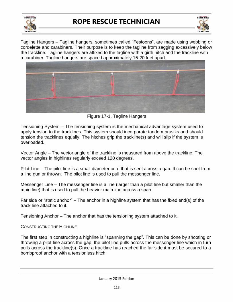
ROPE RESCUE TECHNICIAN
January 2015 Edition
118
Tagline Hangers – Tagline hangers, sometimes called “Festoons”, are made using webbing or cordelette and carabiners. Their purpose is to keep the tagline from sagging excessively below the trackline. Tagline hangers are affixed to the tagline with a girth hitch and the trackline with a carabiner. Tagline hangers are spaced approximately 15-20 feet apart.
Figure 17-1. Tagline Hangers
Tensioning System – The tensioning system is the mechanical advantage system used to apply tension to the tracklines. This system should incorporate tandem prusiks and should tension the tracklines equally. The hitches grip the trackline(s) and will slip if the system is overloaded.
Vector Angle – The vector angle of the trackline is measured from above the trackline. The vector angles in highlines regularly exceed 120 degrees.
Pilot Line – The pilot line is a small diameter cord that is sent across a gap. It can be shot from a line gun or thrown. The pilot line is used to pull the messenger line.
Messenger Line – The messenger line is a line (larger than a pilot line but smaller than the main line) that is used to pull the heavier main line across a span.
Far side or “static anchor” – The anchor in a highline system that has the fixed end(s) of the track line attached to it.
Tensioning Anchor – The anchor that has the tensioning system attached to it.
CONSTRUCTING THE HIGHLINE
The first step in constructing a highline is “spanning the gap”. This can be done by shooting or throwing a pilot line across the gap, the pilot line pulls across the messenger line which in turn pulls across the trackline(s). Once a trackline has reached the far side it must be secured to a bombproof anchor with a tensionless hitch.

ROPE RESCUE TECHNICIAN
January 2015 Edition
119
The next step will be to determine if a high directional is needed near the edge. A high directional is employed whenever the tracklines need to be elevated higher than the anchor systems will allow. High directionals may be needed at the far side and the control side depending on the how you are designing your system to operate. There a variety of high directional types and they can be categorized by the acronym H.A.N.S.
H – Human High Directional – rescuers holding a “jumbo bar” or other device under the ropes to provide a temporary high point while a rescuer negotiates an edge.
A – Artificial High Directional – an Arizona Vortex, Terradaptor, or 6 x 6 lumber constructed into an “A” frame. A focused floating anchor is also categorized as an AHD.
N – Natural High Directional – using trees, boulders, etc to keep the ropes at the correct height.
S – Structural High Directional – using parts of a structure as an anchor to create a high point.
Figure 17-2. A Structural High Directional
After constructing the High Directional, the trackline tensioning system needs to be constructed. Before building this system it must be understood what makes highlines so dangerous. Due to the angles created in highline systems, the force on the anchors typically exceeds that of the load. Students are always instructed to never exceed a 90 degree internal

ROPE RESCUE TECHNICIAN
January 2015 Edition
120
angle when creating anchor systems. A 90 degree internal angle will place approximately 71% of the load on each anchor. Think of the trackline as an anchor with a very wide angle. It is not uncommon for a trackline to be tensioned creating an internal angle greater than 150 degrees. From previous anchor lectures, an internal angle of 120 degrees has the weight of the load on each anchor. Once 120 degrees is exceeded, the forces on the anchors are greater than the load. For example, a vector angle of 150 degrees places almost 2 times the load on each anchor. A vector angle of 170 degrees places almost 6 times the load on each anchor.
In order to avoid over tensioning the highline system, refer to the “Rule of 18”. This rule, which applies to 12.5 mm (1/2 inch) rope, simply states that the number of haulers multiplied by the mechanical advantage of the tensioning system should not exceed 18 with the load at center span. For example; a compound 6:1 mechanical advantage can have no more than 3 haulers (6 x 3 = 18). Using this rule will ensure that the tensioning team does not over tension the highline.
There are many types of highlines. The simplest is a single track line with a 3:1 tensioning system. This system is very quick to construct and incorporates many skills taught in LARRO and RS1. The major difference is that the “ratchet” uses tandem prusiks, instead of a single prusik used in most raising systems.
Figure 17-3. Tandem Prusiks holding on a 3:1 used as a highline
Single track highlines are easy to construct and operate. Sag is created by de-tensioning the track line thus lowering the total force on the trackline anchors. There are scenarios, however, where excessive sag is not wanted (i.e. swiftwater rescue). This problem is solved by adding a second track line.
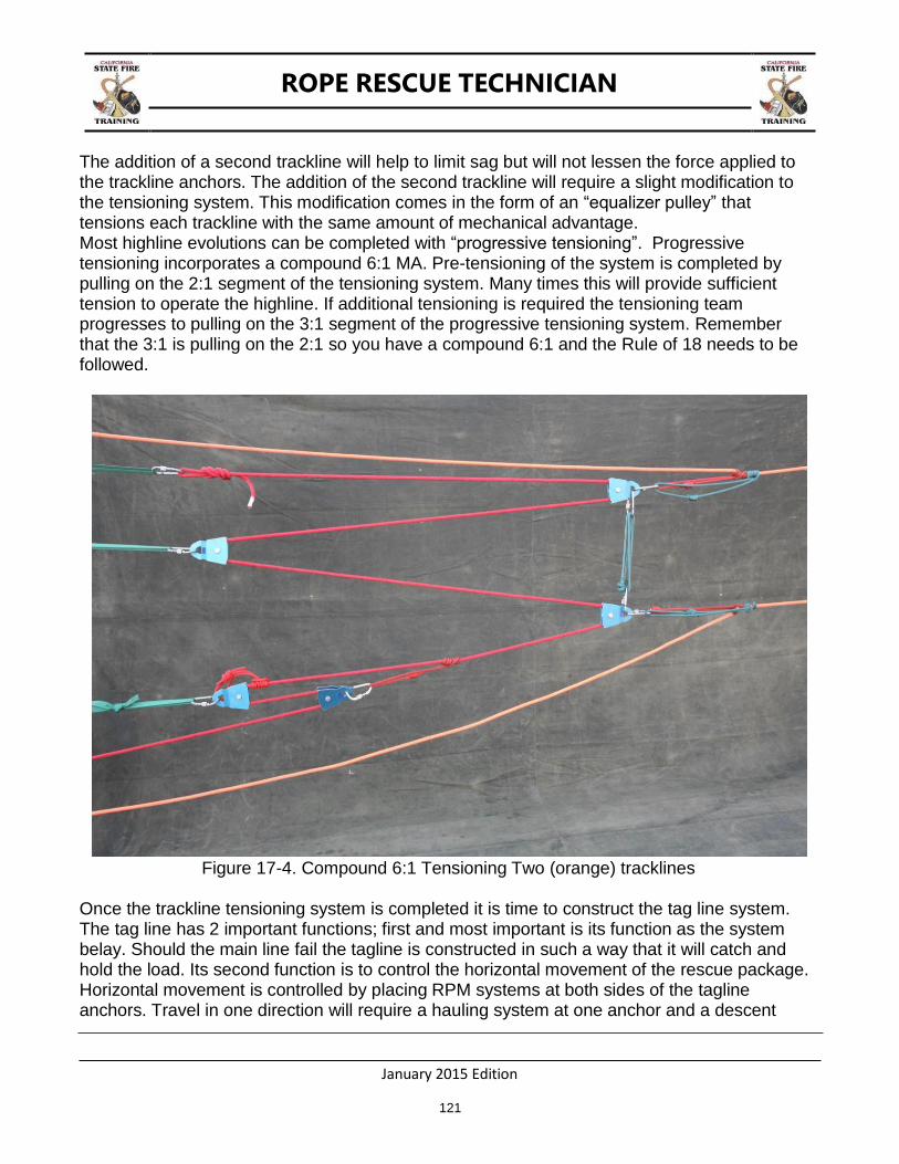
ROPE RESCUE TECHNICIAN
January 2015 Edition
121
The addition of a second trackline will help to limit sag but will not lessen the force applied to the trackline anchors. The addition of the second trackline will require a slight modification to the tensioning system. This modification comes in the form of an “equalizer pulley” that tensions each trackline with the same amount of mechanical advantage. Most highline evolutions can be completed with “progressive tensioning”. Progressive tensioning incorporates a compound 6:1 MA. Pre-tensioning of the system is completed by pulling on the 2:1 segment of the tensioning system. Many times this will provide sufficient tension to operate the highline. If additional tensioning is required the tensioning team progresses to pulling on the 3:1 segment of the progressive tensioning system. Remember that the 3:1 is pulling on the 2:1 so you have a compound 6:1 and the Rule of 18 needs to be followed.
Figure 17-4. Compound 6:1 Tensioning Two (orange) tracklines
Once the trackline tensioning system is completed it is time to construct the tag line system. The tag line has 2 important functions; first and most important is its function as the system belay. Should the main line fail the tagline is constructed in such a way that it will catch and hold the load. Its second function is to control the horizontal movement of the rescue package. Horizontal movement is controlled by placing RPM systems at both sides of the tagline anchors. Travel in one direction will require a hauling system at one anchor and a descent
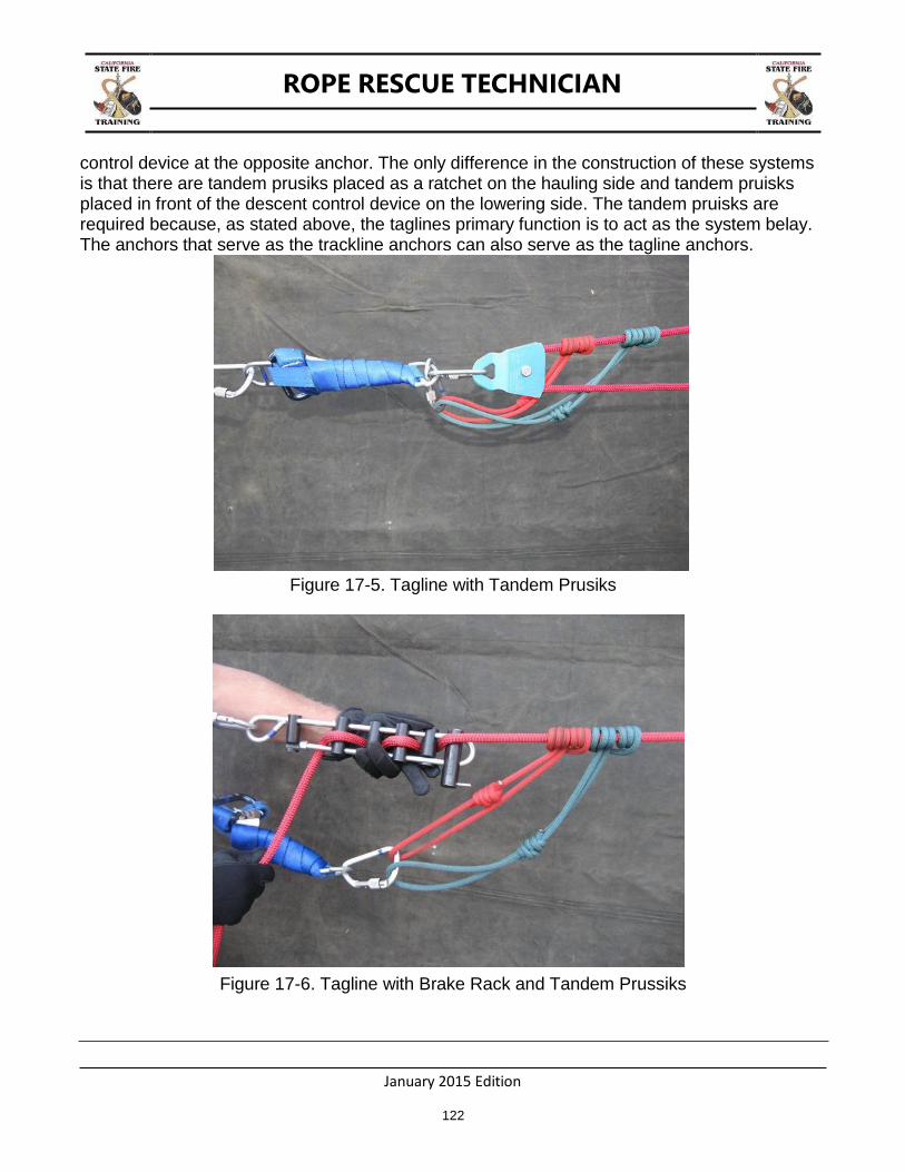
ROPE RESCUE TECHNICIAN
January 2015 Edition
122
control device at the opposite anchor. The only difference in the construction of these systems is that there are tandem prusiks placed as a ratchet on the hauling side and tandem pruisks placed in front of the descent control device on the lowering side. The tandem pruisks are required because, as stated above, the taglines primary function is to act as the system belay. The anchors that serve as the trackline anchors can also serve as the tagline anchors.
Figure 17-5. Tagline with Tandem Prusiks
Figure 17-6. Tagline with Brake Rack and Tandem Prussiks

ROPE RESCUE TECHNICIAN
January 2015 Edition
123
The load is attached to the trackline(s) with a pulley. The pulley type best suited for this application is a highline carriage. What makes these pulleys so advantageous is that they are designed to be used for this purpose. Their key feature is extra rigging holes which allow for separation of taglines and hoist lines when constructing a reeving highline. The tagline(s) is/are attached to the highline carriage with a “prusik bypass”. The “slack” ends of the taglines run through the carabiners that are attached to the highline carriage.
Figure 17-7. Highline Carriage with Stokes Basket
When the rescue team constructs a highline they have an option of using one or two highline carriages based on the ultimate use of the system. For example, if a litter is being used to transport persons horizontally then the rescue team may want to employ a dual carriage system to prevent any spinning of the litter during transport. Spinning can also be resolved by attaching a piece of webbing to the head and/or foot of the litter and clipping the other end over the trackline(s), much like a tagline hanger.
For horizontal movement only, the highline is complete. The “load” is hung from the tracklines by a highline carriage and pulled across the span by using the 3:1 on one side of the tagline and lowering, thru a brake bar rack, on the other side. Remember that these systems employ

ROPE RESCUE TECHNICIAN
January 2015 Edition
124
tandem prusiks at the ratchet position, or in the case of lowering, in front of the brake bar rack. This type of highline can also be “de-tensioned”, by lowering on the mechanical advantage system. The ability to de-tension this highline is dependent on the angle of the edge and the distance the trackline must be lowered. The terrain in some scenarios will not allow the rescue team to de-tension the highline enough so that the rescuer can reach the intended target. Situations like that require the rescue team to add a third component to highline called a reeving line.
A reeving line allows the trackline to remain tensioned while lowering the rescuer. There are two types of reeves; English or Norwegian. They both incorporate a lowering component and a raising component. The Norwegian reeve uses a 6:1 compound mechanical advantage system to raise the rescue package from the floor of the span being traversed. A Norwegian reeve is worked from one side while an English reeve can be worked from either side. An English reeve is more equipment intensive than a Norwegian reeve.
A Norwegian reeve line is constructed by tying one end of the reeve line into a figure eight on a bight and clipping it into the bottom of the highline carriage which is hanging from the trackline(s). A pulley is attached in the bight forming a 2:1 mechanical advantage. A change of direction pulley is also placed on the highline carriage. The rope then continues to the control side and terminates at an RPM.
The pulley forming the 2:1 mechanical advantage should have a pruisk placed on both sides of the pulley. One prusik is tended while the rescue package is being lowered and then other is tended when the rescue package is being raised. The use of 2 prusiks ensures that the load on the reeve line has two points of contact.
An English reeve is similar to a Norwegian reeve with the main difference being that the reeve line begins on one side and terminates on the other side. This system is operated similar to a highline without a reeve line. The rescue package is pulled across the span using the tag lines. Once the rescuer is above the intended target, the tag line is secured and the control side team lowers the reeve line.

ROPE RESCUE TECHNICIAN
January 2015 Edition
125
Figure 17-8. 2:1 Portion of a Norwegian Reeve
HIGHLINE RULES
1. Due to the extreme forces generated all anchors must be bombproof.
2. There should be no knots in the trackline ropes.
3. Knots in the tagline shall have a prusik bypass.
4. Load carrying prusiks on the tracklines and tag lines shall be tandem.
5. Never exceed the “Rule of 18” tensioning factor for 12.5 mm rope.
6. Ensure the device you use to hang loads from the trackline are rated for multi directional
use.
ROPE RESCUE TECHNICIAN
January 2015 Edition
126
THIS PAGE BLANK
ROPE RESCUE TECHNICIAN
January 2015 Edition
127
GLOSSARY
Ambulatory Victim A victim that is capable of walking.
Anchor An object that rope or webbing can be attached to capable of holding a load. The object may be manmade or natural.
Anchor Plate A component of rope rescue hardware intended to help organize
anchor and system component rigging.
Belay The method by which a potential fall distance is controlled to minimize damage to equipment and/or injury to a live load. Usually constructed as part of rope system.
Bending knot A knot used to tie rope or webbing into itself to form a continuous
loop, or to join two lengths of material together to extend the length. Also referred to as a “Bend”.
Bight The open loop in a rope or piece of webbing formed when it is
doubled back on itself.
Brake Tool used to create friction to slow rope descent.
Bridle See pre-rig.
Bollard A round, non-trussed anchor.
Cam An eccentric or multi curved wheel mounted on a rotating shaft, used to produce variable or reciprocating motion in another engaged or contacted part.
Carabiner An auxiliary equipment system component; an oval or D-shaped
metal, load-bearing connector with a self-closing gate used to join other components of a rope system.
Class II Victim Device A device that secures around the waist and around the thighs or
under the buttocks to be used for victim extrication in an upright position.
Class III Victim Device A device that secures around the waist, around the thighs, or under
the buttocks, and over the shoulders or that otherwise encapsulates a body to be used for victim extrication in an upright or horizontal configuration.
ROPE RESCUE TECHNICIAN
January 2015 Edition
128
Cordelette A narrow diameter line, usually 9mm or smaller.
Descender A device used to create friction to control the movement or descent of the rope.
Detensioning Releasing the load from a tensioned line.
Dressed A knot constructed in a uniform manner free of any twists or abnormalities.
Fixed Line A suitably anchored rope used for rappelling or ascending.
Festoons Small loops made using webbing or prusiks and carabiners. Their purpose is to keep the Tag Line from sagging excessively below the track Line. Tagline hangers are affixed to the Tagline with a girth hitch and the Track Line with a carabiner. Tagline hangers are spaced approximately 15-20 feet apart.
Friction Device See descender.
Hitch A knot that attaches to, or wraps around, an object so that when the
object is removed the knot will fall apart.
Kern Continuous parallel fibers throughout the length of the rope, forming its core. The Kern accounts for 75-90% of the rope's breaking strength.
Kernmantle Rescue Rope Rope consisting of a core (kern) and a sheath (mantle) that is the
primary tool for raising and lowering rescuers, equipment, and victims.
Knot A fastening, including bights, bends, and hitches, made by tying
together lengths of rope or webbing in a prescribed way.
Lifeline Rope dedicated solely for the purpose of supporting people during rescue, fire fighting, other emergency operations, or during training evolutions.
Litter A transfer device designed to support and protect a victim during
movement.
Load Releasing Hitch Tied device constructed of cordelette, rope or webbing and
hardware, designed to provide a controlled release under tension and to decrease shock loads. Also referred to as an LRH.
ROPE RESCUE TECHNICIAN
January 2015 Edition
129
Load Releasing Device Premanufactured device constructed of flat webbing and D-rings designed to provide a controlled release under tension and to decrease shock loads. Also referred to as an LRD.
Lock-off A means to secure a descending device to prevent further
movement down rope.
Loop An element of a knot created by forming a complete circle in the rope.
Mantle The braided jacket that forms the rope's sheath and protects it core (kern); the mantle accounts for 10-25% of the rope's breaking strength.
Messenger Line A line that is larger than a pilot line but smaller than a track line.
Commonly used to pull a tag line or track line across a gap.
Picket Metal rods usually 1” in diameter and 4 feet long that can be driven into the ground to create a temporary anchor for a rope system.
Pilot Line A small diameter cord that is sent across a gap and is used to pull a larger diameter line across the gap. Commonly used to pull a Messenger Line.
Pre-rig An adjustable pre-tied combination of lifeline, prusiks, and
carabiners used to connect the rescue lines, litter, and rescuers together.
Prusik (prusik loop) Narrow kernmantle rope, usually 8 mm in diameter, tied with a
double overhand bend. Adapted for rescue work as a rope grab to perform many different functions.
Prusik Hitch The knot used for attaching the prusik loop to the host rope.
Rappel A slow, controlled, decent down a fixed line.
Reeve To pass a rope through a hole, ring, pulley, or block. To fasten by passing through or around.
Running End Part of the rope that "runs" away from the knot.
Round Turn An element of a knot created from a loop by continuing to cross one
side of the loop all the way around an object to form a circle with the ends of the rope parallel as in a bight.
ROPE RESCUE TECHNICIAN
January 2015 Edition
130
Scree 1) Loose rock debris covering a slope. 2) A slope of loose rock debris at the base of a steep incline or cliff.
Set Setting a knot means applying tension to all strands of the standing portion of the rope and on the tail left on either side of the knot. This removes any slack from the strands forming the knot.
Set back The distance between the edge and the anchoring apparatus.
Sheave A wheel or disk with a grooved rim, especially one used as a pulley.
Standing Part Part of the rope between running end and working end.
Stokes Basket Another term for a rescue litter or litter basket.
Tag Line 1) Varying lengths of lifeline or webbing used to extend anchors in a tagged anchor system. 2) An additional line used to control motion elsewhere in a system such as on a basket in mid-air.
Training Groove The notch or depression found in the top bar of a brake bar rack.
Two Block A condition that occurs when two or more pulleys come together or
come into contact and cause the system to become inoperable.
US&R Urban search and rescue.
Vector Pull Providing deflection in a rope by applying force to the rope perpendicular to the direction of the load.
Webbing Woven material in the form of a long strip; can be of flat or tubular
weave.
Windlass The technique of connecting pickets in a windlassed picket system to each other with shorter lengths of lifeline or webbing.
WMD Weapons of mass destruction.
Working end Part of the rope used in forming a knot. (Also known as "loose end"
or "bitter end.").

ROPE RESCUE TECHNICIAN
January 2015 Edition
APP E NDIX A
TASK BOOKS
All Rope Rescue Task Books can be found on the SFT Website at:
http://osfm.fire.ca.gov/training/SFTCurriculum
ROPE RESCUE TECHNICIAN
January 2015 Edition
APP E NDIX B
EVENT ACTION PLAN

CALIFORNIA ROPE RESCUE TECHNICIAN
COURSE
ROPE RESCUE TECHNICIAN
OPERATIONAL PERIOD
X/XX/XXXX – X/XX/XXXX
0800 – 1700 HOURS
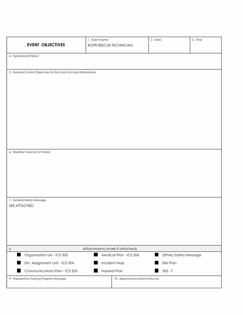
EVENT OBJECTIVES
1. Event Name
ROPE RESCUE TECHNICIAN
2. Date 3. Time
4. Operational Period
5. General Control Objectives for the Event (include alternatives)
6. Weather Forecast for Period
7. General Safety Message
SEE ATTACHED
8. Attachments (mark if attached)
Organization List - ICS 203 Medical Plan - ICS 206 (0ther) Safety Message
Div. Assignment Lists - ICS 204 Incident Map Site Plan
Communications Plan - ICS 205 HazMat Plan 205 - T
9. Prepared by Training Program Manager 10. Approved by Senior Instructor

POSITION NAME SUBJECT
SENIOR INSTRUCTOR
PRIMARY INSTRUCTOR
SAFETY OFFICER
INSTRUCTOR
INSTRUCTOR
INSTRUCTOR
INSTRUCTOR
INSTRUCTOR
INSTRUCTOR
INSTRUCTOR
INSTRUCTOR
INSTRUCTOR
COURSE MANAGER

1. BRANCH 2. DIVISION/GROUP
DAY 1
ASSIGNMENT LIST
3. EVENT NAME
ROPE RESCUE TECHNICIAN
4. OPERATIONAL PERIOD
5. OPERATIONS PERSONNEL
6. RESOURCES ASSIGNED THIS PERIOD
SUBJECT INSTRUCTOR NUMBER
PERSONS
TRANS.
NEEDED
DROP OFF
PT./TIME
PICK UP
PT./TIME
7. CONTROL OPERATIONS
8. SPECIAL INSTRUCTIONS
9. DIVISION/GROUP COMMUNICATIONS SUMMARY
FUNCTION FREQ. SYSTEM CHAN FUNCTION FREQ. SYSTEM CHAN.
PREPARED BY TRAINING PROGRAM MANAGER: APPROVED BY SENIOR INSTRUCTOR: DATE: TIME
ICS 204

ICS 204
1. BRANCH 2. DIVISION/GROUP
DAY 2
ASSIGNMENT LIST
3. EVENT NAME
ROPE RESCUE TECHNICIAN
4. OPERATIONAL PERIOD
5. OPERATIONS PERSONNEL
6. RESOURCES ASSIGNED THIS PERIOD
SUBJECT INSTRUCTOR NUMBER
PERSONS
TRANS.
NEEDED
DROP OFF
PT./TIME
PICK UP
PT./TIME
7. CONTROL OPERATIONS
8. SPECIAL INSTRUCTIONS
9. DIVISION/GROUP COMMUNICATIONS SUMMARY
FUNCTION FREQ. SYSTEM CHAN FUNCTION FREQ. SYSTEM CHAN.
PREPARED BY TRAINING PROGRAM MANAGER: APPROVED BY SENIOR INSTRUCTOR: DATE: TIME

ICS 204
1. BRANCH 2. DIVISION/GROUP
DAY 3
ASSIGNMENT LIST
3. EVENT NAME
ROPE RESCUE TECHNICIAN
4. OPERATIONAL PERIOD
5. OPERATIONS PERSONNEL
6. RESOURCES ASSIGNED THIS PERIOD
SUBJECT INSTRUCTOR NUMBER
PERSONS
TRANS.
NEEDED
DROP OFF
PT./TIME
PICK UP
PT./TIME
7. CONTROL OPERATIONS
8. SPECIAL INSTRUCTIONS
9. DIVISION/GROUP COMMUNICATIONS SUMMARY
FUNCTION FREQ. SYSTEM CHAN FUNCTION FREQ. SYSTEM CHAN.
PREPARED BY TRAINING PROGRAM MANAGER: APPROVED BY SENIOR INSTRUCTOR: DATE: TIME

ICS 204
1. BRANCH 2. DIVISION/GROUP
DAY 4
ASSIGNMENT LIST
3. EVENT NAME
ROPE RESCUE TECHNICIAN
4. OPERATIONAL PERIOD
5. OPERATIONS PERSONNEL
6. RESOURCES ASSIGNED THIS PERIOD
SUBJECT INSTRUCTOR NUMBER
PERSONS
TRANS.
NEEDED
DROP OFF
PT./TIME
PICK UP
PT./TIME
7. CONTROL OPERATIONS
8. SPECIAL INSTRUCTIONS
9. DIVISION/GROUP COMMUNICATIONS SUMMARY
FUNCTION FREQ. SYSTEM CHAN FUNCTION FREQ. SYSTEM CHAN.
PREPARED BY TRAINING PROGRAM MANAGER: APPROVED BY SENIOR INSTRUCTOR: DATE: TIME

ICS 204
1. BRANCH 2. DIVISION/GROUP
DAY 5
ASSIGNMENT LIST
3. EVENT NAME
ROPE RESCUE TECHNICIAN
4. OPERATIONAL PERIOD
5. OPERATIONS PERSONNEL
6. RESOURCES ASSIGNED THIS PERIOD
SUBJECT INSTRUCTOR NUMBER
PERSONS
TRANS.
NEEDED
DROP OFF
PT./TIME
PICK UP
PT./TIME
7. CONTROL OPERATIONS
8. SPECIAL INSTRUCTIONS
9. DIVISION/GROUP COMMUNICATIONS SUMMARY
FUNCTION FREQ. SYSTEM CHAN FUNCTION FREQ. SYSTEM CHAN.
PREPARED BY TRAINING PROGRAM MANAGER: APPROVED BY SENIOR INSTRUCTOR: DATE: TIME

SAFETY OFFICER:

EVENT RADIO COMMUNICATIONS PLAN
1. Event Name
ROPE RESCUE TECHNICIAN
2. Date/Time Prepared 3. Operational Period Date/Time
4. Basic Radio Channel Utilization
Radio Type/Cache Channel Name Function Frequency/Tone Assignment Remarks
5. Prepared by TRAINING PROGRAM MANAGER

TELEPHONE LIST
INSTRUCTOR POSITION CELL NUMBER
205T

MEDICAL PLAN
1. Event Name
ROPE RESCUE
TECHNICIAN
2. Date Prepared 3. Time Prepared 4. Operational Period
5. Event Medical Aid Station
Medical Aid Stations
Location Paramedics
Yes No
6. Transportation
A. Ambulance Services
Name
Address
Phone Paramedics
Yes No
B. Event Ambulances
Name
Location Paramedics
Yes No
7. Hospitals
Name
Address Travel Time Air Ground
Phone Helipad Yes No
Burn Center Yes No
8. Medical Emergency Procedures
Prepared by TRAINING PROGRAM MANAGER: 10. Reviewed by SAFETY OFFICER:

XX/XX/XXXX
TRAINING SITE 1

XX/XX/XXXX
TRAINING SITE 2
ROPE RESCUE TECHNICIAN
APP E NDIX C
USE OF ROPE ACCESS EQUIPMENT (CCR 3270.1)
January 2015 Edition
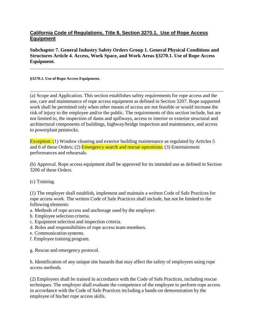
California Code of Regulations, Title 8, Section 3270.1. Use of Rope Access Equipment
Subchapter 7. General Industry Safety Orders Group 1. General Physical Conditions and
Structures Article 4. Access, Work Space, and Work Areas §3270.1. Use of Rope Access
Equipment.
§3270.1. Use of Rope Access Equipment.
(a) Scope and Application. This section establishes safety requirements for rope access and the
use, care and maintenance of rope access equipment as defined in Section 3207. Rope supported
work shall be permitted only when other means of access are not feasible or would increase the
risk of injury to the employee and/or the public. The requirements of this section include, but are
not limited to, the inspection of dams and spillways, access to interior or exterior structural and
architectural components of buildings, highway/bridge inspection and maintenance, and access
to powerplant penstocks.
Exception: (1) Window cleaning and exterior building maintenance as regulated by Articles 5
and 6 of these Orders; (2) Emergency search and rescue operations; (3) Entertainment
performances and rehearsals.
(b) Approval. Rope access equipment shall be approved for its intended use as defined in Section
3206 of these Orders.
(c) Training.
(1) The employer shall establish, implement and maintain a written Code of Safe Practices for
rope access work. The written Code of Safe Practices shall include, but not be limited to the
following elements:
a. Methods of rope access and anchorage used by the employer.
b. Employee selection criteria.
c. Equipment selection and inspection criteria.
d. Roles and responsibilities of rope access team members.
e. Communication systems.
f. Employee training program.
g. Rescue and emergency protocol.
h. Identification of any unique site hazards that may affect the safety of employees using rope
access methods.
(2) Employees shall be trained in accordance with the Code of Safe Practices, including rescue
techniques. The employer shall evaluate the competence of the employee to perform rope access
in accordance with the Code of Safe Practices including a hands-on demonstration by the
employee of his/her rope access skills.

(3) Employees who perform rope access shall receive annual refresher training. The training
shall include a reevaluation (e.g., hands-on demonstration) of the employee's ability to perform
rope access in accordance with the Code of Safe Practices.
(4) Documentation of employee training shall be maintained as required by Section 3203 of these
Orders.
(d) Equipment Inspection and Maintenance.
(2) A qualified person shall inspect rope access equipment each day before and after use to
determine that the equipment is safe for its intended use.
(3) Damaged or defective rope access equipment shall be immediately removed from service.
(g) There shall be at least two trained employees present when rope access equipment and
techniques are used.
(h) Trainer Qualifications. Employees who use rope access equipment and/or perform rope
access shall be trained by persons with the qualifications and experience necessary to effectively
instruct the employee in the proper fundamentals of rope access, equipment, and techniques as
described in subsection (c) of this section.
(i) The employer shall provide for the prompt rescue of employees in case of equipment
malfunction or a fall, or shall assure that employees are able to rescue themselves.
(k) Precautions (e.g., barricades, warning lines) shall be taken to control vehicular traffic and/or
prevent unauthorized persons from walking or working beneath employees performing rope
access operations.
(1) When a safety line is used in conjunction with the main line, each line shall be provided with
a separate anchor, and shall be separately fixed to the employee's harness. This shall not prohibit
both lines from being attached to a single harness attachment point.
(j) A safety, secondary, belay, or backup line, or other appropriate fall arrest device shall be used
when the main line is the primary means of support, unless the employer can demonstrate that
the second line or other fall arrest device would create a greater hazard or would otherwise be
infeasible.
(f) Personal Protective Equipment. Employees performing rope access work shall be provided
personal protective equipment in accordance with Article 10 of these Orders.
(e) Anchorage. Anchorages shall be sufficient to safety support at least twice the maximum
anticipated dynamic load imposed upon them as determined by a qualified person.
(1) The manufacturer's recommendations for use, care, inspection and maintenance of rope
access equipment shall be followed.
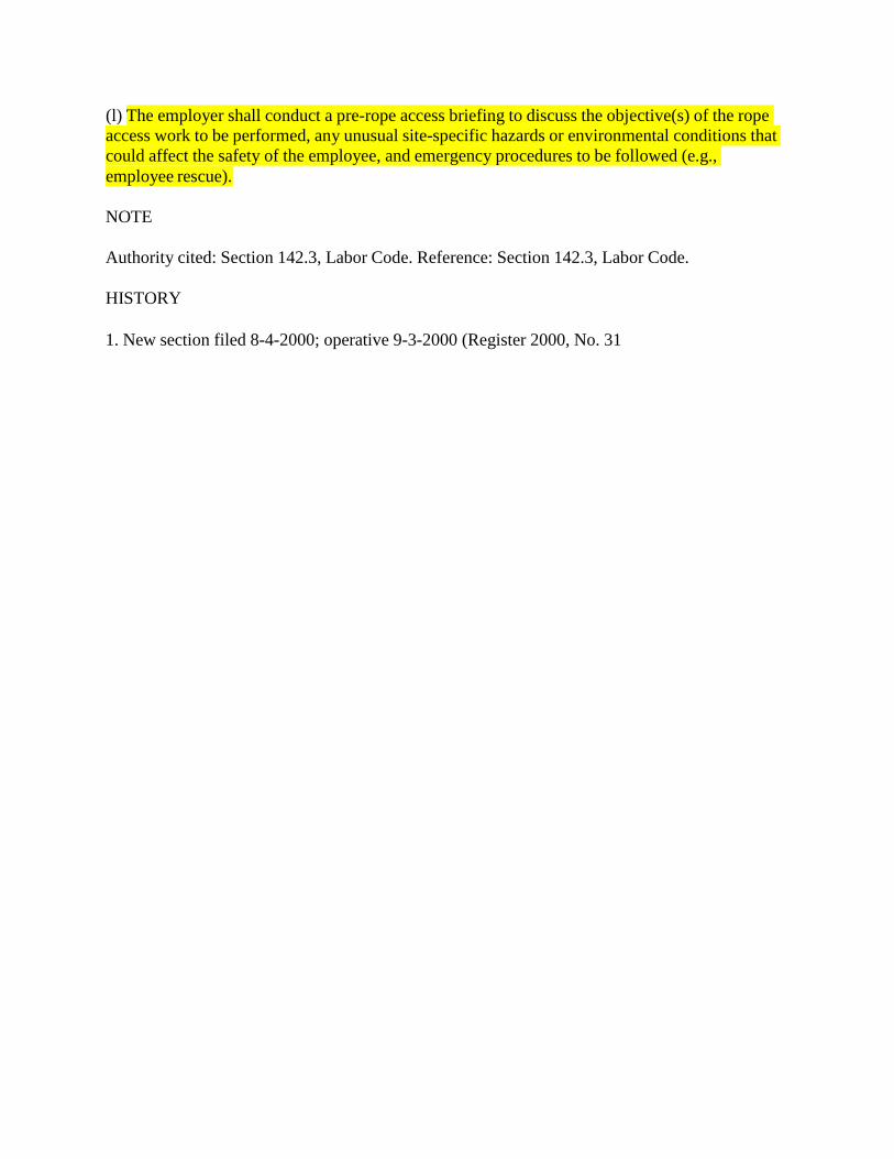
NOTE
Authority cited: Section 142.3, Labor Code. Reference: Section 142.3, Labor Code.
HISTORY
1. New section filed 8-4-2000; operative 9-3-2000 (Register 2000, No. 31
(l) The employer shall conduct a pre-rope access briefing to discuss the objective(s) of the rope
access work to be performed, any unusual site-specific hazards or environmental conditions that
could affect the safety of the employee, and emergency procedures to be followed (e.g.,
employee rescue).

ROPE RESCUE TECHNICIAN
APP E NDIX D
POWERPOINT
January 2015 Edition
All Rescuers operating at the technician level in CA.
3. The State Training system NFPA are built around Three levels Awareness, Operations Technician

All Rescuers operating at the technician level in CA.
3. The State Training system NFPA are built around
Three levels Awareness, Operations Technician
4. 2009 Approached Joe Gear about the need for a
technician rope class for with the Blessing of Kim
Zagaris we convened in June 2010

4
Rope Rescue Technician
Funding Source Secured
i
Joe Gear Cal OES Assistant Chief in
Charge of US&R was Approached
and Made Aware of Training Deficit
With Approv a l From Kim Zagar is Cal
OES Fire and Rescue Ch e f a
Funding S our c e was I de ntifie d

5
ROPE RESCUE TECHNICIAN
• FIRESCOPE Type 1 US&R Companies
• FIRESCOPE Type 1 US&R Crews
• Regiona l US&R Task Forces
• California US&R Task Forces
• F EMA US&R Task Forces
• All Califor ni a Resc uers
Affects the Following Resources
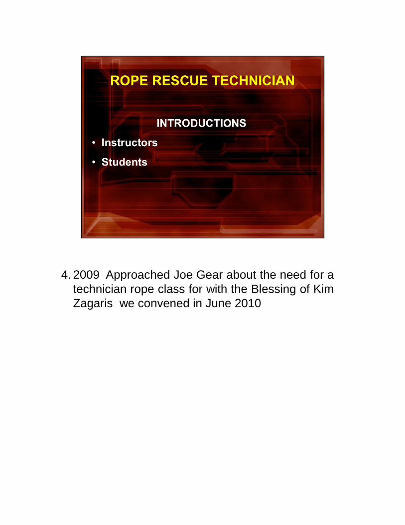
4. 2009 Approached Joe Gear about the need for a
technician rope class for with the Blessing of Kim
Zagaris we convened in June 2010
7
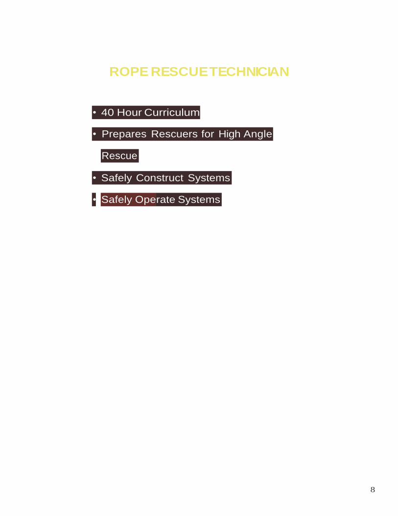
8
ROPE RESCUE TECHNICIAN
•
• Safely Construct Systems
Rescue
• Prepares Rescuers for High Angle
• 40 Hour Curriculum
Safely Operate Systems
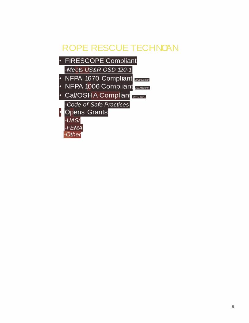
9
ROPE RESCUE TECHNICIAN
2009 Edition
• FIRESCOPE Compliant
-Meets US&R OSD 120-1
• NFPA 1670 Compliant
• NFPA 1006 Compliant 201J Edition
• Cal/OSHA Compliant ccR J210.1
-Code of Safe Practices
• Opens Grants
-UAS/
-FEMA -Other
Following are the skills that are not currently in any
State Fire Class and are necessary to reach the
technician level
All Skills in the class meet the requirements in 1670
Technician &1006 level I & II skill sets
ROPE RESCUE TECHNICIAN
11
on
6 . Travel Restri cti
.
8. Mainline Systems
7. Belay Systems
5. High Angle Victim Packaging
Systems Anchor 4.
Knots, Bends, and Hitches 3.
Rope Rescue Equipment 2.
1. Course Introduction
9. Load Releasing Methods
CHAPTERS
ROPE RESCUE TECHNICIAN
12
17. Highlines
16. Artificial High Directionals
High Angle Litter Rigging and Tending 15.
14. Protected Climbing
13. Pick Offs
12. Ascendi ng and Descending
11. Knot Passing
10. Rescue Scene Organization and Management
CHAPTERS
13
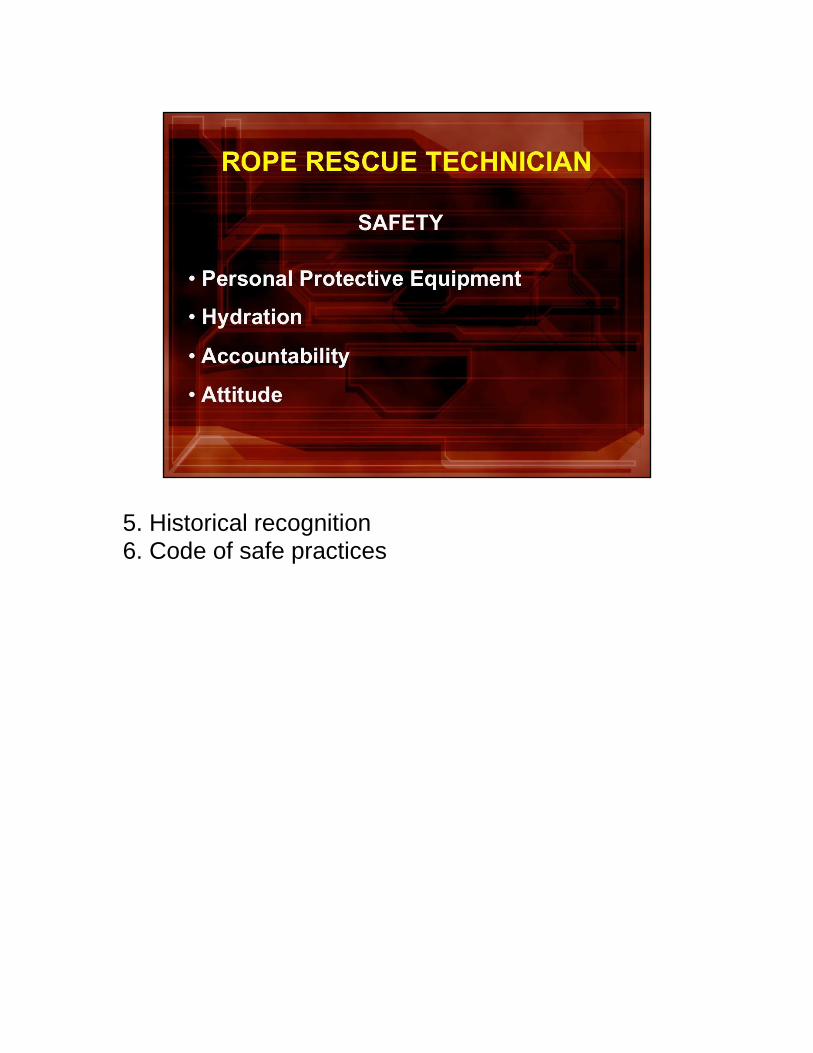
5. Historical recognition 6. Code of safe practices
2. All regulatory Requirements NFPA 1670, 1006, Rope Access
3. Will be adopted as the code of safe practices
Roll out number of classes based on the number of eligible applicants