
Rope Rescue - kristinandjerry.namekristinandjerry.name/cmru/rescue_info/Colorado Technical...
53
Rope Rescue COLORADO TECHNICAL RESCUE Colorado Technical Rescue 3301 South Field Street Lakewood, CO 80227 Phone 303.986.1992 • Fax 303.988.7041
-
Upload
phungtuyen -
Category
Documents
-
view
232 -
download
3
Transcript of Rope Rescue - kristinandjerry.namekristinandjerry.name/cmru/rescue_info/Colorado Technical...
Rope Rescue COLORADO TECHNICAL RESCUE
Colorado Technical Rescue
3301 South Field Street Lakewood, CO 80227
Phone 303.986.1992 • Fax 303.988.7041

Table of Contents
CHAPTER 1 ......................................................................................................................................................................... 4 INTRODUCTION TO ROPE RESCUE ............................................................................................................................ 4 RECREATIONAL AND COMMERCIAL ROPE USES................................................................................................. 4 ROPE RESCUE.................................................................................................................................................................... 6 NFPA 1983 ............................................................................................................................................................................ 6 NFPA 1006 ............................................................................................................................................................................ 6 NFPA 1670 ............................................................................................................................................................................ 7 INTERNATIONAL SYSTEM OF UNITS (SI) ................................................................................................................. 7 CHAPTER 2 ....................................................................................................................................................................... 10 ROPE................................................................................................................................................................................... 10 ROPE MATERIALS.......................................................................................................................................................... 10 ROPE CONSTRUCTION ................................................................................................................................................. 10 ROPE DESIGN AND TESTING ...................................................................................................................................... 11 STATIC VERSUS DYNAMIC ROPES ........................................................................................................................... 12 WEBBING .......................................................................................................................................................................... 13 ACCESSORY CORD......................................................................................................................................................... 13 CARE OF ROPES.............................................................................................................................................................. 14 CHAPTER 3 ....................................................................................................................................................................... 16 PERSONAL PROTECTIVE EQUIPMENT ................................................................................................................... 16 PERSONAL EQUIPMENT............................................................................................................................................... 16 HARNESSES ...................................................................................................................................................................... 17 CHAPTER 4 ....................................................................................................................................................................... 21 HARDWARE AND SOFTWARE .................................................................................................................................... 21 NFPA 1983 .......................................................................................................................................................................... 21 DESCENDERS................................................................................................................................................................... 22 ROPE GRABS .................................................................................................................................................................... 23 PULLEYS ........................................................................................................................................................................... 25 CHAPTER 5 ....................................................................................................................................................................... 26 KNOTS................................................................................................................................................................................ 26 DEFINITIONS ................................................................................................................................................................... 26 THE QUALITIES OF A RESCUE KNOT ...................................................................................................................... 26 AFFECTS OF KNOTS ON ROPE ................................................................................................................................... 27 TYPES OF KNOTS............................................................................................................................................................ 27

CHAPTER 6 ....................................................................................................................................................................... 28 ANCHORS.......................................................................................................................................................................... 28 TYPES OF ANCHORS...................................................................................................................................................... 28 EVALUATING ANCHORS.............................................................................................................................................. 31 COMPONENTS OF AN ANCHOR SYSTEM ................................................................................................................ 31 ANCHORING TECHNIQUES ......................................................................................................................................... 32 CHANGE OF DIRECTION ANCHORS (COD)............................................................................................................. 35 CHAPTER 7 ....................................................................................................................................................................... 38 BELAY SYSTEMS............................................................................................................................................................. 38 MINIMUM STANDARD OF A BELAY SYSTEM ........................................................................................................ 38 COMPONENTS OF A BELAY SYSTEM....................................................................................................................... 39 TANDEM PRUSIK AS A BELAY DEVICE ................................................................................................................... 39 RADIUM RELEASE HITCH ........................................................................................................................................... 41 CHAPTER 8 ....................................................................................................................................................................... 44 HAULING SYSTEMS ....................................................................................................................................................... 44 RESOURCES ..................................................................................................................................................................... 46 REFERENCES ................................................................................................................................................................... 47 ATTACHMENTS............................................................................................................................................................... 48 RAPPELLING COMMANDS AND SAFETY CHECK................................................................................................. 49 COMMAND & COMMUNICATION.............................................................................................................................. 50 RESCUE SYSTEMS TESTING ....................................................................................................................................... 51 MATERIAL STRENGTHS CARD .................................................................................................................................. 53
Chapter 1
Introduction to Rope Rescue
O B J E C T I V E S Identify the high angle environment
Discuss why NFPA 1983 was developed and its importance
Define the three tiered response system
Compare the Metric system of measurements to the English
Humans have always challenged themselves to conquer their environment. The
mountaineering environment has long been a quest where humans have been able to conquer due to advances in equipment and techniques. The main enemy to humans in this environment is gravity. Gravity is force of attraction between all masses in the universe, or the natural force that causes objects to move or tend to move towards the center of the Earth. There are several ways that humans operate in the high angle environment, depending primarily on their objective.
Three important considerations in rope rescue are gravity, the human factor, and friction
Recreational Rope Uses Mountaineering Mountaineering combines a number of skills, including climbing, camping, and snow and ice travel. People engaging in mountaineering often have a goal to endure weather and obstacles to reach the summit of a mountain under the harshest of conditions.
Climbing Also known as rock climbing, this is a specialized sport that may involve the ascent of smaller formations of rock, ice or a combination of terrain. Climbers may practice this sport by top roping, or running the rope through a carabineer at the top of the climb to the bottom. There a safety person, or belayer, controls the other end of the rope that is attached to the climber. In lead climbing the climber starts with the rope at the bottom, and then ascends, placing rock anchoring hardware, or protection, into the rock. Carabineers are then clipped into the protection, allowing the climber and the rope to move up. Free climbing is practiced by climbing without safety equipment such as rope
and protection. The climber is attached to rope that is anchored in a similar fashion as top roping. The rope is designed with a great deal of stretch to absorb the shock of a fall.
Vertical Caving Vertical caving is a sport that includes rope use as a means of descending and ascending a rope as a means to access the cave environment. This is a specialized sport that uses single rope technique (SRT). The rope is not intended as a means of protection, but as a descent and ascending device.
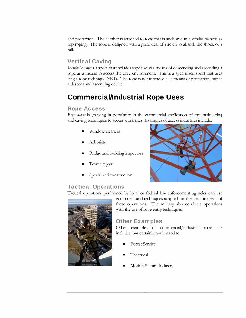
Commercial/Industrial Rope Uses Rope Access Rope access is growing in popularity in the commercial application of mountaineering and caving techniques to access work sites. Examples of access industries include:
• Window cleaners
• Arborists
• Bridge and building inspectors
• Tower repair
• Specialized construction
Tactical Operations Tactical operations performed by local or federal law enforcement agencies can use
equipment and techniques adapted for the specific needs of these operations. The military also conducts operations with the use of rope entry techniques.
Other Examples Other examples of commercial/industrial rope use includes, but certainly not limited to:
• Forest Service
• Theatrical
• Motion Picture Industry
5
Rope Rescue High Angle Rescue Rope rescue was originally practiced by fellow climbers or bystanders using the standard mountaineering equipment and techniques. Over time, these methods have
been replaced by specialized rescue teams, and equipment designed specifically for rescue purposes. Different terms have been used for this type of rescue, including vertical rescue, technical rescue and high angle rescue. High Angle is defined as a very steep environment in which a person is primarily supported by the rope system. One or more ropes are necessary to prevent the person from falling. This type of rescue should be considered a last resort, and used only when all other methods have been exhausted.
Fire Service Rescue Rope has long played an important part in the fire service for utility purposes. Firefighters have also used it for life safety purposes. On June 27th, 1980, a fire
on the seventh floor of an apartment complex in New York City quickly spread to an upper floor, trapping two firefighters. Crews attempted a rescue by using a ½” nylon rope. The two firefighters with a combined weight of 440 pounds were attached to the rope it suddenly failed, sending both firefighters to their death.
NFPA 1983 defined a one person load as 300 pounds. This was thought to be an average weight of a fire fighter with full gear, and allowed for some margin of error.
NFPA 1983 Standard on Fire Service Life Safety Rope and System Components The New York City incident spurred the development of NFPA 1983, Standard on Fire Service Life Safety Rope and System Components. Prior to this there was no recognized standard for rope rescue. NFPA 1983 helped to standardize many facets of the rope rescue discipline for the fire service community. Common terminology, equipment design, construction standards, and performance requirements are all components of the standard. The standard addressed the safety factor required for rope rescue systems. This will be discussed more in Chapter 2.
NFPA 1006 Standard for Rescue Technician Professional Qualifications The first edition of NFPA 1006 was approved on January 17th, 2003. It addresses general job performance requirements for a rescue technician as well as specific job
6
performance requirements for special rescue operations. Rescuers should some management and assessment skills for establishing and controlling a rope rescue scene.
The standard emphasizes a three tiered response of awareness, operations, and technician. At the awareness level, and at the completion of a recognized course, the student should be capable of recognizing conditions requiring rope rescue and making appropriate notifications to begin the rescue process.
An operations level rescuer should be capable of recognizing hazards, equipment use, and the techniques necessary to operate at a range of rope rescue incidents.
At the highest level, the technician should be capable in recognizing hazards, equipment use, and techniques necessary to operate and supervise at all rope rescue incidents.
NFPA 1670 Operations and Training for Technical Search and Rescue Incidents, 2004 Edition Similar to NFPA 1006, NFPA 1670 identifies the three tiered response concept. The authority having jurisdiction (AHJ) must ensure that all the rescuers that respond to a technical rescue incident shall be capable of identifying hazards and notify the next higher level of response when needed. The AHJ must evaluate its training program to determine whether the current training has prepared the organization to function at the established operational level under abnormal weather conditions, extremely hazardous operational conditions and other difficult situations.
Continual training and skills maintenance is paramount for a rescue team to stay proficient in the disciple. Applicable NFPA training standards should be adhered to ensure proficiency. Rope rescue can be physically demanding, rescuers must be physically and mentally prepared and be aware of “red flags”.
International System of Units (SI) In the discipline of rope rescue precise terms of measurement require the distinction between weight and mass. In the study of physics there are four fundamentals:
F U N D A M E N T A L E N G L I S H M E T R I C ( S I ) Time Second Second
Length Foot Meter
Mass Pound Kilogram
7

Force Slugs Newton
Mass is the measure of a body’s resistance to acceleration; the mass of a body is different from, but proportional to its weight.
Force is what is required to accelerate a mass. An accurate measurement of force is the Newton (N). A Newton is the unit of force required to accelerate a mass of 1 kilogram 1 meter
To better understand force, it is necessary to express it mathematically as:
Force = Mass x Acceleration (F=MA)
Conversion from SI
1kN = 225 LB
1N = 0.225 LB
Whereas mass is expressed in kilograms:
1 kilogram (kg) = 2.2 lbs
100 kg = 224 lbs, or average rescuer weight with gear
Acceleration is based on the gravity on Earth, or 10m/second² (SI)
F = MA
F = (100kg) (10m/s²)
F = (1000kg) (1m/s²)
Recall that 1N = (1kg) (1m/s²)
F = 1000N
F = 1kN
8

The equipment used in rope rescue that is tested is given values expressed in kilonewtons. All ratings and calculations in this manual will be based the SI measurements of force.
9
Chapter 2
Rope O B J E C T I V E S
Define the Kilonewton as a measurement of force
Identify the different materials used in rope
Identify the different rope construction types
Discuss the different elongation characteristics of rope
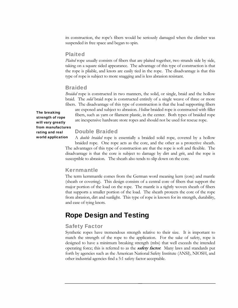
Rope Materials Rope has been used as a tool by early humans for survival. Naturally occurring ropes, such as vines, were the beginning of rope evolution. Early forms of man maid rope were natural fibers braided together to create a primitive rope. Unfortunately, natural rope is subject to deterioration and rotting. This forced humans to find an alternative to natural rope fibers.
Nylon was first produced by the DuPont Company in 1938. This revolutionary product proved to be useful in the military’s need for rope during WWII. Nylon proved to be a strong and reliable rope. In the years after the war, nylon was in short supply; however the increased demand for it spurred advancement in rope technology and construction. All though many materials have been introduced such as polyester, Kevlar, and polyethylene, today, nylon rope is believed to be the standard for rescue ropes.
Nylon ropes are approximately 10% stronger than polyester ropes when dry Nylon may lose 10% to 15% of its strength when wet They have good shock loading capabilities, with a 15-28% elongation at
breaking point
Nylon has a melting point of 480 degree F, and a high temperature working limit of 250 degree F
Nylon has good chemical resistant to alkalis
Rope Construction Laid The earliest form of construction of rope was laid construction. These ropes consist of bundles of fibers, called strands, which are twisted or laid around one another. Due to
10
its construction, the rope’s fibers would be seriously damaged when the climber was suspended in free space and began to spin.
Plaited Plaited rope usually consists of fibers that are plaited together, two strands side by side, taking on a square sided appearance. The advantage of this type of construction is that the rope is pliable, and knots are easily tied in the rope. The disadvantage is that this type of rope is subject to more snagging and is less abrasion resistant.
Braided Braided rope is constructed in two manners, the solid, or single, braid and the hollow braid. The solid braid rope is constructed entirely of a single weave of three or more fibers. The disadvantage of this type of construction is that the load supporting fibers
are exposed and subject to abrasion. Hollow braided rope is constructed with filler fibers, such as yarn or filament plastic, in the center. Both types of braided rope are inexpensive hardware store ropes and should not be used for rescue rope.
Double Braided A double braided rope is essentially a braided solid rope, covered by a hollow braided rope. One rope acts as the core, and the other as a protective sheath.
The advantages of this type of construction are that the rope is soft and flexible. The disadvantage is that the core is subject to damage by dirt and grit, and the rope is susceptible to abrasion. The sheath also tends to slip down on the core.
The breaking strength of rope will vary greatly from manufactures rating and real world application
Kernmantle The term kernmantle comes from the German word meaning kern (core) and mantle (sheath or covering). This design consists of a central core of fibers that support the major portion of the load on the rope. The mantle is a tightly woven sheath of fibers that supports a smaller portion of the load. The sheath protects the core of the rope from abrasion, dirt and sunlight. This type of rope is known for its strength, durability, and ease of tying knots.
Rope Design and Testing Safety Factor Synthetic ropes have tremendous strength relative to their size. It is important to match the strength of the rope to the application. For the sake of safety, rope is designed to have a minimum breaking strength (mbs) that well exceeds the intended operating force; this is referred to as the safety factor. Many laws and standards put forth by agencies such as the American National Safety Institute (ANSI), NIOSH, and other industrial agencies find a 5:1 safety factor acceptable.
11
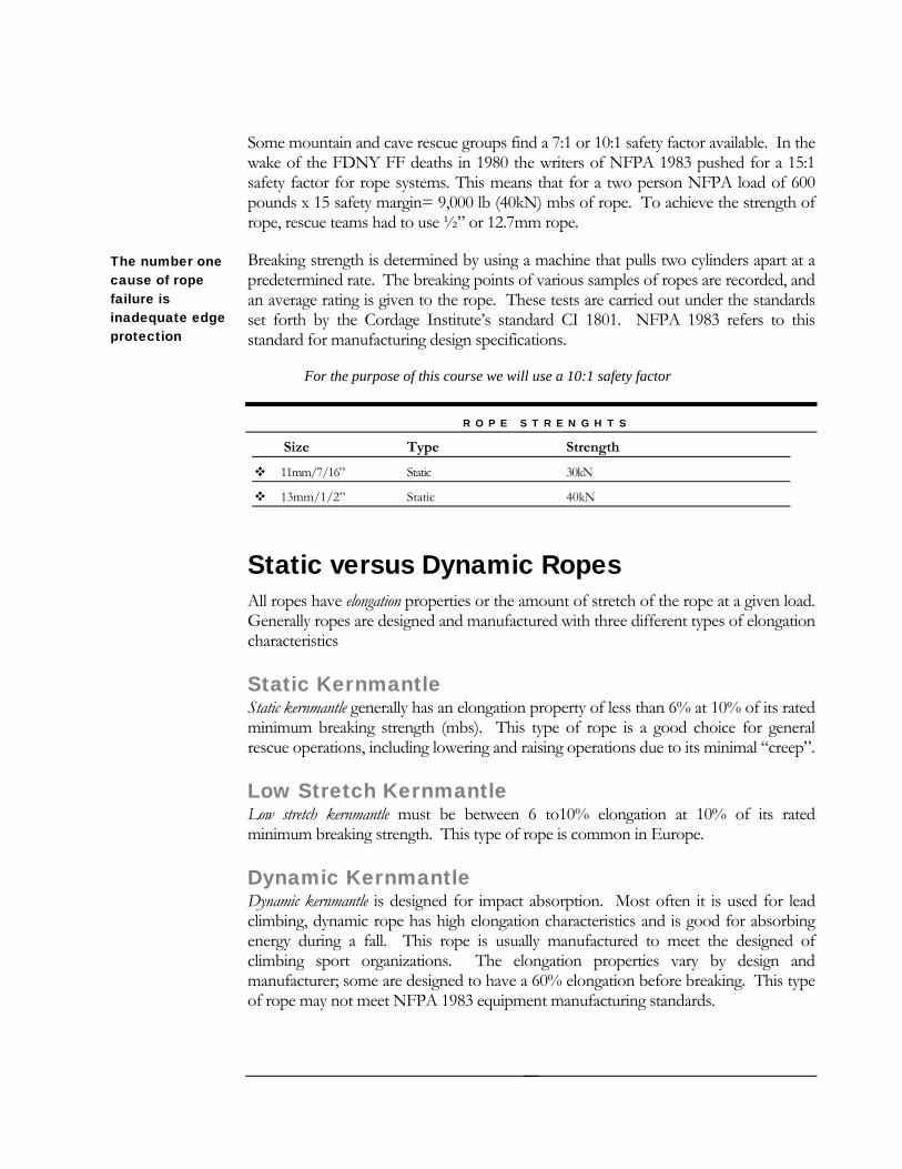
Some mountain and cave rescue groups find a 7:1 or 10:1 safety factor available. In the wake of the FDNY FF deaths in 1980 the writers of NFPA 1983 pushed for a 15:1 safety factor for rope systems. This means that for a two person NFPA load of 600 pounds x 15 safety margin= 9,000 lb (40kN) mbs of rope. To achieve the strength of rope, rescue teams had to use ½” or 12.7mm rope.
Breaking strength is determined by using a machine that pulls two cylinders apart at a predetermined rate. The breaking points of various samples of ropes are recorded, and an average rating is given to the rope. These tests are carried out under the standards set forth by the Cordage Institute’s standard CI 1801. NFPA 1983 refers to this standard for manufacturing design specifications.
The number one cause of rope failure is inadequate edge protection
For the purpose of this course we will use a 10:1 safety factor
R O P E S T R E N G H T S
Size Type Strength
11mm/7/16” Static 30kN
13mm/1/2” Static 40kN
Static versus Dynamic Ropes All ropes have elongation properties or the amount of stretch of the rope at a given load. Generally ropes are designed and manufactured with three different types of elongation characteristics
Static Kernmantle Static kernmantle generally has an elongation property of less than 6% at 10% of its rated minimum breaking strength (mbs). This type of rope is a good choice for general rescue operations, including lowering and raising operations due to its minimal “creep”.
Low Stretch Kernmantle Low stretch kernmantle must be between 6 to10% elongation at 10% of its rated minimum breaking strength. This type of rope is common in Europe.
Dynamic Kernmantle Dynamic kernmantle is designed for impact absorption. Most often it is used for lead climbing, dynamic rope has high elongation characteristics and is good for absorbing energy during a fall. This rope is usually manufactured to meet the designed of climbing sport organizations. The elongation properties vary by design and manufacturer; some are designed to have a 60% elongation before breaking. This type of rope may not meet NFPA 1983 equipment manufacturing standards.
12
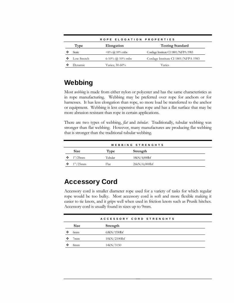
R O P E E L O G A T I O N P R O P E R T I E S
Type Elongation Testing Standard
Static <6% @ 10% mbs Cordage Institute CI 1801/NFPA 1983
Low Stretch 6-10% @ 10% mbs Cordage Institute CI 1801/NFPA 1983
Dynamic Varies; 30-60% Varies
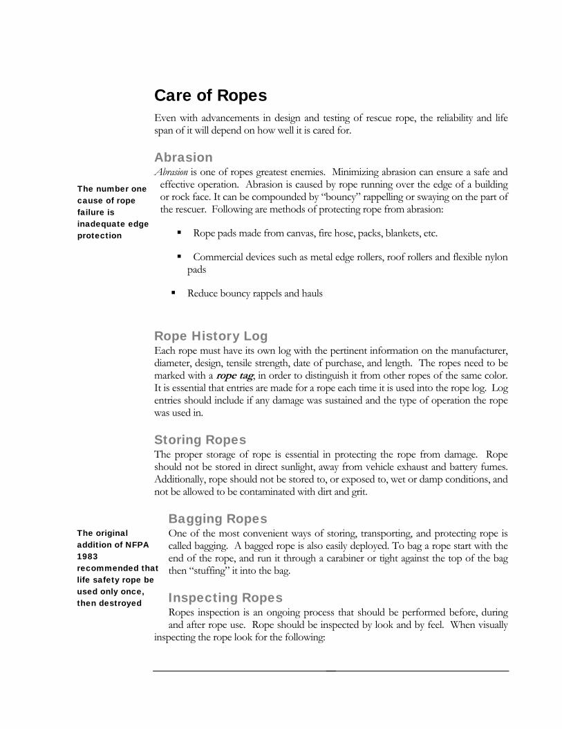
Webbing Most webbing is made from either nylon or polyester and has the same characteristics as in rope manufacturing. Webbing may be preferred over rope for anchors or for harnesses. It has less elongation than rope, so more load be transferred to the anchor or equipment. Webbing is less expensive than rope and has a flat surface that may be more abrasion resistant than rope in certain applications.
There are two types of webbing, flat and tubular. Traditionally, tubular webbing was stronger than flat webbing. However, many manufactures are producing flat webbing that is stronger than the traditional tubular webbing.
W E B B I N G S T R E N G H T S
Size Type Strength
1”/25mm Tubular 18kN/4,000lbf
1”/25mm Flat 26kN/6,000lbf
Accessory Cord Accessory cord is smaller diameter rope used for a variety of tasks for which regular rope would be too bulky. Most accessory cord is soft and more flexible making it easier to tie knots, and it grips well when used in friction knots such as Prusik hitches. Accessory cord is usually found in sizes up to 9mm.
A C C E S S O R Y C O R D S T R E N G H T S
Size Strength
6mm 6.8kN/1550lbf
7mm 10kN/2100lbf
8mm 14kN/3150
13
Care of Ropes Even with advancements in design and testing of rescue rope, the reliability and life span of it will depend on how well it is cared for.
Abrasion Abrasion is one of ropes greatest enemies. Minimizing abrasion can ensure a safe and
effective operation. Abrasion is caused by rope running over the edge of a building or rock face. It can be compounded by “bouncy” rappelling or swaying on the part of the rescuer. Following are methods of protecting rope from abrasion:
The number one cause of rope failure is inadequate edge protection Rope pads made from canvas, fire hose, packs, blankets, etc.
Commercial devices such as metal edge rollers, roof rollers and flexible nylon pads
Reduce bouncy rappels and hauls
Rope History Log Each rope must have its own log with the pertinent information on the manufacturer, diameter, design, tensile strength, date of purchase, and length. The ropes need to be marked with a rope tag, in order to distinguish it from other ropes of the same color. It is essential that entries are made for a rope each time it is used into the rope log. Log entries should include if any damage was sustained and the type of operation the rope was used in.
Storing Ropes The proper storage of rope is essential in protecting the rope from damage. Rope should not be stored in direct sunlight, away from vehicle exhaust and battery fumes. Additionally, rope should not be stored to, or exposed to, wet or damp conditions, and not be allowed to be contaminated with dirt and grit.
Bagging Ropes One of the most convenient ways of storing, transporting, and protecting rope is called bagging. A bagged rope is also easily deployed. To bag a rope start with the end of the rope, and run it through a carabiner or tight against the top of the bag then “stuffing” it into the bag.
Inspecting Ropes Ropes inspection is an ongoing process that should be performed before, during and after rope use. Rope should be inspected by look and by feel. When visually
inspecting the rope look for the following:
The original addition of NFPA 1983 recommended that life safety rope be used only once, then destroyed
14
Discoloration: This could indicate chemical or sunlight damage
Glossy marks: May be a result of heat damage
Exposed core fibers: These should be white in color on most ropes
Variance in size and diameter or soft spots: This may indicate core damage
Contamination with dirt, grit or chemicals
Cleaning Ropes Eventually, ropes will need to be cleaned. The most important rule to follow is to follow manufactures recommendations for cleaning. Ropes can become damaged by dirt and debris being forced into the core of the rope. Ropes can also be damaged by stepping on them. A general rule of thumb is to never step on rope, it can force even more debris into the core. Metal particles may also be forced into the rope as it runs through hardware, such as rappel devices.
There are commercially made rope washing devices that use jets of water to wash the rope as it is ran through a tube. Another option is to wash the rope in a washing machine. The following are recommendations for washing rope in a washing machine:
Coil the rope in an accepted coil, such as the chain coil, place in a mesh bag to prevent tangling on the agitator
Use gentle soaps that are safe for synthetics, these are most likely safe for cleaning rope; do not use bleach
Use cold water setting
Air dry only out of direct sunlight; do not use a clothes dryer
Webbing can be cleaned for in the same manner
15
Chapter 3
Personal Protective Equipment
O B J E C T I V E S Identify the different classes of harnesses per NFPA 1983
Identify proper helmet use for rope rescue
Review other personal protective equipment used in rope rescue
Personal Equipment Helmet The helmet is a vital piece of equipment that the rescuer uses. It can protect the wearer from injury or reduce the severity of injury from falling debris such as rocks or climbing hardware.
The helmet should be designed to be used in a rope rescue setting by being impact resistant and to adsorb impact. Construction type helmets, motorcycle and bicycle helmets are not suitable for the rope rescue environment. The helmet should be equipped with a three point harness; single or elastic harnesses may not be secure enough and fall off of the rescuer while in use and should be avoided.
NFPA 1951, Standard on Protective Ensemble for USAR Operations specifies types of helmets used in urban search and rescue and may be a good resource for selecting a proper helmet.
Gloves Gloves are used in rope rescue to protect the hands against burns and abrasions from running ropes. Gloves should be light enough to enable the rescuer to maintain a sense of feel of the rope. Soft leather gloves can be used in rope rescue, however commercial versions are available.
Gloves that have been contaminated with oil, products of fire and that are dirty should not be used for rope rescue work
Harnesses NFPA 1983, Standard on Fire Service Life Safety Rope and System Components This standard classifies harnesses into three classes:
Class I A light duty harness meant for light duty work and emergency egress by one person with a design load of 1.33 kN.
Ladder belts are designed only to prevent falls from a ladder and are not intended for the rope rescue environment
Class II A seat harness that secures around waist and around thighs or under buttocks and designed for one person, or when another person’s weight may be transferred to the harness during the course of a rescue. The harness is designed for a 2.67 kN, two person load.
Class III A full body harness designed for rescue loads, fall protection and for rescues in which inversion may occur. A class III harness fastens around the waist, around thighs or under buttocks, and over the shoulders with a design load of 2.67 kN.
Improvised Harnesses Improvised harnesses can be made from webbing and used when a commercial harness is not available.
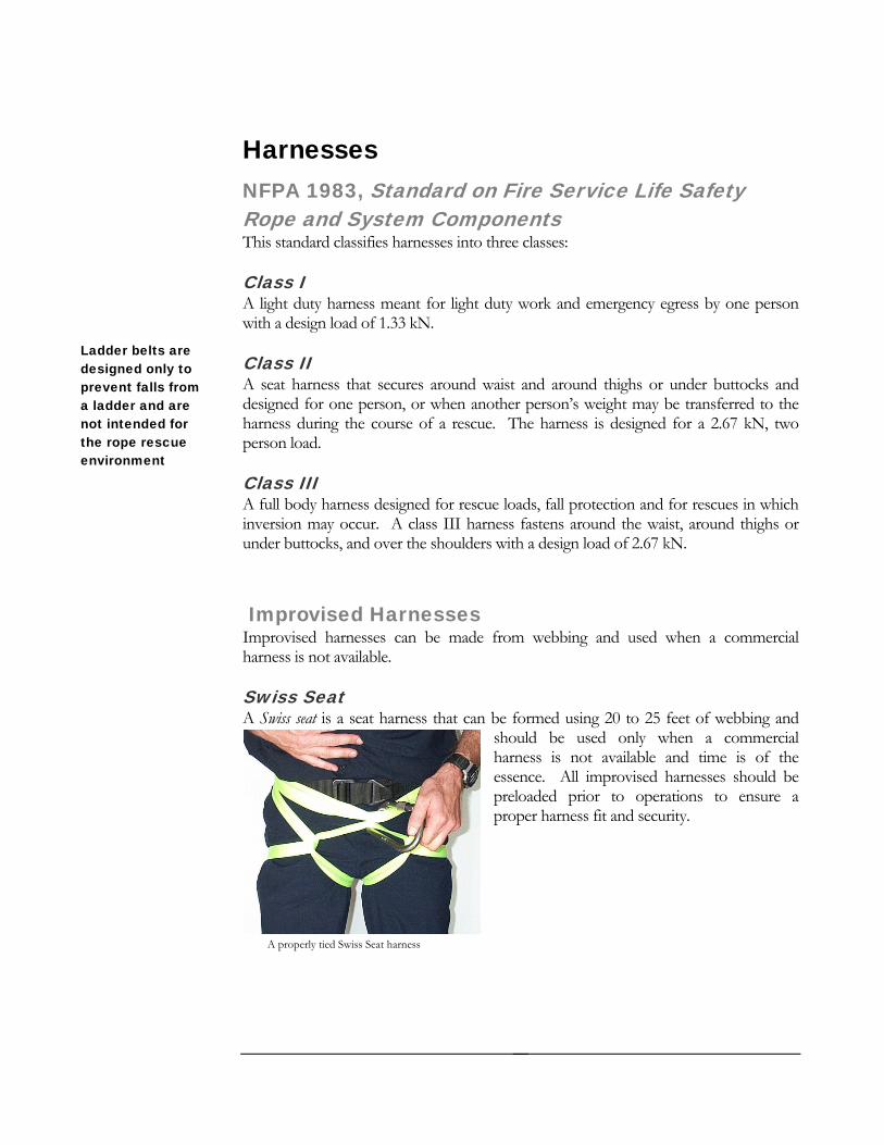
Swiss Seat A Swiss seat is a seat harness that can be formed using 20 to 25 feet of webbing and
should be used only when a commercial harness is not available and time is of the essence. All improvised harnesses should be preloaded prior to operations to ensure a proper harness fit and security.
A properly tied Swiss Seat harness
17
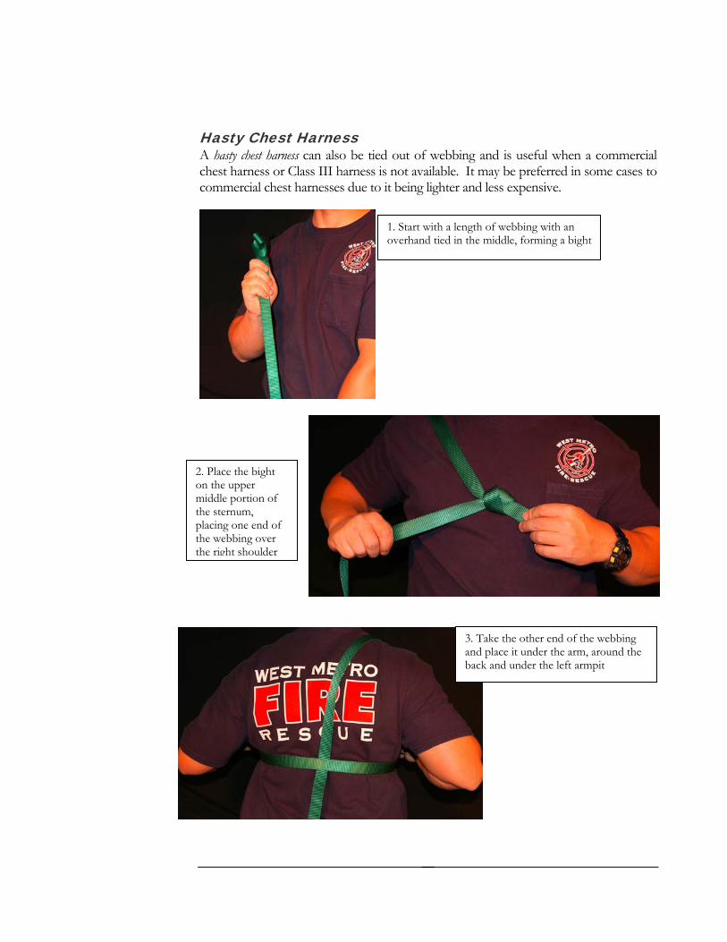
Hasty Chest Harness A hasty chest harness can also be tied out of webbing and is useful when a commercial chest harness or Class III harness is not available. It may be preferred in some cases to commercial chest harnesses due to it being lighter and less expensive.
1. Start with a length of webbing with an overhand tied in the middle, forming a bight
2. Place the bight on the upper middle portion of the sternum, placing one end of the webbing over the right shoulder
3. Take the other end of the webbing and place it under the arm, around the back and under the left armpit
18
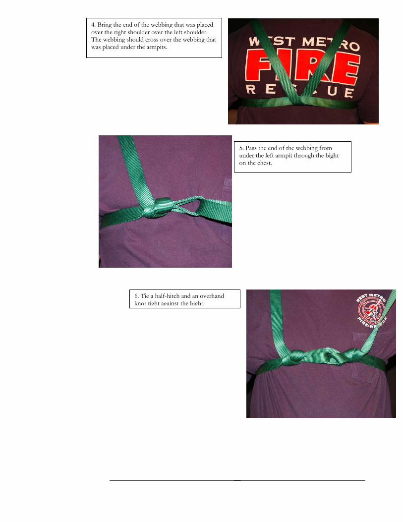
4. Bring the end of the webbing that was placed over the right shoulder over the left shoulder. The webbing should cross over the webbing that was placed under the armpits.
5. Pass the end of the webbing from under the left armpit through the bight on the chest.
6. Tie a half-hitch and an overhand knot tight against the bight.
19
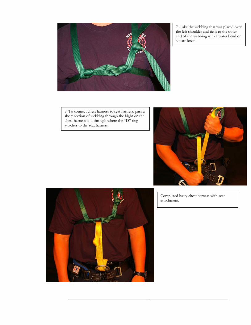
7. Take the webbing that was placed over the left shoulder and tie it to the other end of the webbing with a water bend or square knot.
8. To connect chest harness to seat harness, pass a short section of webbing through the bight on the chest harness and through where the “D” ring attaches to the seat harness.
Completed hasty chest harness with seat attachment.
20
Chapter 4
Hardware and Software O B J E C T I V E S
Identify the different types of hardware used in rope rescue
Identify the care and inspection procedures for hardware
Recognize the need for rope abrasion protection
Rope rescue gear can be classified as either software or hardware. Software is made from some kind of fiber, and hardware is made from some type of metal. There has been much advancement in the types of metals and alloys that are used in the construction of rope rescue hardware.
NFPA 1983 According to NFPA 1983, hardware is a type of auxiliary equipment that includes, but not limited to, ascent devices, carabiners, descent control devices, pulleys, rings and snap links. Most hardware will be marked if it meats the NFPA 1983 standard.
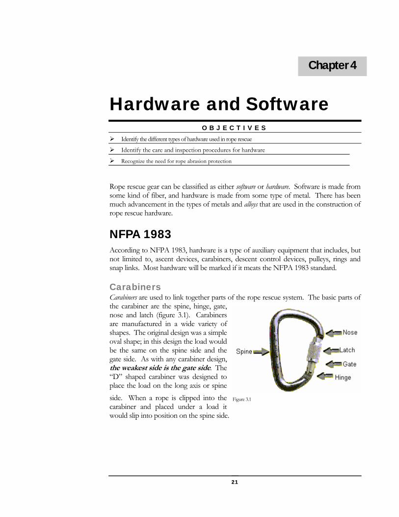
Carabiners Carabiners are used to link together parts of the rope rescue system. The basic parts of the carabiner are the spine, hinge, gate, nose and latch (figure 3.1). Carabiners are manufactured in a wide variety of shapes. The original design was a simple oval shape; in this design the load would be the same on the spine side and the gate side. As with any carabiner design, the weakest side is the gate side. The “D” shaped carabiner was designed to place the load on the long axis or spine side. When a rope is clipped into the carabiner and placed under a load it would slip into position on the spine side.
Figure 3.1
21 21
22
-locking carabiner has the potential for the gate to be opened by contact with the wall or the edge or another piece of equipm are preferred in all life safety
, two non-locking carabiners can be
rn amongst most rescuers. Carabiners can e made of either steel, aluminum or an alloy. Aluminum carabiners usually are lighter,
but may not be as strong as steel. Steel carabiners are heavier but stronger than
abeling AA system: Stamped with major axis, minor axis, and gate rengths in kN.
or one G is designed for general rescue use with a minimum major
strength of 40kN.
friction devices. The user places the rope in ss to descend the rope at a controlled speed. escenders available. All work by applying e rescuer.
pe rescue. It is designed for the rope to ontour around the large ring. The ears prevent
the rope from slipping over the ring to form a
Three way loadis the potentially dangerous loadof a carabiner inthree axis’s
Carabiners also come in locking and non-locking configurations. The non
ent. Locking carabinersapplications. If locking carabiners are not availableused with the gates opposing.
The weight of the equipment is a big conceb
aluminum. Steel carabiners are susceptible to rusting, if using steel, make sure they are plated, and there are stainless steel hinge springs.
Carabiner Ling
CEN/UIopened st
ing
NFPA system: Carabiners meeting NFPA 1983 standard are marked with “meets NFPA 1983, 2001 ED”. Will also have either an L or G
stamped into the frame. The L indicates light use and is designed fperson loads. The axis breaking
Descenders Descenders are essentially descent control orthe rappel device, attaches it to their harneThere are many types and designs of dfriction to the rope to slow the travel of th
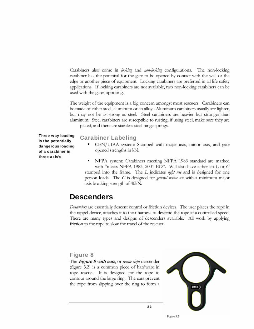
Figure 8 The Figure 8 with ears, or rescue eight descender (figure 3.2) is a common piece of hardware in roc
Figure 3.2
gi
23
rth hitch. The larger size helps to dissipate heat better, and accommodates larger diameter rope.
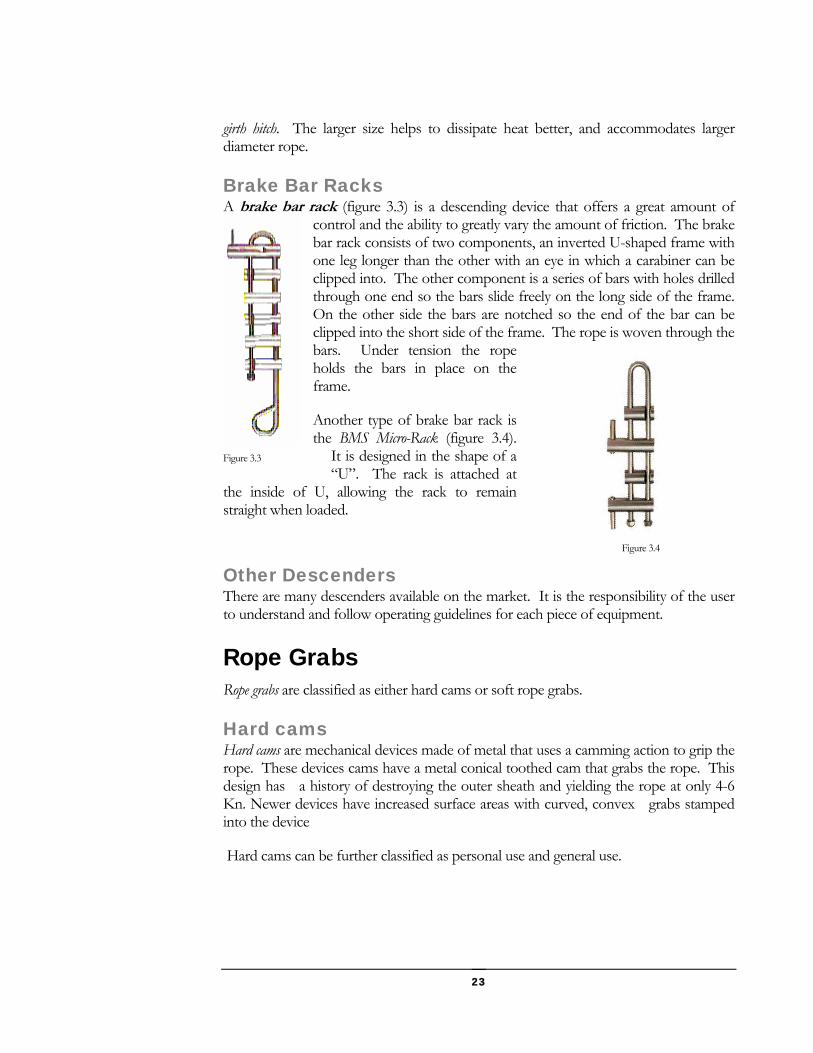
rake Bar Racks A brake bar rack (figure 3.3) is a descending device that offers a great amount of
d so the bars slide freely on the long side of the frame. On the other side the bars are notched so the end of the bar can be
Another type of brake bar rack is (figure 3.4).
e inside of to remain straight w n
OtheThere are many descenders available on the market. It is the responsibility of the user
operating guidelines for each piece of equipment.
ard cams are mechanical devices made of metal that uses a camming action to grip the rope. These devices cams have a metal conical toothed cam that grabs the rope. This
sign has a history of destroying the outer sheath and yielding the rope at only 4-6 vices have increased surface areas with curved, convex grabs stamped
e and general use.
B
control and the ability to greatly vary the amount of friction. The brake bar rack consists of two components, an inverted U-shaped frame with one leg longer than the other with an eye in which a carabiner can be clipped into. The other component is a series of bars with holes drilled through one en
clipped into the short side of the frame. The rope is woven through the bars. Under tension the rope holds the bars in place on the frame.
the BMS Micro-Rack It is designed in the shape of a “U”. The rack is attached at
U, allowing the rack
Figure 3.3
thhe loaded.
r Descenders Figure 3.4
to understand and follow
Rope Grabs Rope grabs are classified as either hard cams or soft rope grabs.
Hard cams H
deKn. Newer deinto the device
Hard cams can be further classified as personal us
Personal Use Ascenders These devices are designed for a single person load for ascending rope and are not
intended to be used with hauling systems where forces may be too great (figure 3.6). Personal use ascenders are generally used in pairs, with left and right handed models.
General Use Ascenders
General use ascenders are designedevices for heavier loads. These devices may perform better on
d to be used as progress capture
rope that may be wet, muddy, or icy. These devices may also be used as ascenders, but generally do no use ascenders.
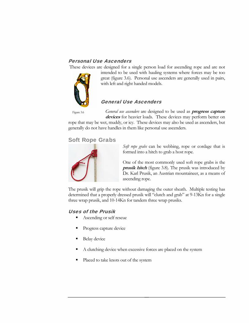
Rope G webbing, rope or cordage that is grab a host rope.
One of the most commonly used soft rope grabs is the prusik hitch (figure 3.8). The prusik was introduced by
rl Prusik, an Austrian mountaineer, as a means of
testing has determined that a properly dressed prusik will “clutch and grab” at 9-13Kn for a single
-14Kn for tandem three wrap prusiks.
Ascending or self rescue
Figure 3.6
t have handles in them like personal
rabs Soft rope grabs can beformed into a hitch to
Soft
Dr. Kaascending rope.
The prusik will grip the rope without damaging the outer sheath. Multiple
three wrap prusik, and 10
Uses of the Prusik
Progress capture device
Belay device
A clutching device when excessive forces are placed on the system
Placed to take knots out of the system
24
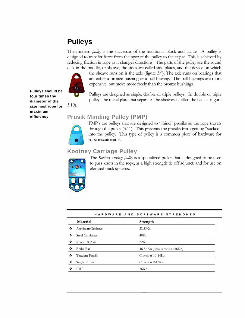
Pulleys The modern pulley is the successor of the traditional block and tackle. A pulley is d of the pulley to the output. This is achieved by
the share eiexpen ronze bushings.
Pulleys are designed as single, double or triple pulleys. In double or triple pulleys sheaves is called the becket (figure
3.10).
m getting “sucked” This type of pulley is a common piece of hardware for s.
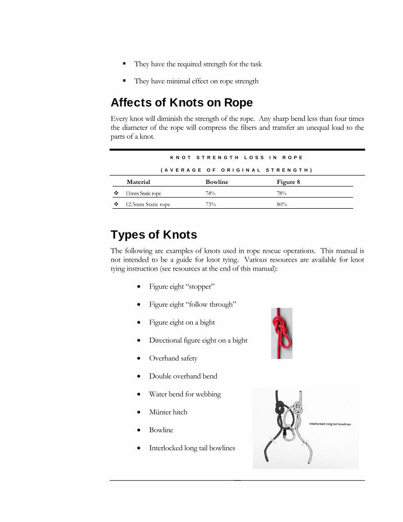
Kootney Carriage PThe Kootney carriato pass knots in televated track sys
N D S O F T W A R E S T R E N G H T S
esigned to transfer force from the inputreducing friction in rope as it changes directions. The parts of the pulley are the round disk in the middle, or sheave, the sides are called side plates, and the device on which
eave runs on is the axle (figure 3.9). The axle runs on bearings that ther a bronze bushing or a ball bearing. The ball bearings are more sive, but move more freely than the b
Pulleys should be four times the diameter of the size host rope for maximum efficiency
the metal plate that separates the
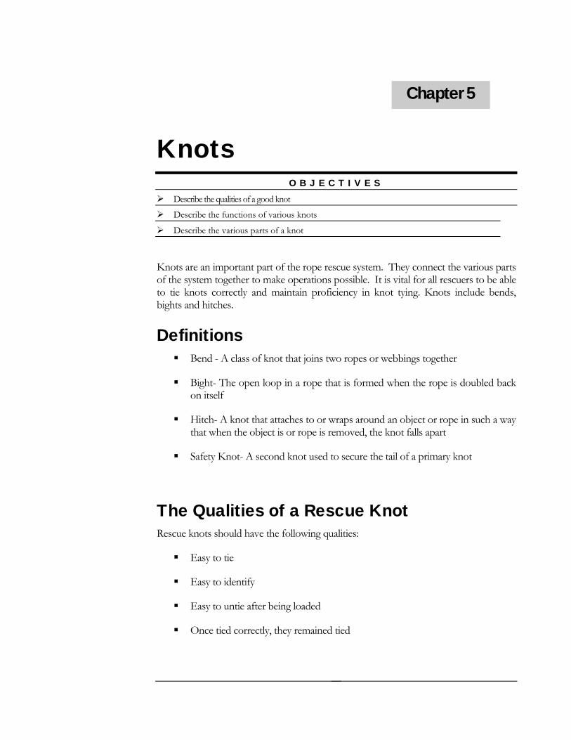
Prusik Minding Pulley (PMP) PMP’s are pulleys that are designed to “mind” prusiks as the rope travels through the pulley (3.11). This prevents the prusiks frointo the pulley. rope rescue team
ulley ge pulley is a specialized pulley that is designed to be used he rope, as a high strength tie off adjunct, and for use on tems.
H A R D W A R E A
Strength
Material
Aluminum Carabiner 22-30Kn
e 40Kn St el Carabiner
Rescue 8 Plate 22Kn
Brake Bar 46-56Kn (breaks rope at 26Kn)
n t 10-14Kn Ta dem Prusik Clutch a
Single Prusik Clutch at 9-13Kn
PMP 36Kn
25
Chapter 5
Knots O B J E C T I V E S
Describe the qualities of a good knot
Describe
Describe
the functions of various knots
the various parts of a knot
Knots are an important part of the rope rescueof the system
system. They connect the various parts
to tie knotsbights and h
Definitions
Bighon it
Hitch- A knot that attaches to or wraps around an object or rope in such a way that when the object is or rope is removed, the knot falls apart
Safety Knot- A second knot used to secure the tail of a primary knot
T a ReR
e
o entify
together to make operations possible. It is vital for all rescuers to be able correctly and maintain proficiency in knot tying. Knots include bends, itches.
Bend - A class of knot that joins two ropes or webbings together
t- The open loop in a rope that is formed when the rope is doubled back self
he Qualities of scue Knot escue knots should have the following qualities:
Easy to ti
Easy t id
Easy to untie after being loaded
Once tied correctly, they remained tied
26
They have the required strength for the task
They have minimal effect on rope strength
nots on Rope e strength of the rope. Any sharp bend less than four times
the diameter of the rope will c ansfer an unequal load to the t
L O S S I N R O P E
Affects of KEvery knot will diminish th
ompress the fibers and trpar s of a knot.
K N O T S T R E N G T H
( A V E R A G E O F O R I G I N A L S T R E N G T H )
Material Bowline Figure 8
11mm Static rope 74% 78%
12.5mm Static rope 73% 80%
Types of Knots The l his manual is not intended to be a guide for knot tying. Various resources are available for knot tyin
• Figure eight “stopper”
• Directional figure eight on a bight
bend for webbing
h
fo lowing are examples of knots used in rope rescue operations. T
g instruction (see resources at the end of this manual):
• Figure eight “follow through”
• Figure eight on a bight
• Overhand safety
• Double overhand bend
• Water
• Münter hitc
• Bowline
• Interlocked long tail bowlines
27

AnchE S
ors O B J E C T I V
Describe various types of anchors
Describe how to evaluate anchors
Define the parts of a anchor system
Describe anchoring techniques
As the name implies the anchor is the foundation of the rope rescue system. Anchor selection and anc
Tnchors on Structures
Man made anchors are generally found on structures, but can include the following:
beams
Large masonry walls and structures
Anchors for window washers
S p
E v
NaturNatural a o and trees, and may include shrubs and bushes. Trees should be evaluated for rot, if it’s alive or dead, and a substantial root system. Boulders should have no movement under foot and firmly embedded into the ground. Shrubs and bushes may be an alternative if no other anchor is available, and if it is used as part of an anc r
Impro s ors Improvised anchors can be used when no other suitable anchor is available. These types of anchors lu
horing techniques are crucial to a safe operation.
ypes of Anchors A
Structural columns and
Stairwell supports
cu pers
le ator housings
al Anchors nch rs include boulders
ho system.
vi ed Anch
Chapter 6
An anchor that is of significant strength and can withstand high forces is considered to be “bombproof”.
inc de:
28
Emergency apparatus - An axle or tire may be used on a vehicle for an anchor. tag out procedures should be followed to prevent the vehicle from
s an anchor
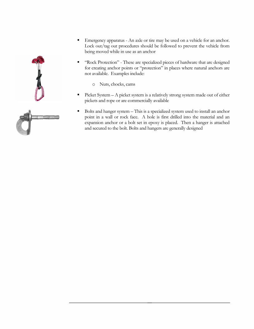
“Rock Protection” - Th of hardware that are designed ints or “protection” in places where natural anchors are
clude:
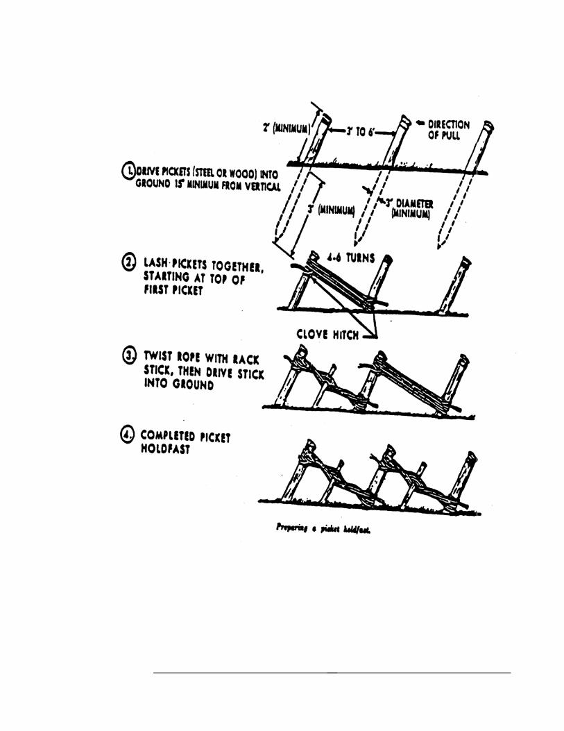
Picket System – A picket system is a relatively strong system made out of either
to install an anchor
set in epoxy is placed. Then a hanger is attached hangers are generally designed
Lock out/being moved while in use a
ese are specialized pieces for creating anchor ponot available. Examples in
o Nuts, chocks, cams
pickets and rope or are commercially available
Bolts and hanger system – This is a specialized system usedpoint in a wall or rock face. A hole is first drilled into the material and an expansion anchor or a bolt and secured to the bolt. Bolts and
29
30

Evaluating Anchors These factors should considered when evaluating anchors
The condition of the anchor: A live tree is generally preferred over a dead tree. Deteriorated components on a structure should be avoided
The strength of the anchor: Anchors of larger mass or structural in nature can generally withstand greater forces
The location of force on the anchor point: A anchor point higher on a anchor, such as a tree, puts more stress on the anchor than a lower attachment point
Components of an Anchor System An anchor system is made up of the following items:
1. Anchor point(s): A single or multiple anchor points may be used
2. Anchor focal point:: This is where the rope rescue system, such as the belay line and main line, is attached to the anchor system
Anchor system
31
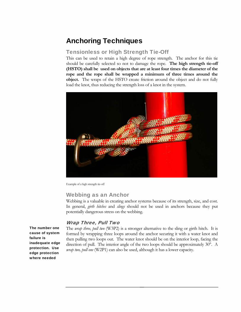
Anchoring Techniques ngth Tie-Off ree of rope strength. The anchor for this tie
The high strength tie-off eter of the
ropobject. t and do not fully load the knot, thus reducing the stre .
Tensionless or High StreThis can be used to retain a high degshould be carefully selected so not to damage the rope. (HSTO) shall be used on objects that are at least four times the diam
e and the rope shall be wrapped a minimum of three times around the The wraps of the HSTO create friction around the objec
ngth loss of a knot in the system
Example of a high strength tie-off
Webbing as an Anchor Webbing is a valuable in creating anchor systems because of its strength, size, and cost. In general, girth hitches and slings should not be used in anchors because they put potentially dangerous stress on the webbing.
Wrap Three, Pull Two The wrap three, pull two (W3P2) is a stronger alternative to the sling or girth hitch. It is formed by wrapping three loops around the anchor securing it with a water knot and then pulling two loops out. The water knot should be on the interior loop, facing the direction of pull. The interior angle of the two loops should be approximately 30°. A wrap two, pull one (W2P1) can also be used, although it has a lower capacity.
The number one cause of system failure is inadequate edge protection. Use edge protection where needed
32
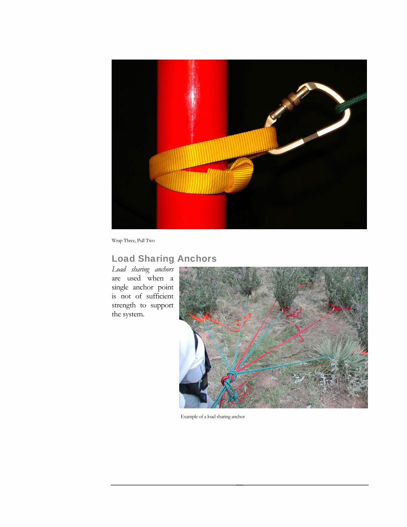
Wrap Three, Pull Two
Load Sharing Anchors Load sharing anchors are used when a single anchor point is not of sufficient strength to support
the system.
Example of a load sharing anchor
33
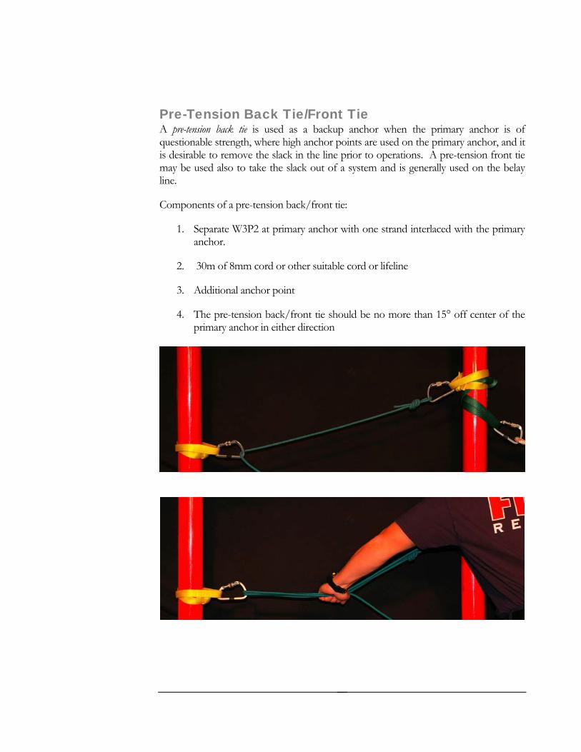
Pre-Tension Back Tie/Front Tie A pre-tension back tie is used as a backup anchor when the primary anchor is of questionable strength, where high anchor points are used on the primary anchor, and it is desirable to remove the slack in the line prior to operations. A pre-tension front tie may be used also to take the slack out of a system and is generally used on the belay line.
Components of a pre-tension back/front tie:
1. Separate W3P2 at primary anchor with one strand interlaced with the primary anchor.
2. 30m of 8mm cord or other suitable cord or lifeline
3. Additional anchor point
4. The pre-tension back/front tie should be no more than 15° off center of the primary anchor in either direction
34

Pre-tension back tie
Change of Direction Anchors (COD)
Definition: A rigging technique for redirecting location or angle for a safer and more efficient
rope rescue systems to a more desirable operation.
CO Main anchor system not inline with direction of load to be raised or lowered.
COD may be used to avoid abrasive edge protection problem by elevating the
COD may be used to elevate a high anchor point above an edge to help deploy the litter over the edge during a lowering or hauling operation.
Rigging Change of Direction The principles and considerations of simple anchor points shall be used.
The critical angle and force vectors do compromise COD anchors.
For COD anchors the critical angle and force vectors are OPPOSITE from multiple nchor point systems. The narrower the angle of the COD anchor the MORE
D anchor use
rigging above the edge.
aforce is put on the anchor. When the rope legs extending from a COD attachment become parallel (turned 180 degrees), twice the load is developed on the COD anchor. In effect, a 2:1 mechanical advantage (or disadvantage) has occurred.
In summary, use COD system components when necessary, just keep the angle as wide as possible from the main anchor system.
35
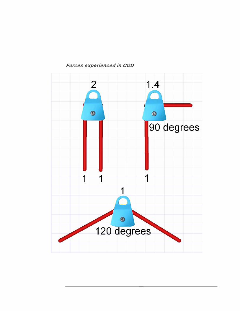
es experienced in COD
Forc
36

S T R E N G T H O F A N C H O R C O M P O N E N T S
Component Drop Test Breaking Strength
25mm Tubular Webbing 18kN
25mm Flat Webbing 26kN
W2P1 Tubular 24-26 kN
W2P1 Flat 32kN
W3P2 Tubular 35-40kN
W3P2 Flat 46kN
37

Belay Systems O B J E C T I V E S
Define a belay
Describe th
system
e advantages of lower versus rappelling systems
To belay is to protect a rescuer or a load from falling if failure of the mainline or an uncontrolled descent occurs. A belay system allows for redundancy, thus increasing the safety factor in rope rescue. This can be done by using a two-rope system, one for the mainline and one for the belay line. The belay line shall never be loaded during normal operation, only during a failure of the mainline or an uncontrolled descent.
When a belay system is activated due to an uncontrolled descent or a mainline failure, greater forces are experienced throughout the belay system due to “shock loading”. Suitable anchors must be selected in order to account for these forces. Because the belay line is not under tension during normal operations, there may be stretch in the belay system before it stops the load due to the elongation properties of the rope. To minimize these, it is recommended that pre tension front ties be used in a belay system to take as much stretch out of the line as possible.
Minimum Standard of a Belay System From 1982-1989 the British Columbia Council of Technical Rescue (BCCTR) critically analyzed and drop tested numerous types of belay devices and established a minimum standard for belay system performance:
With a 200kG (or 2kN) load, attached to 3m of rope in-service the belay system must be able to:
Withstand a 1m drop of the load
Stop it in less than 1m additional travel
The system not experience forces greater than 15kN
Host rope must maintain at least 80% of its original strength
Chapter 7
The “worst case scenario” in rope rescue is to have a fall of 1m with 3m of rope in service
38
Components of a Belay System The following components make up the belay system:
e same strength as the main line
a braking device that the belay line is ran through to stop the rescuer in case o r mainline failure. There are many belay devices available commercially and site
previously outlined.
Belayer- The belayer plays a vital role in the overall operation of the rope system. They are responsible for controlling the belay device with the proper technique and keeping slack
le, but they may not allow for a great deal of extension. A Radium Release Hitch (RRH) is a site built release device that is inexpensive and allows for
Many tests have proven the effectiveness of the tandem prusik as a belay device. It is very inexpensive to construct, lightweight, and with proper training, easy to setup and operate. The tandem pru e that will clutch and re-grab the rope at 9-13kN. h -sheath the host rope and will work on rope that is st , se of two prusik provides only 1-3kN of d rs twice the amount of nylon to be melt b
andem prusik belays should consist of the following: Triple wrap on the host rope
A single prusik is suitable for ratchets and connecting a pulley system to a mainline
Belay line- Shall be rated at a minimum th
Belay device- A belay device is essentially f uncontrolled descent o
built. Any belay device used must meet the requirements as
out of the belay line
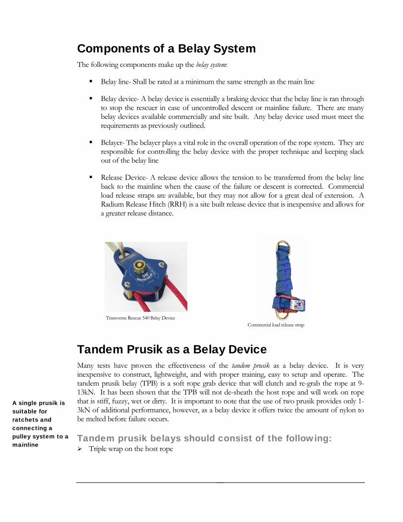
Release Device- A release device allows the tension to be transferred from the belay line back to the mainline when the cause of the failure or descent is corrected. Commercial load release straps are availab
a greater release distance.
Commercial load release strap Transverse Rescue 540 Belay Device
Tandem Prusik as a Belay Device
sik belay (TPB) is a soft rope grab devicIt as been shown that the TPB will not deiff fuzzy, wet or dirty. It is important to note that the uad itional performance, however, as a belay device it offeed efore failure occurs.
T
39
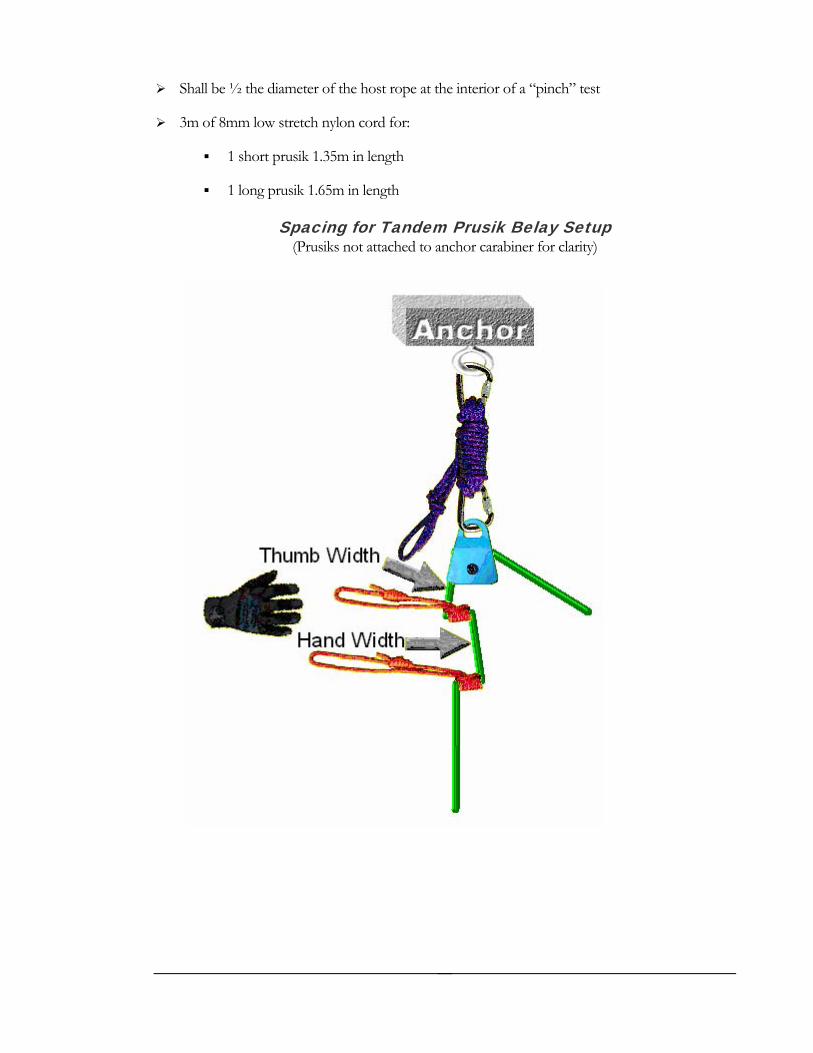
Shall be ½ the diameter of the host rope at the interior of a “pinch” test
3m of 8mm low stretch nylon cord for:
1 short prusik 1.35m in length
1 long prusik 1.65m in length
Spacing for Tandem Prusik Belay Setup (Prusiks not attached to anchor carabiner for clarity)
40
R dium Release Hitch aThe Radium Release Hitch (RRH) was developed after comparative analysis and testing of available release devices from 1997 to 1999.
Materials r 10m of 8mm nylo
2 locking carabiners
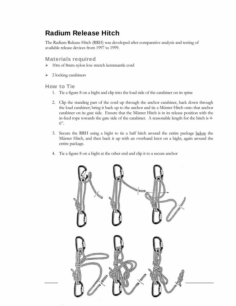
How to Tie 1. Tie a figure 8 on a bight and clip into the load side of the carabiner on its spine
2. Clip the standing part of the cord up through the anchor carabiner, back down through the load carabiner; bring it back up to the anchor and tie a Münter Hitch onto that anchor carabiner on its gate side. Ensure that the Münter Hitch is in its release position with the in-feed rope towards the gate side of the carabiner. A reasonable length for the hitch is 4-6”.
3. Secure the RRH using a bight to tie a half hitch around the entire package below
equired n low stretch kernmantle cord
the Münter Hitch, and then back it up with an overhand knot on a bight, again around the entire package.
4. Tie a figure 8 on a bight at the other end and clip it to a secure anchor
41
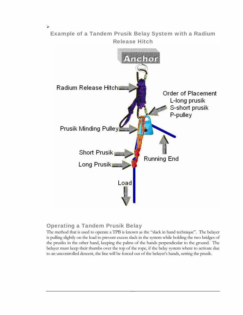
ik Belay System with a Radium Example of a Tandem PrusRelease Hitch
Operating a Tandem Prusik Belay The method that is used to operate a TPB is known as the “slack in hand technique”. The belayer is pulling slightly on the load to prevent excess slack in the system while holding the two bridges of the prusiks in the other hand, keeping the palms of the hands perpendicular to the ground. The belayer must keep their thumbs over the top of the rope, if the belay system where to activate due to an uncontrolled descent, the line will be forced out of the belayer’s hands, setting the prusik.
42
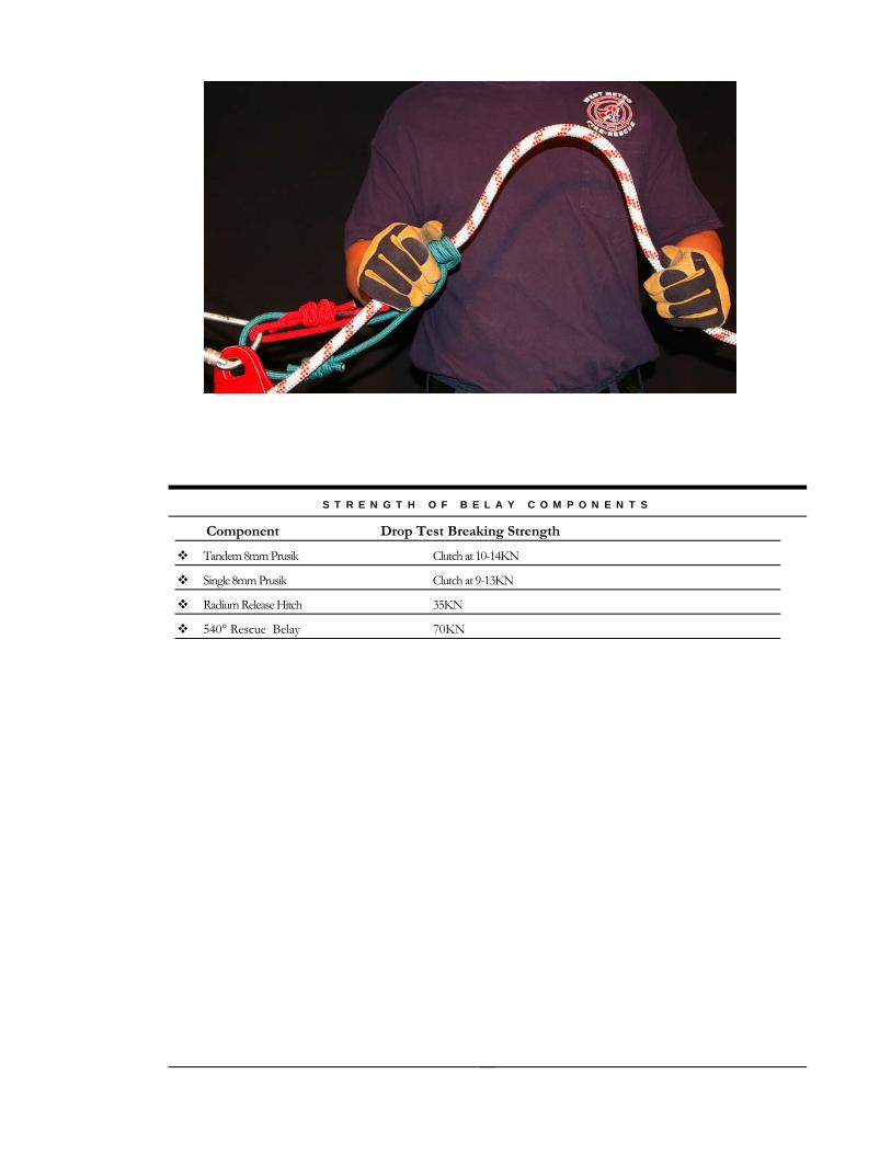
S T R E N G T H O F B E L A Y C O M P O N E N T S
Component Drop Test Breaking Strength
Tandem 8mm Prusik Clutch at 10-14KN
Single 8mm Prusik Clutch at 9-13KN
Radium Release Hitch 35KN
540° Rescue Belay 70KN
43
Hauling Systems O B J E C T I V E S
Define the types of hauling systems
Understand the “Tension” or “T-method” for calculating theoretical mechanical advantage
Hauling systems are used in situations where it is not possible or practical to lower once a rescuer has secured the patient. Some examples are: cannons, gorges, rivers, caves, mine shafts and other confined spaces.
ulley systems are often used to create mechanical system and make ideal hauling systems. A ulley system’s ideal mechanical advantage (IMA) is expressed as a ratio of the amount of output force the amount of input force (i.e. 3:1 or “3 to 1”). The input force is the tension that you apply to
ssed as one. IMA assumes that there are no losses in the pulley system due to pulley friction, ropes rubbing, bending or unbending.
I und stand ug a pu y system. Mechanical a y in reasing the num he initial input of one is applied to the load. This can be accomplished many ways through di em and rigging techniques.
C e l Me hanical Advantage A common method used to calculate the IMA is referred to as the tension method, or T-method. The ey to understanding the T-method is in recognizing what happens to the tension in the rope as it
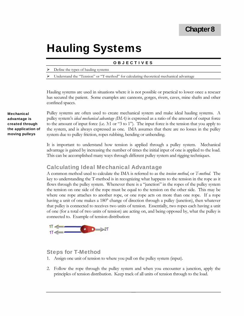
flows through the pulley system. Whenever there is a “junction” in the ropes of the pulley system the tension on one side of the rope must be equal to the tension on the other side. This may be where one rope attaches to another rope, or one rope acts on more than one rope. If a rope having a unit of one makes a 180° change of direction through a pulley (junction), then whatever that pulley is connected to receives two units of tension. Essentially, two ropes each having a unit of one (for a total of two units of tension) are acting on, and being opposed by, what the pulley is connected to. Example of tension distribution:
Pptothe system, and is always expre
Chapter 8
Mechanical advantage is created through the application of moving pulleys
t is important to er how tension is applied thro h lledvantage is gained b c ber of times t
fferent pulley syst
alculating Id a c
k
Steps for T-Method 1. Assign one unit of tension to where you pull on the pulley system (input).
2. Follow the rope through the pulley system and when you encounter a junction, apply the principles of tension distribution. Keep track of all units of tension through to the load.
44

3. Total all units of tension that reach the load; the IMA is the ratio between this total and the initial one unit of tension (i.e. 3:1, 6:1).
Types of Pulley System
are moving at e same rate. An example of a simple system would be a 3:1, as shown in the example below:
s & Applying T-Method Simple Pulley System A simple pulley system is where all ropes are under tension, and all traveling pulleys th
Compound Pulley System A compound pulley system is essentially a simple pulley system acting on another simple pulley system. Pulleys may travel at different speeds and in different directions, based on the IMA of each simple pulley system. An example is a compound 9:1 as shown below:
Complex Pulley System A complex pulley system is defined as a system that is neither simple nor compound. These types of systems may have limited applications in rope rescue scenarios.
Mechanical Advantage Use As a rule of thumb, never exceed a value of “18” on a mechanical advantage system. This is
lculated by multiplying the number of haulers times the amount of TMA. Example:
9 haulers on a 3:1 system = 18
ca
3 haulers on a 6:1 system = 18
45

Resources www.coloradotechrescue.com
www.pmirope.com
www.animatedknots.com
www.riggingforrescue.com
http://www.homelandsecurity.az.gov/TS_Comm.htm
46

References
Animated Knots By Grog. (2007, January 14). Search and Rescue Knots.
dknots.com/indexrescue.php?LogoImage=LogoGrog.jpg&
knots.com
Brow lbany, NY: Delmar Thomson
Learning.
Gibbs, M. (2002, September 24). Rigging for Rescue. Seminar handouts
Larson, A. (1990). Rescue systems testing background and summary. Invemere, B.C., Canada:
BCCTR.
Lipke, R. (1999). Technical rescue riggers guide. Bellingham, WA: Conterra.
National Fire Protection Agency (1999). NFPA 1670 standard on operations and training for
technical rescue. Quincy, MA: NFPA.
National Fire Protection Agency (2001). NFPA 1983 standard for fire service life safety rope and
system components. Quincy, MA: NFPA.
National Fire Protection Agency (2000). NFPA 1006 standard for rescue technician professional
qualifications. Quincy, MA: NFPA.
Smith, B., & Padgett, A. (1996). On rope (Rev. ed.). Huntsville, AL: National Speleological
Society. Vines, T., & Hudson, S. (2004). High angle rescue techniques (3rd ed.). St. Louis, MO: Elsevier Mosby.
//http://www.animate
Website=www.animated
n, M. G. (2000). Engineering practical rope rescue systems. A
47

Attachments
This page left intentionally blank
48
Colorado Technical Rescue Rope Rescue
Rappelling Commands and Safety Check
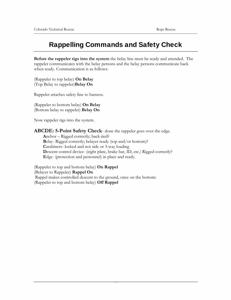
Before the rappeler rigs dy and attended. The rappeler communicates with the belay persons and the belay persons communicate back when ready. Communication is as follows: (Rappeler to top belay) On Belay (Top Belay to rappeler)Belay On Rappeler attaches safety line to harness. (Rappeler to bottom belay) On Belay (Bottom belay to rappeler) Belay On Now rappeler rigs into the system. ABCDE: 5-Point Safety Check ge. Anchor – Rigged correctl Belay- Rigged correctly; belayer ready (top and/or bottom)? Carabiners- locked and not side or 3-way loading Descent control device- (eight plate, brake bar, ID, etc.) Rigged correctly? Edge- (protection and personnel) in place and ready. (Rappeler to top and bottom belay) On Rapp(Belayer to Rappeler) Rappel On Rappel makes controlled descent to the ground, once on the bottom: (Rappeler to top and bottom belay) Off Rapp
into the system the belay line must be rea
- done the rappeler goes over the edy; back-tied?
el
el
49
Colorado Tech Rescue Rope Rescue
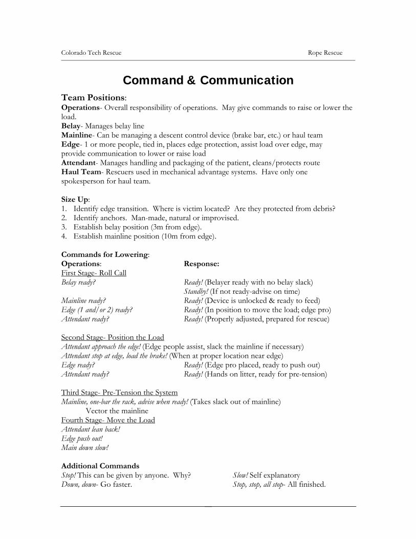
Command & Communication Team Positions:
ng a descent control device (brake bar, etc.) or haul team ces edge protection, assist load over edge, may
r raise load - Manages handling and packaging of the patient, cleans/protects route
al advantage systems. Have only one okesperson for haul team.
m located? Are they protected from debris? atural or improvised.
. Establish belay position (3m from edge).
Operations- Overall responsibility of operations. May give commands to raise or lower theload. Belay- Manages belay line Mainline- Can be managiEdge- 1 or more people, tied in, plaprovide communication to lower oAttendantHaul Team- Rescuers used in mechanicsp Size Up: 1. Identify edge transition. Where is victi2. Identify anchors. Man-made, n34. Establish mainline position (10m from edge). Commands for Lowering: Operations: Response: First Stage- Roll Call Belay ready? Ready! (Belayer ready with no belay slack)
Standby! (If not ready-advise on time) vice is unlocked & ready to feed)
Ready! (In position to move the load; edge pro) ed for rescue)
Mainline ready? Ready! (DeEdge (1 and/or 2) ready? Attendant ready? Ready! (Properly adjusted, prepar Second Stage- Position the Load
(Edge people assist, slack the mainline if necessary) Attendant stop at edge, load the brake! (When at proper location near edge) Edge ready? Ready! (Edge pro placed, ready to push out) Attendant ready? Ready! (Hands on litter, ready for pre-tension)
hird Stage- Pre-Tension the System
Attendant approach the edge!
T Mainline, one-bar the rack, advise when ready! (Takes slack out of mainline) Vector the mainline Fourth Stage- Move the Load Attendant lean back! Edge push out! Main down slow! Additional Commands Stop! This can be given by anyone. Why? Slow! Self explanatory Down, down- Go faster. Stop, stop, all stop- All finished.
50
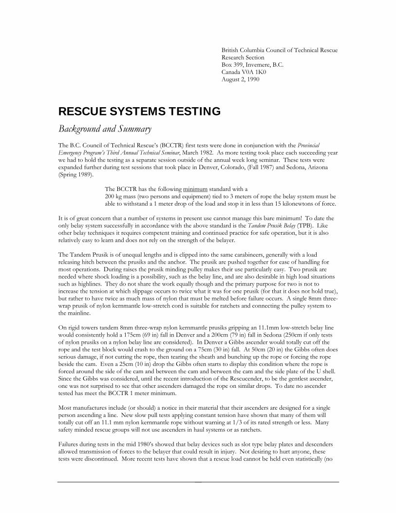
British Colum f Technical Resbia Council o cue Research Section Box 399, Invemere, B.C.
CUE SYSTEMS TESTING
sts were done in conjunction with the Provincial eding year w re
na, Arizona
The BCCTR has the following minimum
Canada V0A 1K0 August 2, 1990
RESBackground and Summary The B.C. Council of Technical Rescue’s (BCCTR) first teEmergency Program’s Third Annual Technical Seminar, March 1982. As more testing took place each succe
testswe had to hold the testing as a separate session outside of the annual week long seminar. These eexpanded further during test sessions that took place in Denver, Colorado, (Fall 1987) and Sedo(Spring 1989). standard with a
st be force.
t manage this bare minimum! To date the standard is the Tandem Prusik Belay (TPB). Like
ther belay techniques it requires competent training and continued practice for safe operation, but it is also t rely on the strength of the belayer.
he same carabineers, generally with a load andling for
rusik are ons
d true), three-
m to e mainline.
ay line ly tests ff the
e rope eside the cam. Even a 25cm (10 in) drop the Gibbs often starts to display this condition where the rope is
n the cam and between the cam and the side plate of the U shell. be the gentlest ascender, . To date no ascender
um.
ude (or should) a notice in their material that their ascenders are designed for a single a line. New slow pull tests applying constant tension have shown that many of them will
.1 mm nylon kernmantle rope without warning at 1/3 of its rated strength or less. Many e groups will not use ascenders in haul systems or as ratchets.
1980’s showed that belay devices such as slot type belay plates and descenders sult in anyone, these
(no
200 kg mass (two persons and equipment) tied to 3 meters of rope the belay system mup it in less than 15 kilonewtons of able to withstand a 1 meter drop of the load and sto
It is of great concern that a number of systems in present use cannoonly belay system successfully in accordance with the above orelatively easy to learn and does no
unequal lengths and is clipped into tThe Tandem Prusik is of releasing hitch between the prusiks and the anchor. The prusik are pushed together for ease of hmost operations. During raises the prusik minding pulley makes their use particularly easy. Two pneeded where shock loading is a possibility, such as the belay line, and are also desirable in high load situatisuch as highlines. They do not share the work equally though and the primary purpose for two is not to
slippage occurs tincrease the tension at which o twice what it was for one prusik (for that it does not holmbut rather to have twice as much mass of nylon that must be melted before failure occurs. A single 8m
wrap prusik of nylon kernmantle low-stretch cord is suitable for ratchets and connecting the pulley systeth On rigid towers tandem 8mm three-wrap nylon kernmantle prusiks gripping an 11.1mm low-stretch belwould consistently hold a 175cm (69 in) fall in Denver and a 200cm (79 in) fall in Sedona (250cm if on
t oof nylon prusiks on a nylon belay line are considered). In Denver a Gibbs ascender would totally curope and the test block would crash to the ground on a 75cm (30 in) fall. At 50cm (20 in) the Gibbs often does serious damage, if not cutting the rope, then tearing the sheath and bunching up the rope or forcing thbforced around the side of the cam and betweeSince the Gibbs was considered, until the recent introduction of the Rescucender, to
enders damaged the rope on similar dropsone was not surprised to see that other asctested has meet the BCCTR 1 meter minim Most manufactures inclperson ascendingtotally cut off an 11afety minded rescus
Failures during tests in the mid allowed transmission of forces to the belayer that could re injury. Not desiring to hurttests were discontinued. More recent tests have shown that a rescue load cannot be held even statistically
51

fall involved) by many slot type belay plates. Manufactures of ththe units efficiency (output/input) with representative ropes so the purchaser can see if it is below the .05 efficiency level the BCCTR recommends as a ceiling for belay de e loads. When tested in Denver with the LR Hitch between the tandem 8mm prusiks and the anchor the combination
nce held a 300 cm fall (fall factor of 1). In Sedona this same combination held a 300 cm fall with some aterials but not with others. Without an LR Hitch wet prusiks managed a 275 cm fall and wide spaced
prusiks 300 cm. One may feel that a larger diameter prusik may be desirable since melting does occur within t been confirmed. It appears (all else equal) r, which generates more heat. There may be
e material can be found) on 12.7 mm belay lines but further testing is t less stretch in a larger diameter rope will mean that more of the energy
f the fall must be absorbed by the belay rather than in the rope itself.
as itan polyester Prusik Rope has a tendency to grip too well and often fails instead of sliding.
rratic results suggest that one should also stay away from ropes coated with Rhino-Kote ™ if you intend to se prusi for bel e materials perform better as a
belay than mechan
siks tighten in to the diameter of the rope (within reason) and grip all around its surface. When slippage
y
sfully arrested by the use of mechanical pe clamps, descenders or slot type belay plates used on “icy” ropes are not available either.
),
et me know if you have questions, concerns or corrections.
ese devices should be encouraged to document
vices to be used with rescu
om
the prusiks when such severe falls are arrested, however this has nothat larger diameter prusiks do not grip quite as well and slip furthea case for using 9mm prusiks (if suitablnecessary. One must keep in mind thao I will caution you that texture, stiffness, and sheath thickness etc. of the prusik material can have some effect on its performance. Our supply for 8 mm nylon kernmantle accessory cord is the European manufactures such as Edelrid, Mammut, etc. And this is our present standard. Our tests indicate that other materials suchWellington-PurEu ks aying. All our information indicates that prusiks of suitabl
ical rope clamps even when wet or muddy.
Pruoccurs they generate an operating temperature that is suitable to the materials and energy absorption needs we are dealing with. The water seems to be driven off by the heat. This added energy outlet, for wet prusiks, maactually make the prusik stand up better. The behavior of prusiks on “icy” ropes has yet to be determined, however tests results confirming that falling rescues loads can be succesro While it is true that different materials give different results, this must not be blown out of proportion. Assuming that the material is not too stiff to work well as a haul or ratchet prusik, is sufficiently large (8 mmand two 3-wrap prusiks are used in tandem, then it can be said that you have a better chance of catching a severe fall with prusiks (regardless of whether they are nylon, perion, polyester, braid on braid, plaited, kernmantle, 3 strand twisted) than with mechanical rope clamps or slot type belay plates. And when using nylon kernmantle low-stretch prusiks on a nylon kernmantle low-stretch belay line the improvement is significant. L Submitted by, Arnör Larson (Copyright 1990 transcribed 2005) Note: This sheet is a brief summary and does not give the details necessary to operate a Tandem Prusik Belay safely
52

Material Strengths Card
MATERIAL STRENGTH 6mm Cord 7.5 KN 7mm Cord 10 KN 8mm Cord 13-15 KN 11mm Cord 30 KN 13mm Cord 40 KN Aluminum Carabiner 22-30 KN Steel Carabiner 40 KN Large Diameter Pulley 32 KN PMP 36 KN Brake Rack 46-56 KN (breaks rope @ 26 KN)25mm Tubular Webbing 18 KN 25mm Flat Webbing 26 KN W2P1 (Tub/Flat) 24-26 KN/32 KN W3P2 (Tub/Flat) 35-40 KN/46 KN Radium Release (RRH) 35+ KN 540 Rescue Belay 70 KN (NFPA -36 KN) Tandem Prusik Clutch at 10-14 KN Single Prusik Clutch at 9-13 KN
53