Root-end management: resection, cavity preparation, and ... · Root-end management: resection,...
21
Root-end management: resection, cavity preparation, and material placement JOHN J. STROPKO, GLEN E. DOYON & JAMES L. GUTMANN Current protocols for root-end management in apical microsurgery are described. The dramatic increase in light and magnification as the advent of the surgical operating microscope (SOM) for use in endodontic apical surgery has caused a renewed examination of the rationale, indications, techniques, instrumentation, and materials for root- end procedures. Additional research and increased use of the SOM in endodontic surgery have elucidated many shortcomings of previous techniques. Root-end resection, root-end bevel, root-end preparation, and root-end filling are discussed. The steps necessary to achieve a predictable result in performing surgical root-end procedures using the enhanced vision of the SOM are presented. Root-end resection – rationale Review of the literature over the last decade supports the following common indications for resection of the apical portion of the root during periradicular surgery (1) (Fig. 1): Removal of pathologic processes – Some examples include symptomatic fractured root apices, sus- pected contaminated apices (retained microorgan- isms and biofilms), root apices with tenaciously attached pathologic tissue, and removal of foreign material in the apical portion of the canal. Removal of anatomic variations – The anatomic variations most commonly encountered are apical deltas, accessory canals, apical canal bifurcations, severe curves, lateral canals, and calcifications. Removal of operator errors in non-surgical treatment – These include complications such as ledges, block- ages, zips, perforations, and separated instruments. Enhanced removal of the soft tissue lesion – Root resection is often necessary to gain access to deeply placed soft tissue around the root in order to secure an adequate biopsy. Access to the canal system – In cases where the major canal systems are blocked with, for example, a post- core restoration, and the apical portion of the canal has not been properly cleaned, shaped, or obtu- rated, root-end resection (RER) may be necessary to manage the untreated portion of the root canal system (Fig. 2). Evaluation of the apical seal – This can occur in conjunction with the previous indication, when the canal obturation is questionable, yet access to the entire root system with non-surgical retreatment is impractical or impossible. Creation of an apical seal – This is one of the most common indications for RER. In cases where the root canal treatment has already been performed non-surgically, RER may be necessary to create an environment for access and vision so that an adequate apical seal can be achieved. Reduction of fenestrated root apices – This situation is most common in maxillary teeth, but can occur anywhere in the dentition. Possible contributing factors include age, anatomical anomalies, ortho- dontics, and trauma. Evaluation for aberrant canals and root fractures – In some cases, the root canal obturation is judged to be satisfactory and the etiology of failure is not clinically or radiographically evident. RER will potentially expose these aberrant canal commu- nications, complete, or incomplete vertical frac- tures, which can be detected on a stained root-end bevel (REB). (See following section on staining.) 131 Endodontic Topics 2005, 11, 131–151 All rights reserved Copyright r Blackwell Munksgaard ENDODONTIC TOPICS 2005 1601-1538
Transcript of Root-end management: resection, cavity preparation, and ... · Root-end management: resection,...

Root-end management: resection,cavity preparation, and materialplacementJOHN J. STROPKO, GLEN E. DOYON & JAMES L. GUTMANN
Current protocols for root-end management in apical microsurgery are described. The dramatic increase in light
and magnification as the advent of the surgical operating microscope (SOM) for use in endodontic apical surgery
has caused a renewed examination of the rationale, indications, techniques, instrumentation, and materials for root-
end procedures. Additional research and increased use of the SOM in endodontic surgery have elucidated many
shortcomings of previous techniques. Root-end resection, root-end bevel, root-end preparation, and root-end
filling are discussed. The steps necessary to achieve a predictable result in performing surgical root-end procedures
using the enhanced vision of the SOM are presented.
Root-end resection – rationale
Review of the literature over the last decade supports
the following common indications for resection of the
apical portion of the root during periradicular surgery
(1) (Fig. 1):
� Removal of pathologic processes – Some examples
include symptomatic fractured root apices, sus-
pected contaminated apices (retained microorgan-
isms and biofilms), root apices with tenaciously
attached pathologic tissue, and removal of foreign
material in the apical portion of the canal.
� Removal of anatomic variations – The anatomic
variations most commonly encountered are apical
deltas, accessory canals, apical canal bifurcations,
severe curves, lateral canals, and calcifications.
� Removal of operator errors in non-surgical treatment –
These include complications such as ledges, block-
ages, zips, perforations, and separated instruments.
� Enhanced removal of the soft tissue lesion – Root
resection is often necessary to gain access to deeply
placed soft tissue around the root in order to secure
an adequate biopsy.
� Access to the canal system – In cases where the major
canal systems are blocked with, for example, a post-
core restoration, and the apical portion of the canal
has not been properly cleaned, shaped, or obtu-
rated, root-end resection (RER) may be necessary
to manage the untreated portion of the root canal
system (Fig. 2).
� Evaluation of the apical seal – This can occur in
conjunction with the previous indication, when the
canal obturation is questionable, yet access to the
entire root system with non-surgical retreatment is
impractical or impossible.
� Creation of an apical seal – This is one of the most
common indications for RER. In cases where the
root canal treatment has already been performed
non-surgically, RER may be necessary to create an
environment for access and vision so that an
adequate apical seal can be achieved.
� Reduction of fenestrated root apices – This situation
is most common in maxillary teeth, but can occur
anywhere in the dentition. Possible contributing
factors include age, anatomical anomalies, ortho-
dontics, and trauma.
� Evaluation for aberrant canals and root fractures –
In some cases, the root canal obturation is judged
to be satisfactory and the etiology of failure is not
clinically or radiographically evident. RER will
potentially expose these aberrant canal commu-
nications, complete, or incomplete vertical frac-
tures, which can be detected on a stained root-end
bevel (REB). (See following section on staining.)
131
Endodontic Topics 2005, 11, 131–151All rights reserved
Copyright r Blackwell Munksgaard
ENDODONTIC TOPICS 20051601-1538

The validity of these indications, and the rationale for
their use, resides in each individual case being treated.
RER – the bevel
Long bevel vs. short bevel
When the apical end of a root is removed, the remaining
surface of the root is described as having been
‘bevelled.’ The amount and degree of the resected
bevel are of utmost importance. The overall crown/
root ratio, presence of posts or other obstacles, root
anatomy, remaining crestal bone, and the periodontal
status of the tooth must be considered. If the bevel is
made in the traditional manner at a 20–451 bucco-
lingual incline, more of the palatal or lingual aspect of
the root will be left untreated (2–5). This situation
occurs when the surgeon is trying to be conservative in
order to maintain a more favorable crown/root ratio.
Because 98% of apical canal anomalies and 93% of
lateral canals system ramifications occur in the apical
Fig. 1. (A) Surgically exposed root apex with obviouslaceration of the root canal at the root end andoverextension of the filling material. (B) Root-endresection removing approximately 3 mm of the root apex.
Fig. 2. Double root canal systems in single roots. (A) Rootwith obturated canals; root had been placed in India inkdye for 5 days and cleared chemically. Note the complexityof the canal systems and the leakage pattern. Root-endresection (RER) would be necessary to remove theseirregularities. (B) Cleared extracted root with two canals.Note that both canals are not clean (brownish material),and that one canal is cleaned and shaped significantly shortof the desired length. Canal irregularities are present. RERof the apical 3 mm would be necessary to remove theseuncleaned areas and enable proper cleaning and sealing.
Stropko et al.
132

3 mm, it is essential that at least 3 mm of the root end is
removed (6–8). Long bevels require the removal of an
excessive amount of root structure to include the
lingual, or palatal 3 mm of the root apex. If the bevel is
closer to 01, more root structure can be conserved,
improving the crown/root ratio while meeting the
objective of removing the vast majority of apical
ramifications (Fig. 3).
The long bevel creates a spatial disorientation that is
often difficult to overcome regarding the true long axis
of the canal system (Fig. 4). As it is difficult to visualize
the long axis of the tooth, the subsequent root-end
preparation (REP) will usually not be within the long
axis of the canal. Failure to comprehend this concept is
the primary reason that perforations to the lingual, or
palatal, occur (9) (Fig. 5). Another consideration for
the 01 bevel is that the cavo-surface marginal dimen-
sions of the preparation will be considerably decreased,
therefore allowing an easier and more predictable seal.
A good axiom to consider is this: whatever the angle of
the bevel, it is almost always greater than it appears to
be (7, 9).
Knowledge of root anatomy is especially important
when there are more than two canals in one root. This
anatomical complexity was identified and delineated
over 100 years ago (10), and its implications in surgical
endodontics were highlighted 70 years ago (11) (Fig.
6). This occurs most commonly in maxillary premolars
and in the mesial roots of nearly all molars; however,
multiple canals can occur in any root (12–14).
Ideally, the short bevel (01) is as perpendicular to the
long axis of the tooth as possible in order to predictably
achieve several important criteria:
� Conservation of root length – When a long bevel
(20–451) is made, more tooth structure has to be
removed in order to expose the anatomical apex of
the tooth (5, 7, 9) (Fig. 7). With a long bevel, an
inordinate amount of root structure would have to
be removed in order to include the entire apical
3 mm.
� Less chance of missing lingual anatomy – The short
bevel allows inclusion of lingual anatomy with less
Fig. 3. The ‘long’ bevel (451) removes more root structureand increases the probability of overlooking importantlingual anatomy. The ‘shorter’ bevel (61) conserves rootstructure, maintains a better crown/root ratio, andincreases the ability to visualize important lingualanatomy.
Fig. 4. The ‘long’ bevel minimizes tooth structure to thelingual and makes it more difficult for the operator tovisualize the long axis of the tooth. Courtesy Dr Gary B.Carr, San Diego, CA, USA.
Fig. 5. (A) The ‘long,’ but conservative bevel of themesiobuccal (MB) root did not address the more thesecond mesiobuccal root canal (MB2) of this maxillaryfirst molar. (B) Not only was the MB2 canal completely‘missed’, but there was an inadvertent perforation of theMB root – and incomplete bevel of distobuccal (DB) rootend.
Root-end management
133

reduction. With the long bevel, there is a decreased
probability of encroachment on the lingual root
surface (Figs 2, 3 and 8, 9).
� A shorter cavo-surface margin – If multiple canals
are present, the distance between them will increase
as the angle of the bevel increases. As it is
recommended that the isthmus also be prepared, a
shorter bevel allows for a shorter cavo-surface
margin length in the completed REP (7).
� Less chance of an incomplete resection – The shorter
bevel makes it easier for the operator to resect the
root end completely and not leave a ‘lingual cusp,’
or incomplete resection (7–9, 15).
� Easier to detect multiple or aberrant canals – When
the short bevel is prepared, more lingual anatomy
can be accessed (7–9, 15).
� Less exposed dentinal tubules – As the dentinal
tubules are more perpendicularly oriented to the
long axis of the tooth, the short bevel will expose
fewer tubules (Fig. 10A). The long bevel opens more
tubules to be exposed to the environment, which can
allow more micro-leakage over a period of time.
Fig. 6. (A, B) Diagrams taken from Peter (11). These are drawings from the 1901 publication (10) by Gustav Prieswerkthat emphasized the complexity of the root canal systems located in roots with multiple canals.
Fig. 7. (A) The long bevel has a greater cavo-surface marginlength with a greater probability of leakage. (B) The shortbevel has a shorter cavo-surface margin length to seal and,therefore, decreases the chances of leakage. Courtesy DrGary B. Carr, San Diego, CA, USA.
Stropko et al.
134
� Easier to maintain REP within the long axis –
Instrumentation of the REP should be kept within
the long axis of the tooth to avoid unnecessary or
excess removal of radicular dentin. The longer the
bevel, the more difficult it is to envision and
maintain the REP within the long axis of the tooth
(7–9, 15) (Fig. 10B).
� Easier to include the isthmus in the REP if multiple
canals are present in a single root – The cleaning and
preparation of the isthmus that usually exists
between the canals whether or not it is visible after
the REB is very important. When there are multiple
canals in a root, isthmus tissue is present 100% of
the time at the 4 mm level (16). The short bevel
facilitates the isthmus preparation by allowing a
better ‘mental picture’ of the long axis of the tooth
(3, 7–9, 15).
Ideally, the root-end bevel (REB) is kept as short, or
as perpendicular to the long axis of the root as practical,
to facilitate complete resection and to expose the entire
apical canal system (3, 8, 9, 15). However, after positive
identification of the features on the surface of the bevel
has been made, it may be necessary to increase the angle
of bevel slightly, to achieve better access for instru-
ments, for improved vision, and/or to enhance
ergonomics for the patient and clinician.
Instrumentation and technique
After the cortical bone is removed to unroof the lesion,
the soft tissue is curetted from the crypt and the root-
end exposed. Adequate hemostasis is established if
necessary with appropriate hemostatic agents such as
ferric subsulfate (Cut-trol, Ichthys Enterprises, Mobile,
AL, USA), Telfa pads (Tyco Healthcare, Mansfield,
MA, USA), CollaCote (Sulzer Dental, Carlsbad, CA,
USA), calcium sulfate (LifeCore, Chaska, MN, USA),
SurgiPlaster (ClassImplant, Rome, Italy), CollaCote
Fig. 8. (A) Multiple apical foramina evident on the palatalsurface of the mesiobuccal (MB) root of a maxillary firstmolar. If this were resected with a long bevel, the canalsand exits would be overlooked. (B) Long bevel resectionof an MB root of a maxillary first molar shows the maincanal with gutta-percha and sealer; an isthmus is above itand a second, uncleaned canal is visible; then an isthmus isabove this second canal, and at the very tip of the resectedsurface an additional canal is present with gutta-percha.Management of this complex anatomy requires a muchshorter bevel and a significantly more resected root facearound the most palatally placed canal to permitthorough debridement and preparation.
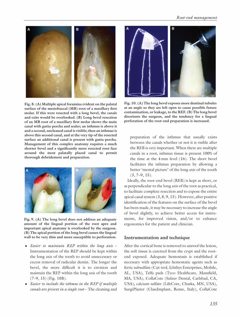
Fig. 9. (A) The long bevel does not address an adequateamount of the lingual portion of the root apex andimportant apical anatomy is overlooked by the surgeon.(B) The apical portion of the long bevel causes the lingualwall to be very thin and more susceptible to perforation.
Fig. 10. (A) The long bevel exposes more dentinal tubulesat an angle so they are left open to cause possible futurecontamination, or leakage, to the REF. (B) The long beveldisorients the surgeon, and the tendency for a lingualperforation of the root-end preparation is increased.
Root-end management
135

(Integrat, Plainsboro, NJ, USA), and the root end is
resected as quickly and efficiently as possible.
Although many instruments and burs are available to
complete the RER and REB, there is no need to
complicate a rather straightforward procedure. Essen-
tially, there are only three surgical length burs necessary
to accomplish the required tasks regarding the RER
and REB. They are: (1) the #6 or #8 round bur (S. S.
White, Lakewood, NJ, USA), for osseous access and
gross removal of the apex; (2) the Lindemann bone bur
(Brasseler USA, Savannah, GA, USA), for rapid hard
tissue removal and cutting the initial root bevel; and (3)
the #1170 or #1171 bur (S. S. White), for refinement
of the bevelled surface (Fig. 11). Note that, removal of
a minimum of 3 mm of the root apex is necessary, as
most canal aberrations and/or abnormalities that may
have contributed to the unfavorable response to non-
surgical treatment are within this zone (6, 8, 15, 16).
A high-speed handpiece that has no air exiting from
the working end, such as a Palisades Dental Impact Air
45 handpiece (Star Dental, Lancaster, PA, USA) (Fig.
12), should be used to eliminate the possibility of air
emphysema or an air embolism beneath the flap in the
soft tissues (9, 17). For these reasons, a standard high-
speed handpiece should never be used.
As the anesthetized bone in the endodontic surgical
site has a temporary decrease in blood supply, it is more
sensitive to heat. Therefore, small changes in the
technical aspects of osseous removal may significantly
affect bone physiology and viability (1). Bonfield & Li
(18) reported that at temperatures from 1501C to
901C, there was an irreversible bone deformation
because of both a reorientation of the structure of
collagen and a weakening of the bonds between the
collagen and hydroxyapatite. These findings are con-
sistent with protein denaturation subsequent to a burn
injury. Eriksson and co-workers (19–23) noted that
above 401C, a hyperemia occurred as the blood flow
increased. At a thermal stimulus of 50–531C for 1 min,
there was blood flow stasis with ultimate death of the
vascular network within 2 days. Heating of bone to
601C, or more, resulted in permanent cessation of
blood flow and tissue necrosis.
Most studies using rotary instruments to generate
heat are confounded by such variables as speed of
drilling, pressure, air conduction, amount of coolant,
accumulation of chips and debris, and friction (1). In
any event, during the removal of osseous tissue,
adequate coolant must be applied and the cutting must
be performed with a light, brushing stroke. All burs
used in apical surgery must have shapes that cut sharply
and flutes that are far enough apart to shed debris and
avoid ‘clogging.’ Clogging can result in decreased
efficiency and unintentional over heating of tissue (24).
The use of diamond burs to remove osseous tissue is
not recommended because of their inefficiency and
tendency to overheat the osseous tissues. The excessive
heat causes necrosis, and can result in an extremely slow
healing rate (24, 25) Using newer burs with sharp
cutting edges will also improve efficiency and accuracy
while decreasing the chances of over heating the
osseous tissues.
During RER, REB, or the refinement of the bevel,
some new bleeding may occur. Hemostasis must be re-
established before continuing with further root-end
procedures as it is imperative that the operator
maintains complete control of the surgical environ-
ment. Note that it is of utmost importance to complete
one step fully before proceeding to another!
Fig. 11. Three essential surgical length burs willaccomplish all that is necessary to achieve an efficientroot-end resection and refinement of the root-end bevel.(top) Lindemann bone cutting bur, (middle) #6 or #8Round bur, (bottom) #1170 or #1171 tapered-fissuresurgical length bur.
Fig. 12. The Impact Air 45 hand piece, with fiber optics,enhances efficiency, safety, and vision.
Stropko et al.
136

Methylene blue staining
After complete hemostasis is achieved, the bevelled
surface is ready for close inspection to be certain that
the REB has been properly completed. The resected
root end is rinsed and dried with an irrigator (Stropko
Irrigator, Vista Dental, Racine, WI, USA). The dried
surface is then stained with 1% methylene blue (MBS)
(8, 15, 26), which is allowed to remain undisturbed on
the resected surface for 10–15 s before once again
gently flushing with a sterile solution and drying with
an irrigator (Fig. 13A). As the MBS only discolors
organic material, it readily defines the anatomy within,
or around, the resected root end with a deep blue color.
If there are any fractures, tissue remnants in the
isthmus, or accessory canals present, the staining
process will greatly enhance the operator’s ability to
see them. When used properly, the MBS will delineate
the periodontal ligament and the operator can be sure
the apex has been completely resected (7) (Figs 13B
and C).
To obtain the maximum benefits of MBS, and to
inspect the bevelled surface thoroughly:
� the surface must be clean and dry before applying
the MBS;
� the MBS must be applied for 10–15 s to saturate the
surface and periodontal ligament;
� the surface must then be rinsed and dried thor-
oughly; and
� the REB should be examined using varying powers
of the SOM to see whether the RER is complete and
to insure that no abnormalities are present.
If after MBS there is an accessory canal present, the
easiest way to manage this anatomical entity is to bevel
past it and re-stain the surface to be sure that the defect is
completely eliminated. Alternately, the accessory canal
can be simply ‘troughed out,’ leaving the bevel as it is. If
a white background such as Telfa pads, CollaCote, or
calcium sulfate has been used to aid in hemostasis, or
vision enhancement, it should be replaced after staining
so that more light is reflected and vision renewed.
REP
Ultrasonic REP
Prior to ultrasonic instrumentation, various types of
rotary handpieces and ‘mini-burs’ were used. Because
of the necessity of using a ‘straight-in approach,’ it was
not possible to maintain the REP within the confines of
the long axis of the tooth and perforation of the lingual
surface could easily occur (see Fig. 10B). With the
advent of ultrasonic instrumentation, and the array of
angled tips currently available to the operator, it is now
possible to prepare a REP that will adequately and
predictably accept several different root-end filling
(REF) materials. The requirements for an REP include
(3, 7–9, 15):
� the apical 3 mm of the canal system is thoroughly
cleaned and shaped;
� the preparation is parallel to, and centered within,
the anatomic outline of the pulpal space;
� there is adequate retention form for the ref material
used,
� all isthmus tissue is removed; and
Fig. 13. (A) MBS is applied to the root-end bevel with amicro-applicator and allowed to remain on the surface fora short period of time. (B, C) Methylene Blue stainingenhances vision and defines possible fractures, accessories,lateral canals, isthmus tissue, contaminated root surface,periodontal ligaments, etc. Courtesy Dr Gary B. Carr, SanDiego, CA, USA.
Root-end management
137

� the remaining dentinal walls are not weakened.
The use of any one of a number of ultrasonic units will
allow the operator to complete the REP. The Satelec P-
5 (Mount Laurel, NJ, USA), EMS MiniEndo (Sybro-
nEndo, Orange, CA, USA), NSK (Brasseler, Savannah,
GA, USA), and Spartan (Obtura-Spartan, Fenton,
MO, USA) units are currently the most common and
all have a good reputation for performance, reliability,
and versatility (27). Some older EMS units only accept
tips made for its European thread, but the newer
models accept all of the common tips manufactured in
the United States.
There are a multitude of ultrasonic tips to choose
from and they come in all shapes and sizes. The first tips
made for endodontic apical microsurgery were the CT
series tips (PERF online at www.eie2.com or Sybro-
nEndo). They are made of stainless steel, very popular,
and are still in widespread use today (Fig. 14).
Some tips have special surface coatings to increase
their cutting efficiency. Diamond-coated tips are very
efficient and especially useful for removing gutta-percha
from the REP. Because of their efficiency, the surgeon
must avoid the tendency to overprepare the REP. In
addition, care must be exercised when using diamond-
coated tips because they can leave a heavily abraded
surface. The debris generated by these tips can collect in
these abrasions surface and if not removed can affect the
apical seal of the REF (28). The KiS ultrasonic tips
(Obtura-Spartan, Fenton, MO, USA) use port technol-
ogy and deliver a constant stream of water aimed
directly at the working end of the tip (8, 15) (Fig. 15).
Ticonium-coated tips (ProUltra, DENTSPLY Tulsa
Dental, Tulsa, OK, USA) are also very efficient. Like all
tips, they provide excellent vision for the operator
during the REP. These are just two of the hundreds of
tip designs available today in the worldwide market.
The most important consideration in the use of
ultrasonics is not the brand of the unit, or type of tip,
but how the instrument is used. The tendency for the
new operator is to use the ultrasonic in the same
manner (pressure-wise) as the hand piece. The secret is
an extremely light touch! In general, the lighter the
touch, the more efficient the cutting efficiency will be.
The correct amount of water is also important. If too
much spray is used, visibility and cutting efficiency are
both decreased. If too little water is used, the necessary
amount of cooling and rinsing of the debris will not
occur. This can cause overheating of the REP. Micro-
cracks and decreased vision may be the undesired result
(3, 7–9, 15). Numerous studies have shown that when
ultrasonic instrumentation is used properly, micro-
cracks are uncommon and should be of no concern to
the clinician (29–31). In addition, use of ultrasonic
instrumentation for REP, in place of the traditional, or
miniature, hand piece results in cleaner preps and fewer
perforations (30, 32). With the advent of ultrasonic
techniques for the preparation of the root end, the use
of a rotary hand piece is not advocated for root-end
cavity preparation in apical surgery.
Fig. 14. The first ultrasonic tips available – CT tips(www.eie2.com).
Fig. 15. The diamond-coated KiS ultrasonic tips are veryeffective and utilize newer vent technology. The waterspray is directed into the root-end preparation , efficientlyeliminating debris and helping to prevent overheating ofthe root end.
Stropko et al.
138

If the canal is large and/or filled with gutta-percha, a
diamond-coated anterior KiS tip can be used most
effectively. The various left- and right-angled tips are
necessary on occasion, but in most cases, the anterior-
type tips will suffice. The keys to successful preparation
are to apply the cutting tips slowly, using a gentle, light,
brushing motion.
The use of ultrasonic instrumentation is especially
useful in the preparation of an isthmus between two
canals present in one root. This is a commonly required
procedure during apical microsurgery. For example,
two canals can be present as much as 93% of the time in
the mesiobuccal root of the maxillary first molars, and
59% in maxillary second molars (12, 15, 34). Following
RER and visualization of the resected surface, two
canals with a uniting isthmus are usually visible (Fig.
16). For this reason, it is important to routinely prepare
the isthmus, whether it is defined by staining, or not,
because if the isthmus is just coronal to the bevelled
surface, post-surgical remodelling of the bevelled root
surface may expose the entire canal system to the
periradicular tissues. If the non-surgical root canal
treatment fails to clean the canal system thoroughly or
coronal leakage is present, failure may ensue (Fig. 17).
A good rule to follow is to always prepare an isthmus
when there are two canals in one root.
For the preparation of an isthmus, a CT-X explorer
(SybronEndo), or a sharp restorative chisel (1) may be
used to ‘scratch’ a ‘tracking groove’ between the canals.
With the water spray turned off, a CT-1 tip (Sybro-
nEndo), or any sharp, pointed ultrasonic tip can be
used, at low power, to deepen the tracking groove. Not
using a water spray allows excellent vision for the
creation of the ‘tracking groove,’ but the groove should
only be deepened enough without the water spray to
make it more definitive and easy to follow. The water
spray should be resumed as soon as possible to allow for
appropriate cooling and cleaning of the REP.
Fig. 16. After root-end resection and visualization of theresected surface, two canals with a uniting isthmus areusually visible and need to be addressed.
Fig. 17. When the isthmus is just coronal to the bevelledsurface, the isthmus must be prepared or thecontaminated pulp tissue just beneath the surface willnot be eliminated. Postsurgical remodelling of thebevelled root surface could possibly result in the entirecanal system becoming susceptible to bacterial invasion.
Root-end management
139

If difficulty is experienced when trying to establish a
tracking groove, the ‘dot technique’ may be used. With
the CT-1 tip inactivated and no water spray, place the
pointed tip exactly where desired and just lightly ‘tap’
the rheostat for an instant. The process is repeated
again, and again, as many times as necessary, until there
are a series of ‘dots’ created on the isthmus. It is then a
simple matter of connecting the dots to create the
initial ‘tracking groove’ as described in the preceding
paragraph (Fig. 18). The accuracy of cutting is then
maintained and the probability of ‘slipping off’ a small,
or thin, bevelled surface is eliminated.
After the groove is deep enough to guide the tip, the
water spray is turned back on and the preparation is
deepened to 3 mm while using a similar small, pointed
tip. Then, a larger and more efficient coated tip is used
to finish the walls and flatten out the floor of the REP to
the desired finish.
Of particular interest in the development of the apical
preparation is the buccal aspect of the internal wall of
the prep. Often, this area is not cleaned adequately
because of the angulations of the ultrasonic tip within
the canal system (Fig. 19). If there is some gutta-percha
‘streaming up’ the side of the wall, it is usually very time
consuming, or futile, to remove this gutta-percha with
an ultrasonic tip. The most effective way to finish the
REP is to use a small plugger and fold the gutta-percha
coronally, so the wall is clean once more.
A clean and dry apical root-end cavity preparation is
essential for good visibility when using the SOM.
Throughout the process, and after completion of the
REP, the cavity should be rinsed and dried with a small
irrigator/aspiration tip if possible. If a 25- or 27-
gauge-irrigating needle has been ‘pre-bent’ to a similar
shape as the ultrasonic tip used for the REP, the
ergonomics of using the irrigator will be more efficient
(Fig. 20). Subsequently, the cavity is inspected using
various levels of magnification and sizes of micro-
mirrors (Fig. 21) to confirm that the preparation is
within the long axis of the canal system and all debris
has been removed (Fig. 22). As an alternative, some
surgeons choose to use small segments of paper points
to dry the cavity; however, this may leave particles of
paper in the preparation or may fail to provide a
thorough drying in all dimensions.
The smear layer consists of organic and inorganic
substances, including fragments of odontoblastic pro-
cesses, microorganisms, and necrotic materials (35).
The presence of a smear layer prevents penetration of
intracanal medication into the irregularities of the root
canal system and the dentinal tubules and also prevents
complete adaptation of obturation materials to the
prepared root canal surface (36). If the surgeon is
satisfied that all other requirements for the REP have
Fig. 18. Left to right: ‘tapping’ the rheostat until a seriesof ‘dots’ are created on the isthmus as a guide. It is then asimple matter of connecting the dots to create the initial‘tracking groove’ to prevent inadvertent ‘slipping-off’from the desired isthmus track.
Fig. 19. Close attention must be given to the buccal wallof the root-end preparation. There is a tendency for debris(in this case, gutta-percha) to collect there while preparingthe REP and can be easily overlooked. Courtesy Dr GaryB. Carr, San Diego, CA, USA.
Stropko et al.
140

been met, the smear layer can be effectively removed by
etching with either 10% citric acid gel (Ultradent, Salt
Lake City, UT, USA), 17% EDTA (Pulpdent, Water-
town, MA, USA), BioPuret (DENTSPLY Tulsa
Dental), or 35% phosphoric acid gel (Ultra-Etch,
Ultradent) (36–38). After etching, the REP is again
thoroughly rinsed, dried, and re-examined under
varying powers of magnification (Fig. 23).
The underlying reason for endodontic failures is
almost invariably because of persistent infection of the
root canal space (39). In the majority of cases requiring
non-surgical retreatment, Enterococcus faecalis is the
main and persistent microbial species (40–44). If the
vast majority of teeth requiring endodontic surgery do
not responding favorably to previous non-surgical
endodontic treatment, it is imperative that treat-
ment be directed at eradicating bacterial infection
including E. faecalis from within the REP. Two percent
Fig. 20. ‘Pre-bending’ of a 25- or 27- gauge irrigatingneedle to a shape similar to the ultrasonic tip used for theroot-end preparation; the ergonomics of using theirrigator will be more efficient.
Fig. 21. Various sizes and shapes of micro-mirrors areused to monitor the progress of the entire root-endprocedure.
Fig. 22. The Stropko irrigator can direct a precise streamof water or air into the root-end preparation (REP),enhancing the inspection process. (A) Water is used toflush out debris; then, (B) air is used to dry the REP forbetter vision, and (C) the clean and dry REP is ready forinspection.
Fig. 23. SEM of an apical root cavity that has beensubjected to acid etching using 10% citric acid combinedwith 3% Fe2Cl3) ( � 420). Note the patent dentinaltubules and clean walls. Photo previously unpublishedused to support data found in (38).
Root-end management
141
chlorhexidine (CHX) gluconate is an effective anti-
microbial irrigating agent for this purpose, and is
available as a liquid or gel (Ultradent) (45–50). Once
the REP has been cleaned, dried, thoroughly inspected,
and the smear layeres removed, it should be irrigated
with 2% CHX liquid for 15 s or 2% CHX gel for 1 min
(47), then once again, thoroughly rinsed and dried.
The use of the CHX in a gel, rather than the liquid, may
take slightly more time but, the surgeon has better
control over its placement. The REP is now complete
and ready to be filled (Fig. 22C).
REF
Filling materials
At this point in the microsurgical procedure, the tissues
have been retracted, bleeding in the surgical crypt is
well managed, and the REP is ready to fill. The ideal
material for use as an REF should meet the following
requirements (8, 9, 15):
1. Provide for easy manipulation and placement with
adequate working time.
2. Maintain dimensional stability after being inserted.
3. Seal the REP completely.
4. Conform and adapt easily to the various shapes and
contours of the REP.
5. Be biocompatible and promote cementogenesis.
6. Be non-porous and impervious to all periapical
tissues and fluids.
7. Be insoluble in tissue fluids, not corrode or oxidize.
8. Be non-resorbable.
9. Be unaffected by moisture.
10. Be bacteriostatic, or not encourage bacterial growth.
11. Be radiopaque, or easily discernable on radiographs.
12. Not discolor tooth structure of the surrounding
tissues.
13. Be sterile, or easily and quickly sterilizable
immediately before insertion.
14. Be easily removed if necessary.
15. Be non-carcinogenic, and non-irritating to the
periapical tissues.
There are several materials currently available for the
REF, each having been used with varying degrees of
success (51–58). They include, among many others,
amalgam, IRM (DENTSPLY Caulk, Milford, DE,
USA), Super-EBA (S-EBA, Bosworth, Skokie, IL,
USA), Optibond (Kerr, Orange, CA, USA), Geristore
(DenMat, Santa Maria, CA, USA), and, most recently,
mineral trioxide aggregate (Pro Roott MTA, DENTS-
PLY Tulsa Dental).
Amalgam
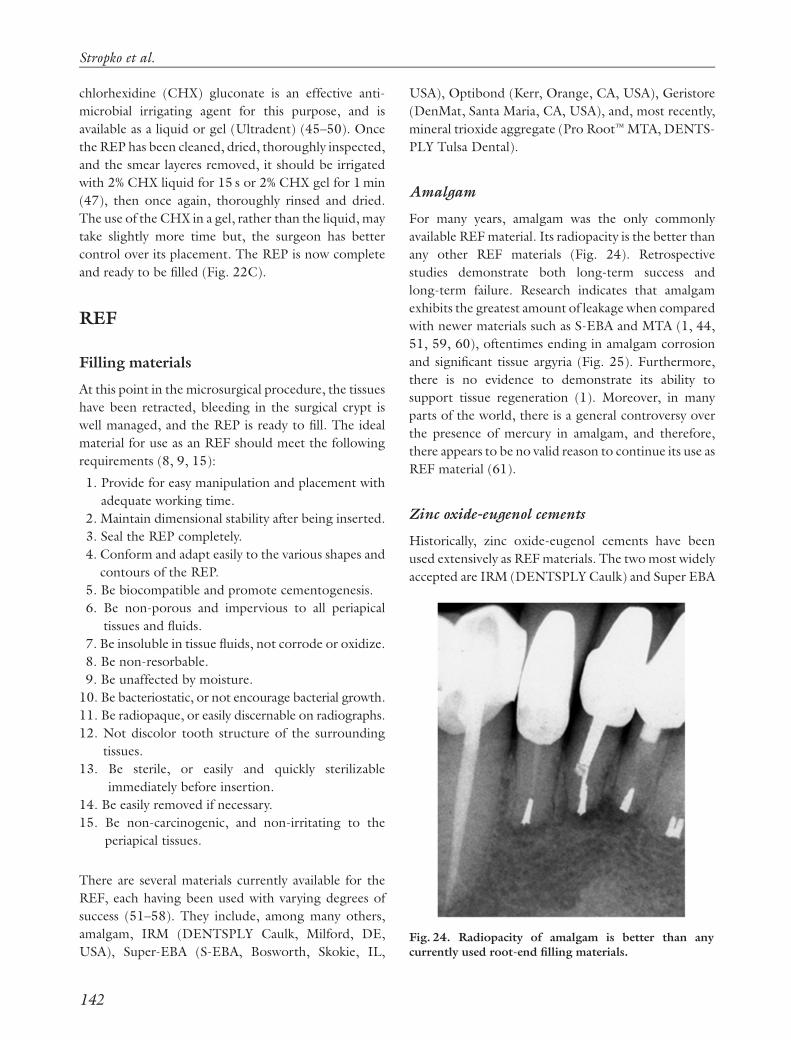
For many years, amalgam was the only commonly
available REF material. Its radiopacity is the better than
any other REF materials (Fig. 24). Retrospective
studies demonstrate both long-term success and
long-term failure. Research indicates that amalgam
exhibits the greatest amount of leakage when compared
with newer materials such as S-EBA and MTA (1, 44,
51, 59, 60), oftentimes ending in amalgam corrosion
and significant tissue argyria (Fig. 25). Furthermore,
there is no evidence to demonstrate its ability to
support tissue regeneration (1). Moreover, in many
parts of the world, there is a general controversy over
the presence of mercury in amalgam, and therefore,
there appears to be no valid reason to continue its use as
REF material (61).
Zinc oxide-eugenol cements
Historically, zinc oxide-eugenol cements have been
used extensively as REF materials. The two most widely
accepted are IRM (DENTSPLY Caulk) and Super EBA
Fig. 24. Radiopacity of amalgam is better than anycurrently used root-end filling materials.
Stropko et al.
142

(S-EBS, Bosworth, Skokie, IL, USA). Dorn & Gartner
(57) reviewed REFs in 194 cases and evaluated the
success rates of S-EBA, IRM, and non-zinc high copper
amalgam. The success rates over a 10-year period were
reported to be 95% for EBA, 91% for IRM, and 75% for
amalgam. Tissue responses demonstrated repair as
opposed to regeneration, a response no different from
that observed with gutta-percha (58, 62). Both IRM
and S-EBA exhibit similar and favorable properties and
are clinically and histopathologically better than amal-
gam (9): some of these desirable properties include:
� ease of manipulation,
� adequate working time,
� dimensional stability,
� placement and ease of adaptation in the REPs,
� biocompatibility,
� imperviousness to tissue fluids,
� lack of corrosion or oxidation,
� unaffected by moisture,
� bacteriostatic,
� radiopaque,
� will not discolor tooth or surrounding tissues,
� easily removable,
� non-carcinogenic, and
� predictable over time.
When solubility was measured in a buffered phos-
phate solution, both IRM and S-EBA exhibited no
significant signs of disintegration after a 6-month
period (62). The addition of ortho-ethoxybenzoic acid
to the formulation of S-EBA decreased the amount of
the tissue-irritating eugenol in the liquid portion of the
formula to 37.5% vs. 99% eugenol in the IRM liquid
(63).
The ability to create a conservative, anatomically
correct REP with ultrasonic armamentarium de-
manded an alternative to amalgam as an REF material
and led to the popularity of S-EBA for this purpose.
While leakage patterns with the use of S-EBA as a filling
material following ultrasonic REPs were disturbing
(64), Rubinstein & Kim (65) reported the short-term
success of endodontic surgery using microsurgical
techniques and S-EBA as an REF. All 94 cases included
in the study were treated by a single clinician. Post-
operative radiographs were taken every 3 months for a
12-month period until the lamina dura was completely
restored, or the case had clinically failed. Successful
healing, evaluated radiographically, was 96.8%. In a
follow-up study (66), clinical examinations were made
and radiographs were evaluated 5–7 years after the cases
had first been considered healed. The same criteria for
evaluating successful healing were applied. Of the 59
cases examined, 54 (91.5%) remained healed, whereas
five (8.5%) showed evidence of apical deterioration.
The setting time of S-EBA can be unpredictable,
sometimes setting too quickly, and at other times,
taking too long. Ambient temperature and humidity
have a profound effect on the setting time. An increase
in temperature and/or humidity will shorten the
setting time (67–69). If the setting time needs to be
increased, the glass slab used to mix the S-EBA can be
cooled (70). The powder/water ratio of SEBA has to
be correct to ensure a thick, dough-like consistency,
permitting the assistant to roll it into a thin tapered
point. The ‘dough-like’ tapered end of the thin S-EBA
‘roll’ is segmented and passed to the doctor on the end
of either a small Hollenback, or spoon, and subse-
quently inserted into the REP, and gently compacted
coronally with the appropriate plugger. Two to five of
these small segments are usually necessary to overfill the
REP slightly.
After the REF is complete, an instrument and/or a
multi-fluted finishing bur are used to smooth the
surface, producing the final finish. It has been demon-
strated that the use of a 30-fluted tungsten carbide
finishing bur creates a better marginal adaptation to the
set S-EBA REF (71). An etchant may be used, once
again, to remove the ‘smear layer’ that was created
during the final finishing process. The removal of the
‘smear layer’ and the demineralization of the resected
Fig. 25. Corrosion and breakdown of apically placedamalgams often lead to extensive tissue argyria.
Root-end management
143

root end are thought to enhance cementogenesis, the
key to dentoalveolar healing, by exposing the collagen
fibrils of the dentin and cementum (72). However,
these data have only been supported in an animal
model, while the use of this approach has been shown
to be unfavorable for cementum deposition when MTA
was used as an REF material (73). For decades, the
presence of cemental deposition has been observed to
occur on exposed dentinal surfaces, which supports the
fact that acid etching of the surface may not be essential
to obtain full tissue regeneration. Further research to
provide clinical directives in this matter is warranted
(Fig. 26).
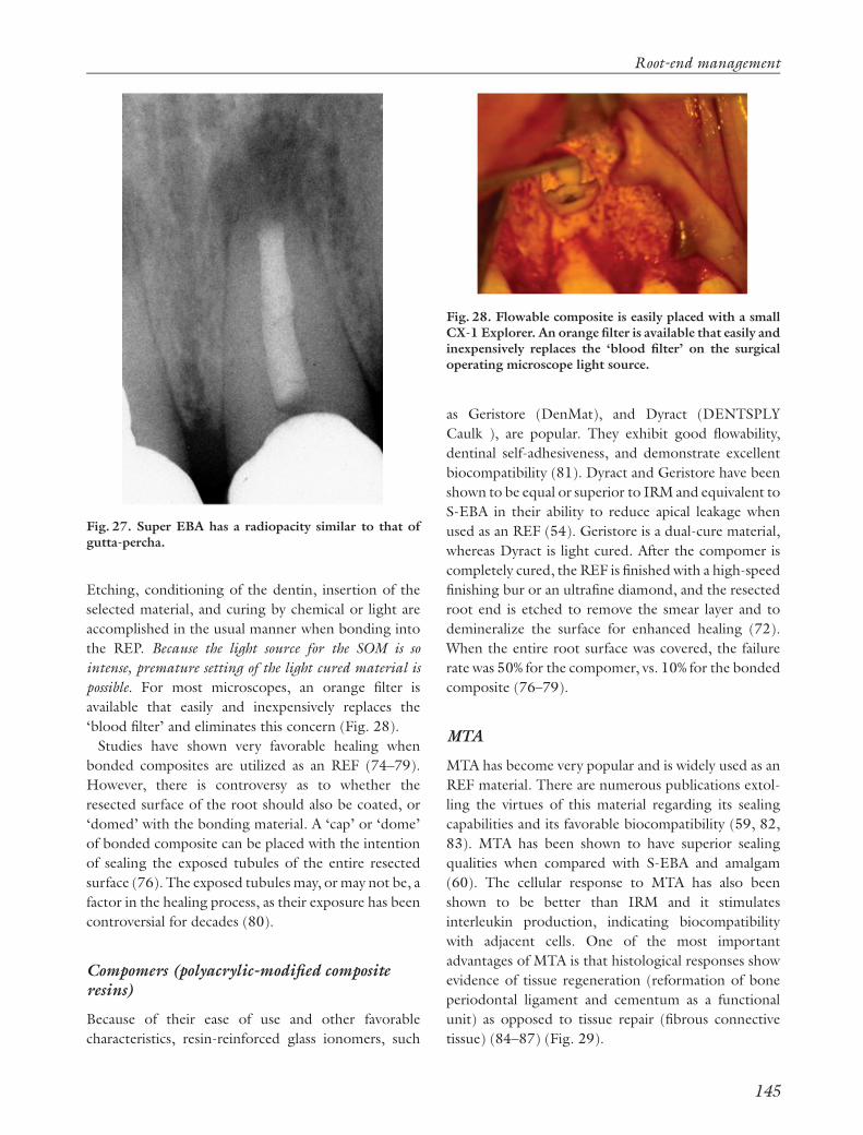
One of the earlier disadvantages of S-EBA was that it
was not as radiopaque as amalgam (Fig. 27). When
initially used in apical microsurgical procedures,
dentists sometimes had difficulty determining that an
REF had, indeed, been placed. This is no longer an
issue because the profession is more familiar with the
radiographic appearance of the various currently
accepted REF materials. Most newly advocated REF
materials have a radiographic appearance similar to S-
EBA and gutta-percha (74).
Composites
The use of dentin-bonding techniques requires un-
compromised control of the surgical crypt. Even a small
amount of contamination can cause a failure of the
bond to the dentin surface, resulting in micro-leakage
(75). The ability to have total control of moisture in the
apical surgical environment has led to the use of
bondable composite resins as REF materials. Theore-
tically, any composite can be used as an REF material,
whether it is auto, dual, or light cured. Two advantages
of dual cure materials are the increase in working time
and lowered requirement for direct light necessary to
initiate and complete the set.
Optibond (Kerr) is an example of a flowable, dual
cure hybrid composite that is easily placed into the REP.
Fig. 26. Evidence for the formation of cementum on exposed human dentine without the use of an acid etchant. (A)Photomicrograph of a retained fractured root tip from Boulger EP. Histologic studies of a specimen of fractured roots. JAm Dent Assoc 1928: 15: 1787–1779. The coronal portion of the root segment shows significant cement formation. (B,C) Histological demonstration of significant cementum formation on a resected root surface; tooth had a coronalfracture and was extracted. No etchant was used subsequently to remove the smear layer from the resected root end. Notehow the cementum ceased to form adjacent to the root-end filling in (C), which was a zinc oxide-eugenol-based product.
Stropko et al.
144
Etching, conditioning of the dentin, insertion of the
selected material, and curing by chemical or light are
accomplished in the usual manner when bonding into
the REP. Because the light source for the SOM is so
intense, premature setting of the light cured material is
possible. For most microscopes, an orange filter is
available that easily and inexpensively replaces the
‘blood filter’ and eliminates this concern (Fig. 28).
Studies have shown very favorable healing when
bonded composites are utilized as an REF (74–79).
However, there is controversy as to whether the
resected surface of the root should also be coated, or
‘domed’ with the bonding material. A ‘cap’ or ‘dome’
of bonded composite can be placed with the intention
of sealing the exposed tubules of the entire resected
surface (76). The exposed tubules may, or may not be, a
factor in the healing process, as their exposure has been
controversial for decades (80).
Compomers (polyacrylic-modified compositeresins)
Because of their ease of use and other favorable
characteristics, resin-reinforced glass ionomers, such
as Geristore (DenMat), and Dyract (DENTSPLY
Caulk ), are popular. They exhibit good flowability,
dentinal self-adhesiveness, and demonstrate excellent
biocompatibility (81). Dyract and Geristore have been
shown to be equal or superior to IRM and equivalent to
S-EBA in their ability to reduce apical leakage when
used as an REF (54). Geristore is a dual-cure material,
whereas Dyract is light cured. After the compomer is
completely cured, the REF is finished with a high-speed
finishing bur or an ultrafine diamond, and the resected
root end is etched to remove the smear layer and to
demineralize the surface for enhanced healing (72).
When the entire root surface was covered, the failure
rate was 50% for the compomer, vs. 10% for the bonded
composite (76–79).
MTA
MTA has become very popular and is widely used as an
REF material. There are numerous publications extol-
ling the virtues of this material regarding its sealing
capabilities and its favorable biocompatibility (59, 82,
83). MTA has been shown to have superior sealing
qualities when compared with S-EBA and amalgam
(60). The cellular response to MTA has also been
shown to be better than IRM and it stimulates
interleukin production, indicating biocompatibility
with adjacent cells. One of the most important
advantages of MTA is that histological responses show
evidence of tissue regeneration (reformation of bone
periodontal ligament and cementum as a functional
unit) as opposed to tissue repair (fibrous connective
tissue) (84–87) (Fig. 29).
Fig. 27. Super EBA has a radiopacity similar to that ofgutta-percha.
Fig. 28. Flowable composite is easily placed with a smallCX-1 Explorer. An orange filter is available that easily andinexpensively replaces the ‘blood filter’ on the surgicaloperating microscope light source.
Root-end management
145

Many clinicians complain of the unforgiving handling
characteristics of MTA. The correct powder/water
ratio is three parts powder to one part sterile aqueous
solution. After mixing for about 30 s, the material
should exhibit a putty-like consistency (88). If the
mixture is too wet, it acts like wet sand and ‘slumps,’
but when too dry, it has a ‘crumbly’ and unmanageable
texture, similar to that of dried mud. In either case,
when not mixed properly, MTA can be very difficult, if
not impossible, to handle.
The central problem with MTA is that this material
can be difficult to deliver to a small REP. Most clinicians
use a syringe or carrier-type device to deliver MTA.
These devices have several limitations (89):
1. The diameter of the syringe or carrier may be too
large for small root preps.
2. The syringe and carrier devices may not reach
difficult areas of the mouth.
3. The syringe and carrier devices deliver large
amounts of MTA, resulting in excessive amounts
of material being deposited into the field.
4. The syringe devices can clog and become useless if not
properly cleaned immediately after every procedure.
Some of the available carriers used to place MTA into
the REP include the Retrofill Amalgam Carrier (Miltex,
York, PA, USA), the Messing Root Canal Gun
(Miltex), Dovgan MTA Carriers (Quality Aspirators,
Duncanville, TX, USA) (Fig. 30A), the MAP System
(PD, Vevey, Switzerland) (Fig. 30B), and the Lee MTA
Pellet Forming Block (G. Hartzell & Son, Concord,
CA, USA) (Fig. 31).
The Lee MTA Pellet Forming Block is a very simple
and efficient device for preparing MTA to be carried to
the REP (88, 89). Properly mixed MTA is simply wiped
onto a specially grooved block and the Lee Instrument
is used to slide the desired length of MTA out of one of
the appropriately sized grooves (Fig. 31). The MTA
adheres to the tip of the instrument, allowing for easy
placement into the REP. With this method of delivery,
Fig. 29. Histological responses have evidenced tissueregeneration as opposed to tissue repair. A cementoid-like substance has been demonstrated to cover the mineraltrioxide aggregate root-end material.
Fig. 30. (A) Dovgan carriers come in three sizes and candeliver mineral trioxide aggregate to the root-endpreparation in most situations. (B) Map system is also aversatile system for placing root-end filling materials.
Stropko et al.
146

fewer ‘passes’ are required to fill the REP adequately
(Fig. 32). As with any other MTA carrier, use of the Lee
Pellet Forming Block requires the correct powder/
water ratio of MTA for ease of use. The mix must be wet
enough not to crumble, but dry enough to prevent
‘slumping.’ Adding or removing water from the
mixture leads obtains the desired ‘working consis-
tency.’ Either a cotton pellet, used dry or moistened
with sterile water, or an irrigator, delivering air or
water, may be used for this purpose.
After the MTA is delivered into the REP, it is ‘patted’
or ‘persuaded’ to place with an appropriate plugger-
type instrument. Compaction, as we normally perceive
it in dentistry, should be avoided while placing this
material. If a plugger or small explorer is placed in
contact with the MTA, and the assistant gently touches
the ‘non-working end’ of the instrument with an
activated ultrasonic tip, the material ‘flows,’ entrapped
air is released, and the density of the fill is increased (90)
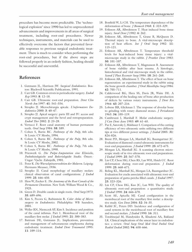
(Fig. 33). The radiographic appearance may also
improve with ‘ultrasonic densification’ (74) (Fig. 34).
Currently, however, there are no studies evaluating
which techniques are most efficacious for the place-
ment of MTA.
MTA has a 2–3 h working time (68), which is more
than adequate for apical microsurgery and takes the
‘time pressure’ out of the procedure. The surface of
the MTA is finished by carving away excess material to
the level of the resected root end. This is done in a dry
Fig. 31. The Lee mineral trioxide aggregate (MTA) pelletforming block greatly simplifies the process of deliveringMTA to the root-end preparation (REP). (A) The MTAmixed to a ‘putty-like’ consistency on a spatula is (B)placed onto the appropriate size groove in the Lee MTAblock, (C) pressed into the groove with a finger, (D) thesurface around the groove is wiped clean with a finger, (E)the desired length of the MTA is selected, (F) to beremoved by instrument, and (G) carried to the REP in anefficient manner. Slides courtesy Dr Arnaldo Castellucci,Florence, Italy.
Fig. 32. (A) Pre-measured aliquot of mineral trioxideaggregate (MTA) is easily delivered into the root-endpreparation. (B) A sufficient quantity of MTA can becarried on the instrument to minimize the number of‘passes’ needed to be made to the surgeon. (C) Because ofthe efficiency of the system, in many cases, two to threealiquots will suffice to overfill the REP with MTA slightly.
Fig. 33. (A) A plugger, or explorer tip, is placed just incontact with the mineral trioxide aggregate (MTA) and(B) while the doctor activates the ultrasonic hand piecewith a rheostat, the assistant gently touches the non-working end of the instrument with an activatedultrasonic tip to ‘ultrasonically densify’ the MTA.
Root-end management
147
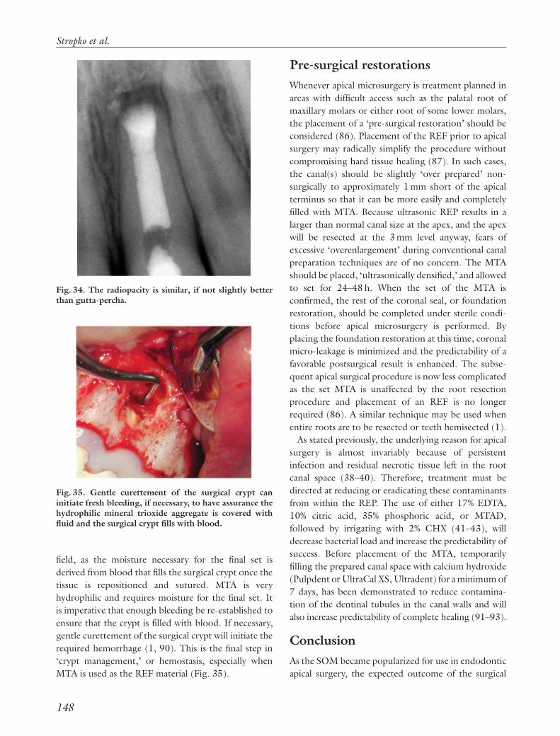
field, as the moisture necessary for the final set is
derived from blood that fills the surgical crypt once the
tissue is repositioned and sutured. MTA is very
hydrophilic and requires moisture for the final set. It
is imperative that enough bleeding be re-established to
ensure that the crypt is filled with blood. If necessary,
gentle curettement of the surgical crypt will initiate the
required hemorrhage (1, 90). This is the final step in
‘crypt management,’ or hemostasis, especially when
MTA is used as the REF material (Fig. 35).
Pre-surgical restorations
Whenever apical microsurgery is treatment planned in
areas with difficult access such as the palatal root of
maxillary molars or either root of some lower molars,
the placement of a ‘pre-surgical restoration’ should be
considered (86). Placement of the REF prior to apical
surgery may radically simplify the procedure without
compromising hard tissue healing (87). In such cases,
the canal(s) should be slightly ‘over prepared’ non-
surgically to approximately 1 mm short of the apical
terminus so that it can be more easily and completely
filled with MTA. Because ultrasonic REP results in a
larger than normal canal size at the apex, and the apex
will be resected at the 3 mm level anyway, fears of
excessive ‘overenlargement’ during conventional canal
preparation techniques are of no concern. The MTA
should be placed, ‘ultrasonically densified,’ and allowed
to set for 24–48 h. When the set of the MTA is
confirmed, the rest of the coronal seal, or foundation
restoration, should be completed under sterile condi-
tions before apical microsurgery is performed. By
placing the foundation restoration at this time, coronal
micro-leakage is minimized and the predictability of a
favorable postsurgical result is enhanced. The subse-
quent apical surgical procedure is now less complicated
as the set MTA is unaffected by the root resection
procedure and placement of an REF is no longer
required (86). A similar technique may be used when
entire roots are to be resected or teeth hemisected (1).
As stated previously, the underlying reason for apical
surgery is almost invariably because of persistent
infection and residual necrotic tissue left in the root
canal space (38–40). Therefore, treatment must be
directed at reducing or eradicating these contaminants
from within the REP. The use of either 17% EDTA,
10% citric acid, 35% phosphoric acid, or MTAD,
followed by irrigating with 2% CHX (41–43), will
decrease bacterial load and increase the predictability of
success. Before placement of the MTA, temporarily
filling the prepared canal space with calcium hydroxide
(Pulpdent or UltraCal XS, Ultradent) for a minimum of
7 days, has been demonstrated to reduce contamina-
tion of the dentinal tubules in the canal walls and will
also increase predictability of complete healing (91–93).
Conclusion
As the SOM became popularized for use in endodontic
apical surgery, the expected outcome of the surgical
Fig. 34. The radiopacity is similar, if not slightly betterthan gutta-percha.
Fig. 35. Gentle curettement of the surgical crypt caninitiate fresh bleeding, if necessary, to have assurance thehydrophilic mineral trioxide aggregate is covered withfluid and the surgical crypt fills with blood.
Stropko et al.
148
procedure has become more predictable. The ‘techno-
logical explosion’ since 1990 has led to unprecedented
advancements and improvements in all areas of surgical
treatment, including root-end procedures. Newer
techniques, instruments, and materials can be used to
effectively overcome the factors that prevented favor-
able responses to previous surgical endodontic treat-
ment. There is much to consider when performing the
root-end procedures, but if the above steps are
followed properly in an orderly fashion, healing should
be successful and uneventful.
References
1. Gutmann JL, Harrison JW. Surgical Endodontics. Bos-ton: Blackwell Scientific Publications, 1991.
2. Carr GB. Common errors in periradicular surgery. EndodRep 1993: 8: 12–18.
3. Carr GB. Ultrasonic root-end preparation. Dent ClinNorth Am 1997: 41: 541–554.
4. Stropko JJ. Microchirurgia apicale. L’informatore En-dodontico 2000: 3: 40–47.
5. Stropko JJ. Apical surgery: parts III and IV: access andcrypt management and the bevel and retropreparation.Endod Ther 2002: 2: 23–28.
6. Vertucci F. Root canal anatomy of human permanentteeth. Oral Surg 1984: 58: 589.
7. Cohen S, Burns RC. Pathways of the Pulp, 6th edn.St Louis: CV Mosby, 1994.
8. Cohen S, Burns RC. Pathways of the Pulp, 8th edn.St Louis: CV Mosby, 2002.
9. Cohen S, Burns RC. Pathways of the Pulp, 7th edn.St Louis: CV Mosby, 1998.
10. Prieswerk G. Die Pulpa-Amputation eine Klinische,Pathohistologische und Bakeriologishe Studie. Osterr.-Ungar: Vjschr. Zahnjeilk, 1901.
11. Peter K. Die Wurzelspitzenresektion der Molaren. Leipzig:Hermann Meusser, 1936.
12. Stropko JJ. Canal morphology of maxillary molars:clinical observation of canal configurations. J Endod1999: 25: 446–450.
13. Hess W, Zucker E. The Anatomy of the Root Canals of thePermanent Dentition. New York: William Wood & Co.,1925.
14. Green D. Double canals in single roots. Oral Surg 1973:35: 689–696.
15. Kim S, Pecora G, Rubinstein R. Color Atlas of Micro-surgery in Endodontics. Philadelphia: WB Saunders,2001.
16. Weller RN, Niemczyk SP, Kim S. Incidence and positionof the canal isthmus. Part 1. Mesiobuccal root of themaxillary first molar. J Endod 1995: 21: 380–383.
17. Battrum DE, Gutmann JL. Implications, preventionand management of subcutaneous emphysema duringendodontic treatment. Endod Dent Traumatol 1995:11: 109–114.
18. Bonfield W, Li CH. The temperature dependence of thedeformation of bone. J Biomech 1968: 1: 323–329.
19. Eriksson AR, Albrektsson T. Heat induced bone tissueinjury. Swed Dent J 1982: 6: 262.
20. Eriksson AR, Albrektsson T, Grane B, McQueen D.Thermal injury to bone. A vital-microscope descrip-tion of heat effects. Int J Oral Surg 1982: 11:115–121.
21. Eriksson AR, Albrektsson T. Temperature thresholdlevels for heat-induced bone tissue injury: a vital-microscope study in the rabbit. J Prosthet Dent 1983:50: 101–107.
22. Eriksson AR, Albrektsson T, Magnusson B. Assessmentof bone viability after heat trauma. A histologic,histochemical and vital microscope study in the rabbit.Scand J Plast Reconstr Surg 1984: 18: 261–268.
23. Eriksson AR, Albrektsson T. The effect of heat on boneregeneration: an experimental study in the rabbit usingthe bone growth chamber. J Oral Maxillofac Surg 1984:42: 705–711.
24. Calderwood RG, Hera SS, Davis JR, Waite DE. Acomparison of the healing rate of bone after productionof defects by various rotary instruments. J Dent Res1964: 43: 207–216.
25. Lobene RR, Glickman I. The response of alveolar boneto grinding with rotary diamond stones. J Periodontol1963: 34: 105–119.
26. Cambruzzi J, Marshall F. Molar endodontic surgery.J Can Dent Assoc 1983: 49: 61–65.
27. Paz E, Satovsky J, Maldauer I. Comparison of the cuttingefficiency of two ultrasonic units utilizing two differenttips at two different power settings. J Endod 2005: 31:824–826.
28. Brent PD, Morgan LA, Marshall JG, Baumgartner JC.Evaluation of diamond-coated ultrasonic instruments forroot-end preparations. J Endod 1999: 25: 672–675.
29. Morgan LA, Marshall JG. A scanning electron micro-scopic study of in vivo ultrasonic root-end preparations.J Endod 1999: 25: 567–570.
30. Lin CP, Chou HG, Chen RS, Lan WH, Hsieh CC. Rootdeformation during root-end preparation. J Endod1999: 25: 668–671.
31. Beling KL, Marshall JG, Morgan LA, Baumgardner JC.Evaluation for cracks associated with ultrasonic root-endpreparation of gutta-percha filled canals. J Endod 1997:23: 323–326.
32. Lin CP, Chou HG, Kuo JC, Lan WH. The quality ofultrasonic root-end preparation: a quantitative study.J Endod 1998: 24: 666–670.
33. Scott AE, Apicella MJ. Canal configuration in themesiobuccal root of the maxillary first molar: a descrip-tive study. Gen Dent 2004: 52: 34–35.
34. Kulild JC, Peters DD. Incidence and configuration ofcanal systems in the mesiobuccal root of maxillary firstand second molars. J Endod 1990: 16: 311.
35. Torabinejad M, Handysides R, Khademi AA, BaklandLK. Clinical implications of the smear layer in endodon-tics: a review. Oral Surg Oral Med Oral Pathol OralRadiol Endod 2002: 94: 658–666.
Root-end management
149

36. Torabinejad M, Khademi AA, Babagoli J, Cho Y,Johnson WB, Bozhilov K, Kim J, Shabahang S. A newsolution for the removal of the smear layer. J Endod2003: 29: 170–175.
37. Gogos C, Stavianos C, Kolokouris I, Papadoyannis I,Economides N. Shear bond strength of AH-26 rootcanal sealer to dentine using three dentine bondingagents. J Dent 2003: 31: 321–326.
38. Gutmann JL, Saunders WP, Nguyen L, Guo IY, SaundersEM. Ultrasonic root-end preparation. Part 1. SEManalysis. Int Endod J 1994: 27: 318–324.
39. Cheung GS. Endodontic failures – changing theapproach. Int Dent J 1996: 46: 131–138.
40. Hancock HH III, Sigurdsson A, Trope M, MoiseiwitschJ. Bacteria isolated after unsuccessful endodontic treat-ment in a North American population. Oral Surg OralMed Oral Pathol Oral Radiol Endod 2001: 91: 579–586.
41. Pinheiro ET, Gomes BP, Ferraz CC, Teixeira FB, ZaiaAA, Souza-Filho FJ. Evaluation of root canal micro-organisms isolated from teeth with endodontic failureand their antimicrobial susceptibility. Oral MicrobiolImmunol 2003: 18: 100–103.
42. Portenier I, Waltimo TMT, Haapasalo M. Enterococcusfaecalis- the root canal survivor and ‘star’ in post-treatment disease. Endodontic Topics 2003: 6: 135–159.
43. Engstrom B. The significance of enterococci in root canaltreatment. Odontol Revy 1964: 15: 87–106.
44. Molander A, Reit C, Dahlen G, Kvist T. Microbiologicalstatus of root-filled teeth with apical periodontitis. IntEndod J 1998: 31: 1–7.
45. Leonardo MR, Filho MT, Silva LAB, Filho PN,Bonifacio KC, Ito IY. In vivo antimicrobial activity of2% chlorhexidine used as a root canal irrigating solution.J Endod 1999: 25: 167–171.
46. Martin MV, Nind D. Use of chlorhexidine gluconate forpre-operative disinfection of apicectomy sites. Br Dent J1987: 162: 459–461.
47. Vianna ME, Gomes BP, Berber VB, Zaia AA, Ferraz CC,de Souza-Filho FJ. In vitro evaluation of the antimicro-bial activity of chlorhexidine and sodium hypochlorite.Oral Surg Oral Med Oral Pathol Oral Radiol Endod2004: 97: 79–84.
48. Gomes BP, Ferraz CC, Vianna ME, Berber VB, TeixeiraFB, Souza-Filho FJ. In vitro antimicrobial activity ofseveral concentrations of sodium hypochlorite andchlorhexidine gluconate in the elimination of Entero-coccus faecalis. Int Endod J 2001: 34: 424–428.
49. Bondar VM, Rago C, Cottone FJ, Wilkerson DK, Riggs J.Chlorhexidine lavage in the treatment of experimental intra-abdominal infection. Arch Surg 2000: 135: 309–314.
50. Basrani B, Lemonie C. Chlorhexidine gluconate. AusEndod J 2005: 31: 48–52.
51. Fogel HM, Peikoff MD. Microleakage of root-endmaterials. J Endod 2001: 27: 456–458.
52. Holt GM, Dumsha TC. Leakage of amalgam, composite,Super-EBA, compared with a new retrofill material: bonecement. J Endod 2000: 26: 29–31.
53. Scheerer SQ, Steiman HR, Cohen J. A comparativeevaluation of three root-end filling materials: an in vitro
leakage study using Prevotella nigrescens. J Endod 2001:27: 40–42.
54. Greer BD, West LA, Liewehr FR, Pashley DH. Sealingability of Dyract, Geristore, IRM and super-EBA as root-end filling materials. J Endod 2001: 27: 441–443.
55. Lindeboom JA, Frenken JW, Kroon FH, van den AkkerHP. A comparative prospective randomized clinical studyof MTA and IRM as root-end filling materials in single-rooted teeth in endodontic surgery. Oral Surg Oral MedOral Pathol Oral Radiol Endod 2005: 100: 495–500.
56. Fisher EJ, Arens DE, Miller CH. Bacterial leakage ofmineral trioxide aggregate as compared with zinc-freeamalgam, intermediate restorative material, and Super-EBA as a root-end filling material. J Endod 1998: 24:176–179.
57. Dorn SO, Gartner AH. Retrograde filling materials: aretrospective success-failure study of amalgam, EBA, andIRM. J Endod 1990: 16: 391–393.
58. Harrison JW, Johnson SA. Excisional wound healingfollowing the use of IRM as a root-end filling material.J Endod 1997: 23: 19–27.
59. Aqrabawi J. Sealing ability of amalgam, super EBAcement, and MTA when used as retrograde fillingmaterials. Br Dent J 2000: 188: 266–268.
60. Wu MK, Kontakiotis EG, Wesselink PR. Long-term sealprovided by some root-end filling materials. J Endod1998: 24: 557–560.
61. Zhu Q, Safavi KE, Spangberg LS. Cytotoxic evaluationof root-end filling materials in cultures of humanosteoblast-like cells and periodontal ligament cells.J Endod 1999: 25: 410–412.
62. Oynick J, Oynick T. A study of a new material forretrograde fillings. J Endod 1978: 4: 203–206.
63. Bondra DL, Hartwell GR, MacPhearson MG, PortellFR. Leakage in vitro with IRM, high copper, and EBAcement as retrofilling materials. J Endod 1989: 15: 157–160.
64. Saunders WP, Saunders EM, Gutmann JL. Ultrasonicroot-end preparation: Part II. Microleakage of EBAroot-end fillings. Int Endod J 1994: 27: 325–329.
65. Rubinstein RA, Kim S. Short-term observation of theresults of endodontic surgery with the use of a surgicaloperation microscope and super-EBA as root-end fillingmaterial. J Endod 1999: 25: 43–48.
66. Rubinstein RA, Kim S. Long-term follow-up of casesconsidered healed one year after apical microsurgery.J Endod 2001: 28: 378–383.
67. Ferracane JL. Materials in Dentistry. Philadelphia: JBLippincott, 1995.
68. Anusavice KJ. Philips’ Science of Dental Materials, 11thedn. St Louis: WB Saunders, 2003.
69. Coleman JM, Kirk EEJ. An assessment of a modifiedzinc oxide eugenol cement. Br Dent J 1965: 118: 482–487.
70. Henry J. Super EBA Instructions for Use. Bosworth,2005.
71. Gondim E, Zaia AA, Gomes BP, Ferraz CC, Teixeira FB,Souza-Filho FJ. Investigation of the marginal adapta-tion of root-end filling materials in root-end cavities
Stropko et al.
150

prepared with ultrasonic tips. Int Endod J 2003: 36:491–499.
72. Craig KR, Harrison JW. Wound healing followingdemineralization of resected root ends in periradicularsurgery. J Endod 1993: 19: 339–347.
73. Abedi HR, Torabinejad M, McMillan P. The effect ofdemineralization of resected root ends on cementogen-esis. J Endod 1997: 23: 258.
74. Jou Y, Pertl C. Is there a best retrograde filling material?Dent Clin North Am 1997: 3: 555–561.
75. Miles DA, Anderson RW, Pashley DH. Evaluation of thebond strength of dentin bonding agents used to sealresected root apices. J Endod 1994: 20: 538–541.
76. Jensen SS, Nattestad A, Egdo P, Sewerin I, MunksgaardEC, Schou S. A prospective, randomized, comparativeclinical study of resin composite and glass ionomercement for retrograde root filling. Clin Oral Invest 2002:6: 236–243.
77. Rud J, Rud V, Munksgaard EC. Long-term evaluation ofretrograde root filling with dentin-bonded resin compo-site. J Endod 1996: 22: 90–93.
78. Rud J, Munksgaard EC, Andreasen JO, Rud V,Asmussen E. Retrograde root filling with compositeand a dentin-bonding agent. 1. Endod Dent Traumatol1991: 7: 118–125.
79. Rud J, Munksgaard EC, Andreasen JO, Rud V. Retro-grade root filling with composite and a dentin-bondingagent. 2. Endod Dent Traumatol 1991: 7: 126–131.
80. Gutmann JL, Pitt Ford TR. Management of the resectedroot end: a clinical review. Int Endod J 1993: 26: 273–283.
81. Sherer W, Dragoo MR. New subgingival restorativeprocedures with Gerestore resin ionomer. Pract ProcedAesthet Dent 1995: 7: 1–4.
82. Michell PJ, Pitt Ford TR, Torabinejad M, McDonald F.Osteoblast biocompatibility of mineral trioxide aggre-gate. Biomaterials 1999: 20: 167–173.
83. Torabinejad M, Chivian N. Clinical applications ofmineral trioxide aggregate. J Endod 1999: 25: 197–203.
84. Koh ET, McDonald F, Pitt Ford TR, Torabinejad M.Cellular response to mineral trioxide aggregate. J Endod1998: 24: 543–547.
85. Osorio RM, Hefti A, Vertucci FJ, Shawley AL. Cytoto-xicity of endodontic materials. J Endod 1998: 24: 91–96.
86. Andelin WE, Browning DF, Hsu GR, Roland DD,Torabinejad T. Microleakage of resected MTA. J Endod2002: 28: 573–574.
87. Apaydin ES, Shabahang S, Torabinejad M. Hard-tissuehealing after application of fresh or set MTA as root-endfilling material. J Endod 2004: 30: 21–24.
88. Lee ES. A new mineral trioxide aggregate root-end fillingtechnique. J Endod 2000: 26: 764–766.
89. Lee ES. Think outside the syringe. Endod Pract 2004: 3:26–28.
90. Stropko JJ. Apical surgery: Parts V and VI: Retrofillmaterials, techniques, sutures and suturing techniques.Endod Ther 2003: 3: 10–15.
91. Bystrom A, Claesson R, Sundqvist G. The antibacterialeffect of camphorated paramonochlorophenol, campho-rated phenol and calcium hydroxide in the treatment ofinfected root canals. Endod Dent Traumatol 1985: 1:170–175.
92. Sjogren U, Figdor D, Spangberg L, Sundqvist G. Theantimicrobial effect of calcium hydroxide as a short-termintracanal dressing. Int Endod J 1991: 24: 119–125.
93. Law A, Messer H. An evidence-based analysis of theantibacterial effectiveness of intracanal medicaments.J Endod 2004: 30: 689–694.
Root-end management
151