Roof Insulations - Insulation, Roofing Systems & … Insulations Insulation should not be left...
16
Roof Insulations 1.0 Product Information Effective roof insulation helps lower overall energy consumption, reduces HVAC equipment requirements, and brings about improved comfort for the occupants of a building. JM provides these benefits with a full line of high performance insulations and cover for single ply, built-up, metal and modified bitumen roofs. The section that follows reviews the storage, installation and use instructions for the cover board and insulation board product lines. JM product line. Prior to product selection, it is recommended that the product performance, design and installation concepts of the roofing system be considered to ensure the correct product selection. The Fesco product line incorporates recycled cellulose and has been third-party certified for recycled content by UL ® Environment. With an average recycled content of 27% to 40%, this product line can provide LEED ® points (certified products) in certain jobs. The JM polyisocyanurate product line has product comprised of a closed-cell polyisocyanurate foam core bonded in the manufacturing process to various facers (glass- reinforced, paper, coated glass and aluminum foil). Finally, the Invinsa ® product line includes high-density polyisocyanurate cover boards that are lightweight with high compressive strength. These boards provide improved hail resistance and foot traffic resistance. 2.0 Guarantees It is also important to protect a roofing system with a guarantee of performance. JM offers a wide variety of Peak Advantage Guarantees, including many 20-year No-Dollar-Limit (NDL) specifications which are available from NDL Approved Contractors only. Check with a JM Technical Services Specialist for the names of approved NDL Contractors in your area and details on NDL guarantees including extended term guarantees. 3.0 Product Considerations 3.1 Insulation Characteristics. Roof insulation performs two basic functions in any roof system. It is the primary thermal barrier for the top surface of the building envelope, and it serves as a base for the roofing system. In order to perform these two functions successfully, any roof insulation should have the following characteristics: ■ ■ Sufficient thermal resistance (“R” Value) to meet the designer’s needs. ■ ■ Resistance to indentation, compression and crushing during installation of the roof membrane and during periodic maintenance, once the roof is completed. Cover boards are always recommended by JM. ■ ■ Rigidity to support the roof membrane and to span the rib openings of metal roof decks. ■ ■ Resistance to moisture absorption. ■ ■ Dimensional stability. ■ ■ Compatibility with common roofing systems and attachment techniques. ■ ■ Resistance to wind uplift, and pull-through of mechanical fasteners. ■ ■ Acceptability by Underwriters Laboratories ® Inc., FM Global ® and code agencies. 4.0 Design Considerations 4.1 Drainage. Proper drainage must be provided on all roof systems. Standing or ponded water hastens the deterioration of any roof system since the water can work its way through laps or any minor application flaw in the membrane. 4.2 Double Insulation Layers. Installing roof insulation in multiple layers provides the designer with improved thermal performance. It also contributes to the overall performance of the roof system for the following reasons: ■ ■ Recent studies indicate that as much as 8% of the thermal efficiency of the insulation can be lost through the insulation joints and exposed insulation fasteners of single layer installations. Insulation joints that are staggered in multiple layer installations block the flow of heat. ■ ■ Multiple layer insulation installation reduces the stress accumulation of a thick, single insulation joint and distributes the stress more evenly over the multiple, thinner insulation joints. ■ ■ The bottom side of the membrane is protected from physical damage from insulation plates and fasteners by the second layer of insulation. ■ ■ Roof decks are stiffened. 5.0 Insulation Installation Considerations 5.1 Protection from Weather. JM Roof Insulations (polyiso, Invinsa, and Fesco) are shipped with plastic shrouds that are intended to temporarily protect the insulation while in transit. Polyiso packaging from some JM plants is considered tarpless; meaning it can be shipped without covering the load with a tarpaulin. JM plants without tarpless packaging ship polyiso with loads covered by a tarpaulin. Please contact your technical representative to learn which JM factories use tarpless packaging. All JM insulation products (no matter how shipped), that are stored outdoors, must be stored in accordance with Johns Manville, NRCA (National Roofing Contractors Association) and PIMA (Polyisocyanurate Insulation Manufacturing Association) best roofing practices using a weatherproof covering such as a tarpaulin. In humid climates, JM recommends slitting the plastic shrink wrap (or removing the packaging all together), prior to covering the pallet with a breathable tarpaulin, to allow for venting. Furthermore, JM insulation should not be stored in or around standing water. JM recommends 3" to 4" of dunnage below individual pallets of insulation to keep it off the ground. RS-7386web 2-13 (Replaces 12-12)
Transcript of Roof Insulations - Insulation, Roofing Systems & … Insulations Insulation should not be left...
Roof Insulations
1.0 Product InformationEffective roof insulation helps lower overall energy consumption, reduces HVAC equipment requirements, and brings about improved comfort for the occupants of a building.
JM provides these benefits with a full line of high performance insulations and cover for single ply, built-up, metal and modified bitumen roofs. The section that follows reviews the storage, installation and use instructions for the cover board and insulation board product lines. JM product line. Prior to product selection, it is recommended that the product performance, design and installation concepts of the roofing system be considered to ensure the correct product selection.
The Fesco product line incorporates recycled cellulose and has been third-party certified for recycled content by UL® Environment. With an average recycled content of 27% to 40%, this product line can provide LEED® points (certified products) in certain jobs. The JM polyisocyanurate product line has product comprised of a closed-cell polyisocyanurate foam core bonded in the manufacturing process to various facers (glass-reinforced, paper, coated glass and aluminum foil). Finally, the Invinsa® product line includes high-density polyisocyanurate cover boards that are lightweight with high compressive strength. These boards provide improved hail resistance and foot traffic resistance.
2.0 GuaranteesIt is also important to protect a roofing system with a guarantee of performance. JM offers a wide variety of Peak Advantage Guarantees, including many 20-year No-Dollar-Limit (NDL) specifications which are available from NDL Approved Contractors only. Check with a JM Technical Services Specialist for the names of approved NDL Contractors in your area and details on NDL guarantees including extended term guarantees.
3.0 Product Considerations3.1 Insulation Characteristics. Roof insulation performs two basic functions in any roof system. It is the primary thermal barrier for the top surface of the building envelope, and it serves as a base for the roofing system. In order to perform these two functions successfully, any roof insulation should have the following characteristics:
■■ Sufficient thermal resistance (“R” Value) to meet the designer’s needs.
■■ Resistance to indentation, compression and crushing during installation of the roof membrane and during periodic maintenance, once the roof is completed. Cover boards are always recommended by JM.
■■ Rigidity to support the roof membrane and to span the rib openings of metal roof decks.
■■ Resistance to moisture absorption.■■ Dimensional stability.
■■ Compatibility with common roofing systems and attachment techniques.
■■ Resistance to wind uplift, and pull-through of mechanical fasteners.
■■ Acceptability by Underwriters Laboratories® Inc., FM Global® and code agencies.
4.0 Design Considerations4.1 Drainage. Proper drainage must be provided on all roof systems. Standing or ponded water hastens the deterioration of any roof system since the water can work its way through laps or any minor application flaw in the membrane.
4.2 Double Insulation Layers. Installing roof insulation in multiple layers provides the designer with improved thermal performance. It also contributes to the overall performance of the roof system for the following reasons:
■■ Recent studies indicate that as much as 8% of the thermal efficiency of the insulation can be lost through the insulation joints and exposed insulation fasteners of single layer installations. Insulation joints that are staggered in multiple layer installations block the flow of heat.
■■ Multiple layer insulation installation reduces the stress accumulation of a thick, single insulation joint and distributes the stress more evenly over the multiple, thinner insulation joints.
■■ The bottom side of the membrane is protected from physical damage from insulation plates and fasteners by the second layer of insulation.
■■ Roof decks are stiffened.
5.0 Insulation Installation Considerations5.1 Protection from Weather. JM Roof Insulations (polyiso, Invinsa, and Fesco) are shipped with plastic shrouds that are intended to temporarily protect the insulation while in transit. Polyiso packaging from some JM plants is considered tarpless; meaning it can be shipped without covering the load with a tarpaulin. JM plants without tarpless packaging ship polyiso with loads covered by a tarpaulin. Please contact your technical representative to learn which JM factories use tarpless packaging.
All JM insulation products (no matter how shipped), that are stored outdoors, must be stored in accordance with Johns Manville, NRCA (National Roofing Contractors Association) and PIMA (Polyisocyanurate Insulation Manufacturing Association) best roofing practices using a weatherproof covering such as a tarpaulin. In humid climates, JM recommends slitting the plastic shrink wrap (or removing the packaging all together), prior to covering the pallet with a breathable tarpaulin, to allow for venting. Furthermore, JM insulation should not be stored in or around standing water. JM recommends 3" to 4" of dunnage below individual pallets of insulation to keep it off the ground.
RS-7386web 2-13 (Replaces 12-12)
Roof Insulations
Insulation should not be left exposed to weather. No more insulation should be installed than can be completely covered with membrane on the same day. Factory packaging should not be relied upon as protection from the weather.
5.2 Asphalt Temperatures. JM endorses the guidelines established by the NRCA and ARMA for heating asphalt for proper insulation applications. Asphalt should be applied at the Equiviscous Temperature (EVT), ± 25°F (±14°C).
5.3 Cold Weather Application. Hot asphalt chills rapidly at 40°F (4°C). To avoid problems associated with “cold” asphalt application, insulation should be applied with mechanical fasteners or the “mop and flop” method of installing insulation. The “mop and flop” method entails mopping the back of the insulation so that the asphalt retains its adhesive qualities for a longer period. When applying insulation with hot asphalt, board size should not exceed 4' x 4' (1.22 m x 1.22 m). Care should be taken in any application below 40°F (4°C).
5.4 Mechanical Application to Steel Decks. Mechanical attachment of insulation to steel decks is the only acceptable attachment method. For current information regarding Factory Mutual requirements over insulated steel decks, please check with a JM Technical Services Specialist, or the current FM ApprovalsSM RoofNav.
5.5 Cold Adhesive Application. JM insulations may be installed in Insulation Adhesives:
■■ MBR Bonding Adhesive■■ One-Step Foamable Adhesive■■ Roofing Systems Urethane Adhesive
5.6 Foam Insulation Products are Combustible. They should be properly protected from exposure to fire during storage, transit and application.
5.7 Limitations. When installed over metal decks, spans shall be limited for specific deck gauges as outlined in the current FM Global® Loss Prevention Data Sheets 1-28, 1-29 and FM ApprovalsSM RoofNav. JM insulations are not recommended for applications where temperatures are outside the service temperatures of -100°F to 250°F (-73°C to 121°C). Although JM roof insulations are designed to be compatible with most membranes, the membrane manufacturer should be consulted for specific approval with individual membrane products.
6.0 Foam Thermal Values6.1 Thermal Values. The thermal values of all closed cell urethane or isocyanurate foam insulations are at their optimum at the time of manufacture. As these products “age,” some thermal loss occurs due to air infiltrating the foam cells and diluting the insulating gas in the cells. This process continues to occur over time. The degree to which this occurs is a function of the product formula and quality. It may vary from one manufacturer to another. The ultimate R-value of foam products will also depend on individual installation circumstances.
6.2 Long Term Thermal Resistance (LTTR). Johns Manville manufactures polyisocyanurate foam insulation products and reports R-Value in accordance with ASTM C 1289-12 and CAN/ULC S704. LTTR is a test procedure for a foam insulation with blowing agents other than air, giving a Thermal Resistance value in a 15 year time-weighted average. This method provides a more accurate method to report long term thermal performance for foam plastic insulation materials.
7.0 Definition of Terms and Symbols7.1 k-Value (Thermal Conductivity): the measurement of heat flow in BTUs through a 1" (25 mm) thickness of any single homogeneous material, per hour per sq. ft. per degree F temperature difference (W/m • °C).
7.2 C-Value (Thermal Conductance): the measurement of heat flow in BTUs per hour per sq. ft. per degree F temperature difference through any single material, regardless of thickness (W/m2 • °C).
7.3 R-Value (Thermal Resistance): the measurement of the resistance to heat flow. The reciprocal of the C-value.
7.4 U-Value (Overall Heat Transfer Coefficient): the measurement, in BTUs of heat flow, per hour per sq. ft. per degree F temperature difference through a combination of materials such as roof deck, vapor barrier, roof insulation, built-up roofing, and the air films below and above such combinations.
RS-7386web 2-13 (Replaces 12-12)
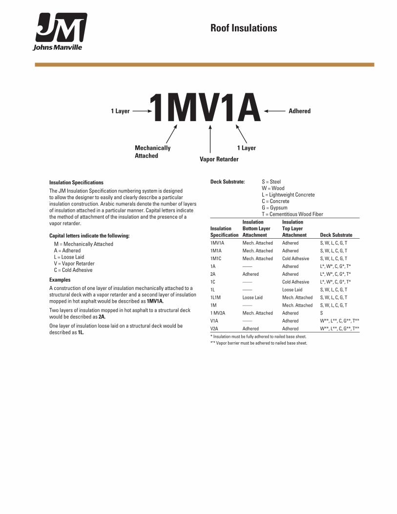
1MV1AMechanically Attached
1 Layer
1 Layer Adhered
Vapor Retarder
Deck Substrate: S = Steel W = Wood L = Lightweight Concrete C = Concrete G = Gypsum T = Cementitious Wood Fiber Insulation InsulationInsulation Bottom Layer Top LayerSpecification Attachment Attachment Deck Substrate1MV1A Mech. Attached Adhered S, W, L, C, G, T
1M1A Mech. Attached Adhered S, W, L, C, G, T
1M1C Mech. Attached Cold Adhesive S, W, L, C, G, T
1A —— Adhered L*, W*, C, G*, T*
2A Adhered Adhered L*, W*, C, G*, T*
1C —— Cold Adhesive L*, W*, C, G*, T*
1L —— Loose Laid S, W, L, C, G, T
1L1M Loose Laid Mech. Attached S, W, L, C, G, T
1M —— Mech. Attached S, W, L, C, G, T
1 MV2A Mech. Attached Adhered S
V1A —— Adhered W**, L**, C, G**, T**
V2A Adhered Adhered W**, L**, C, G**, T**
* Insulation must be fully adhered to nailed base sheet.*’* Vapor barrier must be adhered to nailed base sheet.
Insulation SpecificationsThe JM Insulation Specification numbering system is designed to allow the designer to easily and clearly describe a particular insulation construction. Arabic numerals denote the number of layers of insulation attached in a particular manner. Capital letters indicate the method of attachment of the insulation and the presence of a vapor retarder.
Capital letters indicate the following:M = Mechanically AttachedA = AdheredL = Loose LaidV = Vapor RetarderC = Cold Adhesive
ExamplesA construction of one layer of insulation mechanically attached to a structural deck with a vapor retarder and a second layer of insulation mopped in hot asphalt would be described as 1MV1A.
Two layers of insulation mopped in hot asphalt to a structural deck would be described as 2A.
One layer of insulation loose laid on a structural deck would be described as 1L.
Roof Insulations
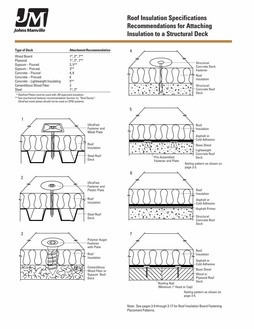
Roof Insulation Specifications Recommendations for Attaching Insulation to a Structural Deck
Type of Deck Attachment Recommendation
Wood Board 1*, 2*, 7**Plywood 1*, 2*, 7**Gypsum – Poured 3, 5**Gypsum – Precast 3**Concrete – Poured 4, 6Concrete – Precast 6Concrete – Lightweight Insulating 5**Cementitious Wood Fiber 3Steel 1*, 2* * GlasFast Plates must be used with JM approved insulation.** See mechanical fastener recommendation Section 1e, “Roof Decks”.
UltraFast metal plates should not be used on SPM systems.
.
.
.
.
..
.
..
.
. ..
..
.
. ..
...
.
.. .
Structural Concrete Deck Fastener
Roof Insulation
Structural Concrete Roof Deck
4
.
.
.
.
..
.
..
.
. ..
..
.
. ..
...
.
.. . Structural Concrete Roof Deck
Roof Insulation
Asphalt or Cold Adhesive
Asphalt Primer
6
Roof Insulation
Asphalt or Cold Adhesive
Wood or Plywood Roof Deck
Base Sheet
Roofing Nail (Minimum 1" Head or Cap)
7
UltraFastFastener and Metal Plate
Roof Insulation
Steel Roof Deck
1
UltraFastFastener and Plastic Plate
Roof Insulation
Steel Roof Deck
2
Polymer Auger Fastener with Plate
Roof Insulation
Cementitious Wood Fiber or Gypsum Roof Deck
3
.
.
.
.
..
.
..
.
. ..
..
.
. ..
...
.
.. .
Asphalt or Cold Adhesive
Roof Insulation
Lightweight Concrete Roof Deck
Base Sheet
Pre-Assembled Fastener and Plate
5
Nailing pattern as shown on page 3-5.
Nailing pattern as shown on page 3-5.
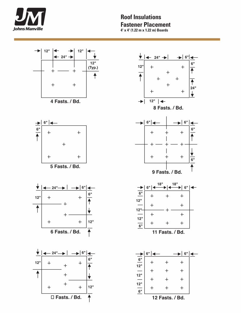
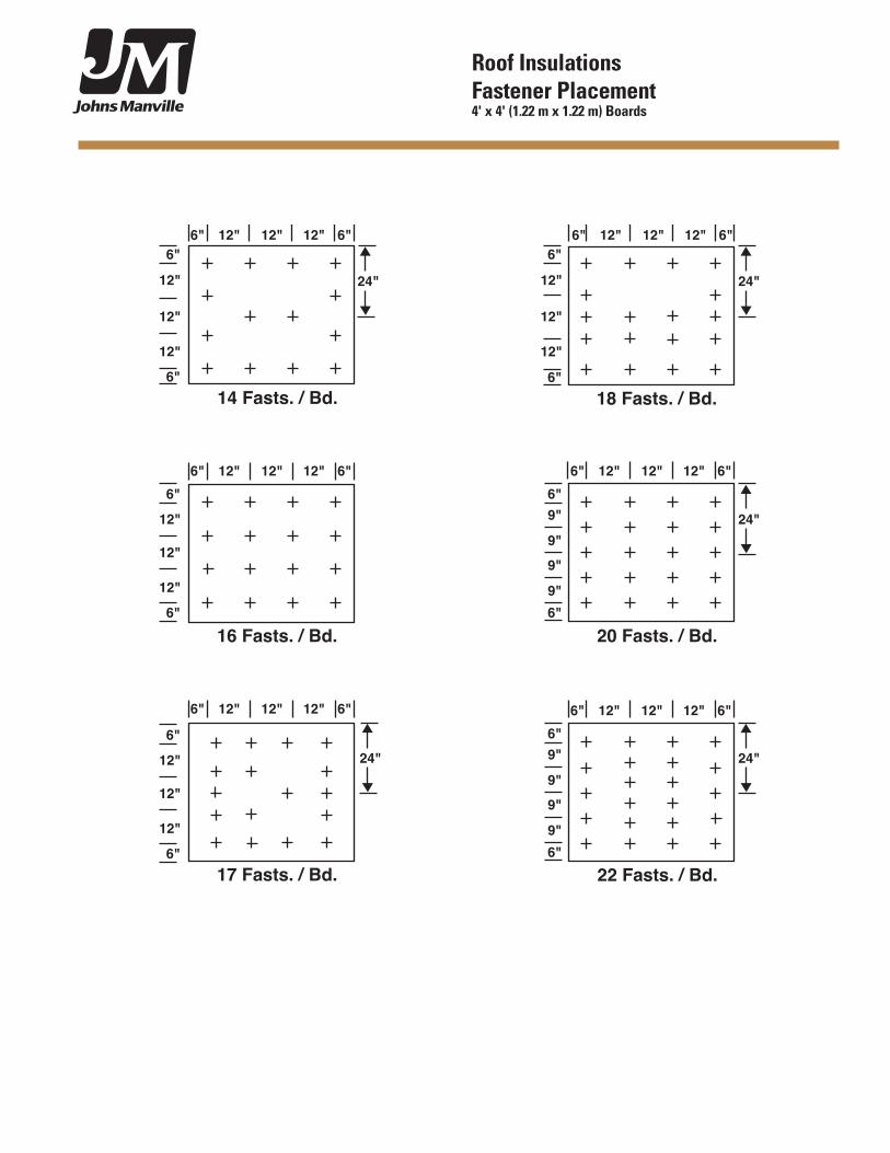
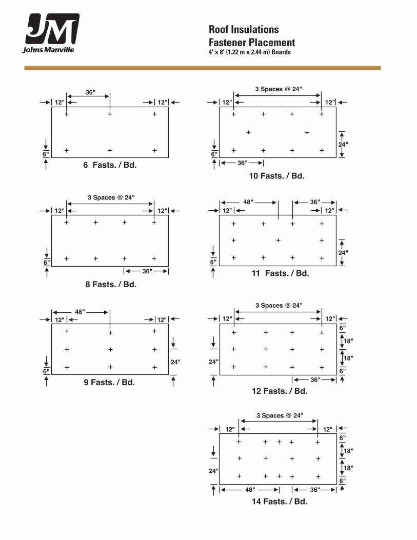
Note: See pages 3-9 through 3-17 for Roof Insulation Board Fastening Placement Patterns.
Roof Insulation Specifications Specification 1A Specification 1L One Layer Asphalt Attached One Layer Loose Laid
Specification 1C One Layer Cold Adhesive Attached
Specification 1C
.
.
.
.
..
.
..
.
. ..
..
.
. ..
...
.
.. . .
...
..
. .
...
..
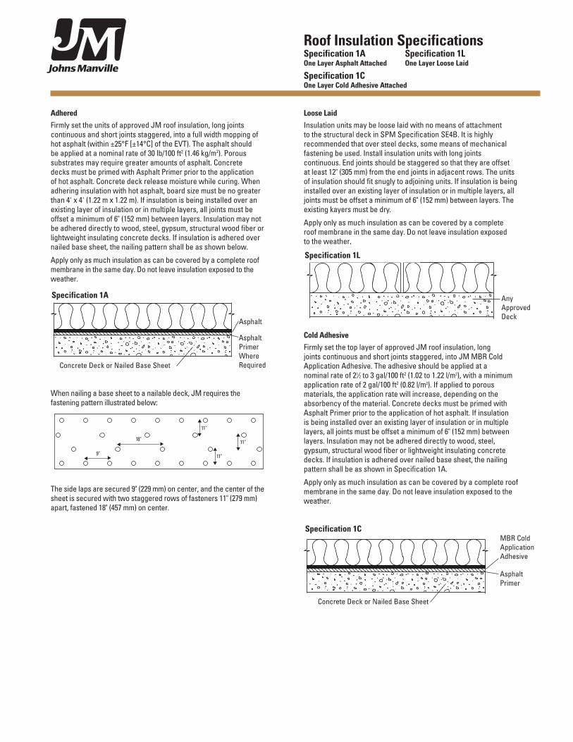
Asphalt Primer
MBR Cold Application Adhesive
Concrete Deck or Nailed Base Sheet
Adhered Firmly set the units of approved JM roof insulation, long joints continuous and short joints staggered, into a full width mopping of hot asphalt (within ±25°F [±14°C] of the EVT). The asphalt should be applied at a nominal rate of 30 lb/100 ft2 (1.46 kg/m2). Porous substrates may require greater amounts of asphalt. Concrete decks must be primed with Asphalt Primer prior to the application of hot asphalt. Concrete deck release moisture while curing. When adhering insulation with hot asphalt, board size must be no greater than 4' x 4' (1.22 m x 1.22 m). If insulation is being installed over an existing layer of insulation or in multiple layers, all joints must be offset a minimum of 6" (152 mm) between layers. Insulation may not be adhered directly to wood, steel, gypsum, structural wood fiber or lightweight insulating concrete decks. If insulation is adhered over nailed base sheet, the nailing pattern shall be as shown below.
Apply only as much insulation as can be covered by a complete roof membrane in the same day. Do not leave insulation exposed to the weather.
When nailing a base sheet to a nailable deck, JM requires the fastening pattern illustrated below:
The side laps are secured 9" (229 mm) on center, and the center of the sheet is secured with two staggered rows of fasteners 11" (279 mm) apart, fastened 18" (457 mm) on center.
Loose LaidInsulation units may be loose laid with no means of attachment to the structural deck in SPM Specification SE4B. It is highly recommended that over steel decks, some means of mechanical fastening be used. Install insulation units with long joints continuous. End joints should be staggered so that they are offset at least 12" (305 mm) from the end joints in adjacent rows. The units of insulation should fit snugly to adjoining units. If insulation is being installed over an existing layer of insulation or in multiple layers, all joints must be offset a minimum of 6" (152 mm) between layers. The existing kayers must be dry.
Apply only as much insulation as can be covered by a complete roof membrane in the same day. Do not leave insulation exposed to the weather.
Cold AdhesiveFirmly set the top layer of approved JM roof insulation, long joints continuous and short joints staggered, into JM MBR Cold Application Adhesive. The adhesive should be applied at a nominal rate of 21⁄2 to 3 gal/100 ft2 (1.02 to 1.22 l/m2), with a minimum application rate of 2 gal/100 ft2 (0.82 l/m2). If applied to porous materials, the application rate will increase, depending on the absorbency of the material. Concrete decks must be primed with Asphalt Primer prior to the application of hot asphalt. If insulation is being installed over an existing layer of insulation or in multiple layers, all joints must be offset a minimum of 6" (152 mm) between layers. Insulation may not be adhered directly to wood, steel, gypsum, structural wood fiber or lightweight insulating concrete decks. If insulation is adhered over nailed base sheet, the nailing pattern shall be as shown in Specification 1A.
Apply only as much insulation as can be covered by a complete roof membrane in the same day. Do not leave insulation exposed to the weather.
.
.
.
.
..
.
..
.
. ..
..
.
. ..
...
.
.. . .
...
..
. .
...
..
Any Approved Deck
Specification 1L
t
t
t
t
t
t
t
t
t
t
11"
11"
18"
9"
11"
Specification 1A
.
.
.
.
..
.
..
.
. ..
..
.
. ..
...
.
.. . .
...
..
. .
...
..
Asphalt Primer Where Required
Asphalt
Concrete Deck or Nailed Base Sheet
Roof Insulation Specifications Specification 1M One Layer Mechanically Attached
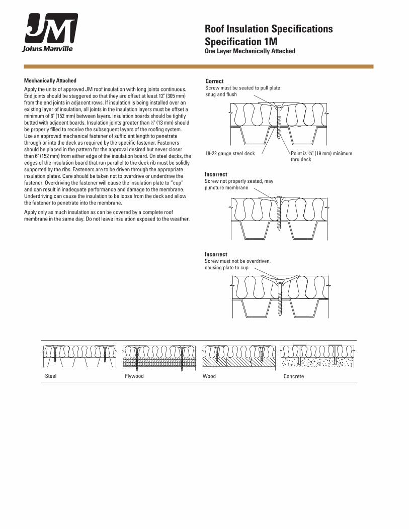
Mechanically Attached Apply the units of approved JM roof insulation with long joints continuous. End joints should be staggered so that they are offset at least 12" (305 mm) from the end joints in adjacent rows. If insulation is being installed over an existing layer of insulation, all joints in the insulation layers must be offset a minimum of 6" (152 mm) between layers. Insulation boards should be tightly butted with adjacent boards. Insulation joints greater than 1⁄2" (13 mm) should be properly filled to receive the subsequent layers of the roofing system. Use an approved mechanical fastener of sufficient length to penetrate through or into the deck as required by the specific fastener. Fasteners should be placed in the pattern for the approval desired but never closer than 6" (152 mm) from either edge of the insulation board. On steel decks, the edges of the insulation board that run parallel to the deck rib must be solidly supported by the ribs. Fasteners are to be driven through the appropriate insulation plates. Care should be taken not to overdrive or underdrive the fastener. Overdriving the fastener will cause the insulation plate to “cup” and can result in inadequate performance and damage to the membrane. Underdriving can cause the insulation to be loose from the deck and allow the fastener to penetrate into the membrane.
Apply only as much insulation as can be covered by a complete roof membrane in the same day. Do not leave insulation exposed to the weather.
Steel Plywood Wood
.
.
.
.
..
.
..
.
. ..
..
.
. ..
...
.
.. . .
...
..
. .
...
..
Concrete
CorrectScrew must be seated to pull plate snug and flush
18-22 gauge steel deck Point is 3⁄4" (19 mm) minimum thru deck
IncorrectScrew not properly seated, may puncture membrane
IncorrectScrew must not be overdriven, causing plate to cup
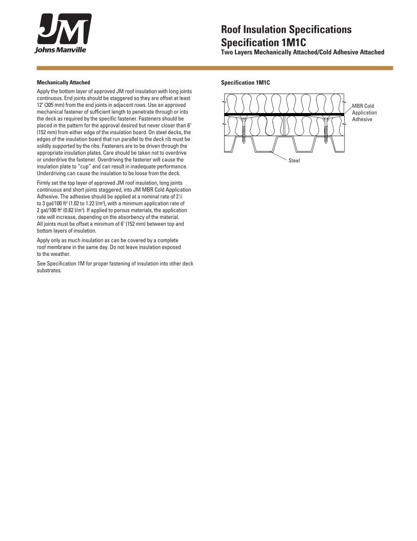
Roof Insulation Specifications Specification 1M1C Two Layers Mechanically Attached/Cold Adhesive Attached
Mechanically AttachedApply the bottom layer of approved JM roof insulation with long joints continuous. End joints should be staggered so they are offset at least 12" (305 mm) from the end joints in adjacent rows. Use an approved mechanical fastener of sufficient length to penetrate through or into the deck as required by the specific fastener. Fasteners should be placed in the pattern for the approval desired but never closer than 6" (152 mm) from either edge of the insulation board. On steel decks, the edges of the insulation board that run parallel to the deck rib must be solidly supported by the ribs. Fasteners are to be driven through the appropriate insulation plates. Care should be taken not to overdrive or underdrive the fastener. Overdriving the fastener will cause the insulation plate to “cup” and can result in inadequate performance. Underdriving can cause the insulation to be loose from the deck.
Firmly set the top layer of approved JM roof insulation, long joints continuous and short joints staggered, into JM MBR Cold Application Adhesive. The adhesive should be applied at a nominal rate of 2 1⁄2 to 3 gal/100 ft2 (1.02 to 1.22 l/m2), with a minimum application rate of 2 gal/100 ft2 (0.82 l/m2). If applied to porous materials, the application rate will increase, depending on the absorbency of the material. All joints must be offset a minimum of 6" (152 mm) between top and bottom layers of insulation.
Apply only as much insulation as can be covered by a complete roof membrane in the same day. Do not leave insulation exposed to the weather.
See Specification 1M for proper fastening of insulation into other deck substrates.
MBR Cold Application Adhesive
Specification 1M1C
Steel
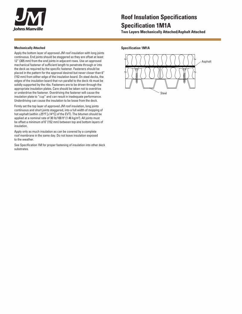
Mechanically AttachedApply the bottom layer of approved JM roof insulation with long joints continuous. End joints should be staggered so they are offset at least 12” (305 mm) from the end joints in adjacent rows. Use an approved mechanical fastener of sufficient length to penetrate through or into the deck as required by the specific fastener. Fasteners should be placed in the pattern for the approval desired but never closer than 6” (152 mm) from either edge of the insulation board. On steel decks, the edges of the insulation board that run parallel to the deck rib must be solidly supported by the ribs. Fasteners are to be driven through the appropriate insulation plates. Care should be taken not to overdrive or underdrive the fastener. Overdriving the fastener will cause the insulation plate to “cup” and can result in inadequate performance. Underdriving can cause the insulation to be loose from the deck.
Firmly set the top layer of approved JM roof insulation, long joints continuous and short joints staggered, into a full width of mopping of hot asphalt (within ±25°F [±14°C] of the EVT). The bitumen should be applied at a nominal rate of 30 Ib/100 ft2 (1.46 kg/m2). All joints must be offset a minimum of 6" (152 mm) between top and bottom layers of insulation.
Apply only as much insulation as can be covered by a complete roof membrane in the same day. Do not leave insulation exposed to the weather.
See Specification 1M for proper fastening of insulation into other deck substrates.
Asphalt
Specification 1M1A
Steel
Roof Insulation SpecificationsSpecification 1M1A Two Layers Mechanically Attached/Asphalt Attached
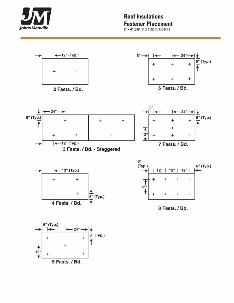
Roof Insulations Fastener Placement 2' x 4' (0.61 m x 1.22 m) Boards
5 Fasts. / Bd.
6" (Typ.)
6" (Typ.)
6 Fasts. / Bd.
6"6" (Typ.)
24"
4 Fasts. / Bd.
12" (Typ.)
6" (Typ.)
7 Fasts. / Bd.
6"
6" (Typ.)24"
2 Fasts. / Bd.
12" (Typ.)
6" (Typ.)6" (Typ.)
12"
12"12"12"
8 Fasts. / Bd.
12"
12"
24"
24"
3 Fasts. / Bd. - Staggered
6" (Typ.)
12" (Typ.)
6 Fasts. / Bd.
24"
12 Fasts. / Bd.
9 Fasts. / Bd.
6"
6" 6"
6"
6" 6"6"
6"
6"6"
12"12"
12"
12"
6"6" 6"
6"
12"
12"
12"
12"
24"6"
6"
12"
12"
14 Fasts. / Bd.
6 in.12 in.
12 in.
12 in.6 in.
24 in
.
6 in. 12 in. 12 in. 12 in. 6 in.
5 Fasts. / Bd.
6"
6"
4 Fasts. / Bd.
12"(Typ.)
24"12"12"
11 Fasts. / Bd.
18" 18"
� Fasts. / Bd.
8 Fasts. / Bd.
6"12"
12"
6"24"
24"
Roof Insulations Fastener Placement 4' x 4' (1.22 m x 1.22 m) Boards
14 Fasts. / Bd.
6"6" 6"
6"
12"
12" 12" 12"
24"
12"
12"
6"6" 6"
6"
6"
6"
12"
12" 12" 12" 6" 6"12" 12" 12"
6" 6"12" 12" 12"
12"
12"
6"6" 6"
6"
12"
12" 12" 12"
12"
12"
24"
24"
24"24"
16 Fasts. / Bd.
9"
9"
9"
9"
6"
6"
9"
9"
9"
9"
6"
6" 6"
6"
12"
12" 12" 12"
12"
12"
17 Fasts. / Bd.
18 Fasts. / Bd.
20 Fasts. / Bd.
22 Fasts. / Bd.
Roof Insulations Fastener Placement 4' x 4' (1.22 m x 1.22 m) Boards
6 Fasts. / Bd.
36"
8 Fasts. / Bd.
6"
12"
6"
12"
10 Fasts. / Bd.
3 Spaces @ 24"
6"
12"
6"
12"
3 Spaces @ 24"
12" 12"
3 Spaces @ 24"
12" 12"
6"
6"
6"12"12"
9 Fasts. / Bd.
11 Fasts. / Bd.
48"
48"
36"48"
36"
36"
36"
36"
24"
24"
24"
24"
24"
12"12"
12 Fasts. / Bd.
18"
18"
6"
6"12"12"
18"
18"
14 Fasts. / Bd.
3 Spaces @ 24"
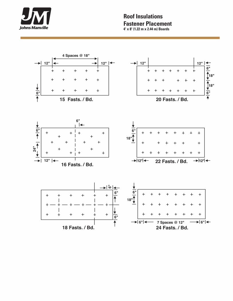
Roof Insulations Fastener Placement 4' x 8' (1.22 m x 2.44 m) Boards
6"
18"
6"
12"16 Fasts. / Bd.
6"
24"
6"
12"
15 Fasts. / Bd.
12"
4 Spaces @ 18"
6"
18"
22 Fasts. / Bd. 12"12"
18 Fasts. / Bd.
6"
6"
6"
6"
12"
20 Fasts. / Bd.
12"6"
18"
18"
6" 7 Spaces @ 12"24 Fasts. / Bd.
6"
Roof Insulations Fastener Placement 4' x 8' (1.22 m x 2.44 m) Boards
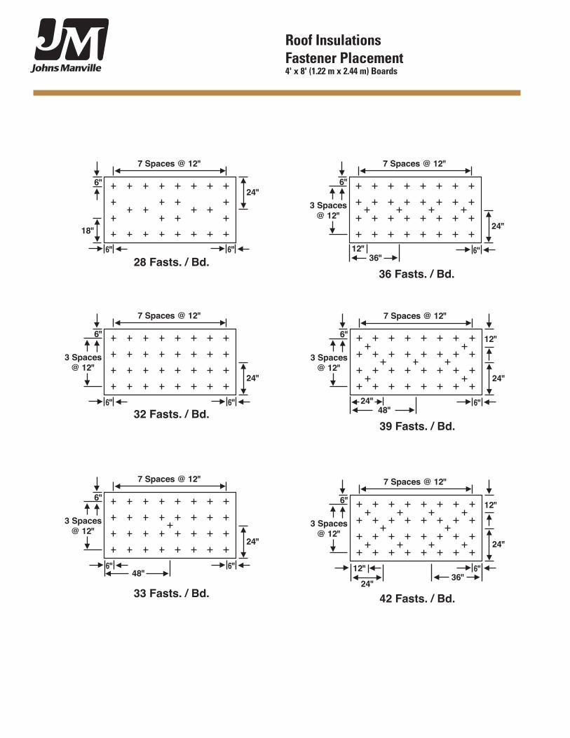
28 Fasts. / Bd.
33 Fasts. / Bd.
7 Spaces @ 12"
7 Spaces @ 12"
3 Spaces@ 12"
6" 6"
6"6"
18"
24"
24"
6"
3 Spaces@ 12"
6"
48"
36 Fasts. / Bd.
7 Spaces @ 12"
6"
24"
12"
6"
36"
36"
3 Spaces@ 12"
39 Fasts. / Bd.
7 Spaces @ 12"
6"
24"
24"
12"6"
48"
3 Spaces@ 12"
32 Fasts. / Bd.
7 Spaces @ 12"
3 Spaces@ 12"
6"6"
24"
6"
42 Fasts. / Bd.
7 Spaces @ 12"
6"
24"
24"
12"6"
12"
Roof Insulations Fastener Placement 4' x 8' (1.22 m x 2.44 m) Boards
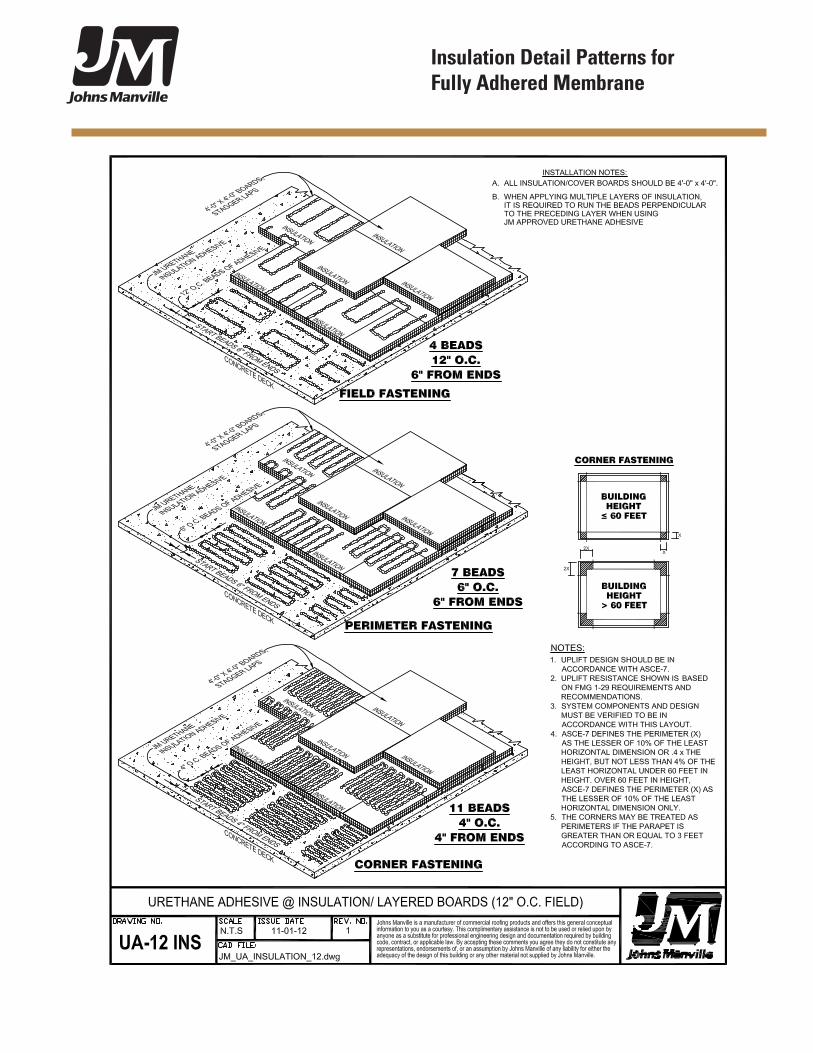
Insulation Detail Patterns for Fully Adhered Membrane
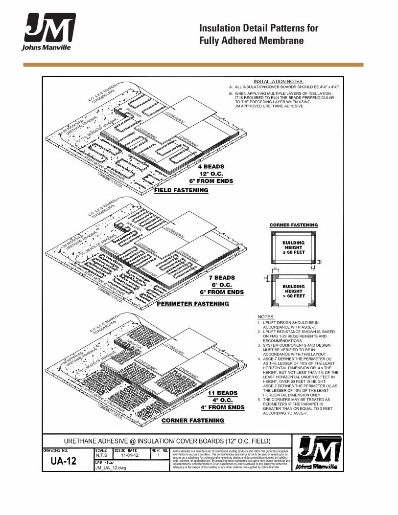
Insulation Detail Patterns for Fully Adhered Membrane