ROD ROTATORS - Confind
5
10/3/2014 1 ROD ROTATORS Starting from 2010, CONFIND began to manufacture rod rotators. Rod rotators are equipment that are installed on jack pumping units and have a significant influence over the lifetime of the equipment in the well. Fig. 1 15 to jack pump equipped with rod rotator CONFIND developed rotators up to 15 tons ( R15; R15 BP ). Installing R15 / R15 BP rotators on jack pumping units, the following effects are achieved, leading to a decrease of operational expenses: ‐ Increased life time for the equipment below : ‐ Sucker rod pump; ‐ Rod string; ‐ Tubing string; ‐ Gaskets of the stuffing box; ‐ Polished rod. This document belongs to SC CONFIND srl and contains confidential information. Upon receipt of this document, the recipient accepts that thi sis a confidential document and has to be used solely for the purpose it has been received. The receipient will return this document to SC CONFIND srl upon request.
Transcript of ROD ROTATORS - Confind

10/3/201
4
1
ROD ROTATORS
Starting from 2010, CONFIND began to manufacture rod rotators.
Rod rotators are equipment that are installed on jack pumping units and have a significant influence over the lifetime of the equipment in the well.
Fig. 1 15 to jack pump equipped with rod rotator
CONFIND developed rotators up to 15 tons ( R15; R15 BP ). InstallingR15 / R15 BP rotators on jack pumping units, the following effectsare achieved, leading to a decrease of operational expenses:
‐ Increased life time for the equipment below :
‐ Sucker rod pump;
‐ Rod string;
‐ Tubing string;
‐ Gaskets of the stuffing box;
‐ Polished rod.
This document belongs to SC CONFIND srl and contains confidential information. Upon receipt of this document, the recipient accepts that thi sis a confidential document and has to be used solely for the purpose it has been received. The receipient will return this document to SC CONFIND srl upon request.

10/3/201
4
2
Technical characteristics:‐load at polished rod……………..................................................max. 15to
‐torque at polished rod…………………………………………………….max. 165 N.m
‐polished rod diameter……………………………………………………..1” ; 1¼” ; 1½”
‐weight (rotator + driving arm)……………………………………………….......17 kg
‐gear ratio………………………………………………………………………………………...44
‐number of rotations per hour(10 double strokes/minute)………………...6
‐arm rotation angle…………………………………………………………………max ±30˚
‐maximum force at driving arm…………………………………………………..4,7daN
‐lubrication……………………………….UM185Li2M,U135Ca2G30,UM135LiCa2
Rotator construction
Rotator consists of two basic parts:‐rotator itself who generates the rotation of the sucker rods;‐rotator drive system, which provides the transmission of the movement from the beam through thedriving arm to the rotator.Rotator consists of a nodular graphite cast iron housing, a worm gear (hardened worm, nodular graphitecast iron wheel), a one way rotation system, a pressure bearing to support the weight of the rods string, acentering part for the polished rod and the locking mechanism.
This document belongs to SC CONFIND srl and contains confidential information. Upon receipt of this document, the recipient accepts that thi sis a confidential document and has to be used solely for the purpose it has been received. The receipient will return this document to SC CONFIND srl upon request.
ROD ROTATORS

10/3/201
4
3
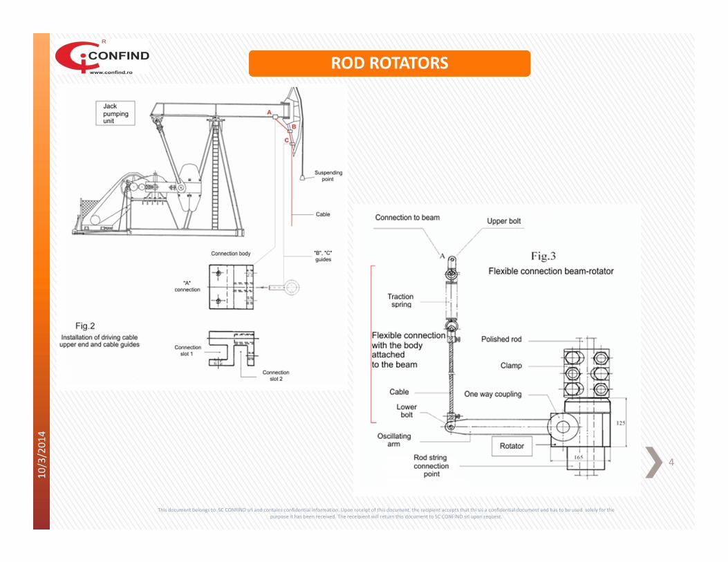
Rotator is designed to provide self brake, but for safety reasons, it is equipped with a one way system thatprevents reversing by means elastic ratchets acting on the worm. This safety system is needed due to theelasticity of the rod string who has the tendency to reverse the rotator when the beam goes up. At the outsideend of the worm shaft is installed the driving arm on a one way roll coupling.The driving system of the rotator is a flexible connection consisting of a cable, a spring and few articulatedelements.Driving cable is connected to the beam by means of a connection body and a connection eye. Cable is guidedthrough two eyes located on the sides of the front part of the beam (fig. 2).The second end of the cable is connected to a spring that is attached to the oscillating arm of the rotator.Cable length can be adjusted by using the clamp of the spring (fig. 3).
In order to minimize resistance to rotation of the rod string the active rotation of the rotator is providedduring the lowering of the beam( piston valve of the sucker rod pump is open) that corresponds to raising ofthe oscillating arm.
This is accomplished by means of a certain geometry of the system consisting of the front part of the beam,oscillating arm of the rotator, string supporting cable and flexible connection rotator to front end of the beam.
Rod string is suspended on the rotator, that in turn is supported by the front part of the beam, through aclamp. Rotation of the rod string is performed cyclically during the descending movement of the beam; duringthe ascending movement of the beam, the rotator is inactive. By means of this slow rotation motion, in thecontact points with the tubing wear of the rod string will be uniform and significantly decreased.
This document belongs to SC CONFIND srl and contains confidential information. Upon receipt of this document, the recipient accepts that thi sis a confidential document and has to be used solely for the purpose it has been received. The receipient will return this document to SC CONFIND srl upon request.
ROD ROTATORS
10/3/201
4
4
This document belongs to SC CONFIND srl and contains confidential information. Upon receipt of this document, the recipient accepts that thi sis a confidential document and has to be used solely for the purpose it has been received. The receipient will return this document to SC CONFIND srl upon request.
ROD ROTATORS
10/3/201
4
5
Design and manufacturing standards
The following standards, specifications and directives have been applied:
‐2006/42 CE – Machinery Directive‐94/9/CE ‐ Equipment and protective systems intended for use in potentially explosive atmospheres (ATEX)‐SR EN ISO 12100 ‐ Safety of machinery. Risk assessment and risk reduction.‐SR EN 1127‐1 ‐ Explosive atmospheres‐Explosion prevention and protection‐Part 1: Basic concepts andmethodology‐SR EN 13463‐1 ‐ Non‐electrical equipment for use in potentially explosive atmospheres ‐ Part 1: Basic methodand requirements‐SR EN 13463‐5 ‐ Non‐electrical equipment intended for use in potentially explosive atmospheres ‐ Part 5:Protection by constructional safety 'c'‐SR EN 10083‐1+A1:2002 ‐ Quenched and tempered steels. Part 1: Technical delivery;‐SR EN 22768‐1:1995 ‐ General Tolerances ‐ Tolerances For Linear And Angular Dimensions;‐SR EN 22768‐2 :1995 ‐ General tolerances; Part 2: Geometrical tolerances for features without individualtolerance indications.
This document belongs to SC CONFIND srl and contains confidential information. Upon receipt of this document, the recipient accepts that thi sis a confidential document and has to be used solely for the purpose it has been received. The receipient will return this document to SC CONFIND srl upon request.
ROD ROTATORS


![Rockers, Rotators and Shakers [ES]](https://static.fdocuments.net/doc/165x107/589d9b9b1a28abef498bc862/rockers-rotators-and-shakers-es.jpg)