Rockville Metro Plaza II - Pennsylvania State University Metro Plaza II ... use flat plate, two-way...
12
Rockville Metro Plaza II 121 Rockville Pike Rockville, Maryland Technical Report I PSUAE Thesis Advisor: Dr. Hanagan 9/13/2013 John Vais
Transcript of Rockville Metro Plaza II - Pennsylvania State University Metro Plaza II ... use flat plate, two-way...
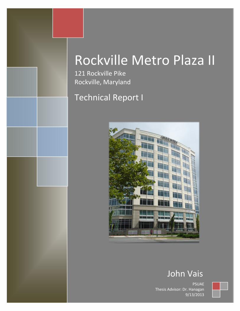
Rockville Metro Plaza II 121 Rockville Pike Rockville, Maryland
Technical Report I
PSUAE Thesis Advisor: Dr. Hanagan
9/13/2013
John Vais

John Vais Technical Report I Rockville Metro Plaza II
1 | 1 1
Table of Contents
Executive Summary . . . . . . . . . . . . . . . . . . . . . . . . . . . . . . . . . . . . . . 2
Architectural Introduction. . . . . . . . . . . . . . . . . . . . . . . . . . . . . . . . . . . 3
Structural Systems Overview . . . . . . . . . . . . . . . . . . . . . . . . . . . . . . . . . 4
Foundations . . . . . . . . . . . . . . . . . . . . . . . . . . . . . . . . . . 4
Floor System . . . . . . . . . . . . . . . . . . . . . . . . . . . . . . . . . . 5
Gravity System . . . . . . . . . . . . . . . . . . . . . . . . . . . . . . . . 6
Lateral System . . . . . . . . . . . . . . . . . . . . . . . . . . . . . . . . 7
Roof System . . . . . . . . . . . . . . . . . . . . . . . . . . . . . . . . . 7
Design Criteria. . . . . . . . . . . . . . . . . . . . . . . . . . . . . . . . . . . . . . . . . . 8
Load Analysis – Gravity. . . . . . . . . . . . . . . . . . . . . . . . . . . . . . . . . . . . . 9
Dead Load . . . . . . . . . . . . . . . . . . . . . . . . . . . . . . . . . . . 9
Live Load . . . . . . . . . . . . . . . . . . . . . . . . . . . . . . . . . . . . 9
Snow Load . . . . . . . . . . . . . . . . . . . . . . . . . . . . . . . . . . . 9
Load Analysis – Lateral. . . . . . . . . . . . . . . . . . . . . . . . . . . . . . . . . . . . . 10
Wind Load . . . . . . . . . . . . . . . . . . . . . . . . . . . . . . . . . . . . 10
Seismic Load. . . . . . . . . . . . . . . . . . . . . . . . . . . . . . . . . . . 10
Lateral Soil Load. . . . . . . . . . . . . . . . . . . . . . . . . . . . . . . . . 10
Closing . . . . . . . . . . . . . . . . . . . . . . . . . . . . . . . . . . . . . . . . . . . . . . 11
John Vais Technical Report I Rockville Metro Plaza II
2 | 1 1
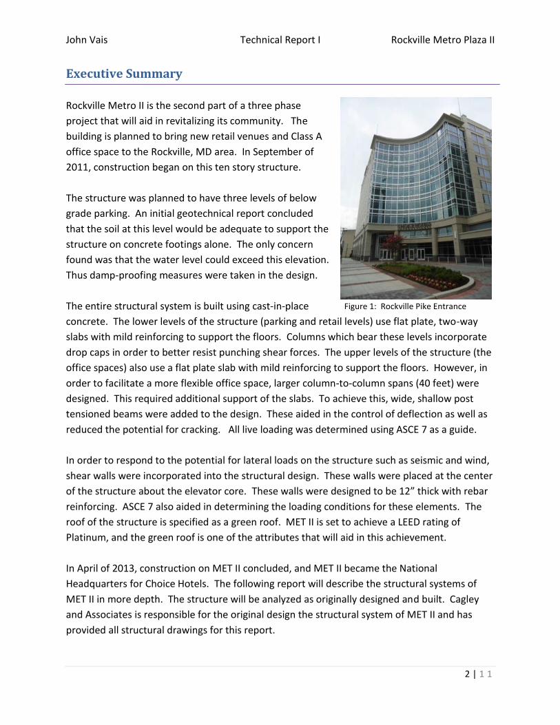
Figure 1: Rockville Pike Entrance
Executive Summary
Rockville Metro II is the second part of a three phase
project that will aid in revitalizing its community. The
building is planned to bring new retail venues and Class A
office space to the Rockville, MD area. In September of
2011, construction began on this ten story structure.
The structure was planned to have three levels of below
grade parking. An initial geotechnical report concluded
that the soil at this level would be adequate to support the
structure on concrete footings alone. The only concern
found was that the water level could exceed this elevation.
Thus damp-proofing measures were taken in the design.
The entire structural system is built using cast-in-place
concrete. The lower levels of the structure (parking and retail levels) use flat plate, two-way
slabs with mild reinforcing to support the floors. Columns which bear these levels incorporate
drop caps in order to better resist punching shear forces. The upper levels of the structure (the
office spaces) also use a flat plate slab with mild reinforcing to support the floors. However, in
order to facilitate a more flexible office space, larger column-to-column spans (40 feet) were
designed. This required additional support of the slabs. To achieve this, wide, shallow post
tensioned beams were added to the design. These aided in the control of deflection as well as
reduced the potential for cracking. All live loading was determined using ASCE 7 as a guide.
In order to respond to the potential for lateral loads on the structure such as seismic and wind,
shear walls were incorporated into the structural design. These walls were placed at the center
of the structure about the elevator core. These walls were designed to be 12” thick with rebar
reinforcing. ASCE 7 also aided in determining the loading conditions for these elements. The
roof of the structure is specified as a green roof. MET II is set to achieve a LEED rating of
Platinum, and the green roof is one of the attributes that will aid in this achievement.
In April of 2013, construction on MET II concluded, and MET II became the National
Headquarters for Choice Hotels. The following report will describe the structural systems of
MET II in more depth. The structure will be analyzed as originally designed and built. Cagley
and Associates is responsible for the original design the structural system of MET II and has
provided all structural drawings for this report.

John Vais Technical Report I Rockville Metro Plaza II
3 | 1 1
Figure 2: Exterior View from Across Rockville Pike
Figure 3: Rockville Town Square Obelisk
Architectural Introduction
Rockville Metro Plaza II is the second part of a three phase development that will bring
retail venues and Class A office space to the Rockville area. Located in Rockville, Maryland, the
site is situated on the corner of Rockville Pike and East Middle Lane, just one block from the
Rockville Metro Station and less than a mile from I-270. MET II is a ten story office structure
with three levels of underground parking and street-level retail space.
The main pedestrian
entrance for the office area is
located at grade along Rockville
Pike. Two retail spaces will flank
this entry; their door’s located
adjacently. The parking levels are
accessed via the ramp located on
the east side of Phase I. Once
completed, the parking areas of
MET II will simply be an extension
of this garage. Parking will
occupy the three below grade
levels of MET II as well as the
first elevated level. The remaining eight levels of the structure will be occupied by office
tenants. Choice Hotels is set to make this building their North American Headquarters and will
thus inhabit a large majority of this building. Topping
the structure will be the mechanical penthouse which
will house MET II’s cooling towers, generator, etc.
The structure is bound by a blanket of
architectural precast concrete panels, masonry, and
glazing. On the lower levels, a chevron shape
ornaments the precast panels and finer stone accents
the building. Sustainable attributes such as green
roofs and energy-wise mechanical systems elevate the
structure to it’s Platinum LEED certification. The
building serves as a model, revitalizing its
neighborhood economically, visually, and spiritually.
John Vais Technical Report I Rockville Metro Plaza II
4 | 1 1
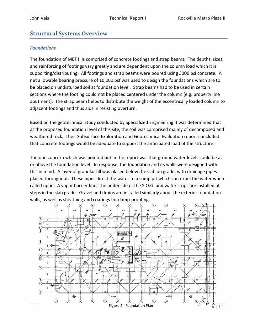
Figure 4: Foundation Plan
Structural Systems Overview
Foundations
The foundation of MET II is comprised of concrete footings and strap beams. The depths, sizes,
and reinforcing of footings vary greatly and are dependent upon the column load which it is
supporting/distributing. All footings and strap beams were poured using 3000 psi concrete. A
net allowable bearing pressure of 10,000 psf was used to design the foundations which are to
be placed on undisturbed soil at foundation level. Strap beams had to be used in certain
sections where the footing could not be placed centered under the column (e.g. property line
abutment). The strap beam helps to distribute the weight of the eccentrically loaded column to
adjacent footings and thus aids in resisting overturn.
Based on the geotechnical study conducted by Specialized Engineering it was determined that
at the proposed foundation level of this site, the soil was comprised mainly of decomposed and
weathered rock. Their Subsurface Exploration and Geotechnical Evaluation report concluded
that concrete footings would be adequate to support the anticipated load of the structure.
The one concern which was pointed out in the report was that ground water levels could be at
or above the foundation level. In response, the foundation and its walls were designed with
this in mind. A layer of granular fill was placed below the slab on grade, with drainage pipes
placed throughout. These pipes direct the water to a sump pit which can expel the water when
called upon. A vapor barrier lines the underside of the S.O.G. and water stops are installed at
steps in the slab grade. Gravel and drains are installed similarly about the exterior foundation
walls, as well as sheathing and coatings for damp-proofing.
John Vais Technical Report I Rockville Metro Plaza II
5 | 1 1
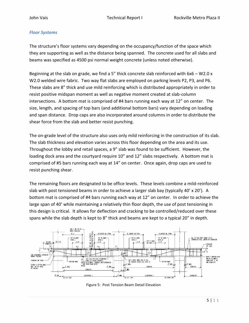
Figure 5: Post Tension Beam Detail Elevation
Floor Systems
The structure’s floor systems vary depending on the occupancy/function of the space which
they are supporting as well as the distance being spanned. The concrete used for all slabs and
beams was specified as 4500 psi normal weight concrete (unless noted otherwise).
Beginning at the slab on grade, we find a 5” thick concrete slab reinforced with 6x6 – W2.0 x
W2.0 welded wire fabric. Two way flat slabs are employed on parking levels P2, P3, and P6.
These slabs are 8” thick and use mild reinforcing which is distributed appropriately in order to
resist positive midspan moment as well as negative moment created at slab-column
intersections. A bottom mat is comprised of #4 bars running each way at 12” on center. The
size, length, and spacing of top bars (and additional bottom bars) vary depending on loading
and span distance. Drop caps are also incorporated around columns in order to distribute the
shear force from the slab and better resist punching.
The on-grade level of the structure also uses only mild reinforcing in the construction of its slab.
The slab thickness and elevation varies across this floor depending on the area and its use.
Throughout the lobby and retail spaces, a 9” slab was found to be sufficient. However, the
loading dock area and the courtyard require 10” and 12” slabs respectively. A bottom mat is
comprised of #5 bars running each way at 14” on center. Once again, drop caps are used to
resist punching shear.
The remaining floors are designated to be office levels. These levels combine a mild-reinforced
slab with post tensioned beams in order to achieve a larger slab bay (typically 40’ x 20’). A
bottom mat is comprised of #4 bars running each way at 12” on center. In order to achieve the
large span of 40’ while maintaining a relatively thin floor depth, the use of post tensioning in
this design is critical. It allows for deflection and cracking to be controlled/reduced over these
spans while the slab depth is kept to 8” thick and beams are kept to a typical 20” in depth.

John Vais Technical Report I Rockville Metro Plaza II
6 | 1 1
Figure 6: Column Detail Elevation
Figure 7: Sloped Columns in Retail Space
Gravity System
The structure of MET II is comprised of concrete columns.
The majority of the building’s columns are 24” x 24” in
dimension and are reinforced with #10 and #11 rebar. The
exterior of the building incorporates 30” diam. columns as
architectural accents. The strength of concrete used to
construct the columns is stepped down as the column
rises: 5000/6000 psi ground through the 4th level, 4000 psi
5th through the 8th level, and 3000 psi 9th level and above.
The office portion of the structure achieves a fairly
repetitive column layout. However, the exterior-to-
interior column span on each the East and West side of
the structure is 40’ in length. This architecturally driven
span allows tenants to have a wider, more flexible floor
plan. In response to this, post tension beams are used to
transfer the slab load to the columns. Within these levels,
these beams are typically 20” x 48” in dimension.
Within the parking levels an extra row of columns has
been added on each the east and west sides. This divides the otherwise 40’ span in two (thus
eliminating the need for post tension beams as seen in the upper floors). The columns in the
parking areas also incorporate drop caps in order to better resist punching shear.
In order to respond to
architectural features that stood
in the path of select columns, it
was necessary to design some
columns as sloped. On the plaza
and P6 levels, interior columns are
commonly sloped in order to
accommodate the standard
parking stall space in the garage
levels below.
John Vais Technical Report I Rockville Metro Plaza II
7 | 1 1
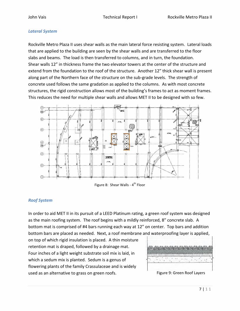
Figure 8: Shear Walls - 4th
Floor
Figure 9: Green Roof Layers
Lateral System
Rockville Metro Plaza II uses shear walls as the main lateral force resisting system. Lateral loads
that are applied to the building are seen by the shear walls and are transferred to the floor
slabs and beams. The load is then transferred to columns, and in turn, the foundation.
Shear walls 12” in thickness frame the two elevator towers at the center of the structure and
extend from the foundation to the roof of the structure. Another 12” thick shear wall is present
along part of the Northern face of the structure on the sub-grade levels. The strength of
concrete used follows the same gradation as applied to the columns. As with most concrete
structures, the rigid construction allows most of the building’s frames to act as moment frames.
This reduces the need for multiple shear walls and allows MET II to be designed with so few.
Roof System
In order to aid MET II in its pursuit of a LEED Platinum rating, a green roof system was designed
as the main roofing system. The roof begins with a mildly reinforced, 8” concrete slab. A
bottom mat is comprised of #4 bars running each way at 12” on center. Top bars and addition
bottom bars are placed as needed. Next, a roof membrane and waterproofing layer is applied,
on top of which rigid insulation is placed. A thin moisture
retention mat is draped, followed by a drainage mat.
Four inches of a light weight substrate soil mix is laid, in
which a sedum mix is planted. Sedum is a genus of
flowering plants of the family Crassulaceae and is widely
used as an alternative to grass on green roofs.

John Vais Technical Report I Rockville Metro Plaza II
8 | 1 1
Design Codes
As defined on page S1.00 of the construction documents, the following codes are
applicable to the design and construction of MET II’s structural system:
- “The International Building Code-2009”,
International Code Council
- “Minimum Design Loads for Buildings and Other Structures” (ASCE 7),
American Society of Civil Engineers
- “Building Code Requirements for Structural Concrete, ACI 318-02”,
American Concrete Institute
- “ACI Manual of Concrete Practice – Parts 1 Through 5”,
American Concrete Institute
- “Post Tensioning Manual”,
Post Tension Institute

John Vais Technical Report I Rockville Metro Plaza II
9 | 1 1
Figure 10: Precast Elevation Detail
Load Analysis - Gravity
Dead Load
Dead loads are permanent loads on a structure. Within MET
II, floor dead loads are mostly comprised of the concrete slab
itself. Reinforced, normal weight concrete is used in the
construction of slabs, thus a value of 150 pcf is appropriate as
a design value. Superimposed floor dead loads, such as
flooring or ceiling tile, contribute a smaller fraction. To
achieve an accurate design value for the superimposed load,
architectural drawings and specification cut sheets could be
analyzed. However, the assumed value as per the structural
documents is 5 psf for floors and 10 psf for roofs.
Similarly, wall dead loads have a single large contributing
component to dead loads: architectural precast concrete
panels. Aluminum-framed glass and a cold-formed steel
framed wall comprise the remainder of the wall dead load.
Live Loads
Design live loads for MET II are determined based on the function of the space being designed.
Within the structure, office, parking, corridor, retail, light storage, and stair type loading
definitions will most commonly be used in design. Upon comparison between design loads
listed on the structural documents and those suggested in ASCE 7, it can be seen that all
requirements are met. Some design loads used (mechanical and parking areas) exceeded the
required load listed in ASCE 7. These increases in load are based on engineering judgment and
owner specifications.
Snow Load
The roof of the structure is predominantly flat. Thus a flat roof snow load was used in designing
the roof’s structure. This value was determined to be 17.5 psf (reduced from a ground snow
load of 25 psf). Due to the penthouse projection and roof curb, unbalanced, drifting, and
sliding snow loads also had to be considered in the design. Procedures used for evaluating the
flat roof snow load, drifting, etc. are defined in ASCE 7.

John Vais Technical Report I Rockville Metro Plaza II
10 | 1 1
Load Analysis - Lateral
Wind Load
Wind forces act on the façade of a structure. Based on tributary area, the load would be
distributed story wise into the floor slabs of the structure (which can be considered rigid in this
model). The slab then transfers the force into the shear walls and moment frames of the
structure. In turn, the load is funneled to the foundation of the structure. In analyzing the
structure for this load case, various load combination must be considered as per ASCE 7. Due
to the building’s geometry, wind in the East-West direction would likely be the most critical
design case. This can be surmised by looking at the length of each side of the structure. The
east and west sides are nearly twice as long as their perpendicular counterparts, thus they will
have a larger tributary area and will see a stronger force.
Wind loads for this structure were calculated using the approaches listed in ASCE 7. The basic
wind speed used in design was 90 mph. The site importance factor and site exposure category
are 1.0 and B, respectively. A net wind uplift force of 25 psf was also determined. In analyzing
this system, loads would be applied to the vertical, exterior face of the structure as per ASCE 7.
Seismic Load
Seismic loads are those caused by the movement of the earth below the structure. This
movement is an oscillatory vibration of the ground surface following a release of energy in the
earth’s crust. An earthquake typically has a main shock and aftershocks. Earthquakes are
difficult to design against due to their secondary effects such as liquefaction, landslides, fire,
etc. ASCE 7 offers the guidelines for design against seismic loads that were used in the design
of MET II. The aid allows the effects of an earthquake to be simplified into a lateral load at the
base of the structure, i.e. the base shear. The base shear is a result of the relationship between
the mass at each floor, the building’s frequency, and a selected ground motion.
Lateral Soil Load
Lateral soil loads are considered in the design of the foundation walls. A lateral equivalent fluid
pressure as determined by the geotechnical report is used for this calculation. At rest condition
(braced walls), this force was determined to be 55 psf per foot of depth. For the active
condition (cantilevered retaining walls), this value was determined to be 45 psf per foot of
depth. These values may then be used to design the foundation walls as guided by ACI 318-02.
John Vais Technical Report I Rockville Metro Plaza II
11 | 1 1
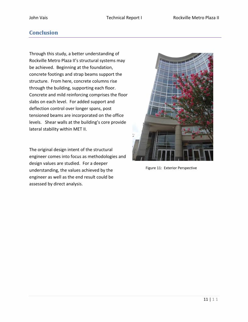
Figure 11: Exterior Perspective
Conclusion
Through this study, a better understanding of
Rockville Metro Plaza II’s structural systems may
be achieved. Beginning at the foundation,
concrete footings and strap beams support the
structure. From here, concrete columns rise
through the building, supporting each floor.
Concrete and mild reinforcing comprises the floor
slabs on each level. For added support and
deflection control over longer spans, post
tensioned beams are incorporated on the office
levels. Shear walls at the building’s core provide
lateral stability within MET II.
The original design intent of the structural
engineer comes into focus as methodologies and
design values are studied. For a deeper
understanding, the values achieved by the
engineer as well as the end result could be
assessed by direct analysis.