Robotic Transfer and Interfaces for External ISS Payloads
34
Robotic Transfer and Interfaces for External ISS Payloads 1 3 rd Annual ISS Research and Development Conference June, 2014 Phillip Callen Software, Robotics, and Simulation Division Engineering Directorate NASA/JSC https://ntrs.nasa.gov/search.jsp?R=20140008717 2018-02-16T03:09:27+00:00Z
-
Upload
phungthien -
Category
Documents
-
view
225 -
download
1
Transcript of Robotic Transfer and Interfaces for External ISS Payloads

Robotic Transfer and Interfaces for External ISS Payloads
1
3rd Annual ISS Research and Development ConferenceJune, 2014
Phillip CallenSoftware, Robotics, and Simulation DivisionEngineering DirectorateNASA/JSC
https://ntrs.nasa.gov/search.jsp?R=20140008717 2018-02-16T03:09:27+00:00Z

External payloads will be interacting with ISS robotic systems in one way or another.
Robots on ISS provide a lot of flexibility, but that also brings increased options and complexity that must be taken into account.
The purpose of this presentation is to provide an overview of the robotic systems and the options available.
Agenda• Robotic Systems• Transport• Payload Locations• Payload Interfaces• Robotic Forums (How To Get Started)
2

3
ISS Robotic Systems
Space Station Remote Manipulator System (SSRMS)
JEM Remote Manipulator System (JEM RMS)
Special Purpose Dexterous Manipulator (SPDM)
Mobile Base System (MBS)On Mobile Transporter (MT)
EVA Crewman(for scale)

4
ISS Robots

5
JEM RMS
6
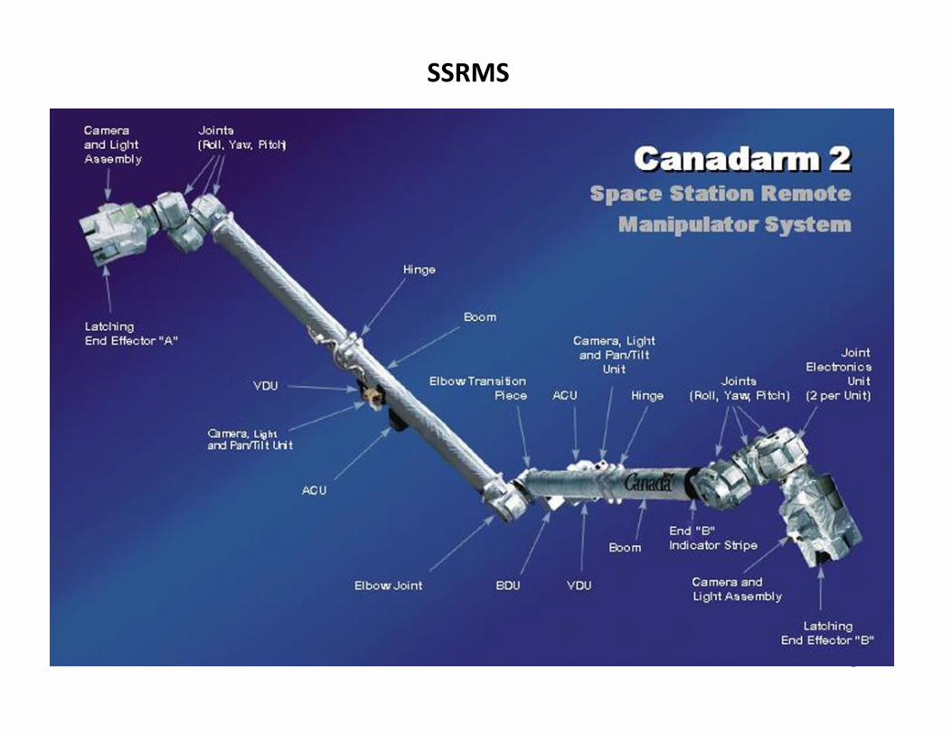
SSRMS

7
1. Two ORU/Tool Changeout Mechanisms (OTCMs)
2. Two arms3. Power & Data Grapple Fixture (PDGF)4. Two Electronics Platforms5. Two Camera/Light/Pan‐Tilt Assemblies
(CLPAs); 6. Body Roll Joint7. Tool Holder Assembly (THA)
a) 2 Robot Micro Conical Tools (RMCTs)
b) Socket Extension Tool (SET)
c) Robotic Offset Tool (ROST)
8. Enhanced ORU Temporary Platform (EOTP) with 2 PFRAMs and 3 Stanchion sets
9. SPDM Latching End Effector (LEE) with Camera/Light Assembly (CLA)
1
22
9
34
4
5
5
78
6
1
SPDM Component Overview

8
Light
OTVC
Light
Umbilical
Gripper
EVA Drive Bolt
Socket Drive
ORU Tool Change‐out Mechanism (OTCM)

9
SSRMS with SPDM

Transportation – How To Get To ISS And Why It Matters
Internally and Externally Launched Payload Capable
Internally Launched Payload Capability Only
JAXA HTVSpaceX Dragon Orbital Cygnus ESA ATV
Dragon “Trunk”
10
Exposed Pallet (EP)
Payload must use JEM Airlock to get external and then installation via robotics
Direct installation to ISS location via robotics
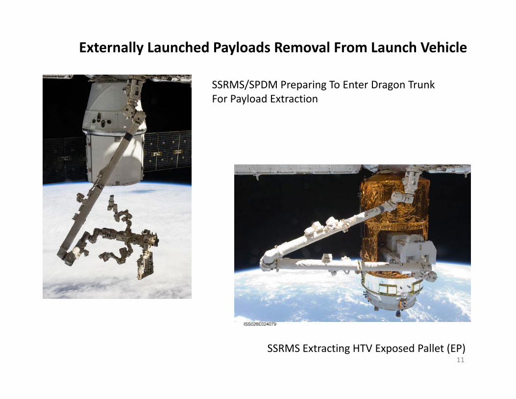
Externally Launched Payloads Removal From Launch Vehicle
11
SSRMS/SPDM Preparing To Enter Dragon Trunk For Payload Extraction
SSRMS Extracting HTV Exposed Pallet (EP)

12
EP Installed on JEM EF
Payloads will be removed from EP and installed on ISS (either JEM EF or ELCs)

• For payloads that plan to launch internally, but then go external, the only robotic option is to go through the JEM Airlock
• There are three primary JEM Airlock interfaces for SPDM ops– Capture type – requires a specific slide table interface on the payload– Bolt‐fixed type (Direct Mount) – payload carrier bolts directly to the slide table which
would necessitate a robotically‐actuated payload release interface between the payload and the carrier
– JEM ORU Transfer Interface (JOTI) – does not require any specific payload interfaces which allows it to accommodate hardware not specifically designed to utilize the native JEM Airlock interfaces
13
JEM Airlock Table with Payload Installed (capture type)JEM Airlock and Slide Table
JEM Airlock Usage

JEM Airlock Envelope(with JOTI installed for reference)
32.7”
54.3”
25.5”
14

15
JEM Slide Table(existing)
Slide Table Active Mechanism (existing) Provides Motion Control
Floor
Fixed EndActive End
Open Cell Foam
Hard Stop
Restraint Fingers
Contingency Mechanism
MBSU
JEM ORU Transfer Interface (JOTI)
Payload constrained by JOTI walls(in airlock envelope)
CLPA in JOTI

Payload Interfaces
SSRMS InterfacesFlight Releasable Grapple FixtureLatchable Grapple FixturePower and Video Grapple Fixture
SPDM InterfacesH‐fixtureMicro‐squareMicro‐Conical
Robotic Interfaces for Transport
Interfaces for Launch or ISS Location
JEM RMS InterfacesFlight Releasable Grapple Fixture
FRAM, JEM EFU, Payload Unique16
Payload
I/F
I/F

17
External Payload Locations Where You Go Determines Type Of ISS Interface

Payload interface to JEM EF is the EFU18
JEM Payload Sites
Robotic interface to Payload is FRGF

Gripper Attach Options Provides Extensive Location Options• Handrails• Micro Fixture• WIF Socket
Gripper InterfaceProvides Bolted AttachmentFor TBD Hardware
Robonaut2 Gripper
SPDM OTCM
Grasp Fixture
Payload
Gripper Interface Concept(not existing capability)
WIF Socket Locations
Payload Attached To Handrail
Payload would need to provide power and data (wi‐fi)
19

20
Interfaces for Launch or ISS Location
The payload and the Active FRAM interface are both attached to and separated by an adapter plate. There are different sizes of adapter plates that can be used:• Large Adapter Plate Assembly (LAPA)• Medium Adapter Plate Assembly (MAPA)• Small Adapter Plate Assembly (SAPA)• Light‐Weight Adapter Plate Assembly (LWAPA)
Flight Releasable Attachment Mechanism (FRAM).
Robotic Interface is with the FRAMand not the payload
Compatible with Dragon Trunk, HTV EP and ELCs

• For payloads that require a direct interface with the SSRMS (or POA or SPDM LEE), there are a few different interfaces to be aware of:
– Flight Releasable Grapple Fixture (FRGF)• Simplest grapple fixture – only allows for grapple
– Latchable Grapple Fixture (LGF)• Allows for grapple and latching• Intended to be used for longer‐term stowage on the POA (greater than 3 weeks)
– Power and Video Grapple Fixture (PVGF)• Allows for grapple, latching, and access to data, video, and power• Connectors for data/video/power integrated into the fixture
– Power and Data Grapple Fixture (PDGF)• Allows for grapple, latching, and access to data, video, and power• Connectors for data/video/power integrated into the fixture• Only fixture that is an On‐orbit Replaceable Unit (ORU)
21
SSRMS Interface Hardware

22
FRGF PDGF
PVGF (grapple shaft not shown)LGF
LEE
SSRMS Interface Hardware

• For payloads that require a direct interface with the SPDM, there are a few different interfaces to be aware of:
– H‐fixture – allows for direct grasp by SPDM ORU Tool Changeout Mechanism (OTCM)• Typically used on heavier payloads or where a “beefed up” interface is required (assumes attachment
structure can withstand the higher loads)• Allows for use of an umbilical connector and/or a co‐located bolt• Requires enough space to accommodate the SPDM OTCM
– Micro‐fixture (also known as a Micro‐square) – allows for direct grasp by SPDM OTCM• This is the “standard” grasp fixture
– MMF found on FRAMs is a version of this fixture• Allows for use of an umbilical connector and/or a co‐located bolt• Requires enough space to accommodate the SPDM OTCM
– Micro‐Conical Fitting (MCF) – allows for grasp by Robot Micro‐Conical Tool (RMCT)• Used when there is not enough space for the SPDM OTCM to access the fixture, but requires the SPDM to
acquire a tool (RMCT) which has operational overhead associated with it• Allows for use of a co‐located bolt, but not an umbilical connector
– Modified Truncated Cone (MTC) Target• Co‐located with the grasp fixture and used to line up SPDM OTCM/RMCT for grasping
– Other target types are listed in documentation, but this is the standard target type• Requires enough space to allow unobstructed viewing during approach
– Umbilical Connector• Provides access to power, data, and video connections through the SPDM OTCM• Cannot be used in conjunction with an MCF
23
SPDM Interface Hardware

Interface Hardware (cont.)
24
H‐Fixture Micro‐fixture Micro‐Conical Fitting (MCF)
User Umbilical Connector Modified Truncated Cone (MTC) Target
RobotMicro‐ConicalTool(RMCT)
25
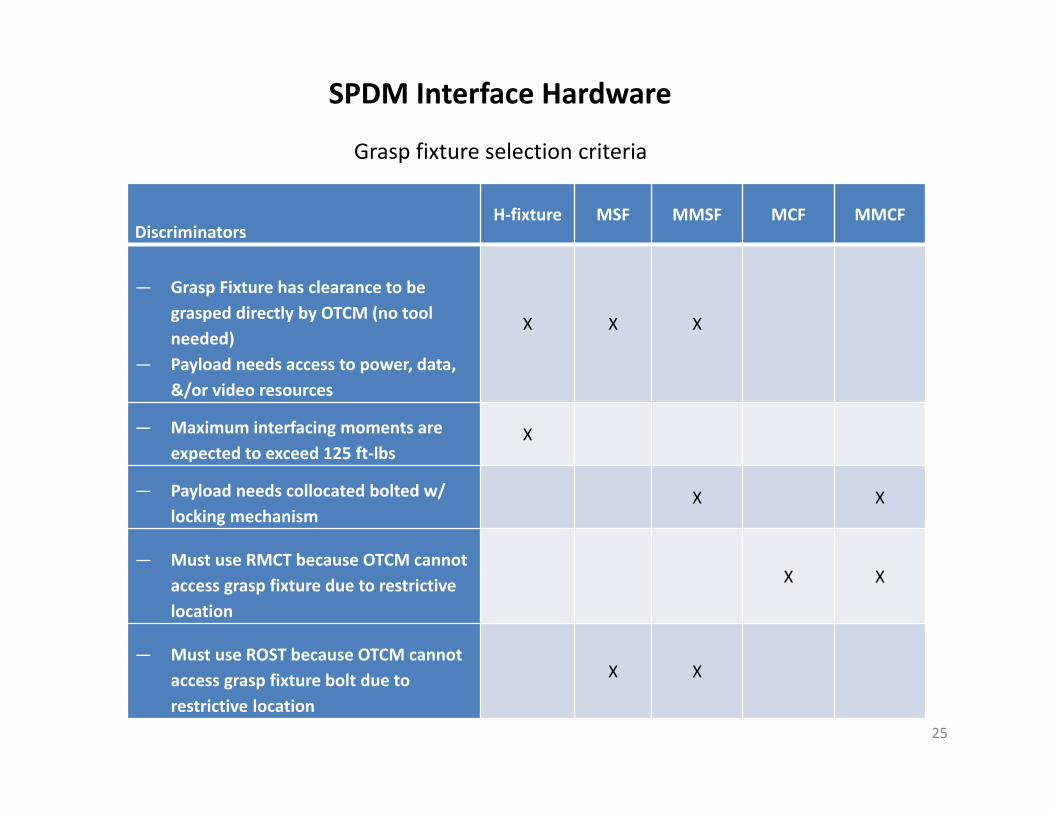
DiscriminatorsH‐fixture MSF MMSF MCF MMCF
— Grasp Fixture has clearance to be grasped directly by OTCM (no tool needed)
— Payload needs access to power, data, &/or video resources
X X X
— Maximum interfacing moments are expected to exceed 125 ft‐lbs
X
— Payload needs collocated bolted w/ locking mechanism
X X
— Must use RMCT because OTCM cannot access grasp fixture due to restrictive location
X X
— Must use ROST because OTCM cannot access grasp fixture bolt due to restrictive location
X X
SPDM Interface Hardware
Grasp fixture selection criteria

• Envelope, CG, Inertia, Mass for SPDM operations – SSP 41167, MSS Segment Spec Tables IV and XXXVIII– SSP 57003, Attached Payload IRD, Table 3.7.4.2‐1
26
Question: Which robot (SSRMS or SPDM) do you use?Answer: Primarily driven by mass handling requirements

Payload Examples of Robotic Interfaces
27
SPDM to payload I/F – Micro Fixture
Since the individual components are intended to be changed out robotically, the payload to FRAM I/F must be robotically compatible
Robotic Refueling Mission (RRM) is a FRAM based payload (on SPDM EOTP for transport)
RRM uses SPDM as part of the payload to perform refueling tasks. RRM built unique tools for the SPDM

• DRIT – Dexterous Robotics Integration Team– Mondays, 2:00 PM Central– Co‐chairs: OM7 and CSA– https://iss‐www.jsc.nasa.gov/nwo/seio/robotics/home/web/DRIT.shtml
• EBIT – Extraction and Berthing Integration Team– Wednesdays, 1:00 PM Central– Co‐chairs: OM7 and CSA– https://iss‐www.jsc.nasa.gov/nwo/seio/robotics/ebit/web/
• MSS SEWG – MSS System Engineering Working Group– Every other Tuesday (generally alternating with the MIP), 8:30 AM Central– Co‐chairs: ER3 and CSA– https://iss‐www.jsc.nasa.gov/nwo/seio/robotics/home/web/SEWG.shtml
• MSWG – MSS Software Working Group– Every other Thursday, 1:00 PM Central– Co‐chairs: OD and CSA– http://iss‐www.jsc.nasa.gov/nwo/avionics/ip/home/web/MeetingInformation.shtml
• MIP – MSS Integration Panel– Every other Tuesday (generally alternating with the MSS SEWG), 8:30 AM Central– Co‐chairs: OM7 and CSA– https://iss‐www.jsc.nasa.gov/nwo/ppco/cbp/web/mip.shtml
28
Robotics Forums(How To Get Started)

• Why go to the DRIT?– Review of SPDM‐related analysis (MAGIK, CSA, etc.)
• For example, fixture location and manifest location– Requests for or exchange of SPDM‐related information– Review SPDM‐related requirements exceptions– Review of SPDM‐related schedules– Track the need for other subsystem analyses prior to performing dexterous ops– Primary participants: OM7, CSA, ER3, MOD Robotics
• Why go to the EBIT?– Review of SSRMS‐related analysis (MAGIK, CSA, etc.)
• For example, fixture location and manifest location– Requests for or exchange of SSRMS‐related information
• Grapple fixture substrate loads for example– Review SSRMS‐related requirements exceptions– Review of SSRMS‐related schedules– Primary participants: OM7, CSA, ER3, MOD Robotics
29
Robotics Forums

• Why go to the MSS SEWG?– Technical discussions of system‐wide topics– MSS requirements technical discussions– Primary participants: ER3, CSA, OM7, MOD Robotics, Safety, Crew Office
• Why go to MSWG?– Payload data or commanding through the MSS– Primary participants: ISS Software & Avionics (OD), CSA, OM7, ER3, MOD Robotics,
Safety, Crew Office
• Why go to the MIP?– “Front door” to the ISS Program for robotics‐related topics– Introduce new payloads to NASA and CSA robotics community– Requests for information that could not be provided through the DRIT or EBIT– Review of MSS schedules– Review of MSS changes– Primary participants: OM7, CSA, ER3, MOD Robotics, Safety, Crew Office, ISS Software &
Avionics (OD)
30
Robotics Forums
• The robotics community (ER3, OM7, CSA, and MDA) is here to help. This slide has all the robotics POCs. CSA and MDA are the technical authority on the MSS and are engaged via the various robotics forums as shown on the previous slides
• ER3 – Robotics System Management and Engineering Support– MSS System Manager – Larry Grissom (281‐483‐9525, [email protected])– Deputy MSS System Manager and SSRMS Subsystem Manager – Glenn Jorgensen (281‐244‐6565,
glenn.jorgensen‐[email protected])– SPDM Subsystem Manager and SPDM Requirements lead – Michael Wright (281‐483‐4798,
[email protected])– SSRMS Requirements lead – Kendrick Cheatham (281‐244‐6744, kendrick.cheatham‐[email protected])
• OM7 – Robotics System Engineering and Integration– Manager, Robotics Integration Office – Michael Berdich (281‐244‐7957,
[email protected])– Robotics System Integration Lead – David Read (281‐244‐2212, david.read‐[email protected])– JEM Airlock Integration Lead – Chris Wade (281‐244‐2812, [email protected])– Software Integration Lead – Deep Patel (281‐244‐8269, deep‐patel‐[email protected])
31
Robotics POCs

• Robotic systems are available to support payload installation, operations, and removal.
• Robotic systems provide a lot of flexibility and options for payload users in order to meet their objectives.
• However, that flexibility also means there is additional complexity in the trade space for what options and services to utilize so working early with the robotics community is strongly encouraged.
32
Conclusion
33
Backup
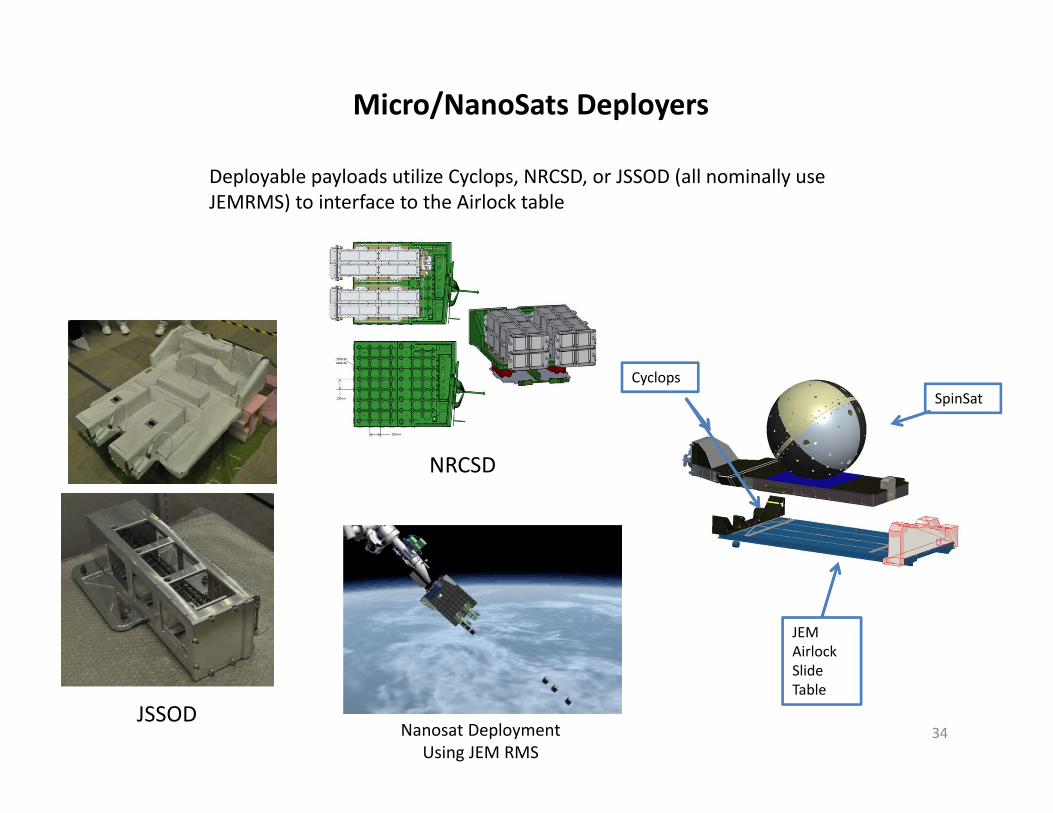
Deployable payloads utilize Cyclops, NRCSD, or JSSOD (all nominally use JEMRMS) to interface to the Airlock table
34
SpinSatCyclops
JEM Airlock Slide Table
Micro/NanoSats Deployers
JSSOD
NRCSD
Nanosat DeploymentUsing JEM RMS