Payload Safety Review and Data Submittal Requirements 13830.pdf · NSTS/ISS 13830 Revision C ....
69
NSTS/ISS 13830 Revision C Payload Safety Review and Data Submittal Requirements For Payloads Using the: - Space Shuttle - International Space Station July 1998 National Aeronautics and Space Administration Lyndon B. Johnson Space Center Formerly: NSTS 13830, “Implementation Procedure for NSTS Payloads System Safety Requirements for Payloads Using the Space Transportation System”
Transcript of Payload Safety Review and Data Submittal Requirements 13830.pdf · NSTS/ISS 13830 Revision C ....
NSTSISS 13830 Revision C
Payload Safety Review and Data Submittal Requirements
For Payloads Using the - Space Shuttle - International Space Station
July 1998
National Aeronautics and Space Administration Lyndon B Johnson Space Center
Formerly NSTS 13830 ldquoImplementation Procedure for NSTS Payloads System Safety Requirements for Payloads Using the Space Transportation Systemrdquo
iv
NSTSISS 13830
DESCRIPTION OF CHANGES TO
PAYLOAD SAFETY REVIEW AND
DATA SUBMITTAL REQUIREMENTS
CHANGE NO DESCRIPTIONAUTHORITY DATE PAGES AFFECTED
--
REV A
Basic issue
General revision
All
All
REV B General revision 020494 All
REV C General revisionR13830-002-003 PRCBD NO A096069
071398 All
1 Update table of contents sections 631 641 651 721 722 723 732 762 763 78 7111 7112 7113 822 9 and appendixes A and B add new sections 712 through 7123R13830-0005
020299 TOC1919A2122 232424A282930 31323333A33B 33C33D353637 A-2A-3B-2B-3
2 Update section 431R13830-0007 022301 66A7
Errata to correct change 2 document footer 041701 66A7
3 Update sections 572 641 651 822 and 9 R13830-0006
060101 1422243537
4 Update table of contents sections 431 631 641 651 and add new section 713R13830-0008-0009
011802 viiviii61919A22 22A24A33D33E
5 Update sections 631 641 651 and 111R13830-0010
032503 1919A212439
6 Update table of contents sections 431 641 72 9 111 and add new sections 32 78c 4315 43151 and 43152R13830-0011-0013
011404 iiiviviiviii33A68 8A22283333A33B 33C33D33E33F37 39
Note Dates reflect latest signature date of CRs received by PILS
PREFACE
DATE July 13 1998
This requirements document assists organizations that are developing payloads intended for flight on the International Space Station (ISS) andor Space Shuttle to comply with system safety requirements established by the National Aeronautics and Space Administration (NASA) The requirements for safety analyses and assessment reviews are explained in detail for flight safety and ground safety Flight safety reviews are performed by the Lyndon B Johnson Space Center (JSC) Payload Safety Review Panel (PSRP) and ground safety reviews are performed by the John F Kennedy Space Center (KSC) Ground Safety Review Panel (GSRP) Instructions are given for documenting compliance with the safety requirements
National Space Transportation System (NSTS)ISS 13830 C supersedes NSTS 13830 Bdated November 15 1989
Signed by Richard N Richards Signed by Jay H GreeneRichard N Richards Jay H GreeneManager Space Shuttle Deputy Manager for TechnicalProgram Integration Development International SpaceJohnson Space Center Station Program
Johnson Space Center
Signed by P Thomas Breakfield IIIP Thomas Breakfield III Director of Safety andMission Assurance Kennedy Space Center
13830 REV C ii CHANGE NO 6 011404
TABLE OF CONTENTS
Section Page
1 INTRODUCTION 1
2 PURPOSE 2
3 SCOPE 3
31 APPLICABLE HARDWARE 3
32 EXPORT CONTROL 3
4 RESPONSIBILITIES OF THE PAYLOAD ORGANIZATION 4
41 SAFETY ANALYSIS 4
411 Level of Analysis 4
412 Analysis Techniques 4
413 Safety Verifications for Payloads with Catastrophic Hazard Potential (Flight Only) 5
42 HAZARD IDENTIFICATION 5
43 DOCUMENTATION OF COMPLIANCE WITH THE SAFETY REQUIREMENTS 6
431 Data Submittals 6
432 Hazard Reports 8
44 SAFETY REVIEW PRESENTATION 9
5 SAFETY REVIEW OVERVIEW 10
51 LOCATION 10
52 INITIAL CONTACT MEETING 10
53 TYPES OF MEETINGS 10
54 PAYLOAD CATEGORIES 11
541 Review Process for Basic Payloads (Flight Only) 12
542 Review Process for Intermediate Payloads (Flight Only) 12
55 SCHEDULE OF REVIEWSPHASES 12
13830 REV C iii CHANGE NO 6 011404
Section Page
56 SAFETY REVIEW COMPLETION 13
561 Documentation of Phase Completion 13
562 Completion Criteria for Phase I II and III 13
563 Completion Criteria for SeriesReflight 14
57 POST PHASE III SAFETY ACTIVITY 14
571 Certificate of Flight Payload Safety Compliance 14
572 Configuration Control 14
573 Verification Tracking Log 14
574 Documentation of Safety Process Completion 15
6 SAFETY PROCESS 16
61 GENERAL 16
611 Preparation 16
612 General Meeting Agenda Guidelines 16
62 PHASE 0 SAFETY REVIEW 17
621 Phase 0 Data Requirements 18
622 Phase 0 Hazard Reports 18
63 PHASE I SAFETY REVIEW 18
631 Phase I Data Requirements 19
632 Phase I Hazard Reports 20
64 PHASE II SAFETY REVIEW 20
641 Phase II Data Requirements 21
642 Phase II Hazard Reports 23
13830 REV C iv CHANGE NO 6 011404
Section Page
65 PHASE III SAFETY REVIEW 23
651 Phase III Data Requirements 23
652 Phase III Hazard Reports 25
653 Phase III Verification Tracking Log 26
7 SUPPORTING TECHNICAL DATA SUBMITTALS 27
71 STRUCTURES 27
711 Phase I 27
712 Phase II 27
713 Phase III 27
72 PRESSURIZED SYSTEMS (vessels lines fittings components) 28
721 Phase I 28
722 Phase II 28
723 Phase III 29
73 PYROTECHNIC DEVICES 29
731 Phase I 29
732 Phase II 30
733 Phase III 30
74 MATERIAL FLAMMABILITY TOXICITY AND COMPATIBILITY 30
741 Phase I 30
742 Phase II 30
743 Phase III 30
75 IONIZING RADIATION 31
751 Phase I 31
752 Phase II 31
13830 REV C v CHANGE NO 6 011404
Section Page
753 Phase III 31
76 NON-IONIZING RADIATION 31
761 Phase I 31
762 Phase II 31
763 Phase III 31
77 PAYLOAD COMMANDING 32
771 Phase I 32
772 Phase II 32
773 Phase III 32
78a ELECTRICAL (POWER BONDING AND GROUNDING)SUBSYSTEMS 32
78a1 Phase I 32
78a2 Phase II 32
78a3 Phase III 32
78b AVIONICS CONTROL 32
78b1 Phase I 32
78b2 Phase II 32
78b3 Phase III 33
78c COMPUTER SYSTEMS (Avionics) 33
78c1 Phase I 33
78c2 Phase II 33
78c3 Phase III 33
79 MECHANISMS IN CRITICAL APPLICATIONS 33A
791 Phase I 33A
792 Phase II 33A
793 Phase III 33A
13830 REV C vi CHANGE NO 6 011404
Section Page
710 SOLID ROCKET MOTORS 33A
7101 Phase I 33A
7102 Phase II 33B
7103 Phase III 33B
711 BATTERIES 33B
7111 Phase I 33B
7112 Phase II 33B
7113 Phase III 33C
712 FLUID PROPULSION SYSTEMS 33C
7121 Phase I 33C
7122 Phase II 33D
7123 Phase III 33E
713 SEALED CONTAINERS (STRUCTURES) 33E
7131 Phase I 33E
7132 Phase II 33F
7132 Phase III 33F
8 VARIATIONS OF THE SAFETY REVIEW PROCESS 34
81 VARIATIONS FOR INTEGRATED MULTIPAYLOAD CARGO COMPLEMENTS 34
82 VARIATIONS FOR ISS PAYLOADS 34
821 On-orbit Reconfigured Payloads 34
822 Payloads Returning to Earth 35
9 REFLOWN AND SERIES PAYLOAD HARDWARE 36
10 PAYLOAD SAFETY NONCOMPLIANCE REPORT 38
101 NCR SUBMITTAL 38
13830 REV C vii CHANGE NO 6 011404
Section Page
102 TYPES OF SAFETY NCRs 38
1021 Waivers 38
1022 Deviations 38
11 LIST OF FORMS 39
111 JSC FORMS 39
112 KSC FORMS 39
12 APPLICABLE DOCUMENTS 40
APPENDIX A DOCUMENT MATRIX A-1
APPENDIX B ACRONYM LIST B-1
13830 REV C viii CHANGE NO 6 011404
SECTION 1 INTRODUCTION
Implementation of the payload safety process is the joint responsibility of the Payload Organization (PO) the flight operator Lyndon B Johnson Space Center (JSC) and the launchlanding site operator John F Kennedy Space Center (KSC)
The International Space Station (ISS) and Space Shuttle Program (SSP) safety policies and requirements for ISS and Shuttle payloads are specified in the current version of NSTS 17007ldquoSafety Policy and Requirements for Payloads Using the Space Transportation Systemrdquo and the current version of the NSTS 17007 ISS Addendum ldquoSafety Policy and Requirements for Payloads Using the International Space Stationrdquo In addition unique ground safety policies and requirements are specified in the current version of 45 SPW HB S-100KHB 17007 ldquoSpace Shuttle Payload Ground Safety Handbookrdquo These documents require the PO to conduct asystematic safety analysis and to document and submit a Safety Data Package (SDP) in support of safety reviews to be conducted by the flight operator (JSC) and the launchlanding site operator (KSC)
National Aeronautics and Space Administration (NASA) Headquarters has assigned the responsibility to review submitted payload safety documentation to the Space Shuttle and Space Station Program Directors at JSC and the Director of Safety and Mission Assurance at KSC The JSC Payload Safety Review Panel (PSRP) will assess the payload design and flight operations the KSC Ground Safety Review Panel (GSRP) will assess the Ground Support Equipment (GSE) design and ground operations These two panels were formed to accomplishthe following
bull Assure that PO interpretation of the safety requirements is consistent with NASA payload safety policy
bull Conduct safety reviews as appropriate during the development of the payload associated GSE and related operations
bull Evaluate hazard analyses and Noncompliance Reports (NCRs) bull Negotiate the resolution of safety issues involving design and operation to ensure compliance
with all applicable safety requirements bull Assess payload design features that have been implemented for controlling identified hazards
and the verification approach that confirms intended system performance
13830 REV C 1 CHANGE NO 6 011404
SECTION 2 PURPOSE
The purpose of this document is to define the payload safety review process in order to assist the ShuttleISS POs in documenting compliance with the payload requirements documents specified in section 1 Specifically this document accomplishes the following
bull Defines the safety reviews necessary to comply with the system safety requirements that are applicable to payload design flight operations GSE design and ground operations for both ISS and Space Shuttle
bull Identifies the required content of the SDP bull Describes preparation for and conduct of the safety review bull Establishes the timeline for data submittal and establishes the depth of detail required for the
various submittals bull Explains safety review process variations bull Defines the payload seriesreflight review process
13830 REV C 2 CHANGE NO 6 011404
SECTION 3 SCOPE
Data submittal requirements included herein apply to hardware being submitted to both the PSRP and the GSRP unless specified otherwise This document outlines the minimum data submittal requirements the PSRP and the GSRP reserve the right to request additional data as deemed necessary to support safety documentation
The objective of the safety review process is to review the payload GSE and operations for adequate safety implementation The mission success and any scientific objectives of the payload are the responsibility of the PO and are beyond the scope of this document and process
This document does not establish design requirements
31 APPLICABLE HARDWARE
This document applies but is not limited to the following payload hardware that fliesoperates on the Space Shuttle andor ISS during any mission phase (prelaunch launch ascent on-orbit entry landing or postlanding)
bull New Payload Hardware bull Existing (reflown and series) Payload Hardware bull Hardware Associated with Developmental Test Objectives (DTOs) Detailed Supplemental
Objectives (DSOs) Risk Mitigation Experiments (RMEs) Space Medicine Program (SMP) and Human Exploration and Development of Space Technology Demonstrations (HTDs) Experiment Hardware
The document also applies but is not limited to the following payload-related hardware
bull Government-Furnished Equipment (GFE) bull Airborne Support Equipment (ASE) bull GSE
32 EXPORT CONTROL
The PSRP complies with the United States export control laws and regulations as established by the US Department of Commerce in the Export Administration Regulations (EAR) and the US Department of State in the International Traffic in Arms Regulations (ITAR) The PSRP also complies with the Space Shuttle Programrsquos export control policy in NSTS 07700 Volume V and the ISSPrsquos export control policy in SSP 50223
13830 REV C 3 CHANGE NO 6 011404
Export control factors significantly into two areas of the payload safety review process
bull Distribution of Payload Data
bull Conduct of Safety Reviews
The PSRP Executive Secretary serves as the primary exporter of payload data to the ISS International Partners (IPs) and other foreign persons in support of the payload safety review process Payload data includes safety data packages hazard reports safety review presentation materials and other payload related information Specific export control data submittalrequirements for payload organizations are listed in section 4315 of this document
The PSRP Executive Secretary takes special precautions when conducting safety reviews for payloads under export control restrictions These precautions may include restricting attendance limiting presentation materials posting signs or conducting the review in a secure facility
13830 REV C 3A CHANGE NO 6 011404
SECTION 4 RESPONSIBILITIES OF THE PAYLOAD ORGANIZATION
The PO is responsible for assuring the safety of its payload and for complying with the safety requirements contained in the technical requirements documents cited in section 1 To this end the PO must accomplish the following
bull Perform a Safety Analysis bull Identify Hazards bull Document Compliance with the Safety Requirements bull Present the Documentation to the PSRPGSRP
41 SAFETY ANALYSIS
To meet the requirements of the current version of NSTS 17007 and NSTS 17007 ISS Addendum paragraph 301 the PO shall perform a safety analysis of the payload and GSE The analysis shall consider hardware design verification testing and flightground operations The safety analysis shall begin during the payload concept phase and shall be refined and expanded as the design matures For situations in which payload hardware will be installed orreconfigured on-orbit or in which the payload will be on-orbit for an extended time safety analyses shall consider the necessity of on-orbit verificationreverification of hazard controls
411 Level of Analysis
In order to identify the hazards applicable to a payload the PO shall conduct safety analyses both at the system and subsystem levels Each system and subsystem shall be evaluated to determinethe applicability of each technical safety requirement
Selection of subsystem groupings varies and any convenient grouping may be used The following is a suggested list of subsystems biomedical caution and warning cryogenic electrical environmental control human factors hydraulics materials mechanical opticalpressure systems propulsion pyrotechnics radiation and structures
For hardware developed for or provided to the PO the PO shall
bull Obtain the appropriate safety data from the supplier or conduct an independent safety analysis
bull Conduct a safety analysis of the interfaces between the subject hardware and other elements
412 Analysis Techniques
Depending on the complexity of the payload the PO should use established analytical techniques (eg preliminary hazard sneak circuit fault tree operational hazard and failure modes and effects analyses) to obtain the data necessary to complete present and support payload hazard reports
13830 REV C 4 CHANGE NO 6 011404
413 Safety Verifications for Payloads with Catastrophic Hazard Potential (Flight Only)
The current version of NSTSISS 18798 specifies data requirements to document the verification program for payload systemssubsystems that have catastrophic hazard potential An excerpt from this document is included below for convenience
Table 4-1 - NSTSISS 18798
All payload systems having catastrophic hazard potential for the orbiter or crew as a result of operations in or near the orbiter must use hardware and procedures that have been subjected to a rigorous verification program Verification programs normally require testing to verify adequate performance margins under all environmentalconditions (qualification testing) as well as demonstrating intended system performance on flight hardware Comprehensive system-level testing on payload flight hardware supported by qualification test on protoflight or flight type hardware are the preferred verification methods It is essential that payload system performance be verified from the input stimuli to the end function
Safety-critical system performance that cannot be verified by test shall be verified by independent parties using dissimilar analysis techniques whenever possible Single party analytical efforts can be used to verify performance only when the methodology is widely accepted and conservative margins are applied to the results
The payload organization must focus its attention to all parts of the payload verification program and orbiter interface verification activities to assure that the sub-elements of the total verification program are integrated into a comprehensive system verification effort that confirms the intended system performance When the use of ground test equipment(apparatus) is required to replace flight hardware functions verification methods shall be developed by engineering personnel independent from those designing the flight systemTest requirements procedures and test apparatus shall be derived from intended functional requirements rather than from the design and all items must be maintained under strict configuration control The payload organization is responsible for developing and presenting sufficient data to the PSRP [GSRP] to substantiate that the test requirements procedures and test apparatus will provide an adequate simulation in substitution for the end function
42 HAZARD IDENTIFICATION
The primary objectives of the safety review process are to identify the potential hazards applicable to a payload including its flight GSE and ground operations and to assure that the hazard controls and verifications (including on-orbit verificationreverification of hazard controls where applicable) are adequate and in compliance with the safety requirements To assist the PO in accomplishing these objectives appropriate safety terminology has been defined in the current version of NSTS 17007
Although not exhaustive the following is a list of some previously identified flight hazard groups that have been used on hazard reports collision contamination corrosion electrical shock explosion fire injury and illness loss of orbiter entry capability and inability to egress
13830 REV C 5 CHANGE NO 6 011404
The following are basic hazard groups applicable to ground operations structural failure of support structures and handling equipment collision during handling inadvertent release ofcorrosive toxic flammable or cryogenic fluids loss of habitablebreathable atmosphere inadvertent activation of ordnance devices ignition of flammable atmospherematerial electrical shockburns personnel exposure to excessive levels of ionizing or nonionizing radiation use of hazardousincompatible GSE materials inadvertent deployment of appendages working under suspended loads and rupture of composite epoxy overwrapped pressure vessels
43 DOCUMENTATION OF COMPLIANCE WITH THE SAFETY REQUIREMENTS
The safety analysis results shall be documented in the SDP which includes applicable payload hazard report forms (JSC Form 542B and JSC Form 1230) and presented to both the JSC PSRPand the KSC GSRP as described in this document Guidelines for completing the flight hazardreport forms and preparing the SDPs are found in JSC 26943 ldquoGuidelines for the Preparation of Payload Flight Safety Data Packages and Hazard Reports for Payloads Using the Space Shuttlerdquo current issue
For SDP preparation the PO is responsible for using the current version of all applicable forms and safety documentation The PO may verify current formsdocuments by contacting theExecutive Secretary to the PSRP or the Chairman of the GSRP These forms are listed in section 11
431 Data Submittals
Although there will be some duplication of material contained in data submittals prepared for PSRP and GSRP reviews each package serves a different purpose and must stand alone
Data submittals which may include SDPs and other supporting information (eg action item responses) should identify the flight on which the payload is manifested (if known) and be formally submitted in English to the Executive Secretary PSRP or the Executive Secretariat GSRP Data should be formally transmitted under the signature of the Program Manager
Safety review meetings are scheduled to be held approximately 45 calendar days after receipt of an acceptable SDP (ie an SDP that satisfies all the requirements in this document)
The SDP will be made available to the PSRPGSRP members and various other NASAcontractor technical and administrative personnel who support the Panels For ISS payloads this may include International Partner representatives to the PSRP
Payload safety data must be submitted electronically via the Internet using the Payload Safety Data Management System (DMS) located at the following URL
httppsrpjscnasagov
The DMS System Administrator (tel 281-483-9078) can provide information on acceptable software applications electronic addresses detailed login instructions and system procedures POs may also access the DMS via a hyperlink at the top of the Payload Safety homepage located at the following URL
13830 REV C 6 CHANGE NO 6 011404
httpwwwsrqajscnasagovpce
POs must obtain approval from the PSRP Executive Secretary or Executive Secretariat GSRP to submit flight or ground safety data respectively by alternate means or to submit supplementary data in hard copy format Hard copy submittals must be single-sided and sequentially paginated from the cover sheet to the last page of the package
Once the SDP has been electronically submitted the PO must send the transmittal lettersdocument signature pages and signed original Hazard Reports (HRs) to the appropriate Panel contact
Executive Secretary PSRPNASA Lyndon B Johnson Space Center
Mail Code NC4 2101 NASA Road 1
Houston TX 77058-3696
Executive Secretariat GSRP NASA John B Kennedy Space Center
Mail Code UB-F3 Kennedy Space Center FL 32899-0001
13830 REV C 6A CHANGE NO 6 011404
4311 Submittal of Proprietary Data
If proprietary data are submitted in the SDP the transmittal letter must include the following statement
This payload safety data package contains proprietary data on the following pages [listthe appropriate page numbers] [Insert name of the payload organization] acknowledges awareness and acceptance of the GSRP and the PSRPrsquos policies and methods of processing proprietary data [Insert name of the payload organization] also will provideany additional protective measures it deems necessary over and above that provided by the panels during meetings
The transmittal letter and the first page of the SDP must identify the specific pages that contain proprietary information Insert the word ldquoPROPRIETARYrdquo at the top and bottom of each pagethat contains proprietary data The word ldquoPROPRIETARYrdquo shall be in all capital letters in alarge font size and style that is easily discernible from the rest of the text
In addition to the proper submittal of proprietary information the PO should be aware of the following while attending PSRPGSRP safety reviews Technical Interchange Meetings (TIMs) and action item closure meetings
bull PSRPGSRP meetings are not conducted in secure facilities Thus when it is necessary torecess meetings (eg lunch and breaks) the POs will be responsible for protecting any proprietary data distributed during the meeting (other than that logged and distributed byNASA as part of the SDP)
bull If any proprietary data are to be presented or discussed during the meeting prior to the meeting the PO will notify the PSRP Executive SecretaryGSRP Chairman who will then make arrangements to monitor attendance close the doors and post a sign noting that accessto the meeting is controlled
bull The PO will be responsible for retrieval and disposition of any proprietary material distributed at the meeting (other than that logged and distributed by NASA as part of the SDP) with the exception that two copies of proprietary material distributed by the PO at the meeting will be retained by the PSRPGSRP in a protected file
When the PSRPGSRP receives proprietary data included in the SDPs such data will be handledin a manner that will protect the interests of the PO These procedures include trackingdistributed materials protecting files and restricting reproduction In order to exercise reasonable care in protecting proprietary data in connection with the payload safety review process NASA will ensure that proprietary data are distributed only to persons who have a needto review such data in support of panel functions Furthermore distributed data that is returned to the PSRP Executive SecretaryGSRP Chairman after use will be destroyed via the NASAsecure disposal process
13830 REV C 7 CHANGE NO 6 011404
The protection of material marked ldquoPROPRIETARYrdquo creates an added burden on thePSRPGSRP review support system so the PO should mark only those items that are proprietary The PO should coordinate with the PSRP Executive SecretaryGSRP Chairman to explore such alternatives as providing the proprietary material in a separate package when it is a very small portion of the overall SDP If a separate proprietary briefing package (not containedin the SDP) is to be presented to the PSRPGSRP during the review the PO shall provide at least20 copies of such material for distribution at the review
If the PO discovers that some portion of the SDP marked ldquoPROPRIETARYrdquo is no longerconsidered such the PO must inform the PSRP Executive Secretary andor the GSRP Chairmanin writing
4312 Submittal of Copyrighted Data
Payload organizations are hereby informed that payload documentation submitted to NASA must be reproduced and distributed to the members of the PSRPGSRP and to associated technicalsupport personnel Accordingly copyrighted data shall not be included in the submitteddocumentation unless the PO 1) identifies such copyrighted data and 2) grants to theGovernment or acquires on behalf of the Government a license to reproduce and distribute the data to these necessary recipients
4313 Submittal of Translated Data
For all documents submitted by the PO to the PSRPGSRP that have been translated intoEnglish the English translation shall be the official document
4314 Submittal of Toxicological Data for SSP and ISS Payloads (Flight Only)
The ShuttleISS payload safety review process requires biomedical safety assessments of potentially hazardous materials such as chemicals microorganisms and radioisotopes In order for these assessments to be available for the safety reviews the JSC Toxicology Group requires POs to submit test sample data substantially in advance of the safety reviews See JSC 27472 ldquoRequirements for Submission of Test Sample-Materials Data for Shuttle Payload Safety Evaluationsrdquo current issue for the timeline and data requirements for these early submittals The PO must attach both the data submitted to JSC Toxicology Group and the JSC response (when available) to the applicable hazard report that is a part of the SDP Should toxicology submittals involve proprietary data see section 4311
4315 Submittal of Export Control Data (Flight Only)
The export control data submittal requirements in sections 43151 and 43152 apply to USpayload organizations only IP payload organizations are not required to provide the US export control classification of their safety data packages In the event that an IP SDP requires a USexport control classification NASA export control resources will be used to classify the SDP
13830 REV C 8 CHANGE NO 6 011404
43151 ISS Payloads
Distribution of ISS payload safety data packages to the ISS IPs is a standard part of the payload safety review process
The PO must identify the export control classification of the SDP payload data in its transmittal letter The first page of the SDP must also identify the export control classification of the data
The PSRP Executive Secretary will not distribute an SDP with an unknown export controlclassification to the IPs Safety reviews may be delayed or cancelled for ISS payloads with unresolved export control issues
The POrsquos safety review presentation materials must have the same export control classification as the SDP submitted for review or a less restrictive export control classification
43152 Shuttle Payloads
Distribution of Shuttle payload safety data packages to the ISS IPs is not a standard part of the payload safety review process
Shuttle payload safety data packages are not distributed to the IPs unless the PSRP identifies a specific need to do so If a need is identified the PSRP Executive Secretary will work with the PO and the SSPrsquos export control resources to obtain the export control classification of the SDP
The PO may include the export control classification of the SDP payload data in its transmittalletter and on the first page of the SDP if the classification is known prior to SDP submittal
432 Hazard Reports
The purpose of the hazard reports is to document the POrsquos safety assessment in a manner that reflects how the payload design demonstrates compliance with the safety requirements The hazard reports are used as a method to systematically assess compliance with the safety requirements
The flight SDP submittal must contain all flight hazard reports the ground SDP submittal mustcontain all ground hazard reports Each hazard report must be signed and dated by the payloadprogram manager prior to submittal Hazard reports shall be prepared on JSC Form 542B JSCForm 542B-1 or JSC Form 1230 (see section 11) or an equivalent form that contains all information required on the JSC forms Section 7 organized by area of design identifies minimum support data for flight hazard reports JSC 26943 contains guidelines for preparingpayload flight hazard reports
13830 REV C 8A CHANGE NO 6 011404
Following any technical discussion the PSRPGSRP Chairman will provide a disposition for each hazard report This disposition may take one of the following forms 1) approved aswritten 2) approved with modification 3) approved with an action to be performed by the PO andor PSRPGSRP and 4) not approved
The PO is responsible for retaining and maintaining the original hazard reports after approval
44 SAFETY REVIEW PRESENTATION
The PO should be prepared to present information submitted in the SDP to the appropriate safety panel during scheduled reviews (see sections 611 and 612) During reviews the PO shouldprovide briefing chart handouts sufficient for the number of people expected to attend the review
13830 REV C 9 CHANGE NO 6 011404
SECTION 5 SAFETY REVIEW OVERVIEW
51 LOCATION
Safety reviews for payload design and flight operations are usually conducted at JSC The safetyreviews for GSE design and ground operations will normally be conducted at KSC The PO shall coordinate the timing of the PSRP reviews with the PSRP Executive Secretary The PO shall coordinate the timing and location of the GSRP reviews with the GSRP Chairman
52 INITIAL CONTACT MEETING
The PO may receive initial contact safety briefings by the JSC and KSC safety representatives The JSC briefing normally held during the first integration meeting at JSC should be scheduledby contacting the Payload Integration Manager (PIM) at JSC For ISS payloads contact the ISSPIM The KSC briefing is usually held in conjunction with the first Ground Operations Working Group (GOWG) meeting which is scheduled through the Launch Site Support Manager Integration Manager (LSIM) at KSC
The briefing includes an overview of the technical and system safety requirements to be met by the PO plus instructions for conducting the safety reviews The PO should provide a schedule ofpayload milestones and request a phase 0 or phase I safety review when the payload design concept has been developed
53 TYPES OF MEETINGS
Safety reviews may take place in person via teleconference or by correspondence Review meetings may be formal or out-of-board as deemed appropriate by the Panel Chairman
bull Formal Meeting Formal meetings constitute a gathering of the safety review panel representatives of the PO and the appropriate supporting technical staff
bull Out-of-Board Meeting Out-of-board meetings do not require the full safety panel Attendees may include the Panel Chairman Safety representative(s) representatives of the PO and others necessary to address the issues that may be involved
bull Safety TIM The review panel andor associated technical staff may convene upon request in order to assist in interpreting safety requirements or to coordinate safety analysesissues prior to safety reviews Requests for flight safety TIMs should be coordinated with the PSRP Executive Secretary Requests for Ground Safety TIMs should be coordinated with the GSRP Chairman Material to be addressed during the TIM should be provided 14 calendardays prior to the TIM
bull Splinter Meetings Splinter meetings may be held concurrently with a safety review to discuss detailed technical concerns
13830 REV C 10 CHANGE NO 6 011404
54 PAYLOAD CATEGORIES
Traditional payload safety compliance assessment is accomplished using a phased safety review process (phases 0 I II III) that corresponds to the hardware conceptual preliminary and critical design review phases and verificationvalidation of the payload (see section 6) Successful completion of each safety phase is documented by SDPHR submittals to and approval by the PSRPGSRP
To streamline this process the PSRP has implemented procedures and data requirements to minimize formal PSRP review time for payloads with routine hazardsstandard controlsverifications This allows the PSRP to concentrate review time on payload systems withthe highest hazard potential ldquomust-workrdquo functions andor nonstandard controls and verification methods POs may document routine hazards and standard controls and verifications on the JSC Form 1230 ldquoFlight Payload Standardized Hazard Control Reportrdquo
Based on the phase I SDP new payloads are categorized by the PSRP into one of three categories of complexity (basic intermediate or complex) with respect to hazard potential as shown in Table 5-1 below The review process is then tailored to the complexity of the payload design and adequacy of documentation In addition the process permits all payloads to document standard hazards that have standard controls and verifications on JSC Form 1230 which may be approved by the PSRP without a formal PSRP meeting Details concerning basicand intermediate categories are contained in sections 541 and 542 respectively Complexpayloads use the review process detailed in section 6 Reflown and series payloads use thereview process outlined in section 9
Table 5-1 - PAYLOAD CATEGORIES
PayloadCategory
Defined Hazards
Basic The only hazards identified are ldquostandardrdquo as specified on the JSC Form 1230 The appropriate hazard controls are found on JSC Form1230
Intermediate 1) The payload has ldquouniquerdquo hazards (ie hazards not found on the JSC Form 1230) but has controls and verification methods that have been historically accepted by the PSRPOR
2) The payload has ldquostandardrdquo hazards (ie hazards identified on the JSC Form 1230) but uses controls and verification methods other than those identified on the JSC Form 1230
Complex The payload has unique hazards with hazard controls that are
a Active ldquomust workrdquo functions such as electromechanical or pyrotechnic separation systems or actuatorsmechanisms providing structural load paths
OR b Nonstandard or have nonstandard verification methods that
depart from historically accepted techniquesOR c Operationally complex requiring flight or ground personnel
intervention to assist in controlling the hazard
13830 REV C 11 CHANGE NO 6 011404
If after a payload category has been assigned the PO a) identifies previously undefined hazards or b) implements design changes that may create new hazards the PO must submit a revisedSDP which may result in a reclassification of the payload category
541 Review Process for Basic Payloads (Flight Only)
Basic payloads (see Table 5-1 above) have a very low level of complexity which may allow the payload to complete the safety process out of board However the PO will submit an SDP that will document the applicable hazards controls and verifications Submittal will follow the standard procedure detailed in section 431 and approval may be obtained without a meeting The following data are required for the simplified SDP for hardware design and flight operations
bull Brief description of the hardware design and flight operations with schematics and block diagrams as appropriate
bull Summary of the safety analysis results that documents compliance with the design verification and applicable on-orbit verificationreverification requirements for the identified standard hazards
bull Documentation of all applicable hazards controls and verifications on hazard report(s) (eg JSC Form 1230Form 542)
bull Certificate of Payload Safety Compliance (JSC Form 1114A) signed by the ProgramManager
542 Review Process for Intermediate Payloads (Flight Only)
In addition to the standard hazards found in Basic payloads the Intermediate payload has unique hazards that have standard controls and verification methods (including applicable on-orbit verificationsreverifications) that have been historically accepted by the PSRP Intermediate category payloads should require one or two reviews of the unique hazards but the basic hazards may be addressed on a Form 1230 and approved out of board The PSRP will determine the need for a second review for unique hazards at the completion of the first review The determination will be based primarily upon the completeness and quality of the unique hazard reports Requirements for SDP submittal are the same as those stated in section 431
55 SCHEDULE OF REVIEWSPHASES
The schedule for formal phase 0 I and II payload safety reviews generally relates to the payload development schedule Phase 0 is held during the concept phase or at the start of payload design Phase I is near the Preliminary Design Review (PDR) phase II is near the Critical Design Review (CDR) The PO should set the review schedule to obtain maximum benefit to payloaddevelopment based on the results of the safety reviews
ISS payloads may include multiple major systems or components each working to a uniqueschedule These may be individually baselined and categorized (see section 54) which allows them to progress through the payload safety process in accordance with their own schedule (see section 82)
13830 REV C 12 CHANGE NO 6 011404
Phase III is associated with completion of payload safety verifications andor the start of ground processing When establishing a timeline for phase III the PO should allow enough time to closepotential issues that may result from a phase III review The timing and completion of the phase III review and safety certification are critical to the launch schedule The flight and ground phaseIII completion requirements restated below are in the current version of NSTS 17007 and NSTS 17007 ISS Addendum and apply to all payloads
The JSC and KSC Phase III safety review and ground safety certification must be completed 30 days prior to delivery of the payload ASE and GSE to the launch sitehellip
If any verification items remain open on the flight hazard reports the PO must provide rationale to support the safety of starting ground processing with these items open The rationale is to be submitted to both the PSRP and GSRP The PSRP will review the rationale and provideconcurrence to the GSRP
To schedule KSC Ground safety reviews contact the GSRP Chairman to schedule JSC Flight safety reviews contact the PSRP Executive Secretary (see section 431)
56 SAFETY REVIEW COMPLETION
561 Documentation of Phase Completion
During a formal meeting the Panel Chairman will make an official announcement that the safety phase is complete or incomplete (open) This announcement will be recorded and distributed bythe PSRPGSRP in the official meeting minutes Incomplete phases are usually attributable to overdueopen action items or unsigned (open) hazard reports The PSRPGSRP will issue officialcorrespondence to document closure of open action itemssignature of open hazard reports thatoccurs after the phase review The correspondence that closes the last open action itemhazardreport for that phase will include a statement that the safety phase is considered complete
For out-of-board reviews safety review process completion will be documented by formal correspondence
562 Completion Criteria for Phase I II and III
Successful completion of phase I and II reviews is accomplished by obtaining approval (Panel Chairmanrsquos signature) of hazard reports at the appropriate phase level and closure of applicable phase III action items
After submission of all required data the criteria for successful completion of the safety review process at the phase III level for both flight and ground reviews are as follows
bull All payload hazard reports are signed by the payload Program Manager and the Panel Chairman at the phase III level
bull All NCRs are approved bull Safety review action items are formally closed in the safety review meeting minutes or
documented closed in separate correspondence bull A signed Certificate of Ground Payload Safety Compliance provided to the GSRP (for phase
III ground safety)
13830 REV C 13 CHANGE NO 6 011404
Approval of the phase III safety data by the PSRP and GSRP is with the understanding that the data represent the actual design and operations of the payload Should safety issues arise after the safety process is complete the safety panels reserve the right to request additional data deemed necessary to reassess the payload
563 Completion Criteria for SeriesReflight
The criteria for successful completion of a series or reflight safety review is that all data required by section 9 Reflown and Series Payload Hardware have been submitted and approved
57 POST PHASE III SAFETY ACTIVITY
571 Certificate of Flight Payload Safety Compliance
The PO must present a signed Certificate of flight Payload Safety Compliance to the PSRP Executive Secretary no later than 10 days prior to the Flight Readiness Review (FRR)
572 Configuration Control
When changes to the design configuration or operations of the payload are required subsequent to phase III the PO shall assess those changes for possible safety implications including the effect on all interfaces The assessment shall be forwarded to the PSRPGSRP for review andapproval If the change has ground safety implications it must be reviewed with the KSC panel prior to proceeding with ground processing New or revised hazard reports and support datashall be prepared where applicable and submitted for approval as indicated in section 431 The need for delta phase III safety reviews will be determined by the PSRPGSRP Chairman Satisfactory completion of these activities is mandatory prior to the start of affected ground activities or launch
Any test failures anomalies or accidents involving payload flight hardware or software that occurs between the completion of phase III and launch must be promptly reported to the PSRPGSRP Safety impacts if any should be identified
573 Verification Tracking Log
Open verification items must be tracked on a flight or ground safety Verification Tracking Log (VTL) (see section 11)
bull Flight Safety From Phase III until L-60 days the PO shall update and provide the VTL to the PSRP Executive Secretary once a month From L-60 days until launch the PO shall provide a weekly update to the VTL All VTL open items must be closed no later than 4PM Central time on the last business day prior to launch Items that cannot be closed at this time will require the transmission of a facsimile closing the open VTL items to the Mission Evaluation Room (MER) at NASA JSC no later than L-6 hours Contact the PSRP Executive Secretary for MER delivery instructions
bull Ground Safety The initial submittal of the ground safety VTL is required with the phase III ground SDP Following the completion of the phase III review the ground safety VTL shall be updated monthly prior to hardware arrival at KSC If there are open flight verifications
13830 REV C 14 CHANGE NO 6 011404
that are constraints to ground processing the PO must also include those items of the flight VTL After the delivery of the payload ASE or GSE to the launch site the safety VTL(s) shall be updated at least weekly More frequent updates to the safety VTL(s) may be required if the open items must be closed to allow work to continue
574 Documentation of Safety Process Completion
Final flight safety approval is documented by the PSRP Chairmanrsquos signature on the Certificateof Flight Readiness (CoFR) for the planned flight
Final ground safety approval is documented by a letter from the KSC Director Safety Assurance to the KSC Director Customer Service Space Station and Shuttle Payloads Processing statingthat the Ground Safety Review Process has been completed and the payload may begin ground processing
13830 REV C 15 CHANGE NO 6 011404
SECTION 6 SAFETY PROCESS
61 GENERAL
611 Preparation
In preparation for a phase safety review the PO will submit an SDP as indicated in section 431 If phase reviews are combined (eg a phase III review) the SDP shall include the datarequirements that apply to all the appropriate phases The depth and number of the plannedreviews are dependent on the complexity technical maturity and hazard potential of the payload and may be modified by the Panel Chairman in conjunction with the PO
The PO should provide sufficient technical support personnel to answer questions posed by the PSRPGSRP in support of the agenda items
Listed below are general agenda topics for safety review meetings These insure that the safety review meetings proceed smoothly and contain the necessary information to facilitate the review
612 General Meeting Agenda Guidelines
The PO should coordinate all meeting agenda with the PSRP Executive Secretary or the GSRP Chairman prior to the safety review meeting and provide the final agenda in advance The fundamental elements of all Safety Review Meeting Agenda are as follows
a Introduction of the Meeting and Participants by the JSC Safety Reliability and Quality Assurance (SRampQA) Payload Safety Engineer (PSE)
b Opening Remarks by Chairman and the Payload Program Manager
c Discussion of Pre-Review Activity Led by the PSE
d Program-level Overview (including areas of responsibility)
e Program Milestone Schedule Provide the Program Milestone Schedule includingbut not limited to
(1) design stages and reviews
(2) hardwaresoftware build status
(3) testing and verification activities
(4) delivery integration and launch activities and
(5) safety review dates
f Mission Objectives including overview of mission objectives and general criteria for a successful mission
13830 REV C 16 CHANGE NO 6 011404
g SystemSubsystem Technical Presentation Overview including enough information to allow the PSRPGSRP to gain a general technical understanding of the systemsinvolved in the payload operations Highlight any design changes since the previous safety reviews
h Operations Overview describing planned operations and known contingencies Plan to discuss detailed operations that relate to payload safety in conjunction with the appropriate hazard report presentation Highlight any operations changes made tothe operations that impact the safety of the payload since the previous review
i Safety Assessment Summary including safety assessments performed to identify hazards any failures or anomalies that occurred after development testing and the corrective actions Present responses to agreements and formal action items including a summary of open action items and associated plans for closure Provide sufficient information to demonstrate that a comprehensive hazard analysis has been performed Provide an overview of hazards and how they relate to the hazard reports and discuss safety-related items that are not reflected in the hazard reports
j Phase-specific Topics Additional phase-specific topics for the agenda should be drawn from the data that are required to be included in the SDP for that phase (see sections 621 631 641 and 651) If not included as one of the general agendatopics these data should be addressed as separate agenda items
k Hazard Report Presentation Unless otherwise agreed to by the PSRPGSRPpresent all hazard reports in full associated noncompliancereportswaiversdeviations previously assigned action itemsagreements that involved modification of hazard reports and associated action itemagreement responses
l Action Item Review Both the PO and the PSRPGSRP will review and agree toactions and due dates assigned during the course of the safety review to ensure that there are no misunderstandings These action items will be printed and signed during the review
m Closing Comments Payload Program Manager and Panel
62 PHASE 0 SAFETY REVIEW
The optional phase 0 safety review is provided as a service to the PO The objectives of the meeting are to
bull Assist the PO in identifying hazards hazard causes and applicable safety requirements early in the development of the payload
bull Adequately describe the hazard potentialbull Answer questions regarding the interpretation of the safety requirements or the
implementation procedures of this documentbull Provide guidance to the PO for preparing the safety data required for subsequent safety
reviews
13830 REV C 17 CHANGE NO 6 011404
621 Phase 0 Data Requirements
The following data are required for the phase 0 SDP and must be submitted as stated in paragraph 431
a For payload design and flight operations
(1) Conceptual payload description (including subsystems) and missionscenario
(2) Description of safety-critical subsystems and their operations
(3) Flight hazard reports (JSC Form 542BForm 1230)
b For GSE design and ground operations
(1) Conceptual payload description and brief mission scenario
(2) Conceptual GSE description and operations and description of payload design that is safety critical during ground operations
(3) Ground operations scenario
(4) Ground hazard reports (JSC Form 542B)
The description of the payload and its operation must be of sufficient detail to permit identification of all subsystems that may create hazards Emphasis should be given to thosesubsystems that store transfer or release energy The descriptions of the safety-critical subsystems must be of sufficient detail to identify the hazards in terms consistent with the conceptual design In addition the PO shall address tentative plans for any flight operation (eg extravehicular activity reverification of hazard controls) or ground operation that would require personnel certification to perform hazardous procedures
622 Phase 0 Hazard Reports
The purpose of a phase 0 hazard report is to document and scope the specific hazards identified It is intended to be a working document for discussion and critique at the phase 0 safety review and will not require signatures A hazard report must be prepared for each unique hazardidentified in the safety analysis The hazards contained on the phase 0 hazard report must reflect the payload conceptual design and operations existing at the time of the phase 0 review For phase 0 the PO may identify hazard controls verification methods or status of verifications
63 PHASE I SAFETY REVIEW
The purpose of the phase I safety review is to obtain PSRPGSRP approval of the updated safety analysis that reflects the preliminary design and operations scenario of the payload At this pointthe PO shall present a refined safety analysis that identifies all hazards and hazard causes inherent in the preliminary design evaluates all hazards for means of eliminating reducing or controlling the risk and establishes preliminary safety verification and on-orbit verificationreverification methods The PO shall provide a preliminary identification of the payload interfaces and of the hazards presented by these interfaces
13830 REV C 18 CHANGE NO 6 011404
631 Phase I Data Requirements
The following data are required for the phase I SDP and must be submitted as stated in paragraph 431
a For payload design and flight operations
(1) Updated payload description (including subsystems) and mission scenario
(2) Updated descriptions of safety-critical subsystems and their operations including schematics and block diagrams with safety features inhibits and controls identified Identify any safety-critical subsystems that are computer controlled and identify the functional architecture associated with that computer control
(3) Updated and additional flight hazard reports (eg JSC Form 542BJSC Form 1230) including appropriate support data (see section 7) For payloads thathave catastrophic hazard potential document the verification programoutlined in NSTSISS 18798
(4) A summary list (in the payload description) of orbiter- andor ISS program-provided critical services and an explanation (in the appropriate hazard reports) of the orbiter andor ISS services used to control andor monitorpayload hazards (NSTS 17007 and NSTS 17007 ISS Addendum current version)
(5) For ISS payloads a presentation of the Fire Detection and Suppression (FDS) implementation approach For sub-rack payloads the PO shall address the integrated system approach (using sub-rack services andor ISS services) to fully define the FDS implementation strategy In addition submit JSC Form 1428 to document methods and verifications used to detect and suppress a fire event for each payload volume
(6) Discussion of design features supporting verificationreverification of hazard controls on-orbit and associated constraints
(7) A tabulated list of tentative toxic materials and support data per JSC 27472(see section 4314)
(8) A list of all battery types their uses manufacturer and applications
(9) A preliminary description of all pyrotechnic devices and their functions
(10) Preliminary on-orbit maintenance safety assessment as outlined in NSTSISS 18798
b For GSE design and ground operations
(1) Updated payload description and brief mission scenario
13830 REV C 19 CHANGE NO 6 011404
(2) Updated descriptions of GSE payload subsystems that present a potential hazard during ground processing and their ground operations Schematics and block diagrams with safety features and inhibits identified should be included Design data for hazardous systems (pressure lifting etc) shall be summarized in a matrix Contact the GSRP Chairman for sample formats
(3) Updated ground operations scenario including postflight ground operationsat the primary alternate and contingency landing site The scenario should highlight unique payload requirements at the launch pad such as continuous power through a T-0 umbilical
13830 REV C 19A CHANGE NO 6 011404
(4) Updated ground hazard reports (JSC Form 542B) including appropriatesupport data
(5) Ordnance data required by the current version of KHB 17007 Appendix D
(6) Estimated KSC on-dock arrival date
632 Phase I Hazard Reports
The PO shall prepare phase I hazard reports for each hazard identified as a result of the safety analysis for the preliminary design and operations scenario of the payload Hazard reports shallbe added to or deleted from those agreed to during phase 0 to reflect the updated safety analysis Rationale for deleting a hazard agreed upon at phase 0 shall be presented during the phase I review
For phase I the PO shall identify hazard controls for each hazard cause identified at phase 0 A direct correlation between each hazard cause and the corresponding hazard control(s) must be clearly shown on the report Sufficient supporting information detailing each hazard control must be provided
Verifications should include the types of tests analyses inspections or procedures to be used to verify each hazard control including all orbiter- or ISS-provided services or interfaces both prelaunch and on-orbit A direct correlation between each verification method and the corresponding hazard control must be clearly shown on the report Each verification item should be independent and have a designator that allows for individual tracking of verification status
Manufacturingassembly proceduresprocesses that are critical in controlling hazards that cannot or will not be verified by subsequent inspection or test must be verified during the manufacturingassembly process An independent verifier as specified by the PO shall attest toproper completion of the procedureprocess Critical proceduresprocesses which require special monitored verification (Mandatory Inspection Points [MIPs]) shall be identified in preliminary fashion (NSTS 17007 and NSTS 17007 ISS Addendum current version)
If available the PO should provide a tentative schedule for completion of each verification taskand correlate with the integration schedule
64 PHASE II SAFETY REVIEW
The purpose of the phase II safety review is to obtain panel approval of the updated SDP that reflects the CDR-level design and operations scenario of the payload The phase II safety analysis identifies all hazards and hazard causes defines and documents implementation of a means for eliminating reducing or controlling the risks and documents finalized specific safety verification and on-orbit verificationreverification methods (test plans analysis and inspection requirements etc) Payload interfaces mission and ground operations procedures and timelines that were not addressed during the phase I safety review shall be assessed for safety hazards The payload interfaces to be assessed shall include those between the Shuttle andor ISS and the payload and among the various components that make up the payload (the spacecraft upper stages space platforms pallets experiments ASE ancillary flight equipment GSE KSC Facilities GFE etc) Newly identified hazards shall be documented in additional hazard reports For this review the PO should provide the estimated KSC on-dock arrival date
13830 REV C 20 CHANGE NO 6 011404
641 Phase II Data Requirements
The following data are required from the PO for phase II and must be submitted as stated in paragraph 431
a For payload design and flight operations
(1) Updated payload description (including subsystems) and mission scenario
(2) Updated descriptions of safety-critical subsystems and their operations including schematics and block diagrams with safety features and inhibits identified Provide electrical schematics that clearly identify the requirednumber of independent inhibits controls and monitoring provisions Present a summary of the test and analytical efforts required to verify the intended performance of all safety-critical hardware For a computer-based control system that is used to prevent criticalcatastrophic hazards provide the following datadescriptions bull Functional architecture bull Expected interactions bull Results of unexpected interactions bull Protections for common cause failures bull Development process for databases hardware software and
hardwaresoftware (3) Updated and additional flight hazard reports (eg JSC Form 542BJSC
Form 1230) including appropriate support data (see section 7) For payloads that have catastrophic hazard potential document the verification program outlined in NSTSISS 18798
(4) Updated summary list and explanation of orbiter- andor ISS-provided critical services
(5) For ISS payloads an update of the FDS implementation approach Include information on use of forced air flow wire derating circuit protection materials usage parameter monitoring (fan speeds temperatures currentetc) and responses to an out-of-limit condition and suppression approach For sub-rack payloads the PO shall address the integrated system approach (using sub-rack services andor ISS services) to fully define the FDS implementation strategy Updated JSC Form 1428 to reflect specific test (or analysis) procedures to be used along with the schedule for completion of FDS verification tests analyses or inspections
13830 REV C 21 CHANGE NO 6 011404
(6) Verification methods associated with hazard controls that require on-orbit verification andor reverification and the applicable approach (include rationale constraints and detailed methodology)
(7) An updated tabulated list of planned toxic materials and support data per JSC27472 (see section 4314) Updates should include changes in testmaterials changes in test conditions and any alternate test materials
(8) Updated list of all battery types their uses manufacturer and applications
(9) A list of all pyrotechnic devices their functions chemical composition critical components inspection plan verification plan and aging degradation evaluation plan
(10) List of hazard controls that require crew procedures andor training
(11) A record of test failures anomalies and accidents involving qualification or potential flight hardware Include a safety assessment for items which may affect safety
(12) The status of all action items assigned to the PO during phase I
(13) Detailed on-orbit maintenance safety assessment as outlined in NSTSISS 18798 Identify maintenance activities safe access areas and reverification of safety critical features
b For GSE design and ground operations
(1) Updated payload description and brief mission scenario
(2) Updated descriptions and matrices of the GSE the payload subsystems that present a potential hazard during ground processing and their ground operations Include updated schematics and block diagrams with safety features and inhibits identified Electrical schematics must show all payloadGSE grounding
(3) Updated ground operations scenario including postflight ground operations at the primary alternate and contingency landing sites
(4) Updated and additional ground hazard reports (JSC Form 542B) includingappropriate support data
(5) Updated ordnance data required by the current version of KHB 17007 Appendix D
(6) Updated KSC on-dock delivery date
(7) Specific engineering drawings and stress analyses of subsystems whenrequested by the GSRP Chairman
(8) A list of safety-related failures and mishaps that have occurred
13830 REV C 22 CHANGE NO 6 011404
(9) The status of all action items assigned to the PO during phase I
(10) A list of technical operating procedures that will be used at KSC with apreliminary designation as to which ones are considered hazardous
13830 REV C 22A CHANGE NO 6 011404
642 Phase II Hazard Reports
The PO shall prepare the phase II hazard reports by revising the phase I hazard reports to reflectthe completed payload design and flightground operating procedures If the payload designchanges from phase I to phase II so that a phase I hazard report may be deleted present a brief statement of rationale for deleting the report in the phase II SDP The GSRPPSRP willdisposition the hazard reports
Address all critical proceduresprocesses including the plan for verification Verifications shall refer to specific test (or analysis) procedures and summarize passfail criteria to be used Specifythe schedule for the completion of each specific verification test analysis or inspection
65 PHASE III SAFETY REVIEW
The purpose of the phase III safety review is to obtain PSRPGSRP approval of the SDP and safety compliance data that reflects the safety verification findings The focus of this review is to assess safety verification testing and analysis results If verifications critical for establishing the acceptability of the fundamental design of the payload for safety are not completed prior to the phase III review then subsequent reviews may be required prior to hazard report approval All verifications that are open at the time of the phase III SDP submittal must be included on the safety VTL Items listed on the VTL should be planned open work items such as groundprocessing at KSC
651 Phase III Data Requirements
The following data are required for the phase III SDP and must be submitted as stated in paragraph 431
a For payload design and flight operations
(1) Final as-built payload description (including subsystems) and mission scenario
(2) Updated descriptions that define the final configuration of the safety-critical subsystems and their operations including schematics and block diagramswith the as-built payload safety features and independent inhibits controls and monitoring provisions identified Address applicable features andconstraints relating to on-orbit verificationreverification of hazard controls
For a computer-based control system that is used to prevent criticalcatastrophic hazards provide verifications for the following bull Functional architecture bull Expected interactions bull Results of unexpected interactions bull Protections for common cause failures bull Flight article databases hardware software and hardwaresoftware
operate as designed
13830 REV C 23 CHANGE NO 6 011404
(3) Updated (and additional if required) flight hazard reports including support data that reflect the final configuration of the as-built payload and planned use For payloads that have catastrophic hazard potential document theverification program outlined in NSTSISS 18798
(4) Final summary list and explanation of orbiter- andor ISS-provided critical services
(5) For ISS payloads a finalized FDS implementation approach Include information on use of forced air flow wire derating circuit protectionmaterials usage parameter monitoring (fan speeds temperatures currentetc) and responses to an out-of-limit condition For sub-rack payloads the PO shall address the final integrated system approach (using sub-rack services andor ISS services) to fully define the FDS implementation strategy Final JSC Form 1428 to summarize the results of the completedtests analyses andor inspections and refer to particular test reports by document number title and date
(6) Updated (and additional if required) verification methods associated with hazard controls that require on-orbit verification andor reverification and the applicable approach (include rationale constraints and detailed methodology)
(7) A final tabulated list of toxic materials and support data per JSC 27472 (see section 4314) including additions and changes in test materials changes in test conditions and any alternate test materials
(8) A final list of all battery types their uses manufacturer and applications
(9) A final list of all pyrotechnic devices installed or to be installed on the payload The list will identify for each cartridge the function to be performed the part number the lot number and the serial number
(10) Updated list of hazard controls that require crew procedures and or training
(11) An updated record of test failures anomalies and accidents involving qualification or potential flight hadware or baselined flight software if the software is used for hazard control Include a safety assessment for items which may affect safety
(12) The status of all action items assigned to the PO through phase II
(13) Payload Flight Safety VTL (JSC Form 764)
13830 REV C 24 CHANGE NO 6 011404
(14) Identification of flight safety noncompliances Flight safety NCRs must be approved as either a waiver or a deviation before the phase III safety review can be completed A signed copy of each approved safety waiver andor deviation shall be included in the phase III SDP attached to the appropriate hazard report
(15) Finalupdated on-orbit maintenance safety assessment as outlined in NSTSISS 18798
b For GSE design and ground operations
(1) Final as-built payload description and brief mission scenario
(2) Updated descriptions and matrices defining the final configuration of the GSE the payload subsystems that are potentially hazardous during ground processing and their ground operations Include updated schematics andblock diagrams with the as-built safety features and inhibits identified
(3) Updated and finalized ground operations scenario including postflight ground operations at the primary alternate and contingency landing sites
(4) Updated and additional ground hazard reports including support data thatreflect the final configuration of the as-built GSE and planned payloadGSE use
13830 REV C 24A CHANGE NO 6 011404
(5) Updated and finalized ordnance data required by the current version of KHB 17007 Appendix D
(6) Updated and finalized KSC on-dock delivery date
(7) Specific engineering drawings and stress analyses of subsystems whenrequested by the GSRP Chairman
(8) A summary and safety assessment of all safety-related failures and accidents applicable to payload processing test and checkout Identify impact to theSpace Shuttle other payloads and facilities
(9) The status of all action items assigned to the PO through phase II
(10) Finalized list of technical operating procedures that will be used at KSC withthe hazardous procedures clearly identified The list shall also state the proposed first use of the procedure at KSC
(11) Verification that each payload flight system pressure vessel has a pressure vessel logbook that shows pressurization history fluid exposure and otherapplicable data This verification should account for the planned testing atKSC
(12) Payload Ground Safety VTL if required
(13) Certificate of Payload Safety Compliance (JSC Form 1114A) signed by the PO program manager for GSE design and ground operations
(14) Procedural hazard control matrix that identifies hazard control criteria within the associated work-authorization documents for all procedural hazards Contact GSRP Chairman for format
(15) Identification of ground safety noncompliances Ground safetynoncompliances must be approved as either a waiver or a deviation before the phase III safety review can be completed A signed copy of eachapproved waiverdeviation shall be included in the phase III SDP (seesection 10)
652 Phase III Hazard Reports
The phase III hazard reports shall (1) reflect the final payload design and operations and (2) document the status and results of all completed verification work If the payload design ischanged from phase II to phase III so that a phase II hazard report may be deleted provide in thephase III SDP a brief statement of rationale for deleting the report
The phase III hazard reports shall reflect the as-built design and operations of the payload Byphase III all safety analysis efforts should be completed Verifications completed by phase III shall be indicated as such on the hazard report This information shall summarize the results of the completed tests analyses andor inspections and refer to particular test reports by document number title and date
13830 REV C 25 CHANGE NO 6 011404
For those hazards controlled by the design-for-minimum-risk approach (per the current version of NSTS 17007 paragraph 2002) in addition to data provided for phases I and II the PO must provide additional data listed in section 7 of this document
For payload systems having catastrophic hazard potential for the vehicle or crew as a result of operations in or near the vehicle see paragraph 413
653 Verification Tracking Log
All flight safety verifications that are still incomplete at Phase III must be ldquoclosedrdquo on the hazard report and transferred to the flight safety VTL for further tracking This log will allowthe PSRP Chairman to sign the hazard reports indicating completion of the safety analysis but with the understanding that approval for flight will be withheld until all flight verification activity is completed
Similarly all open ground verifications must be listed on the ground safety VTL This log willallow the GSRP Chairman to sign the hazard reports indicating completion of the ground safety analysis Open ground verifications and open flight verifications that have been identified as a constraint against payload processing must be closed before the applicable ground operation canbe performed
13830 REV C 26 CHANGE NO 6 011404
SECTION 7 SUPPORTING TECHNICAL DATA SUBMITTALS
The information in this section applies to flight safety only except for the data identified in sections 75 and 76 which applies to both flight and ground safety
To further define the general data requirements in section 6 this section addresses SDP data submittals related to various technical disciplines to support hazard reports Hazard reports (JSCForm 542 and Form 1230) must be supported by the minimum set of data as outlined below Each such hazard report shall clearly identify the supporting data This supporting data shall besubmitted in one of the following manners a) attached to the hazard report b) as part of the SDP or c) submitted to the PSRP Executive SecretaryGSRP Chairman This official submittal path is not intended to preclude direct technical coordination between the PO and the appropriateJSCKSC technical disciplines
Technical areas of design such as structures pressure vessels and pressurized lines fittings and components are typically Design-For-Minimum-Risk (DFMR) areas of design The data submittal requirements in sections 71 and 72 are the minimum DFMR requirements for those particular design areas The remainder of section 7 contains the minimum data submittals required by the PSRP for either DFMR or failure tolerant designs
71 STRUCTURES
711 Phase I
Proposed Structural Verification Plan in accordance with NSTS 14046 ldquoPayload Verification Requirementsrdquo andor SSP 52005 ldquoISS Payload Flight Equipment Requirements and Guidelinesfor Safety Critical Structuresrdquo
Fracture Control Plan
Methodology for assurance of fastener integrity
712 Phase II
Final structural verification plan including 1) summary of design loads derivation leading to critical load cases and 2) math model verification plan
Fracture control status (including parts categorization)
Identification of Material Usage Agreements (MUAs) on structural materials the failure of which would cause a hazard (including but not limited to stress corrosion hydrogenembrittlement and materials compatibility)
713 Phase III
Summary of verification testsanalysesinspections results
Fracture control summary report
Newapproved MUAs as defined in phase II
Documentation of compliance with fastener integrity program
13830 REV C 27 CHANGE NO 6 011404
72 PRESSURIZED SYSTEMS (vessels lines fittings components)
721 Phase I
Preliminary pressurized system schematic and operating parameters (eg temperature pressure and other environmental conditions)
Preliminary summary of the derivation of system MDP(s) per NSTS 17007 and NSTS 17007 ISS Addendum
Preliminary list of all system working fluids their complete chemical composition amounts potential hazards (eg flammability explosion corrosion toxicity) and hazard category (eg catastrophic critical nonhazard)
Summary of pressure vessel(s) design and qualification approach
Damage control plan and stress rupture life assessment (COPVs only)
Fracture control plan
Proposed pressurized system(s) verification approach for controls to ensure pressure integrity
For fluids whose leakage is hazardous also include
Proposed pressurized system(s) verification approach including controls to prevent leakage (eg levels of containment Design for DFMR) For the DFMR approach to protect against leakage that may cause a catastrophic hazard include 1) identification of mechanical fitting and leakage certification approach for wetted areas Consider all environments where leakage is hazardous(eg in the Shuttle payload bay) and 2) preliminary identification of fusion and bi-metallic joints within the system
722 Phase II
Complete and updated pressurized system schematic(s) and operating parameters addressing allpressurized hardware
Complete summary of the derivation of system MDP(s) per NSTS 17007 and NSTS 17007 ISS Addendum Complete table of pressurized system hardware MDP(s) proof pressure ultimate pressure resulting proof and ultimate safety factors and method of determining the safety factors (eg test analysis vendor data)
Updated list of all system working fluids their complete chemical composition amounts identified hazards and hazard category
Status on pressure vessel(s) design and qualification
Fracture control status
Identification of MUAs on pressurized system materials the failure of which would cause a hazard (including but not limited to stress corrosion hydrogen embrittlement and materials compatibility [including working and cleaning fluids])
13830 REV C 28 CHANGE NO 6 011404
Final pressurized system(s) verification approach for controls to ensure pressure integrity including a summary of qualification and acceptance test plans and analysesFor fluids whose leakage is hazardous also include
Final pressurized system(s) verification approach including controls to prevent leakage (eg levels of containment DFMR) Include a summary of qualification and acceptance test plans and analyses For the DFMR approach to protect against leakage that may cause a catastrophichazard include 1) summary of certification test plans and analyses to prevent leakage of wetted mechanical fittings 2) identification of system fusion joints and their method of NDE Identification of system bi-metallic joint(s) manufacturer and certification data and 3) complete list of wetted materials and their compatibility rating with system and cleaning fluids Define credible single barrier failures which may release fluid into a volume that is not normally wettedand provide a summary of maximum worst case temperatures which were considered
723 Phase III
Final pressurized system schematic(s) and operating parameters addressing all pressurizedhardware
Final MDP derivation summary and table of pressurized system hardware
Final list of all system working fluids their complete chemical composition amounts hazards and categories
Certification of pressure vessel(s) design including qualification and acceptance test results
Fracture control summary report
Newapproved MUAs as defined in phase II
For safe life and limited life pressure vessels document existence of a Pressure Log including log number
Summary of results from verification testsanalysesinspections for controls to ensure pressure integrity
For fluids whose leakage is hazardous also include
Summary of results from verification testsanalysesinspections for controls to prevent leakage For the DFMR approach to protect against leakage that may cause a catastrophic hazard include1) summary of results from certification tests and analyses on wetted mechanical fittings 2) final list of system fusion joints and results from NDE Final list of system bi-metallic joint(s) manufacturer(s) and certification data 3) final list of wetted materials and their compatibility rating with system and cleaning fluids
73 PYROTECHNIC DEVICES
731 Phase I
List of pyrotechnic devices and the functions performed
13830 REV C 29 CHANGE NO 6 011404
732 Phase II
Detailed drawings of devices
Chemical composition of any booster charge(s)
Inspection plan(s) for critical components
Plan for evaluation of aging degration
Verification plan summary including acceptance and qualification approach(s) (including margin demonstration) in accordance with NSTS 08060 ldquoSystem Pyrotechnic Specificationsrdquo
733 Phase III
Summary of verification testsanalysesinspections results
74 MATERIAL FLAMMABILITY TOXICITY AND COMPATIBILITY
741 Phase I
Approach used to assure materials compatibility
A tabulated list of tentative toxic materials and support data per JSC 27472 ldquoRequirements for Submission of Test-Sample Materials Data for Shuttle Payload Safety Evaluationsrdquo (see also section 4314)
742 Phase II
Materials compatibility status
Toxicological evaluation of test sample materials in accordance with JSC 27472
Offgassing test plan
Preliminary flammability assessment
743 Phase III
Final materials compatibility status
Update to toxicological evaluation of test sample materials in accordance with JSC 27472
Flammability Assessment in accordance with NSTS 22648 ldquoFlammability Configuration Analysis for Spacecraft Applicationsrdquo including a summary of flame propagation controls
Offgassing test summary
13830 REV C 30 CHANGE NO 6 011404
75 IONIZING RADIATION
751 Phase I
PSRP Ionizing Radiation Source Data Sheet (JSC Form 44)
GSRP Forms in accordance with KHB 18601 ldquoKSC Ionizing Radiation Protection Programrdquo if required
752 Phase II
PSRP NewUpdated JSC Form 44
GSRP Forms in accordance with KHB 18601 ldquoKSC Ionizing Radiation Protection Programrdquo if required
753 Phase III
PSRP Approved JSC Form 44
GSRP Forms in accordance with KHB 18601 ldquoKSC Ionizing Radiation Protection Programrdquo if required
76 NON-IONIZING RADIATION
761 Phase I
PSRP List of equipment that generates non-ionizing radiation (Radio Frequency (RF) light sources lasers etc)
GSRP Forms in accordance with KHB 18602 ldquoKSC Non-ionizing Radiation Protection Programrdquo if required
762 Phase II
PSRP Updated list of equipment that generates non-ionizing radiation including expected nominal operational characteristics of all non-ionizing radiation sources
GSRP Forms in accordance with KHB 18602 ldquoKSC Non-ionizing Radiation Protection Programrdquo if required
763 Phase III
PSRP Final list of equipment that generates non-ionizing radiation including actual nominal operational characteristics of all non-ionizing radiation sources
GSRP Forms in accordance with KHB 18602 ldquoKSC Non-ionizing Radiation Protection Programrdquo if required
13830 REV C 31 CHANGE NO 6 011404
77 PAYLOAD COMMANDING
771 Phase I
List of hazardous commands and implementation
772 Phase II
Updated list of hazardous commands and detailed implementation plan
773 Phase III
Verification of implementation plan
78a ELECTRICAL (POWER BONDING AND GROUNDING) SUBSYSTEMS
78a1 Phase I
Preliminary power distribution schematic(s) showing wire sizing and circuit protection
Preliminary bonding and grounding diagramplan
78a2 Phase II
Updated power distribution schematic(s) showing wire sizing and circuit protection
Final bonding and grounding diagram
78a3 Phase III
As-built power distribution schematic(s) that show wire sizing and circuit protection
Summary of verification testsanalysesinspection results for bonding and grounding
78b AVIONICS CONTROL
78b1 Phase I
Preliminary diagram of safety-critical subsystems that indicate inhibits controls and monitors
Preliminary verification approach for electrical safety-critical subsystems
Identify any usage of orbiter andor ISS electrical service to control a hazard
78b2 Phase II
Updated schematics of safety-critical subsystems that indicate inhibits controls monitors and orbiter interfaces
13830 REV C 32 CHANGE NO 6 011404
Verification approach (test passfail criteria) for each avionics leg of the hazard controlmonitor subsystem including test location (eg cargo integration test equipment stand [CITE] orbiterpayload rack checkout unit [PRCU] other) procedures and test apparatus used in substantiating end function
Provide a ldquopayload hazard event tablerdquo listing the subsystem interface connector pin number payload function nomenclature and whether the pin is command monitor or power
78b3 Phase III
As-built schematics of safety-critical subsystems that indicate inhibits controls monitors and orbiter interfaces
Summary of test results and summary of test procedures including payload organization testing andor fully integrated testing (eg CITE orbiter PRCU or other)
As-builtfinal ldquopayload hazard event tablerdquo
78c COMPUTER SYSTEMS (Avionics)
This section applies only to payload computer systems (as defined in SSP 50038 Appendix C) used to control hazardous functions
78c1 Phase I
Identify computer system hazard controls
Describe the function(s) controlled by computer systems that prevent a hazard from occurring or control a hazardous function
Describe the development process (including verification) of softwarehardware and computer based control
78c2 Phase II
Describe the independence of computer and non-computer methods of hazard control
Update the description of computer system hazard controls and the function(s) controlled by computer systems that prevent a hazard from occurring or control a hazardous function
Summarize the functional testing of the softwarehardware and describe the verification approach for the computer based hazard control system
78c3 Phase III
Provide a summary of results of computer based hazard control verification activity including summaries of any failureserrors of the baselined flight software used for hazard control
13830 REV C 33 CHANGE NO 6 011404
79 MECHANISMS IN CRITICAL APPLICATIONS
791 Phase I
Identification of safety-critical mechanisms
Identification of areas of applicability of holding or operating force or torque margin requirements and planned verification approach (test or analysis)
Fracture control plan
792 Phase II
Verification approach including qualification and acceptance tests and analyses
List of MIPs
Fracture control status (including parts categorization)
793 Phase III
Report of verification testsanalysesinspection results
Fracture control summary reportReport of verification testsanalysesinspection results
Fracture control summary report
710 SOLID ROCKET MOTORS
7101 Phase I
Preliminary schematic showing electrical inhibits controls and monitoring provisions to prevent premature firing
Preliminary characteristics of the solid rocket motor
13830 REV C 33A CHANGE NO 6 011404
7102 Phase II
Updated schematic showing electrical inhibits controls and monitoring provisions to prevent premature firing including power sources inhibit control command sources and static controldevices Independence of inhibits shall be clearly depicted
Updated characteristics of SRM including motor manufacturer total mass and type of propellant propellant formulationingredients motorpropellant explosive classification and case description
Cutaway diagram of the initiator
Diagram of the safe-and-arm device indicating design and operation
7103 Phase III
Final schematic showing electrical inhibits controls and monitoring provisions to prevent premature firing including power sources inhibit control command sources and static controldevices Independence of inhibits shall be clearly depicted
Final characteristics of SRM including motor manufacturer total mass and type of propellant propellant formulationingredients motorpropellant explosive classification and case description
A table listing the inhibits when last cycled (actuated) and the final pre-launch state
Final cutaway diagram of the initiator
Updated diagram of the safe-and-arm device indicating design and operation
711 BATTERIES
7111 Phase I
Preliminary list of type and number of battery cells cell size (capacity) cell chemistry cell manufacturer and model number
State whether on-orbit battery charging is intended
7112 Phase II
Updated list of type and number of battery cells cell size (capacity) cell chemistry cell manufacturer and model number
Circuit diagram including charging circuit showing compliance with NSTS 17007 and NSTS17007 ISS Addendum See guidelines in JSC 20793 ldquoManned Space Vehicle Battery Safety Handbookrdquo
Charging characteristics and procedures eg pulse charging charge rate trickle charge rate and method of charge termination
13830 REV C 33B CHANGE NO 6 011404
Diagram for battery boxes that indicates materials of construction absorbent material venting provisions minimization of hydrogen accumulation from aqueous electrolyte batteries protective coatings on battery box interiors and on exposed cell terminals and cell physical retention techniques
Verification plan including qualification and acceptance tests
Diagram of charging devices characteristics and implementation procedures
Fracture control approach for battery cells where leakage causes a catastrophic hazard and fornickel-hydrogen batteries (Refer to section 72 for data submittal on fracture critical pressurized components or pressure vessels)
7113 Phase III
Final list of type and number of battery cells cell size (capacity) cell chemistry cell manufacturer and model number
Final circuit diagrams including charging circuit showing compliance with NSTS 17007 and NSTS 17007 ISS Addendum See guidelines in JSC 20793 ldquoManned Space Vehicle BatterySafety Handbookrdquo
Final charging characteristics and procedures
As-built diagram for battery boxes that indicates materials of construction absorbent material venting provisions minimization of hydrogen accumulation from aqueous electrolyte batteries protective coatings on battery box interior and on exposed cell terminals and cell physicalretention techniques
Results of verification tests analyses and inspections
Fracture control summary
712 FLUID PROPULSION SYSTEMS
7121 Phase I
Preliminary propulsion system schematic(s) and operating parameters (eg temperature pressure other environmental conditions number of thrusters)
Preliminary summary of the derivation of system MDP(s) per NSTS 17007 and NSTS 17007 ISS Addendum
Preliminary list of all system working fluids their complete chemical composition amounts potential hazards (eg flammability explosion corrosion toxicity) and hazard category (eg catastrophic critical non-hazard)
Summary of pressure vessel(s) design and qualification approach
Fracture control plan
Safe distance assessment and planned thrust level(s) used to determine it
13830 REV C 33C CHANGE NO 6 011404
Preliminary schematic(s) showing flow control devices their electrical inhibits and monitoring provisions to prevent premature firing Proposed verification approach for controls to prevent premature firing
Proposed propulsion system(s) verification approach for controls to ensure pressure integrity
For fluids whose leakage is hazardous also include
Proposed propulsion system(s) verification approach including controls to prevent leakage To protect against leakage that may cause a catastrophic hazard include 1) identification of mechanical fitting and leakage certification approach for wetted areas Consider all environments where leakage is hazardous (eg in the Shuttle payload bay) 2) preliminary identification of fusion and bi-metallic joints within the system
7122 Phase II
Complete and updated propulsion system schematic(s) and operating parameters addressing all pressurized hardware
Complete summary of the derivation of system MDP(s) per NSTS 17007 and NSTS 17007 ISS Addendum Complete table of propulsion system hardware MDP(s) proof pressure ultimate pressure resulting proof and ultimate safety factors and method of determining the safety factors (eg test analysis vendor data)
Updated list of all system working fluids their complete chemical composition amounts identified hazards and hazard category
Status on pressure vessel(s) design and qualification
Fracture control status
Identification of MUAs on propulsion system materials the failure of which would cause a hazard (including but not limited to stress corrosion hydrogen embrittlement and materials compatibility [including working and cleaning fluids])
Updated safe distance assessment and planned thrust level(s) used to determine it
Updated schematic(s) showing flow control devices and their electrical inhibits and monitoring provisions to prevent premature firing Independence of inhibits shall be clearly depicted Provide cut-away diagrams of the flow control devices Final verification approach for controls to prevent premature firing
Final propulsion system(s) verification approach for controls to ensure pressure integrity including a summary of qualification and acceptance test plans and analyses
For fluids whose leakage is hazardous also include
Final propulsion system(s) verification approach including controls to prevent leakage Include a summary of qualification and acceptance test plans and analyses To protect against leakagethat may cause a catastrophic hazard include 1) summary of certification test plans and analyses to prevent leakage of wetted mechanical fittings 2) identification of system fusion joints and their method of NDE Identification of system bi-metallic joint(s) manufacturer and certification data 3) complete list of wetted materials and their compatibility rating with system and cleaning fluids
13830 REV C 33D CHANGE NO 6 011404
Define credible single barrier failures which may release fluid into a volume that is not normally wetted and provide a summary of maximum worst case temperatures considered
7123 Phase III
Final propulsion system schematic(s) and operating parameters addressing all pressurized hardware
Final MDP derivation summary and table of propulsion system hardware
Final list of all system working fluids their complete chemical composition amounts hazards and categories
Certification of pressure vessel(s) design including qualification and acceptance test results
Fracture control summary report
Newapproved MUAs as defined in phase II
For safe life and limited life pressure vessels document existence of a Pressure Log including log number
Final safe distance assessment
Final schematic(s) showing flow control devices and their electrical inhibits and monitoring provisions to prevent premature firing Summary of results from verification testsanalysesinspections for controls to prevent premature firing
Summary of results from verification testsanalysesinspections for controls to ensure pressure integrity
For fluids whose leakage is hazardous also include
Summary of results from verification testsanalysesinspections for controls to prevent leakage To protect against leakage that may cause a catastrophic hazard include 1) summary of results from certification tests and analyses on wetted mechanical fittings 2) final list of system fusion joints and results from NDE Final list of system bi-metallic joint(s) manufacturer(s) and certification data 3) final list of wetted materials and their compatibility rating with system and cleaning fluids
713 SEALED CONTAINERS (STRUCTURES)
7131 Phase I
List the name of each sealed container
Provide preliminary identification of MDP fluid(s) materials of construction for container enclosure stored energy due to pressure and environmental conditions
Confirmshow sealed container meets design requirements per NASA-STD-5003 paragraph 422423a
13830 REV C 33E CHANGE NO 6 011404
The sealed container definition is in NASA-STD-5003 paragraph 339
7132 Phase II
List the name of each sealed container and verify that information furnished at Phase I is still valid If not identify and explain changes
Provide preliminary summary of analyses and tests for each sealed container as required by pressure ratings and verification methods
7133 Phase III
List the name of each sealed container and verify that information furnished at Phase II is still valid If not identify and explain changes
Provide final identification of MDP fluid(s) materials of construction for container enclosure stored energy due to pressure and environmental conditions
Provide final acceptance rationale for each sealed container including a summary of any required analyses and tests
13830 REV C 33F CHANGE NO 6 011404
SECTION 8 VARIATIONS OF THE SAFETY REVIEW PROCESS
This section identifies variations of the safety review process described in section 6
81 VARIATIONS FOR INTEGRATED MULTIPAYLOAD CARGO COMPLEMENTS
An integrated multipayload cargo complement usually is an assembly of experiments mounted on or in a dedicated carrier rack(s) module or the orbiter or ISS When an integratedmultipayload cargo complement has payload elements that are in various stages of development the mission manager who is responsible for integrating the payload into the orbiter or ISS should submit separate SDPs for individual payload elements or appropriate groups for separate review
The complete payload complement (all experiments and the carrier rack module etc) however must be addressed together at an integrated phase III safety review Hazards associated with the interaction between 1) two or more experiments or 2) an experiment and the carrier orbiter or ISS must be addressed in an integrated hazard report and presented at phase III
Many payloads will serve as hosts that provide services for experiments and other payloadsDevelopers that plan to extend host services to client experiments or payloads must document the adequacy of services that control hazards in a hazard report Any limits or restrictions to the provided safety service must be clearly specified The hazard report may reference a users guideor Interface Control Document (ICD) as verification of hazard controls Verifications apply tothe overall design and include the specific verifications that assure that required services are present for each client experiment or payload On-orbit verificationsreverifications must also be included
82 VARIATIONS FOR ISS PAYLOADS
Since ISS payloads are subject to differing development schedules mobility of hardware on-orbit potential on-orbit upgradesmodifications and extended lifetimes a modular data documentation and review strategy is encouraged For payloads with multiple independent or unique systems SDPs should be a compilation of payload system-level assessments that documents safety compliance of payload hardware and operations for each payload system SDPs should have chapters for each of these systems and shall contain an integrated safetyanalysis at the rack or carrier level Assessment will include on-orbit verificationreverification of hazard controls where applicable Cumulative and unique integrated hazards should constitute the final SDP chapter The rack integrator will perform integrated assessments for payloads co-manifested in a rack The process defined in section 5 if applicable allows a payload toprogress through the payload safety process in accordance with its own schedule
821 On-orbit Reconfigured Payloads
On-orbit reconfigured payloads are defined as payloads that while on-orbit either 1) will be physically reconfigured by modular substitutionaddition or 2) will experience a change in planned use or manifested location
Safety assessments will be subject to the seriesreflown hardware process detailed in section 9 and will address on-orbit verificationreverification of hazard controls
13830 REV C 34 CHANGE NO 6 011404
822 Payloads Returning to Earth
Return payloads are defined as payloads or elements of payloads that are manifested for returnfrom ISS on the STS
Payloads that were launched on the Space Shuttle transferred to the ISS and later will be returned on the Space Shuttle must address all hazards for Space Shuttle delivery and transfer toISS ISS integration and operations ISS deintegration transfer to the Space Shuttle and Space Shuttle return in the initial phase IIIIII safety data packages and hazard reports If there have been changes to the payload hardware safety assessments will be subject to the seriesreflown hardware process detailed in section 9 and will address on-orbit verificationreverification of hazard controls and waste materials
Payloads or hardware that were not launched on the Space Shuttle but will return on the SpaceShuttle must meet the requirements of NSTS 17007B NSTS17007B ISS Addendum and KHB 17007 Safety assessments will be subject to the seriesreflight reflown hardware process detailed in NSTSISS 13830C section 9 and will address on-orbit verificationreverification of hazard controls The analysis will identify hazard controls that must be verified while on-orbit integrated hazards and postlanding hazards or hazardous operations that occur at the primaryalternate and contingency landing sites
13830 REV C 35 CHANGE NO 6 011404
SECTION 9 REFLOWN AND SERIES PAYLOAD HARDWARE
Reflown hardware is defined as payloads or elements of payloads that have flown on the SpaceShuttle or ISS and are manifested for reflight Series flight hardware is defined as payloads orelements of payloads that are of the same or similar design as previously flown hardware (NSTS 17007 and NSTS 17007 ISS Addendum current version) ldquoSeriesrdquo is not an applicablecategory for GSE Variations to the procedures of section 6 have been developed for series payloads and reflown hardware to eliminate unnecessary duplication of effort from previously accomplished safety activity
The PO is responsible for the safety of the total payloadGSE including the seriesreflown elements and associated interfaces To fulfill this responsibility the PO shall assess the previously approved safety data of the seriesreflown payloads payload elements or GSE for applicability to the new payload and make all appropriate changes Changes that may warrantrevisions to baseline hazard reports include such things as hardware redesign operational changes or the need for additional controls When any revisions are made to baseline hazard reports a new unsigned version shall be submitted as part of the reflight package
The safety certification responsibility as well as the number and depth of the safety reviews will be discussed and negotiated with the PO at an early payload integration meeting
The following unique data for seriesreflown payloads payload elements and associated GSE shall be submitted (per section 43) as a Reflight SDP
a Identification of all seriesreflown payloads payload elements and GSE to be used and the baseline safety analyses by document number title and release date If chemicals are used provide a new list even though the chemicals are the same as those used previously
b Assessment of each seriesreflown payload payload elements and GSE to indicatethat the proposed use is the same as currently approved (analyzed and documented)
c New or revised hazard reports additional data and identification of hazard reports that are no longer applicable based on the reflight application Identification and assessment of changes in hardwaresoftware and operations that have any safety impact including on-orbit verificationreverification of hazard controls
d A copy of the approved baseline phase III hazard reports (attachments not required)
e Report on the completion and results of applicable safety verifications Submission of safety VTL (JSC Form 764) that identifies all safety verifications from the applicable baseline hazard reports that must be reverified for the reflight mission In addition open verifications from new hazard reports must be included
f Assessment of all safety noncompliances
g Assessment of limited life items for reflown hardware
13830 REV C 36 CHANGE NO 6 011404
h Description of maintenance structural inspections and refurbishment of reflown hardware and assessment of safety impact
i Assessment of all testing or groundflight anomalies and failures during the previous usage of the seriesreflown payload or payload element along with corrective action taken and rationale for continued use (flight hardwaresoftwareonly)
j For flight reviews A list of all pyrotechnic initiators installed or to be installed on the payload The list will identify for each initiator the function to be performed the part number the lot number and the serial number
For ground reviews Verification that each payload flight system pressure vessel has a pressure vessel logbook that shows pressurization history fluid exposure andother applicable data This verification should account for the planned testing at KSC
k Ionizing and non-ionizing radiation forms for each source within the flight hardware or GSE A definitive statement of non-use is required in the event that no radioactive materials or ionizing sources are present on the reflight payload
l For payloads that flew and were assessed for safety on either the shuttle or the ISS and are being reflown on the other vehicle Results of the assessment of the payload with respect to the safety requirements of the new host vehicle (Flight safety only current versions of NSTS 17007 for the shuttle and the NSTS 17007 ISS Addendum for the ISS)
m A final list of procedures for ground processing (ground only)
n Certificate of Payload Safety Compliance
13830 REV C 37 CHANGE NO 6 011404
SECTION 10 PAYLOAD SAFETY NONCOMPLIANCE REPORT
The PO shall meet all the requirements of the current versions of NSTS 17007 NSTS ISS 17007 Addendum and KHB 17007 or obtain an approved safety waiver or deviation for each specific case of noncompliance The PO shall document each noncompliance on an NCR (JSC Form 542C) and submit the form for disposition Each NCR shall refer to the applicable payload element subsystem or component of the payload Prior to the submittal of the NCR appropriaterationale must be developed that defines the design features andor procedures used to conclude that the noncompliant condition is safe This rationale with supporting data shall be documented on the NCR Approval of an NCR for the design or operation of one element subsystem orcomponent of the payload will not relieve the PO of the responsibility to meet the requirement in any other element subsystem or component of the payload
Flight NCRs must be approved as either waivers or deviations before the associated hazard report will be approved by the PSRP
Ground NCRs must be approved as either waivers or deviations prior to the start of associated KSC ground operations that are impacted by the NCR
101 NCR SUBMITTAL
All NCRs should be coordinated with the PSRP or the GSRP as appropriate prior to submittal and should be submitted as soon as it is determined that the safety requirement cannot be met All NCRs must be signed by the payload Program Manager prior to submittal The PO must ensure that the NCRs are processed through the appropriate control board
NCRs for payload design and flight operations (JSC) shall be submitted to the PSRP ExecutiveSecretary For GSE design and ground operations the NCR shall be submitted to the GSRPChairman If the NCR involves payload design that could have an impact on ground operations the report shall be concurrently submitted to both the PSRP and the GSRP
The GSRP has been granted the authority to approve NCRs that impact only ground processing and have no impact to the payload flight hardware design flight operations or flight safety
The PO will be formally notified of the approval or denial of the Payload Safety NCR When the SSPISS Program approves an NCR it will be approved as either a waiver or as a deviation
102 TYPES OF SAFETY NCRs
1021 Waivers
When a safety waiver is granted it is applicable for one flight and the PO has the responsibility to correct the noncompliant condition prior to reflight of the same payload or payload element or prior to the flight of subsequent payloads of the same series
1022 Deviations
When a safety deviation is granted the noncompliant condition may be approved for unlimited use NCRs to be considered for a deviation will be those where the design procedure configuration etc does not comply with the safety requirement in the exact manner specified but the intent of the requirement has been satisfied and a comparable or higher degree of safety is achieved
13830 REV C 38 CHANGE NO 6 011404
SECTION 11
LIST OF FORMS
This section contains a list of the forms POs may use in the flight and ground safety review processes
111 JSC FORMS
Current versions of the JSC forms are available in electronic format on the NASAJSC Payload Safety Home Page Contact the JSC PSRP Executive Secretary for the electronic address
The PSRP will accept ldquoequivalentrdquo forms (ie those that contain all the required information)developed by the payload organization for the following
JSC Form 542B Hazard Report and Continuation Sheet JSC Form 764 Verification Tracking Log JSC Form 1114A Certificate of Safety Compliance
The PSRP however will not accept substitute ldquoequivalentrdquo forms for the following
JSC Form 44 Ionizing RadiationJSC Form 542C Noncompliance ReportJSC Form 1230 Flight Payload Standardized Hazard Control ReportJSC Form 1428 Fire Detection and Suppression Reporting Form
112 KSC FORMS
Contact the KSC GSRP Chairman for the KSC forms
KSC FORM 16-295 Radiation Use RequestAuthorization (Radioactive Materials) KSC FORM 28-34 Radiation Use RequestAuthorization (Ionizing MachineDevice) KSC FORM 16-294 Radiation Training and Experience Summary (Ionizing Radiation) KSC FORM 16-353 Modification of Radiation Use Authorization KSC FORM 16-447 Laser Device Use RequestAuthorizationKSC FORM 28-626 Optical Device Use RequestAuthorization KSC FORM 16-451 RadiofrequencyMicrowave System Use RequestAuthorization KSC FORM 16-450 Training and Experience Summary (Nonionizing Radiation Users)
13830 REV C 39 CHANGE NO 6 011404
SECTION 12 APPLICABLE DOCUMENTS
The following documents are applicable to the extent stated herein A list of current applicable documents may be obtained from the PSRP Executive Secretary or the GSRP Chairman
bull 45 SPW HB S-100KHB 17007 ldquoSpace Shuttle Payload Ground Safety Handbookrdquo current issue
bull JSC 26943 ldquoGuidelines for the Preparation of Payload Flight Safety Data Packages and Hazard Reports for Payloads Using the Space Shuttlerdquo current issue
bull JSC 27472 ldquoRequirements for Submission of Test Sample-Materials Data for Shuttle Payload Safety Evaluationsrdquo current issue
bull KHB 18601 ldquoKSC Ionizing Radiation Protection Programrdquo current issue bull KHB 18602 ldquoKSC Non-ionizing Radiation Protection Programrdquo current issue bull NSTS 08060 ldquoSystem Pyrotechnic Specificationsrdquo current issue bull NSTS 14046 ldquoPayload Verification Requirementsrdquo current issue bull NSTS 17007 ldquoSafety Policy and Requirements for Payloads Using the Space
Transportation Systemrdquo current issue and NSTS 17007 ISS Addendum ldquoSafety Policy and Requirements for Payloads Using the International Space Stationrdquo current issue
bull NSTS 22648 ldquoFlammability Configuration Analysis for Spacecraft Applicationsrdquo current issue
bull NSTSISS 18798 ldquoInterpretations of STS Payload Safety Requirementsrdquo current issue
bull SSP 52005 ldquoISS Payload Flight Equipment Requirements and Guidelines forSafety Critical Structuresrdquo current issue
bull JSC 20793 ldquoManned Space Vehicle Battery Safety Handbookrdquo
Current issue includes all approved future changes and revisions
13830 REV C 40 CHANGE NO 6 011404
APPENDIX A
DOCUMENT MATRIX
13830 REV C A-1 CHANGE NO 6 011404
DOCUMENT MATRIX
13830 Section Reference 1 NSTS 17007 and NSTS 17007 ISS Addendum KHB 17007 (entire
document)41 NSTS 17007 and NSTS 17007 ISS Addendum paragraph 301413 NSTSISS 18798 letter TA-94-018 42 NSTS 17007 Appendix A 43 JSC 26943 (no specific paragraph)4314 JSC 27472 Table 5 432 JSC 26943 section 11 55 NSTS 17007 and NSTS 17007 ISS Addendum paragraph 304631a3 NSTSISS 18798 letter TA-94-018 631a4 NSTS 17007 and NSTS 17007 ISS Addendum paragraph 2011c and
2004b 631a7 JSC 27472 entire document 631b5 KHB 17007 Appendix D 632 NSTS 17007 and NSTS 17007 ISS Addendum current version 641a3 NSTSISS 18798 letter TA-94-018 641a7 JSC 27472 entire document 641b5 KHB 17007 Appendix D651a3 NSTSISS 18798 letter TA-94-018 651a7 JSC 27472 entire document 651b5 KHB 17007 Appendix D652 NSTS 17007 paragraph 2002 711 NSTS 14046 section 311 711 SSP 52005 paragraph 922721 NSTSISS 17007 and NSTS 17007 ISS Addendum paragraph 2084722 NSTS 17007 and NSTS 17007 ISS Addendum paragraph 2084732 NSTS 08060 741 JSC 27472 entire document 742 JSC 27472 entire document 743 JSC 27472 entire document 743 NSTS 22648 entire document 751 KHB 18601 ldquoKSC Ionizing Radiation Protection Programrdquo 752 KHB 18601 ldquoKSC Ionizing Radiation Protection Programrdquo 753 KHB 18601 ldquoKSC Ionizing Radiation Protection Programrdquo 761 KHB 18602 ldquoKSC Non-ionizing Radiation Protection Programrdquo 762 KHB 18602 ldquoKSC Non-ionizing Radiation Protection Programrdquo 763 KHB 18602 ldquoKSC Non-ionizing Radiation Protection Programrdquo 7112 NSTS 17007 and NSTS 17007 ISS Addendum paragraph 2132 7112 JSC 20793 ldquoManned Space Vehicle Battery Safety Handbookrdquo entire
document 7113 NSTS 17007 and NSTS 17007 ISS Addendum 7113 JSC 20793 entire document 7121 NSTS 17007 and NSTS 17007 ISS Addendum paragraph 20847122 NSTS 17007 and NSTS 17007 ISS Addendum paragraph 2084
13830 REV C A-2 CHANGE NO 6 011404
13830 Section Reference 9 NSTS 17007 and NSTS 17007 ISS Addendum current version paragraph
216 10 NSTS 17007 and NSTS 17007 ISS Addendum KHB 17007 (entire)12 List of all cited documents
13830 REV C A-3 CHANGE NO 6 011404
APPENDIX B
ACRONYM LIST
13830 REV C B-1 CHANGE NO 6 011404
ACRONYM LIST
ASE Airborne Support Equipment
CDR Critical Design Review CITE Cargo Integration Test EquipmentCOFR Certificate of Flight ReadinessCOPV Composite Overwrapped Pressure Vessels
DFMR Design for Minimum RiskDSO Detailed Supplementary Objective DTO Detailed Test Objective
FDS Fire Detection and Suppression FRR Flight Readiness Review
GFE Government Furnished EquipmentGOWG Ground Operations Working GroupGSE Ground Support EquipmentGSRP Ground Safety Review Panel
HTD HEDS Technology Demonstrations
ICD Interface Control Document ISS International Space Station
JSC Lyndon B Johnson Space Center
KSC John F Kennedy Space Center
LSIM Launch Site Integration Manager
MDP Maximum Design PressureMER Mission Evaluation Room MIP Mandatory Inspection Point MUA Material Usage Agreement
NCR Noncompliance ReportNASA National Aeronautics and Space Administration NSTS National Space Transportation System
PDIM Payload Developer and Integration ManagerPDR Preliminary Design ReviewPIM Payload Integration ManagerPO Payload Organization PRCU Payload Rack Checkout UnitPSE Payload Safety Engineer PSRP Payload Safety Review Panel
RF Radio FrequencyRME Risk Mitigation Experiment
13830 REV C B-2 CHANGE NO 6 011404
SDP Safety Data Package SMP Space Medicine ProgramSRampQA Safety Reliability and Quality Assurance SSP Space Shuttle Program
TIM Technical Interchange Meeting
VTL Verification Tracking Log
13830 REV C B-3 CHANGE NO 6 011404
PRINTING COMPLETED
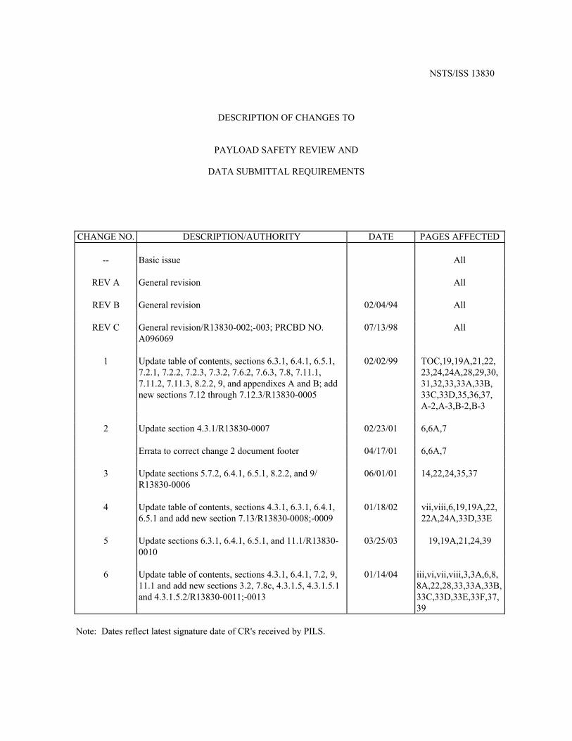
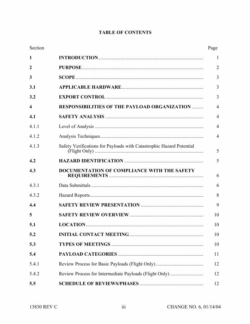
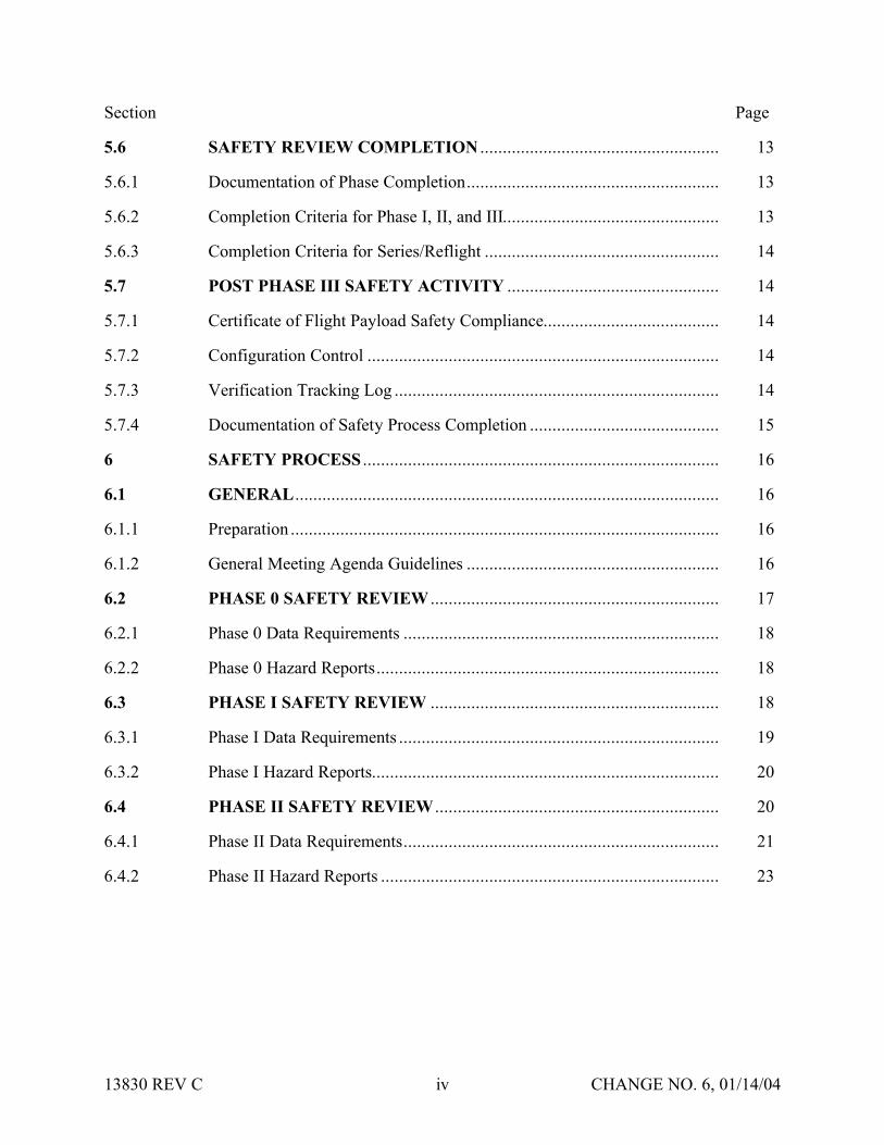
Section Page
56 SAFETY REVIEW COMPLETION 13
561 Documentation of Phase Completion 13
562 Completion Criteria for Phase I II and III 13
563 Completion Criteria for SeriesReflight 14
57 POST PHASE III SAFETY ACTIVITY 14
571 Certificate of Flight Payload Safety Compliance 14
572 Configuration Control 14
573 Verification Tracking Log 14
574 Documentation of Safety Process Completion 15
6 SAFETY PROCESS 16
61 GENERAL 16
611 Preparation 16
612 General Meeting Agenda Guidelines 16
62 PHASE 0 SAFETY REVIEW 17
621 Phase 0 Data Requirements 18
622 Phase 0 Hazard Reports 18
63 PHASE I SAFETY REVIEW 18
631 Phase I Data Requirements 19
632 Phase I Hazard Reports 20
64 PHASE II SAFETY REVIEW 20
641 Phase II Data Requirements 21
642 Phase II Hazard Reports 23
13830 REV C iv CHANGE NO 6 011404
Section Page
65 PHASE III SAFETY REVIEW 23
651 Phase III Data Requirements 23
652 Phase III Hazard Reports 25
653 Phase III Verification Tracking Log 26
7 SUPPORTING TECHNICAL DATA SUBMITTALS 27
71 STRUCTURES 27
711 Phase I 27
712 Phase II 27
713 Phase III 27
72 PRESSURIZED SYSTEMS (vessels lines fittings components) 28
721 Phase I 28
722 Phase II 28
723 Phase III 29
73 PYROTECHNIC DEVICES 29
731 Phase I 29
732 Phase II 30
733 Phase III 30
74 MATERIAL FLAMMABILITY TOXICITY AND COMPATIBILITY 30
741 Phase I 30
742 Phase II 30
743 Phase III 30
75 IONIZING RADIATION 31
751 Phase I 31
752 Phase II 31
13830 REV C v CHANGE NO 6 011404
Section Page
753 Phase III 31
76 NON-IONIZING RADIATION 31
761 Phase I 31
762 Phase II 31
763 Phase III 31
77 PAYLOAD COMMANDING 32
771 Phase I 32
772 Phase II 32
773 Phase III 32
78a ELECTRICAL (POWER BONDING AND GROUNDING)SUBSYSTEMS 32
78a1 Phase I 32
78a2 Phase II 32
78a3 Phase III 32
78b AVIONICS CONTROL 32
78b1 Phase I 32
78b2 Phase II 32
78b3 Phase III 33
78c COMPUTER SYSTEMS (Avionics) 33
78c1 Phase I 33
78c2 Phase II 33
78c3 Phase III 33
79 MECHANISMS IN CRITICAL APPLICATIONS 33A
791 Phase I 33A
792 Phase II 33A
793 Phase III 33A
13830 REV C vi CHANGE NO 6 011404
Section Page
710 SOLID ROCKET MOTORS 33A
7101 Phase I 33A
7102 Phase II 33B
7103 Phase III 33B
711 BATTERIES 33B
7111 Phase I 33B
7112 Phase II 33B
7113 Phase III 33C
712 FLUID PROPULSION SYSTEMS 33C
7121 Phase I 33C
7122 Phase II 33D
7123 Phase III 33E
713 SEALED CONTAINERS (STRUCTURES) 33E
7131 Phase I 33E
7132 Phase II 33F
7132 Phase III 33F
8 VARIATIONS OF THE SAFETY REVIEW PROCESS 34
81 VARIATIONS FOR INTEGRATED MULTIPAYLOAD CARGO COMPLEMENTS 34
82 VARIATIONS FOR ISS PAYLOADS 34
821 On-orbit Reconfigured Payloads 34
822 Payloads Returning to Earth 35
9 REFLOWN AND SERIES PAYLOAD HARDWARE 36
10 PAYLOAD SAFETY NONCOMPLIANCE REPORT 38
101 NCR SUBMITTAL 38
13830 REV C vii CHANGE NO 6 011404
Section Page
102 TYPES OF SAFETY NCRs 38
1021 Waivers 38
1022 Deviations 38
11 LIST OF FORMS 39
111 JSC FORMS 39
112 KSC FORMS 39
12 APPLICABLE DOCUMENTS 40
APPENDIX A DOCUMENT MATRIX A-1
APPENDIX B ACRONYM LIST B-1
13830 REV C viii CHANGE NO 6 011404
SECTION 1 INTRODUCTION
Implementation of the payload safety process is the joint responsibility of the Payload Organization (PO) the flight operator Lyndon B Johnson Space Center (JSC) and the launchlanding site operator John F Kennedy Space Center (KSC)
The International Space Station (ISS) and Space Shuttle Program (SSP) safety policies and requirements for ISS and Shuttle payloads are specified in the current version of NSTS 17007ldquoSafety Policy and Requirements for Payloads Using the Space Transportation Systemrdquo and the current version of the NSTS 17007 ISS Addendum ldquoSafety Policy and Requirements for Payloads Using the International Space Stationrdquo In addition unique ground safety policies and requirements are specified in the current version of 45 SPW HB S-100KHB 17007 ldquoSpace Shuttle Payload Ground Safety Handbookrdquo These documents require the PO to conduct asystematic safety analysis and to document and submit a Safety Data Package (SDP) in support of safety reviews to be conducted by the flight operator (JSC) and the launchlanding site operator (KSC)
National Aeronautics and Space Administration (NASA) Headquarters has assigned the responsibility to review submitted payload safety documentation to the Space Shuttle and Space Station Program Directors at JSC and the Director of Safety and Mission Assurance at KSC The JSC Payload Safety Review Panel (PSRP) will assess the payload design and flight operations the KSC Ground Safety Review Panel (GSRP) will assess the Ground Support Equipment (GSE) design and ground operations These two panels were formed to accomplishthe following
bull Assure that PO interpretation of the safety requirements is consistent with NASA payload safety policy
bull Conduct safety reviews as appropriate during the development of the payload associated GSE and related operations
bull Evaluate hazard analyses and Noncompliance Reports (NCRs) bull Negotiate the resolution of safety issues involving design and operation to ensure compliance
with all applicable safety requirements bull Assess payload design features that have been implemented for controlling identified hazards
and the verification approach that confirms intended system performance
13830 REV C 1 CHANGE NO 6 011404
SECTION 2 PURPOSE
The purpose of this document is to define the payload safety review process in order to assist the ShuttleISS POs in documenting compliance with the payload requirements documents specified in section 1 Specifically this document accomplishes the following
bull Defines the safety reviews necessary to comply with the system safety requirements that are applicable to payload design flight operations GSE design and ground operations for both ISS and Space Shuttle
bull Identifies the required content of the SDP bull Describes preparation for and conduct of the safety review bull Establishes the timeline for data submittal and establishes the depth of detail required for the
various submittals bull Explains safety review process variations bull Defines the payload seriesreflight review process
13830 REV C 2 CHANGE NO 6 011404
SECTION 3 SCOPE
Data submittal requirements included herein apply to hardware being submitted to both the PSRP and the GSRP unless specified otherwise This document outlines the minimum data submittal requirements the PSRP and the GSRP reserve the right to request additional data as deemed necessary to support safety documentation
The objective of the safety review process is to review the payload GSE and operations for adequate safety implementation The mission success and any scientific objectives of the payload are the responsibility of the PO and are beyond the scope of this document and process
This document does not establish design requirements
31 APPLICABLE HARDWARE
This document applies but is not limited to the following payload hardware that fliesoperates on the Space Shuttle andor ISS during any mission phase (prelaunch launch ascent on-orbit entry landing or postlanding)
bull New Payload Hardware bull Existing (reflown and series) Payload Hardware bull Hardware Associated with Developmental Test Objectives (DTOs) Detailed Supplemental
Objectives (DSOs) Risk Mitigation Experiments (RMEs) Space Medicine Program (SMP) and Human Exploration and Development of Space Technology Demonstrations (HTDs) Experiment Hardware
The document also applies but is not limited to the following payload-related hardware
bull Government-Furnished Equipment (GFE) bull Airborne Support Equipment (ASE) bull GSE
32 EXPORT CONTROL
The PSRP complies with the United States export control laws and regulations as established by the US Department of Commerce in the Export Administration Regulations (EAR) and the US Department of State in the International Traffic in Arms Regulations (ITAR) The PSRP also complies with the Space Shuttle Programrsquos export control policy in NSTS 07700 Volume V and the ISSPrsquos export control policy in SSP 50223
13830 REV C 3 CHANGE NO 6 011404
Export control factors significantly into two areas of the payload safety review process
bull Distribution of Payload Data
bull Conduct of Safety Reviews
The PSRP Executive Secretary serves as the primary exporter of payload data to the ISS International Partners (IPs) and other foreign persons in support of the payload safety review process Payload data includes safety data packages hazard reports safety review presentation materials and other payload related information Specific export control data submittalrequirements for payload organizations are listed in section 4315 of this document
The PSRP Executive Secretary takes special precautions when conducting safety reviews for payloads under export control restrictions These precautions may include restricting attendance limiting presentation materials posting signs or conducting the review in a secure facility
13830 REV C 3A CHANGE NO 6 011404
SECTION 4 RESPONSIBILITIES OF THE PAYLOAD ORGANIZATION
The PO is responsible for assuring the safety of its payload and for complying with the safety requirements contained in the technical requirements documents cited in section 1 To this end the PO must accomplish the following
bull Perform a Safety Analysis bull Identify Hazards bull Document Compliance with the Safety Requirements bull Present the Documentation to the PSRPGSRP
41 SAFETY ANALYSIS
To meet the requirements of the current version of NSTS 17007 and NSTS 17007 ISS Addendum paragraph 301 the PO shall perform a safety analysis of the payload and GSE The analysis shall consider hardware design verification testing and flightground operations The safety analysis shall begin during the payload concept phase and shall be refined and expanded as the design matures For situations in which payload hardware will be installed orreconfigured on-orbit or in which the payload will be on-orbit for an extended time safety analyses shall consider the necessity of on-orbit verificationreverification of hazard controls
411 Level of Analysis
In order to identify the hazards applicable to a payload the PO shall conduct safety analyses both at the system and subsystem levels Each system and subsystem shall be evaluated to determinethe applicability of each technical safety requirement
Selection of subsystem groupings varies and any convenient grouping may be used The following is a suggested list of subsystems biomedical caution and warning cryogenic electrical environmental control human factors hydraulics materials mechanical opticalpressure systems propulsion pyrotechnics radiation and structures
For hardware developed for or provided to the PO the PO shall
bull Obtain the appropriate safety data from the supplier or conduct an independent safety analysis
bull Conduct a safety analysis of the interfaces between the subject hardware and other elements
412 Analysis Techniques
Depending on the complexity of the payload the PO should use established analytical techniques (eg preliminary hazard sneak circuit fault tree operational hazard and failure modes and effects analyses) to obtain the data necessary to complete present and support payload hazard reports
13830 REV C 4 CHANGE NO 6 011404
413 Safety Verifications for Payloads with Catastrophic Hazard Potential (Flight Only)
The current version of NSTSISS 18798 specifies data requirements to document the verification program for payload systemssubsystems that have catastrophic hazard potential An excerpt from this document is included below for convenience
Table 4-1 - NSTSISS 18798
All payload systems having catastrophic hazard potential for the orbiter or crew as a result of operations in or near the orbiter must use hardware and procedures that have been subjected to a rigorous verification program Verification programs normally require testing to verify adequate performance margins under all environmentalconditions (qualification testing) as well as demonstrating intended system performance on flight hardware Comprehensive system-level testing on payload flight hardware supported by qualification test on protoflight or flight type hardware are the preferred verification methods It is essential that payload system performance be verified from the input stimuli to the end function
Safety-critical system performance that cannot be verified by test shall be verified by independent parties using dissimilar analysis techniques whenever possible Single party analytical efforts can be used to verify performance only when the methodology is widely accepted and conservative margins are applied to the results
The payload organization must focus its attention to all parts of the payload verification program and orbiter interface verification activities to assure that the sub-elements of the total verification program are integrated into a comprehensive system verification effort that confirms the intended system performance When the use of ground test equipment(apparatus) is required to replace flight hardware functions verification methods shall be developed by engineering personnel independent from those designing the flight systemTest requirements procedures and test apparatus shall be derived from intended functional requirements rather than from the design and all items must be maintained under strict configuration control The payload organization is responsible for developing and presenting sufficient data to the PSRP [GSRP] to substantiate that the test requirements procedures and test apparatus will provide an adequate simulation in substitution for the end function
42 HAZARD IDENTIFICATION
The primary objectives of the safety review process are to identify the potential hazards applicable to a payload including its flight GSE and ground operations and to assure that the hazard controls and verifications (including on-orbit verificationreverification of hazard controls where applicable) are adequate and in compliance with the safety requirements To assist the PO in accomplishing these objectives appropriate safety terminology has been defined in the current version of NSTS 17007
Although not exhaustive the following is a list of some previously identified flight hazard groups that have been used on hazard reports collision contamination corrosion electrical shock explosion fire injury and illness loss of orbiter entry capability and inability to egress
13830 REV C 5 CHANGE NO 6 011404
The following are basic hazard groups applicable to ground operations structural failure of support structures and handling equipment collision during handling inadvertent release ofcorrosive toxic flammable or cryogenic fluids loss of habitablebreathable atmosphere inadvertent activation of ordnance devices ignition of flammable atmospherematerial electrical shockburns personnel exposure to excessive levels of ionizing or nonionizing radiation use of hazardousincompatible GSE materials inadvertent deployment of appendages working under suspended loads and rupture of composite epoxy overwrapped pressure vessels
43 DOCUMENTATION OF COMPLIANCE WITH THE SAFETY REQUIREMENTS
The safety analysis results shall be documented in the SDP which includes applicable payload hazard report forms (JSC Form 542B and JSC Form 1230) and presented to both the JSC PSRPand the KSC GSRP as described in this document Guidelines for completing the flight hazardreport forms and preparing the SDPs are found in JSC 26943 ldquoGuidelines for the Preparation of Payload Flight Safety Data Packages and Hazard Reports for Payloads Using the Space Shuttlerdquo current issue
For SDP preparation the PO is responsible for using the current version of all applicable forms and safety documentation The PO may verify current formsdocuments by contacting theExecutive Secretary to the PSRP or the Chairman of the GSRP These forms are listed in section 11
431 Data Submittals
Although there will be some duplication of material contained in data submittals prepared for PSRP and GSRP reviews each package serves a different purpose and must stand alone
Data submittals which may include SDPs and other supporting information (eg action item responses) should identify the flight on which the payload is manifested (if known) and be formally submitted in English to the Executive Secretary PSRP or the Executive Secretariat GSRP Data should be formally transmitted under the signature of the Program Manager
Safety review meetings are scheduled to be held approximately 45 calendar days after receipt of an acceptable SDP (ie an SDP that satisfies all the requirements in this document)
The SDP will be made available to the PSRPGSRP members and various other NASAcontractor technical and administrative personnel who support the Panels For ISS payloads this may include International Partner representatives to the PSRP
Payload safety data must be submitted electronically via the Internet using the Payload Safety Data Management System (DMS) located at the following URL
httppsrpjscnasagov
The DMS System Administrator (tel 281-483-9078) can provide information on acceptable software applications electronic addresses detailed login instructions and system procedures POs may also access the DMS via a hyperlink at the top of the Payload Safety homepage located at the following URL
13830 REV C 6 CHANGE NO 6 011404
httpwwwsrqajscnasagovpce
POs must obtain approval from the PSRP Executive Secretary or Executive Secretariat GSRP to submit flight or ground safety data respectively by alternate means or to submit supplementary data in hard copy format Hard copy submittals must be single-sided and sequentially paginated from the cover sheet to the last page of the package
Once the SDP has been electronically submitted the PO must send the transmittal lettersdocument signature pages and signed original Hazard Reports (HRs) to the appropriate Panel contact
Executive Secretary PSRPNASA Lyndon B Johnson Space Center
Mail Code NC4 2101 NASA Road 1
Houston TX 77058-3696
Executive Secretariat GSRP NASA John B Kennedy Space Center
Mail Code UB-F3 Kennedy Space Center FL 32899-0001
13830 REV C 6A CHANGE NO 6 011404
4311 Submittal of Proprietary Data
If proprietary data are submitted in the SDP the transmittal letter must include the following statement
This payload safety data package contains proprietary data on the following pages [listthe appropriate page numbers] [Insert name of the payload organization] acknowledges awareness and acceptance of the GSRP and the PSRPrsquos policies and methods of processing proprietary data [Insert name of the payload organization] also will provideany additional protective measures it deems necessary over and above that provided by the panels during meetings
The transmittal letter and the first page of the SDP must identify the specific pages that contain proprietary information Insert the word ldquoPROPRIETARYrdquo at the top and bottom of each pagethat contains proprietary data The word ldquoPROPRIETARYrdquo shall be in all capital letters in alarge font size and style that is easily discernible from the rest of the text
In addition to the proper submittal of proprietary information the PO should be aware of the following while attending PSRPGSRP safety reviews Technical Interchange Meetings (TIMs) and action item closure meetings
bull PSRPGSRP meetings are not conducted in secure facilities Thus when it is necessary torecess meetings (eg lunch and breaks) the POs will be responsible for protecting any proprietary data distributed during the meeting (other than that logged and distributed byNASA as part of the SDP)
bull If any proprietary data are to be presented or discussed during the meeting prior to the meeting the PO will notify the PSRP Executive SecretaryGSRP Chairman who will then make arrangements to monitor attendance close the doors and post a sign noting that accessto the meeting is controlled
bull The PO will be responsible for retrieval and disposition of any proprietary material distributed at the meeting (other than that logged and distributed by NASA as part of the SDP) with the exception that two copies of proprietary material distributed by the PO at the meeting will be retained by the PSRPGSRP in a protected file
When the PSRPGSRP receives proprietary data included in the SDPs such data will be handledin a manner that will protect the interests of the PO These procedures include trackingdistributed materials protecting files and restricting reproduction In order to exercise reasonable care in protecting proprietary data in connection with the payload safety review process NASA will ensure that proprietary data are distributed only to persons who have a needto review such data in support of panel functions Furthermore distributed data that is returned to the PSRP Executive SecretaryGSRP Chairman after use will be destroyed via the NASAsecure disposal process
13830 REV C 7 CHANGE NO 6 011404
The protection of material marked ldquoPROPRIETARYrdquo creates an added burden on thePSRPGSRP review support system so the PO should mark only those items that are proprietary The PO should coordinate with the PSRP Executive SecretaryGSRP Chairman to explore such alternatives as providing the proprietary material in a separate package when it is a very small portion of the overall SDP If a separate proprietary briefing package (not containedin the SDP) is to be presented to the PSRPGSRP during the review the PO shall provide at least20 copies of such material for distribution at the review
If the PO discovers that some portion of the SDP marked ldquoPROPRIETARYrdquo is no longerconsidered such the PO must inform the PSRP Executive Secretary andor the GSRP Chairmanin writing
4312 Submittal of Copyrighted Data
Payload organizations are hereby informed that payload documentation submitted to NASA must be reproduced and distributed to the members of the PSRPGSRP and to associated technicalsupport personnel Accordingly copyrighted data shall not be included in the submitteddocumentation unless the PO 1) identifies such copyrighted data and 2) grants to theGovernment or acquires on behalf of the Government a license to reproduce and distribute the data to these necessary recipients
4313 Submittal of Translated Data
For all documents submitted by the PO to the PSRPGSRP that have been translated intoEnglish the English translation shall be the official document
4314 Submittal of Toxicological Data for SSP and ISS Payloads (Flight Only)
The ShuttleISS payload safety review process requires biomedical safety assessments of potentially hazardous materials such as chemicals microorganisms and radioisotopes In order for these assessments to be available for the safety reviews the JSC Toxicology Group requires POs to submit test sample data substantially in advance of the safety reviews See JSC 27472 ldquoRequirements for Submission of Test Sample-Materials Data for Shuttle Payload Safety Evaluationsrdquo current issue for the timeline and data requirements for these early submittals The PO must attach both the data submitted to JSC Toxicology Group and the JSC response (when available) to the applicable hazard report that is a part of the SDP Should toxicology submittals involve proprietary data see section 4311
4315 Submittal of Export Control Data (Flight Only)
The export control data submittal requirements in sections 43151 and 43152 apply to USpayload organizations only IP payload organizations are not required to provide the US export control classification of their safety data packages In the event that an IP SDP requires a USexport control classification NASA export control resources will be used to classify the SDP
13830 REV C 8 CHANGE NO 6 011404
43151 ISS Payloads
Distribution of ISS payload safety data packages to the ISS IPs is a standard part of the payload safety review process
The PO must identify the export control classification of the SDP payload data in its transmittal letter The first page of the SDP must also identify the export control classification of the data
The PSRP Executive Secretary will not distribute an SDP with an unknown export controlclassification to the IPs Safety reviews may be delayed or cancelled for ISS payloads with unresolved export control issues
The POrsquos safety review presentation materials must have the same export control classification as the SDP submitted for review or a less restrictive export control classification
43152 Shuttle Payloads
Distribution of Shuttle payload safety data packages to the ISS IPs is not a standard part of the payload safety review process
Shuttle payload safety data packages are not distributed to the IPs unless the PSRP identifies a specific need to do so If a need is identified the PSRP Executive Secretary will work with the PO and the SSPrsquos export control resources to obtain the export control classification of the SDP
The PO may include the export control classification of the SDP payload data in its transmittalletter and on the first page of the SDP if the classification is known prior to SDP submittal
432 Hazard Reports
The purpose of the hazard reports is to document the POrsquos safety assessment in a manner that reflects how the payload design demonstrates compliance with the safety requirements The hazard reports are used as a method to systematically assess compliance with the safety requirements
The flight SDP submittal must contain all flight hazard reports the ground SDP submittal mustcontain all ground hazard reports Each hazard report must be signed and dated by the payloadprogram manager prior to submittal Hazard reports shall be prepared on JSC Form 542B JSCForm 542B-1 or JSC Form 1230 (see section 11) or an equivalent form that contains all information required on the JSC forms Section 7 organized by area of design identifies minimum support data for flight hazard reports JSC 26943 contains guidelines for preparingpayload flight hazard reports
13830 REV C 8A CHANGE NO 6 011404
Following any technical discussion the PSRPGSRP Chairman will provide a disposition for each hazard report This disposition may take one of the following forms 1) approved aswritten 2) approved with modification 3) approved with an action to be performed by the PO andor PSRPGSRP and 4) not approved
The PO is responsible for retaining and maintaining the original hazard reports after approval
44 SAFETY REVIEW PRESENTATION
The PO should be prepared to present information submitted in the SDP to the appropriate safety panel during scheduled reviews (see sections 611 and 612) During reviews the PO shouldprovide briefing chart handouts sufficient for the number of people expected to attend the review
13830 REV C 9 CHANGE NO 6 011404
SECTION 5 SAFETY REVIEW OVERVIEW
51 LOCATION
Safety reviews for payload design and flight operations are usually conducted at JSC The safetyreviews for GSE design and ground operations will normally be conducted at KSC The PO shall coordinate the timing of the PSRP reviews with the PSRP Executive Secretary The PO shall coordinate the timing and location of the GSRP reviews with the GSRP Chairman
52 INITIAL CONTACT MEETING
The PO may receive initial contact safety briefings by the JSC and KSC safety representatives The JSC briefing normally held during the first integration meeting at JSC should be scheduledby contacting the Payload Integration Manager (PIM) at JSC For ISS payloads contact the ISSPIM The KSC briefing is usually held in conjunction with the first Ground Operations Working Group (GOWG) meeting which is scheduled through the Launch Site Support Manager Integration Manager (LSIM) at KSC
The briefing includes an overview of the technical and system safety requirements to be met by the PO plus instructions for conducting the safety reviews The PO should provide a schedule ofpayload milestones and request a phase 0 or phase I safety review when the payload design concept has been developed
53 TYPES OF MEETINGS
Safety reviews may take place in person via teleconference or by correspondence Review meetings may be formal or out-of-board as deemed appropriate by the Panel Chairman
bull Formal Meeting Formal meetings constitute a gathering of the safety review panel representatives of the PO and the appropriate supporting technical staff
bull Out-of-Board Meeting Out-of-board meetings do not require the full safety panel Attendees may include the Panel Chairman Safety representative(s) representatives of the PO and others necessary to address the issues that may be involved
bull Safety TIM The review panel andor associated technical staff may convene upon request in order to assist in interpreting safety requirements or to coordinate safety analysesissues prior to safety reviews Requests for flight safety TIMs should be coordinated with the PSRP Executive Secretary Requests for Ground Safety TIMs should be coordinated with the GSRP Chairman Material to be addressed during the TIM should be provided 14 calendardays prior to the TIM
bull Splinter Meetings Splinter meetings may be held concurrently with a safety review to discuss detailed technical concerns
13830 REV C 10 CHANGE NO 6 011404
54 PAYLOAD CATEGORIES
Traditional payload safety compliance assessment is accomplished using a phased safety review process (phases 0 I II III) that corresponds to the hardware conceptual preliminary and critical design review phases and verificationvalidation of the payload (see section 6) Successful completion of each safety phase is documented by SDPHR submittals to and approval by the PSRPGSRP
To streamline this process the PSRP has implemented procedures and data requirements to minimize formal PSRP review time for payloads with routine hazardsstandard controlsverifications This allows the PSRP to concentrate review time on payload systems withthe highest hazard potential ldquomust-workrdquo functions andor nonstandard controls and verification methods POs may document routine hazards and standard controls and verifications on the JSC Form 1230 ldquoFlight Payload Standardized Hazard Control Reportrdquo
Based on the phase I SDP new payloads are categorized by the PSRP into one of three categories of complexity (basic intermediate or complex) with respect to hazard potential as shown in Table 5-1 below The review process is then tailored to the complexity of the payload design and adequacy of documentation In addition the process permits all payloads to document standard hazards that have standard controls and verifications on JSC Form 1230 which may be approved by the PSRP without a formal PSRP meeting Details concerning basicand intermediate categories are contained in sections 541 and 542 respectively Complexpayloads use the review process detailed in section 6 Reflown and series payloads use thereview process outlined in section 9
Table 5-1 - PAYLOAD CATEGORIES
PayloadCategory
Defined Hazards
Basic The only hazards identified are ldquostandardrdquo as specified on the JSC Form 1230 The appropriate hazard controls are found on JSC Form1230
Intermediate 1) The payload has ldquouniquerdquo hazards (ie hazards not found on the JSC Form 1230) but has controls and verification methods that have been historically accepted by the PSRPOR
2) The payload has ldquostandardrdquo hazards (ie hazards identified on the JSC Form 1230) but uses controls and verification methods other than those identified on the JSC Form 1230
Complex The payload has unique hazards with hazard controls that are
a Active ldquomust workrdquo functions such as electromechanical or pyrotechnic separation systems or actuatorsmechanisms providing structural load paths
OR b Nonstandard or have nonstandard verification methods that
depart from historically accepted techniquesOR c Operationally complex requiring flight or ground personnel
intervention to assist in controlling the hazard
13830 REV C 11 CHANGE NO 6 011404
If after a payload category has been assigned the PO a) identifies previously undefined hazards or b) implements design changes that may create new hazards the PO must submit a revisedSDP which may result in a reclassification of the payload category
541 Review Process for Basic Payloads (Flight Only)
Basic payloads (see Table 5-1 above) have a very low level of complexity which may allow the payload to complete the safety process out of board However the PO will submit an SDP that will document the applicable hazards controls and verifications Submittal will follow the standard procedure detailed in section 431 and approval may be obtained without a meeting The following data are required for the simplified SDP for hardware design and flight operations
bull Brief description of the hardware design and flight operations with schematics and block diagrams as appropriate
bull Summary of the safety analysis results that documents compliance with the design verification and applicable on-orbit verificationreverification requirements for the identified standard hazards
bull Documentation of all applicable hazards controls and verifications on hazard report(s) (eg JSC Form 1230Form 542)
bull Certificate of Payload Safety Compliance (JSC Form 1114A) signed by the ProgramManager
542 Review Process for Intermediate Payloads (Flight Only)
In addition to the standard hazards found in Basic payloads the Intermediate payload has unique hazards that have standard controls and verification methods (including applicable on-orbit verificationsreverifications) that have been historically accepted by the PSRP Intermediate category payloads should require one or two reviews of the unique hazards but the basic hazards may be addressed on a Form 1230 and approved out of board The PSRP will determine the need for a second review for unique hazards at the completion of the first review The determination will be based primarily upon the completeness and quality of the unique hazard reports Requirements for SDP submittal are the same as those stated in section 431
55 SCHEDULE OF REVIEWSPHASES
The schedule for formal phase 0 I and II payload safety reviews generally relates to the payload development schedule Phase 0 is held during the concept phase or at the start of payload design Phase I is near the Preliminary Design Review (PDR) phase II is near the Critical Design Review (CDR) The PO should set the review schedule to obtain maximum benefit to payloaddevelopment based on the results of the safety reviews
ISS payloads may include multiple major systems or components each working to a uniqueschedule These may be individually baselined and categorized (see section 54) which allows them to progress through the payload safety process in accordance with their own schedule (see section 82)
13830 REV C 12 CHANGE NO 6 011404
Phase III is associated with completion of payload safety verifications andor the start of ground processing When establishing a timeline for phase III the PO should allow enough time to closepotential issues that may result from a phase III review The timing and completion of the phase III review and safety certification are critical to the launch schedule The flight and ground phaseIII completion requirements restated below are in the current version of NSTS 17007 and NSTS 17007 ISS Addendum and apply to all payloads
The JSC and KSC Phase III safety review and ground safety certification must be completed 30 days prior to delivery of the payload ASE and GSE to the launch sitehellip
If any verification items remain open on the flight hazard reports the PO must provide rationale to support the safety of starting ground processing with these items open The rationale is to be submitted to both the PSRP and GSRP The PSRP will review the rationale and provideconcurrence to the GSRP
To schedule KSC Ground safety reviews contact the GSRP Chairman to schedule JSC Flight safety reviews contact the PSRP Executive Secretary (see section 431)
56 SAFETY REVIEW COMPLETION
561 Documentation of Phase Completion
During a formal meeting the Panel Chairman will make an official announcement that the safety phase is complete or incomplete (open) This announcement will be recorded and distributed bythe PSRPGSRP in the official meeting minutes Incomplete phases are usually attributable to overdueopen action items or unsigned (open) hazard reports The PSRPGSRP will issue officialcorrespondence to document closure of open action itemssignature of open hazard reports thatoccurs after the phase review The correspondence that closes the last open action itemhazardreport for that phase will include a statement that the safety phase is considered complete
For out-of-board reviews safety review process completion will be documented by formal correspondence
562 Completion Criteria for Phase I II and III
Successful completion of phase I and II reviews is accomplished by obtaining approval (Panel Chairmanrsquos signature) of hazard reports at the appropriate phase level and closure of applicable phase III action items
After submission of all required data the criteria for successful completion of the safety review process at the phase III level for both flight and ground reviews are as follows
bull All payload hazard reports are signed by the payload Program Manager and the Panel Chairman at the phase III level
bull All NCRs are approved bull Safety review action items are formally closed in the safety review meeting minutes or
documented closed in separate correspondence bull A signed Certificate of Ground Payload Safety Compliance provided to the GSRP (for phase
III ground safety)
13830 REV C 13 CHANGE NO 6 011404
Approval of the phase III safety data by the PSRP and GSRP is with the understanding that the data represent the actual design and operations of the payload Should safety issues arise after the safety process is complete the safety panels reserve the right to request additional data deemed necessary to reassess the payload
563 Completion Criteria for SeriesReflight
The criteria for successful completion of a series or reflight safety review is that all data required by section 9 Reflown and Series Payload Hardware have been submitted and approved
57 POST PHASE III SAFETY ACTIVITY
571 Certificate of Flight Payload Safety Compliance
The PO must present a signed Certificate of flight Payload Safety Compliance to the PSRP Executive Secretary no later than 10 days prior to the Flight Readiness Review (FRR)
572 Configuration Control
When changes to the design configuration or operations of the payload are required subsequent to phase III the PO shall assess those changes for possible safety implications including the effect on all interfaces The assessment shall be forwarded to the PSRPGSRP for review andapproval If the change has ground safety implications it must be reviewed with the KSC panel prior to proceeding with ground processing New or revised hazard reports and support datashall be prepared where applicable and submitted for approval as indicated in section 431 The need for delta phase III safety reviews will be determined by the PSRPGSRP Chairman Satisfactory completion of these activities is mandatory prior to the start of affected ground activities or launch
Any test failures anomalies or accidents involving payload flight hardware or software that occurs between the completion of phase III and launch must be promptly reported to the PSRPGSRP Safety impacts if any should be identified
573 Verification Tracking Log
Open verification items must be tracked on a flight or ground safety Verification Tracking Log (VTL) (see section 11)
bull Flight Safety From Phase III until L-60 days the PO shall update and provide the VTL to the PSRP Executive Secretary once a month From L-60 days until launch the PO shall provide a weekly update to the VTL All VTL open items must be closed no later than 4PM Central time on the last business day prior to launch Items that cannot be closed at this time will require the transmission of a facsimile closing the open VTL items to the Mission Evaluation Room (MER) at NASA JSC no later than L-6 hours Contact the PSRP Executive Secretary for MER delivery instructions
bull Ground Safety The initial submittal of the ground safety VTL is required with the phase III ground SDP Following the completion of the phase III review the ground safety VTL shall be updated monthly prior to hardware arrival at KSC If there are open flight verifications
13830 REV C 14 CHANGE NO 6 011404
that are constraints to ground processing the PO must also include those items of the flight VTL After the delivery of the payload ASE or GSE to the launch site the safety VTL(s) shall be updated at least weekly More frequent updates to the safety VTL(s) may be required if the open items must be closed to allow work to continue
574 Documentation of Safety Process Completion
Final flight safety approval is documented by the PSRP Chairmanrsquos signature on the Certificateof Flight Readiness (CoFR) for the planned flight
Final ground safety approval is documented by a letter from the KSC Director Safety Assurance to the KSC Director Customer Service Space Station and Shuttle Payloads Processing statingthat the Ground Safety Review Process has been completed and the payload may begin ground processing
13830 REV C 15 CHANGE NO 6 011404
SECTION 6 SAFETY PROCESS
61 GENERAL
611 Preparation
In preparation for a phase safety review the PO will submit an SDP as indicated in section 431 If phase reviews are combined (eg a phase III review) the SDP shall include the datarequirements that apply to all the appropriate phases The depth and number of the plannedreviews are dependent on the complexity technical maturity and hazard potential of the payload and may be modified by the Panel Chairman in conjunction with the PO
The PO should provide sufficient technical support personnel to answer questions posed by the PSRPGSRP in support of the agenda items
Listed below are general agenda topics for safety review meetings These insure that the safety review meetings proceed smoothly and contain the necessary information to facilitate the review
612 General Meeting Agenda Guidelines
The PO should coordinate all meeting agenda with the PSRP Executive Secretary or the GSRP Chairman prior to the safety review meeting and provide the final agenda in advance The fundamental elements of all Safety Review Meeting Agenda are as follows
a Introduction of the Meeting and Participants by the JSC Safety Reliability and Quality Assurance (SRampQA) Payload Safety Engineer (PSE)
b Opening Remarks by Chairman and the Payload Program Manager
c Discussion of Pre-Review Activity Led by the PSE
d Program-level Overview (including areas of responsibility)
e Program Milestone Schedule Provide the Program Milestone Schedule includingbut not limited to
(1) design stages and reviews
(2) hardwaresoftware build status
(3) testing and verification activities
(4) delivery integration and launch activities and
(5) safety review dates
f Mission Objectives including overview of mission objectives and general criteria for a successful mission
13830 REV C 16 CHANGE NO 6 011404
g SystemSubsystem Technical Presentation Overview including enough information to allow the PSRPGSRP to gain a general technical understanding of the systemsinvolved in the payload operations Highlight any design changes since the previous safety reviews
h Operations Overview describing planned operations and known contingencies Plan to discuss detailed operations that relate to payload safety in conjunction with the appropriate hazard report presentation Highlight any operations changes made tothe operations that impact the safety of the payload since the previous review
i Safety Assessment Summary including safety assessments performed to identify hazards any failures or anomalies that occurred after development testing and the corrective actions Present responses to agreements and formal action items including a summary of open action items and associated plans for closure Provide sufficient information to demonstrate that a comprehensive hazard analysis has been performed Provide an overview of hazards and how they relate to the hazard reports and discuss safety-related items that are not reflected in the hazard reports
j Phase-specific Topics Additional phase-specific topics for the agenda should be drawn from the data that are required to be included in the SDP for that phase (see sections 621 631 641 and 651) If not included as one of the general agendatopics these data should be addressed as separate agenda items
k Hazard Report Presentation Unless otherwise agreed to by the PSRPGSRPpresent all hazard reports in full associated noncompliancereportswaiversdeviations previously assigned action itemsagreements that involved modification of hazard reports and associated action itemagreement responses
l Action Item Review Both the PO and the PSRPGSRP will review and agree toactions and due dates assigned during the course of the safety review to ensure that there are no misunderstandings These action items will be printed and signed during the review
m Closing Comments Payload Program Manager and Panel
62 PHASE 0 SAFETY REVIEW
The optional phase 0 safety review is provided as a service to the PO The objectives of the meeting are to
bull Assist the PO in identifying hazards hazard causes and applicable safety requirements early in the development of the payload
bull Adequately describe the hazard potentialbull Answer questions regarding the interpretation of the safety requirements or the
implementation procedures of this documentbull Provide guidance to the PO for preparing the safety data required for subsequent safety
reviews
13830 REV C 17 CHANGE NO 6 011404
621 Phase 0 Data Requirements
The following data are required for the phase 0 SDP and must be submitted as stated in paragraph 431
a For payload design and flight operations
(1) Conceptual payload description (including subsystems) and missionscenario
(2) Description of safety-critical subsystems and their operations
(3) Flight hazard reports (JSC Form 542BForm 1230)
b For GSE design and ground operations
(1) Conceptual payload description and brief mission scenario
(2) Conceptual GSE description and operations and description of payload design that is safety critical during ground operations
(3) Ground operations scenario
(4) Ground hazard reports (JSC Form 542B)
The description of the payload and its operation must be of sufficient detail to permit identification of all subsystems that may create hazards Emphasis should be given to thosesubsystems that store transfer or release energy The descriptions of the safety-critical subsystems must be of sufficient detail to identify the hazards in terms consistent with the conceptual design In addition the PO shall address tentative plans for any flight operation (eg extravehicular activity reverification of hazard controls) or ground operation that would require personnel certification to perform hazardous procedures
622 Phase 0 Hazard Reports
The purpose of a phase 0 hazard report is to document and scope the specific hazards identified It is intended to be a working document for discussion and critique at the phase 0 safety review and will not require signatures A hazard report must be prepared for each unique hazardidentified in the safety analysis The hazards contained on the phase 0 hazard report must reflect the payload conceptual design and operations existing at the time of the phase 0 review For phase 0 the PO may identify hazard controls verification methods or status of verifications
63 PHASE I SAFETY REVIEW
The purpose of the phase I safety review is to obtain PSRPGSRP approval of the updated safety analysis that reflects the preliminary design and operations scenario of the payload At this pointthe PO shall present a refined safety analysis that identifies all hazards and hazard causes inherent in the preliminary design evaluates all hazards for means of eliminating reducing or controlling the risk and establishes preliminary safety verification and on-orbit verificationreverification methods The PO shall provide a preliminary identification of the payload interfaces and of the hazards presented by these interfaces
13830 REV C 18 CHANGE NO 6 011404
631 Phase I Data Requirements
The following data are required for the phase I SDP and must be submitted as stated in paragraph 431
a For payload design and flight operations
(1) Updated payload description (including subsystems) and mission scenario
(2) Updated descriptions of safety-critical subsystems and their operations including schematics and block diagrams with safety features inhibits and controls identified Identify any safety-critical subsystems that are computer controlled and identify the functional architecture associated with that computer control
(3) Updated and additional flight hazard reports (eg JSC Form 542BJSC Form 1230) including appropriate support data (see section 7) For payloads thathave catastrophic hazard potential document the verification programoutlined in NSTSISS 18798
(4) A summary list (in the payload description) of orbiter- andor ISS program-provided critical services and an explanation (in the appropriate hazard reports) of the orbiter andor ISS services used to control andor monitorpayload hazards (NSTS 17007 and NSTS 17007 ISS Addendum current version)
(5) For ISS payloads a presentation of the Fire Detection and Suppression (FDS) implementation approach For sub-rack payloads the PO shall address the integrated system approach (using sub-rack services andor ISS services) to fully define the FDS implementation strategy In addition submit JSC Form 1428 to document methods and verifications used to detect and suppress a fire event for each payload volume
(6) Discussion of design features supporting verificationreverification of hazard controls on-orbit and associated constraints
(7) A tabulated list of tentative toxic materials and support data per JSC 27472(see section 4314)
(8) A list of all battery types their uses manufacturer and applications
(9) A preliminary description of all pyrotechnic devices and their functions
(10) Preliminary on-orbit maintenance safety assessment as outlined in NSTSISS 18798
b For GSE design and ground operations
(1) Updated payload description and brief mission scenario
13830 REV C 19 CHANGE NO 6 011404
(2) Updated descriptions of GSE payload subsystems that present a potential hazard during ground processing and their ground operations Schematics and block diagrams with safety features and inhibits identified should be included Design data for hazardous systems (pressure lifting etc) shall be summarized in a matrix Contact the GSRP Chairman for sample formats
(3) Updated ground operations scenario including postflight ground operationsat the primary alternate and contingency landing site The scenario should highlight unique payload requirements at the launch pad such as continuous power through a T-0 umbilical
13830 REV C 19A CHANGE NO 6 011404
(4) Updated ground hazard reports (JSC Form 542B) including appropriatesupport data
(5) Ordnance data required by the current version of KHB 17007 Appendix D
(6) Estimated KSC on-dock arrival date
632 Phase I Hazard Reports
The PO shall prepare phase I hazard reports for each hazard identified as a result of the safety analysis for the preliminary design and operations scenario of the payload Hazard reports shallbe added to or deleted from those agreed to during phase 0 to reflect the updated safety analysis Rationale for deleting a hazard agreed upon at phase 0 shall be presented during the phase I review
For phase I the PO shall identify hazard controls for each hazard cause identified at phase 0 A direct correlation between each hazard cause and the corresponding hazard control(s) must be clearly shown on the report Sufficient supporting information detailing each hazard control must be provided
Verifications should include the types of tests analyses inspections or procedures to be used to verify each hazard control including all orbiter- or ISS-provided services or interfaces both prelaunch and on-orbit A direct correlation between each verification method and the corresponding hazard control must be clearly shown on the report Each verification item should be independent and have a designator that allows for individual tracking of verification status
Manufacturingassembly proceduresprocesses that are critical in controlling hazards that cannot or will not be verified by subsequent inspection or test must be verified during the manufacturingassembly process An independent verifier as specified by the PO shall attest toproper completion of the procedureprocess Critical proceduresprocesses which require special monitored verification (Mandatory Inspection Points [MIPs]) shall be identified in preliminary fashion (NSTS 17007 and NSTS 17007 ISS Addendum current version)
If available the PO should provide a tentative schedule for completion of each verification taskand correlate with the integration schedule
64 PHASE II SAFETY REVIEW
The purpose of the phase II safety review is to obtain panel approval of the updated SDP that reflects the CDR-level design and operations scenario of the payload The phase II safety analysis identifies all hazards and hazard causes defines and documents implementation of a means for eliminating reducing or controlling the risks and documents finalized specific safety verification and on-orbit verificationreverification methods (test plans analysis and inspection requirements etc) Payload interfaces mission and ground operations procedures and timelines that were not addressed during the phase I safety review shall be assessed for safety hazards The payload interfaces to be assessed shall include those between the Shuttle andor ISS and the payload and among the various components that make up the payload (the spacecraft upper stages space platforms pallets experiments ASE ancillary flight equipment GSE KSC Facilities GFE etc) Newly identified hazards shall be documented in additional hazard reports For this review the PO should provide the estimated KSC on-dock arrival date
13830 REV C 20 CHANGE NO 6 011404
641 Phase II Data Requirements
The following data are required from the PO for phase II and must be submitted as stated in paragraph 431
a For payload design and flight operations
(1) Updated payload description (including subsystems) and mission scenario
(2) Updated descriptions of safety-critical subsystems and their operations including schematics and block diagrams with safety features and inhibits identified Provide electrical schematics that clearly identify the requirednumber of independent inhibits controls and monitoring provisions Present a summary of the test and analytical efforts required to verify the intended performance of all safety-critical hardware For a computer-based control system that is used to prevent criticalcatastrophic hazards provide the following datadescriptions bull Functional architecture bull Expected interactions bull Results of unexpected interactions bull Protections for common cause failures bull Development process for databases hardware software and
hardwaresoftware (3) Updated and additional flight hazard reports (eg JSC Form 542BJSC
Form 1230) including appropriate support data (see section 7) For payloads that have catastrophic hazard potential document the verification program outlined in NSTSISS 18798
(4) Updated summary list and explanation of orbiter- andor ISS-provided critical services
(5) For ISS payloads an update of the FDS implementation approach Include information on use of forced air flow wire derating circuit protection materials usage parameter monitoring (fan speeds temperatures currentetc) and responses to an out-of-limit condition and suppression approach For sub-rack payloads the PO shall address the integrated system approach (using sub-rack services andor ISS services) to fully define the FDS implementation strategy Updated JSC Form 1428 to reflect specific test (or analysis) procedures to be used along with the schedule for completion of FDS verification tests analyses or inspections
13830 REV C 21 CHANGE NO 6 011404
(6) Verification methods associated with hazard controls that require on-orbit verification andor reverification and the applicable approach (include rationale constraints and detailed methodology)
(7) An updated tabulated list of planned toxic materials and support data per JSC27472 (see section 4314) Updates should include changes in testmaterials changes in test conditions and any alternate test materials
(8) Updated list of all battery types their uses manufacturer and applications
(9) A list of all pyrotechnic devices their functions chemical composition critical components inspection plan verification plan and aging degradation evaluation plan
(10) List of hazard controls that require crew procedures andor training
(11) A record of test failures anomalies and accidents involving qualification or potential flight hardware Include a safety assessment for items which may affect safety
(12) The status of all action items assigned to the PO during phase I
(13) Detailed on-orbit maintenance safety assessment as outlined in NSTSISS 18798 Identify maintenance activities safe access areas and reverification of safety critical features
b For GSE design and ground operations
(1) Updated payload description and brief mission scenario
(2) Updated descriptions and matrices of the GSE the payload subsystems that present a potential hazard during ground processing and their ground operations Include updated schematics and block diagrams with safety features and inhibits identified Electrical schematics must show all payloadGSE grounding
(3) Updated ground operations scenario including postflight ground operations at the primary alternate and contingency landing sites
(4) Updated and additional ground hazard reports (JSC Form 542B) includingappropriate support data
(5) Updated ordnance data required by the current version of KHB 17007 Appendix D
(6) Updated KSC on-dock delivery date
(7) Specific engineering drawings and stress analyses of subsystems whenrequested by the GSRP Chairman
(8) A list of safety-related failures and mishaps that have occurred
13830 REV C 22 CHANGE NO 6 011404
(9) The status of all action items assigned to the PO during phase I
(10) A list of technical operating procedures that will be used at KSC with apreliminary designation as to which ones are considered hazardous
13830 REV C 22A CHANGE NO 6 011404
642 Phase II Hazard Reports
The PO shall prepare the phase II hazard reports by revising the phase I hazard reports to reflectthe completed payload design and flightground operating procedures If the payload designchanges from phase I to phase II so that a phase I hazard report may be deleted present a brief statement of rationale for deleting the report in the phase II SDP The GSRPPSRP willdisposition the hazard reports
Address all critical proceduresprocesses including the plan for verification Verifications shall refer to specific test (or analysis) procedures and summarize passfail criteria to be used Specifythe schedule for the completion of each specific verification test analysis or inspection
65 PHASE III SAFETY REVIEW
The purpose of the phase III safety review is to obtain PSRPGSRP approval of the SDP and safety compliance data that reflects the safety verification findings The focus of this review is to assess safety verification testing and analysis results If verifications critical for establishing the acceptability of the fundamental design of the payload for safety are not completed prior to the phase III review then subsequent reviews may be required prior to hazard report approval All verifications that are open at the time of the phase III SDP submittal must be included on the safety VTL Items listed on the VTL should be planned open work items such as groundprocessing at KSC
651 Phase III Data Requirements
The following data are required for the phase III SDP and must be submitted as stated in paragraph 431
a For payload design and flight operations
(1) Final as-built payload description (including subsystems) and mission scenario
(2) Updated descriptions that define the final configuration of the safety-critical subsystems and their operations including schematics and block diagramswith the as-built payload safety features and independent inhibits controls and monitoring provisions identified Address applicable features andconstraints relating to on-orbit verificationreverification of hazard controls
For a computer-based control system that is used to prevent criticalcatastrophic hazards provide verifications for the following bull Functional architecture bull Expected interactions bull Results of unexpected interactions bull Protections for common cause failures bull Flight article databases hardware software and hardwaresoftware
operate as designed
13830 REV C 23 CHANGE NO 6 011404
(3) Updated (and additional if required) flight hazard reports including support data that reflect the final configuration of the as-built payload and planned use For payloads that have catastrophic hazard potential document theverification program outlined in NSTSISS 18798
(4) Final summary list and explanation of orbiter- andor ISS-provided critical services
(5) For ISS payloads a finalized FDS implementation approach Include information on use of forced air flow wire derating circuit protectionmaterials usage parameter monitoring (fan speeds temperatures currentetc) and responses to an out-of-limit condition For sub-rack payloads the PO shall address the final integrated system approach (using sub-rack services andor ISS services) to fully define the FDS implementation strategy Final JSC Form 1428 to summarize the results of the completedtests analyses andor inspections and refer to particular test reports by document number title and date
(6) Updated (and additional if required) verification methods associated with hazard controls that require on-orbit verification andor reverification and the applicable approach (include rationale constraints and detailed methodology)
(7) A final tabulated list of toxic materials and support data per JSC 27472 (see section 4314) including additions and changes in test materials changes in test conditions and any alternate test materials
(8) A final list of all battery types their uses manufacturer and applications
(9) A final list of all pyrotechnic devices installed or to be installed on the payload The list will identify for each cartridge the function to be performed the part number the lot number and the serial number
(10) Updated list of hazard controls that require crew procedures and or training
(11) An updated record of test failures anomalies and accidents involving qualification or potential flight hadware or baselined flight software if the software is used for hazard control Include a safety assessment for items which may affect safety
(12) The status of all action items assigned to the PO through phase II
(13) Payload Flight Safety VTL (JSC Form 764)
13830 REV C 24 CHANGE NO 6 011404
(14) Identification of flight safety noncompliances Flight safety NCRs must be approved as either a waiver or a deviation before the phase III safety review can be completed A signed copy of each approved safety waiver andor deviation shall be included in the phase III SDP attached to the appropriate hazard report
(15) Finalupdated on-orbit maintenance safety assessment as outlined in NSTSISS 18798
b For GSE design and ground operations
(1) Final as-built payload description and brief mission scenario
(2) Updated descriptions and matrices defining the final configuration of the GSE the payload subsystems that are potentially hazardous during ground processing and their ground operations Include updated schematics andblock diagrams with the as-built safety features and inhibits identified
(3) Updated and finalized ground operations scenario including postflight ground operations at the primary alternate and contingency landing sites
(4) Updated and additional ground hazard reports including support data thatreflect the final configuration of the as-built GSE and planned payloadGSE use
13830 REV C 24A CHANGE NO 6 011404
(5) Updated and finalized ordnance data required by the current version of KHB 17007 Appendix D
(6) Updated and finalized KSC on-dock delivery date
(7) Specific engineering drawings and stress analyses of subsystems whenrequested by the GSRP Chairman
(8) A summary and safety assessment of all safety-related failures and accidents applicable to payload processing test and checkout Identify impact to theSpace Shuttle other payloads and facilities
(9) The status of all action items assigned to the PO through phase II
(10) Finalized list of technical operating procedures that will be used at KSC withthe hazardous procedures clearly identified The list shall also state the proposed first use of the procedure at KSC
(11) Verification that each payload flight system pressure vessel has a pressure vessel logbook that shows pressurization history fluid exposure and otherapplicable data This verification should account for the planned testing atKSC
(12) Payload Ground Safety VTL if required
(13) Certificate of Payload Safety Compliance (JSC Form 1114A) signed by the PO program manager for GSE design and ground operations
(14) Procedural hazard control matrix that identifies hazard control criteria within the associated work-authorization documents for all procedural hazards Contact GSRP Chairman for format
(15) Identification of ground safety noncompliances Ground safetynoncompliances must be approved as either a waiver or a deviation before the phase III safety review can be completed A signed copy of eachapproved waiverdeviation shall be included in the phase III SDP (seesection 10)
652 Phase III Hazard Reports
The phase III hazard reports shall (1) reflect the final payload design and operations and (2) document the status and results of all completed verification work If the payload design ischanged from phase II to phase III so that a phase II hazard report may be deleted provide in thephase III SDP a brief statement of rationale for deleting the report
The phase III hazard reports shall reflect the as-built design and operations of the payload Byphase III all safety analysis efforts should be completed Verifications completed by phase III shall be indicated as such on the hazard report This information shall summarize the results of the completed tests analyses andor inspections and refer to particular test reports by document number title and date
13830 REV C 25 CHANGE NO 6 011404
For those hazards controlled by the design-for-minimum-risk approach (per the current version of NSTS 17007 paragraph 2002) in addition to data provided for phases I and II the PO must provide additional data listed in section 7 of this document
For payload systems having catastrophic hazard potential for the vehicle or crew as a result of operations in or near the vehicle see paragraph 413
653 Verification Tracking Log
All flight safety verifications that are still incomplete at Phase III must be ldquoclosedrdquo on the hazard report and transferred to the flight safety VTL for further tracking This log will allowthe PSRP Chairman to sign the hazard reports indicating completion of the safety analysis but with the understanding that approval for flight will be withheld until all flight verification activity is completed
Similarly all open ground verifications must be listed on the ground safety VTL This log willallow the GSRP Chairman to sign the hazard reports indicating completion of the ground safety analysis Open ground verifications and open flight verifications that have been identified as a constraint against payload processing must be closed before the applicable ground operation canbe performed
13830 REV C 26 CHANGE NO 6 011404
SECTION 7 SUPPORTING TECHNICAL DATA SUBMITTALS
The information in this section applies to flight safety only except for the data identified in sections 75 and 76 which applies to both flight and ground safety
To further define the general data requirements in section 6 this section addresses SDP data submittals related to various technical disciplines to support hazard reports Hazard reports (JSCForm 542 and Form 1230) must be supported by the minimum set of data as outlined below Each such hazard report shall clearly identify the supporting data This supporting data shall besubmitted in one of the following manners a) attached to the hazard report b) as part of the SDP or c) submitted to the PSRP Executive SecretaryGSRP Chairman This official submittal path is not intended to preclude direct technical coordination between the PO and the appropriateJSCKSC technical disciplines
Technical areas of design such as structures pressure vessels and pressurized lines fittings and components are typically Design-For-Minimum-Risk (DFMR) areas of design The data submittal requirements in sections 71 and 72 are the minimum DFMR requirements for those particular design areas The remainder of section 7 contains the minimum data submittals required by the PSRP for either DFMR or failure tolerant designs
71 STRUCTURES
711 Phase I
Proposed Structural Verification Plan in accordance with NSTS 14046 ldquoPayload Verification Requirementsrdquo andor SSP 52005 ldquoISS Payload Flight Equipment Requirements and Guidelinesfor Safety Critical Structuresrdquo
Fracture Control Plan
Methodology for assurance of fastener integrity
712 Phase II
Final structural verification plan including 1) summary of design loads derivation leading to critical load cases and 2) math model verification plan
Fracture control status (including parts categorization)
Identification of Material Usage Agreements (MUAs) on structural materials the failure of which would cause a hazard (including but not limited to stress corrosion hydrogenembrittlement and materials compatibility)
713 Phase III
Summary of verification testsanalysesinspections results
Fracture control summary report
Newapproved MUAs as defined in phase II
Documentation of compliance with fastener integrity program
13830 REV C 27 CHANGE NO 6 011404
72 PRESSURIZED SYSTEMS (vessels lines fittings components)
721 Phase I
Preliminary pressurized system schematic and operating parameters (eg temperature pressure and other environmental conditions)
Preliminary summary of the derivation of system MDP(s) per NSTS 17007 and NSTS 17007 ISS Addendum
Preliminary list of all system working fluids their complete chemical composition amounts potential hazards (eg flammability explosion corrosion toxicity) and hazard category (eg catastrophic critical nonhazard)
Summary of pressure vessel(s) design and qualification approach
Damage control plan and stress rupture life assessment (COPVs only)
Fracture control plan
Proposed pressurized system(s) verification approach for controls to ensure pressure integrity
For fluids whose leakage is hazardous also include
Proposed pressurized system(s) verification approach including controls to prevent leakage (eg levels of containment Design for DFMR) For the DFMR approach to protect against leakage that may cause a catastrophic hazard include 1) identification of mechanical fitting and leakage certification approach for wetted areas Consider all environments where leakage is hazardous(eg in the Shuttle payload bay) and 2) preliminary identification of fusion and bi-metallic joints within the system
722 Phase II
Complete and updated pressurized system schematic(s) and operating parameters addressing allpressurized hardware
Complete summary of the derivation of system MDP(s) per NSTS 17007 and NSTS 17007 ISS Addendum Complete table of pressurized system hardware MDP(s) proof pressure ultimate pressure resulting proof and ultimate safety factors and method of determining the safety factors (eg test analysis vendor data)
Updated list of all system working fluids their complete chemical composition amounts identified hazards and hazard category
Status on pressure vessel(s) design and qualification
Fracture control status
Identification of MUAs on pressurized system materials the failure of which would cause a hazard (including but not limited to stress corrosion hydrogen embrittlement and materials compatibility [including working and cleaning fluids])
13830 REV C 28 CHANGE NO 6 011404
Final pressurized system(s) verification approach for controls to ensure pressure integrity including a summary of qualification and acceptance test plans and analysesFor fluids whose leakage is hazardous also include
Final pressurized system(s) verification approach including controls to prevent leakage (eg levels of containment DFMR) Include a summary of qualification and acceptance test plans and analyses For the DFMR approach to protect against leakage that may cause a catastrophichazard include 1) summary of certification test plans and analyses to prevent leakage of wetted mechanical fittings 2) identification of system fusion joints and their method of NDE Identification of system bi-metallic joint(s) manufacturer and certification data and 3) complete list of wetted materials and their compatibility rating with system and cleaning fluids Define credible single barrier failures which may release fluid into a volume that is not normally wettedand provide a summary of maximum worst case temperatures which were considered
723 Phase III
Final pressurized system schematic(s) and operating parameters addressing all pressurizedhardware
Final MDP derivation summary and table of pressurized system hardware
Final list of all system working fluids their complete chemical composition amounts hazards and categories
Certification of pressure vessel(s) design including qualification and acceptance test results
Fracture control summary report
Newapproved MUAs as defined in phase II
For safe life and limited life pressure vessels document existence of a Pressure Log including log number
Summary of results from verification testsanalysesinspections for controls to ensure pressure integrity
For fluids whose leakage is hazardous also include
Summary of results from verification testsanalysesinspections for controls to prevent leakage For the DFMR approach to protect against leakage that may cause a catastrophic hazard include1) summary of results from certification tests and analyses on wetted mechanical fittings 2) final list of system fusion joints and results from NDE Final list of system bi-metallic joint(s) manufacturer(s) and certification data 3) final list of wetted materials and their compatibility rating with system and cleaning fluids
73 PYROTECHNIC DEVICES
731 Phase I
List of pyrotechnic devices and the functions performed
13830 REV C 29 CHANGE NO 6 011404
732 Phase II
Detailed drawings of devices
Chemical composition of any booster charge(s)
Inspection plan(s) for critical components
Plan for evaluation of aging degration
Verification plan summary including acceptance and qualification approach(s) (including margin demonstration) in accordance with NSTS 08060 ldquoSystem Pyrotechnic Specificationsrdquo
733 Phase III
Summary of verification testsanalysesinspections results
74 MATERIAL FLAMMABILITY TOXICITY AND COMPATIBILITY
741 Phase I
Approach used to assure materials compatibility
A tabulated list of tentative toxic materials and support data per JSC 27472 ldquoRequirements for Submission of Test-Sample Materials Data for Shuttle Payload Safety Evaluationsrdquo (see also section 4314)
742 Phase II
Materials compatibility status
Toxicological evaluation of test sample materials in accordance with JSC 27472
Offgassing test plan
Preliminary flammability assessment
743 Phase III
Final materials compatibility status
Update to toxicological evaluation of test sample materials in accordance with JSC 27472
Flammability Assessment in accordance with NSTS 22648 ldquoFlammability Configuration Analysis for Spacecraft Applicationsrdquo including a summary of flame propagation controls
Offgassing test summary
13830 REV C 30 CHANGE NO 6 011404
75 IONIZING RADIATION
751 Phase I
PSRP Ionizing Radiation Source Data Sheet (JSC Form 44)
GSRP Forms in accordance with KHB 18601 ldquoKSC Ionizing Radiation Protection Programrdquo if required
752 Phase II
PSRP NewUpdated JSC Form 44
GSRP Forms in accordance with KHB 18601 ldquoKSC Ionizing Radiation Protection Programrdquo if required
753 Phase III
PSRP Approved JSC Form 44
GSRP Forms in accordance with KHB 18601 ldquoKSC Ionizing Radiation Protection Programrdquo if required
76 NON-IONIZING RADIATION
761 Phase I
PSRP List of equipment that generates non-ionizing radiation (Radio Frequency (RF) light sources lasers etc)
GSRP Forms in accordance with KHB 18602 ldquoKSC Non-ionizing Radiation Protection Programrdquo if required
762 Phase II
PSRP Updated list of equipment that generates non-ionizing radiation including expected nominal operational characteristics of all non-ionizing radiation sources
GSRP Forms in accordance with KHB 18602 ldquoKSC Non-ionizing Radiation Protection Programrdquo if required
763 Phase III
PSRP Final list of equipment that generates non-ionizing radiation including actual nominal operational characteristics of all non-ionizing radiation sources
GSRP Forms in accordance with KHB 18602 ldquoKSC Non-ionizing Radiation Protection Programrdquo if required
13830 REV C 31 CHANGE NO 6 011404
77 PAYLOAD COMMANDING
771 Phase I
List of hazardous commands and implementation
772 Phase II
Updated list of hazardous commands and detailed implementation plan
773 Phase III
Verification of implementation plan
78a ELECTRICAL (POWER BONDING AND GROUNDING) SUBSYSTEMS
78a1 Phase I
Preliminary power distribution schematic(s) showing wire sizing and circuit protection
Preliminary bonding and grounding diagramplan
78a2 Phase II
Updated power distribution schematic(s) showing wire sizing and circuit protection
Final bonding and grounding diagram
78a3 Phase III
As-built power distribution schematic(s) that show wire sizing and circuit protection
Summary of verification testsanalysesinspection results for bonding and grounding
78b AVIONICS CONTROL
78b1 Phase I
Preliminary diagram of safety-critical subsystems that indicate inhibits controls and monitors
Preliminary verification approach for electrical safety-critical subsystems
Identify any usage of orbiter andor ISS electrical service to control a hazard
78b2 Phase II
Updated schematics of safety-critical subsystems that indicate inhibits controls monitors and orbiter interfaces
13830 REV C 32 CHANGE NO 6 011404
Verification approach (test passfail criteria) for each avionics leg of the hazard controlmonitor subsystem including test location (eg cargo integration test equipment stand [CITE] orbiterpayload rack checkout unit [PRCU] other) procedures and test apparatus used in substantiating end function
Provide a ldquopayload hazard event tablerdquo listing the subsystem interface connector pin number payload function nomenclature and whether the pin is command monitor or power
78b3 Phase III
As-built schematics of safety-critical subsystems that indicate inhibits controls monitors and orbiter interfaces
Summary of test results and summary of test procedures including payload organization testing andor fully integrated testing (eg CITE orbiter PRCU or other)
As-builtfinal ldquopayload hazard event tablerdquo
78c COMPUTER SYSTEMS (Avionics)
This section applies only to payload computer systems (as defined in SSP 50038 Appendix C) used to control hazardous functions
78c1 Phase I
Identify computer system hazard controls
Describe the function(s) controlled by computer systems that prevent a hazard from occurring or control a hazardous function
Describe the development process (including verification) of softwarehardware and computer based control
78c2 Phase II
Describe the independence of computer and non-computer methods of hazard control
Update the description of computer system hazard controls and the function(s) controlled by computer systems that prevent a hazard from occurring or control a hazardous function
Summarize the functional testing of the softwarehardware and describe the verification approach for the computer based hazard control system
78c3 Phase III
Provide a summary of results of computer based hazard control verification activity including summaries of any failureserrors of the baselined flight software used for hazard control
13830 REV C 33 CHANGE NO 6 011404
79 MECHANISMS IN CRITICAL APPLICATIONS
791 Phase I
Identification of safety-critical mechanisms
Identification of areas of applicability of holding or operating force or torque margin requirements and planned verification approach (test or analysis)
Fracture control plan
792 Phase II
Verification approach including qualification and acceptance tests and analyses
List of MIPs
Fracture control status (including parts categorization)
793 Phase III
Report of verification testsanalysesinspection results
Fracture control summary reportReport of verification testsanalysesinspection results
Fracture control summary report
710 SOLID ROCKET MOTORS
7101 Phase I
Preliminary schematic showing electrical inhibits controls and monitoring provisions to prevent premature firing
Preliminary characteristics of the solid rocket motor
13830 REV C 33A CHANGE NO 6 011404
7102 Phase II
Updated schematic showing electrical inhibits controls and monitoring provisions to prevent premature firing including power sources inhibit control command sources and static controldevices Independence of inhibits shall be clearly depicted
Updated characteristics of SRM including motor manufacturer total mass and type of propellant propellant formulationingredients motorpropellant explosive classification and case description
Cutaway diagram of the initiator
Diagram of the safe-and-arm device indicating design and operation
7103 Phase III
Final schematic showing electrical inhibits controls and monitoring provisions to prevent premature firing including power sources inhibit control command sources and static controldevices Independence of inhibits shall be clearly depicted
Final characteristics of SRM including motor manufacturer total mass and type of propellant propellant formulationingredients motorpropellant explosive classification and case description
A table listing the inhibits when last cycled (actuated) and the final pre-launch state
Final cutaway diagram of the initiator
Updated diagram of the safe-and-arm device indicating design and operation
711 BATTERIES
7111 Phase I
Preliminary list of type and number of battery cells cell size (capacity) cell chemistry cell manufacturer and model number
State whether on-orbit battery charging is intended
7112 Phase II
Updated list of type and number of battery cells cell size (capacity) cell chemistry cell manufacturer and model number
Circuit diagram including charging circuit showing compliance with NSTS 17007 and NSTS17007 ISS Addendum See guidelines in JSC 20793 ldquoManned Space Vehicle Battery Safety Handbookrdquo
Charging characteristics and procedures eg pulse charging charge rate trickle charge rate and method of charge termination
13830 REV C 33B CHANGE NO 6 011404
Diagram for battery boxes that indicates materials of construction absorbent material venting provisions minimization of hydrogen accumulation from aqueous electrolyte batteries protective coatings on battery box interiors and on exposed cell terminals and cell physical retention techniques
Verification plan including qualification and acceptance tests
Diagram of charging devices characteristics and implementation procedures
Fracture control approach for battery cells where leakage causes a catastrophic hazard and fornickel-hydrogen batteries (Refer to section 72 for data submittal on fracture critical pressurized components or pressure vessels)
7113 Phase III
Final list of type and number of battery cells cell size (capacity) cell chemistry cell manufacturer and model number
Final circuit diagrams including charging circuit showing compliance with NSTS 17007 and NSTS 17007 ISS Addendum See guidelines in JSC 20793 ldquoManned Space Vehicle BatterySafety Handbookrdquo
Final charging characteristics and procedures
As-built diagram for battery boxes that indicates materials of construction absorbent material venting provisions minimization of hydrogen accumulation from aqueous electrolyte batteries protective coatings on battery box interior and on exposed cell terminals and cell physicalretention techniques
Results of verification tests analyses and inspections
Fracture control summary
712 FLUID PROPULSION SYSTEMS
7121 Phase I
Preliminary propulsion system schematic(s) and operating parameters (eg temperature pressure other environmental conditions number of thrusters)
Preliminary summary of the derivation of system MDP(s) per NSTS 17007 and NSTS 17007 ISS Addendum
Preliminary list of all system working fluids their complete chemical composition amounts potential hazards (eg flammability explosion corrosion toxicity) and hazard category (eg catastrophic critical non-hazard)
Summary of pressure vessel(s) design and qualification approach
Fracture control plan
Safe distance assessment and planned thrust level(s) used to determine it
13830 REV C 33C CHANGE NO 6 011404
Preliminary schematic(s) showing flow control devices their electrical inhibits and monitoring provisions to prevent premature firing Proposed verification approach for controls to prevent premature firing
Proposed propulsion system(s) verification approach for controls to ensure pressure integrity
For fluids whose leakage is hazardous also include
Proposed propulsion system(s) verification approach including controls to prevent leakage To protect against leakage that may cause a catastrophic hazard include 1) identification of mechanical fitting and leakage certification approach for wetted areas Consider all environments where leakage is hazardous (eg in the Shuttle payload bay) 2) preliminary identification of fusion and bi-metallic joints within the system
7122 Phase II
Complete and updated propulsion system schematic(s) and operating parameters addressing all pressurized hardware
Complete summary of the derivation of system MDP(s) per NSTS 17007 and NSTS 17007 ISS Addendum Complete table of propulsion system hardware MDP(s) proof pressure ultimate pressure resulting proof and ultimate safety factors and method of determining the safety factors (eg test analysis vendor data)
Updated list of all system working fluids their complete chemical composition amounts identified hazards and hazard category
Status on pressure vessel(s) design and qualification
Fracture control status
Identification of MUAs on propulsion system materials the failure of which would cause a hazard (including but not limited to stress corrosion hydrogen embrittlement and materials compatibility [including working and cleaning fluids])
Updated safe distance assessment and planned thrust level(s) used to determine it
Updated schematic(s) showing flow control devices and their electrical inhibits and monitoring provisions to prevent premature firing Independence of inhibits shall be clearly depicted Provide cut-away diagrams of the flow control devices Final verification approach for controls to prevent premature firing
Final propulsion system(s) verification approach for controls to ensure pressure integrity including a summary of qualification and acceptance test plans and analyses
For fluids whose leakage is hazardous also include
Final propulsion system(s) verification approach including controls to prevent leakage Include a summary of qualification and acceptance test plans and analyses To protect against leakagethat may cause a catastrophic hazard include 1) summary of certification test plans and analyses to prevent leakage of wetted mechanical fittings 2) identification of system fusion joints and their method of NDE Identification of system bi-metallic joint(s) manufacturer and certification data 3) complete list of wetted materials and their compatibility rating with system and cleaning fluids
13830 REV C 33D CHANGE NO 6 011404
Define credible single barrier failures which may release fluid into a volume that is not normally wetted and provide a summary of maximum worst case temperatures considered
7123 Phase III
Final propulsion system schematic(s) and operating parameters addressing all pressurized hardware
Final MDP derivation summary and table of propulsion system hardware
Final list of all system working fluids their complete chemical composition amounts hazards and categories
Certification of pressure vessel(s) design including qualification and acceptance test results
Fracture control summary report
Newapproved MUAs as defined in phase II
For safe life and limited life pressure vessels document existence of a Pressure Log including log number
Final safe distance assessment
Final schematic(s) showing flow control devices and their electrical inhibits and monitoring provisions to prevent premature firing Summary of results from verification testsanalysesinspections for controls to prevent premature firing
Summary of results from verification testsanalysesinspections for controls to ensure pressure integrity
For fluids whose leakage is hazardous also include
Summary of results from verification testsanalysesinspections for controls to prevent leakage To protect against leakage that may cause a catastrophic hazard include 1) summary of results from certification tests and analyses on wetted mechanical fittings 2) final list of system fusion joints and results from NDE Final list of system bi-metallic joint(s) manufacturer(s) and certification data 3) final list of wetted materials and their compatibility rating with system and cleaning fluids
713 SEALED CONTAINERS (STRUCTURES)
7131 Phase I
List the name of each sealed container
Provide preliminary identification of MDP fluid(s) materials of construction for container enclosure stored energy due to pressure and environmental conditions
Confirmshow sealed container meets design requirements per NASA-STD-5003 paragraph 422423a
13830 REV C 33E CHANGE NO 6 011404
The sealed container definition is in NASA-STD-5003 paragraph 339
7132 Phase II
List the name of each sealed container and verify that information furnished at Phase I is still valid If not identify and explain changes
Provide preliminary summary of analyses and tests for each sealed container as required by pressure ratings and verification methods
7133 Phase III
List the name of each sealed container and verify that information furnished at Phase II is still valid If not identify and explain changes
Provide final identification of MDP fluid(s) materials of construction for container enclosure stored energy due to pressure and environmental conditions
Provide final acceptance rationale for each sealed container including a summary of any required analyses and tests
13830 REV C 33F CHANGE NO 6 011404
SECTION 8 VARIATIONS OF THE SAFETY REVIEW PROCESS
This section identifies variations of the safety review process described in section 6
81 VARIATIONS FOR INTEGRATED MULTIPAYLOAD CARGO COMPLEMENTS
An integrated multipayload cargo complement usually is an assembly of experiments mounted on or in a dedicated carrier rack(s) module or the orbiter or ISS When an integratedmultipayload cargo complement has payload elements that are in various stages of development the mission manager who is responsible for integrating the payload into the orbiter or ISS should submit separate SDPs for individual payload elements or appropriate groups for separate review
The complete payload complement (all experiments and the carrier rack module etc) however must be addressed together at an integrated phase III safety review Hazards associated with the interaction between 1) two or more experiments or 2) an experiment and the carrier orbiter or ISS must be addressed in an integrated hazard report and presented at phase III
Many payloads will serve as hosts that provide services for experiments and other payloadsDevelopers that plan to extend host services to client experiments or payloads must document the adequacy of services that control hazards in a hazard report Any limits or restrictions to the provided safety service must be clearly specified The hazard report may reference a users guideor Interface Control Document (ICD) as verification of hazard controls Verifications apply tothe overall design and include the specific verifications that assure that required services are present for each client experiment or payload On-orbit verificationsreverifications must also be included
82 VARIATIONS FOR ISS PAYLOADS
Since ISS payloads are subject to differing development schedules mobility of hardware on-orbit potential on-orbit upgradesmodifications and extended lifetimes a modular data documentation and review strategy is encouraged For payloads with multiple independent or unique systems SDPs should be a compilation of payload system-level assessments that documents safety compliance of payload hardware and operations for each payload system SDPs should have chapters for each of these systems and shall contain an integrated safetyanalysis at the rack or carrier level Assessment will include on-orbit verificationreverification of hazard controls where applicable Cumulative and unique integrated hazards should constitute the final SDP chapter The rack integrator will perform integrated assessments for payloads co-manifested in a rack The process defined in section 5 if applicable allows a payload toprogress through the payload safety process in accordance with its own schedule
821 On-orbit Reconfigured Payloads
On-orbit reconfigured payloads are defined as payloads that while on-orbit either 1) will be physically reconfigured by modular substitutionaddition or 2) will experience a change in planned use or manifested location
Safety assessments will be subject to the seriesreflown hardware process detailed in section 9 and will address on-orbit verificationreverification of hazard controls
13830 REV C 34 CHANGE NO 6 011404
822 Payloads Returning to Earth
Return payloads are defined as payloads or elements of payloads that are manifested for returnfrom ISS on the STS
Payloads that were launched on the Space Shuttle transferred to the ISS and later will be returned on the Space Shuttle must address all hazards for Space Shuttle delivery and transfer toISS ISS integration and operations ISS deintegration transfer to the Space Shuttle and Space Shuttle return in the initial phase IIIIII safety data packages and hazard reports If there have been changes to the payload hardware safety assessments will be subject to the seriesreflown hardware process detailed in section 9 and will address on-orbit verificationreverification of hazard controls and waste materials
Payloads or hardware that were not launched on the Space Shuttle but will return on the SpaceShuttle must meet the requirements of NSTS 17007B NSTS17007B ISS Addendum and KHB 17007 Safety assessments will be subject to the seriesreflight reflown hardware process detailed in NSTSISS 13830C section 9 and will address on-orbit verificationreverification of hazard controls The analysis will identify hazard controls that must be verified while on-orbit integrated hazards and postlanding hazards or hazardous operations that occur at the primaryalternate and contingency landing sites
13830 REV C 35 CHANGE NO 6 011404
SECTION 9 REFLOWN AND SERIES PAYLOAD HARDWARE
Reflown hardware is defined as payloads or elements of payloads that have flown on the SpaceShuttle or ISS and are manifested for reflight Series flight hardware is defined as payloads orelements of payloads that are of the same or similar design as previously flown hardware (NSTS 17007 and NSTS 17007 ISS Addendum current version) ldquoSeriesrdquo is not an applicablecategory for GSE Variations to the procedures of section 6 have been developed for series payloads and reflown hardware to eliminate unnecessary duplication of effort from previously accomplished safety activity
The PO is responsible for the safety of the total payloadGSE including the seriesreflown elements and associated interfaces To fulfill this responsibility the PO shall assess the previously approved safety data of the seriesreflown payloads payload elements or GSE for applicability to the new payload and make all appropriate changes Changes that may warrantrevisions to baseline hazard reports include such things as hardware redesign operational changes or the need for additional controls When any revisions are made to baseline hazard reports a new unsigned version shall be submitted as part of the reflight package
The safety certification responsibility as well as the number and depth of the safety reviews will be discussed and negotiated with the PO at an early payload integration meeting
The following unique data for seriesreflown payloads payload elements and associated GSE shall be submitted (per section 43) as a Reflight SDP
a Identification of all seriesreflown payloads payload elements and GSE to be used and the baseline safety analyses by document number title and release date If chemicals are used provide a new list even though the chemicals are the same as those used previously
b Assessment of each seriesreflown payload payload elements and GSE to indicatethat the proposed use is the same as currently approved (analyzed and documented)
c New or revised hazard reports additional data and identification of hazard reports that are no longer applicable based on the reflight application Identification and assessment of changes in hardwaresoftware and operations that have any safety impact including on-orbit verificationreverification of hazard controls
d A copy of the approved baseline phase III hazard reports (attachments not required)
e Report on the completion and results of applicable safety verifications Submission of safety VTL (JSC Form 764) that identifies all safety verifications from the applicable baseline hazard reports that must be reverified for the reflight mission In addition open verifications from new hazard reports must be included
f Assessment of all safety noncompliances
g Assessment of limited life items for reflown hardware
13830 REV C 36 CHANGE NO 6 011404
h Description of maintenance structural inspections and refurbishment of reflown hardware and assessment of safety impact
i Assessment of all testing or groundflight anomalies and failures during the previous usage of the seriesreflown payload or payload element along with corrective action taken and rationale for continued use (flight hardwaresoftwareonly)
j For flight reviews A list of all pyrotechnic initiators installed or to be installed on the payload The list will identify for each initiator the function to be performed the part number the lot number and the serial number
For ground reviews Verification that each payload flight system pressure vessel has a pressure vessel logbook that shows pressurization history fluid exposure andother applicable data This verification should account for the planned testing at KSC
k Ionizing and non-ionizing radiation forms for each source within the flight hardware or GSE A definitive statement of non-use is required in the event that no radioactive materials or ionizing sources are present on the reflight payload
l For payloads that flew and were assessed for safety on either the shuttle or the ISS and are being reflown on the other vehicle Results of the assessment of the payload with respect to the safety requirements of the new host vehicle (Flight safety only current versions of NSTS 17007 for the shuttle and the NSTS 17007 ISS Addendum for the ISS)
m A final list of procedures for ground processing (ground only)
n Certificate of Payload Safety Compliance
13830 REV C 37 CHANGE NO 6 011404
SECTION 10 PAYLOAD SAFETY NONCOMPLIANCE REPORT
The PO shall meet all the requirements of the current versions of NSTS 17007 NSTS ISS 17007 Addendum and KHB 17007 or obtain an approved safety waiver or deviation for each specific case of noncompliance The PO shall document each noncompliance on an NCR (JSC Form 542C) and submit the form for disposition Each NCR shall refer to the applicable payload element subsystem or component of the payload Prior to the submittal of the NCR appropriaterationale must be developed that defines the design features andor procedures used to conclude that the noncompliant condition is safe This rationale with supporting data shall be documented on the NCR Approval of an NCR for the design or operation of one element subsystem orcomponent of the payload will not relieve the PO of the responsibility to meet the requirement in any other element subsystem or component of the payload
Flight NCRs must be approved as either waivers or deviations before the associated hazard report will be approved by the PSRP
Ground NCRs must be approved as either waivers or deviations prior to the start of associated KSC ground operations that are impacted by the NCR
101 NCR SUBMITTAL
All NCRs should be coordinated with the PSRP or the GSRP as appropriate prior to submittal and should be submitted as soon as it is determined that the safety requirement cannot be met All NCRs must be signed by the payload Program Manager prior to submittal The PO must ensure that the NCRs are processed through the appropriate control board
NCRs for payload design and flight operations (JSC) shall be submitted to the PSRP ExecutiveSecretary For GSE design and ground operations the NCR shall be submitted to the GSRPChairman If the NCR involves payload design that could have an impact on ground operations the report shall be concurrently submitted to both the PSRP and the GSRP
The GSRP has been granted the authority to approve NCRs that impact only ground processing and have no impact to the payload flight hardware design flight operations or flight safety
The PO will be formally notified of the approval or denial of the Payload Safety NCR When the SSPISS Program approves an NCR it will be approved as either a waiver or as a deviation
102 TYPES OF SAFETY NCRs
1021 Waivers
When a safety waiver is granted it is applicable for one flight and the PO has the responsibility to correct the noncompliant condition prior to reflight of the same payload or payload element or prior to the flight of subsequent payloads of the same series
1022 Deviations
When a safety deviation is granted the noncompliant condition may be approved for unlimited use NCRs to be considered for a deviation will be those where the design procedure configuration etc does not comply with the safety requirement in the exact manner specified but the intent of the requirement has been satisfied and a comparable or higher degree of safety is achieved
13830 REV C 38 CHANGE NO 6 011404
SECTION 11
LIST OF FORMS
This section contains a list of the forms POs may use in the flight and ground safety review processes
111 JSC FORMS
Current versions of the JSC forms are available in electronic format on the NASAJSC Payload Safety Home Page Contact the JSC PSRP Executive Secretary for the electronic address
The PSRP will accept ldquoequivalentrdquo forms (ie those that contain all the required information)developed by the payload organization for the following
JSC Form 542B Hazard Report and Continuation Sheet JSC Form 764 Verification Tracking Log JSC Form 1114A Certificate of Safety Compliance
The PSRP however will not accept substitute ldquoequivalentrdquo forms for the following
JSC Form 44 Ionizing RadiationJSC Form 542C Noncompliance ReportJSC Form 1230 Flight Payload Standardized Hazard Control ReportJSC Form 1428 Fire Detection and Suppression Reporting Form
112 KSC FORMS
Contact the KSC GSRP Chairman for the KSC forms
KSC FORM 16-295 Radiation Use RequestAuthorization (Radioactive Materials) KSC FORM 28-34 Radiation Use RequestAuthorization (Ionizing MachineDevice) KSC FORM 16-294 Radiation Training and Experience Summary (Ionizing Radiation) KSC FORM 16-353 Modification of Radiation Use Authorization KSC FORM 16-447 Laser Device Use RequestAuthorizationKSC FORM 28-626 Optical Device Use RequestAuthorization KSC FORM 16-451 RadiofrequencyMicrowave System Use RequestAuthorization KSC FORM 16-450 Training and Experience Summary (Nonionizing Radiation Users)
13830 REV C 39 CHANGE NO 6 011404
SECTION 12 APPLICABLE DOCUMENTS
The following documents are applicable to the extent stated herein A list of current applicable documents may be obtained from the PSRP Executive Secretary or the GSRP Chairman
bull 45 SPW HB S-100KHB 17007 ldquoSpace Shuttle Payload Ground Safety Handbookrdquo current issue
bull JSC 26943 ldquoGuidelines for the Preparation of Payload Flight Safety Data Packages and Hazard Reports for Payloads Using the Space Shuttlerdquo current issue
bull JSC 27472 ldquoRequirements for Submission of Test Sample-Materials Data for Shuttle Payload Safety Evaluationsrdquo current issue
bull KHB 18601 ldquoKSC Ionizing Radiation Protection Programrdquo current issue bull KHB 18602 ldquoKSC Non-ionizing Radiation Protection Programrdquo current issue bull NSTS 08060 ldquoSystem Pyrotechnic Specificationsrdquo current issue bull NSTS 14046 ldquoPayload Verification Requirementsrdquo current issue bull NSTS 17007 ldquoSafety Policy and Requirements for Payloads Using the Space
Transportation Systemrdquo current issue and NSTS 17007 ISS Addendum ldquoSafety Policy and Requirements for Payloads Using the International Space Stationrdquo current issue
bull NSTS 22648 ldquoFlammability Configuration Analysis for Spacecraft Applicationsrdquo current issue
bull NSTSISS 18798 ldquoInterpretations of STS Payload Safety Requirementsrdquo current issue
bull SSP 52005 ldquoISS Payload Flight Equipment Requirements and Guidelines forSafety Critical Structuresrdquo current issue
bull JSC 20793 ldquoManned Space Vehicle Battery Safety Handbookrdquo
Current issue includes all approved future changes and revisions
13830 REV C 40 CHANGE NO 6 011404
APPENDIX A
DOCUMENT MATRIX
13830 REV C A-1 CHANGE NO 6 011404
DOCUMENT MATRIX
13830 Section Reference 1 NSTS 17007 and NSTS 17007 ISS Addendum KHB 17007 (entire
document)41 NSTS 17007 and NSTS 17007 ISS Addendum paragraph 301413 NSTSISS 18798 letter TA-94-018 42 NSTS 17007 Appendix A 43 JSC 26943 (no specific paragraph)4314 JSC 27472 Table 5 432 JSC 26943 section 11 55 NSTS 17007 and NSTS 17007 ISS Addendum paragraph 304631a3 NSTSISS 18798 letter TA-94-018 631a4 NSTS 17007 and NSTS 17007 ISS Addendum paragraph 2011c and
2004b 631a7 JSC 27472 entire document 631b5 KHB 17007 Appendix D 632 NSTS 17007 and NSTS 17007 ISS Addendum current version 641a3 NSTSISS 18798 letter TA-94-018 641a7 JSC 27472 entire document 641b5 KHB 17007 Appendix D651a3 NSTSISS 18798 letter TA-94-018 651a7 JSC 27472 entire document 651b5 KHB 17007 Appendix D652 NSTS 17007 paragraph 2002 711 NSTS 14046 section 311 711 SSP 52005 paragraph 922721 NSTSISS 17007 and NSTS 17007 ISS Addendum paragraph 2084722 NSTS 17007 and NSTS 17007 ISS Addendum paragraph 2084732 NSTS 08060 741 JSC 27472 entire document 742 JSC 27472 entire document 743 JSC 27472 entire document 743 NSTS 22648 entire document 751 KHB 18601 ldquoKSC Ionizing Radiation Protection Programrdquo 752 KHB 18601 ldquoKSC Ionizing Radiation Protection Programrdquo 753 KHB 18601 ldquoKSC Ionizing Radiation Protection Programrdquo 761 KHB 18602 ldquoKSC Non-ionizing Radiation Protection Programrdquo 762 KHB 18602 ldquoKSC Non-ionizing Radiation Protection Programrdquo 763 KHB 18602 ldquoKSC Non-ionizing Radiation Protection Programrdquo 7112 NSTS 17007 and NSTS 17007 ISS Addendum paragraph 2132 7112 JSC 20793 ldquoManned Space Vehicle Battery Safety Handbookrdquo entire
document 7113 NSTS 17007 and NSTS 17007 ISS Addendum 7113 JSC 20793 entire document 7121 NSTS 17007 and NSTS 17007 ISS Addendum paragraph 20847122 NSTS 17007 and NSTS 17007 ISS Addendum paragraph 2084
13830 REV C A-2 CHANGE NO 6 011404
13830 Section Reference 9 NSTS 17007 and NSTS 17007 ISS Addendum current version paragraph
216 10 NSTS 17007 and NSTS 17007 ISS Addendum KHB 17007 (entire)12 List of all cited documents
13830 REV C A-3 CHANGE NO 6 011404
APPENDIX B
ACRONYM LIST
13830 REV C B-1 CHANGE NO 6 011404
ACRONYM LIST
ASE Airborne Support Equipment
CDR Critical Design Review CITE Cargo Integration Test EquipmentCOFR Certificate of Flight ReadinessCOPV Composite Overwrapped Pressure Vessels
DFMR Design for Minimum RiskDSO Detailed Supplementary Objective DTO Detailed Test Objective
FDS Fire Detection and Suppression FRR Flight Readiness Review
GFE Government Furnished EquipmentGOWG Ground Operations Working GroupGSE Ground Support EquipmentGSRP Ground Safety Review Panel
HTD HEDS Technology Demonstrations
ICD Interface Control Document ISS International Space Station
JSC Lyndon B Johnson Space Center
KSC John F Kennedy Space Center
LSIM Launch Site Integration Manager
MDP Maximum Design PressureMER Mission Evaluation Room MIP Mandatory Inspection Point MUA Material Usage Agreement
NCR Noncompliance ReportNASA National Aeronautics and Space Administration NSTS National Space Transportation System
PDIM Payload Developer and Integration ManagerPDR Preliminary Design ReviewPIM Payload Integration ManagerPO Payload Organization PRCU Payload Rack Checkout UnitPSE Payload Safety Engineer PSRP Payload Safety Review Panel
RF Radio FrequencyRME Risk Mitigation Experiment
13830 REV C B-2 CHANGE NO 6 011404
SDP Safety Data Package SMP Space Medicine ProgramSRampQA Safety Reliability and Quality Assurance SSP Space Shuttle Program
TIM Technical Interchange Meeting
VTL Verification Tracking Log
13830 REV C B-3 CHANGE NO 6 011404
PRINTING COMPLETED
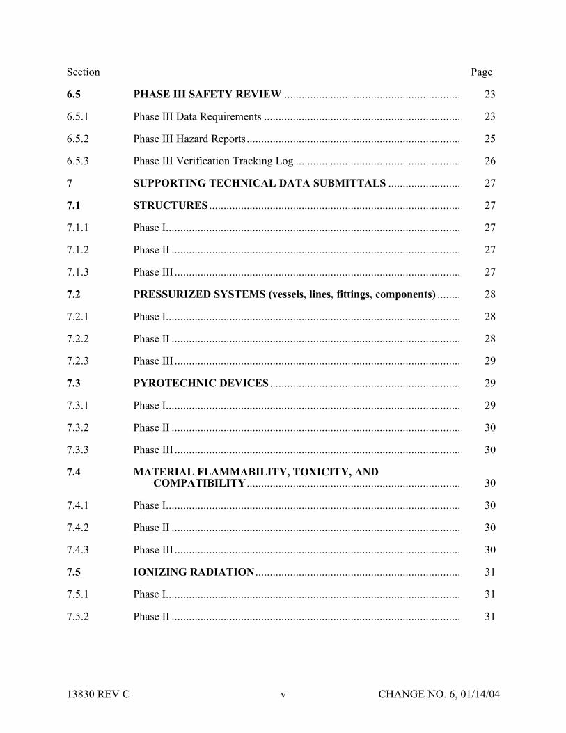
Section Page
65 PHASE III SAFETY REVIEW 23
651 Phase III Data Requirements 23
652 Phase III Hazard Reports 25
653 Phase III Verification Tracking Log 26
7 SUPPORTING TECHNICAL DATA SUBMITTALS 27
71 STRUCTURES 27
711 Phase I 27
712 Phase II 27
713 Phase III 27
72 PRESSURIZED SYSTEMS (vessels lines fittings components) 28
721 Phase I 28
722 Phase II 28
723 Phase III 29
73 PYROTECHNIC DEVICES 29
731 Phase I 29
732 Phase II 30
733 Phase III 30
74 MATERIAL FLAMMABILITY TOXICITY AND COMPATIBILITY 30
741 Phase I 30
742 Phase II 30
743 Phase III 30
75 IONIZING RADIATION 31
751 Phase I 31
752 Phase II 31
13830 REV C v CHANGE NO 6 011404
Section Page
753 Phase III 31
76 NON-IONIZING RADIATION 31
761 Phase I 31
762 Phase II 31
763 Phase III 31
77 PAYLOAD COMMANDING 32
771 Phase I 32
772 Phase II 32
773 Phase III 32
78a ELECTRICAL (POWER BONDING AND GROUNDING)SUBSYSTEMS 32
78a1 Phase I 32
78a2 Phase II 32
78a3 Phase III 32
78b AVIONICS CONTROL 32
78b1 Phase I 32
78b2 Phase II 32
78b3 Phase III 33
78c COMPUTER SYSTEMS (Avionics) 33
78c1 Phase I 33
78c2 Phase II 33
78c3 Phase III 33
79 MECHANISMS IN CRITICAL APPLICATIONS 33A
791 Phase I 33A
792 Phase II 33A
793 Phase III 33A
13830 REV C vi CHANGE NO 6 011404
Section Page
710 SOLID ROCKET MOTORS 33A
7101 Phase I 33A
7102 Phase II 33B
7103 Phase III 33B
711 BATTERIES 33B
7111 Phase I 33B
7112 Phase II 33B
7113 Phase III 33C
712 FLUID PROPULSION SYSTEMS 33C
7121 Phase I 33C
7122 Phase II 33D
7123 Phase III 33E
713 SEALED CONTAINERS (STRUCTURES) 33E
7131 Phase I 33E
7132 Phase II 33F
7132 Phase III 33F
8 VARIATIONS OF THE SAFETY REVIEW PROCESS 34
81 VARIATIONS FOR INTEGRATED MULTIPAYLOAD CARGO COMPLEMENTS 34
82 VARIATIONS FOR ISS PAYLOADS 34
821 On-orbit Reconfigured Payloads 34
822 Payloads Returning to Earth 35
9 REFLOWN AND SERIES PAYLOAD HARDWARE 36
10 PAYLOAD SAFETY NONCOMPLIANCE REPORT 38
101 NCR SUBMITTAL 38
13830 REV C vii CHANGE NO 6 011404
Section Page
102 TYPES OF SAFETY NCRs 38
1021 Waivers 38
1022 Deviations 38
11 LIST OF FORMS 39
111 JSC FORMS 39
112 KSC FORMS 39
12 APPLICABLE DOCUMENTS 40
APPENDIX A DOCUMENT MATRIX A-1
APPENDIX B ACRONYM LIST B-1
13830 REV C viii CHANGE NO 6 011404
SECTION 1 INTRODUCTION
Implementation of the payload safety process is the joint responsibility of the Payload Organization (PO) the flight operator Lyndon B Johnson Space Center (JSC) and the launchlanding site operator John F Kennedy Space Center (KSC)
The International Space Station (ISS) and Space Shuttle Program (SSP) safety policies and requirements for ISS and Shuttle payloads are specified in the current version of NSTS 17007ldquoSafety Policy and Requirements for Payloads Using the Space Transportation Systemrdquo and the current version of the NSTS 17007 ISS Addendum ldquoSafety Policy and Requirements for Payloads Using the International Space Stationrdquo In addition unique ground safety policies and requirements are specified in the current version of 45 SPW HB S-100KHB 17007 ldquoSpace Shuttle Payload Ground Safety Handbookrdquo These documents require the PO to conduct asystematic safety analysis and to document and submit a Safety Data Package (SDP) in support of safety reviews to be conducted by the flight operator (JSC) and the launchlanding site operator (KSC)
National Aeronautics and Space Administration (NASA) Headquarters has assigned the responsibility to review submitted payload safety documentation to the Space Shuttle and Space Station Program Directors at JSC and the Director of Safety and Mission Assurance at KSC The JSC Payload Safety Review Panel (PSRP) will assess the payload design and flight operations the KSC Ground Safety Review Panel (GSRP) will assess the Ground Support Equipment (GSE) design and ground operations These two panels were formed to accomplishthe following
bull Assure that PO interpretation of the safety requirements is consistent with NASA payload safety policy
bull Conduct safety reviews as appropriate during the development of the payload associated GSE and related operations
bull Evaluate hazard analyses and Noncompliance Reports (NCRs) bull Negotiate the resolution of safety issues involving design and operation to ensure compliance
with all applicable safety requirements bull Assess payload design features that have been implemented for controlling identified hazards
and the verification approach that confirms intended system performance
13830 REV C 1 CHANGE NO 6 011404
SECTION 2 PURPOSE
The purpose of this document is to define the payload safety review process in order to assist the ShuttleISS POs in documenting compliance with the payload requirements documents specified in section 1 Specifically this document accomplishes the following
bull Defines the safety reviews necessary to comply with the system safety requirements that are applicable to payload design flight operations GSE design and ground operations for both ISS and Space Shuttle
bull Identifies the required content of the SDP bull Describes preparation for and conduct of the safety review bull Establishes the timeline for data submittal and establishes the depth of detail required for the
various submittals bull Explains safety review process variations bull Defines the payload seriesreflight review process
13830 REV C 2 CHANGE NO 6 011404
SECTION 3 SCOPE
Data submittal requirements included herein apply to hardware being submitted to both the PSRP and the GSRP unless specified otherwise This document outlines the minimum data submittal requirements the PSRP and the GSRP reserve the right to request additional data as deemed necessary to support safety documentation
The objective of the safety review process is to review the payload GSE and operations for adequate safety implementation The mission success and any scientific objectives of the payload are the responsibility of the PO and are beyond the scope of this document and process
This document does not establish design requirements
31 APPLICABLE HARDWARE
This document applies but is not limited to the following payload hardware that fliesoperates on the Space Shuttle andor ISS during any mission phase (prelaunch launch ascent on-orbit entry landing or postlanding)
bull New Payload Hardware bull Existing (reflown and series) Payload Hardware bull Hardware Associated with Developmental Test Objectives (DTOs) Detailed Supplemental
Objectives (DSOs) Risk Mitigation Experiments (RMEs) Space Medicine Program (SMP) and Human Exploration and Development of Space Technology Demonstrations (HTDs) Experiment Hardware
The document also applies but is not limited to the following payload-related hardware
bull Government-Furnished Equipment (GFE) bull Airborne Support Equipment (ASE) bull GSE
32 EXPORT CONTROL
The PSRP complies with the United States export control laws and regulations as established by the US Department of Commerce in the Export Administration Regulations (EAR) and the US Department of State in the International Traffic in Arms Regulations (ITAR) The PSRP also complies with the Space Shuttle Programrsquos export control policy in NSTS 07700 Volume V and the ISSPrsquos export control policy in SSP 50223
13830 REV C 3 CHANGE NO 6 011404
Export control factors significantly into two areas of the payload safety review process
bull Distribution of Payload Data
bull Conduct of Safety Reviews
The PSRP Executive Secretary serves as the primary exporter of payload data to the ISS International Partners (IPs) and other foreign persons in support of the payload safety review process Payload data includes safety data packages hazard reports safety review presentation materials and other payload related information Specific export control data submittalrequirements for payload organizations are listed in section 4315 of this document
The PSRP Executive Secretary takes special precautions when conducting safety reviews for payloads under export control restrictions These precautions may include restricting attendance limiting presentation materials posting signs or conducting the review in a secure facility
13830 REV C 3A CHANGE NO 6 011404
SECTION 4 RESPONSIBILITIES OF THE PAYLOAD ORGANIZATION
The PO is responsible for assuring the safety of its payload and for complying with the safety requirements contained in the technical requirements documents cited in section 1 To this end the PO must accomplish the following
bull Perform a Safety Analysis bull Identify Hazards bull Document Compliance with the Safety Requirements bull Present the Documentation to the PSRPGSRP
41 SAFETY ANALYSIS
To meet the requirements of the current version of NSTS 17007 and NSTS 17007 ISS Addendum paragraph 301 the PO shall perform a safety analysis of the payload and GSE The analysis shall consider hardware design verification testing and flightground operations The safety analysis shall begin during the payload concept phase and shall be refined and expanded as the design matures For situations in which payload hardware will be installed orreconfigured on-orbit or in which the payload will be on-orbit for an extended time safety analyses shall consider the necessity of on-orbit verificationreverification of hazard controls
411 Level of Analysis
In order to identify the hazards applicable to a payload the PO shall conduct safety analyses both at the system and subsystem levels Each system and subsystem shall be evaluated to determinethe applicability of each technical safety requirement
Selection of subsystem groupings varies and any convenient grouping may be used The following is a suggested list of subsystems biomedical caution and warning cryogenic electrical environmental control human factors hydraulics materials mechanical opticalpressure systems propulsion pyrotechnics radiation and structures
For hardware developed for or provided to the PO the PO shall
bull Obtain the appropriate safety data from the supplier or conduct an independent safety analysis
bull Conduct a safety analysis of the interfaces between the subject hardware and other elements
412 Analysis Techniques
Depending on the complexity of the payload the PO should use established analytical techniques (eg preliminary hazard sneak circuit fault tree operational hazard and failure modes and effects analyses) to obtain the data necessary to complete present and support payload hazard reports
13830 REV C 4 CHANGE NO 6 011404
413 Safety Verifications for Payloads with Catastrophic Hazard Potential (Flight Only)
The current version of NSTSISS 18798 specifies data requirements to document the verification program for payload systemssubsystems that have catastrophic hazard potential An excerpt from this document is included below for convenience
Table 4-1 - NSTSISS 18798
All payload systems having catastrophic hazard potential for the orbiter or crew as a result of operations in or near the orbiter must use hardware and procedures that have been subjected to a rigorous verification program Verification programs normally require testing to verify adequate performance margins under all environmentalconditions (qualification testing) as well as demonstrating intended system performance on flight hardware Comprehensive system-level testing on payload flight hardware supported by qualification test on protoflight or flight type hardware are the preferred verification methods It is essential that payload system performance be verified from the input stimuli to the end function
Safety-critical system performance that cannot be verified by test shall be verified by independent parties using dissimilar analysis techniques whenever possible Single party analytical efforts can be used to verify performance only when the methodology is widely accepted and conservative margins are applied to the results
The payload organization must focus its attention to all parts of the payload verification program and orbiter interface verification activities to assure that the sub-elements of the total verification program are integrated into a comprehensive system verification effort that confirms the intended system performance When the use of ground test equipment(apparatus) is required to replace flight hardware functions verification methods shall be developed by engineering personnel independent from those designing the flight systemTest requirements procedures and test apparatus shall be derived from intended functional requirements rather than from the design and all items must be maintained under strict configuration control The payload organization is responsible for developing and presenting sufficient data to the PSRP [GSRP] to substantiate that the test requirements procedures and test apparatus will provide an adequate simulation in substitution for the end function
42 HAZARD IDENTIFICATION
The primary objectives of the safety review process are to identify the potential hazards applicable to a payload including its flight GSE and ground operations and to assure that the hazard controls and verifications (including on-orbit verificationreverification of hazard controls where applicable) are adequate and in compliance with the safety requirements To assist the PO in accomplishing these objectives appropriate safety terminology has been defined in the current version of NSTS 17007
Although not exhaustive the following is a list of some previously identified flight hazard groups that have been used on hazard reports collision contamination corrosion electrical shock explosion fire injury and illness loss of orbiter entry capability and inability to egress
13830 REV C 5 CHANGE NO 6 011404
The following are basic hazard groups applicable to ground operations structural failure of support structures and handling equipment collision during handling inadvertent release ofcorrosive toxic flammable or cryogenic fluids loss of habitablebreathable atmosphere inadvertent activation of ordnance devices ignition of flammable atmospherematerial electrical shockburns personnel exposure to excessive levels of ionizing or nonionizing radiation use of hazardousincompatible GSE materials inadvertent deployment of appendages working under suspended loads and rupture of composite epoxy overwrapped pressure vessels
43 DOCUMENTATION OF COMPLIANCE WITH THE SAFETY REQUIREMENTS
The safety analysis results shall be documented in the SDP which includes applicable payload hazard report forms (JSC Form 542B and JSC Form 1230) and presented to both the JSC PSRPand the KSC GSRP as described in this document Guidelines for completing the flight hazardreport forms and preparing the SDPs are found in JSC 26943 ldquoGuidelines for the Preparation of Payload Flight Safety Data Packages and Hazard Reports for Payloads Using the Space Shuttlerdquo current issue
For SDP preparation the PO is responsible for using the current version of all applicable forms and safety documentation The PO may verify current formsdocuments by contacting theExecutive Secretary to the PSRP or the Chairman of the GSRP These forms are listed in section 11
431 Data Submittals
Although there will be some duplication of material contained in data submittals prepared for PSRP and GSRP reviews each package serves a different purpose and must stand alone
Data submittals which may include SDPs and other supporting information (eg action item responses) should identify the flight on which the payload is manifested (if known) and be formally submitted in English to the Executive Secretary PSRP or the Executive Secretariat GSRP Data should be formally transmitted under the signature of the Program Manager
Safety review meetings are scheduled to be held approximately 45 calendar days after receipt of an acceptable SDP (ie an SDP that satisfies all the requirements in this document)
The SDP will be made available to the PSRPGSRP members and various other NASAcontractor technical and administrative personnel who support the Panels For ISS payloads this may include International Partner representatives to the PSRP
Payload safety data must be submitted electronically via the Internet using the Payload Safety Data Management System (DMS) located at the following URL
httppsrpjscnasagov
The DMS System Administrator (tel 281-483-9078) can provide information on acceptable software applications electronic addresses detailed login instructions and system procedures POs may also access the DMS via a hyperlink at the top of the Payload Safety homepage located at the following URL
13830 REV C 6 CHANGE NO 6 011404
httpwwwsrqajscnasagovpce
POs must obtain approval from the PSRP Executive Secretary or Executive Secretariat GSRP to submit flight or ground safety data respectively by alternate means or to submit supplementary data in hard copy format Hard copy submittals must be single-sided and sequentially paginated from the cover sheet to the last page of the package
Once the SDP has been electronically submitted the PO must send the transmittal lettersdocument signature pages and signed original Hazard Reports (HRs) to the appropriate Panel contact
Executive Secretary PSRPNASA Lyndon B Johnson Space Center
Mail Code NC4 2101 NASA Road 1
Houston TX 77058-3696
Executive Secretariat GSRP NASA John B Kennedy Space Center
Mail Code UB-F3 Kennedy Space Center FL 32899-0001
13830 REV C 6A CHANGE NO 6 011404
4311 Submittal of Proprietary Data
If proprietary data are submitted in the SDP the transmittal letter must include the following statement
This payload safety data package contains proprietary data on the following pages [listthe appropriate page numbers] [Insert name of the payload organization] acknowledges awareness and acceptance of the GSRP and the PSRPrsquos policies and methods of processing proprietary data [Insert name of the payload organization] also will provideany additional protective measures it deems necessary over and above that provided by the panels during meetings
The transmittal letter and the first page of the SDP must identify the specific pages that contain proprietary information Insert the word ldquoPROPRIETARYrdquo at the top and bottom of each pagethat contains proprietary data The word ldquoPROPRIETARYrdquo shall be in all capital letters in alarge font size and style that is easily discernible from the rest of the text
In addition to the proper submittal of proprietary information the PO should be aware of the following while attending PSRPGSRP safety reviews Technical Interchange Meetings (TIMs) and action item closure meetings
bull PSRPGSRP meetings are not conducted in secure facilities Thus when it is necessary torecess meetings (eg lunch and breaks) the POs will be responsible for protecting any proprietary data distributed during the meeting (other than that logged and distributed byNASA as part of the SDP)
bull If any proprietary data are to be presented or discussed during the meeting prior to the meeting the PO will notify the PSRP Executive SecretaryGSRP Chairman who will then make arrangements to monitor attendance close the doors and post a sign noting that accessto the meeting is controlled
bull The PO will be responsible for retrieval and disposition of any proprietary material distributed at the meeting (other than that logged and distributed by NASA as part of the SDP) with the exception that two copies of proprietary material distributed by the PO at the meeting will be retained by the PSRPGSRP in a protected file
When the PSRPGSRP receives proprietary data included in the SDPs such data will be handledin a manner that will protect the interests of the PO These procedures include trackingdistributed materials protecting files and restricting reproduction In order to exercise reasonable care in protecting proprietary data in connection with the payload safety review process NASA will ensure that proprietary data are distributed only to persons who have a needto review such data in support of panel functions Furthermore distributed data that is returned to the PSRP Executive SecretaryGSRP Chairman after use will be destroyed via the NASAsecure disposal process
13830 REV C 7 CHANGE NO 6 011404
The protection of material marked ldquoPROPRIETARYrdquo creates an added burden on thePSRPGSRP review support system so the PO should mark only those items that are proprietary The PO should coordinate with the PSRP Executive SecretaryGSRP Chairman to explore such alternatives as providing the proprietary material in a separate package when it is a very small portion of the overall SDP If a separate proprietary briefing package (not containedin the SDP) is to be presented to the PSRPGSRP during the review the PO shall provide at least20 copies of such material for distribution at the review
If the PO discovers that some portion of the SDP marked ldquoPROPRIETARYrdquo is no longerconsidered such the PO must inform the PSRP Executive Secretary andor the GSRP Chairmanin writing
4312 Submittal of Copyrighted Data
Payload organizations are hereby informed that payload documentation submitted to NASA must be reproduced and distributed to the members of the PSRPGSRP and to associated technicalsupport personnel Accordingly copyrighted data shall not be included in the submitteddocumentation unless the PO 1) identifies such copyrighted data and 2) grants to theGovernment or acquires on behalf of the Government a license to reproduce and distribute the data to these necessary recipients
4313 Submittal of Translated Data
For all documents submitted by the PO to the PSRPGSRP that have been translated intoEnglish the English translation shall be the official document
4314 Submittal of Toxicological Data for SSP and ISS Payloads (Flight Only)
The ShuttleISS payload safety review process requires biomedical safety assessments of potentially hazardous materials such as chemicals microorganisms and radioisotopes In order for these assessments to be available for the safety reviews the JSC Toxicology Group requires POs to submit test sample data substantially in advance of the safety reviews See JSC 27472 ldquoRequirements for Submission of Test Sample-Materials Data for Shuttle Payload Safety Evaluationsrdquo current issue for the timeline and data requirements for these early submittals The PO must attach both the data submitted to JSC Toxicology Group and the JSC response (when available) to the applicable hazard report that is a part of the SDP Should toxicology submittals involve proprietary data see section 4311
4315 Submittal of Export Control Data (Flight Only)
The export control data submittal requirements in sections 43151 and 43152 apply to USpayload organizations only IP payload organizations are not required to provide the US export control classification of their safety data packages In the event that an IP SDP requires a USexport control classification NASA export control resources will be used to classify the SDP
13830 REV C 8 CHANGE NO 6 011404
43151 ISS Payloads
Distribution of ISS payload safety data packages to the ISS IPs is a standard part of the payload safety review process
The PO must identify the export control classification of the SDP payload data in its transmittal letter The first page of the SDP must also identify the export control classification of the data
The PSRP Executive Secretary will not distribute an SDP with an unknown export controlclassification to the IPs Safety reviews may be delayed or cancelled for ISS payloads with unresolved export control issues
The POrsquos safety review presentation materials must have the same export control classification as the SDP submitted for review or a less restrictive export control classification
43152 Shuttle Payloads
Distribution of Shuttle payload safety data packages to the ISS IPs is not a standard part of the payload safety review process
Shuttle payload safety data packages are not distributed to the IPs unless the PSRP identifies a specific need to do so If a need is identified the PSRP Executive Secretary will work with the PO and the SSPrsquos export control resources to obtain the export control classification of the SDP
The PO may include the export control classification of the SDP payload data in its transmittalletter and on the first page of the SDP if the classification is known prior to SDP submittal
432 Hazard Reports
The purpose of the hazard reports is to document the POrsquos safety assessment in a manner that reflects how the payload design demonstrates compliance with the safety requirements The hazard reports are used as a method to systematically assess compliance with the safety requirements
The flight SDP submittal must contain all flight hazard reports the ground SDP submittal mustcontain all ground hazard reports Each hazard report must be signed and dated by the payloadprogram manager prior to submittal Hazard reports shall be prepared on JSC Form 542B JSCForm 542B-1 or JSC Form 1230 (see section 11) or an equivalent form that contains all information required on the JSC forms Section 7 organized by area of design identifies minimum support data for flight hazard reports JSC 26943 contains guidelines for preparingpayload flight hazard reports
13830 REV C 8A CHANGE NO 6 011404
Following any technical discussion the PSRPGSRP Chairman will provide a disposition for each hazard report This disposition may take one of the following forms 1) approved aswritten 2) approved with modification 3) approved with an action to be performed by the PO andor PSRPGSRP and 4) not approved
The PO is responsible for retaining and maintaining the original hazard reports after approval
44 SAFETY REVIEW PRESENTATION
The PO should be prepared to present information submitted in the SDP to the appropriate safety panel during scheduled reviews (see sections 611 and 612) During reviews the PO shouldprovide briefing chart handouts sufficient for the number of people expected to attend the review
13830 REV C 9 CHANGE NO 6 011404
SECTION 5 SAFETY REVIEW OVERVIEW
51 LOCATION
Safety reviews for payload design and flight operations are usually conducted at JSC The safetyreviews for GSE design and ground operations will normally be conducted at KSC The PO shall coordinate the timing of the PSRP reviews with the PSRP Executive Secretary The PO shall coordinate the timing and location of the GSRP reviews with the GSRP Chairman
52 INITIAL CONTACT MEETING
The PO may receive initial contact safety briefings by the JSC and KSC safety representatives The JSC briefing normally held during the first integration meeting at JSC should be scheduledby contacting the Payload Integration Manager (PIM) at JSC For ISS payloads contact the ISSPIM The KSC briefing is usually held in conjunction with the first Ground Operations Working Group (GOWG) meeting which is scheduled through the Launch Site Support Manager Integration Manager (LSIM) at KSC
The briefing includes an overview of the technical and system safety requirements to be met by the PO plus instructions for conducting the safety reviews The PO should provide a schedule ofpayload milestones and request a phase 0 or phase I safety review when the payload design concept has been developed
53 TYPES OF MEETINGS
Safety reviews may take place in person via teleconference or by correspondence Review meetings may be formal or out-of-board as deemed appropriate by the Panel Chairman
bull Formal Meeting Formal meetings constitute a gathering of the safety review panel representatives of the PO and the appropriate supporting technical staff
bull Out-of-Board Meeting Out-of-board meetings do not require the full safety panel Attendees may include the Panel Chairman Safety representative(s) representatives of the PO and others necessary to address the issues that may be involved
bull Safety TIM The review panel andor associated technical staff may convene upon request in order to assist in interpreting safety requirements or to coordinate safety analysesissues prior to safety reviews Requests for flight safety TIMs should be coordinated with the PSRP Executive Secretary Requests for Ground Safety TIMs should be coordinated with the GSRP Chairman Material to be addressed during the TIM should be provided 14 calendardays prior to the TIM
bull Splinter Meetings Splinter meetings may be held concurrently with a safety review to discuss detailed technical concerns
13830 REV C 10 CHANGE NO 6 011404
54 PAYLOAD CATEGORIES
Traditional payload safety compliance assessment is accomplished using a phased safety review process (phases 0 I II III) that corresponds to the hardware conceptual preliminary and critical design review phases and verificationvalidation of the payload (see section 6) Successful completion of each safety phase is documented by SDPHR submittals to and approval by the PSRPGSRP
To streamline this process the PSRP has implemented procedures and data requirements to minimize formal PSRP review time for payloads with routine hazardsstandard controlsverifications This allows the PSRP to concentrate review time on payload systems withthe highest hazard potential ldquomust-workrdquo functions andor nonstandard controls and verification methods POs may document routine hazards and standard controls and verifications on the JSC Form 1230 ldquoFlight Payload Standardized Hazard Control Reportrdquo
Based on the phase I SDP new payloads are categorized by the PSRP into one of three categories of complexity (basic intermediate or complex) with respect to hazard potential as shown in Table 5-1 below The review process is then tailored to the complexity of the payload design and adequacy of documentation In addition the process permits all payloads to document standard hazards that have standard controls and verifications on JSC Form 1230 which may be approved by the PSRP without a formal PSRP meeting Details concerning basicand intermediate categories are contained in sections 541 and 542 respectively Complexpayloads use the review process detailed in section 6 Reflown and series payloads use thereview process outlined in section 9
Table 5-1 - PAYLOAD CATEGORIES
PayloadCategory
Defined Hazards
Basic The only hazards identified are ldquostandardrdquo as specified on the JSC Form 1230 The appropriate hazard controls are found on JSC Form1230
Intermediate 1) The payload has ldquouniquerdquo hazards (ie hazards not found on the JSC Form 1230) but has controls and verification methods that have been historically accepted by the PSRPOR
2) The payload has ldquostandardrdquo hazards (ie hazards identified on the JSC Form 1230) but uses controls and verification methods other than those identified on the JSC Form 1230
Complex The payload has unique hazards with hazard controls that are
a Active ldquomust workrdquo functions such as electromechanical or pyrotechnic separation systems or actuatorsmechanisms providing structural load paths
OR b Nonstandard or have nonstandard verification methods that
depart from historically accepted techniquesOR c Operationally complex requiring flight or ground personnel
intervention to assist in controlling the hazard
13830 REV C 11 CHANGE NO 6 011404
If after a payload category has been assigned the PO a) identifies previously undefined hazards or b) implements design changes that may create new hazards the PO must submit a revisedSDP which may result in a reclassification of the payload category
541 Review Process for Basic Payloads (Flight Only)
Basic payloads (see Table 5-1 above) have a very low level of complexity which may allow the payload to complete the safety process out of board However the PO will submit an SDP that will document the applicable hazards controls and verifications Submittal will follow the standard procedure detailed in section 431 and approval may be obtained without a meeting The following data are required for the simplified SDP for hardware design and flight operations
bull Brief description of the hardware design and flight operations with schematics and block diagrams as appropriate
bull Summary of the safety analysis results that documents compliance with the design verification and applicable on-orbit verificationreverification requirements for the identified standard hazards
bull Documentation of all applicable hazards controls and verifications on hazard report(s) (eg JSC Form 1230Form 542)
bull Certificate of Payload Safety Compliance (JSC Form 1114A) signed by the ProgramManager
542 Review Process for Intermediate Payloads (Flight Only)
In addition to the standard hazards found in Basic payloads the Intermediate payload has unique hazards that have standard controls and verification methods (including applicable on-orbit verificationsreverifications) that have been historically accepted by the PSRP Intermediate category payloads should require one or two reviews of the unique hazards but the basic hazards may be addressed on a Form 1230 and approved out of board The PSRP will determine the need for a second review for unique hazards at the completion of the first review The determination will be based primarily upon the completeness and quality of the unique hazard reports Requirements for SDP submittal are the same as those stated in section 431
55 SCHEDULE OF REVIEWSPHASES
The schedule for formal phase 0 I and II payload safety reviews generally relates to the payload development schedule Phase 0 is held during the concept phase or at the start of payload design Phase I is near the Preliminary Design Review (PDR) phase II is near the Critical Design Review (CDR) The PO should set the review schedule to obtain maximum benefit to payloaddevelopment based on the results of the safety reviews
ISS payloads may include multiple major systems or components each working to a uniqueschedule These may be individually baselined and categorized (see section 54) which allows them to progress through the payload safety process in accordance with their own schedule (see section 82)
13830 REV C 12 CHANGE NO 6 011404
Phase III is associated with completion of payload safety verifications andor the start of ground processing When establishing a timeline for phase III the PO should allow enough time to closepotential issues that may result from a phase III review The timing and completion of the phase III review and safety certification are critical to the launch schedule The flight and ground phaseIII completion requirements restated below are in the current version of NSTS 17007 and NSTS 17007 ISS Addendum and apply to all payloads
The JSC and KSC Phase III safety review and ground safety certification must be completed 30 days prior to delivery of the payload ASE and GSE to the launch sitehellip
If any verification items remain open on the flight hazard reports the PO must provide rationale to support the safety of starting ground processing with these items open The rationale is to be submitted to both the PSRP and GSRP The PSRP will review the rationale and provideconcurrence to the GSRP
To schedule KSC Ground safety reviews contact the GSRP Chairman to schedule JSC Flight safety reviews contact the PSRP Executive Secretary (see section 431)
56 SAFETY REVIEW COMPLETION
561 Documentation of Phase Completion
During a formal meeting the Panel Chairman will make an official announcement that the safety phase is complete or incomplete (open) This announcement will be recorded and distributed bythe PSRPGSRP in the official meeting minutes Incomplete phases are usually attributable to overdueopen action items or unsigned (open) hazard reports The PSRPGSRP will issue officialcorrespondence to document closure of open action itemssignature of open hazard reports thatoccurs after the phase review The correspondence that closes the last open action itemhazardreport for that phase will include a statement that the safety phase is considered complete
For out-of-board reviews safety review process completion will be documented by formal correspondence
562 Completion Criteria for Phase I II and III
Successful completion of phase I and II reviews is accomplished by obtaining approval (Panel Chairmanrsquos signature) of hazard reports at the appropriate phase level and closure of applicable phase III action items
After submission of all required data the criteria for successful completion of the safety review process at the phase III level for both flight and ground reviews are as follows
bull All payload hazard reports are signed by the payload Program Manager and the Panel Chairman at the phase III level
bull All NCRs are approved bull Safety review action items are formally closed in the safety review meeting minutes or
documented closed in separate correspondence bull A signed Certificate of Ground Payload Safety Compliance provided to the GSRP (for phase
III ground safety)
13830 REV C 13 CHANGE NO 6 011404
Approval of the phase III safety data by the PSRP and GSRP is with the understanding that the data represent the actual design and operations of the payload Should safety issues arise after the safety process is complete the safety panels reserve the right to request additional data deemed necessary to reassess the payload
563 Completion Criteria for SeriesReflight
The criteria for successful completion of a series or reflight safety review is that all data required by section 9 Reflown and Series Payload Hardware have been submitted and approved
57 POST PHASE III SAFETY ACTIVITY
571 Certificate of Flight Payload Safety Compliance
The PO must present a signed Certificate of flight Payload Safety Compliance to the PSRP Executive Secretary no later than 10 days prior to the Flight Readiness Review (FRR)
572 Configuration Control
When changes to the design configuration or operations of the payload are required subsequent to phase III the PO shall assess those changes for possible safety implications including the effect on all interfaces The assessment shall be forwarded to the PSRPGSRP for review andapproval If the change has ground safety implications it must be reviewed with the KSC panel prior to proceeding with ground processing New or revised hazard reports and support datashall be prepared where applicable and submitted for approval as indicated in section 431 The need for delta phase III safety reviews will be determined by the PSRPGSRP Chairman Satisfactory completion of these activities is mandatory prior to the start of affected ground activities or launch
Any test failures anomalies or accidents involving payload flight hardware or software that occurs between the completion of phase III and launch must be promptly reported to the PSRPGSRP Safety impacts if any should be identified
573 Verification Tracking Log
Open verification items must be tracked on a flight or ground safety Verification Tracking Log (VTL) (see section 11)
bull Flight Safety From Phase III until L-60 days the PO shall update and provide the VTL to the PSRP Executive Secretary once a month From L-60 days until launch the PO shall provide a weekly update to the VTL All VTL open items must be closed no later than 4PM Central time on the last business day prior to launch Items that cannot be closed at this time will require the transmission of a facsimile closing the open VTL items to the Mission Evaluation Room (MER) at NASA JSC no later than L-6 hours Contact the PSRP Executive Secretary for MER delivery instructions
bull Ground Safety The initial submittal of the ground safety VTL is required with the phase III ground SDP Following the completion of the phase III review the ground safety VTL shall be updated monthly prior to hardware arrival at KSC If there are open flight verifications
13830 REV C 14 CHANGE NO 6 011404
that are constraints to ground processing the PO must also include those items of the flight VTL After the delivery of the payload ASE or GSE to the launch site the safety VTL(s) shall be updated at least weekly More frequent updates to the safety VTL(s) may be required if the open items must be closed to allow work to continue
574 Documentation of Safety Process Completion
Final flight safety approval is documented by the PSRP Chairmanrsquos signature on the Certificateof Flight Readiness (CoFR) for the planned flight
Final ground safety approval is documented by a letter from the KSC Director Safety Assurance to the KSC Director Customer Service Space Station and Shuttle Payloads Processing statingthat the Ground Safety Review Process has been completed and the payload may begin ground processing
13830 REV C 15 CHANGE NO 6 011404
SECTION 6 SAFETY PROCESS
61 GENERAL
611 Preparation
In preparation for a phase safety review the PO will submit an SDP as indicated in section 431 If phase reviews are combined (eg a phase III review) the SDP shall include the datarequirements that apply to all the appropriate phases The depth and number of the plannedreviews are dependent on the complexity technical maturity and hazard potential of the payload and may be modified by the Panel Chairman in conjunction with the PO
The PO should provide sufficient technical support personnel to answer questions posed by the PSRPGSRP in support of the agenda items
Listed below are general agenda topics for safety review meetings These insure that the safety review meetings proceed smoothly and contain the necessary information to facilitate the review
612 General Meeting Agenda Guidelines
The PO should coordinate all meeting agenda with the PSRP Executive Secretary or the GSRP Chairman prior to the safety review meeting and provide the final agenda in advance The fundamental elements of all Safety Review Meeting Agenda are as follows
a Introduction of the Meeting and Participants by the JSC Safety Reliability and Quality Assurance (SRampQA) Payload Safety Engineer (PSE)
b Opening Remarks by Chairman and the Payload Program Manager
c Discussion of Pre-Review Activity Led by the PSE
d Program-level Overview (including areas of responsibility)
e Program Milestone Schedule Provide the Program Milestone Schedule includingbut not limited to
(1) design stages and reviews
(2) hardwaresoftware build status
(3) testing and verification activities
(4) delivery integration and launch activities and
(5) safety review dates
f Mission Objectives including overview of mission objectives and general criteria for a successful mission
13830 REV C 16 CHANGE NO 6 011404
g SystemSubsystem Technical Presentation Overview including enough information to allow the PSRPGSRP to gain a general technical understanding of the systemsinvolved in the payload operations Highlight any design changes since the previous safety reviews
h Operations Overview describing planned operations and known contingencies Plan to discuss detailed operations that relate to payload safety in conjunction with the appropriate hazard report presentation Highlight any operations changes made tothe operations that impact the safety of the payload since the previous review
i Safety Assessment Summary including safety assessments performed to identify hazards any failures or anomalies that occurred after development testing and the corrective actions Present responses to agreements and formal action items including a summary of open action items and associated plans for closure Provide sufficient information to demonstrate that a comprehensive hazard analysis has been performed Provide an overview of hazards and how they relate to the hazard reports and discuss safety-related items that are not reflected in the hazard reports
j Phase-specific Topics Additional phase-specific topics for the agenda should be drawn from the data that are required to be included in the SDP for that phase (see sections 621 631 641 and 651) If not included as one of the general agendatopics these data should be addressed as separate agenda items
k Hazard Report Presentation Unless otherwise agreed to by the PSRPGSRPpresent all hazard reports in full associated noncompliancereportswaiversdeviations previously assigned action itemsagreements that involved modification of hazard reports and associated action itemagreement responses
l Action Item Review Both the PO and the PSRPGSRP will review and agree toactions and due dates assigned during the course of the safety review to ensure that there are no misunderstandings These action items will be printed and signed during the review
m Closing Comments Payload Program Manager and Panel
62 PHASE 0 SAFETY REVIEW
The optional phase 0 safety review is provided as a service to the PO The objectives of the meeting are to
bull Assist the PO in identifying hazards hazard causes and applicable safety requirements early in the development of the payload
bull Adequately describe the hazard potentialbull Answer questions regarding the interpretation of the safety requirements or the
implementation procedures of this documentbull Provide guidance to the PO for preparing the safety data required for subsequent safety
reviews
13830 REV C 17 CHANGE NO 6 011404
621 Phase 0 Data Requirements
The following data are required for the phase 0 SDP and must be submitted as stated in paragraph 431
a For payload design and flight operations
(1) Conceptual payload description (including subsystems) and missionscenario
(2) Description of safety-critical subsystems and their operations
(3) Flight hazard reports (JSC Form 542BForm 1230)
b For GSE design and ground operations
(1) Conceptual payload description and brief mission scenario
(2) Conceptual GSE description and operations and description of payload design that is safety critical during ground operations
(3) Ground operations scenario
(4) Ground hazard reports (JSC Form 542B)
The description of the payload and its operation must be of sufficient detail to permit identification of all subsystems that may create hazards Emphasis should be given to thosesubsystems that store transfer or release energy The descriptions of the safety-critical subsystems must be of sufficient detail to identify the hazards in terms consistent with the conceptual design In addition the PO shall address tentative plans for any flight operation (eg extravehicular activity reverification of hazard controls) or ground operation that would require personnel certification to perform hazardous procedures
622 Phase 0 Hazard Reports
The purpose of a phase 0 hazard report is to document and scope the specific hazards identified It is intended to be a working document for discussion and critique at the phase 0 safety review and will not require signatures A hazard report must be prepared for each unique hazardidentified in the safety analysis The hazards contained on the phase 0 hazard report must reflect the payload conceptual design and operations existing at the time of the phase 0 review For phase 0 the PO may identify hazard controls verification methods or status of verifications
63 PHASE I SAFETY REVIEW
The purpose of the phase I safety review is to obtain PSRPGSRP approval of the updated safety analysis that reflects the preliminary design and operations scenario of the payload At this pointthe PO shall present a refined safety analysis that identifies all hazards and hazard causes inherent in the preliminary design evaluates all hazards for means of eliminating reducing or controlling the risk and establishes preliminary safety verification and on-orbit verificationreverification methods The PO shall provide a preliminary identification of the payload interfaces and of the hazards presented by these interfaces
13830 REV C 18 CHANGE NO 6 011404
631 Phase I Data Requirements
The following data are required for the phase I SDP and must be submitted as stated in paragraph 431
a For payload design and flight operations
(1) Updated payload description (including subsystems) and mission scenario
(2) Updated descriptions of safety-critical subsystems and their operations including schematics and block diagrams with safety features inhibits and controls identified Identify any safety-critical subsystems that are computer controlled and identify the functional architecture associated with that computer control
(3) Updated and additional flight hazard reports (eg JSC Form 542BJSC Form 1230) including appropriate support data (see section 7) For payloads thathave catastrophic hazard potential document the verification programoutlined in NSTSISS 18798
(4) A summary list (in the payload description) of orbiter- andor ISS program-provided critical services and an explanation (in the appropriate hazard reports) of the orbiter andor ISS services used to control andor monitorpayload hazards (NSTS 17007 and NSTS 17007 ISS Addendum current version)
(5) For ISS payloads a presentation of the Fire Detection and Suppression (FDS) implementation approach For sub-rack payloads the PO shall address the integrated system approach (using sub-rack services andor ISS services) to fully define the FDS implementation strategy In addition submit JSC Form 1428 to document methods and verifications used to detect and suppress a fire event for each payload volume
(6) Discussion of design features supporting verificationreverification of hazard controls on-orbit and associated constraints
(7) A tabulated list of tentative toxic materials and support data per JSC 27472(see section 4314)
(8) A list of all battery types their uses manufacturer and applications
(9) A preliminary description of all pyrotechnic devices and their functions
(10) Preliminary on-orbit maintenance safety assessment as outlined in NSTSISS 18798
b For GSE design and ground operations
(1) Updated payload description and brief mission scenario
13830 REV C 19 CHANGE NO 6 011404
(2) Updated descriptions of GSE payload subsystems that present a potential hazard during ground processing and their ground operations Schematics and block diagrams with safety features and inhibits identified should be included Design data for hazardous systems (pressure lifting etc) shall be summarized in a matrix Contact the GSRP Chairman for sample formats
(3) Updated ground operations scenario including postflight ground operationsat the primary alternate and contingency landing site The scenario should highlight unique payload requirements at the launch pad such as continuous power through a T-0 umbilical
13830 REV C 19A CHANGE NO 6 011404
(4) Updated ground hazard reports (JSC Form 542B) including appropriatesupport data
(5) Ordnance data required by the current version of KHB 17007 Appendix D
(6) Estimated KSC on-dock arrival date
632 Phase I Hazard Reports
The PO shall prepare phase I hazard reports for each hazard identified as a result of the safety analysis for the preliminary design and operations scenario of the payload Hazard reports shallbe added to or deleted from those agreed to during phase 0 to reflect the updated safety analysis Rationale for deleting a hazard agreed upon at phase 0 shall be presented during the phase I review
For phase I the PO shall identify hazard controls for each hazard cause identified at phase 0 A direct correlation between each hazard cause and the corresponding hazard control(s) must be clearly shown on the report Sufficient supporting information detailing each hazard control must be provided
Verifications should include the types of tests analyses inspections or procedures to be used to verify each hazard control including all orbiter- or ISS-provided services or interfaces both prelaunch and on-orbit A direct correlation between each verification method and the corresponding hazard control must be clearly shown on the report Each verification item should be independent and have a designator that allows for individual tracking of verification status
Manufacturingassembly proceduresprocesses that are critical in controlling hazards that cannot or will not be verified by subsequent inspection or test must be verified during the manufacturingassembly process An independent verifier as specified by the PO shall attest toproper completion of the procedureprocess Critical proceduresprocesses which require special monitored verification (Mandatory Inspection Points [MIPs]) shall be identified in preliminary fashion (NSTS 17007 and NSTS 17007 ISS Addendum current version)
If available the PO should provide a tentative schedule for completion of each verification taskand correlate with the integration schedule
64 PHASE II SAFETY REVIEW
The purpose of the phase II safety review is to obtain panel approval of the updated SDP that reflects the CDR-level design and operations scenario of the payload The phase II safety analysis identifies all hazards and hazard causes defines and documents implementation of a means for eliminating reducing or controlling the risks and documents finalized specific safety verification and on-orbit verificationreverification methods (test plans analysis and inspection requirements etc) Payload interfaces mission and ground operations procedures and timelines that were not addressed during the phase I safety review shall be assessed for safety hazards The payload interfaces to be assessed shall include those between the Shuttle andor ISS and the payload and among the various components that make up the payload (the spacecraft upper stages space platforms pallets experiments ASE ancillary flight equipment GSE KSC Facilities GFE etc) Newly identified hazards shall be documented in additional hazard reports For this review the PO should provide the estimated KSC on-dock arrival date
13830 REV C 20 CHANGE NO 6 011404
641 Phase II Data Requirements
The following data are required from the PO for phase II and must be submitted as stated in paragraph 431
a For payload design and flight operations
(1) Updated payload description (including subsystems) and mission scenario
(2) Updated descriptions of safety-critical subsystems and their operations including schematics and block diagrams with safety features and inhibits identified Provide electrical schematics that clearly identify the requirednumber of independent inhibits controls and monitoring provisions Present a summary of the test and analytical efforts required to verify the intended performance of all safety-critical hardware For a computer-based control system that is used to prevent criticalcatastrophic hazards provide the following datadescriptions bull Functional architecture bull Expected interactions bull Results of unexpected interactions bull Protections for common cause failures bull Development process for databases hardware software and
hardwaresoftware (3) Updated and additional flight hazard reports (eg JSC Form 542BJSC
Form 1230) including appropriate support data (see section 7) For payloads that have catastrophic hazard potential document the verification program outlined in NSTSISS 18798
(4) Updated summary list and explanation of orbiter- andor ISS-provided critical services
(5) For ISS payloads an update of the FDS implementation approach Include information on use of forced air flow wire derating circuit protection materials usage parameter monitoring (fan speeds temperatures currentetc) and responses to an out-of-limit condition and suppression approach For sub-rack payloads the PO shall address the integrated system approach (using sub-rack services andor ISS services) to fully define the FDS implementation strategy Updated JSC Form 1428 to reflect specific test (or analysis) procedures to be used along with the schedule for completion of FDS verification tests analyses or inspections
13830 REV C 21 CHANGE NO 6 011404
(6) Verification methods associated with hazard controls that require on-orbit verification andor reverification and the applicable approach (include rationale constraints and detailed methodology)
(7) An updated tabulated list of planned toxic materials and support data per JSC27472 (see section 4314) Updates should include changes in testmaterials changes in test conditions and any alternate test materials
(8) Updated list of all battery types their uses manufacturer and applications
(9) A list of all pyrotechnic devices their functions chemical composition critical components inspection plan verification plan and aging degradation evaluation plan
(10) List of hazard controls that require crew procedures andor training
(11) A record of test failures anomalies and accidents involving qualification or potential flight hardware Include a safety assessment for items which may affect safety
(12) The status of all action items assigned to the PO during phase I
(13) Detailed on-orbit maintenance safety assessment as outlined in NSTSISS 18798 Identify maintenance activities safe access areas and reverification of safety critical features
b For GSE design and ground operations
(1) Updated payload description and brief mission scenario
(2) Updated descriptions and matrices of the GSE the payload subsystems that present a potential hazard during ground processing and their ground operations Include updated schematics and block diagrams with safety features and inhibits identified Electrical schematics must show all payloadGSE grounding
(3) Updated ground operations scenario including postflight ground operations at the primary alternate and contingency landing sites
(4) Updated and additional ground hazard reports (JSC Form 542B) includingappropriate support data
(5) Updated ordnance data required by the current version of KHB 17007 Appendix D
(6) Updated KSC on-dock delivery date
(7) Specific engineering drawings and stress analyses of subsystems whenrequested by the GSRP Chairman
(8) A list of safety-related failures and mishaps that have occurred
13830 REV C 22 CHANGE NO 6 011404
(9) The status of all action items assigned to the PO during phase I
(10) A list of technical operating procedures that will be used at KSC with apreliminary designation as to which ones are considered hazardous
13830 REV C 22A CHANGE NO 6 011404
642 Phase II Hazard Reports
The PO shall prepare the phase II hazard reports by revising the phase I hazard reports to reflectthe completed payload design and flightground operating procedures If the payload designchanges from phase I to phase II so that a phase I hazard report may be deleted present a brief statement of rationale for deleting the report in the phase II SDP The GSRPPSRP willdisposition the hazard reports
Address all critical proceduresprocesses including the plan for verification Verifications shall refer to specific test (or analysis) procedures and summarize passfail criteria to be used Specifythe schedule for the completion of each specific verification test analysis or inspection
65 PHASE III SAFETY REVIEW
The purpose of the phase III safety review is to obtain PSRPGSRP approval of the SDP and safety compliance data that reflects the safety verification findings The focus of this review is to assess safety verification testing and analysis results If verifications critical for establishing the acceptability of the fundamental design of the payload for safety are not completed prior to the phase III review then subsequent reviews may be required prior to hazard report approval All verifications that are open at the time of the phase III SDP submittal must be included on the safety VTL Items listed on the VTL should be planned open work items such as groundprocessing at KSC
651 Phase III Data Requirements
The following data are required for the phase III SDP and must be submitted as stated in paragraph 431
a For payload design and flight operations
(1) Final as-built payload description (including subsystems) and mission scenario
(2) Updated descriptions that define the final configuration of the safety-critical subsystems and their operations including schematics and block diagramswith the as-built payload safety features and independent inhibits controls and monitoring provisions identified Address applicable features andconstraints relating to on-orbit verificationreverification of hazard controls
For a computer-based control system that is used to prevent criticalcatastrophic hazards provide verifications for the following bull Functional architecture bull Expected interactions bull Results of unexpected interactions bull Protections for common cause failures bull Flight article databases hardware software and hardwaresoftware
operate as designed
13830 REV C 23 CHANGE NO 6 011404
(3) Updated (and additional if required) flight hazard reports including support data that reflect the final configuration of the as-built payload and planned use For payloads that have catastrophic hazard potential document theverification program outlined in NSTSISS 18798
(4) Final summary list and explanation of orbiter- andor ISS-provided critical services
(5) For ISS payloads a finalized FDS implementation approach Include information on use of forced air flow wire derating circuit protectionmaterials usage parameter monitoring (fan speeds temperatures currentetc) and responses to an out-of-limit condition For sub-rack payloads the PO shall address the final integrated system approach (using sub-rack services andor ISS services) to fully define the FDS implementation strategy Final JSC Form 1428 to summarize the results of the completedtests analyses andor inspections and refer to particular test reports by document number title and date
(6) Updated (and additional if required) verification methods associated with hazard controls that require on-orbit verification andor reverification and the applicable approach (include rationale constraints and detailed methodology)
(7) A final tabulated list of toxic materials and support data per JSC 27472 (see section 4314) including additions and changes in test materials changes in test conditions and any alternate test materials
(8) A final list of all battery types their uses manufacturer and applications
(9) A final list of all pyrotechnic devices installed or to be installed on the payload The list will identify for each cartridge the function to be performed the part number the lot number and the serial number
(10) Updated list of hazard controls that require crew procedures and or training
(11) An updated record of test failures anomalies and accidents involving qualification or potential flight hadware or baselined flight software if the software is used for hazard control Include a safety assessment for items which may affect safety
(12) The status of all action items assigned to the PO through phase II
(13) Payload Flight Safety VTL (JSC Form 764)
13830 REV C 24 CHANGE NO 6 011404
(14) Identification of flight safety noncompliances Flight safety NCRs must be approved as either a waiver or a deviation before the phase III safety review can be completed A signed copy of each approved safety waiver andor deviation shall be included in the phase III SDP attached to the appropriate hazard report
(15) Finalupdated on-orbit maintenance safety assessment as outlined in NSTSISS 18798
b For GSE design and ground operations
(1) Final as-built payload description and brief mission scenario
(2) Updated descriptions and matrices defining the final configuration of the GSE the payload subsystems that are potentially hazardous during ground processing and their ground operations Include updated schematics andblock diagrams with the as-built safety features and inhibits identified
(3) Updated and finalized ground operations scenario including postflight ground operations at the primary alternate and contingency landing sites
(4) Updated and additional ground hazard reports including support data thatreflect the final configuration of the as-built GSE and planned payloadGSE use
13830 REV C 24A CHANGE NO 6 011404
(5) Updated and finalized ordnance data required by the current version of KHB 17007 Appendix D
(6) Updated and finalized KSC on-dock delivery date
(7) Specific engineering drawings and stress analyses of subsystems whenrequested by the GSRP Chairman
(8) A summary and safety assessment of all safety-related failures and accidents applicable to payload processing test and checkout Identify impact to theSpace Shuttle other payloads and facilities
(9) The status of all action items assigned to the PO through phase II
(10) Finalized list of technical operating procedures that will be used at KSC withthe hazardous procedures clearly identified The list shall also state the proposed first use of the procedure at KSC
(11) Verification that each payload flight system pressure vessel has a pressure vessel logbook that shows pressurization history fluid exposure and otherapplicable data This verification should account for the planned testing atKSC
(12) Payload Ground Safety VTL if required
(13) Certificate of Payload Safety Compliance (JSC Form 1114A) signed by the PO program manager for GSE design and ground operations
(14) Procedural hazard control matrix that identifies hazard control criteria within the associated work-authorization documents for all procedural hazards Contact GSRP Chairman for format
(15) Identification of ground safety noncompliances Ground safetynoncompliances must be approved as either a waiver or a deviation before the phase III safety review can be completed A signed copy of eachapproved waiverdeviation shall be included in the phase III SDP (seesection 10)
652 Phase III Hazard Reports
The phase III hazard reports shall (1) reflect the final payload design and operations and (2) document the status and results of all completed verification work If the payload design ischanged from phase II to phase III so that a phase II hazard report may be deleted provide in thephase III SDP a brief statement of rationale for deleting the report
The phase III hazard reports shall reflect the as-built design and operations of the payload Byphase III all safety analysis efforts should be completed Verifications completed by phase III shall be indicated as such on the hazard report This information shall summarize the results of the completed tests analyses andor inspections and refer to particular test reports by document number title and date
13830 REV C 25 CHANGE NO 6 011404
For those hazards controlled by the design-for-minimum-risk approach (per the current version of NSTS 17007 paragraph 2002) in addition to data provided for phases I and II the PO must provide additional data listed in section 7 of this document
For payload systems having catastrophic hazard potential for the vehicle or crew as a result of operations in or near the vehicle see paragraph 413
653 Verification Tracking Log
All flight safety verifications that are still incomplete at Phase III must be ldquoclosedrdquo on the hazard report and transferred to the flight safety VTL for further tracking This log will allowthe PSRP Chairman to sign the hazard reports indicating completion of the safety analysis but with the understanding that approval for flight will be withheld until all flight verification activity is completed
Similarly all open ground verifications must be listed on the ground safety VTL This log willallow the GSRP Chairman to sign the hazard reports indicating completion of the ground safety analysis Open ground verifications and open flight verifications that have been identified as a constraint against payload processing must be closed before the applicable ground operation canbe performed
13830 REV C 26 CHANGE NO 6 011404
SECTION 7 SUPPORTING TECHNICAL DATA SUBMITTALS
The information in this section applies to flight safety only except for the data identified in sections 75 and 76 which applies to both flight and ground safety
To further define the general data requirements in section 6 this section addresses SDP data submittals related to various technical disciplines to support hazard reports Hazard reports (JSCForm 542 and Form 1230) must be supported by the minimum set of data as outlined below Each such hazard report shall clearly identify the supporting data This supporting data shall besubmitted in one of the following manners a) attached to the hazard report b) as part of the SDP or c) submitted to the PSRP Executive SecretaryGSRP Chairman This official submittal path is not intended to preclude direct technical coordination between the PO and the appropriateJSCKSC technical disciplines
Technical areas of design such as structures pressure vessels and pressurized lines fittings and components are typically Design-For-Minimum-Risk (DFMR) areas of design The data submittal requirements in sections 71 and 72 are the minimum DFMR requirements for those particular design areas The remainder of section 7 contains the minimum data submittals required by the PSRP for either DFMR or failure tolerant designs
71 STRUCTURES
711 Phase I
Proposed Structural Verification Plan in accordance with NSTS 14046 ldquoPayload Verification Requirementsrdquo andor SSP 52005 ldquoISS Payload Flight Equipment Requirements and Guidelinesfor Safety Critical Structuresrdquo
Fracture Control Plan
Methodology for assurance of fastener integrity
712 Phase II
Final structural verification plan including 1) summary of design loads derivation leading to critical load cases and 2) math model verification plan
Fracture control status (including parts categorization)
Identification of Material Usage Agreements (MUAs) on structural materials the failure of which would cause a hazard (including but not limited to stress corrosion hydrogenembrittlement and materials compatibility)
713 Phase III
Summary of verification testsanalysesinspections results
Fracture control summary report
Newapproved MUAs as defined in phase II
Documentation of compliance with fastener integrity program
13830 REV C 27 CHANGE NO 6 011404
72 PRESSURIZED SYSTEMS (vessels lines fittings components)
721 Phase I
Preliminary pressurized system schematic and operating parameters (eg temperature pressure and other environmental conditions)
Preliminary summary of the derivation of system MDP(s) per NSTS 17007 and NSTS 17007 ISS Addendum
Preliminary list of all system working fluids their complete chemical composition amounts potential hazards (eg flammability explosion corrosion toxicity) and hazard category (eg catastrophic critical nonhazard)
Summary of pressure vessel(s) design and qualification approach
Damage control plan and stress rupture life assessment (COPVs only)
Fracture control plan
Proposed pressurized system(s) verification approach for controls to ensure pressure integrity
For fluids whose leakage is hazardous also include
Proposed pressurized system(s) verification approach including controls to prevent leakage (eg levels of containment Design for DFMR) For the DFMR approach to protect against leakage that may cause a catastrophic hazard include 1) identification of mechanical fitting and leakage certification approach for wetted areas Consider all environments where leakage is hazardous(eg in the Shuttle payload bay) and 2) preliminary identification of fusion and bi-metallic joints within the system
722 Phase II
Complete and updated pressurized system schematic(s) and operating parameters addressing allpressurized hardware
Complete summary of the derivation of system MDP(s) per NSTS 17007 and NSTS 17007 ISS Addendum Complete table of pressurized system hardware MDP(s) proof pressure ultimate pressure resulting proof and ultimate safety factors and method of determining the safety factors (eg test analysis vendor data)
Updated list of all system working fluids their complete chemical composition amounts identified hazards and hazard category
Status on pressure vessel(s) design and qualification
Fracture control status
Identification of MUAs on pressurized system materials the failure of which would cause a hazard (including but not limited to stress corrosion hydrogen embrittlement and materials compatibility [including working and cleaning fluids])
13830 REV C 28 CHANGE NO 6 011404
Final pressurized system(s) verification approach for controls to ensure pressure integrity including a summary of qualification and acceptance test plans and analysesFor fluids whose leakage is hazardous also include
Final pressurized system(s) verification approach including controls to prevent leakage (eg levels of containment DFMR) Include a summary of qualification and acceptance test plans and analyses For the DFMR approach to protect against leakage that may cause a catastrophichazard include 1) summary of certification test plans and analyses to prevent leakage of wetted mechanical fittings 2) identification of system fusion joints and their method of NDE Identification of system bi-metallic joint(s) manufacturer and certification data and 3) complete list of wetted materials and their compatibility rating with system and cleaning fluids Define credible single barrier failures which may release fluid into a volume that is not normally wettedand provide a summary of maximum worst case temperatures which were considered
723 Phase III
Final pressurized system schematic(s) and operating parameters addressing all pressurizedhardware
Final MDP derivation summary and table of pressurized system hardware
Final list of all system working fluids their complete chemical composition amounts hazards and categories
Certification of pressure vessel(s) design including qualification and acceptance test results
Fracture control summary report
Newapproved MUAs as defined in phase II
For safe life and limited life pressure vessels document existence of a Pressure Log including log number
Summary of results from verification testsanalysesinspections for controls to ensure pressure integrity
For fluids whose leakage is hazardous also include
Summary of results from verification testsanalysesinspections for controls to prevent leakage For the DFMR approach to protect against leakage that may cause a catastrophic hazard include1) summary of results from certification tests and analyses on wetted mechanical fittings 2) final list of system fusion joints and results from NDE Final list of system bi-metallic joint(s) manufacturer(s) and certification data 3) final list of wetted materials and their compatibility rating with system and cleaning fluids
73 PYROTECHNIC DEVICES
731 Phase I
List of pyrotechnic devices and the functions performed
13830 REV C 29 CHANGE NO 6 011404
732 Phase II
Detailed drawings of devices
Chemical composition of any booster charge(s)
Inspection plan(s) for critical components
Plan for evaluation of aging degration
Verification plan summary including acceptance and qualification approach(s) (including margin demonstration) in accordance with NSTS 08060 ldquoSystem Pyrotechnic Specificationsrdquo
733 Phase III
Summary of verification testsanalysesinspections results
74 MATERIAL FLAMMABILITY TOXICITY AND COMPATIBILITY
741 Phase I
Approach used to assure materials compatibility
A tabulated list of tentative toxic materials and support data per JSC 27472 ldquoRequirements for Submission of Test-Sample Materials Data for Shuttle Payload Safety Evaluationsrdquo (see also section 4314)
742 Phase II
Materials compatibility status
Toxicological evaluation of test sample materials in accordance with JSC 27472
Offgassing test plan
Preliminary flammability assessment
743 Phase III
Final materials compatibility status
Update to toxicological evaluation of test sample materials in accordance with JSC 27472
Flammability Assessment in accordance with NSTS 22648 ldquoFlammability Configuration Analysis for Spacecraft Applicationsrdquo including a summary of flame propagation controls
Offgassing test summary
13830 REV C 30 CHANGE NO 6 011404
75 IONIZING RADIATION
751 Phase I
PSRP Ionizing Radiation Source Data Sheet (JSC Form 44)
GSRP Forms in accordance with KHB 18601 ldquoKSC Ionizing Radiation Protection Programrdquo if required
752 Phase II
PSRP NewUpdated JSC Form 44
GSRP Forms in accordance with KHB 18601 ldquoKSC Ionizing Radiation Protection Programrdquo if required
753 Phase III
PSRP Approved JSC Form 44
GSRP Forms in accordance with KHB 18601 ldquoKSC Ionizing Radiation Protection Programrdquo if required
76 NON-IONIZING RADIATION
761 Phase I
PSRP List of equipment that generates non-ionizing radiation (Radio Frequency (RF) light sources lasers etc)
GSRP Forms in accordance with KHB 18602 ldquoKSC Non-ionizing Radiation Protection Programrdquo if required
762 Phase II
PSRP Updated list of equipment that generates non-ionizing radiation including expected nominal operational characteristics of all non-ionizing radiation sources
GSRP Forms in accordance with KHB 18602 ldquoKSC Non-ionizing Radiation Protection Programrdquo if required
763 Phase III
PSRP Final list of equipment that generates non-ionizing radiation including actual nominal operational characteristics of all non-ionizing radiation sources
GSRP Forms in accordance with KHB 18602 ldquoKSC Non-ionizing Radiation Protection Programrdquo if required
13830 REV C 31 CHANGE NO 6 011404
77 PAYLOAD COMMANDING
771 Phase I
List of hazardous commands and implementation
772 Phase II
Updated list of hazardous commands and detailed implementation plan
773 Phase III
Verification of implementation plan
78a ELECTRICAL (POWER BONDING AND GROUNDING) SUBSYSTEMS
78a1 Phase I
Preliminary power distribution schematic(s) showing wire sizing and circuit protection
Preliminary bonding and grounding diagramplan
78a2 Phase II
Updated power distribution schematic(s) showing wire sizing and circuit protection
Final bonding and grounding diagram
78a3 Phase III
As-built power distribution schematic(s) that show wire sizing and circuit protection
Summary of verification testsanalysesinspection results for bonding and grounding
78b AVIONICS CONTROL
78b1 Phase I
Preliminary diagram of safety-critical subsystems that indicate inhibits controls and monitors
Preliminary verification approach for electrical safety-critical subsystems
Identify any usage of orbiter andor ISS electrical service to control a hazard
78b2 Phase II
Updated schematics of safety-critical subsystems that indicate inhibits controls monitors and orbiter interfaces
13830 REV C 32 CHANGE NO 6 011404
Verification approach (test passfail criteria) for each avionics leg of the hazard controlmonitor subsystem including test location (eg cargo integration test equipment stand [CITE] orbiterpayload rack checkout unit [PRCU] other) procedures and test apparatus used in substantiating end function
Provide a ldquopayload hazard event tablerdquo listing the subsystem interface connector pin number payload function nomenclature and whether the pin is command monitor or power
78b3 Phase III
As-built schematics of safety-critical subsystems that indicate inhibits controls monitors and orbiter interfaces
Summary of test results and summary of test procedures including payload organization testing andor fully integrated testing (eg CITE orbiter PRCU or other)
As-builtfinal ldquopayload hazard event tablerdquo
78c COMPUTER SYSTEMS (Avionics)
This section applies only to payload computer systems (as defined in SSP 50038 Appendix C) used to control hazardous functions
78c1 Phase I
Identify computer system hazard controls
Describe the function(s) controlled by computer systems that prevent a hazard from occurring or control a hazardous function
Describe the development process (including verification) of softwarehardware and computer based control
78c2 Phase II
Describe the independence of computer and non-computer methods of hazard control
Update the description of computer system hazard controls and the function(s) controlled by computer systems that prevent a hazard from occurring or control a hazardous function
Summarize the functional testing of the softwarehardware and describe the verification approach for the computer based hazard control system
78c3 Phase III
Provide a summary of results of computer based hazard control verification activity including summaries of any failureserrors of the baselined flight software used for hazard control
13830 REV C 33 CHANGE NO 6 011404
79 MECHANISMS IN CRITICAL APPLICATIONS
791 Phase I
Identification of safety-critical mechanisms
Identification of areas of applicability of holding or operating force or torque margin requirements and planned verification approach (test or analysis)
Fracture control plan
792 Phase II
Verification approach including qualification and acceptance tests and analyses
List of MIPs
Fracture control status (including parts categorization)
793 Phase III
Report of verification testsanalysesinspection results
Fracture control summary reportReport of verification testsanalysesinspection results
Fracture control summary report
710 SOLID ROCKET MOTORS
7101 Phase I
Preliminary schematic showing electrical inhibits controls and monitoring provisions to prevent premature firing
Preliminary characteristics of the solid rocket motor
13830 REV C 33A CHANGE NO 6 011404
7102 Phase II
Updated schematic showing electrical inhibits controls and monitoring provisions to prevent premature firing including power sources inhibit control command sources and static controldevices Independence of inhibits shall be clearly depicted
Updated characteristics of SRM including motor manufacturer total mass and type of propellant propellant formulationingredients motorpropellant explosive classification and case description
Cutaway diagram of the initiator
Diagram of the safe-and-arm device indicating design and operation
7103 Phase III
Final schematic showing electrical inhibits controls and monitoring provisions to prevent premature firing including power sources inhibit control command sources and static controldevices Independence of inhibits shall be clearly depicted
Final characteristics of SRM including motor manufacturer total mass and type of propellant propellant formulationingredients motorpropellant explosive classification and case description
A table listing the inhibits when last cycled (actuated) and the final pre-launch state
Final cutaway diagram of the initiator
Updated diagram of the safe-and-arm device indicating design and operation
711 BATTERIES
7111 Phase I
Preliminary list of type and number of battery cells cell size (capacity) cell chemistry cell manufacturer and model number
State whether on-orbit battery charging is intended
7112 Phase II
Updated list of type and number of battery cells cell size (capacity) cell chemistry cell manufacturer and model number
Circuit diagram including charging circuit showing compliance with NSTS 17007 and NSTS17007 ISS Addendum See guidelines in JSC 20793 ldquoManned Space Vehicle Battery Safety Handbookrdquo
Charging characteristics and procedures eg pulse charging charge rate trickle charge rate and method of charge termination
13830 REV C 33B CHANGE NO 6 011404
Diagram for battery boxes that indicates materials of construction absorbent material venting provisions minimization of hydrogen accumulation from aqueous electrolyte batteries protective coatings on battery box interiors and on exposed cell terminals and cell physical retention techniques
Verification plan including qualification and acceptance tests
Diagram of charging devices characteristics and implementation procedures
Fracture control approach for battery cells where leakage causes a catastrophic hazard and fornickel-hydrogen batteries (Refer to section 72 for data submittal on fracture critical pressurized components or pressure vessels)
7113 Phase III
Final list of type and number of battery cells cell size (capacity) cell chemistry cell manufacturer and model number
Final circuit diagrams including charging circuit showing compliance with NSTS 17007 and NSTS 17007 ISS Addendum See guidelines in JSC 20793 ldquoManned Space Vehicle BatterySafety Handbookrdquo
Final charging characteristics and procedures
As-built diagram for battery boxes that indicates materials of construction absorbent material venting provisions minimization of hydrogen accumulation from aqueous electrolyte batteries protective coatings on battery box interior and on exposed cell terminals and cell physicalretention techniques
Results of verification tests analyses and inspections
Fracture control summary
712 FLUID PROPULSION SYSTEMS
7121 Phase I
Preliminary propulsion system schematic(s) and operating parameters (eg temperature pressure other environmental conditions number of thrusters)
Preliminary summary of the derivation of system MDP(s) per NSTS 17007 and NSTS 17007 ISS Addendum
Preliminary list of all system working fluids their complete chemical composition amounts potential hazards (eg flammability explosion corrosion toxicity) and hazard category (eg catastrophic critical non-hazard)
Summary of pressure vessel(s) design and qualification approach
Fracture control plan
Safe distance assessment and planned thrust level(s) used to determine it
13830 REV C 33C CHANGE NO 6 011404
Preliminary schematic(s) showing flow control devices their electrical inhibits and monitoring provisions to prevent premature firing Proposed verification approach for controls to prevent premature firing
Proposed propulsion system(s) verification approach for controls to ensure pressure integrity
For fluids whose leakage is hazardous also include
Proposed propulsion system(s) verification approach including controls to prevent leakage To protect against leakage that may cause a catastrophic hazard include 1) identification of mechanical fitting and leakage certification approach for wetted areas Consider all environments where leakage is hazardous (eg in the Shuttle payload bay) 2) preliminary identification of fusion and bi-metallic joints within the system
7122 Phase II
Complete and updated propulsion system schematic(s) and operating parameters addressing all pressurized hardware
Complete summary of the derivation of system MDP(s) per NSTS 17007 and NSTS 17007 ISS Addendum Complete table of propulsion system hardware MDP(s) proof pressure ultimate pressure resulting proof and ultimate safety factors and method of determining the safety factors (eg test analysis vendor data)
Updated list of all system working fluids their complete chemical composition amounts identified hazards and hazard category
Status on pressure vessel(s) design and qualification
Fracture control status
Identification of MUAs on propulsion system materials the failure of which would cause a hazard (including but not limited to stress corrosion hydrogen embrittlement and materials compatibility [including working and cleaning fluids])
Updated safe distance assessment and planned thrust level(s) used to determine it
Updated schematic(s) showing flow control devices and their electrical inhibits and monitoring provisions to prevent premature firing Independence of inhibits shall be clearly depicted Provide cut-away diagrams of the flow control devices Final verification approach for controls to prevent premature firing
Final propulsion system(s) verification approach for controls to ensure pressure integrity including a summary of qualification and acceptance test plans and analyses
For fluids whose leakage is hazardous also include
Final propulsion system(s) verification approach including controls to prevent leakage Include a summary of qualification and acceptance test plans and analyses To protect against leakagethat may cause a catastrophic hazard include 1) summary of certification test plans and analyses to prevent leakage of wetted mechanical fittings 2) identification of system fusion joints and their method of NDE Identification of system bi-metallic joint(s) manufacturer and certification data 3) complete list of wetted materials and their compatibility rating with system and cleaning fluids
13830 REV C 33D CHANGE NO 6 011404
Define credible single barrier failures which may release fluid into a volume that is not normally wetted and provide a summary of maximum worst case temperatures considered
7123 Phase III
Final propulsion system schematic(s) and operating parameters addressing all pressurized hardware
Final MDP derivation summary and table of propulsion system hardware
Final list of all system working fluids their complete chemical composition amounts hazards and categories
Certification of pressure vessel(s) design including qualification and acceptance test results
Fracture control summary report
Newapproved MUAs as defined in phase II
For safe life and limited life pressure vessels document existence of a Pressure Log including log number
Final safe distance assessment
Final schematic(s) showing flow control devices and their electrical inhibits and monitoring provisions to prevent premature firing Summary of results from verification testsanalysesinspections for controls to prevent premature firing
Summary of results from verification testsanalysesinspections for controls to ensure pressure integrity
For fluids whose leakage is hazardous also include
Summary of results from verification testsanalysesinspections for controls to prevent leakage To protect against leakage that may cause a catastrophic hazard include 1) summary of results from certification tests and analyses on wetted mechanical fittings 2) final list of system fusion joints and results from NDE Final list of system bi-metallic joint(s) manufacturer(s) and certification data 3) final list of wetted materials and their compatibility rating with system and cleaning fluids
713 SEALED CONTAINERS (STRUCTURES)
7131 Phase I
List the name of each sealed container
Provide preliminary identification of MDP fluid(s) materials of construction for container enclosure stored energy due to pressure and environmental conditions
Confirmshow sealed container meets design requirements per NASA-STD-5003 paragraph 422423a
13830 REV C 33E CHANGE NO 6 011404
The sealed container definition is in NASA-STD-5003 paragraph 339
7132 Phase II
List the name of each sealed container and verify that information furnished at Phase I is still valid If not identify and explain changes
Provide preliminary summary of analyses and tests for each sealed container as required by pressure ratings and verification methods
7133 Phase III
List the name of each sealed container and verify that information furnished at Phase II is still valid If not identify and explain changes
Provide final identification of MDP fluid(s) materials of construction for container enclosure stored energy due to pressure and environmental conditions
Provide final acceptance rationale for each sealed container including a summary of any required analyses and tests
13830 REV C 33F CHANGE NO 6 011404
SECTION 8 VARIATIONS OF THE SAFETY REVIEW PROCESS
This section identifies variations of the safety review process described in section 6
81 VARIATIONS FOR INTEGRATED MULTIPAYLOAD CARGO COMPLEMENTS
An integrated multipayload cargo complement usually is an assembly of experiments mounted on or in a dedicated carrier rack(s) module or the orbiter or ISS When an integratedmultipayload cargo complement has payload elements that are in various stages of development the mission manager who is responsible for integrating the payload into the orbiter or ISS should submit separate SDPs for individual payload elements or appropriate groups for separate review
The complete payload complement (all experiments and the carrier rack module etc) however must be addressed together at an integrated phase III safety review Hazards associated with the interaction between 1) two or more experiments or 2) an experiment and the carrier orbiter or ISS must be addressed in an integrated hazard report and presented at phase III
Many payloads will serve as hosts that provide services for experiments and other payloadsDevelopers that plan to extend host services to client experiments or payloads must document the adequacy of services that control hazards in a hazard report Any limits or restrictions to the provided safety service must be clearly specified The hazard report may reference a users guideor Interface Control Document (ICD) as verification of hazard controls Verifications apply tothe overall design and include the specific verifications that assure that required services are present for each client experiment or payload On-orbit verificationsreverifications must also be included
82 VARIATIONS FOR ISS PAYLOADS
Since ISS payloads are subject to differing development schedules mobility of hardware on-orbit potential on-orbit upgradesmodifications and extended lifetimes a modular data documentation and review strategy is encouraged For payloads with multiple independent or unique systems SDPs should be a compilation of payload system-level assessments that documents safety compliance of payload hardware and operations for each payload system SDPs should have chapters for each of these systems and shall contain an integrated safetyanalysis at the rack or carrier level Assessment will include on-orbit verificationreverification of hazard controls where applicable Cumulative and unique integrated hazards should constitute the final SDP chapter The rack integrator will perform integrated assessments for payloads co-manifested in a rack The process defined in section 5 if applicable allows a payload toprogress through the payload safety process in accordance with its own schedule
821 On-orbit Reconfigured Payloads
On-orbit reconfigured payloads are defined as payloads that while on-orbit either 1) will be physically reconfigured by modular substitutionaddition or 2) will experience a change in planned use or manifested location
Safety assessments will be subject to the seriesreflown hardware process detailed in section 9 and will address on-orbit verificationreverification of hazard controls
13830 REV C 34 CHANGE NO 6 011404
822 Payloads Returning to Earth
Return payloads are defined as payloads or elements of payloads that are manifested for returnfrom ISS on the STS
Payloads that were launched on the Space Shuttle transferred to the ISS and later will be returned on the Space Shuttle must address all hazards for Space Shuttle delivery and transfer toISS ISS integration and operations ISS deintegration transfer to the Space Shuttle and Space Shuttle return in the initial phase IIIIII safety data packages and hazard reports If there have been changes to the payload hardware safety assessments will be subject to the seriesreflown hardware process detailed in section 9 and will address on-orbit verificationreverification of hazard controls and waste materials
Payloads or hardware that were not launched on the Space Shuttle but will return on the SpaceShuttle must meet the requirements of NSTS 17007B NSTS17007B ISS Addendum and KHB 17007 Safety assessments will be subject to the seriesreflight reflown hardware process detailed in NSTSISS 13830C section 9 and will address on-orbit verificationreverification of hazard controls The analysis will identify hazard controls that must be verified while on-orbit integrated hazards and postlanding hazards or hazardous operations that occur at the primaryalternate and contingency landing sites
13830 REV C 35 CHANGE NO 6 011404
SECTION 9 REFLOWN AND SERIES PAYLOAD HARDWARE
Reflown hardware is defined as payloads or elements of payloads that have flown on the SpaceShuttle or ISS and are manifested for reflight Series flight hardware is defined as payloads orelements of payloads that are of the same or similar design as previously flown hardware (NSTS 17007 and NSTS 17007 ISS Addendum current version) ldquoSeriesrdquo is not an applicablecategory for GSE Variations to the procedures of section 6 have been developed for series payloads and reflown hardware to eliminate unnecessary duplication of effort from previously accomplished safety activity
The PO is responsible for the safety of the total payloadGSE including the seriesreflown elements and associated interfaces To fulfill this responsibility the PO shall assess the previously approved safety data of the seriesreflown payloads payload elements or GSE for applicability to the new payload and make all appropriate changes Changes that may warrantrevisions to baseline hazard reports include such things as hardware redesign operational changes or the need for additional controls When any revisions are made to baseline hazard reports a new unsigned version shall be submitted as part of the reflight package
The safety certification responsibility as well as the number and depth of the safety reviews will be discussed and negotiated with the PO at an early payload integration meeting
The following unique data for seriesreflown payloads payload elements and associated GSE shall be submitted (per section 43) as a Reflight SDP
a Identification of all seriesreflown payloads payload elements and GSE to be used and the baseline safety analyses by document number title and release date If chemicals are used provide a new list even though the chemicals are the same as those used previously
b Assessment of each seriesreflown payload payload elements and GSE to indicatethat the proposed use is the same as currently approved (analyzed and documented)
c New or revised hazard reports additional data and identification of hazard reports that are no longer applicable based on the reflight application Identification and assessment of changes in hardwaresoftware and operations that have any safety impact including on-orbit verificationreverification of hazard controls
d A copy of the approved baseline phase III hazard reports (attachments not required)
e Report on the completion and results of applicable safety verifications Submission of safety VTL (JSC Form 764) that identifies all safety verifications from the applicable baseline hazard reports that must be reverified for the reflight mission In addition open verifications from new hazard reports must be included
f Assessment of all safety noncompliances
g Assessment of limited life items for reflown hardware
13830 REV C 36 CHANGE NO 6 011404
h Description of maintenance structural inspections and refurbishment of reflown hardware and assessment of safety impact
i Assessment of all testing or groundflight anomalies and failures during the previous usage of the seriesreflown payload or payload element along with corrective action taken and rationale for continued use (flight hardwaresoftwareonly)
j For flight reviews A list of all pyrotechnic initiators installed or to be installed on the payload The list will identify for each initiator the function to be performed the part number the lot number and the serial number
For ground reviews Verification that each payload flight system pressure vessel has a pressure vessel logbook that shows pressurization history fluid exposure andother applicable data This verification should account for the planned testing at KSC
k Ionizing and non-ionizing radiation forms for each source within the flight hardware or GSE A definitive statement of non-use is required in the event that no radioactive materials or ionizing sources are present on the reflight payload
l For payloads that flew and were assessed for safety on either the shuttle or the ISS and are being reflown on the other vehicle Results of the assessment of the payload with respect to the safety requirements of the new host vehicle (Flight safety only current versions of NSTS 17007 for the shuttle and the NSTS 17007 ISS Addendum for the ISS)
m A final list of procedures for ground processing (ground only)
n Certificate of Payload Safety Compliance
13830 REV C 37 CHANGE NO 6 011404
SECTION 10 PAYLOAD SAFETY NONCOMPLIANCE REPORT
The PO shall meet all the requirements of the current versions of NSTS 17007 NSTS ISS 17007 Addendum and KHB 17007 or obtain an approved safety waiver or deviation for each specific case of noncompliance The PO shall document each noncompliance on an NCR (JSC Form 542C) and submit the form for disposition Each NCR shall refer to the applicable payload element subsystem or component of the payload Prior to the submittal of the NCR appropriaterationale must be developed that defines the design features andor procedures used to conclude that the noncompliant condition is safe This rationale with supporting data shall be documented on the NCR Approval of an NCR for the design or operation of one element subsystem orcomponent of the payload will not relieve the PO of the responsibility to meet the requirement in any other element subsystem or component of the payload
Flight NCRs must be approved as either waivers or deviations before the associated hazard report will be approved by the PSRP
Ground NCRs must be approved as either waivers or deviations prior to the start of associated KSC ground operations that are impacted by the NCR
101 NCR SUBMITTAL
All NCRs should be coordinated with the PSRP or the GSRP as appropriate prior to submittal and should be submitted as soon as it is determined that the safety requirement cannot be met All NCRs must be signed by the payload Program Manager prior to submittal The PO must ensure that the NCRs are processed through the appropriate control board
NCRs for payload design and flight operations (JSC) shall be submitted to the PSRP ExecutiveSecretary For GSE design and ground operations the NCR shall be submitted to the GSRPChairman If the NCR involves payload design that could have an impact on ground operations the report shall be concurrently submitted to both the PSRP and the GSRP
The GSRP has been granted the authority to approve NCRs that impact only ground processing and have no impact to the payload flight hardware design flight operations or flight safety
The PO will be formally notified of the approval or denial of the Payload Safety NCR When the SSPISS Program approves an NCR it will be approved as either a waiver or as a deviation
102 TYPES OF SAFETY NCRs
1021 Waivers
When a safety waiver is granted it is applicable for one flight and the PO has the responsibility to correct the noncompliant condition prior to reflight of the same payload or payload element or prior to the flight of subsequent payloads of the same series
1022 Deviations
When a safety deviation is granted the noncompliant condition may be approved for unlimited use NCRs to be considered for a deviation will be those where the design procedure configuration etc does not comply with the safety requirement in the exact manner specified but the intent of the requirement has been satisfied and a comparable or higher degree of safety is achieved
13830 REV C 38 CHANGE NO 6 011404
SECTION 11
LIST OF FORMS
This section contains a list of the forms POs may use in the flight and ground safety review processes
111 JSC FORMS
Current versions of the JSC forms are available in electronic format on the NASAJSC Payload Safety Home Page Contact the JSC PSRP Executive Secretary for the electronic address
The PSRP will accept ldquoequivalentrdquo forms (ie those that contain all the required information)developed by the payload organization for the following
JSC Form 542B Hazard Report and Continuation Sheet JSC Form 764 Verification Tracking Log JSC Form 1114A Certificate of Safety Compliance
The PSRP however will not accept substitute ldquoequivalentrdquo forms for the following
JSC Form 44 Ionizing RadiationJSC Form 542C Noncompliance ReportJSC Form 1230 Flight Payload Standardized Hazard Control ReportJSC Form 1428 Fire Detection and Suppression Reporting Form
112 KSC FORMS
Contact the KSC GSRP Chairman for the KSC forms
KSC FORM 16-295 Radiation Use RequestAuthorization (Radioactive Materials) KSC FORM 28-34 Radiation Use RequestAuthorization (Ionizing MachineDevice) KSC FORM 16-294 Radiation Training and Experience Summary (Ionizing Radiation) KSC FORM 16-353 Modification of Radiation Use Authorization KSC FORM 16-447 Laser Device Use RequestAuthorizationKSC FORM 28-626 Optical Device Use RequestAuthorization KSC FORM 16-451 RadiofrequencyMicrowave System Use RequestAuthorization KSC FORM 16-450 Training and Experience Summary (Nonionizing Radiation Users)
13830 REV C 39 CHANGE NO 6 011404
SECTION 12 APPLICABLE DOCUMENTS
The following documents are applicable to the extent stated herein A list of current applicable documents may be obtained from the PSRP Executive Secretary or the GSRP Chairman
bull 45 SPW HB S-100KHB 17007 ldquoSpace Shuttle Payload Ground Safety Handbookrdquo current issue
bull JSC 26943 ldquoGuidelines for the Preparation of Payload Flight Safety Data Packages and Hazard Reports for Payloads Using the Space Shuttlerdquo current issue
bull JSC 27472 ldquoRequirements for Submission of Test Sample-Materials Data for Shuttle Payload Safety Evaluationsrdquo current issue
bull KHB 18601 ldquoKSC Ionizing Radiation Protection Programrdquo current issue bull KHB 18602 ldquoKSC Non-ionizing Radiation Protection Programrdquo current issue bull NSTS 08060 ldquoSystem Pyrotechnic Specificationsrdquo current issue bull NSTS 14046 ldquoPayload Verification Requirementsrdquo current issue bull NSTS 17007 ldquoSafety Policy and Requirements for Payloads Using the Space
Transportation Systemrdquo current issue and NSTS 17007 ISS Addendum ldquoSafety Policy and Requirements for Payloads Using the International Space Stationrdquo current issue
bull NSTS 22648 ldquoFlammability Configuration Analysis for Spacecraft Applicationsrdquo current issue
bull NSTSISS 18798 ldquoInterpretations of STS Payload Safety Requirementsrdquo current issue
bull SSP 52005 ldquoISS Payload Flight Equipment Requirements and Guidelines forSafety Critical Structuresrdquo current issue
bull JSC 20793 ldquoManned Space Vehicle Battery Safety Handbookrdquo
Current issue includes all approved future changes and revisions
13830 REV C 40 CHANGE NO 6 011404
APPENDIX A
DOCUMENT MATRIX
13830 REV C A-1 CHANGE NO 6 011404
DOCUMENT MATRIX
13830 Section Reference 1 NSTS 17007 and NSTS 17007 ISS Addendum KHB 17007 (entire
document)41 NSTS 17007 and NSTS 17007 ISS Addendum paragraph 301413 NSTSISS 18798 letter TA-94-018 42 NSTS 17007 Appendix A 43 JSC 26943 (no specific paragraph)4314 JSC 27472 Table 5 432 JSC 26943 section 11 55 NSTS 17007 and NSTS 17007 ISS Addendum paragraph 304631a3 NSTSISS 18798 letter TA-94-018 631a4 NSTS 17007 and NSTS 17007 ISS Addendum paragraph 2011c and
2004b 631a7 JSC 27472 entire document 631b5 KHB 17007 Appendix D 632 NSTS 17007 and NSTS 17007 ISS Addendum current version 641a3 NSTSISS 18798 letter TA-94-018 641a7 JSC 27472 entire document 641b5 KHB 17007 Appendix D651a3 NSTSISS 18798 letter TA-94-018 651a7 JSC 27472 entire document 651b5 KHB 17007 Appendix D652 NSTS 17007 paragraph 2002 711 NSTS 14046 section 311 711 SSP 52005 paragraph 922721 NSTSISS 17007 and NSTS 17007 ISS Addendum paragraph 2084722 NSTS 17007 and NSTS 17007 ISS Addendum paragraph 2084732 NSTS 08060 741 JSC 27472 entire document 742 JSC 27472 entire document 743 JSC 27472 entire document 743 NSTS 22648 entire document 751 KHB 18601 ldquoKSC Ionizing Radiation Protection Programrdquo 752 KHB 18601 ldquoKSC Ionizing Radiation Protection Programrdquo 753 KHB 18601 ldquoKSC Ionizing Radiation Protection Programrdquo 761 KHB 18602 ldquoKSC Non-ionizing Radiation Protection Programrdquo 762 KHB 18602 ldquoKSC Non-ionizing Radiation Protection Programrdquo 763 KHB 18602 ldquoKSC Non-ionizing Radiation Protection Programrdquo 7112 NSTS 17007 and NSTS 17007 ISS Addendum paragraph 2132 7112 JSC 20793 ldquoManned Space Vehicle Battery Safety Handbookrdquo entire
document 7113 NSTS 17007 and NSTS 17007 ISS Addendum 7113 JSC 20793 entire document 7121 NSTS 17007 and NSTS 17007 ISS Addendum paragraph 20847122 NSTS 17007 and NSTS 17007 ISS Addendum paragraph 2084
13830 REV C A-2 CHANGE NO 6 011404
13830 Section Reference 9 NSTS 17007 and NSTS 17007 ISS Addendum current version paragraph
216 10 NSTS 17007 and NSTS 17007 ISS Addendum KHB 17007 (entire)12 List of all cited documents
13830 REV C A-3 CHANGE NO 6 011404
APPENDIX B
ACRONYM LIST
13830 REV C B-1 CHANGE NO 6 011404
ACRONYM LIST
ASE Airborne Support Equipment
CDR Critical Design Review CITE Cargo Integration Test EquipmentCOFR Certificate of Flight ReadinessCOPV Composite Overwrapped Pressure Vessels
DFMR Design for Minimum RiskDSO Detailed Supplementary Objective DTO Detailed Test Objective
FDS Fire Detection and Suppression FRR Flight Readiness Review
GFE Government Furnished EquipmentGOWG Ground Operations Working GroupGSE Ground Support EquipmentGSRP Ground Safety Review Panel
HTD HEDS Technology Demonstrations
ICD Interface Control Document ISS International Space Station
JSC Lyndon B Johnson Space Center
KSC John F Kennedy Space Center
LSIM Launch Site Integration Manager
MDP Maximum Design PressureMER Mission Evaluation Room MIP Mandatory Inspection Point MUA Material Usage Agreement
NCR Noncompliance ReportNASA National Aeronautics and Space Administration NSTS National Space Transportation System
PDIM Payload Developer and Integration ManagerPDR Preliminary Design ReviewPIM Payload Integration ManagerPO Payload Organization PRCU Payload Rack Checkout UnitPSE Payload Safety Engineer PSRP Payload Safety Review Panel
RF Radio FrequencyRME Risk Mitigation Experiment
13830 REV C B-2 CHANGE NO 6 011404
SDP Safety Data Package SMP Space Medicine ProgramSRampQA Safety Reliability and Quality Assurance SSP Space Shuttle Program
TIM Technical Interchange Meeting
VTL Verification Tracking Log
13830 REV C B-3 CHANGE NO 6 011404
PRINTING COMPLETED
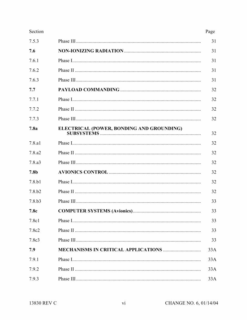
Section Page
753 Phase III 31
76 NON-IONIZING RADIATION 31
761 Phase I 31
762 Phase II 31
763 Phase III 31
77 PAYLOAD COMMANDING 32
771 Phase I 32
772 Phase II 32
773 Phase III 32
78a ELECTRICAL (POWER BONDING AND GROUNDING)SUBSYSTEMS 32
78a1 Phase I 32
78a2 Phase II 32
78a3 Phase III 32
78b AVIONICS CONTROL 32
78b1 Phase I 32
78b2 Phase II 32
78b3 Phase III 33
78c COMPUTER SYSTEMS (Avionics) 33
78c1 Phase I 33
78c2 Phase II 33
78c3 Phase III 33
79 MECHANISMS IN CRITICAL APPLICATIONS 33A
791 Phase I 33A
792 Phase II 33A
793 Phase III 33A
13830 REV C vi CHANGE NO 6 011404
Section Page
710 SOLID ROCKET MOTORS 33A
7101 Phase I 33A
7102 Phase II 33B
7103 Phase III 33B
711 BATTERIES 33B
7111 Phase I 33B
7112 Phase II 33B
7113 Phase III 33C
712 FLUID PROPULSION SYSTEMS 33C
7121 Phase I 33C
7122 Phase II 33D
7123 Phase III 33E
713 SEALED CONTAINERS (STRUCTURES) 33E
7131 Phase I 33E
7132 Phase II 33F
7132 Phase III 33F
8 VARIATIONS OF THE SAFETY REVIEW PROCESS 34
81 VARIATIONS FOR INTEGRATED MULTIPAYLOAD CARGO COMPLEMENTS 34
82 VARIATIONS FOR ISS PAYLOADS 34
821 On-orbit Reconfigured Payloads 34
822 Payloads Returning to Earth 35
9 REFLOWN AND SERIES PAYLOAD HARDWARE 36
10 PAYLOAD SAFETY NONCOMPLIANCE REPORT 38
101 NCR SUBMITTAL 38
13830 REV C vii CHANGE NO 6 011404
Section Page
102 TYPES OF SAFETY NCRs 38
1021 Waivers 38
1022 Deviations 38
11 LIST OF FORMS 39
111 JSC FORMS 39
112 KSC FORMS 39
12 APPLICABLE DOCUMENTS 40
APPENDIX A DOCUMENT MATRIX A-1
APPENDIX B ACRONYM LIST B-1
13830 REV C viii CHANGE NO 6 011404
SECTION 1 INTRODUCTION
Implementation of the payload safety process is the joint responsibility of the Payload Organization (PO) the flight operator Lyndon B Johnson Space Center (JSC) and the launchlanding site operator John F Kennedy Space Center (KSC)
The International Space Station (ISS) and Space Shuttle Program (SSP) safety policies and requirements for ISS and Shuttle payloads are specified in the current version of NSTS 17007ldquoSafety Policy and Requirements for Payloads Using the Space Transportation Systemrdquo and the current version of the NSTS 17007 ISS Addendum ldquoSafety Policy and Requirements for Payloads Using the International Space Stationrdquo In addition unique ground safety policies and requirements are specified in the current version of 45 SPW HB S-100KHB 17007 ldquoSpace Shuttle Payload Ground Safety Handbookrdquo These documents require the PO to conduct asystematic safety analysis and to document and submit a Safety Data Package (SDP) in support of safety reviews to be conducted by the flight operator (JSC) and the launchlanding site operator (KSC)
National Aeronautics and Space Administration (NASA) Headquarters has assigned the responsibility to review submitted payload safety documentation to the Space Shuttle and Space Station Program Directors at JSC and the Director of Safety and Mission Assurance at KSC The JSC Payload Safety Review Panel (PSRP) will assess the payload design and flight operations the KSC Ground Safety Review Panel (GSRP) will assess the Ground Support Equipment (GSE) design and ground operations These two panels were formed to accomplishthe following
bull Assure that PO interpretation of the safety requirements is consistent with NASA payload safety policy
bull Conduct safety reviews as appropriate during the development of the payload associated GSE and related operations
bull Evaluate hazard analyses and Noncompliance Reports (NCRs) bull Negotiate the resolution of safety issues involving design and operation to ensure compliance
with all applicable safety requirements bull Assess payload design features that have been implemented for controlling identified hazards
and the verification approach that confirms intended system performance
13830 REV C 1 CHANGE NO 6 011404
SECTION 2 PURPOSE
The purpose of this document is to define the payload safety review process in order to assist the ShuttleISS POs in documenting compliance with the payload requirements documents specified in section 1 Specifically this document accomplishes the following
bull Defines the safety reviews necessary to comply with the system safety requirements that are applicable to payload design flight operations GSE design and ground operations for both ISS and Space Shuttle
bull Identifies the required content of the SDP bull Describes preparation for and conduct of the safety review bull Establishes the timeline for data submittal and establishes the depth of detail required for the
various submittals bull Explains safety review process variations bull Defines the payload seriesreflight review process
13830 REV C 2 CHANGE NO 6 011404
SECTION 3 SCOPE
Data submittal requirements included herein apply to hardware being submitted to both the PSRP and the GSRP unless specified otherwise This document outlines the minimum data submittal requirements the PSRP and the GSRP reserve the right to request additional data as deemed necessary to support safety documentation
The objective of the safety review process is to review the payload GSE and operations for adequate safety implementation The mission success and any scientific objectives of the payload are the responsibility of the PO and are beyond the scope of this document and process
This document does not establish design requirements
31 APPLICABLE HARDWARE
This document applies but is not limited to the following payload hardware that fliesoperates on the Space Shuttle andor ISS during any mission phase (prelaunch launch ascent on-orbit entry landing or postlanding)
bull New Payload Hardware bull Existing (reflown and series) Payload Hardware bull Hardware Associated with Developmental Test Objectives (DTOs) Detailed Supplemental
Objectives (DSOs) Risk Mitigation Experiments (RMEs) Space Medicine Program (SMP) and Human Exploration and Development of Space Technology Demonstrations (HTDs) Experiment Hardware
The document also applies but is not limited to the following payload-related hardware
bull Government-Furnished Equipment (GFE) bull Airborne Support Equipment (ASE) bull GSE
32 EXPORT CONTROL
The PSRP complies with the United States export control laws and regulations as established by the US Department of Commerce in the Export Administration Regulations (EAR) and the US Department of State in the International Traffic in Arms Regulations (ITAR) The PSRP also complies with the Space Shuttle Programrsquos export control policy in NSTS 07700 Volume V and the ISSPrsquos export control policy in SSP 50223
13830 REV C 3 CHANGE NO 6 011404
Export control factors significantly into two areas of the payload safety review process
bull Distribution of Payload Data
bull Conduct of Safety Reviews
The PSRP Executive Secretary serves as the primary exporter of payload data to the ISS International Partners (IPs) and other foreign persons in support of the payload safety review process Payload data includes safety data packages hazard reports safety review presentation materials and other payload related information Specific export control data submittalrequirements for payload organizations are listed in section 4315 of this document
The PSRP Executive Secretary takes special precautions when conducting safety reviews for payloads under export control restrictions These precautions may include restricting attendance limiting presentation materials posting signs or conducting the review in a secure facility
13830 REV C 3A CHANGE NO 6 011404
SECTION 4 RESPONSIBILITIES OF THE PAYLOAD ORGANIZATION
The PO is responsible for assuring the safety of its payload and for complying with the safety requirements contained in the technical requirements documents cited in section 1 To this end the PO must accomplish the following
bull Perform a Safety Analysis bull Identify Hazards bull Document Compliance with the Safety Requirements bull Present the Documentation to the PSRPGSRP
41 SAFETY ANALYSIS
To meet the requirements of the current version of NSTS 17007 and NSTS 17007 ISS Addendum paragraph 301 the PO shall perform a safety analysis of the payload and GSE The analysis shall consider hardware design verification testing and flightground operations The safety analysis shall begin during the payload concept phase and shall be refined and expanded as the design matures For situations in which payload hardware will be installed orreconfigured on-orbit or in which the payload will be on-orbit for an extended time safety analyses shall consider the necessity of on-orbit verificationreverification of hazard controls
411 Level of Analysis
In order to identify the hazards applicable to a payload the PO shall conduct safety analyses both at the system and subsystem levels Each system and subsystem shall be evaluated to determinethe applicability of each technical safety requirement
Selection of subsystem groupings varies and any convenient grouping may be used The following is a suggested list of subsystems biomedical caution and warning cryogenic electrical environmental control human factors hydraulics materials mechanical opticalpressure systems propulsion pyrotechnics radiation and structures
For hardware developed for or provided to the PO the PO shall
bull Obtain the appropriate safety data from the supplier or conduct an independent safety analysis
bull Conduct a safety analysis of the interfaces between the subject hardware and other elements
412 Analysis Techniques
Depending on the complexity of the payload the PO should use established analytical techniques (eg preliminary hazard sneak circuit fault tree operational hazard and failure modes and effects analyses) to obtain the data necessary to complete present and support payload hazard reports
13830 REV C 4 CHANGE NO 6 011404
413 Safety Verifications for Payloads with Catastrophic Hazard Potential (Flight Only)
The current version of NSTSISS 18798 specifies data requirements to document the verification program for payload systemssubsystems that have catastrophic hazard potential An excerpt from this document is included below for convenience
Table 4-1 - NSTSISS 18798
All payload systems having catastrophic hazard potential for the orbiter or crew as a result of operations in or near the orbiter must use hardware and procedures that have been subjected to a rigorous verification program Verification programs normally require testing to verify adequate performance margins under all environmentalconditions (qualification testing) as well as demonstrating intended system performance on flight hardware Comprehensive system-level testing on payload flight hardware supported by qualification test on protoflight or flight type hardware are the preferred verification methods It is essential that payload system performance be verified from the input stimuli to the end function
Safety-critical system performance that cannot be verified by test shall be verified by independent parties using dissimilar analysis techniques whenever possible Single party analytical efforts can be used to verify performance only when the methodology is widely accepted and conservative margins are applied to the results
The payload organization must focus its attention to all parts of the payload verification program and orbiter interface verification activities to assure that the sub-elements of the total verification program are integrated into a comprehensive system verification effort that confirms the intended system performance When the use of ground test equipment(apparatus) is required to replace flight hardware functions verification methods shall be developed by engineering personnel independent from those designing the flight systemTest requirements procedures and test apparatus shall be derived from intended functional requirements rather than from the design and all items must be maintained under strict configuration control The payload organization is responsible for developing and presenting sufficient data to the PSRP [GSRP] to substantiate that the test requirements procedures and test apparatus will provide an adequate simulation in substitution for the end function
42 HAZARD IDENTIFICATION
The primary objectives of the safety review process are to identify the potential hazards applicable to a payload including its flight GSE and ground operations and to assure that the hazard controls and verifications (including on-orbit verificationreverification of hazard controls where applicable) are adequate and in compliance with the safety requirements To assist the PO in accomplishing these objectives appropriate safety terminology has been defined in the current version of NSTS 17007
Although not exhaustive the following is a list of some previously identified flight hazard groups that have been used on hazard reports collision contamination corrosion electrical shock explosion fire injury and illness loss of orbiter entry capability and inability to egress
13830 REV C 5 CHANGE NO 6 011404
The following are basic hazard groups applicable to ground operations structural failure of support structures and handling equipment collision during handling inadvertent release ofcorrosive toxic flammable or cryogenic fluids loss of habitablebreathable atmosphere inadvertent activation of ordnance devices ignition of flammable atmospherematerial electrical shockburns personnel exposure to excessive levels of ionizing or nonionizing radiation use of hazardousincompatible GSE materials inadvertent deployment of appendages working under suspended loads and rupture of composite epoxy overwrapped pressure vessels
43 DOCUMENTATION OF COMPLIANCE WITH THE SAFETY REQUIREMENTS
The safety analysis results shall be documented in the SDP which includes applicable payload hazard report forms (JSC Form 542B and JSC Form 1230) and presented to both the JSC PSRPand the KSC GSRP as described in this document Guidelines for completing the flight hazardreport forms and preparing the SDPs are found in JSC 26943 ldquoGuidelines for the Preparation of Payload Flight Safety Data Packages and Hazard Reports for Payloads Using the Space Shuttlerdquo current issue
For SDP preparation the PO is responsible for using the current version of all applicable forms and safety documentation The PO may verify current formsdocuments by contacting theExecutive Secretary to the PSRP or the Chairman of the GSRP These forms are listed in section 11
431 Data Submittals
Although there will be some duplication of material contained in data submittals prepared for PSRP and GSRP reviews each package serves a different purpose and must stand alone
Data submittals which may include SDPs and other supporting information (eg action item responses) should identify the flight on which the payload is manifested (if known) and be formally submitted in English to the Executive Secretary PSRP or the Executive Secretariat GSRP Data should be formally transmitted under the signature of the Program Manager
Safety review meetings are scheduled to be held approximately 45 calendar days after receipt of an acceptable SDP (ie an SDP that satisfies all the requirements in this document)
The SDP will be made available to the PSRPGSRP members and various other NASAcontractor technical and administrative personnel who support the Panels For ISS payloads this may include International Partner representatives to the PSRP
Payload safety data must be submitted electronically via the Internet using the Payload Safety Data Management System (DMS) located at the following URL
httppsrpjscnasagov
The DMS System Administrator (tel 281-483-9078) can provide information on acceptable software applications electronic addresses detailed login instructions and system procedures POs may also access the DMS via a hyperlink at the top of the Payload Safety homepage located at the following URL
13830 REV C 6 CHANGE NO 6 011404
httpwwwsrqajscnasagovpce
POs must obtain approval from the PSRP Executive Secretary or Executive Secretariat GSRP to submit flight or ground safety data respectively by alternate means or to submit supplementary data in hard copy format Hard copy submittals must be single-sided and sequentially paginated from the cover sheet to the last page of the package
Once the SDP has been electronically submitted the PO must send the transmittal lettersdocument signature pages and signed original Hazard Reports (HRs) to the appropriate Panel contact
Executive Secretary PSRPNASA Lyndon B Johnson Space Center
Mail Code NC4 2101 NASA Road 1
Houston TX 77058-3696
Executive Secretariat GSRP NASA John B Kennedy Space Center
Mail Code UB-F3 Kennedy Space Center FL 32899-0001
13830 REV C 6A CHANGE NO 6 011404
4311 Submittal of Proprietary Data
If proprietary data are submitted in the SDP the transmittal letter must include the following statement
This payload safety data package contains proprietary data on the following pages [listthe appropriate page numbers] [Insert name of the payload organization] acknowledges awareness and acceptance of the GSRP and the PSRPrsquos policies and methods of processing proprietary data [Insert name of the payload organization] also will provideany additional protective measures it deems necessary over and above that provided by the panels during meetings
The transmittal letter and the first page of the SDP must identify the specific pages that contain proprietary information Insert the word ldquoPROPRIETARYrdquo at the top and bottom of each pagethat contains proprietary data The word ldquoPROPRIETARYrdquo shall be in all capital letters in alarge font size and style that is easily discernible from the rest of the text
In addition to the proper submittal of proprietary information the PO should be aware of the following while attending PSRPGSRP safety reviews Technical Interchange Meetings (TIMs) and action item closure meetings
bull PSRPGSRP meetings are not conducted in secure facilities Thus when it is necessary torecess meetings (eg lunch and breaks) the POs will be responsible for protecting any proprietary data distributed during the meeting (other than that logged and distributed byNASA as part of the SDP)
bull If any proprietary data are to be presented or discussed during the meeting prior to the meeting the PO will notify the PSRP Executive SecretaryGSRP Chairman who will then make arrangements to monitor attendance close the doors and post a sign noting that accessto the meeting is controlled
bull The PO will be responsible for retrieval and disposition of any proprietary material distributed at the meeting (other than that logged and distributed by NASA as part of the SDP) with the exception that two copies of proprietary material distributed by the PO at the meeting will be retained by the PSRPGSRP in a protected file
When the PSRPGSRP receives proprietary data included in the SDPs such data will be handledin a manner that will protect the interests of the PO These procedures include trackingdistributed materials protecting files and restricting reproduction In order to exercise reasonable care in protecting proprietary data in connection with the payload safety review process NASA will ensure that proprietary data are distributed only to persons who have a needto review such data in support of panel functions Furthermore distributed data that is returned to the PSRP Executive SecretaryGSRP Chairman after use will be destroyed via the NASAsecure disposal process
13830 REV C 7 CHANGE NO 6 011404
The protection of material marked ldquoPROPRIETARYrdquo creates an added burden on thePSRPGSRP review support system so the PO should mark only those items that are proprietary The PO should coordinate with the PSRP Executive SecretaryGSRP Chairman to explore such alternatives as providing the proprietary material in a separate package when it is a very small portion of the overall SDP If a separate proprietary briefing package (not containedin the SDP) is to be presented to the PSRPGSRP during the review the PO shall provide at least20 copies of such material for distribution at the review
If the PO discovers that some portion of the SDP marked ldquoPROPRIETARYrdquo is no longerconsidered such the PO must inform the PSRP Executive Secretary andor the GSRP Chairmanin writing
4312 Submittal of Copyrighted Data
Payload organizations are hereby informed that payload documentation submitted to NASA must be reproduced and distributed to the members of the PSRPGSRP and to associated technicalsupport personnel Accordingly copyrighted data shall not be included in the submitteddocumentation unless the PO 1) identifies such copyrighted data and 2) grants to theGovernment or acquires on behalf of the Government a license to reproduce and distribute the data to these necessary recipients
4313 Submittal of Translated Data
For all documents submitted by the PO to the PSRPGSRP that have been translated intoEnglish the English translation shall be the official document
4314 Submittal of Toxicological Data for SSP and ISS Payloads (Flight Only)
The ShuttleISS payload safety review process requires biomedical safety assessments of potentially hazardous materials such as chemicals microorganisms and radioisotopes In order for these assessments to be available for the safety reviews the JSC Toxicology Group requires POs to submit test sample data substantially in advance of the safety reviews See JSC 27472 ldquoRequirements for Submission of Test Sample-Materials Data for Shuttle Payload Safety Evaluationsrdquo current issue for the timeline and data requirements for these early submittals The PO must attach both the data submitted to JSC Toxicology Group and the JSC response (when available) to the applicable hazard report that is a part of the SDP Should toxicology submittals involve proprietary data see section 4311
4315 Submittal of Export Control Data (Flight Only)
The export control data submittal requirements in sections 43151 and 43152 apply to USpayload organizations only IP payload organizations are not required to provide the US export control classification of their safety data packages In the event that an IP SDP requires a USexport control classification NASA export control resources will be used to classify the SDP
13830 REV C 8 CHANGE NO 6 011404
43151 ISS Payloads
Distribution of ISS payload safety data packages to the ISS IPs is a standard part of the payload safety review process
The PO must identify the export control classification of the SDP payload data in its transmittal letter The first page of the SDP must also identify the export control classification of the data
The PSRP Executive Secretary will not distribute an SDP with an unknown export controlclassification to the IPs Safety reviews may be delayed or cancelled for ISS payloads with unresolved export control issues
The POrsquos safety review presentation materials must have the same export control classification as the SDP submitted for review or a less restrictive export control classification
43152 Shuttle Payloads
Distribution of Shuttle payload safety data packages to the ISS IPs is not a standard part of the payload safety review process
Shuttle payload safety data packages are not distributed to the IPs unless the PSRP identifies a specific need to do so If a need is identified the PSRP Executive Secretary will work with the PO and the SSPrsquos export control resources to obtain the export control classification of the SDP
The PO may include the export control classification of the SDP payload data in its transmittalletter and on the first page of the SDP if the classification is known prior to SDP submittal
432 Hazard Reports
The purpose of the hazard reports is to document the POrsquos safety assessment in a manner that reflects how the payload design demonstrates compliance with the safety requirements The hazard reports are used as a method to systematically assess compliance with the safety requirements
The flight SDP submittal must contain all flight hazard reports the ground SDP submittal mustcontain all ground hazard reports Each hazard report must be signed and dated by the payloadprogram manager prior to submittal Hazard reports shall be prepared on JSC Form 542B JSCForm 542B-1 or JSC Form 1230 (see section 11) or an equivalent form that contains all information required on the JSC forms Section 7 organized by area of design identifies minimum support data for flight hazard reports JSC 26943 contains guidelines for preparingpayload flight hazard reports
13830 REV C 8A CHANGE NO 6 011404
Following any technical discussion the PSRPGSRP Chairman will provide a disposition for each hazard report This disposition may take one of the following forms 1) approved aswritten 2) approved with modification 3) approved with an action to be performed by the PO andor PSRPGSRP and 4) not approved
The PO is responsible for retaining and maintaining the original hazard reports after approval
44 SAFETY REVIEW PRESENTATION
The PO should be prepared to present information submitted in the SDP to the appropriate safety panel during scheduled reviews (see sections 611 and 612) During reviews the PO shouldprovide briefing chart handouts sufficient for the number of people expected to attend the review
13830 REV C 9 CHANGE NO 6 011404
SECTION 5 SAFETY REVIEW OVERVIEW
51 LOCATION
Safety reviews for payload design and flight operations are usually conducted at JSC The safetyreviews for GSE design and ground operations will normally be conducted at KSC The PO shall coordinate the timing of the PSRP reviews with the PSRP Executive Secretary The PO shall coordinate the timing and location of the GSRP reviews with the GSRP Chairman
52 INITIAL CONTACT MEETING
The PO may receive initial contact safety briefings by the JSC and KSC safety representatives The JSC briefing normally held during the first integration meeting at JSC should be scheduledby contacting the Payload Integration Manager (PIM) at JSC For ISS payloads contact the ISSPIM The KSC briefing is usually held in conjunction with the first Ground Operations Working Group (GOWG) meeting which is scheduled through the Launch Site Support Manager Integration Manager (LSIM) at KSC
The briefing includes an overview of the technical and system safety requirements to be met by the PO plus instructions for conducting the safety reviews The PO should provide a schedule ofpayload milestones and request a phase 0 or phase I safety review when the payload design concept has been developed
53 TYPES OF MEETINGS
Safety reviews may take place in person via teleconference or by correspondence Review meetings may be formal or out-of-board as deemed appropriate by the Panel Chairman
bull Formal Meeting Formal meetings constitute a gathering of the safety review panel representatives of the PO and the appropriate supporting technical staff
bull Out-of-Board Meeting Out-of-board meetings do not require the full safety panel Attendees may include the Panel Chairman Safety representative(s) representatives of the PO and others necessary to address the issues that may be involved
bull Safety TIM The review panel andor associated technical staff may convene upon request in order to assist in interpreting safety requirements or to coordinate safety analysesissues prior to safety reviews Requests for flight safety TIMs should be coordinated with the PSRP Executive Secretary Requests for Ground Safety TIMs should be coordinated with the GSRP Chairman Material to be addressed during the TIM should be provided 14 calendardays prior to the TIM
bull Splinter Meetings Splinter meetings may be held concurrently with a safety review to discuss detailed technical concerns
13830 REV C 10 CHANGE NO 6 011404
54 PAYLOAD CATEGORIES
Traditional payload safety compliance assessment is accomplished using a phased safety review process (phases 0 I II III) that corresponds to the hardware conceptual preliminary and critical design review phases and verificationvalidation of the payload (see section 6) Successful completion of each safety phase is documented by SDPHR submittals to and approval by the PSRPGSRP
To streamline this process the PSRP has implemented procedures and data requirements to minimize formal PSRP review time for payloads with routine hazardsstandard controlsverifications This allows the PSRP to concentrate review time on payload systems withthe highest hazard potential ldquomust-workrdquo functions andor nonstandard controls and verification methods POs may document routine hazards and standard controls and verifications on the JSC Form 1230 ldquoFlight Payload Standardized Hazard Control Reportrdquo
Based on the phase I SDP new payloads are categorized by the PSRP into one of three categories of complexity (basic intermediate or complex) with respect to hazard potential as shown in Table 5-1 below The review process is then tailored to the complexity of the payload design and adequacy of documentation In addition the process permits all payloads to document standard hazards that have standard controls and verifications on JSC Form 1230 which may be approved by the PSRP without a formal PSRP meeting Details concerning basicand intermediate categories are contained in sections 541 and 542 respectively Complexpayloads use the review process detailed in section 6 Reflown and series payloads use thereview process outlined in section 9
Table 5-1 - PAYLOAD CATEGORIES
PayloadCategory
Defined Hazards
Basic The only hazards identified are ldquostandardrdquo as specified on the JSC Form 1230 The appropriate hazard controls are found on JSC Form1230
Intermediate 1) The payload has ldquouniquerdquo hazards (ie hazards not found on the JSC Form 1230) but has controls and verification methods that have been historically accepted by the PSRPOR
2) The payload has ldquostandardrdquo hazards (ie hazards identified on the JSC Form 1230) but uses controls and verification methods other than those identified on the JSC Form 1230
Complex The payload has unique hazards with hazard controls that are
a Active ldquomust workrdquo functions such as electromechanical or pyrotechnic separation systems or actuatorsmechanisms providing structural load paths
OR b Nonstandard or have nonstandard verification methods that
depart from historically accepted techniquesOR c Operationally complex requiring flight or ground personnel
intervention to assist in controlling the hazard
13830 REV C 11 CHANGE NO 6 011404
If after a payload category has been assigned the PO a) identifies previously undefined hazards or b) implements design changes that may create new hazards the PO must submit a revisedSDP which may result in a reclassification of the payload category
541 Review Process for Basic Payloads (Flight Only)
Basic payloads (see Table 5-1 above) have a very low level of complexity which may allow the payload to complete the safety process out of board However the PO will submit an SDP that will document the applicable hazards controls and verifications Submittal will follow the standard procedure detailed in section 431 and approval may be obtained without a meeting The following data are required for the simplified SDP for hardware design and flight operations
bull Brief description of the hardware design and flight operations with schematics and block diagrams as appropriate
bull Summary of the safety analysis results that documents compliance with the design verification and applicable on-orbit verificationreverification requirements for the identified standard hazards
bull Documentation of all applicable hazards controls and verifications on hazard report(s) (eg JSC Form 1230Form 542)
bull Certificate of Payload Safety Compliance (JSC Form 1114A) signed by the ProgramManager
542 Review Process for Intermediate Payloads (Flight Only)
In addition to the standard hazards found in Basic payloads the Intermediate payload has unique hazards that have standard controls and verification methods (including applicable on-orbit verificationsreverifications) that have been historically accepted by the PSRP Intermediate category payloads should require one or two reviews of the unique hazards but the basic hazards may be addressed on a Form 1230 and approved out of board The PSRP will determine the need for a second review for unique hazards at the completion of the first review The determination will be based primarily upon the completeness and quality of the unique hazard reports Requirements for SDP submittal are the same as those stated in section 431
55 SCHEDULE OF REVIEWSPHASES
The schedule for formal phase 0 I and II payload safety reviews generally relates to the payload development schedule Phase 0 is held during the concept phase or at the start of payload design Phase I is near the Preliminary Design Review (PDR) phase II is near the Critical Design Review (CDR) The PO should set the review schedule to obtain maximum benefit to payloaddevelopment based on the results of the safety reviews
ISS payloads may include multiple major systems or components each working to a uniqueschedule These may be individually baselined and categorized (see section 54) which allows them to progress through the payload safety process in accordance with their own schedule (see section 82)
13830 REV C 12 CHANGE NO 6 011404
Phase III is associated with completion of payload safety verifications andor the start of ground processing When establishing a timeline for phase III the PO should allow enough time to closepotential issues that may result from a phase III review The timing and completion of the phase III review and safety certification are critical to the launch schedule The flight and ground phaseIII completion requirements restated below are in the current version of NSTS 17007 and NSTS 17007 ISS Addendum and apply to all payloads
The JSC and KSC Phase III safety review and ground safety certification must be completed 30 days prior to delivery of the payload ASE and GSE to the launch sitehellip
If any verification items remain open on the flight hazard reports the PO must provide rationale to support the safety of starting ground processing with these items open The rationale is to be submitted to both the PSRP and GSRP The PSRP will review the rationale and provideconcurrence to the GSRP
To schedule KSC Ground safety reviews contact the GSRP Chairman to schedule JSC Flight safety reviews contact the PSRP Executive Secretary (see section 431)
56 SAFETY REVIEW COMPLETION
561 Documentation of Phase Completion
During a formal meeting the Panel Chairman will make an official announcement that the safety phase is complete or incomplete (open) This announcement will be recorded and distributed bythe PSRPGSRP in the official meeting minutes Incomplete phases are usually attributable to overdueopen action items or unsigned (open) hazard reports The PSRPGSRP will issue officialcorrespondence to document closure of open action itemssignature of open hazard reports thatoccurs after the phase review The correspondence that closes the last open action itemhazardreport for that phase will include a statement that the safety phase is considered complete
For out-of-board reviews safety review process completion will be documented by formal correspondence
562 Completion Criteria for Phase I II and III
Successful completion of phase I and II reviews is accomplished by obtaining approval (Panel Chairmanrsquos signature) of hazard reports at the appropriate phase level and closure of applicable phase III action items
After submission of all required data the criteria for successful completion of the safety review process at the phase III level for both flight and ground reviews are as follows
bull All payload hazard reports are signed by the payload Program Manager and the Panel Chairman at the phase III level
bull All NCRs are approved bull Safety review action items are formally closed in the safety review meeting minutes or
documented closed in separate correspondence bull A signed Certificate of Ground Payload Safety Compliance provided to the GSRP (for phase
III ground safety)
13830 REV C 13 CHANGE NO 6 011404
Approval of the phase III safety data by the PSRP and GSRP is with the understanding that the data represent the actual design and operations of the payload Should safety issues arise after the safety process is complete the safety panels reserve the right to request additional data deemed necessary to reassess the payload
563 Completion Criteria for SeriesReflight
The criteria for successful completion of a series or reflight safety review is that all data required by section 9 Reflown and Series Payload Hardware have been submitted and approved
57 POST PHASE III SAFETY ACTIVITY
571 Certificate of Flight Payload Safety Compliance
The PO must present a signed Certificate of flight Payload Safety Compliance to the PSRP Executive Secretary no later than 10 days prior to the Flight Readiness Review (FRR)
572 Configuration Control
When changes to the design configuration or operations of the payload are required subsequent to phase III the PO shall assess those changes for possible safety implications including the effect on all interfaces The assessment shall be forwarded to the PSRPGSRP for review andapproval If the change has ground safety implications it must be reviewed with the KSC panel prior to proceeding with ground processing New or revised hazard reports and support datashall be prepared where applicable and submitted for approval as indicated in section 431 The need for delta phase III safety reviews will be determined by the PSRPGSRP Chairman Satisfactory completion of these activities is mandatory prior to the start of affected ground activities or launch
Any test failures anomalies or accidents involving payload flight hardware or software that occurs between the completion of phase III and launch must be promptly reported to the PSRPGSRP Safety impacts if any should be identified
573 Verification Tracking Log
Open verification items must be tracked on a flight or ground safety Verification Tracking Log (VTL) (see section 11)
bull Flight Safety From Phase III until L-60 days the PO shall update and provide the VTL to the PSRP Executive Secretary once a month From L-60 days until launch the PO shall provide a weekly update to the VTL All VTL open items must be closed no later than 4PM Central time on the last business day prior to launch Items that cannot be closed at this time will require the transmission of a facsimile closing the open VTL items to the Mission Evaluation Room (MER) at NASA JSC no later than L-6 hours Contact the PSRP Executive Secretary for MER delivery instructions
bull Ground Safety The initial submittal of the ground safety VTL is required with the phase III ground SDP Following the completion of the phase III review the ground safety VTL shall be updated monthly prior to hardware arrival at KSC If there are open flight verifications
13830 REV C 14 CHANGE NO 6 011404
that are constraints to ground processing the PO must also include those items of the flight VTL After the delivery of the payload ASE or GSE to the launch site the safety VTL(s) shall be updated at least weekly More frequent updates to the safety VTL(s) may be required if the open items must be closed to allow work to continue
574 Documentation of Safety Process Completion
Final flight safety approval is documented by the PSRP Chairmanrsquos signature on the Certificateof Flight Readiness (CoFR) for the planned flight
Final ground safety approval is documented by a letter from the KSC Director Safety Assurance to the KSC Director Customer Service Space Station and Shuttle Payloads Processing statingthat the Ground Safety Review Process has been completed and the payload may begin ground processing
13830 REV C 15 CHANGE NO 6 011404
SECTION 6 SAFETY PROCESS
61 GENERAL
611 Preparation
In preparation for a phase safety review the PO will submit an SDP as indicated in section 431 If phase reviews are combined (eg a phase III review) the SDP shall include the datarequirements that apply to all the appropriate phases The depth and number of the plannedreviews are dependent on the complexity technical maturity and hazard potential of the payload and may be modified by the Panel Chairman in conjunction with the PO
The PO should provide sufficient technical support personnel to answer questions posed by the PSRPGSRP in support of the agenda items
Listed below are general agenda topics for safety review meetings These insure that the safety review meetings proceed smoothly and contain the necessary information to facilitate the review
612 General Meeting Agenda Guidelines
The PO should coordinate all meeting agenda with the PSRP Executive Secretary or the GSRP Chairman prior to the safety review meeting and provide the final agenda in advance The fundamental elements of all Safety Review Meeting Agenda are as follows
a Introduction of the Meeting and Participants by the JSC Safety Reliability and Quality Assurance (SRampQA) Payload Safety Engineer (PSE)
b Opening Remarks by Chairman and the Payload Program Manager
c Discussion of Pre-Review Activity Led by the PSE
d Program-level Overview (including areas of responsibility)
e Program Milestone Schedule Provide the Program Milestone Schedule includingbut not limited to
(1) design stages and reviews
(2) hardwaresoftware build status
(3) testing and verification activities
(4) delivery integration and launch activities and
(5) safety review dates
f Mission Objectives including overview of mission objectives and general criteria for a successful mission
13830 REV C 16 CHANGE NO 6 011404
g SystemSubsystem Technical Presentation Overview including enough information to allow the PSRPGSRP to gain a general technical understanding of the systemsinvolved in the payload operations Highlight any design changes since the previous safety reviews
h Operations Overview describing planned operations and known contingencies Plan to discuss detailed operations that relate to payload safety in conjunction with the appropriate hazard report presentation Highlight any operations changes made tothe operations that impact the safety of the payload since the previous review
i Safety Assessment Summary including safety assessments performed to identify hazards any failures or anomalies that occurred after development testing and the corrective actions Present responses to agreements and formal action items including a summary of open action items and associated plans for closure Provide sufficient information to demonstrate that a comprehensive hazard analysis has been performed Provide an overview of hazards and how they relate to the hazard reports and discuss safety-related items that are not reflected in the hazard reports
j Phase-specific Topics Additional phase-specific topics for the agenda should be drawn from the data that are required to be included in the SDP for that phase (see sections 621 631 641 and 651) If not included as one of the general agendatopics these data should be addressed as separate agenda items
k Hazard Report Presentation Unless otherwise agreed to by the PSRPGSRPpresent all hazard reports in full associated noncompliancereportswaiversdeviations previously assigned action itemsagreements that involved modification of hazard reports and associated action itemagreement responses
l Action Item Review Both the PO and the PSRPGSRP will review and agree toactions and due dates assigned during the course of the safety review to ensure that there are no misunderstandings These action items will be printed and signed during the review
m Closing Comments Payload Program Manager and Panel
62 PHASE 0 SAFETY REVIEW
The optional phase 0 safety review is provided as a service to the PO The objectives of the meeting are to
bull Assist the PO in identifying hazards hazard causes and applicable safety requirements early in the development of the payload
bull Adequately describe the hazard potentialbull Answer questions regarding the interpretation of the safety requirements or the
implementation procedures of this documentbull Provide guidance to the PO for preparing the safety data required for subsequent safety
reviews
13830 REV C 17 CHANGE NO 6 011404
621 Phase 0 Data Requirements
The following data are required for the phase 0 SDP and must be submitted as stated in paragraph 431
a For payload design and flight operations
(1) Conceptual payload description (including subsystems) and missionscenario
(2) Description of safety-critical subsystems and their operations
(3) Flight hazard reports (JSC Form 542BForm 1230)
b For GSE design and ground operations
(1) Conceptual payload description and brief mission scenario
(2) Conceptual GSE description and operations and description of payload design that is safety critical during ground operations
(3) Ground operations scenario
(4) Ground hazard reports (JSC Form 542B)
The description of the payload and its operation must be of sufficient detail to permit identification of all subsystems that may create hazards Emphasis should be given to thosesubsystems that store transfer or release energy The descriptions of the safety-critical subsystems must be of sufficient detail to identify the hazards in terms consistent with the conceptual design In addition the PO shall address tentative plans for any flight operation (eg extravehicular activity reverification of hazard controls) or ground operation that would require personnel certification to perform hazardous procedures
622 Phase 0 Hazard Reports
The purpose of a phase 0 hazard report is to document and scope the specific hazards identified It is intended to be a working document for discussion and critique at the phase 0 safety review and will not require signatures A hazard report must be prepared for each unique hazardidentified in the safety analysis The hazards contained on the phase 0 hazard report must reflect the payload conceptual design and operations existing at the time of the phase 0 review For phase 0 the PO may identify hazard controls verification methods or status of verifications
63 PHASE I SAFETY REVIEW
The purpose of the phase I safety review is to obtain PSRPGSRP approval of the updated safety analysis that reflects the preliminary design and operations scenario of the payload At this pointthe PO shall present a refined safety analysis that identifies all hazards and hazard causes inherent in the preliminary design evaluates all hazards for means of eliminating reducing or controlling the risk and establishes preliminary safety verification and on-orbit verificationreverification methods The PO shall provide a preliminary identification of the payload interfaces and of the hazards presented by these interfaces
13830 REV C 18 CHANGE NO 6 011404
631 Phase I Data Requirements
The following data are required for the phase I SDP and must be submitted as stated in paragraph 431
a For payload design and flight operations
(1) Updated payload description (including subsystems) and mission scenario
(2) Updated descriptions of safety-critical subsystems and their operations including schematics and block diagrams with safety features inhibits and controls identified Identify any safety-critical subsystems that are computer controlled and identify the functional architecture associated with that computer control
(3) Updated and additional flight hazard reports (eg JSC Form 542BJSC Form 1230) including appropriate support data (see section 7) For payloads thathave catastrophic hazard potential document the verification programoutlined in NSTSISS 18798
(4) A summary list (in the payload description) of orbiter- andor ISS program-provided critical services and an explanation (in the appropriate hazard reports) of the orbiter andor ISS services used to control andor monitorpayload hazards (NSTS 17007 and NSTS 17007 ISS Addendum current version)
(5) For ISS payloads a presentation of the Fire Detection and Suppression (FDS) implementation approach For sub-rack payloads the PO shall address the integrated system approach (using sub-rack services andor ISS services) to fully define the FDS implementation strategy In addition submit JSC Form 1428 to document methods and verifications used to detect and suppress a fire event for each payload volume
(6) Discussion of design features supporting verificationreverification of hazard controls on-orbit and associated constraints
(7) A tabulated list of tentative toxic materials and support data per JSC 27472(see section 4314)
(8) A list of all battery types their uses manufacturer and applications
(9) A preliminary description of all pyrotechnic devices and their functions
(10) Preliminary on-orbit maintenance safety assessment as outlined in NSTSISS 18798
b For GSE design and ground operations
(1) Updated payload description and brief mission scenario
13830 REV C 19 CHANGE NO 6 011404
(2) Updated descriptions of GSE payload subsystems that present a potential hazard during ground processing and their ground operations Schematics and block diagrams with safety features and inhibits identified should be included Design data for hazardous systems (pressure lifting etc) shall be summarized in a matrix Contact the GSRP Chairman for sample formats
(3) Updated ground operations scenario including postflight ground operationsat the primary alternate and contingency landing site The scenario should highlight unique payload requirements at the launch pad such as continuous power through a T-0 umbilical
13830 REV C 19A CHANGE NO 6 011404
(4) Updated ground hazard reports (JSC Form 542B) including appropriatesupport data
(5) Ordnance data required by the current version of KHB 17007 Appendix D
(6) Estimated KSC on-dock arrival date
632 Phase I Hazard Reports
The PO shall prepare phase I hazard reports for each hazard identified as a result of the safety analysis for the preliminary design and operations scenario of the payload Hazard reports shallbe added to or deleted from those agreed to during phase 0 to reflect the updated safety analysis Rationale for deleting a hazard agreed upon at phase 0 shall be presented during the phase I review
For phase I the PO shall identify hazard controls for each hazard cause identified at phase 0 A direct correlation between each hazard cause and the corresponding hazard control(s) must be clearly shown on the report Sufficient supporting information detailing each hazard control must be provided
Verifications should include the types of tests analyses inspections or procedures to be used to verify each hazard control including all orbiter- or ISS-provided services or interfaces both prelaunch and on-orbit A direct correlation between each verification method and the corresponding hazard control must be clearly shown on the report Each verification item should be independent and have a designator that allows for individual tracking of verification status
Manufacturingassembly proceduresprocesses that are critical in controlling hazards that cannot or will not be verified by subsequent inspection or test must be verified during the manufacturingassembly process An independent verifier as specified by the PO shall attest toproper completion of the procedureprocess Critical proceduresprocesses which require special monitored verification (Mandatory Inspection Points [MIPs]) shall be identified in preliminary fashion (NSTS 17007 and NSTS 17007 ISS Addendum current version)
If available the PO should provide a tentative schedule for completion of each verification taskand correlate with the integration schedule
64 PHASE II SAFETY REVIEW
The purpose of the phase II safety review is to obtain panel approval of the updated SDP that reflects the CDR-level design and operations scenario of the payload The phase II safety analysis identifies all hazards and hazard causes defines and documents implementation of a means for eliminating reducing or controlling the risks and documents finalized specific safety verification and on-orbit verificationreverification methods (test plans analysis and inspection requirements etc) Payload interfaces mission and ground operations procedures and timelines that were not addressed during the phase I safety review shall be assessed for safety hazards The payload interfaces to be assessed shall include those between the Shuttle andor ISS and the payload and among the various components that make up the payload (the spacecraft upper stages space platforms pallets experiments ASE ancillary flight equipment GSE KSC Facilities GFE etc) Newly identified hazards shall be documented in additional hazard reports For this review the PO should provide the estimated KSC on-dock arrival date
13830 REV C 20 CHANGE NO 6 011404
641 Phase II Data Requirements
The following data are required from the PO for phase II and must be submitted as stated in paragraph 431
a For payload design and flight operations
(1) Updated payload description (including subsystems) and mission scenario
(2) Updated descriptions of safety-critical subsystems and their operations including schematics and block diagrams with safety features and inhibits identified Provide electrical schematics that clearly identify the requirednumber of independent inhibits controls and monitoring provisions Present a summary of the test and analytical efforts required to verify the intended performance of all safety-critical hardware For a computer-based control system that is used to prevent criticalcatastrophic hazards provide the following datadescriptions bull Functional architecture bull Expected interactions bull Results of unexpected interactions bull Protections for common cause failures bull Development process for databases hardware software and
hardwaresoftware (3) Updated and additional flight hazard reports (eg JSC Form 542BJSC
Form 1230) including appropriate support data (see section 7) For payloads that have catastrophic hazard potential document the verification program outlined in NSTSISS 18798
(4) Updated summary list and explanation of orbiter- andor ISS-provided critical services
(5) For ISS payloads an update of the FDS implementation approach Include information on use of forced air flow wire derating circuit protection materials usage parameter monitoring (fan speeds temperatures currentetc) and responses to an out-of-limit condition and suppression approach For sub-rack payloads the PO shall address the integrated system approach (using sub-rack services andor ISS services) to fully define the FDS implementation strategy Updated JSC Form 1428 to reflect specific test (or analysis) procedures to be used along with the schedule for completion of FDS verification tests analyses or inspections
13830 REV C 21 CHANGE NO 6 011404
(6) Verification methods associated with hazard controls that require on-orbit verification andor reverification and the applicable approach (include rationale constraints and detailed methodology)
(7) An updated tabulated list of planned toxic materials and support data per JSC27472 (see section 4314) Updates should include changes in testmaterials changes in test conditions and any alternate test materials
(8) Updated list of all battery types their uses manufacturer and applications
(9) A list of all pyrotechnic devices their functions chemical composition critical components inspection plan verification plan and aging degradation evaluation plan
(10) List of hazard controls that require crew procedures andor training
(11) A record of test failures anomalies and accidents involving qualification or potential flight hardware Include a safety assessment for items which may affect safety
(12) The status of all action items assigned to the PO during phase I
(13) Detailed on-orbit maintenance safety assessment as outlined in NSTSISS 18798 Identify maintenance activities safe access areas and reverification of safety critical features
b For GSE design and ground operations
(1) Updated payload description and brief mission scenario
(2) Updated descriptions and matrices of the GSE the payload subsystems that present a potential hazard during ground processing and their ground operations Include updated schematics and block diagrams with safety features and inhibits identified Electrical schematics must show all payloadGSE grounding
(3) Updated ground operations scenario including postflight ground operations at the primary alternate and contingency landing sites
(4) Updated and additional ground hazard reports (JSC Form 542B) includingappropriate support data
(5) Updated ordnance data required by the current version of KHB 17007 Appendix D
(6) Updated KSC on-dock delivery date
(7) Specific engineering drawings and stress analyses of subsystems whenrequested by the GSRP Chairman
(8) A list of safety-related failures and mishaps that have occurred
13830 REV C 22 CHANGE NO 6 011404
(9) The status of all action items assigned to the PO during phase I
(10) A list of technical operating procedures that will be used at KSC with apreliminary designation as to which ones are considered hazardous
13830 REV C 22A CHANGE NO 6 011404
642 Phase II Hazard Reports
The PO shall prepare the phase II hazard reports by revising the phase I hazard reports to reflectthe completed payload design and flightground operating procedures If the payload designchanges from phase I to phase II so that a phase I hazard report may be deleted present a brief statement of rationale for deleting the report in the phase II SDP The GSRPPSRP willdisposition the hazard reports
Address all critical proceduresprocesses including the plan for verification Verifications shall refer to specific test (or analysis) procedures and summarize passfail criteria to be used Specifythe schedule for the completion of each specific verification test analysis or inspection
65 PHASE III SAFETY REVIEW
The purpose of the phase III safety review is to obtain PSRPGSRP approval of the SDP and safety compliance data that reflects the safety verification findings The focus of this review is to assess safety verification testing and analysis results If verifications critical for establishing the acceptability of the fundamental design of the payload for safety are not completed prior to the phase III review then subsequent reviews may be required prior to hazard report approval All verifications that are open at the time of the phase III SDP submittal must be included on the safety VTL Items listed on the VTL should be planned open work items such as groundprocessing at KSC
651 Phase III Data Requirements
The following data are required for the phase III SDP and must be submitted as stated in paragraph 431
a For payload design and flight operations
(1) Final as-built payload description (including subsystems) and mission scenario
(2) Updated descriptions that define the final configuration of the safety-critical subsystems and their operations including schematics and block diagramswith the as-built payload safety features and independent inhibits controls and monitoring provisions identified Address applicable features andconstraints relating to on-orbit verificationreverification of hazard controls
For a computer-based control system that is used to prevent criticalcatastrophic hazards provide verifications for the following bull Functional architecture bull Expected interactions bull Results of unexpected interactions bull Protections for common cause failures bull Flight article databases hardware software and hardwaresoftware
operate as designed
13830 REV C 23 CHANGE NO 6 011404
(3) Updated (and additional if required) flight hazard reports including support data that reflect the final configuration of the as-built payload and planned use For payloads that have catastrophic hazard potential document theverification program outlined in NSTSISS 18798
(4) Final summary list and explanation of orbiter- andor ISS-provided critical services
(5) For ISS payloads a finalized FDS implementation approach Include information on use of forced air flow wire derating circuit protectionmaterials usage parameter monitoring (fan speeds temperatures currentetc) and responses to an out-of-limit condition For sub-rack payloads the PO shall address the final integrated system approach (using sub-rack services andor ISS services) to fully define the FDS implementation strategy Final JSC Form 1428 to summarize the results of the completedtests analyses andor inspections and refer to particular test reports by document number title and date
(6) Updated (and additional if required) verification methods associated with hazard controls that require on-orbit verification andor reverification and the applicable approach (include rationale constraints and detailed methodology)
(7) A final tabulated list of toxic materials and support data per JSC 27472 (see section 4314) including additions and changes in test materials changes in test conditions and any alternate test materials
(8) A final list of all battery types their uses manufacturer and applications
(9) A final list of all pyrotechnic devices installed or to be installed on the payload The list will identify for each cartridge the function to be performed the part number the lot number and the serial number
(10) Updated list of hazard controls that require crew procedures and or training
(11) An updated record of test failures anomalies and accidents involving qualification or potential flight hadware or baselined flight software if the software is used for hazard control Include a safety assessment for items which may affect safety
(12) The status of all action items assigned to the PO through phase II
(13) Payload Flight Safety VTL (JSC Form 764)
13830 REV C 24 CHANGE NO 6 011404
(14) Identification of flight safety noncompliances Flight safety NCRs must be approved as either a waiver or a deviation before the phase III safety review can be completed A signed copy of each approved safety waiver andor deviation shall be included in the phase III SDP attached to the appropriate hazard report
(15) Finalupdated on-orbit maintenance safety assessment as outlined in NSTSISS 18798
b For GSE design and ground operations
(1) Final as-built payload description and brief mission scenario
(2) Updated descriptions and matrices defining the final configuration of the GSE the payload subsystems that are potentially hazardous during ground processing and their ground operations Include updated schematics andblock diagrams with the as-built safety features and inhibits identified
(3) Updated and finalized ground operations scenario including postflight ground operations at the primary alternate and contingency landing sites
(4) Updated and additional ground hazard reports including support data thatreflect the final configuration of the as-built GSE and planned payloadGSE use
13830 REV C 24A CHANGE NO 6 011404
(5) Updated and finalized ordnance data required by the current version of KHB 17007 Appendix D
(6) Updated and finalized KSC on-dock delivery date
(7) Specific engineering drawings and stress analyses of subsystems whenrequested by the GSRP Chairman
(8) A summary and safety assessment of all safety-related failures and accidents applicable to payload processing test and checkout Identify impact to theSpace Shuttle other payloads and facilities
(9) The status of all action items assigned to the PO through phase II
(10) Finalized list of technical operating procedures that will be used at KSC withthe hazardous procedures clearly identified The list shall also state the proposed first use of the procedure at KSC
(11) Verification that each payload flight system pressure vessel has a pressure vessel logbook that shows pressurization history fluid exposure and otherapplicable data This verification should account for the planned testing atKSC
(12) Payload Ground Safety VTL if required
(13) Certificate of Payload Safety Compliance (JSC Form 1114A) signed by the PO program manager for GSE design and ground operations
(14) Procedural hazard control matrix that identifies hazard control criteria within the associated work-authorization documents for all procedural hazards Contact GSRP Chairman for format
(15) Identification of ground safety noncompliances Ground safetynoncompliances must be approved as either a waiver or a deviation before the phase III safety review can be completed A signed copy of eachapproved waiverdeviation shall be included in the phase III SDP (seesection 10)
652 Phase III Hazard Reports
The phase III hazard reports shall (1) reflect the final payload design and operations and (2) document the status and results of all completed verification work If the payload design ischanged from phase II to phase III so that a phase II hazard report may be deleted provide in thephase III SDP a brief statement of rationale for deleting the report
The phase III hazard reports shall reflect the as-built design and operations of the payload Byphase III all safety analysis efforts should be completed Verifications completed by phase III shall be indicated as such on the hazard report This information shall summarize the results of the completed tests analyses andor inspections and refer to particular test reports by document number title and date
13830 REV C 25 CHANGE NO 6 011404
For those hazards controlled by the design-for-minimum-risk approach (per the current version of NSTS 17007 paragraph 2002) in addition to data provided for phases I and II the PO must provide additional data listed in section 7 of this document
For payload systems having catastrophic hazard potential for the vehicle or crew as a result of operations in or near the vehicle see paragraph 413
653 Verification Tracking Log
All flight safety verifications that are still incomplete at Phase III must be ldquoclosedrdquo on the hazard report and transferred to the flight safety VTL for further tracking This log will allowthe PSRP Chairman to sign the hazard reports indicating completion of the safety analysis but with the understanding that approval for flight will be withheld until all flight verification activity is completed
Similarly all open ground verifications must be listed on the ground safety VTL This log willallow the GSRP Chairman to sign the hazard reports indicating completion of the ground safety analysis Open ground verifications and open flight verifications that have been identified as a constraint against payload processing must be closed before the applicable ground operation canbe performed
13830 REV C 26 CHANGE NO 6 011404
SECTION 7 SUPPORTING TECHNICAL DATA SUBMITTALS
The information in this section applies to flight safety only except for the data identified in sections 75 and 76 which applies to both flight and ground safety
To further define the general data requirements in section 6 this section addresses SDP data submittals related to various technical disciplines to support hazard reports Hazard reports (JSCForm 542 and Form 1230) must be supported by the minimum set of data as outlined below Each such hazard report shall clearly identify the supporting data This supporting data shall besubmitted in one of the following manners a) attached to the hazard report b) as part of the SDP or c) submitted to the PSRP Executive SecretaryGSRP Chairman This official submittal path is not intended to preclude direct technical coordination between the PO and the appropriateJSCKSC technical disciplines
Technical areas of design such as structures pressure vessels and pressurized lines fittings and components are typically Design-For-Minimum-Risk (DFMR) areas of design The data submittal requirements in sections 71 and 72 are the minimum DFMR requirements for those particular design areas The remainder of section 7 contains the minimum data submittals required by the PSRP for either DFMR or failure tolerant designs
71 STRUCTURES
711 Phase I
Proposed Structural Verification Plan in accordance with NSTS 14046 ldquoPayload Verification Requirementsrdquo andor SSP 52005 ldquoISS Payload Flight Equipment Requirements and Guidelinesfor Safety Critical Structuresrdquo
Fracture Control Plan
Methodology for assurance of fastener integrity
712 Phase II
Final structural verification plan including 1) summary of design loads derivation leading to critical load cases and 2) math model verification plan
Fracture control status (including parts categorization)
Identification of Material Usage Agreements (MUAs) on structural materials the failure of which would cause a hazard (including but not limited to stress corrosion hydrogenembrittlement and materials compatibility)
713 Phase III
Summary of verification testsanalysesinspections results
Fracture control summary report
Newapproved MUAs as defined in phase II
Documentation of compliance with fastener integrity program
13830 REV C 27 CHANGE NO 6 011404
72 PRESSURIZED SYSTEMS (vessels lines fittings components)
721 Phase I
Preliminary pressurized system schematic and operating parameters (eg temperature pressure and other environmental conditions)
Preliminary summary of the derivation of system MDP(s) per NSTS 17007 and NSTS 17007 ISS Addendum
Preliminary list of all system working fluids their complete chemical composition amounts potential hazards (eg flammability explosion corrosion toxicity) and hazard category (eg catastrophic critical nonhazard)
Summary of pressure vessel(s) design and qualification approach
Damage control plan and stress rupture life assessment (COPVs only)
Fracture control plan
Proposed pressurized system(s) verification approach for controls to ensure pressure integrity
For fluids whose leakage is hazardous also include
Proposed pressurized system(s) verification approach including controls to prevent leakage (eg levels of containment Design for DFMR) For the DFMR approach to protect against leakage that may cause a catastrophic hazard include 1) identification of mechanical fitting and leakage certification approach for wetted areas Consider all environments where leakage is hazardous(eg in the Shuttle payload bay) and 2) preliminary identification of fusion and bi-metallic joints within the system
722 Phase II
Complete and updated pressurized system schematic(s) and operating parameters addressing allpressurized hardware
Complete summary of the derivation of system MDP(s) per NSTS 17007 and NSTS 17007 ISS Addendum Complete table of pressurized system hardware MDP(s) proof pressure ultimate pressure resulting proof and ultimate safety factors and method of determining the safety factors (eg test analysis vendor data)
Updated list of all system working fluids their complete chemical composition amounts identified hazards and hazard category
Status on pressure vessel(s) design and qualification
Fracture control status
Identification of MUAs on pressurized system materials the failure of which would cause a hazard (including but not limited to stress corrosion hydrogen embrittlement and materials compatibility [including working and cleaning fluids])
13830 REV C 28 CHANGE NO 6 011404
Final pressurized system(s) verification approach for controls to ensure pressure integrity including a summary of qualification and acceptance test plans and analysesFor fluids whose leakage is hazardous also include
Final pressurized system(s) verification approach including controls to prevent leakage (eg levels of containment DFMR) Include a summary of qualification and acceptance test plans and analyses For the DFMR approach to protect against leakage that may cause a catastrophichazard include 1) summary of certification test plans and analyses to prevent leakage of wetted mechanical fittings 2) identification of system fusion joints and their method of NDE Identification of system bi-metallic joint(s) manufacturer and certification data and 3) complete list of wetted materials and their compatibility rating with system and cleaning fluids Define credible single barrier failures which may release fluid into a volume that is not normally wettedand provide a summary of maximum worst case temperatures which were considered
723 Phase III
Final pressurized system schematic(s) and operating parameters addressing all pressurizedhardware
Final MDP derivation summary and table of pressurized system hardware
Final list of all system working fluids their complete chemical composition amounts hazards and categories
Certification of pressure vessel(s) design including qualification and acceptance test results
Fracture control summary report
Newapproved MUAs as defined in phase II
For safe life and limited life pressure vessels document existence of a Pressure Log including log number
Summary of results from verification testsanalysesinspections for controls to ensure pressure integrity
For fluids whose leakage is hazardous also include
Summary of results from verification testsanalysesinspections for controls to prevent leakage For the DFMR approach to protect against leakage that may cause a catastrophic hazard include1) summary of results from certification tests and analyses on wetted mechanical fittings 2) final list of system fusion joints and results from NDE Final list of system bi-metallic joint(s) manufacturer(s) and certification data 3) final list of wetted materials and their compatibility rating with system and cleaning fluids
73 PYROTECHNIC DEVICES
731 Phase I
List of pyrotechnic devices and the functions performed
13830 REV C 29 CHANGE NO 6 011404
732 Phase II
Detailed drawings of devices
Chemical composition of any booster charge(s)
Inspection plan(s) for critical components
Plan for evaluation of aging degration
Verification plan summary including acceptance and qualification approach(s) (including margin demonstration) in accordance with NSTS 08060 ldquoSystem Pyrotechnic Specificationsrdquo
733 Phase III
Summary of verification testsanalysesinspections results
74 MATERIAL FLAMMABILITY TOXICITY AND COMPATIBILITY
741 Phase I
Approach used to assure materials compatibility
A tabulated list of tentative toxic materials and support data per JSC 27472 ldquoRequirements for Submission of Test-Sample Materials Data for Shuttle Payload Safety Evaluationsrdquo (see also section 4314)
742 Phase II
Materials compatibility status
Toxicological evaluation of test sample materials in accordance with JSC 27472
Offgassing test plan
Preliminary flammability assessment
743 Phase III
Final materials compatibility status
Update to toxicological evaluation of test sample materials in accordance with JSC 27472
Flammability Assessment in accordance with NSTS 22648 ldquoFlammability Configuration Analysis for Spacecraft Applicationsrdquo including a summary of flame propagation controls
Offgassing test summary
13830 REV C 30 CHANGE NO 6 011404
75 IONIZING RADIATION
751 Phase I
PSRP Ionizing Radiation Source Data Sheet (JSC Form 44)
GSRP Forms in accordance with KHB 18601 ldquoKSC Ionizing Radiation Protection Programrdquo if required
752 Phase II
PSRP NewUpdated JSC Form 44
GSRP Forms in accordance with KHB 18601 ldquoKSC Ionizing Radiation Protection Programrdquo if required
753 Phase III
PSRP Approved JSC Form 44
GSRP Forms in accordance with KHB 18601 ldquoKSC Ionizing Radiation Protection Programrdquo if required
76 NON-IONIZING RADIATION
761 Phase I
PSRP List of equipment that generates non-ionizing radiation (Radio Frequency (RF) light sources lasers etc)
GSRP Forms in accordance with KHB 18602 ldquoKSC Non-ionizing Radiation Protection Programrdquo if required
762 Phase II
PSRP Updated list of equipment that generates non-ionizing radiation including expected nominal operational characteristics of all non-ionizing radiation sources
GSRP Forms in accordance with KHB 18602 ldquoKSC Non-ionizing Radiation Protection Programrdquo if required
763 Phase III
PSRP Final list of equipment that generates non-ionizing radiation including actual nominal operational characteristics of all non-ionizing radiation sources
GSRP Forms in accordance with KHB 18602 ldquoKSC Non-ionizing Radiation Protection Programrdquo if required
13830 REV C 31 CHANGE NO 6 011404
77 PAYLOAD COMMANDING
771 Phase I
List of hazardous commands and implementation
772 Phase II
Updated list of hazardous commands and detailed implementation plan
773 Phase III
Verification of implementation plan
78a ELECTRICAL (POWER BONDING AND GROUNDING) SUBSYSTEMS
78a1 Phase I
Preliminary power distribution schematic(s) showing wire sizing and circuit protection
Preliminary bonding and grounding diagramplan
78a2 Phase II
Updated power distribution schematic(s) showing wire sizing and circuit protection
Final bonding and grounding diagram
78a3 Phase III
As-built power distribution schematic(s) that show wire sizing and circuit protection
Summary of verification testsanalysesinspection results for bonding and grounding
78b AVIONICS CONTROL
78b1 Phase I
Preliminary diagram of safety-critical subsystems that indicate inhibits controls and monitors
Preliminary verification approach for electrical safety-critical subsystems
Identify any usage of orbiter andor ISS electrical service to control a hazard
78b2 Phase II
Updated schematics of safety-critical subsystems that indicate inhibits controls monitors and orbiter interfaces
13830 REV C 32 CHANGE NO 6 011404
Verification approach (test passfail criteria) for each avionics leg of the hazard controlmonitor subsystem including test location (eg cargo integration test equipment stand [CITE] orbiterpayload rack checkout unit [PRCU] other) procedures and test apparatus used in substantiating end function
Provide a ldquopayload hazard event tablerdquo listing the subsystem interface connector pin number payload function nomenclature and whether the pin is command monitor or power
78b3 Phase III
As-built schematics of safety-critical subsystems that indicate inhibits controls monitors and orbiter interfaces
Summary of test results and summary of test procedures including payload organization testing andor fully integrated testing (eg CITE orbiter PRCU or other)
As-builtfinal ldquopayload hazard event tablerdquo
78c COMPUTER SYSTEMS (Avionics)
This section applies only to payload computer systems (as defined in SSP 50038 Appendix C) used to control hazardous functions
78c1 Phase I
Identify computer system hazard controls
Describe the function(s) controlled by computer systems that prevent a hazard from occurring or control a hazardous function
Describe the development process (including verification) of softwarehardware and computer based control
78c2 Phase II
Describe the independence of computer and non-computer methods of hazard control
Update the description of computer system hazard controls and the function(s) controlled by computer systems that prevent a hazard from occurring or control a hazardous function
Summarize the functional testing of the softwarehardware and describe the verification approach for the computer based hazard control system
78c3 Phase III
Provide a summary of results of computer based hazard control verification activity including summaries of any failureserrors of the baselined flight software used for hazard control
13830 REV C 33 CHANGE NO 6 011404
79 MECHANISMS IN CRITICAL APPLICATIONS
791 Phase I
Identification of safety-critical mechanisms
Identification of areas of applicability of holding or operating force or torque margin requirements and planned verification approach (test or analysis)
Fracture control plan
792 Phase II
Verification approach including qualification and acceptance tests and analyses
List of MIPs
Fracture control status (including parts categorization)
793 Phase III
Report of verification testsanalysesinspection results
Fracture control summary reportReport of verification testsanalysesinspection results
Fracture control summary report
710 SOLID ROCKET MOTORS
7101 Phase I
Preliminary schematic showing electrical inhibits controls and monitoring provisions to prevent premature firing
Preliminary characteristics of the solid rocket motor
13830 REV C 33A CHANGE NO 6 011404
7102 Phase II
Updated schematic showing electrical inhibits controls and monitoring provisions to prevent premature firing including power sources inhibit control command sources and static controldevices Independence of inhibits shall be clearly depicted
Updated characteristics of SRM including motor manufacturer total mass and type of propellant propellant formulationingredients motorpropellant explosive classification and case description
Cutaway diagram of the initiator
Diagram of the safe-and-arm device indicating design and operation
7103 Phase III
Final schematic showing electrical inhibits controls and monitoring provisions to prevent premature firing including power sources inhibit control command sources and static controldevices Independence of inhibits shall be clearly depicted
Final characteristics of SRM including motor manufacturer total mass and type of propellant propellant formulationingredients motorpropellant explosive classification and case description
A table listing the inhibits when last cycled (actuated) and the final pre-launch state
Final cutaway diagram of the initiator
Updated diagram of the safe-and-arm device indicating design and operation
711 BATTERIES
7111 Phase I
Preliminary list of type and number of battery cells cell size (capacity) cell chemistry cell manufacturer and model number
State whether on-orbit battery charging is intended
7112 Phase II
Updated list of type and number of battery cells cell size (capacity) cell chemistry cell manufacturer and model number
Circuit diagram including charging circuit showing compliance with NSTS 17007 and NSTS17007 ISS Addendum See guidelines in JSC 20793 ldquoManned Space Vehicle Battery Safety Handbookrdquo
Charging characteristics and procedures eg pulse charging charge rate trickle charge rate and method of charge termination
13830 REV C 33B CHANGE NO 6 011404
Diagram for battery boxes that indicates materials of construction absorbent material venting provisions minimization of hydrogen accumulation from aqueous electrolyte batteries protective coatings on battery box interiors and on exposed cell terminals and cell physical retention techniques
Verification plan including qualification and acceptance tests
Diagram of charging devices characteristics and implementation procedures
Fracture control approach for battery cells where leakage causes a catastrophic hazard and fornickel-hydrogen batteries (Refer to section 72 for data submittal on fracture critical pressurized components or pressure vessels)
7113 Phase III
Final list of type and number of battery cells cell size (capacity) cell chemistry cell manufacturer and model number
Final circuit diagrams including charging circuit showing compliance with NSTS 17007 and NSTS 17007 ISS Addendum See guidelines in JSC 20793 ldquoManned Space Vehicle BatterySafety Handbookrdquo
Final charging characteristics and procedures
As-built diagram for battery boxes that indicates materials of construction absorbent material venting provisions minimization of hydrogen accumulation from aqueous electrolyte batteries protective coatings on battery box interior and on exposed cell terminals and cell physicalretention techniques
Results of verification tests analyses and inspections
Fracture control summary
712 FLUID PROPULSION SYSTEMS
7121 Phase I
Preliminary propulsion system schematic(s) and operating parameters (eg temperature pressure other environmental conditions number of thrusters)
Preliminary summary of the derivation of system MDP(s) per NSTS 17007 and NSTS 17007 ISS Addendum
Preliminary list of all system working fluids their complete chemical composition amounts potential hazards (eg flammability explosion corrosion toxicity) and hazard category (eg catastrophic critical non-hazard)
Summary of pressure vessel(s) design and qualification approach
Fracture control plan
Safe distance assessment and planned thrust level(s) used to determine it
13830 REV C 33C CHANGE NO 6 011404
Preliminary schematic(s) showing flow control devices their electrical inhibits and monitoring provisions to prevent premature firing Proposed verification approach for controls to prevent premature firing
Proposed propulsion system(s) verification approach for controls to ensure pressure integrity
For fluids whose leakage is hazardous also include
Proposed propulsion system(s) verification approach including controls to prevent leakage To protect against leakage that may cause a catastrophic hazard include 1) identification of mechanical fitting and leakage certification approach for wetted areas Consider all environments where leakage is hazardous (eg in the Shuttle payload bay) 2) preliminary identification of fusion and bi-metallic joints within the system
7122 Phase II
Complete and updated propulsion system schematic(s) and operating parameters addressing all pressurized hardware
Complete summary of the derivation of system MDP(s) per NSTS 17007 and NSTS 17007 ISS Addendum Complete table of propulsion system hardware MDP(s) proof pressure ultimate pressure resulting proof and ultimate safety factors and method of determining the safety factors (eg test analysis vendor data)
Updated list of all system working fluids their complete chemical composition amounts identified hazards and hazard category
Status on pressure vessel(s) design and qualification
Fracture control status
Identification of MUAs on propulsion system materials the failure of which would cause a hazard (including but not limited to stress corrosion hydrogen embrittlement and materials compatibility [including working and cleaning fluids])
Updated safe distance assessment and planned thrust level(s) used to determine it
Updated schematic(s) showing flow control devices and their electrical inhibits and monitoring provisions to prevent premature firing Independence of inhibits shall be clearly depicted Provide cut-away diagrams of the flow control devices Final verification approach for controls to prevent premature firing
Final propulsion system(s) verification approach for controls to ensure pressure integrity including a summary of qualification and acceptance test plans and analyses
For fluids whose leakage is hazardous also include
Final propulsion system(s) verification approach including controls to prevent leakage Include a summary of qualification and acceptance test plans and analyses To protect against leakagethat may cause a catastrophic hazard include 1) summary of certification test plans and analyses to prevent leakage of wetted mechanical fittings 2) identification of system fusion joints and their method of NDE Identification of system bi-metallic joint(s) manufacturer and certification data 3) complete list of wetted materials and their compatibility rating with system and cleaning fluids
13830 REV C 33D CHANGE NO 6 011404
Define credible single barrier failures which may release fluid into a volume that is not normally wetted and provide a summary of maximum worst case temperatures considered
7123 Phase III
Final propulsion system schematic(s) and operating parameters addressing all pressurized hardware
Final MDP derivation summary and table of propulsion system hardware
Final list of all system working fluids their complete chemical composition amounts hazards and categories
Certification of pressure vessel(s) design including qualification and acceptance test results
Fracture control summary report
Newapproved MUAs as defined in phase II
For safe life and limited life pressure vessels document existence of a Pressure Log including log number
Final safe distance assessment
Final schematic(s) showing flow control devices and their electrical inhibits and monitoring provisions to prevent premature firing Summary of results from verification testsanalysesinspections for controls to prevent premature firing
Summary of results from verification testsanalysesinspections for controls to ensure pressure integrity
For fluids whose leakage is hazardous also include
Summary of results from verification testsanalysesinspections for controls to prevent leakage To protect against leakage that may cause a catastrophic hazard include 1) summary of results from certification tests and analyses on wetted mechanical fittings 2) final list of system fusion joints and results from NDE Final list of system bi-metallic joint(s) manufacturer(s) and certification data 3) final list of wetted materials and their compatibility rating with system and cleaning fluids
713 SEALED CONTAINERS (STRUCTURES)
7131 Phase I
List the name of each sealed container
Provide preliminary identification of MDP fluid(s) materials of construction for container enclosure stored energy due to pressure and environmental conditions
Confirmshow sealed container meets design requirements per NASA-STD-5003 paragraph 422423a
13830 REV C 33E CHANGE NO 6 011404
The sealed container definition is in NASA-STD-5003 paragraph 339
7132 Phase II
List the name of each sealed container and verify that information furnished at Phase I is still valid If not identify and explain changes
Provide preliminary summary of analyses and tests for each sealed container as required by pressure ratings and verification methods
7133 Phase III
List the name of each sealed container and verify that information furnished at Phase II is still valid If not identify and explain changes
Provide final identification of MDP fluid(s) materials of construction for container enclosure stored energy due to pressure and environmental conditions
Provide final acceptance rationale for each sealed container including a summary of any required analyses and tests
13830 REV C 33F CHANGE NO 6 011404
SECTION 8 VARIATIONS OF THE SAFETY REVIEW PROCESS
This section identifies variations of the safety review process described in section 6
81 VARIATIONS FOR INTEGRATED MULTIPAYLOAD CARGO COMPLEMENTS
An integrated multipayload cargo complement usually is an assembly of experiments mounted on or in a dedicated carrier rack(s) module or the orbiter or ISS When an integratedmultipayload cargo complement has payload elements that are in various stages of development the mission manager who is responsible for integrating the payload into the orbiter or ISS should submit separate SDPs for individual payload elements or appropriate groups for separate review
The complete payload complement (all experiments and the carrier rack module etc) however must be addressed together at an integrated phase III safety review Hazards associated with the interaction between 1) two or more experiments or 2) an experiment and the carrier orbiter or ISS must be addressed in an integrated hazard report and presented at phase III
Many payloads will serve as hosts that provide services for experiments and other payloadsDevelopers that plan to extend host services to client experiments or payloads must document the adequacy of services that control hazards in a hazard report Any limits or restrictions to the provided safety service must be clearly specified The hazard report may reference a users guideor Interface Control Document (ICD) as verification of hazard controls Verifications apply tothe overall design and include the specific verifications that assure that required services are present for each client experiment or payload On-orbit verificationsreverifications must also be included
82 VARIATIONS FOR ISS PAYLOADS
Since ISS payloads are subject to differing development schedules mobility of hardware on-orbit potential on-orbit upgradesmodifications and extended lifetimes a modular data documentation and review strategy is encouraged For payloads with multiple independent or unique systems SDPs should be a compilation of payload system-level assessments that documents safety compliance of payload hardware and operations for each payload system SDPs should have chapters for each of these systems and shall contain an integrated safetyanalysis at the rack or carrier level Assessment will include on-orbit verificationreverification of hazard controls where applicable Cumulative and unique integrated hazards should constitute the final SDP chapter The rack integrator will perform integrated assessments for payloads co-manifested in a rack The process defined in section 5 if applicable allows a payload toprogress through the payload safety process in accordance with its own schedule
821 On-orbit Reconfigured Payloads
On-orbit reconfigured payloads are defined as payloads that while on-orbit either 1) will be physically reconfigured by modular substitutionaddition or 2) will experience a change in planned use or manifested location
Safety assessments will be subject to the seriesreflown hardware process detailed in section 9 and will address on-orbit verificationreverification of hazard controls
13830 REV C 34 CHANGE NO 6 011404
822 Payloads Returning to Earth
Return payloads are defined as payloads or elements of payloads that are manifested for returnfrom ISS on the STS
Payloads that were launched on the Space Shuttle transferred to the ISS and later will be returned on the Space Shuttle must address all hazards for Space Shuttle delivery and transfer toISS ISS integration and operations ISS deintegration transfer to the Space Shuttle and Space Shuttle return in the initial phase IIIIII safety data packages and hazard reports If there have been changes to the payload hardware safety assessments will be subject to the seriesreflown hardware process detailed in section 9 and will address on-orbit verificationreverification of hazard controls and waste materials
Payloads or hardware that were not launched on the Space Shuttle but will return on the SpaceShuttle must meet the requirements of NSTS 17007B NSTS17007B ISS Addendum and KHB 17007 Safety assessments will be subject to the seriesreflight reflown hardware process detailed in NSTSISS 13830C section 9 and will address on-orbit verificationreverification of hazard controls The analysis will identify hazard controls that must be verified while on-orbit integrated hazards and postlanding hazards or hazardous operations that occur at the primaryalternate and contingency landing sites
13830 REV C 35 CHANGE NO 6 011404
SECTION 9 REFLOWN AND SERIES PAYLOAD HARDWARE
Reflown hardware is defined as payloads or elements of payloads that have flown on the SpaceShuttle or ISS and are manifested for reflight Series flight hardware is defined as payloads orelements of payloads that are of the same or similar design as previously flown hardware (NSTS 17007 and NSTS 17007 ISS Addendum current version) ldquoSeriesrdquo is not an applicablecategory for GSE Variations to the procedures of section 6 have been developed for series payloads and reflown hardware to eliminate unnecessary duplication of effort from previously accomplished safety activity
The PO is responsible for the safety of the total payloadGSE including the seriesreflown elements and associated interfaces To fulfill this responsibility the PO shall assess the previously approved safety data of the seriesreflown payloads payload elements or GSE for applicability to the new payload and make all appropriate changes Changes that may warrantrevisions to baseline hazard reports include such things as hardware redesign operational changes or the need for additional controls When any revisions are made to baseline hazard reports a new unsigned version shall be submitted as part of the reflight package
The safety certification responsibility as well as the number and depth of the safety reviews will be discussed and negotiated with the PO at an early payload integration meeting
The following unique data for seriesreflown payloads payload elements and associated GSE shall be submitted (per section 43) as a Reflight SDP
a Identification of all seriesreflown payloads payload elements and GSE to be used and the baseline safety analyses by document number title and release date If chemicals are used provide a new list even though the chemicals are the same as those used previously
b Assessment of each seriesreflown payload payload elements and GSE to indicatethat the proposed use is the same as currently approved (analyzed and documented)
c New or revised hazard reports additional data and identification of hazard reports that are no longer applicable based on the reflight application Identification and assessment of changes in hardwaresoftware and operations that have any safety impact including on-orbit verificationreverification of hazard controls
d A copy of the approved baseline phase III hazard reports (attachments not required)
e Report on the completion and results of applicable safety verifications Submission of safety VTL (JSC Form 764) that identifies all safety verifications from the applicable baseline hazard reports that must be reverified for the reflight mission In addition open verifications from new hazard reports must be included
f Assessment of all safety noncompliances
g Assessment of limited life items for reflown hardware
13830 REV C 36 CHANGE NO 6 011404
h Description of maintenance structural inspections and refurbishment of reflown hardware and assessment of safety impact
i Assessment of all testing or groundflight anomalies and failures during the previous usage of the seriesreflown payload or payload element along with corrective action taken and rationale for continued use (flight hardwaresoftwareonly)
j For flight reviews A list of all pyrotechnic initiators installed or to be installed on the payload The list will identify for each initiator the function to be performed the part number the lot number and the serial number
For ground reviews Verification that each payload flight system pressure vessel has a pressure vessel logbook that shows pressurization history fluid exposure andother applicable data This verification should account for the planned testing at KSC
k Ionizing and non-ionizing radiation forms for each source within the flight hardware or GSE A definitive statement of non-use is required in the event that no radioactive materials or ionizing sources are present on the reflight payload
l For payloads that flew and were assessed for safety on either the shuttle or the ISS and are being reflown on the other vehicle Results of the assessment of the payload with respect to the safety requirements of the new host vehicle (Flight safety only current versions of NSTS 17007 for the shuttle and the NSTS 17007 ISS Addendum for the ISS)
m A final list of procedures for ground processing (ground only)
n Certificate of Payload Safety Compliance
13830 REV C 37 CHANGE NO 6 011404
SECTION 10 PAYLOAD SAFETY NONCOMPLIANCE REPORT
The PO shall meet all the requirements of the current versions of NSTS 17007 NSTS ISS 17007 Addendum and KHB 17007 or obtain an approved safety waiver or deviation for each specific case of noncompliance The PO shall document each noncompliance on an NCR (JSC Form 542C) and submit the form for disposition Each NCR shall refer to the applicable payload element subsystem or component of the payload Prior to the submittal of the NCR appropriaterationale must be developed that defines the design features andor procedures used to conclude that the noncompliant condition is safe This rationale with supporting data shall be documented on the NCR Approval of an NCR for the design or operation of one element subsystem orcomponent of the payload will not relieve the PO of the responsibility to meet the requirement in any other element subsystem or component of the payload
Flight NCRs must be approved as either waivers or deviations before the associated hazard report will be approved by the PSRP
Ground NCRs must be approved as either waivers or deviations prior to the start of associated KSC ground operations that are impacted by the NCR
101 NCR SUBMITTAL
All NCRs should be coordinated with the PSRP or the GSRP as appropriate prior to submittal and should be submitted as soon as it is determined that the safety requirement cannot be met All NCRs must be signed by the payload Program Manager prior to submittal The PO must ensure that the NCRs are processed through the appropriate control board
NCRs for payload design and flight operations (JSC) shall be submitted to the PSRP ExecutiveSecretary For GSE design and ground operations the NCR shall be submitted to the GSRPChairman If the NCR involves payload design that could have an impact on ground operations the report shall be concurrently submitted to both the PSRP and the GSRP
The GSRP has been granted the authority to approve NCRs that impact only ground processing and have no impact to the payload flight hardware design flight operations or flight safety
The PO will be formally notified of the approval or denial of the Payload Safety NCR When the SSPISS Program approves an NCR it will be approved as either a waiver or as a deviation
102 TYPES OF SAFETY NCRs
1021 Waivers
When a safety waiver is granted it is applicable for one flight and the PO has the responsibility to correct the noncompliant condition prior to reflight of the same payload or payload element or prior to the flight of subsequent payloads of the same series
1022 Deviations
When a safety deviation is granted the noncompliant condition may be approved for unlimited use NCRs to be considered for a deviation will be those where the design procedure configuration etc does not comply with the safety requirement in the exact manner specified but the intent of the requirement has been satisfied and a comparable or higher degree of safety is achieved
13830 REV C 38 CHANGE NO 6 011404
SECTION 11
LIST OF FORMS
This section contains a list of the forms POs may use in the flight and ground safety review processes
111 JSC FORMS
Current versions of the JSC forms are available in electronic format on the NASAJSC Payload Safety Home Page Contact the JSC PSRP Executive Secretary for the electronic address
The PSRP will accept ldquoequivalentrdquo forms (ie those that contain all the required information)developed by the payload organization for the following
JSC Form 542B Hazard Report and Continuation Sheet JSC Form 764 Verification Tracking Log JSC Form 1114A Certificate of Safety Compliance
The PSRP however will not accept substitute ldquoequivalentrdquo forms for the following
JSC Form 44 Ionizing RadiationJSC Form 542C Noncompliance ReportJSC Form 1230 Flight Payload Standardized Hazard Control ReportJSC Form 1428 Fire Detection and Suppression Reporting Form
112 KSC FORMS
Contact the KSC GSRP Chairman for the KSC forms
KSC FORM 16-295 Radiation Use RequestAuthorization (Radioactive Materials) KSC FORM 28-34 Radiation Use RequestAuthorization (Ionizing MachineDevice) KSC FORM 16-294 Radiation Training and Experience Summary (Ionizing Radiation) KSC FORM 16-353 Modification of Radiation Use Authorization KSC FORM 16-447 Laser Device Use RequestAuthorizationKSC FORM 28-626 Optical Device Use RequestAuthorization KSC FORM 16-451 RadiofrequencyMicrowave System Use RequestAuthorization KSC FORM 16-450 Training and Experience Summary (Nonionizing Radiation Users)
13830 REV C 39 CHANGE NO 6 011404
SECTION 12 APPLICABLE DOCUMENTS
The following documents are applicable to the extent stated herein A list of current applicable documents may be obtained from the PSRP Executive Secretary or the GSRP Chairman
bull 45 SPW HB S-100KHB 17007 ldquoSpace Shuttle Payload Ground Safety Handbookrdquo current issue
bull JSC 26943 ldquoGuidelines for the Preparation of Payload Flight Safety Data Packages and Hazard Reports for Payloads Using the Space Shuttlerdquo current issue
bull JSC 27472 ldquoRequirements for Submission of Test Sample-Materials Data for Shuttle Payload Safety Evaluationsrdquo current issue
bull KHB 18601 ldquoKSC Ionizing Radiation Protection Programrdquo current issue bull KHB 18602 ldquoKSC Non-ionizing Radiation Protection Programrdquo current issue bull NSTS 08060 ldquoSystem Pyrotechnic Specificationsrdquo current issue bull NSTS 14046 ldquoPayload Verification Requirementsrdquo current issue bull NSTS 17007 ldquoSafety Policy and Requirements for Payloads Using the Space
Transportation Systemrdquo current issue and NSTS 17007 ISS Addendum ldquoSafety Policy and Requirements for Payloads Using the International Space Stationrdquo current issue
bull NSTS 22648 ldquoFlammability Configuration Analysis for Spacecraft Applicationsrdquo current issue
bull NSTSISS 18798 ldquoInterpretations of STS Payload Safety Requirementsrdquo current issue
bull SSP 52005 ldquoISS Payload Flight Equipment Requirements and Guidelines forSafety Critical Structuresrdquo current issue
bull JSC 20793 ldquoManned Space Vehicle Battery Safety Handbookrdquo
Current issue includes all approved future changes and revisions
13830 REV C 40 CHANGE NO 6 011404
APPENDIX A
DOCUMENT MATRIX
13830 REV C A-1 CHANGE NO 6 011404
DOCUMENT MATRIX
13830 Section Reference 1 NSTS 17007 and NSTS 17007 ISS Addendum KHB 17007 (entire
document)41 NSTS 17007 and NSTS 17007 ISS Addendum paragraph 301413 NSTSISS 18798 letter TA-94-018 42 NSTS 17007 Appendix A 43 JSC 26943 (no specific paragraph)4314 JSC 27472 Table 5 432 JSC 26943 section 11 55 NSTS 17007 and NSTS 17007 ISS Addendum paragraph 304631a3 NSTSISS 18798 letter TA-94-018 631a4 NSTS 17007 and NSTS 17007 ISS Addendum paragraph 2011c and
2004b 631a7 JSC 27472 entire document 631b5 KHB 17007 Appendix D 632 NSTS 17007 and NSTS 17007 ISS Addendum current version 641a3 NSTSISS 18798 letter TA-94-018 641a7 JSC 27472 entire document 641b5 KHB 17007 Appendix D651a3 NSTSISS 18798 letter TA-94-018 651a7 JSC 27472 entire document 651b5 KHB 17007 Appendix D652 NSTS 17007 paragraph 2002 711 NSTS 14046 section 311 711 SSP 52005 paragraph 922721 NSTSISS 17007 and NSTS 17007 ISS Addendum paragraph 2084722 NSTS 17007 and NSTS 17007 ISS Addendum paragraph 2084732 NSTS 08060 741 JSC 27472 entire document 742 JSC 27472 entire document 743 JSC 27472 entire document 743 NSTS 22648 entire document 751 KHB 18601 ldquoKSC Ionizing Radiation Protection Programrdquo 752 KHB 18601 ldquoKSC Ionizing Radiation Protection Programrdquo 753 KHB 18601 ldquoKSC Ionizing Radiation Protection Programrdquo 761 KHB 18602 ldquoKSC Non-ionizing Radiation Protection Programrdquo 762 KHB 18602 ldquoKSC Non-ionizing Radiation Protection Programrdquo 763 KHB 18602 ldquoKSC Non-ionizing Radiation Protection Programrdquo 7112 NSTS 17007 and NSTS 17007 ISS Addendum paragraph 2132 7112 JSC 20793 ldquoManned Space Vehicle Battery Safety Handbookrdquo entire
document 7113 NSTS 17007 and NSTS 17007 ISS Addendum 7113 JSC 20793 entire document 7121 NSTS 17007 and NSTS 17007 ISS Addendum paragraph 20847122 NSTS 17007 and NSTS 17007 ISS Addendum paragraph 2084
13830 REV C A-2 CHANGE NO 6 011404
13830 Section Reference 9 NSTS 17007 and NSTS 17007 ISS Addendum current version paragraph
216 10 NSTS 17007 and NSTS 17007 ISS Addendum KHB 17007 (entire)12 List of all cited documents
13830 REV C A-3 CHANGE NO 6 011404
APPENDIX B
ACRONYM LIST
13830 REV C B-1 CHANGE NO 6 011404
ACRONYM LIST
ASE Airborne Support Equipment
CDR Critical Design Review CITE Cargo Integration Test EquipmentCOFR Certificate of Flight ReadinessCOPV Composite Overwrapped Pressure Vessels
DFMR Design for Minimum RiskDSO Detailed Supplementary Objective DTO Detailed Test Objective
FDS Fire Detection and Suppression FRR Flight Readiness Review
GFE Government Furnished EquipmentGOWG Ground Operations Working GroupGSE Ground Support EquipmentGSRP Ground Safety Review Panel
HTD HEDS Technology Demonstrations
ICD Interface Control Document ISS International Space Station
JSC Lyndon B Johnson Space Center
KSC John F Kennedy Space Center
LSIM Launch Site Integration Manager
MDP Maximum Design PressureMER Mission Evaluation Room MIP Mandatory Inspection Point MUA Material Usage Agreement
NCR Noncompliance ReportNASA National Aeronautics and Space Administration NSTS National Space Transportation System
PDIM Payload Developer and Integration ManagerPDR Preliminary Design ReviewPIM Payload Integration ManagerPO Payload Organization PRCU Payload Rack Checkout UnitPSE Payload Safety Engineer PSRP Payload Safety Review Panel
RF Radio FrequencyRME Risk Mitigation Experiment
13830 REV C B-2 CHANGE NO 6 011404
SDP Safety Data Package SMP Space Medicine ProgramSRampQA Safety Reliability and Quality Assurance SSP Space Shuttle Program
TIM Technical Interchange Meeting
VTL Verification Tracking Log
13830 REV C B-3 CHANGE NO 6 011404
PRINTING COMPLETED
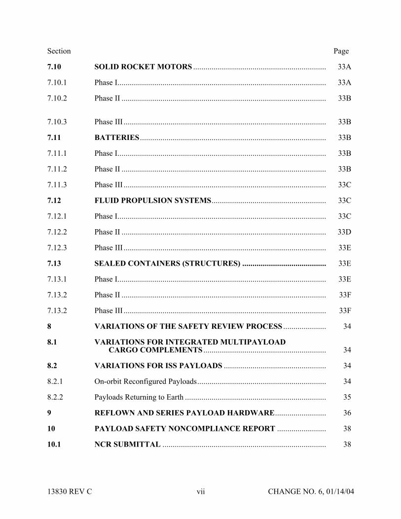
Section Page
710 SOLID ROCKET MOTORS 33A
7101 Phase I 33A
7102 Phase II 33B
7103 Phase III 33B
711 BATTERIES 33B
7111 Phase I 33B
7112 Phase II 33B
7113 Phase III 33C
712 FLUID PROPULSION SYSTEMS 33C
7121 Phase I 33C
7122 Phase II 33D
7123 Phase III 33E
713 SEALED CONTAINERS (STRUCTURES) 33E
7131 Phase I 33E
7132 Phase II 33F
7132 Phase III 33F
8 VARIATIONS OF THE SAFETY REVIEW PROCESS 34
81 VARIATIONS FOR INTEGRATED MULTIPAYLOAD CARGO COMPLEMENTS 34
82 VARIATIONS FOR ISS PAYLOADS 34
821 On-orbit Reconfigured Payloads 34
822 Payloads Returning to Earth 35
9 REFLOWN AND SERIES PAYLOAD HARDWARE 36
10 PAYLOAD SAFETY NONCOMPLIANCE REPORT 38
101 NCR SUBMITTAL 38
13830 REV C vii CHANGE NO 6 011404
Section Page
102 TYPES OF SAFETY NCRs 38
1021 Waivers 38
1022 Deviations 38
11 LIST OF FORMS 39
111 JSC FORMS 39
112 KSC FORMS 39
12 APPLICABLE DOCUMENTS 40
APPENDIX A DOCUMENT MATRIX A-1
APPENDIX B ACRONYM LIST B-1
13830 REV C viii CHANGE NO 6 011404
SECTION 1 INTRODUCTION
Implementation of the payload safety process is the joint responsibility of the Payload Organization (PO) the flight operator Lyndon B Johnson Space Center (JSC) and the launchlanding site operator John F Kennedy Space Center (KSC)
The International Space Station (ISS) and Space Shuttle Program (SSP) safety policies and requirements for ISS and Shuttle payloads are specified in the current version of NSTS 17007ldquoSafety Policy and Requirements for Payloads Using the Space Transportation Systemrdquo and the current version of the NSTS 17007 ISS Addendum ldquoSafety Policy and Requirements for Payloads Using the International Space Stationrdquo In addition unique ground safety policies and requirements are specified in the current version of 45 SPW HB S-100KHB 17007 ldquoSpace Shuttle Payload Ground Safety Handbookrdquo These documents require the PO to conduct asystematic safety analysis and to document and submit a Safety Data Package (SDP) in support of safety reviews to be conducted by the flight operator (JSC) and the launchlanding site operator (KSC)
National Aeronautics and Space Administration (NASA) Headquarters has assigned the responsibility to review submitted payload safety documentation to the Space Shuttle and Space Station Program Directors at JSC and the Director of Safety and Mission Assurance at KSC The JSC Payload Safety Review Panel (PSRP) will assess the payload design and flight operations the KSC Ground Safety Review Panel (GSRP) will assess the Ground Support Equipment (GSE) design and ground operations These two panels were formed to accomplishthe following
bull Assure that PO interpretation of the safety requirements is consistent with NASA payload safety policy
bull Conduct safety reviews as appropriate during the development of the payload associated GSE and related operations
bull Evaluate hazard analyses and Noncompliance Reports (NCRs) bull Negotiate the resolution of safety issues involving design and operation to ensure compliance
with all applicable safety requirements bull Assess payload design features that have been implemented for controlling identified hazards
and the verification approach that confirms intended system performance
13830 REV C 1 CHANGE NO 6 011404
SECTION 2 PURPOSE
The purpose of this document is to define the payload safety review process in order to assist the ShuttleISS POs in documenting compliance with the payload requirements documents specified in section 1 Specifically this document accomplishes the following
bull Defines the safety reviews necessary to comply with the system safety requirements that are applicable to payload design flight operations GSE design and ground operations for both ISS and Space Shuttle
bull Identifies the required content of the SDP bull Describes preparation for and conduct of the safety review bull Establishes the timeline for data submittal and establishes the depth of detail required for the
various submittals bull Explains safety review process variations bull Defines the payload seriesreflight review process
13830 REV C 2 CHANGE NO 6 011404
SECTION 3 SCOPE
Data submittal requirements included herein apply to hardware being submitted to both the PSRP and the GSRP unless specified otherwise This document outlines the minimum data submittal requirements the PSRP and the GSRP reserve the right to request additional data as deemed necessary to support safety documentation
The objective of the safety review process is to review the payload GSE and operations for adequate safety implementation The mission success and any scientific objectives of the payload are the responsibility of the PO and are beyond the scope of this document and process
This document does not establish design requirements
31 APPLICABLE HARDWARE
This document applies but is not limited to the following payload hardware that fliesoperates on the Space Shuttle andor ISS during any mission phase (prelaunch launch ascent on-orbit entry landing or postlanding)
bull New Payload Hardware bull Existing (reflown and series) Payload Hardware bull Hardware Associated with Developmental Test Objectives (DTOs) Detailed Supplemental
Objectives (DSOs) Risk Mitigation Experiments (RMEs) Space Medicine Program (SMP) and Human Exploration and Development of Space Technology Demonstrations (HTDs) Experiment Hardware
The document also applies but is not limited to the following payload-related hardware
bull Government-Furnished Equipment (GFE) bull Airborne Support Equipment (ASE) bull GSE
32 EXPORT CONTROL
The PSRP complies with the United States export control laws and regulations as established by the US Department of Commerce in the Export Administration Regulations (EAR) and the US Department of State in the International Traffic in Arms Regulations (ITAR) The PSRP also complies with the Space Shuttle Programrsquos export control policy in NSTS 07700 Volume V and the ISSPrsquos export control policy in SSP 50223
13830 REV C 3 CHANGE NO 6 011404
Export control factors significantly into two areas of the payload safety review process
bull Distribution of Payload Data
bull Conduct of Safety Reviews
The PSRP Executive Secretary serves as the primary exporter of payload data to the ISS International Partners (IPs) and other foreign persons in support of the payload safety review process Payload data includes safety data packages hazard reports safety review presentation materials and other payload related information Specific export control data submittalrequirements for payload organizations are listed in section 4315 of this document
The PSRP Executive Secretary takes special precautions when conducting safety reviews for payloads under export control restrictions These precautions may include restricting attendance limiting presentation materials posting signs or conducting the review in a secure facility
13830 REV C 3A CHANGE NO 6 011404
SECTION 4 RESPONSIBILITIES OF THE PAYLOAD ORGANIZATION
The PO is responsible for assuring the safety of its payload and for complying with the safety requirements contained in the technical requirements documents cited in section 1 To this end the PO must accomplish the following
bull Perform a Safety Analysis bull Identify Hazards bull Document Compliance with the Safety Requirements bull Present the Documentation to the PSRPGSRP
41 SAFETY ANALYSIS
To meet the requirements of the current version of NSTS 17007 and NSTS 17007 ISS Addendum paragraph 301 the PO shall perform a safety analysis of the payload and GSE The analysis shall consider hardware design verification testing and flightground operations The safety analysis shall begin during the payload concept phase and shall be refined and expanded as the design matures For situations in which payload hardware will be installed orreconfigured on-orbit or in which the payload will be on-orbit for an extended time safety analyses shall consider the necessity of on-orbit verificationreverification of hazard controls
411 Level of Analysis
In order to identify the hazards applicable to a payload the PO shall conduct safety analyses both at the system and subsystem levels Each system and subsystem shall be evaluated to determinethe applicability of each technical safety requirement
Selection of subsystem groupings varies and any convenient grouping may be used The following is a suggested list of subsystems biomedical caution and warning cryogenic electrical environmental control human factors hydraulics materials mechanical opticalpressure systems propulsion pyrotechnics radiation and structures
For hardware developed for or provided to the PO the PO shall
bull Obtain the appropriate safety data from the supplier or conduct an independent safety analysis
bull Conduct a safety analysis of the interfaces between the subject hardware and other elements
412 Analysis Techniques
Depending on the complexity of the payload the PO should use established analytical techniques (eg preliminary hazard sneak circuit fault tree operational hazard and failure modes and effects analyses) to obtain the data necessary to complete present and support payload hazard reports
13830 REV C 4 CHANGE NO 6 011404
413 Safety Verifications for Payloads with Catastrophic Hazard Potential (Flight Only)
The current version of NSTSISS 18798 specifies data requirements to document the verification program for payload systemssubsystems that have catastrophic hazard potential An excerpt from this document is included below for convenience
Table 4-1 - NSTSISS 18798
All payload systems having catastrophic hazard potential for the orbiter or crew as a result of operations in or near the orbiter must use hardware and procedures that have been subjected to a rigorous verification program Verification programs normally require testing to verify adequate performance margins under all environmentalconditions (qualification testing) as well as demonstrating intended system performance on flight hardware Comprehensive system-level testing on payload flight hardware supported by qualification test on protoflight or flight type hardware are the preferred verification methods It is essential that payload system performance be verified from the input stimuli to the end function
Safety-critical system performance that cannot be verified by test shall be verified by independent parties using dissimilar analysis techniques whenever possible Single party analytical efforts can be used to verify performance only when the methodology is widely accepted and conservative margins are applied to the results
The payload organization must focus its attention to all parts of the payload verification program and orbiter interface verification activities to assure that the sub-elements of the total verification program are integrated into a comprehensive system verification effort that confirms the intended system performance When the use of ground test equipment(apparatus) is required to replace flight hardware functions verification methods shall be developed by engineering personnel independent from those designing the flight systemTest requirements procedures and test apparatus shall be derived from intended functional requirements rather than from the design and all items must be maintained under strict configuration control The payload organization is responsible for developing and presenting sufficient data to the PSRP [GSRP] to substantiate that the test requirements procedures and test apparatus will provide an adequate simulation in substitution for the end function
42 HAZARD IDENTIFICATION
The primary objectives of the safety review process are to identify the potential hazards applicable to a payload including its flight GSE and ground operations and to assure that the hazard controls and verifications (including on-orbit verificationreverification of hazard controls where applicable) are adequate and in compliance with the safety requirements To assist the PO in accomplishing these objectives appropriate safety terminology has been defined in the current version of NSTS 17007
Although not exhaustive the following is a list of some previously identified flight hazard groups that have been used on hazard reports collision contamination corrosion electrical shock explosion fire injury and illness loss of orbiter entry capability and inability to egress
13830 REV C 5 CHANGE NO 6 011404
The following are basic hazard groups applicable to ground operations structural failure of support structures and handling equipment collision during handling inadvertent release ofcorrosive toxic flammable or cryogenic fluids loss of habitablebreathable atmosphere inadvertent activation of ordnance devices ignition of flammable atmospherematerial electrical shockburns personnel exposure to excessive levels of ionizing or nonionizing radiation use of hazardousincompatible GSE materials inadvertent deployment of appendages working under suspended loads and rupture of composite epoxy overwrapped pressure vessels
43 DOCUMENTATION OF COMPLIANCE WITH THE SAFETY REQUIREMENTS
The safety analysis results shall be documented in the SDP which includes applicable payload hazard report forms (JSC Form 542B and JSC Form 1230) and presented to both the JSC PSRPand the KSC GSRP as described in this document Guidelines for completing the flight hazardreport forms and preparing the SDPs are found in JSC 26943 ldquoGuidelines for the Preparation of Payload Flight Safety Data Packages and Hazard Reports for Payloads Using the Space Shuttlerdquo current issue
For SDP preparation the PO is responsible for using the current version of all applicable forms and safety documentation The PO may verify current formsdocuments by contacting theExecutive Secretary to the PSRP or the Chairman of the GSRP These forms are listed in section 11
431 Data Submittals
Although there will be some duplication of material contained in data submittals prepared for PSRP and GSRP reviews each package serves a different purpose and must stand alone
Data submittals which may include SDPs and other supporting information (eg action item responses) should identify the flight on which the payload is manifested (if known) and be formally submitted in English to the Executive Secretary PSRP or the Executive Secretariat GSRP Data should be formally transmitted under the signature of the Program Manager
Safety review meetings are scheduled to be held approximately 45 calendar days after receipt of an acceptable SDP (ie an SDP that satisfies all the requirements in this document)
The SDP will be made available to the PSRPGSRP members and various other NASAcontractor technical and administrative personnel who support the Panels For ISS payloads this may include International Partner representatives to the PSRP
Payload safety data must be submitted electronically via the Internet using the Payload Safety Data Management System (DMS) located at the following URL
httppsrpjscnasagov
The DMS System Administrator (tel 281-483-9078) can provide information on acceptable software applications electronic addresses detailed login instructions and system procedures POs may also access the DMS via a hyperlink at the top of the Payload Safety homepage located at the following URL
13830 REV C 6 CHANGE NO 6 011404
httpwwwsrqajscnasagovpce
POs must obtain approval from the PSRP Executive Secretary or Executive Secretariat GSRP to submit flight or ground safety data respectively by alternate means or to submit supplementary data in hard copy format Hard copy submittals must be single-sided and sequentially paginated from the cover sheet to the last page of the package
Once the SDP has been electronically submitted the PO must send the transmittal lettersdocument signature pages and signed original Hazard Reports (HRs) to the appropriate Panel contact
Executive Secretary PSRPNASA Lyndon B Johnson Space Center
Mail Code NC4 2101 NASA Road 1
Houston TX 77058-3696
Executive Secretariat GSRP NASA John B Kennedy Space Center
Mail Code UB-F3 Kennedy Space Center FL 32899-0001
13830 REV C 6A CHANGE NO 6 011404
4311 Submittal of Proprietary Data
If proprietary data are submitted in the SDP the transmittal letter must include the following statement
This payload safety data package contains proprietary data on the following pages [listthe appropriate page numbers] [Insert name of the payload organization] acknowledges awareness and acceptance of the GSRP and the PSRPrsquos policies and methods of processing proprietary data [Insert name of the payload organization] also will provideany additional protective measures it deems necessary over and above that provided by the panels during meetings
The transmittal letter and the first page of the SDP must identify the specific pages that contain proprietary information Insert the word ldquoPROPRIETARYrdquo at the top and bottom of each pagethat contains proprietary data The word ldquoPROPRIETARYrdquo shall be in all capital letters in alarge font size and style that is easily discernible from the rest of the text
In addition to the proper submittal of proprietary information the PO should be aware of the following while attending PSRPGSRP safety reviews Technical Interchange Meetings (TIMs) and action item closure meetings
bull PSRPGSRP meetings are not conducted in secure facilities Thus when it is necessary torecess meetings (eg lunch and breaks) the POs will be responsible for protecting any proprietary data distributed during the meeting (other than that logged and distributed byNASA as part of the SDP)
bull If any proprietary data are to be presented or discussed during the meeting prior to the meeting the PO will notify the PSRP Executive SecretaryGSRP Chairman who will then make arrangements to monitor attendance close the doors and post a sign noting that accessto the meeting is controlled
bull The PO will be responsible for retrieval and disposition of any proprietary material distributed at the meeting (other than that logged and distributed by NASA as part of the SDP) with the exception that two copies of proprietary material distributed by the PO at the meeting will be retained by the PSRPGSRP in a protected file
When the PSRPGSRP receives proprietary data included in the SDPs such data will be handledin a manner that will protect the interests of the PO These procedures include trackingdistributed materials protecting files and restricting reproduction In order to exercise reasonable care in protecting proprietary data in connection with the payload safety review process NASA will ensure that proprietary data are distributed only to persons who have a needto review such data in support of panel functions Furthermore distributed data that is returned to the PSRP Executive SecretaryGSRP Chairman after use will be destroyed via the NASAsecure disposal process
13830 REV C 7 CHANGE NO 6 011404
The protection of material marked ldquoPROPRIETARYrdquo creates an added burden on thePSRPGSRP review support system so the PO should mark only those items that are proprietary The PO should coordinate with the PSRP Executive SecretaryGSRP Chairman to explore such alternatives as providing the proprietary material in a separate package when it is a very small portion of the overall SDP If a separate proprietary briefing package (not containedin the SDP) is to be presented to the PSRPGSRP during the review the PO shall provide at least20 copies of such material for distribution at the review
If the PO discovers that some portion of the SDP marked ldquoPROPRIETARYrdquo is no longerconsidered such the PO must inform the PSRP Executive Secretary andor the GSRP Chairmanin writing
4312 Submittal of Copyrighted Data
Payload organizations are hereby informed that payload documentation submitted to NASA must be reproduced and distributed to the members of the PSRPGSRP and to associated technicalsupport personnel Accordingly copyrighted data shall not be included in the submitteddocumentation unless the PO 1) identifies such copyrighted data and 2) grants to theGovernment or acquires on behalf of the Government a license to reproduce and distribute the data to these necessary recipients
4313 Submittal of Translated Data
For all documents submitted by the PO to the PSRPGSRP that have been translated intoEnglish the English translation shall be the official document
4314 Submittal of Toxicological Data for SSP and ISS Payloads (Flight Only)
The ShuttleISS payload safety review process requires biomedical safety assessments of potentially hazardous materials such as chemicals microorganisms and radioisotopes In order for these assessments to be available for the safety reviews the JSC Toxicology Group requires POs to submit test sample data substantially in advance of the safety reviews See JSC 27472 ldquoRequirements for Submission of Test Sample-Materials Data for Shuttle Payload Safety Evaluationsrdquo current issue for the timeline and data requirements for these early submittals The PO must attach both the data submitted to JSC Toxicology Group and the JSC response (when available) to the applicable hazard report that is a part of the SDP Should toxicology submittals involve proprietary data see section 4311
4315 Submittal of Export Control Data (Flight Only)
The export control data submittal requirements in sections 43151 and 43152 apply to USpayload organizations only IP payload organizations are not required to provide the US export control classification of their safety data packages In the event that an IP SDP requires a USexport control classification NASA export control resources will be used to classify the SDP
13830 REV C 8 CHANGE NO 6 011404
43151 ISS Payloads
Distribution of ISS payload safety data packages to the ISS IPs is a standard part of the payload safety review process
The PO must identify the export control classification of the SDP payload data in its transmittal letter The first page of the SDP must also identify the export control classification of the data
The PSRP Executive Secretary will not distribute an SDP with an unknown export controlclassification to the IPs Safety reviews may be delayed or cancelled for ISS payloads with unresolved export control issues
The POrsquos safety review presentation materials must have the same export control classification as the SDP submitted for review or a less restrictive export control classification
43152 Shuttle Payloads
Distribution of Shuttle payload safety data packages to the ISS IPs is not a standard part of the payload safety review process
Shuttle payload safety data packages are not distributed to the IPs unless the PSRP identifies a specific need to do so If a need is identified the PSRP Executive Secretary will work with the PO and the SSPrsquos export control resources to obtain the export control classification of the SDP
The PO may include the export control classification of the SDP payload data in its transmittalletter and on the first page of the SDP if the classification is known prior to SDP submittal
432 Hazard Reports
The purpose of the hazard reports is to document the POrsquos safety assessment in a manner that reflects how the payload design demonstrates compliance with the safety requirements The hazard reports are used as a method to systematically assess compliance with the safety requirements
The flight SDP submittal must contain all flight hazard reports the ground SDP submittal mustcontain all ground hazard reports Each hazard report must be signed and dated by the payloadprogram manager prior to submittal Hazard reports shall be prepared on JSC Form 542B JSCForm 542B-1 or JSC Form 1230 (see section 11) or an equivalent form that contains all information required on the JSC forms Section 7 organized by area of design identifies minimum support data for flight hazard reports JSC 26943 contains guidelines for preparingpayload flight hazard reports
13830 REV C 8A CHANGE NO 6 011404
Following any technical discussion the PSRPGSRP Chairman will provide a disposition for each hazard report This disposition may take one of the following forms 1) approved aswritten 2) approved with modification 3) approved with an action to be performed by the PO andor PSRPGSRP and 4) not approved
The PO is responsible for retaining and maintaining the original hazard reports after approval
44 SAFETY REVIEW PRESENTATION
The PO should be prepared to present information submitted in the SDP to the appropriate safety panel during scheduled reviews (see sections 611 and 612) During reviews the PO shouldprovide briefing chart handouts sufficient for the number of people expected to attend the review
13830 REV C 9 CHANGE NO 6 011404
SECTION 5 SAFETY REVIEW OVERVIEW
51 LOCATION
Safety reviews for payload design and flight operations are usually conducted at JSC The safetyreviews for GSE design and ground operations will normally be conducted at KSC The PO shall coordinate the timing of the PSRP reviews with the PSRP Executive Secretary The PO shall coordinate the timing and location of the GSRP reviews with the GSRP Chairman
52 INITIAL CONTACT MEETING
The PO may receive initial contact safety briefings by the JSC and KSC safety representatives The JSC briefing normally held during the first integration meeting at JSC should be scheduledby contacting the Payload Integration Manager (PIM) at JSC For ISS payloads contact the ISSPIM The KSC briefing is usually held in conjunction with the first Ground Operations Working Group (GOWG) meeting which is scheduled through the Launch Site Support Manager Integration Manager (LSIM) at KSC
The briefing includes an overview of the technical and system safety requirements to be met by the PO plus instructions for conducting the safety reviews The PO should provide a schedule ofpayload milestones and request a phase 0 or phase I safety review when the payload design concept has been developed
53 TYPES OF MEETINGS
Safety reviews may take place in person via teleconference or by correspondence Review meetings may be formal or out-of-board as deemed appropriate by the Panel Chairman
bull Formal Meeting Formal meetings constitute a gathering of the safety review panel representatives of the PO and the appropriate supporting technical staff
bull Out-of-Board Meeting Out-of-board meetings do not require the full safety panel Attendees may include the Panel Chairman Safety representative(s) representatives of the PO and others necessary to address the issues that may be involved
bull Safety TIM The review panel andor associated technical staff may convene upon request in order to assist in interpreting safety requirements or to coordinate safety analysesissues prior to safety reviews Requests for flight safety TIMs should be coordinated with the PSRP Executive Secretary Requests for Ground Safety TIMs should be coordinated with the GSRP Chairman Material to be addressed during the TIM should be provided 14 calendardays prior to the TIM
bull Splinter Meetings Splinter meetings may be held concurrently with a safety review to discuss detailed technical concerns
13830 REV C 10 CHANGE NO 6 011404
54 PAYLOAD CATEGORIES
Traditional payload safety compliance assessment is accomplished using a phased safety review process (phases 0 I II III) that corresponds to the hardware conceptual preliminary and critical design review phases and verificationvalidation of the payload (see section 6) Successful completion of each safety phase is documented by SDPHR submittals to and approval by the PSRPGSRP
To streamline this process the PSRP has implemented procedures and data requirements to minimize formal PSRP review time for payloads with routine hazardsstandard controlsverifications This allows the PSRP to concentrate review time on payload systems withthe highest hazard potential ldquomust-workrdquo functions andor nonstandard controls and verification methods POs may document routine hazards and standard controls and verifications on the JSC Form 1230 ldquoFlight Payload Standardized Hazard Control Reportrdquo
Based on the phase I SDP new payloads are categorized by the PSRP into one of three categories of complexity (basic intermediate or complex) with respect to hazard potential as shown in Table 5-1 below The review process is then tailored to the complexity of the payload design and adequacy of documentation In addition the process permits all payloads to document standard hazards that have standard controls and verifications on JSC Form 1230 which may be approved by the PSRP without a formal PSRP meeting Details concerning basicand intermediate categories are contained in sections 541 and 542 respectively Complexpayloads use the review process detailed in section 6 Reflown and series payloads use thereview process outlined in section 9
Table 5-1 - PAYLOAD CATEGORIES
PayloadCategory
Defined Hazards
Basic The only hazards identified are ldquostandardrdquo as specified on the JSC Form 1230 The appropriate hazard controls are found on JSC Form1230
Intermediate 1) The payload has ldquouniquerdquo hazards (ie hazards not found on the JSC Form 1230) but has controls and verification methods that have been historically accepted by the PSRPOR
2) The payload has ldquostandardrdquo hazards (ie hazards identified on the JSC Form 1230) but uses controls and verification methods other than those identified on the JSC Form 1230
Complex The payload has unique hazards with hazard controls that are
a Active ldquomust workrdquo functions such as electromechanical or pyrotechnic separation systems or actuatorsmechanisms providing structural load paths
OR b Nonstandard or have nonstandard verification methods that
depart from historically accepted techniquesOR c Operationally complex requiring flight or ground personnel
intervention to assist in controlling the hazard
13830 REV C 11 CHANGE NO 6 011404
If after a payload category has been assigned the PO a) identifies previously undefined hazards or b) implements design changes that may create new hazards the PO must submit a revisedSDP which may result in a reclassification of the payload category
541 Review Process for Basic Payloads (Flight Only)
Basic payloads (see Table 5-1 above) have a very low level of complexity which may allow the payload to complete the safety process out of board However the PO will submit an SDP that will document the applicable hazards controls and verifications Submittal will follow the standard procedure detailed in section 431 and approval may be obtained without a meeting The following data are required for the simplified SDP for hardware design and flight operations
bull Brief description of the hardware design and flight operations with schematics and block diagrams as appropriate
bull Summary of the safety analysis results that documents compliance with the design verification and applicable on-orbit verificationreverification requirements for the identified standard hazards
bull Documentation of all applicable hazards controls and verifications on hazard report(s) (eg JSC Form 1230Form 542)
bull Certificate of Payload Safety Compliance (JSC Form 1114A) signed by the ProgramManager
542 Review Process for Intermediate Payloads (Flight Only)
In addition to the standard hazards found in Basic payloads the Intermediate payload has unique hazards that have standard controls and verification methods (including applicable on-orbit verificationsreverifications) that have been historically accepted by the PSRP Intermediate category payloads should require one or two reviews of the unique hazards but the basic hazards may be addressed on a Form 1230 and approved out of board The PSRP will determine the need for a second review for unique hazards at the completion of the first review The determination will be based primarily upon the completeness and quality of the unique hazard reports Requirements for SDP submittal are the same as those stated in section 431
55 SCHEDULE OF REVIEWSPHASES
The schedule for formal phase 0 I and II payload safety reviews generally relates to the payload development schedule Phase 0 is held during the concept phase or at the start of payload design Phase I is near the Preliminary Design Review (PDR) phase II is near the Critical Design Review (CDR) The PO should set the review schedule to obtain maximum benefit to payloaddevelopment based on the results of the safety reviews
ISS payloads may include multiple major systems or components each working to a uniqueschedule These may be individually baselined and categorized (see section 54) which allows them to progress through the payload safety process in accordance with their own schedule (see section 82)
13830 REV C 12 CHANGE NO 6 011404
Phase III is associated with completion of payload safety verifications andor the start of ground processing When establishing a timeline for phase III the PO should allow enough time to closepotential issues that may result from a phase III review The timing and completion of the phase III review and safety certification are critical to the launch schedule The flight and ground phaseIII completion requirements restated below are in the current version of NSTS 17007 and NSTS 17007 ISS Addendum and apply to all payloads
The JSC and KSC Phase III safety review and ground safety certification must be completed 30 days prior to delivery of the payload ASE and GSE to the launch sitehellip
If any verification items remain open on the flight hazard reports the PO must provide rationale to support the safety of starting ground processing with these items open The rationale is to be submitted to both the PSRP and GSRP The PSRP will review the rationale and provideconcurrence to the GSRP
To schedule KSC Ground safety reviews contact the GSRP Chairman to schedule JSC Flight safety reviews contact the PSRP Executive Secretary (see section 431)
56 SAFETY REVIEW COMPLETION
561 Documentation of Phase Completion
During a formal meeting the Panel Chairman will make an official announcement that the safety phase is complete or incomplete (open) This announcement will be recorded and distributed bythe PSRPGSRP in the official meeting minutes Incomplete phases are usually attributable to overdueopen action items or unsigned (open) hazard reports The PSRPGSRP will issue officialcorrespondence to document closure of open action itemssignature of open hazard reports thatoccurs after the phase review The correspondence that closes the last open action itemhazardreport for that phase will include a statement that the safety phase is considered complete
For out-of-board reviews safety review process completion will be documented by formal correspondence
562 Completion Criteria for Phase I II and III
Successful completion of phase I and II reviews is accomplished by obtaining approval (Panel Chairmanrsquos signature) of hazard reports at the appropriate phase level and closure of applicable phase III action items
After submission of all required data the criteria for successful completion of the safety review process at the phase III level for both flight and ground reviews are as follows
bull All payload hazard reports are signed by the payload Program Manager and the Panel Chairman at the phase III level
bull All NCRs are approved bull Safety review action items are formally closed in the safety review meeting minutes or
documented closed in separate correspondence bull A signed Certificate of Ground Payload Safety Compliance provided to the GSRP (for phase
III ground safety)
13830 REV C 13 CHANGE NO 6 011404
Approval of the phase III safety data by the PSRP and GSRP is with the understanding that the data represent the actual design and operations of the payload Should safety issues arise after the safety process is complete the safety panels reserve the right to request additional data deemed necessary to reassess the payload
563 Completion Criteria for SeriesReflight
The criteria for successful completion of a series or reflight safety review is that all data required by section 9 Reflown and Series Payload Hardware have been submitted and approved
57 POST PHASE III SAFETY ACTIVITY
571 Certificate of Flight Payload Safety Compliance
The PO must present a signed Certificate of flight Payload Safety Compliance to the PSRP Executive Secretary no later than 10 days prior to the Flight Readiness Review (FRR)
572 Configuration Control
When changes to the design configuration or operations of the payload are required subsequent to phase III the PO shall assess those changes for possible safety implications including the effect on all interfaces The assessment shall be forwarded to the PSRPGSRP for review andapproval If the change has ground safety implications it must be reviewed with the KSC panel prior to proceeding with ground processing New or revised hazard reports and support datashall be prepared where applicable and submitted for approval as indicated in section 431 The need for delta phase III safety reviews will be determined by the PSRPGSRP Chairman Satisfactory completion of these activities is mandatory prior to the start of affected ground activities or launch
Any test failures anomalies or accidents involving payload flight hardware or software that occurs between the completion of phase III and launch must be promptly reported to the PSRPGSRP Safety impacts if any should be identified
573 Verification Tracking Log
Open verification items must be tracked on a flight or ground safety Verification Tracking Log (VTL) (see section 11)
bull Flight Safety From Phase III until L-60 days the PO shall update and provide the VTL to the PSRP Executive Secretary once a month From L-60 days until launch the PO shall provide a weekly update to the VTL All VTL open items must be closed no later than 4PM Central time on the last business day prior to launch Items that cannot be closed at this time will require the transmission of a facsimile closing the open VTL items to the Mission Evaluation Room (MER) at NASA JSC no later than L-6 hours Contact the PSRP Executive Secretary for MER delivery instructions
bull Ground Safety The initial submittal of the ground safety VTL is required with the phase III ground SDP Following the completion of the phase III review the ground safety VTL shall be updated monthly prior to hardware arrival at KSC If there are open flight verifications
13830 REV C 14 CHANGE NO 6 011404
that are constraints to ground processing the PO must also include those items of the flight VTL After the delivery of the payload ASE or GSE to the launch site the safety VTL(s) shall be updated at least weekly More frequent updates to the safety VTL(s) may be required if the open items must be closed to allow work to continue
574 Documentation of Safety Process Completion
Final flight safety approval is documented by the PSRP Chairmanrsquos signature on the Certificateof Flight Readiness (CoFR) for the planned flight
Final ground safety approval is documented by a letter from the KSC Director Safety Assurance to the KSC Director Customer Service Space Station and Shuttle Payloads Processing statingthat the Ground Safety Review Process has been completed and the payload may begin ground processing
13830 REV C 15 CHANGE NO 6 011404
SECTION 6 SAFETY PROCESS
61 GENERAL
611 Preparation
In preparation for a phase safety review the PO will submit an SDP as indicated in section 431 If phase reviews are combined (eg a phase III review) the SDP shall include the datarequirements that apply to all the appropriate phases The depth and number of the plannedreviews are dependent on the complexity technical maturity and hazard potential of the payload and may be modified by the Panel Chairman in conjunction with the PO
The PO should provide sufficient technical support personnel to answer questions posed by the PSRPGSRP in support of the agenda items
Listed below are general agenda topics for safety review meetings These insure that the safety review meetings proceed smoothly and contain the necessary information to facilitate the review
612 General Meeting Agenda Guidelines
The PO should coordinate all meeting agenda with the PSRP Executive Secretary or the GSRP Chairman prior to the safety review meeting and provide the final agenda in advance The fundamental elements of all Safety Review Meeting Agenda are as follows
a Introduction of the Meeting and Participants by the JSC Safety Reliability and Quality Assurance (SRampQA) Payload Safety Engineer (PSE)
b Opening Remarks by Chairman and the Payload Program Manager
c Discussion of Pre-Review Activity Led by the PSE
d Program-level Overview (including areas of responsibility)
e Program Milestone Schedule Provide the Program Milestone Schedule includingbut not limited to
(1) design stages and reviews
(2) hardwaresoftware build status
(3) testing and verification activities
(4) delivery integration and launch activities and
(5) safety review dates
f Mission Objectives including overview of mission objectives and general criteria for a successful mission
13830 REV C 16 CHANGE NO 6 011404
g SystemSubsystem Technical Presentation Overview including enough information to allow the PSRPGSRP to gain a general technical understanding of the systemsinvolved in the payload operations Highlight any design changes since the previous safety reviews
h Operations Overview describing planned operations and known contingencies Plan to discuss detailed operations that relate to payload safety in conjunction with the appropriate hazard report presentation Highlight any operations changes made tothe operations that impact the safety of the payload since the previous review
i Safety Assessment Summary including safety assessments performed to identify hazards any failures or anomalies that occurred after development testing and the corrective actions Present responses to agreements and formal action items including a summary of open action items and associated plans for closure Provide sufficient information to demonstrate that a comprehensive hazard analysis has been performed Provide an overview of hazards and how they relate to the hazard reports and discuss safety-related items that are not reflected in the hazard reports
j Phase-specific Topics Additional phase-specific topics for the agenda should be drawn from the data that are required to be included in the SDP for that phase (see sections 621 631 641 and 651) If not included as one of the general agendatopics these data should be addressed as separate agenda items
k Hazard Report Presentation Unless otherwise agreed to by the PSRPGSRPpresent all hazard reports in full associated noncompliancereportswaiversdeviations previously assigned action itemsagreements that involved modification of hazard reports and associated action itemagreement responses
l Action Item Review Both the PO and the PSRPGSRP will review and agree toactions and due dates assigned during the course of the safety review to ensure that there are no misunderstandings These action items will be printed and signed during the review
m Closing Comments Payload Program Manager and Panel
62 PHASE 0 SAFETY REVIEW
The optional phase 0 safety review is provided as a service to the PO The objectives of the meeting are to
bull Assist the PO in identifying hazards hazard causes and applicable safety requirements early in the development of the payload
bull Adequately describe the hazard potentialbull Answer questions regarding the interpretation of the safety requirements or the
implementation procedures of this documentbull Provide guidance to the PO for preparing the safety data required for subsequent safety
reviews
13830 REV C 17 CHANGE NO 6 011404
621 Phase 0 Data Requirements
The following data are required for the phase 0 SDP and must be submitted as stated in paragraph 431
a For payload design and flight operations
(1) Conceptual payload description (including subsystems) and missionscenario
(2) Description of safety-critical subsystems and their operations
(3) Flight hazard reports (JSC Form 542BForm 1230)
b For GSE design and ground operations
(1) Conceptual payload description and brief mission scenario
(2) Conceptual GSE description and operations and description of payload design that is safety critical during ground operations
(3) Ground operations scenario
(4) Ground hazard reports (JSC Form 542B)
The description of the payload and its operation must be of sufficient detail to permit identification of all subsystems that may create hazards Emphasis should be given to thosesubsystems that store transfer or release energy The descriptions of the safety-critical subsystems must be of sufficient detail to identify the hazards in terms consistent with the conceptual design In addition the PO shall address tentative plans for any flight operation (eg extravehicular activity reverification of hazard controls) or ground operation that would require personnel certification to perform hazardous procedures
622 Phase 0 Hazard Reports
The purpose of a phase 0 hazard report is to document and scope the specific hazards identified It is intended to be a working document for discussion and critique at the phase 0 safety review and will not require signatures A hazard report must be prepared for each unique hazardidentified in the safety analysis The hazards contained on the phase 0 hazard report must reflect the payload conceptual design and operations existing at the time of the phase 0 review For phase 0 the PO may identify hazard controls verification methods or status of verifications
63 PHASE I SAFETY REVIEW
The purpose of the phase I safety review is to obtain PSRPGSRP approval of the updated safety analysis that reflects the preliminary design and operations scenario of the payload At this pointthe PO shall present a refined safety analysis that identifies all hazards and hazard causes inherent in the preliminary design evaluates all hazards for means of eliminating reducing or controlling the risk and establishes preliminary safety verification and on-orbit verificationreverification methods The PO shall provide a preliminary identification of the payload interfaces and of the hazards presented by these interfaces
13830 REV C 18 CHANGE NO 6 011404
631 Phase I Data Requirements
The following data are required for the phase I SDP and must be submitted as stated in paragraph 431
a For payload design and flight operations
(1) Updated payload description (including subsystems) and mission scenario
(2) Updated descriptions of safety-critical subsystems and their operations including schematics and block diagrams with safety features inhibits and controls identified Identify any safety-critical subsystems that are computer controlled and identify the functional architecture associated with that computer control
(3) Updated and additional flight hazard reports (eg JSC Form 542BJSC Form 1230) including appropriate support data (see section 7) For payloads thathave catastrophic hazard potential document the verification programoutlined in NSTSISS 18798
(4) A summary list (in the payload description) of orbiter- andor ISS program-provided critical services and an explanation (in the appropriate hazard reports) of the orbiter andor ISS services used to control andor monitorpayload hazards (NSTS 17007 and NSTS 17007 ISS Addendum current version)
(5) For ISS payloads a presentation of the Fire Detection and Suppression (FDS) implementation approach For sub-rack payloads the PO shall address the integrated system approach (using sub-rack services andor ISS services) to fully define the FDS implementation strategy In addition submit JSC Form 1428 to document methods and verifications used to detect and suppress a fire event for each payload volume
(6) Discussion of design features supporting verificationreverification of hazard controls on-orbit and associated constraints
(7) A tabulated list of tentative toxic materials and support data per JSC 27472(see section 4314)
(8) A list of all battery types their uses manufacturer and applications
(9) A preliminary description of all pyrotechnic devices and their functions
(10) Preliminary on-orbit maintenance safety assessment as outlined in NSTSISS 18798
b For GSE design and ground operations
(1) Updated payload description and brief mission scenario
13830 REV C 19 CHANGE NO 6 011404
(2) Updated descriptions of GSE payload subsystems that present a potential hazard during ground processing and their ground operations Schematics and block diagrams with safety features and inhibits identified should be included Design data for hazardous systems (pressure lifting etc) shall be summarized in a matrix Contact the GSRP Chairman for sample formats
(3) Updated ground operations scenario including postflight ground operationsat the primary alternate and contingency landing site The scenario should highlight unique payload requirements at the launch pad such as continuous power through a T-0 umbilical
13830 REV C 19A CHANGE NO 6 011404
(4) Updated ground hazard reports (JSC Form 542B) including appropriatesupport data
(5) Ordnance data required by the current version of KHB 17007 Appendix D
(6) Estimated KSC on-dock arrival date
632 Phase I Hazard Reports
The PO shall prepare phase I hazard reports for each hazard identified as a result of the safety analysis for the preliminary design and operations scenario of the payload Hazard reports shallbe added to or deleted from those agreed to during phase 0 to reflect the updated safety analysis Rationale for deleting a hazard agreed upon at phase 0 shall be presented during the phase I review
For phase I the PO shall identify hazard controls for each hazard cause identified at phase 0 A direct correlation between each hazard cause and the corresponding hazard control(s) must be clearly shown on the report Sufficient supporting information detailing each hazard control must be provided
Verifications should include the types of tests analyses inspections or procedures to be used to verify each hazard control including all orbiter- or ISS-provided services or interfaces both prelaunch and on-orbit A direct correlation between each verification method and the corresponding hazard control must be clearly shown on the report Each verification item should be independent and have a designator that allows for individual tracking of verification status
Manufacturingassembly proceduresprocesses that are critical in controlling hazards that cannot or will not be verified by subsequent inspection or test must be verified during the manufacturingassembly process An independent verifier as specified by the PO shall attest toproper completion of the procedureprocess Critical proceduresprocesses which require special monitored verification (Mandatory Inspection Points [MIPs]) shall be identified in preliminary fashion (NSTS 17007 and NSTS 17007 ISS Addendum current version)
If available the PO should provide a tentative schedule for completion of each verification taskand correlate with the integration schedule
64 PHASE II SAFETY REVIEW
The purpose of the phase II safety review is to obtain panel approval of the updated SDP that reflects the CDR-level design and operations scenario of the payload The phase II safety analysis identifies all hazards and hazard causes defines and documents implementation of a means for eliminating reducing or controlling the risks and documents finalized specific safety verification and on-orbit verificationreverification methods (test plans analysis and inspection requirements etc) Payload interfaces mission and ground operations procedures and timelines that were not addressed during the phase I safety review shall be assessed for safety hazards The payload interfaces to be assessed shall include those between the Shuttle andor ISS and the payload and among the various components that make up the payload (the spacecraft upper stages space platforms pallets experiments ASE ancillary flight equipment GSE KSC Facilities GFE etc) Newly identified hazards shall be documented in additional hazard reports For this review the PO should provide the estimated KSC on-dock arrival date
13830 REV C 20 CHANGE NO 6 011404
641 Phase II Data Requirements
The following data are required from the PO for phase II and must be submitted as stated in paragraph 431
a For payload design and flight operations
(1) Updated payload description (including subsystems) and mission scenario
(2) Updated descriptions of safety-critical subsystems and their operations including schematics and block diagrams with safety features and inhibits identified Provide electrical schematics that clearly identify the requirednumber of independent inhibits controls and monitoring provisions Present a summary of the test and analytical efforts required to verify the intended performance of all safety-critical hardware For a computer-based control system that is used to prevent criticalcatastrophic hazards provide the following datadescriptions bull Functional architecture bull Expected interactions bull Results of unexpected interactions bull Protections for common cause failures bull Development process for databases hardware software and
hardwaresoftware (3) Updated and additional flight hazard reports (eg JSC Form 542BJSC
Form 1230) including appropriate support data (see section 7) For payloads that have catastrophic hazard potential document the verification program outlined in NSTSISS 18798
(4) Updated summary list and explanation of orbiter- andor ISS-provided critical services
(5) For ISS payloads an update of the FDS implementation approach Include information on use of forced air flow wire derating circuit protection materials usage parameter monitoring (fan speeds temperatures currentetc) and responses to an out-of-limit condition and suppression approach For sub-rack payloads the PO shall address the integrated system approach (using sub-rack services andor ISS services) to fully define the FDS implementation strategy Updated JSC Form 1428 to reflect specific test (or analysis) procedures to be used along with the schedule for completion of FDS verification tests analyses or inspections
13830 REV C 21 CHANGE NO 6 011404
(6) Verification methods associated with hazard controls that require on-orbit verification andor reverification and the applicable approach (include rationale constraints and detailed methodology)
(7) An updated tabulated list of planned toxic materials and support data per JSC27472 (see section 4314) Updates should include changes in testmaterials changes in test conditions and any alternate test materials
(8) Updated list of all battery types their uses manufacturer and applications
(9) A list of all pyrotechnic devices their functions chemical composition critical components inspection plan verification plan and aging degradation evaluation plan
(10) List of hazard controls that require crew procedures andor training
(11) A record of test failures anomalies and accidents involving qualification or potential flight hardware Include a safety assessment for items which may affect safety
(12) The status of all action items assigned to the PO during phase I
(13) Detailed on-orbit maintenance safety assessment as outlined in NSTSISS 18798 Identify maintenance activities safe access areas and reverification of safety critical features
b For GSE design and ground operations
(1) Updated payload description and brief mission scenario
(2) Updated descriptions and matrices of the GSE the payload subsystems that present a potential hazard during ground processing and their ground operations Include updated schematics and block diagrams with safety features and inhibits identified Electrical schematics must show all payloadGSE grounding
(3) Updated ground operations scenario including postflight ground operations at the primary alternate and contingency landing sites
(4) Updated and additional ground hazard reports (JSC Form 542B) includingappropriate support data
(5) Updated ordnance data required by the current version of KHB 17007 Appendix D
(6) Updated KSC on-dock delivery date
(7) Specific engineering drawings and stress analyses of subsystems whenrequested by the GSRP Chairman
(8) A list of safety-related failures and mishaps that have occurred
13830 REV C 22 CHANGE NO 6 011404
(9) The status of all action items assigned to the PO during phase I
(10) A list of technical operating procedures that will be used at KSC with apreliminary designation as to which ones are considered hazardous
13830 REV C 22A CHANGE NO 6 011404
642 Phase II Hazard Reports
The PO shall prepare the phase II hazard reports by revising the phase I hazard reports to reflectthe completed payload design and flightground operating procedures If the payload designchanges from phase I to phase II so that a phase I hazard report may be deleted present a brief statement of rationale for deleting the report in the phase II SDP The GSRPPSRP willdisposition the hazard reports
Address all critical proceduresprocesses including the plan for verification Verifications shall refer to specific test (or analysis) procedures and summarize passfail criteria to be used Specifythe schedule for the completion of each specific verification test analysis or inspection
65 PHASE III SAFETY REVIEW
The purpose of the phase III safety review is to obtain PSRPGSRP approval of the SDP and safety compliance data that reflects the safety verification findings The focus of this review is to assess safety verification testing and analysis results If verifications critical for establishing the acceptability of the fundamental design of the payload for safety are not completed prior to the phase III review then subsequent reviews may be required prior to hazard report approval All verifications that are open at the time of the phase III SDP submittal must be included on the safety VTL Items listed on the VTL should be planned open work items such as groundprocessing at KSC
651 Phase III Data Requirements
The following data are required for the phase III SDP and must be submitted as stated in paragraph 431
a For payload design and flight operations
(1) Final as-built payload description (including subsystems) and mission scenario
(2) Updated descriptions that define the final configuration of the safety-critical subsystems and their operations including schematics and block diagramswith the as-built payload safety features and independent inhibits controls and monitoring provisions identified Address applicable features andconstraints relating to on-orbit verificationreverification of hazard controls
For a computer-based control system that is used to prevent criticalcatastrophic hazards provide verifications for the following bull Functional architecture bull Expected interactions bull Results of unexpected interactions bull Protections for common cause failures bull Flight article databases hardware software and hardwaresoftware
operate as designed
13830 REV C 23 CHANGE NO 6 011404
(3) Updated (and additional if required) flight hazard reports including support data that reflect the final configuration of the as-built payload and planned use For payloads that have catastrophic hazard potential document theverification program outlined in NSTSISS 18798
(4) Final summary list and explanation of orbiter- andor ISS-provided critical services
(5) For ISS payloads a finalized FDS implementation approach Include information on use of forced air flow wire derating circuit protectionmaterials usage parameter monitoring (fan speeds temperatures currentetc) and responses to an out-of-limit condition For sub-rack payloads the PO shall address the final integrated system approach (using sub-rack services andor ISS services) to fully define the FDS implementation strategy Final JSC Form 1428 to summarize the results of the completedtests analyses andor inspections and refer to particular test reports by document number title and date
(6) Updated (and additional if required) verification methods associated with hazard controls that require on-orbit verification andor reverification and the applicable approach (include rationale constraints and detailed methodology)
(7) A final tabulated list of toxic materials and support data per JSC 27472 (see section 4314) including additions and changes in test materials changes in test conditions and any alternate test materials
(8) A final list of all battery types their uses manufacturer and applications
(9) A final list of all pyrotechnic devices installed or to be installed on the payload The list will identify for each cartridge the function to be performed the part number the lot number and the serial number
(10) Updated list of hazard controls that require crew procedures and or training
(11) An updated record of test failures anomalies and accidents involving qualification or potential flight hadware or baselined flight software if the software is used for hazard control Include a safety assessment for items which may affect safety
(12) The status of all action items assigned to the PO through phase II
(13) Payload Flight Safety VTL (JSC Form 764)
13830 REV C 24 CHANGE NO 6 011404
(14) Identification of flight safety noncompliances Flight safety NCRs must be approved as either a waiver or a deviation before the phase III safety review can be completed A signed copy of each approved safety waiver andor deviation shall be included in the phase III SDP attached to the appropriate hazard report
(15) Finalupdated on-orbit maintenance safety assessment as outlined in NSTSISS 18798
b For GSE design and ground operations
(1) Final as-built payload description and brief mission scenario
(2) Updated descriptions and matrices defining the final configuration of the GSE the payload subsystems that are potentially hazardous during ground processing and their ground operations Include updated schematics andblock diagrams with the as-built safety features and inhibits identified
(3) Updated and finalized ground operations scenario including postflight ground operations at the primary alternate and contingency landing sites
(4) Updated and additional ground hazard reports including support data thatreflect the final configuration of the as-built GSE and planned payloadGSE use
13830 REV C 24A CHANGE NO 6 011404
(5) Updated and finalized ordnance data required by the current version of KHB 17007 Appendix D
(6) Updated and finalized KSC on-dock delivery date
(7) Specific engineering drawings and stress analyses of subsystems whenrequested by the GSRP Chairman
(8) A summary and safety assessment of all safety-related failures and accidents applicable to payload processing test and checkout Identify impact to theSpace Shuttle other payloads and facilities
(9) The status of all action items assigned to the PO through phase II
(10) Finalized list of technical operating procedures that will be used at KSC withthe hazardous procedures clearly identified The list shall also state the proposed first use of the procedure at KSC
(11) Verification that each payload flight system pressure vessel has a pressure vessel logbook that shows pressurization history fluid exposure and otherapplicable data This verification should account for the planned testing atKSC
(12) Payload Ground Safety VTL if required
(13) Certificate of Payload Safety Compliance (JSC Form 1114A) signed by the PO program manager for GSE design and ground operations
(14) Procedural hazard control matrix that identifies hazard control criteria within the associated work-authorization documents for all procedural hazards Contact GSRP Chairman for format
(15) Identification of ground safety noncompliances Ground safetynoncompliances must be approved as either a waiver or a deviation before the phase III safety review can be completed A signed copy of eachapproved waiverdeviation shall be included in the phase III SDP (seesection 10)
652 Phase III Hazard Reports
The phase III hazard reports shall (1) reflect the final payload design and operations and (2) document the status and results of all completed verification work If the payload design ischanged from phase II to phase III so that a phase II hazard report may be deleted provide in thephase III SDP a brief statement of rationale for deleting the report
The phase III hazard reports shall reflect the as-built design and operations of the payload Byphase III all safety analysis efforts should be completed Verifications completed by phase III shall be indicated as such on the hazard report This information shall summarize the results of the completed tests analyses andor inspections and refer to particular test reports by document number title and date
13830 REV C 25 CHANGE NO 6 011404
For those hazards controlled by the design-for-minimum-risk approach (per the current version of NSTS 17007 paragraph 2002) in addition to data provided for phases I and II the PO must provide additional data listed in section 7 of this document
For payload systems having catastrophic hazard potential for the vehicle or crew as a result of operations in or near the vehicle see paragraph 413
653 Verification Tracking Log
All flight safety verifications that are still incomplete at Phase III must be ldquoclosedrdquo on the hazard report and transferred to the flight safety VTL for further tracking This log will allowthe PSRP Chairman to sign the hazard reports indicating completion of the safety analysis but with the understanding that approval for flight will be withheld until all flight verification activity is completed
Similarly all open ground verifications must be listed on the ground safety VTL This log willallow the GSRP Chairman to sign the hazard reports indicating completion of the ground safety analysis Open ground verifications and open flight verifications that have been identified as a constraint against payload processing must be closed before the applicable ground operation canbe performed
13830 REV C 26 CHANGE NO 6 011404
SECTION 7 SUPPORTING TECHNICAL DATA SUBMITTALS
The information in this section applies to flight safety only except for the data identified in sections 75 and 76 which applies to both flight and ground safety
To further define the general data requirements in section 6 this section addresses SDP data submittals related to various technical disciplines to support hazard reports Hazard reports (JSCForm 542 and Form 1230) must be supported by the minimum set of data as outlined below Each such hazard report shall clearly identify the supporting data This supporting data shall besubmitted in one of the following manners a) attached to the hazard report b) as part of the SDP or c) submitted to the PSRP Executive SecretaryGSRP Chairman This official submittal path is not intended to preclude direct technical coordination between the PO and the appropriateJSCKSC technical disciplines
Technical areas of design such as structures pressure vessels and pressurized lines fittings and components are typically Design-For-Minimum-Risk (DFMR) areas of design The data submittal requirements in sections 71 and 72 are the minimum DFMR requirements for those particular design areas The remainder of section 7 contains the minimum data submittals required by the PSRP for either DFMR or failure tolerant designs
71 STRUCTURES
711 Phase I
Proposed Structural Verification Plan in accordance with NSTS 14046 ldquoPayload Verification Requirementsrdquo andor SSP 52005 ldquoISS Payload Flight Equipment Requirements and Guidelinesfor Safety Critical Structuresrdquo
Fracture Control Plan
Methodology for assurance of fastener integrity
712 Phase II
Final structural verification plan including 1) summary of design loads derivation leading to critical load cases and 2) math model verification plan
Fracture control status (including parts categorization)
Identification of Material Usage Agreements (MUAs) on structural materials the failure of which would cause a hazard (including but not limited to stress corrosion hydrogenembrittlement and materials compatibility)
713 Phase III
Summary of verification testsanalysesinspections results
Fracture control summary report
Newapproved MUAs as defined in phase II
Documentation of compliance with fastener integrity program
13830 REV C 27 CHANGE NO 6 011404
72 PRESSURIZED SYSTEMS (vessels lines fittings components)
721 Phase I
Preliminary pressurized system schematic and operating parameters (eg temperature pressure and other environmental conditions)
Preliminary summary of the derivation of system MDP(s) per NSTS 17007 and NSTS 17007 ISS Addendum
Preliminary list of all system working fluids their complete chemical composition amounts potential hazards (eg flammability explosion corrosion toxicity) and hazard category (eg catastrophic critical nonhazard)
Summary of pressure vessel(s) design and qualification approach
Damage control plan and stress rupture life assessment (COPVs only)
Fracture control plan
Proposed pressurized system(s) verification approach for controls to ensure pressure integrity
For fluids whose leakage is hazardous also include
Proposed pressurized system(s) verification approach including controls to prevent leakage (eg levels of containment Design for DFMR) For the DFMR approach to protect against leakage that may cause a catastrophic hazard include 1) identification of mechanical fitting and leakage certification approach for wetted areas Consider all environments where leakage is hazardous(eg in the Shuttle payload bay) and 2) preliminary identification of fusion and bi-metallic joints within the system
722 Phase II
Complete and updated pressurized system schematic(s) and operating parameters addressing allpressurized hardware
Complete summary of the derivation of system MDP(s) per NSTS 17007 and NSTS 17007 ISS Addendum Complete table of pressurized system hardware MDP(s) proof pressure ultimate pressure resulting proof and ultimate safety factors and method of determining the safety factors (eg test analysis vendor data)
Updated list of all system working fluids their complete chemical composition amounts identified hazards and hazard category
Status on pressure vessel(s) design and qualification
Fracture control status
Identification of MUAs on pressurized system materials the failure of which would cause a hazard (including but not limited to stress corrosion hydrogen embrittlement and materials compatibility [including working and cleaning fluids])
13830 REV C 28 CHANGE NO 6 011404
Final pressurized system(s) verification approach for controls to ensure pressure integrity including a summary of qualification and acceptance test plans and analysesFor fluids whose leakage is hazardous also include
Final pressurized system(s) verification approach including controls to prevent leakage (eg levels of containment DFMR) Include a summary of qualification and acceptance test plans and analyses For the DFMR approach to protect against leakage that may cause a catastrophichazard include 1) summary of certification test plans and analyses to prevent leakage of wetted mechanical fittings 2) identification of system fusion joints and their method of NDE Identification of system bi-metallic joint(s) manufacturer and certification data and 3) complete list of wetted materials and their compatibility rating with system and cleaning fluids Define credible single barrier failures which may release fluid into a volume that is not normally wettedand provide a summary of maximum worst case temperatures which were considered
723 Phase III
Final pressurized system schematic(s) and operating parameters addressing all pressurizedhardware
Final MDP derivation summary and table of pressurized system hardware
Final list of all system working fluids their complete chemical composition amounts hazards and categories
Certification of pressure vessel(s) design including qualification and acceptance test results
Fracture control summary report
Newapproved MUAs as defined in phase II
For safe life and limited life pressure vessels document existence of a Pressure Log including log number
Summary of results from verification testsanalysesinspections for controls to ensure pressure integrity
For fluids whose leakage is hazardous also include
Summary of results from verification testsanalysesinspections for controls to prevent leakage For the DFMR approach to protect against leakage that may cause a catastrophic hazard include1) summary of results from certification tests and analyses on wetted mechanical fittings 2) final list of system fusion joints and results from NDE Final list of system bi-metallic joint(s) manufacturer(s) and certification data 3) final list of wetted materials and their compatibility rating with system and cleaning fluids
73 PYROTECHNIC DEVICES
731 Phase I
List of pyrotechnic devices and the functions performed
13830 REV C 29 CHANGE NO 6 011404
732 Phase II
Detailed drawings of devices
Chemical composition of any booster charge(s)
Inspection plan(s) for critical components
Plan for evaluation of aging degration
Verification plan summary including acceptance and qualification approach(s) (including margin demonstration) in accordance with NSTS 08060 ldquoSystem Pyrotechnic Specificationsrdquo
733 Phase III
Summary of verification testsanalysesinspections results
74 MATERIAL FLAMMABILITY TOXICITY AND COMPATIBILITY
741 Phase I
Approach used to assure materials compatibility
A tabulated list of tentative toxic materials and support data per JSC 27472 ldquoRequirements for Submission of Test-Sample Materials Data for Shuttle Payload Safety Evaluationsrdquo (see also section 4314)
742 Phase II
Materials compatibility status
Toxicological evaluation of test sample materials in accordance with JSC 27472
Offgassing test plan
Preliminary flammability assessment
743 Phase III
Final materials compatibility status
Update to toxicological evaluation of test sample materials in accordance with JSC 27472
Flammability Assessment in accordance with NSTS 22648 ldquoFlammability Configuration Analysis for Spacecraft Applicationsrdquo including a summary of flame propagation controls
Offgassing test summary
13830 REV C 30 CHANGE NO 6 011404
75 IONIZING RADIATION
751 Phase I
PSRP Ionizing Radiation Source Data Sheet (JSC Form 44)
GSRP Forms in accordance with KHB 18601 ldquoKSC Ionizing Radiation Protection Programrdquo if required
752 Phase II
PSRP NewUpdated JSC Form 44
GSRP Forms in accordance with KHB 18601 ldquoKSC Ionizing Radiation Protection Programrdquo if required
753 Phase III
PSRP Approved JSC Form 44
GSRP Forms in accordance with KHB 18601 ldquoKSC Ionizing Radiation Protection Programrdquo if required
76 NON-IONIZING RADIATION
761 Phase I
PSRP List of equipment that generates non-ionizing radiation (Radio Frequency (RF) light sources lasers etc)
GSRP Forms in accordance with KHB 18602 ldquoKSC Non-ionizing Radiation Protection Programrdquo if required
762 Phase II
PSRP Updated list of equipment that generates non-ionizing radiation including expected nominal operational characteristics of all non-ionizing radiation sources
GSRP Forms in accordance with KHB 18602 ldquoKSC Non-ionizing Radiation Protection Programrdquo if required
763 Phase III
PSRP Final list of equipment that generates non-ionizing radiation including actual nominal operational characteristics of all non-ionizing radiation sources
GSRP Forms in accordance with KHB 18602 ldquoKSC Non-ionizing Radiation Protection Programrdquo if required
13830 REV C 31 CHANGE NO 6 011404
77 PAYLOAD COMMANDING
771 Phase I
List of hazardous commands and implementation
772 Phase II
Updated list of hazardous commands and detailed implementation plan
773 Phase III
Verification of implementation plan
78a ELECTRICAL (POWER BONDING AND GROUNDING) SUBSYSTEMS
78a1 Phase I
Preliminary power distribution schematic(s) showing wire sizing and circuit protection
Preliminary bonding and grounding diagramplan
78a2 Phase II
Updated power distribution schematic(s) showing wire sizing and circuit protection
Final bonding and grounding diagram
78a3 Phase III
As-built power distribution schematic(s) that show wire sizing and circuit protection
Summary of verification testsanalysesinspection results for bonding and grounding
78b AVIONICS CONTROL
78b1 Phase I
Preliminary diagram of safety-critical subsystems that indicate inhibits controls and monitors
Preliminary verification approach for electrical safety-critical subsystems
Identify any usage of orbiter andor ISS electrical service to control a hazard
78b2 Phase II
Updated schematics of safety-critical subsystems that indicate inhibits controls monitors and orbiter interfaces
13830 REV C 32 CHANGE NO 6 011404
Verification approach (test passfail criteria) for each avionics leg of the hazard controlmonitor subsystem including test location (eg cargo integration test equipment stand [CITE] orbiterpayload rack checkout unit [PRCU] other) procedures and test apparatus used in substantiating end function
Provide a ldquopayload hazard event tablerdquo listing the subsystem interface connector pin number payload function nomenclature and whether the pin is command monitor or power
78b3 Phase III
As-built schematics of safety-critical subsystems that indicate inhibits controls monitors and orbiter interfaces
Summary of test results and summary of test procedures including payload organization testing andor fully integrated testing (eg CITE orbiter PRCU or other)
As-builtfinal ldquopayload hazard event tablerdquo
78c COMPUTER SYSTEMS (Avionics)
This section applies only to payload computer systems (as defined in SSP 50038 Appendix C) used to control hazardous functions
78c1 Phase I
Identify computer system hazard controls
Describe the function(s) controlled by computer systems that prevent a hazard from occurring or control a hazardous function
Describe the development process (including verification) of softwarehardware and computer based control
78c2 Phase II
Describe the independence of computer and non-computer methods of hazard control
Update the description of computer system hazard controls and the function(s) controlled by computer systems that prevent a hazard from occurring or control a hazardous function
Summarize the functional testing of the softwarehardware and describe the verification approach for the computer based hazard control system
78c3 Phase III
Provide a summary of results of computer based hazard control verification activity including summaries of any failureserrors of the baselined flight software used for hazard control
13830 REV C 33 CHANGE NO 6 011404
79 MECHANISMS IN CRITICAL APPLICATIONS
791 Phase I
Identification of safety-critical mechanisms
Identification of areas of applicability of holding or operating force or torque margin requirements and planned verification approach (test or analysis)
Fracture control plan
792 Phase II
Verification approach including qualification and acceptance tests and analyses
List of MIPs
Fracture control status (including parts categorization)
793 Phase III
Report of verification testsanalysesinspection results
Fracture control summary reportReport of verification testsanalysesinspection results
Fracture control summary report
710 SOLID ROCKET MOTORS
7101 Phase I
Preliminary schematic showing electrical inhibits controls and monitoring provisions to prevent premature firing
Preliminary characteristics of the solid rocket motor
13830 REV C 33A CHANGE NO 6 011404
7102 Phase II
Updated schematic showing electrical inhibits controls and monitoring provisions to prevent premature firing including power sources inhibit control command sources and static controldevices Independence of inhibits shall be clearly depicted
Updated characteristics of SRM including motor manufacturer total mass and type of propellant propellant formulationingredients motorpropellant explosive classification and case description
Cutaway diagram of the initiator
Diagram of the safe-and-arm device indicating design and operation
7103 Phase III
Final schematic showing electrical inhibits controls and monitoring provisions to prevent premature firing including power sources inhibit control command sources and static controldevices Independence of inhibits shall be clearly depicted
Final characteristics of SRM including motor manufacturer total mass and type of propellant propellant formulationingredients motorpropellant explosive classification and case description
A table listing the inhibits when last cycled (actuated) and the final pre-launch state
Final cutaway diagram of the initiator
Updated diagram of the safe-and-arm device indicating design and operation
711 BATTERIES
7111 Phase I
Preliminary list of type and number of battery cells cell size (capacity) cell chemistry cell manufacturer and model number
State whether on-orbit battery charging is intended
7112 Phase II
Updated list of type and number of battery cells cell size (capacity) cell chemistry cell manufacturer and model number
Circuit diagram including charging circuit showing compliance with NSTS 17007 and NSTS17007 ISS Addendum See guidelines in JSC 20793 ldquoManned Space Vehicle Battery Safety Handbookrdquo
Charging characteristics and procedures eg pulse charging charge rate trickle charge rate and method of charge termination
13830 REV C 33B CHANGE NO 6 011404
Diagram for battery boxes that indicates materials of construction absorbent material venting provisions minimization of hydrogen accumulation from aqueous electrolyte batteries protective coatings on battery box interiors and on exposed cell terminals and cell physical retention techniques
Verification plan including qualification and acceptance tests
Diagram of charging devices characteristics and implementation procedures
Fracture control approach for battery cells where leakage causes a catastrophic hazard and fornickel-hydrogen batteries (Refer to section 72 for data submittal on fracture critical pressurized components or pressure vessels)
7113 Phase III
Final list of type and number of battery cells cell size (capacity) cell chemistry cell manufacturer and model number
Final circuit diagrams including charging circuit showing compliance with NSTS 17007 and NSTS 17007 ISS Addendum See guidelines in JSC 20793 ldquoManned Space Vehicle BatterySafety Handbookrdquo
Final charging characteristics and procedures
As-built diagram for battery boxes that indicates materials of construction absorbent material venting provisions minimization of hydrogen accumulation from aqueous electrolyte batteries protective coatings on battery box interior and on exposed cell terminals and cell physicalretention techniques
Results of verification tests analyses and inspections
Fracture control summary
712 FLUID PROPULSION SYSTEMS
7121 Phase I
Preliminary propulsion system schematic(s) and operating parameters (eg temperature pressure other environmental conditions number of thrusters)
Preliminary summary of the derivation of system MDP(s) per NSTS 17007 and NSTS 17007 ISS Addendum
Preliminary list of all system working fluids their complete chemical composition amounts potential hazards (eg flammability explosion corrosion toxicity) and hazard category (eg catastrophic critical non-hazard)
Summary of pressure vessel(s) design and qualification approach
Fracture control plan
Safe distance assessment and planned thrust level(s) used to determine it
13830 REV C 33C CHANGE NO 6 011404
Preliminary schematic(s) showing flow control devices their electrical inhibits and monitoring provisions to prevent premature firing Proposed verification approach for controls to prevent premature firing
Proposed propulsion system(s) verification approach for controls to ensure pressure integrity
For fluids whose leakage is hazardous also include
Proposed propulsion system(s) verification approach including controls to prevent leakage To protect against leakage that may cause a catastrophic hazard include 1) identification of mechanical fitting and leakage certification approach for wetted areas Consider all environments where leakage is hazardous (eg in the Shuttle payload bay) 2) preliminary identification of fusion and bi-metallic joints within the system
7122 Phase II
Complete and updated propulsion system schematic(s) and operating parameters addressing all pressurized hardware
Complete summary of the derivation of system MDP(s) per NSTS 17007 and NSTS 17007 ISS Addendum Complete table of propulsion system hardware MDP(s) proof pressure ultimate pressure resulting proof and ultimate safety factors and method of determining the safety factors (eg test analysis vendor data)
Updated list of all system working fluids their complete chemical composition amounts identified hazards and hazard category
Status on pressure vessel(s) design and qualification
Fracture control status
Identification of MUAs on propulsion system materials the failure of which would cause a hazard (including but not limited to stress corrosion hydrogen embrittlement and materials compatibility [including working and cleaning fluids])
Updated safe distance assessment and planned thrust level(s) used to determine it
Updated schematic(s) showing flow control devices and their electrical inhibits and monitoring provisions to prevent premature firing Independence of inhibits shall be clearly depicted Provide cut-away diagrams of the flow control devices Final verification approach for controls to prevent premature firing
Final propulsion system(s) verification approach for controls to ensure pressure integrity including a summary of qualification and acceptance test plans and analyses
For fluids whose leakage is hazardous also include
Final propulsion system(s) verification approach including controls to prevent leakage Include a summary of qualification and acceptance test plans and analyses To protect against leakagethat may cause a catastrophic hazard include 1) summary of certification test plans and analyses to prevent leakage of wetted mechanical fittings 2) identification of system fusion joints and their method of NDE Identification of system bi-metallic joint(s) manufacturer and certification data 3) complete list of wetted materials and their compatibility rating with system and cleaning fluids
13830 REV C 33D CHANGE NO 6 011404
Define credible single barrier failures which may release fluid into a volume that is not normally wetted and provide a summary of maximum worst case temperatures considered
7123 Phase III
Final propulsion system schematic(s) and operating parameters addressing all pressurized hardware
Final MDP derivation summary and table of propulsion system hardware
Final list of all system working fluids their complete chemical composition amounts hazards and categories
Certification of pressure vessel(s) design including qualification and acceptance test results
Fracture control summary report
Newapproved MUAs as defined in phase II
For safe life and limited life pressure vessels document existence of a Pressure Log including log number
Final safe distance assessment
Final schematic(s) showing flow control devices and their electrical inhibits and monitoring provisions to prevent premature firing Summary of results from verification testsanalysesinspections for controls to prevent premature firing
Summary of results from verification testsanalysesinspections for controls to ensure pressure integrity
For fluids whose leakage is hazardous also include
Summary of results from verification testsanalysesinspections for controls to prevent leakage To protect against leakage that may cause a catastrophic hazard include 1) summary of results from certification tests and analyses on wetted mechanical fittings 2) final list of system fusion joints and results from NDE Final list of system bi-metallic joint(s) manufacturer(s) and certification data 3) final list of wetted materials and their compatibility rating with system and cleaning fluids
713 SEALED CONTAINERS (STRUCTURES)
7131 Phase I
List the name of each sealed container
Provide preliminary identification of MDP fluid(s) materials of construction for container enclosure stored energy due to pressure and environmental conditions
Confirmshow sealed container meets design requirements per NASA-STD-5003 paragraph 422423a
13830 REV C 33E CHANGE NO 6 011404
The sealed container definition is in NASA-STD-5003 paragraph 339
7132 Phase II
List the name of each sealed container and verify that information furnished at Phase I is still valid If not identify and explain changes
Provide preliminary summary of analyses and tests for each sealed container as required by pressure ratings and verification methods
7133 Phase III
List the name of each sealed container and verify that information furnished at Phase II is still valid If not identify and explain changes
Provide final identification of MDP fluid(s) materials of construction for container enclosure stored energy due to pressure and environmental conditions
Provide final acceptance rationale for each sealed container including a summary of any required analyses and tests
13830 REV C 33F CHANGE NO 6 011404
SECTION 8 VARIATIONS OF THE SAFETY REVIEW PROCESS
This section identifies variations of the safety review process described in section 6
81 VARIATIONS FOR INTEGRATED MULTIPAYLOAD CARGO COMPLEMENTS
An integrated multipayload cargo complement usually is an assembly of experiments mounted on or in a dedicated carrier rack(s) module or the orbiter or ISS When an integratedmultipayload cargo complement has payload elements that are in various stages of development the mission manager who is responsible for integrating the payload into the orbiter or ISS should submit separate SDPs for individual payload elements or appropriate groups for separate review
The complete payload complement (all experiments and the carrier rack module etc) however must be addressed together at an integrated phase III safety review Hazards associated with the interaction between 1) two or more experiments or 2) an experiment and the carrier orbiter or ISS must be addressed in an integrated hazard report and presented at phase III
Many payloads will serve as hosts that provide services for experiments and other payloadsDevelopers that plan to extend host services to client experiments or payloads must document the adequacy of services that control hazards in a hazard report Any limits or restrictions to the provided safety service must be clearly specified The hazard report may reference a users guideor Interface Control Document (ICD) as verification of hazard controls Verifications apply tothe overall design and include the specific verifications that assure that required services are present for each client experiment or payload On-orbit verificationsreverifications must also be included
82 VARIATIONS FOR ISS PAYLOADS
Since ISS payloads are subject to differing development schedules mobility of hardware on-orbit potential on-orbit upgradesmodifications and extended lifetimes a modular data documentation and review strategy is encouraged For payloads with multiple independent or unique systems SDPs should be a compilation of payload system-level assessments that documents safety compliance of payload hardware and operations for each payload system SDPs should have chapters for each of these systems and shall contain an integrated safetyanalysis at the rack or carrier level Assessment will include on-orbit verificationreverification of hazard controls where applicable Cumulative and unique integrated hazards should constitute the final SDP chapter The rack integrator will perform integrated assessments for payloads co-manifested in a rack The process defined in section 5 if applicable allows a payload toprogress through the payload safety process in accordance with its own schedule
821 On-orbit Reconfigured Payloads
On-orbit reconfigured payloads are defined as payloads that while on-orbit either 1) will be physically reconfigured by modular substitutionaddition or 2) will experience a change in planned use or manifested location
Safety assessments will be subject to the seriesreflown hardware process detailed in section 9 and will address on-orbit verificationreverification of hazard controls
13830 REV C 34 CHANGE NO 6 011404
822 Payloads Returning to Earth
Return payloads are defined as payloads or elements of payloads that are manifested for returnfrom ISS on the STS
Payloads that were launched on the Space Shuttle transferred to the ISS and later will be returned on the Space Shuttle must address all hazards for Space Shuttle delivery and transfer toISS ISS integration and operations ISS deintegration transfer to the Space Shuttle and Space Shuttle return in the initial phase IIIIII safety data packages and hazard reports If there have been changes to the payload hardware safety assessments will be subject to the seriesreflown hardware process detailed in section 9 and will address on-orbit verificationreverification of hazard controls and waste materials
Payloads or hardware that were not launched on the Space Shuttle but will return on the SpaceShuttle must meet the requirements of NSTS 17007B NSTS17007B ISS Addendum and KHB 17007 Safety assessments will be subject to the seriesreflight reflown hardware process detailed in NSTSISS 13830C section 9 and will address on-orbit verificationreverification of hazard controls The analysis will identify hazard controls that must be verified while on-orbit integrated hazards and postlanding hazards or hazardous operations that occur at the primaryalternate and contingency landing sites
13830 REV C 35 CHANGE NO 6 011404
SECTION 9 REFLOWN AND SERIES PAYLOAD HARDWARE
Reflown hardware is defined as payloads or elements of payloads that have flown on the SpaceShuttle or ISS and are manifested for reflight Series flight hardware is defined as payloads orelements of payloads that are of the same or similar design as previously flown hardware (NSTS 17007 and NSTS 17007 ISS Addendum current version) ldquoSeriesrdquo is not an applicablecategory for GSE Variations to the procedures of section 6 have been developed for series payloads and reflown hardware to eliminate unnecessary duplication of effort from previously accomplished safety activity
The PO is responsible for the safety of the total payloadGSE including the seriesreflown elements and associated interfaces To fulfill this responsibility the PO shall assess the previously approved safety data of the seriesreflown payloads payload elements or GSE for applicability to the new payload and make all appropriate changes Changes that may warrantrevisions to baseline hazard reports include such things as hardware redesign operational changes or the need for additional controls When any revisions are made to baseline hazard reports a new unsigned version shall be submitted as part of the reflight package
The safety certification responsibility as well as the number and depth of the safety reviews will be discussed and negotiated with the PO at an early payload integration meeting
The following unique data for seriesreflown payloads payload elements and associated GSE shall be submitted (per section 43) as a Reflight SDP
a Identification of all seriesreflown payloads payload elements and GSE to be used and the baseline safety analyses by document number title and release date If chemicals are used provide a new list even though the chemicals are the same as those used previously
b Assessment of each seriesreflown payload payload elements and GSE to indicatethat the proposed use is the same as currently approved (analyzed and documented)
c New or revised hazard reports additional data and identification of hazard reports that are no longer applicable based on the reflight application Identification and assessment of changes in hardwaresoftware and operations that have any safety impact including on-orbit verificationreverification of hazard controls
d A copy of the approved baseline phase III hazard reports (attachments not required)
e Report on the completion and results of applicable safety verifications Submission of safety VTL (JSC Form 764) that identifies all safety verifications from the applicable baseline hazard reports that must be reverified for the reflight mission In addition open verifications from new hazard reports must be included
f Assessment of all safety noncompliances
g Assessment of limited life items for reflown hardware
13830 REV C 36 CHANGE NO 6 011404
h Description of maintenance structural inspections and refurbishment of reflown hardware and assessment of safety impact
i Assessment of all testing or groundflight anomalies and failures during the previous usage of the seriesreflown payload or payload element along with corrective action taken and rationale for continued use (flight hardwaresoftwareonly)
j For flight reviews A list of all pyrotechnic initiators installed or to be installed on the payload The list will identify for each initiator the function to be performed the part number the lot number and the serial number
For ground reviews Verification that each payload flight system pressure vessel has a pressure vessel logbook that shows pressurization history fluid exposure andother applicable data This verification should account for the planned testing at KSC
k Ionizing and non-ionizing radiation forms for each source within the flight hardware or GSE A definitive statement of non-use is required in the event that no radioactive materials or ionizing sources are present on the reflight payload
l For payloads that flew and were assessed for safety on either the shuttle or the ISS and are being reflown on the other vehicle Results of the assessment of the payload with respect to the safety requirements of the new host vehicle (Flight safety only current versions of NSTS 17007 for the shuttle and the NSTS 17007 ISS Addendum for the ISS)
m A final list of procedures for ground processing (ground only)
n Certificate of Payload Safety Compliance
13830 REV C 37 CHANGE NO 6 011404
SECTION 10 PAYLOAD SAFETY NONCOMPLIANCE REPORT
The PO shall meet all the requirements of the current versions of NSTS 17007 NSTS ISS 17007 Addendum and KHB 17007 or obtain an approved safety waiver or deviation for each specific case of noncompliance The PO shall document each noncompliance on an NCR (JSC Form 542C) and submit the form for disposition Each NCR shall refer to the applicable payload element subsystem or component of the payload Prior to the submittal of the NCR appropriaterationale must be developed that defines the design features andor procedures used to conclude that the noncompliant condition is safe This rationale with supporting data shall be documented on the NCR Approval of an NCR for the design or operation of one element subsystem orcomponent of the payload will not relieve the PO of the responsibility to meet the requirement in any other element subsystem or component of the payload
Flight NCRs must be approved as either waivers or deviations before the associated hazard report will be approved by the PSRP
Ground NCRs must be approved as either waivers or deviations prior to the start of associated KSC ground operations that are impacted by the NCR
101 NCR SUBMITTAL
All NCRs should be coordinated with the PSRP or the GSRP as appropriate prior to submittal and should be submitted as soon as it is determined that the safety requirement cannot be met All NCRs must be signed by the payload Program Manager prior to submittal The PO must ensure that the NCRs are processed through the appropriate control board
NCRs for payload design and flight operations (JSC) shall be submitted to the PSRP ExecutiveSecretary For GSE design and ground operations the NCR shall be submitted to the GSRPChairman If the NCR involves payload design that could have an impact on ground operations the report shall be concurrently submitted to both the PSRP and the GSRP
The GSRP has been granted the authority to approve NCRs that impact only ground processing and have no impact to the payload flight hardware design flight operations or flight safety
The PO will be formally notified of the approval or denial of the Payload Safety NCR When the SSPISS Program approves an NCR it will be approved as either a waiver or as a deviation
102 TYPES OF SAFETY NCRs
1021 Waivers
When a safety waiver is granted it is applicable for one flight and the PO has the responsibility to correct the noncompliant condition prior to reflight of the same payload or payload element or prior to the flight of subsequent payloads of the same series
1022 Deviations
When a safety deviation is granted the noncompliant condition may be approved for unlimited use NCRs to be considered for a deviation will be those where the design procedure configuration etc does not comply with the safety requirement in the exact manner specified but the intent of the requirement has been satisfied and a comparable or higher degree of safety is achieved
13830 REV C 38 CHANGE NO 6 011404
SECTION 11
LIST OF FORMS
This section contains a list of the forms POs may use in the flight and ground safety review processes
111 JSC FORMS
Current versions of the JSC forms are available in electronic format on the NASAJSC Payload Safety Home Page Contact the JSC PSRP Executive Secretary for the electronic address
The PSRP will accept ldquoequivalentrdquo forms (ie those that contain all the required information)developed by the payload organization for the following
JSC Form 542B Hazard Report and Continuation Sheet JSC Form 764 Verification Tracking Log JSC Form 1114A Certificate of Safety Compliance
The PSRP however will not accept substitute ldquoequivalentrdquo forms for the following
JSC Form 44 Ionizing RadiationJSC Form 542C Noncompliance ReportJSC Form 1230 Flight Payload Standardized Hazard Control ReportJSC Form 1428 Fire Detection and Suppression Reporting Form
112 KSC FORMS
Contact the KSC GSRP Chairman for the KSC forms
KSC FORM 16-295 Radiation Use RequestAuthorization (Radioactive Materials) KSC FORM 28-34 Radiation Use RequestAuthorization (Ionizing MachineDevice) KSC FORM 16-294 Radiation Training and Experience Summary (Ionizing Radiation) KSC FORM 16-353 Modification of Radiation Use Authorization KSC FORM 16-447 Laser Device Use RequestAuthorizationKSC FORM 28-626 Optical Device Use RequestAuthorization KSC FORM 16-451 RadiofrequencyMicrowave System Use RequestAuthorization KSC FORM 16-450 Training and Experience Summary (Nonionizing Radiation Users)
13830 REV C 39 CHANGE NO 6 011404
SECTION 12 APPLICABLE DOCUMENTS
The following documents are applicable to the extent stated herein A list of current applicable documents may be obtained from the PSRP Executive Secretary or the GSRP Chairman
bull 45 SPW HB S-100KHB 17007 ldquoSpace Shuttle Payload Ground Safety Handbookrdquo current issue
bull JSC 26943 ldquoGuidelines for the Preparation of Payload Flight Safety Data Packages and Hazard Reports for Payloads Using the Space Shuttlerdquo current issue
bull JSC 27472 ldquoRequirements for Submission of Test Sample-Materials Data for Shuttle Payload Safety Evaluationsrdquo current issue
bull KHB 18601 ldquoKSC Ionizing Radiation Protection Programrdquo current issue bull KHB 18602 ldquoKSC Non-ionizing Radiation Protection Programrdquo current issue bull NSTS 08060 ldquoSystem Pyrotechnic Specificationsrdquo current issue bull NSTS 14046 ldquoPayload Verification Requirementsrdquo current issue bull NSTS 17007 ldquoSafety Policy and Requirements for Payloads Using the Space
Transportation Systemrdquo current issue and NSTS 17007 ISS Addendum ldquoSafety Policy and Requirements for Payloads Using the International Space Stationrdquo current issue
bull NSTS 22648 ldquoFlammability Configuration Analysis for Spacecraft Applicationsrdquo current issue
bull NSTSISS 18798 ldquoInterpretations of STS Payload Safety Requirementsrdquo current issue
bull SSP 52005 ldquoISS Payload Flight Equipment Requirements and Guidelines forSafety Critical Structuresrdquo current issue
bull JSC 20793 ldquoManned Space Vehicle Battery Safety Handbookrdquo
Current issue includes all approved future changes and revisions
13830 REV C 40 CHANGE NO 6 011404
APPENDIX A
DOCUMENT MATRIX
13830 REV C A-1 CHANGE NO 6 011404
DOCUMENT MATRIX
13830 Section Reference 1 NSTS 17007 and NSTS 17007 ISS Addendum KHB 17007 (entire
document)41 NSTS 17007 and NSTS 17007 ISS Addendum paragraph 301413 NSTSISS 18798 letter TA-94-018 42 NSTS 17007 Appendix A 43 JSC 26943 (no specific paragraph)4314 JSC 27472 Table 5 432 JSC 26943 section 11 55 NSTS 17007 and NSTS 17007 ISS Addendum paragraph 304631a3 NSTSISS 18798 letter TA-94-018 631a4 NSTS 17007 and NSTS 17007 ISS Addendum paragraph 2011c and
2004b 631a7 JSC 27472 entire document 631b5 KHB 17007 Appendix D 632 NSTS 17007 and NSTS 17007 ISS Addendum current version 641a3 NSTSISS 18798 letter TA-94-018 641a7 JSC 27472 entire document 641b5 KHB 17007 Appendix D651a3 NSTSISS 18798 letter TA-94-018 651a7 JSC 27472 entire document 651b5 KHB 17007 Appendix D652 NSTS 17007 paragraph 2002 711 NSTS 14046 section 311 711 SSP 52005 paragraph 922721 NSTSISS 17007 and NSTS 17007 ISS Addendum paragraph 2084722 NSTS 17007 and NSTS 17007 ISS Addendum paragraph 2084732 NSTS 08060 741 JSC 27472 entire document 742 JSC 27472 entire document 743 JSC 27472 entire document 743 NSTS 22648 entire document 751 KHB 18601 ldquoKSC Ionizing Radiation Protection Programrdquo 752 KHB 18601 ldquoKSC Ionizing Radiation Protection Programrdquo 753 KHB 18601 ldquoKSC Ionizing Radiation Protection Programrdquo 761 KHB 18602 ldquoKSC Non-ionizing Radiation Protection Programrdquo 762 KHB 18602 ldquoKSC Non-ionizing Radiation Protection Programrdquo 763 KHB 18602 ldquoKSC Non-ionizing Radiation Protection Programrdquo 7112 NSTS 17007 and NSTS 17007 ISS Addendum paragraph 2132 7112 JSC 20793 ldquoManned Space Vehicle Battery Safety Handbookrdquo entire
document 7113 NSTS 17007 and NSTS 17007 ISS Addendum 7113 JSC 20793 entire document 7121 NSTS 17007 and NSTS 17007 ISS Addendum paragraph 20847122 NSTS 17007 and NSTS 17007 ISS Addendum paragraph 2084
13830 REV C A-2 CHANGE NO 6 011404
13830 Section Reference 9 NSTS 17007 and NSTS 17007 ISS Addendum current version paragraph
216 10 NSTS 17007 and NSTS 17007 ISS Addendum KHB 17007 (entire)12 List of all cited documents
13830 REV C A-3 CHANGE NO 6 011404
APPENDIX B
ACRONYM LIST
13830 REV C B-1 CHANGE NO 6 011404
ACRONYM LIST
ASE Airborne Support Equipment
CDR Critical Design Review CITE Cargo Integration Test EquipmentCOFR Certificate of Flight ReadinessCOPV Composite Overwrapped Pressure Vessels
DFMR Design for Minimum RiskDSO Detailed Supplementary Objective DTO Detailed Test Objective
FDS Fire Detection and Suppression FRR Flight Readiness Review
GFE Government Furnished EquipmentGOWG Ground Operations Working GroupGSE Ground Support EquipmentGSRP Ground Safety Review Panel
HTD HEDS Technology Demonstrations
ICD Interface Control Document ISS International Space Station
JSC Lyndon B Johnson Space Center
KSC John F Kennedy Space Center
LSIM Launch Site Integration Manager
MDP Maximum Design PressureMER Mission Evaluation Room MIP Mandatory Inspection Point MUA Material Usage Agreement
NCR Noncompliance ReportNASA National Aeronautics and Space Administration NSTS National Space Transportation System
PDIM Payload Developer and Integration ManagerPDR Preliminary Design ReviewPIM Payload Integration ManagerPO Payload Organization PRCU Payload Rack Checkout UnitPSE Payload Safety Engineer PSRP Payload Safety Review Panel
RF Radio FrequencyRME Risk Mitigation Experiment
13830 REV C B-2 CHANGE NO 6 011404
SDP Safety Data Package SMP Space Medicine ProgramSRampQA Safety Reliability and Quality Assurance SSP Space Shuttle Program
TIM Technical Interchange Meeting
VTL Verification Tracking Log
13830 REV C B-3 CHANGE NO 6 011404
PRINTING COMPLETED
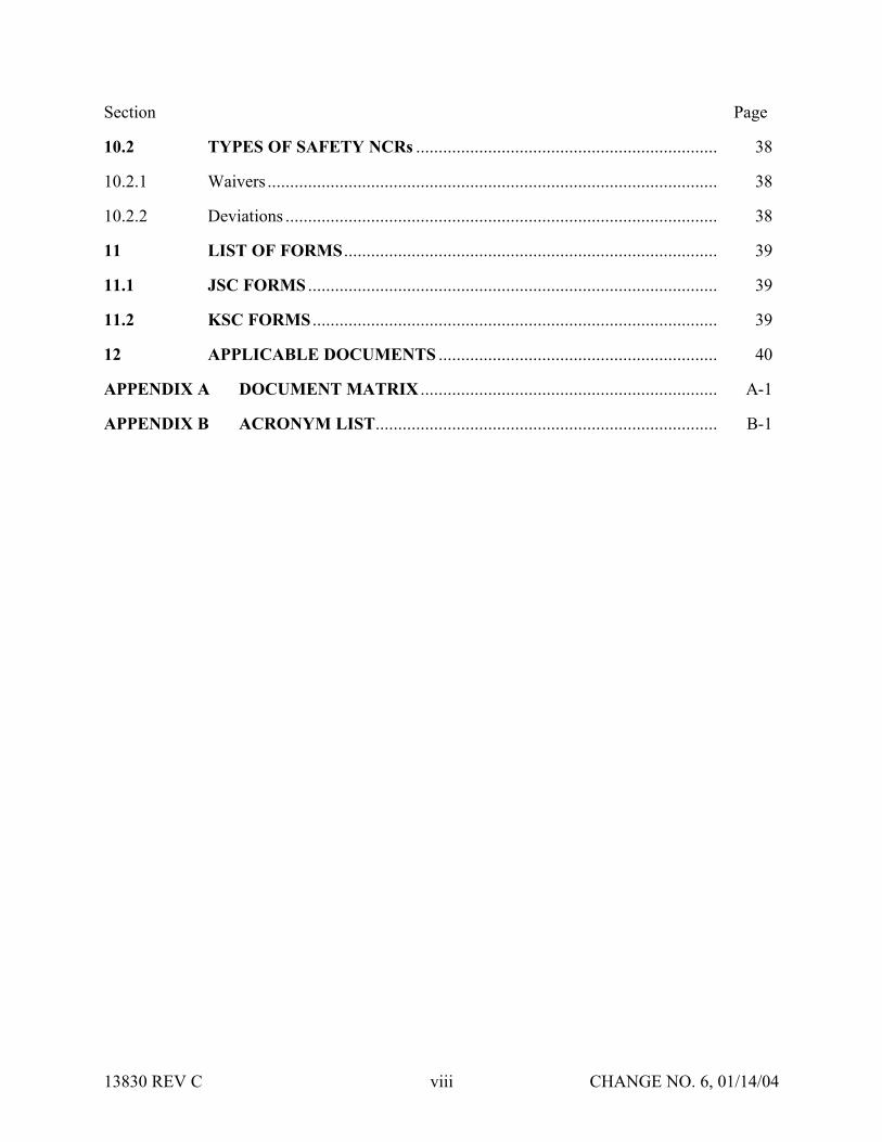
Section Page
102 TYPES OF SAFETY NCRs 38
1021 Waivers 38
1022 Deviations 38
11 LIST OF FORMS 39
111 JSC FORMS 39
112 KSC FORMS 39
12 APPLICABLE DOCUMENTS 40
APPENDIX A DOCUMENT MATRIX A-1
APPENDIX B ACRONYM LIST B-1
13830 REV C viii CHANGE NO 6 011404
SECTION 1 INTRODUCTION
Implementation of the payload safety process is the joint responsibility of the Payload Organization (PO) the flight operator Lyndon B Johnson Space Center (JSC) and the launchlanding site operator John F Kennedy Space Center (KSC)
The International Space Station (ISS) and Space Shuttle Program (SSP) safety policies and requirements for ISS and Shuttle payloads are specified in the current version of NSTS 17007ldquoSafety Policy and Requirements for Payloads Using the Space Transportation Systemrdquo and the current version of the NSTS 17007 ISS Addendum ldquoSafety Policy and Requirements for Payloads Using the International Space Stationrdquo In addition unique ground safety policies and requirements are specified in the current version of 45 SPW HB S-100KHB 17007 ldquoSpace Shuttle Payload Ground Safety Handbookrdquo These documents require the PO to conduct asystematic safety analysis and to document and submit a Safety Data Package (SDP) in support of safety reviews to be conducted by the flight operator (JSC) and the launchlanding site operator (KSC)
National Aeronautics and Space Administration (NASA) Headquarters has assigned the responsibility to review submitted payload safety documentation to the Space Shuttle and Space Station Program Directors at JSC and the Director of Safety and Mission Assurance at KSC The JSC Payload Safety Review Panel (PSRP) will assess the payload design and flight operations the KSC Ground Safety Review Panel (GSRP) will assess the Ground Support Equipment (GSE) design and ground operations These two panels were formed to accomplishthe following
bull Assure that PO interpretation of the safety requirements is consistent with NASA payload safety policy
bull Conduct safety reviews as appropriate during the development of the payload associated GSE and related operations
bull Evaluate hazard analyses and Noncompliance Reports (NCRs) bull Negotiate the resolution of safety issues involving design and operation to ensure compliance
with all applicable safety requirements bull Assess payload design features that have been implemented for controlling identified hazards
and the verification approach that confirms intended system performance
13830 REV C 1 CHANGE NO 6 011404
SECTION 2 PURPOSE
The purpose of this document is to define the payload safety review process in order to assist the ShuttleISS POs in documenting compliance with the payload requirements documents specified in section 1 Specifically this document accomplishes the following
bull Defines the safety reviews necessary to comply with the system safety requirements that are applicable to payload design flight operations GSE design and ground operations for both ISS and Space Shuttle
bull Identifies the required content of the SDP bull Describes preparation for and conduct of the safety review bull Establishes the timeline for data submittal and establishes the depth of detail required for the
various submittals bull Explains safety review process variations bull Defines the payload seriesreflight review process
13830 REV C 2 CHANGE NO 6 011404
SECTION 3 SCOPE
Data submittal requirements included herein apply to hardware being submitted to both the PSRP and the GSRP unless specified otherwise This document outlines the minimum data submittal requirements the PSRP and the GSRP reserve the right to request additional data as deemed necessary to support safety documentation
The objective of the safety review process is to review the payload GSE and operations for adequate safety implementation The mission success and any scientific objectives of the payload are the responsibility of the PO and are beyond the scope of this document and process
This document does not establish design requirements
31 APPLICABLE HARDWARE
This document applies but is not limited to the following payload hardware that fliesoperates on the Space Shuttle andor ISS during any mission phase (prelaunch launch ascent on-orbit entry landing or postlanding)
bull New Payload Hardware bull Existing (reflown and series) Payload Hardware bull Hardware Associated with Developmental Test Objectives (DTOs) Detailed Supplemental
Objectives (DSOs) Risk Mitigation Experiments (RMEs) Space Medicine Program (SMP) and Human Exploration and Development of Space Technology Demonstrations (HTDs) Experiment Hardware
The document also applies but is not limited to the following payload-related hardware
bull Government-Furnished Equipment (GFE) bull Airborne Support Equipment (ASE) bull GSE
32 EXPORT CONTROL
The PSRP complies with the United States export control laws and regulations as established by the US Department of Commerce in the Export Administration Regulations (EAR) and the US Department of State in the International Traffic in Arms Regulations (ITAR) The PSRP also complies with the Space Shuttle Programrsquos export control policy in NSTS 07700 Volume V and the ISSPrsquos export control policy in SSP 50223
13830 REV C 3 CHANGE NO 6 011404
Export control factors significantly into two areas of the payload safety review process
bull Distribution of Payload Data
bull Conduct of Safety Reviews
The PSRP Executive Secretary serves as the primary exporter of payload data to the ISS International Partners (IPs) and other foreign persons in support of the payload safety review process Payload data includes safety data packages hazard reports safety review presentation materials and other payload related information Specific export control data submittalrequirements for payload organizations are listed in section 4315 of this document
The PSRP Executive Secretary takes special precautions when conducting safety reviews for payloads under export control restrictions These precautions may include restricting attendance limiting presentation materials posting signs or conducting the review in a secure facility
13830 REV C 3A CHANGE NO 6 011404
SECTION 4 RESPONSIBILITIES OF THE PAYLOAD ORGANIZATION
The PO is responsible for assuring the safety of its payload and for complying with the safety requirements contained in the technical requirements documents cited in section 1 To this end the PO must accomplish the following
bull Perform a Safety Analysis bull Identify Hazards bull Document Compliance with the Safety Requirements bull Present the Documentation to the PSRPGSRP
41 SAFETY ANALYSIS
To meet the requirements of the current version of NSTS 17007 and NSTS 17007 ISS Addendum paragraph 301 the PO shall perform a safety analysis of the payload and GSE The analysis shall consider hardware design verification testing and flightground operations The safety analysis shall begin during the payload concept phase and shall be refined and expanded as the design matures For situations in which payload hardware will be installed orreconfigured on-orbit or in which the payload will be on-orbit for an extended time safety analyses shall consider the necessity of on-orbit verificationreverification of hazard controls
411 Level of Analysis
In order to identify the hazards applicable to a payload the PO shall conduct safety analyses both at the system and subsystem levels Each system and subsystem shall be evaluated to determinethe applicability of each technical safety requirement
Selection of subsystem groupings varies and any convenient grouping may be used The following is a suggested list of subsystems biomedical caution and warning cryogenic electrical environmental control human factors hydraulics materials mechanical opticalpressure systems propulsion pyrotechnics radiation and structures
For hardware developed for or provided to the PO the PO shall
bull Obtain the appropriate safety data from the supplier or conduct an independent safety analysis
bull Conduct a safety analysis of the interfaces between the subject hardware and other elements
412 Analysis Techniques
Depending on the complexity of the payload the PO should use established analytical techniques (eg preliminary hazard sneak circuit fault tree operational hazard and failure modes and effects analyses) to obtain the data necessary to complete present and support payload hazard reports
13830 REV C 4 CHANGE NO 6 011404
413 Safety Verifications for Payloads with Catastrophic Hazard Potential (Flight Only)
The current version of NSTSISS 18798 specifies data requirements to document the verification program for payload systemssubsystems that have catastrophic hazard potential An excerpt from this document is included below for convenience
Table 4-1 - NSTSISS 18798
All payload systems having catastrophic hazard potential for the orbiter or crew as a result of operations in or near the orbiter must use hardware and procedures that have been subjected to a rigorous verification program Verification programs normally require testing to verify adequate performance margins under all environmentalconditions (qualification testing) as well as demonstrating intended system performance on flight hardware Comprehensive system-level testing on payload flight hardware supported by qualification test on protoflight or flight type hardware are the preferred verification methods It is essential that payload system performance be verified from the input stimuli to the end function
Safety-critical system performance that cannot be verified by test shall be verified by independent parties using dissimilar analysis techniques whenever possible Single party analytical efforts can be used to verify performance only when the methodology is widely accepted and conservative margins are applied to the results
The payload organization must focus its attention to all parts of the payload verification program and orbiter interface verification activities to assure that the sub-elements of the total verification program are integrated into a comprehensive system verification effort that confirms the intended system performance When the use of ground test equipment(apparatus) is required to replace flight hardware functions verification methods shall be developed by engineering personnel independent from those designing the flight systemTest requirements procedures and test apparatus shall be derived from intended functional requirements rather than from the design and all items must be maintained under strict configuration control The payload organization is responsible for developing and presenting sufficient data to the PSRP [GSRP] to substantiate that the test requirements procedures and test apparatus will provide an adequate simulation in substitution for the end function
42 HAZARD IDENTIFICATION
The primary objectives of the safety review process are to identify the potential hazards applicable to a payload including its flight GSE and ground operations and to assure that the hazard controls and verifications (including on-orbit verificationreverification of hazard controls where applicable) are adequate and in compliance with the safety requirements To assist the PO in accomplishing these objectives appropriate safety terminology has been defined in the current version of NSTS 17007
Although not exhaustive the following is a list of some previously identified flight hazard groups that have been used on hazard reports collision contamination corrosion electrical shock explosion fire injury and illness loss of orbiter entry capability and inability to egress
13830 REV C 5 CHANGE NO 6 011404
The following are basic hazard groups applicable to ground operations structural failure of support structures and handling equipment collision during handling inadvertent release ofcorrosive toxic flammable or cryogenic fluids loss of habitablebreathable atmosphere inadvertent activation of ordnance devices ignition of flammable atmospherematerial electrical shockburns personnel exposure to excessive levels of ionizing or nonionizing radiation use of hazardousincompatible GSE materials inadvertent deployment of appendages working under suspended loads and rupture of composite epoxy overwrapped pressure vessels
43 DOCUMENTATION OF COMPLIANCE WITH THE SAFETY REQUIREMENTS
The safety analysis results shall be documented in the SDP which includes applicable payload hazard report forms (JSC Form 542B and JSC Form 1230) and presented to both the JSC PSRPand the KSC GSRP as described in this document Guidelines for completing the flight hazardreport forms and preparing the SDPs are found in JSC 26943 ldquoGuidelines for the Preparation of Payload Flight Safety Data Packages and Hazard Reports for Payloads Using the Space Shuttlerdquo current issue
For SDP preparation the PO is responsible for using the current version of all applicable forms and safety documentation The PO may verify current formsdocuments by contacting theExecutive Secretary to the PSRP or the Chairman of the GSRP These forms are listed in section 11
431 Data Submittals
Although there will be some duplication of material contained in data submittals prepared for PSRP and GSRP reviews each package serves a different purpose and must stand alone
Data submittals which may include SDPs and other supporting information (eg action item responses) should identify the flight on which the payload is manifested (if known) and be formally submitted in English to the Executive Secretary PSRP or the Executive Secretariat GSRP Data should be formally transmitted under the signature of the Program Manager
Safety review meetings are scheduled to be held approximately 45 calendar days after receipt of an acceptable SDP (ie an SDP that satisfies all the requirements in this document)
The SDP will be made available to the PSRPGSRP members and various other NASAcontractor technical and administrative personnel who support the Panels For ISS payloads this may include International Partner representatives to the PSRP
Payload safety data must be submitted electronically via the Internet using the Payload Safety Data Management System (DMS) located at the following URL
httppsrpjscnasagov
The DMS System Administrator (tel 281-483-9078) can provide information on acceptable software applications electronic addresses detailed login instructions and system procedures POs may also access the DMS via a hyperlink at the top of the Payload Safety homepage located at the following URL
13830 REV C 6 CHANGE NO 6 011404
httpwwwsrqajscnasagovpce
POs must obtain approval from the PSRP Executive Secretary or Executive Secretariat GSRP to submit flight or ground safety data respectively by alternate means or to submit supplementary data in hard copy format Hard copy submittals must be single-sided and sequentially paginated from the cover sheet to the last page of the package
Once the SDP has been electronically submitted the PO must send the transmittal lettersdocument signature pages and signed original Hazard Reports (HRs) to the appropriate Panel contact
Executive Secretary PSRPNASA Lyndon B Johnson Space Center
Mail Code NC4 2101 NASA Road 1
Houston TX 77058-3696
Executive Secretariat GSRP NASA John B Kennedy Space Center
Mail Code UB-F3 Kennedy Space Center FL 32899-0001
13830 REV C 6A CHANGE NO 6 011404
4311 Submittal of Proprietary Data
If proprietary data are submitted in the SDP the transmittal letter must include the following statement
This payload safety data package contains proprietary data on the following pages [listthe appropriate page numbers] [Insert name of the payload organization] acknowledges awareness and acceptance of the GSRP and the PSRPrsquos policies and methods of processing proprietary data [Insert name of the payload organization] also will provideany additional protective measures it deems necessary over and above that provided by the panels during meetings
The transmittal letter and the first page of the SDP must identify the specific pages that contain proprietary information Insert the word ldquoPROPRIETARYrdquo at the top and bottom of each pagethat contains proprietary data The word ldquoPROPRIETARYrdquo shall be in all capital letters in alarge font size and style that is easily discernible from the rest of the text
In addition to the proper submittal of proprietary information the PO should be aware of the following while attending PSRPGSRP safety reviews Technical Interchange Meetings (TIMs) and action item closure meetings
bull PSRPGSRP meetings are not conducted in secure facilities Thus when it is necessary torecess meetings (eg lunch and breaks) the POs will be responsible for protecting any proprietary data distributed during the meeting (other than that logged and distributed byNASA as part of the SDP)
bull If any proprietary data are to be presented or discussed during the meeting prior to the meeting the PO will notify the PSRP Executive SecretaryGSRP Chairman who will then make arrangements to monitor attendance close the doors and post a sign noting that accessto the meeting is controlled
bull The PO will be responsible for retrieval and disposition of any proprietary material distributed at the meeting (other than that logged and distributed by NASA as part of the SDP) with the exception that two copies of proprietary material distributed by the PO at the meeting will be retained by the PSRPGSRP in a protected file
When the PSRPGSRP receives proprietary data included in the SDPs such data will be handledin a manner that will protect the interests of the PO These procedures include trackingdistributed materials protecting files and restricting reproduction In order to exercise reasonable care in protecting proprietary data in connection with the payload safety review process NASA will ensure that proprietary data are distributed only to persons who have a needto review such data in support of panel functions Furthermore distributed data that is returned to the PSRP Executive SecretaryGSRP Chairman after use will be destroyed via the NASAsecure disposal process
13830 REV C 7 CHANGE NO 6 011404
The protection of material marked ldquoPROPRIETARYrdquo creates an added burden on thePSRPGSRP review support system so the PO should mark only those items that are proprietary The PO should coordinate with the PSRP Executive SecretaryGSRP Chairman to explore such alternatives as providing the proprietary material in a separate package when it is a very small portion of the overall SDP If a separate proprietary briefing package (not containedin the SDP) is to be presented to the PSRPGSRP during the review the PO shall provide at least20 copies of such material for distribution at the review
If the PO discovers that some portion of the SDP marked ldquoPROPRIETARYrdquo is no longerconsidered such the PO must inform the PSRP Executive Secretary andor the GSRP Chairmanin writing
4312 Submittal of Copyrighted Data
Payload organizations are hereby informed that payload documentation submitted to NASA must be reproduced and distributed to the members of the PSRPGSRP and to associated technicalsupport personnel Accordingly copyrighted data shall not be included in the submitteddocumentation unless the PO 1) identifies such copyrighted data and 2) grants to theGovernment or acquires on behalf of the Government a license to reproduce and distribute the data to these necessary recipients
4313 Submittal of Translated Data
For all documents submitted by the PO to the PSRPGSRP that have been translated intoEnglish the English translation shall be the official document
4314 Submittal of Toxicological Data for SSP and ISS Payloads (Flight Only)
The ShuttleISS payload safety review process requires biomedical safety assessments of potentially hazardous materials such as chemicals microorganisms and radioisotopes In order for these assessments to be available for the safety reviews the JSC Toxicology Group requires POs to submit test sample data substantially in advance of the safety reviews See JSC 27472 ldquoRequirements for Submission of Test Sample-Materials Data for Shuttle Payload Safety Evaluationsrdquo current issue for the timeline and data requirements for these early submittals The PO must attach both the data submitted to JSC Toxicology Group and the JSC response (when available) to the applicable hazard report that is a part of the SDP Should toxicology submittals involve proprietary data see section 4311
4315 Submittal of Export Control Data (Flight Only)
The export control data submittal requirements in sections 43151 and 43152 apply to USpayload organizations only IP payload organizations are not required to provide the US export control classification of their safety data packages In the event that an IP SDP requires a USexport control classification NASA export control resources will be used to classify the SDP
13830 REV C 8 CHANGE NO 6 011404
43151 ISS Payloads
Distribution of ISS payload safety data packages to the ISS IPs is a standard part of the payload safety review process
The PO must identify the export control classification of the SDP payload data in its transmittal letter The first page of the SDP must also identify the export control classification of the data
The PSRP Executive Secretary will not distribute an SDP with an unknown export controlclassification to the IPs Safety reviews may be delayed or cancelled for ISS payloads with unresolved export control issues
The POrsquos safety review presentation materials must have the same export control classification as the SDP submitted for review or a less restrictive export control classification
43152 Shuttle Payloads
Distribution of Shuttle payload safety data packages to the ISS IPs is not a standard part of the payload safety review process
Shuttle payload safety data packages are not distributed to the IPs unless the PSRP identifies a specific need to do so If a need is identified the PSRP Executive Secretary will work with the PO and the SSPrsquos export control resources to obtain the export control classification of the SDP
The PO may include the export control classification of the SDP payload data in its transmittalletter and on the first page of the SDP if the classification is known prior to SDP submittal
432 Hazard Reports
The purpose of the hazard reports is to document the POrsquos safety assessment in a manner that reflects how the payload design demonstrates compliance with the safety requirements The hazard reports are used as a method to systematically assess compliance with the safety requirements
The flight SDP submittal must contain all flight hazard reports the ground SDP submittal mustcontain all ground hazard reports Each hazard report must be signed and dated by the payloadprogram manager prior to submittal Hazard reports shall be prepared on JSC Form 542B JSCForm 542B-1 or JSC Form 1230 (see section 11) or an equivalent form that contains all information required on the JSC forms Section 7 organized by area of design identifies minimum support data for flight hazard reports JSC 26943 contains guidelines for preparingpayload flight hazard reports
13830 REV C 8A CHANGE NO 6 011404
Following any technical discussion the PSRPGSRP Chairman will provide a disposition for each hazard report This disposition may take one of the following forms 1) approved aswritten 2) approved with modification 3) approved with an action to be performed by the PO andor PSRPGSRP and 4) not approved
The PO is responsible for retaining and maintaining the original hazard reports after approval
44 SAFETY REVIEW PRESENTATION
The PO should be prepared to present information submitted in the SDP to the appropriate safety panel during scheduled reviews (see sections 611 and 612) During reviews the PO shouldprovide briefing chart handouts sufficient for the number of people expected to attend the review
13830 REV C 9 CHANGE NO 6 011404
SECTION 5 SAFETY REVIEW OVERVIEW
51 LOCATION
Safety reviews for payload design and flight operations are usually conducted at JSC The safetyreviews for GSE design and ground operations will normally be conducted at KSC The PO shall coordinate the timing of the PSRP reviews with the PSRP Executive Secretary The PO shall coordinate the timing and location of the GSRP reviews with the GSRP Chairman
52 INITIAL CONTACT MEETING
The PO may receive initial contact safety briefings by the JSC and KSC safety representatives The JSC briefing normally held during the first integration meeting at JSC should be scheduledby contacting the Payload Integration Manager (PIM) at JSC For ISS payloads contact the ISSPIM The KSC briefing is usually held in conjunction with the first Ground Operations Working Group (GOWG) meeting which is scheduled through the Launch Site Support Manager Integration Manager (LSIM) at KSC
The briefing includes an overview of the technical and system safety requirements to be met by the PO plus instructions for conducting the safety reviews The PO should provide a schedule ofpayload milestones and request a phase 0 or phase I safety review when the payload design concept has been developed
53 TYPES OF MEETINGS
Safety reviews may take place in person via teleconference or by correspondence Review meetings may be formal or out-of-board as deemed appropriate by the Panel Chairman
bull Formal Meeting Formal meetings constitute a gathering of the safety review panel representatives of the PO and the appropriate supporting technical staff
bull Out-of-Board Meeting Out-of-board meetings do not require the full safety panel Attendees may include the Panel Chairman Safety representative(s) representatives of the PO and others necessary to address the issues that may be involved
bull Safety TIM The review panel andor associated technical staff may convene upon request in order to assist in interpreting safety requirements or to coordinate safety analysesissues prior to safety reviews Requests for flight safety TIMs should be coordinated with the PSRP Executive Secretary Requests for Ground Safety TIMs should be coordinated with the GSRP Chairman Material to be addressed during the TIM should be provided 14 calendardays prior to the TIM
bull Splinter Meetings Splinter meetings may be held concurrently with a safety review to discuss detailed technical concerns
13830 REV C 10 CHANGE NO 6 011404
54 PAYLOAD CATEGORIES
Traditional payload safety compliance assessment is accomplished using a phased safety review process (phases 0 I II III) that corresponds to the hardware conceptual preliminary and critical design review phases and verificationvalidation of the payload (see section 6) Successful completion of each safety phase is documented by SDPHR submittals to and approval by the PSRPGSRP
To streamline this process the PSRP has implemented procedures and data requirements to minimize formal PSRP review time for payloads with routine hazardsstandard controlsverifications This allows the PSRP to concentrate review time on payload systems withthe highest hazard potential ldquomust-workrdquo functions andor nonstandard controls and verification methods POs may document routine hazards and standard controls and verifications on the JSC Form 1230 ldquoFlight Payload Standardized Hazard Control Reportrdquo
Based on the phase I SDP new payloads are categorized by the PSRP into one of three categories of complexity (basic intermediate or complex) with respect to hazard potential as shown in Table 5-1 below The review process is then tailored to the complexity of the payload design and adequacy of documentation In addition the process permits all payloads to document standard hazards that have standard controls and verifications on JSC Form 1230 which may be approved by the PSRP without a formal PSRP meeting Details concerning basicand intermediate categories are contained in sections 541 and 542 respectively Complexpayloads use the review process detailed in section 6 Reflown and series payloads use thereview process outlined in section 9
Table 5-1 - PAYLOAD CATEGORIES
PayloadCategory
Defined Hazards
Basic The only hazards identified are ldquostandardrdquo as specified on the JSC Form 1230 The appropriate hazard controls are found on JSC Form1230
Intermediate 1) The payload has ldquouniquerdquo hazards (ie hazards not found on the JSC Form 1230) but has controls and verification methods that have been historically accepted by the PSRPOR
2) The payload has ldquostandardrdquo hazards (ie hazards identified on the JSC Form 1230) but uses controls and verification methods other than those identified on the JSC Form 1230
Complex The payload has unique hazards with hazard controls that are
a Active ldquomust workrdquo functions such as electromechanical or pyrotechnic separation systems or actuatorsmechanisms providing structural load paths
OR b Nonstandard or have nonstandard verification methods that
depart from historically accepted techniquesOR c Operationally complex requiring flight or ground personnel
intervention to assist in controlling the hazard
13830 REV C 11 CHANGE NO 6 011404
If after a payload category has been assigned the PO a) identifies previously undefined hazards or b) implements design changes that may create new hazards the PO must submit a revisedSDP which may result in a reclassification of the payload category
541 Review Process for Basic Payloads (Flight Only)
Basic payloads (see Table 5-1 above) have a very low level of complexity which may allow the payload to complete the safety process out of board However the PO will submit an SDP that will document the applicable hazards controls and verifications Submittal will follow the standard procedure detailed in section 431 and approval may be obtained without a meeting The following data are required for the simplified SDP for hardware design and flight operations
bull Brief description of the hardware design and flight operations with schematics and block diagrams as appropriate
bull Summary of the safety analysis results that documents compliance with the design verification and applicable on-orbit verificationreverification requirements for the identified standard hazards
bull Documentation of all applicable hazards controls and verifications on hazard report(s) (eg JSC Form 1230Form 542)
bull Certificate of Payload Safety Compliance (JSC Form 1114A) signed by the ProgramManager
542 Review Process for Intermediate Payloads (Flight Only)
In addition to the standard hazards found in Basic payloads the Intermediate payload has unique hazards that have standard controls and verification methods (including applicable on-orbit verificationsreverifications) that have been historically accepted by the PSRP Intermediate category payloads should require one or two reviews of the unique hazards but the basic hazards may be addressed on a Form 1230 and approved out of board The PSRP will determine the need for a second review for unique hazards at the completion of the first review The determination will be based primarily upon the completeness and quality of the unique hazard reports Requirements for SDP submittal are the same as those stated in section 431
55 SCHEDULE OF REVIEWSPHASES
The schedule for formal phase 0 I and II payload safety reviews generally relates to the payload development schedule Phase 0 is held during the concept phase or at the start of payload design Phase I is near the Preliminary Design Review (PDR) phase II is near the Critical Design Review (CDR) The PO should set the review schedule to obtain maximum benefit to payloaddevelopment based on the results of the safety reviews
ISS payloads may include multiple major systems or components each working to a uniqueschedule These may be individually baselined and categorized (see section 54) which allows them to progress through the payload safety process in accordance with their own schedule (see section 82)
13830 REV C 12 CHANGE NO 6 011404
Phase III is associated with completion of payload safety verifications andor the start of ground processing When establishing a timeline for phase III the PO should allow enough time to closepotential issues that may result from a phase III review The timing and completion of the phase III review and safety certification are critical to the launch schedule The flight and ground phaseIII completion requirements restated below are in the current version of NSTS 17007 and NSTS 17007 ISS Addendum and apply to all payloads
The JSC and KSC Phase III safety review and ground safety certification must be completed 30 days prior to delivery of the payload ASE and GSE to the launch sitehellip
If any verification items remain open on the flight hazard reports the PO must provide rationale to support the safety of starting ground processing with these items open The rationale is to be submitted to both the PSRP and GSRP The PSRP will review the rationale and provideconcurrence to the GSRP
To schedule KSC Ground safety reviews contact the GSRP Chairman to schedule JSC Flight safety reviews contact the PSRP Executive Secretary (see section 431)
56 SAFETY REVIEW COMPLETION
561 Documentation of Phase Completion
During a formal meeting the Panel Chairman will make an official announcement that the safety phase is complete or incomplete (open) This announcement will be recorded and distributed bythe PSRPGSRP in the official meeting minutes Incomplete phases are usually attributable to overdueopen action items or unsigned (open) hazard reports The PSRPGSRP will issue officialcorrespondence to document closure of open action itemssignature of open hazard reports thatoccurs after the phase review The correspondence that closes the last open action itemhazardreport for that phase will include a statement that the safety phase is considered complete
For out-of-board reviews safety review process completion will be documented by formal correspondence
562 Completion Criteria for Phase I II and III
Successful completion of phase I and II reviews is accomplished by obtaining approval (Panel Chairmanrsquos signature) of hazard reports at the appropriate phase level and closure of applicable phase III action items
After submission of all required data the criteria for successful completion of the safety review process at the phase III level for both flight and ground reviews are as follows
bull All payload hazard reports are signed by the payload Program Manager and the Panel Chairman at the phase III level
bull All NCRs are approved bull Safety review action items are formally closed in the safety review meeting minutes or
documented closed in separate correspondence bull A signed Certificate of Ground Payload Safety Compliance provided to the GSRP (for phase
III ground safety)
13830 REV C 13 CHANGE NO 6 011404
Approval of the phase III safety data by the PSRP and GSRP is with the understanding that the data represent the actual design and operations of the payload Should safety issues arise after the safety process is complete the safety panels reserve the right to request additional data deemed necessary to reassess the payload
563 Completion Criteria for SeriesReflight
The criteria for successful completion of a series or reflight safety review is that all data required by section 9 Reflown and Series Payload Hardware have been submitted and approved
57 POST PHASE III SAFETY ACTIVITY
571 Certificate of Flight Payload Safety Compliance
The PO must present a signed Certificate of flight Payload Safety Compliance to the PSRP Executive Secretary no later than 10 days prior to the Flight Readiness Review (FRR)
572 Configuration Control
When changes to the design configuration or operations of the payload are required subsequent to phase III the PO shall assess those changes for possible safety implications including the effect on all interfaces The assessment shall be forwarded to the PSRPGSRP for review andapproval If the change has ground safety implications it must be reviewed with the KSC panel prior to proceeding with ground processing New or revised hazard reports and support datashall be prepared where applicable and submitted for approval as indicated in section 431 The need for delta phase III safety reviews will be determined by the PSRPGSRP Chairman Satisfactory completion of these activities is mandatory prior to the start of affected ground activities or launch
Any test failures anomalies or accidents involving payload flight hardware or software that occurs between the completion of phase III and launch must be promptly reported to the PSRPGSRP Safety impacts if any should be identified
573 Verification Tracking Log
Open verification items must be tracked on a flight or ground safety Verification Tracking Log (VTL) (see section 11)
bull Flight Safety From Phase III until L-60 days the PO shall update and provide the VTL to the PSRP Executive Secretary once a month From L-60 days until launch the PO shall provide a weekly update to the VTL All VTL open items must be closed no later than 4PM Central time on the last business day prior to launch Items that cannot be closed at this time will require the transmission of a facsimile closing the open VTL items to the Mission Evaluation Room (MER) at NASA JSC no later than L-6 hours Contact the PSRP Executive Secretary for MER delivery instructions
bull Ground Safety The initial submittal of the ground safety VTL is required with the phase III ground SDP Following the completion of the phase III review the ground safety VTL shall be updated monthly prior to hardware arrival at KSC If there are open flight verifications
13830 REV C 14 CHANGE NO 6 011404
that are constraints to ground processing the PO must also include those items of the flight VTL After the delivery of the payload ASE or GSE to the launch site the safety VTL(s) shall be updated at least weekly More frequent updates to the safety VTL(s) may be required if the open items must be closed to allow work to continue
574 Documentation of Safety Process Completion
Final flight safety approval is documented by the PSRP Chairmanrsquos signature on the Certificateof Flight Readiness (CoFR) for the planned flight
Final ground safety approval is documented by a letter from the KSC Director Safety Assurance to the KSC Director Customer Service Space Station and Shuttle Payloads Processing statingthat the Ground Safety Review Process has been completed and the payload may begin ground processing
13830 REV C 15 CHANGE NO 6 011404
SECTION 6 SAFETY PROCESS
61 GENERAL
611 Preparation
In preparation for a phase safety review the PO will submit an SDP as indicated in section 431 If phase reviews are combined (eg a phase III review) the SDP shall include the datarequirements that apply to all the appropriate phases The depth and number of the plannedreviews are dependent on the complexity technical maturity and hazard potential of the payload and may be modified by the Panel Chairman in conjunction with the PO
The PO should provide sufficient technical support personnel to answer questions posed by the PSRPGSRP in support of the agenda items
Listed below are general agenda topics for safety review meetings These insure that the safety review meetings proceed smoothly and contain the necessary information to facilitate the review
612 General Meeting Agenda Guidelines
The PO should coordinate all meeting agenda with the PSRP Executive Secretary or the GSRP Chairman prior to the safety review meeting and provide the final agenda in advance The fundamental elements of all Safety Review Meeting Agenda are as follows
a Introduction of the Meeting and Participants by the JSC Safety Reliability and Quality Assurance (SRampQA) Payload Safety Engineer (PSE)
b Opening Remarks by Chairman and the Payload Program Manager
c Discussion of Pre-Review Activity Led by the PSE
d Program-level Overview (including areas of responsibility)
e Program Milestone Schedule Provide the Program Milestone Schedule includingbut not limited to
(1) design stages and reviews
(2) hardwaresoftware build status
(3) testing and verification activities
(4) delivery integration and launch activities and
(5) safety review dates
f Mission Objectives including overview of mission objectives and general criteria for a successful mission
13830 REV C 16 CHANGE NO 6 011404
g SystemSubsystem Technical Presentation Overview including enough information to allow the PSRPGSRP to gain a general technical understanding of the systemsinvolved in the payload operations Highlight any design changes since the previous safety reviews
h Operations Overview describing planned operations and known contingencies Plan to discuss detailed operations that relate to payload safety in conjunction with the appropriate hazard report presentation Highlight any operations changes made tothe operations that impact the safety of the payload since the previous review
i Safety Assessment Summary including safety assessments performed to identify hazards any failures or anomalies that occurred after development testing and the corrective actions Present responses to agreements and formal action items including a summary of open action items and associated plans for closure Provide sufficient information to demonstrate that a comprehensive hazard analysis has been performed Provide an overview of hazards and how they relate to the hazard reports and discuss safety-related items that are not reflected in the hazard reports
j Phase-specific Topics Additional phase-specific topics for the agenda should be drawn from the data that are required to be included in the SDP for that phase (see sections 621 631 641 and 651) If not included as one of the general agendatopics these data should be addressed as separate agenda items
k Hazard Report Presentation Unless otherwise agreed to by the PSRPGSRPpresent all hazard reports in full associated noncompliancereportswaiversdeviations previously assigned action itemsagreements that involved modification of hazard reports and associated action itemagreement responses
l Action Item Review Both the PO and the PSRPGSRP will review and agree toactions and due dates assigned during the course of the safety review to ensure that there are no misunderstandings These action items will be printed and signed during the review
m Closing Comments Payload Program Manager and Panel
62 PHASE 0 SAFETY REVIEW
The optional phase 0 safety review is provided as a service to the PO The objectives of the meeting are to
bull Assist the PO in identifying hazards hazard causes and applicable safety requirements early in the development of the payload
bull Adequately describe the hazard potentialbull Answer questions regarding the interpretation of the safety requirements or the
implementation procedures of this documentbull Provide guidance to the PO for preparing the safety data required for subsequent safety
reviews
13830 REV C 17 CHANGE NO 6 011404
621 Phase 0 Data Requirements
The following data are required for the phase 0 SDP and must be submitted as stated in paragraph 431
a For payload design and flight operations
(1) Conceptual payload description (including subsystems) and missionscenario
(2) Description of safety-critical subsystems and their operations
(3) Flight hazard reports (JSC Form 542BForm 1230)
b For GSE design and ground operations
(1) Conceptual payload description and brief mission scenario
(2) Conceptual GSE description and operations and description of payload design that is safety critical during ground operations
(3) Ground operations scenario
(4) Ground hazard reports (JSC Form 542B)
The description of the payload and its operation must be of sufficient detail to permit identification of all subsystems that may create hazards Emphasis should be given to thosesubsystems that store transfer or release energy The descriptions of the safety-critical subsystems must be of sufficient detail to identify the hazards in terms consistent with the conceptual design In addition the PO shall address tentative plans for any flight operation (eg extravehicular activity reverification of hazard controls) or ground operation that would require personnel certification to perform hazardous procedures
622 Phase 0 Hazard Reports
The purpose of a phase 0 hazard report is to document and scope the specific hazards identified It is intended to be a working document for discussion and critique at the phase 0 safety review and will not require signatures A hazard report must be prepared for each unique hazardidentified in the safety analysis The hazards contained on the phase 0 hazard report must reflect the payload conceptual design and operations existing at the time of the phase 0 review For phase 0 the PO may identify hazard controls verification methods or status of verifications
63 PHASE I SAFETY REVIEW
The purpose of the phase I safety review is to obtain PSRPGSRP approval of the updated safety analysis that reflects the preliminary design and operations scenario of the payload At this pointthe PO shall present a refined safety analysis that identifies all hazards and hazard causes inherent in the preliminary design evaluates all hazards for means of eliminating reducing or controlling the risk and establishes preliminary safety verification and on-orbit verificationreverification methods The PO shall provide a preliminary identification of the payload interfaces and of the hazards presented by these interfaces
13830 REV C 18 CHANGE NO 6 011404
631 Phase I Data Requirements
The following data are required for the phase I SDP and must be submitted as stated in paragraph 431
a For payload design and flight operations
(1) Updated payload description (including subsystems) and mission scenario
(2) Updated descriptions of safety-critical subsystems and their operations including schematics and block diagrams with safety features inhibits and controls identified Identify any safety-critical subsystems that are computer controlled and identify the functional architecture associated with that computer control
(3) Updated and additional flight hazard reports (eg JSC Form 542BJSC Form 1230) including appropriate support data (see section 7) For payloads thathave catastrophic hazard potential document the verification programoutlined in NSTSISS 18798
(4) A summary list (in the payload description) of orbiter- andor ISS program-provided critical services and an explanation (in the appropriate hazard reports) of the orbiter andor ISS services used to control andor monitorpayload hazards (NSTS 17007 and NSTS 17007 ISS Addendum current version)
(5) For ISS payloads a presentation of the Fire Detection and Suppression (FDS) implementation approach For sub-rack payloads the PO shall address the integrated system approach (using sub-rack services andor ISS services) to fully define the FDS implementation strategy In addition submit JSC Form 1428 to document methods and verifications used to detect and suppress a fire event for each payload volume
(6) Discussion of design features supporting verificationreverification of hazard controls on-orbit and associated constraints
(7) A tabulated list of tentative toxic materials and support data per JSC 27472(see section 4314)
(8) A list of all battery types their uses manufacturer and applications
(9) A preliminary description of all pyrotechnic devices and their functions
(10) Preliminary on-orbit maintenance safety assessment as outlined in NSTSISS 18798
b For GSE design and ground operations
(1) Updated payload description and brief mission scenario
13830 REV C 19 CHANGE NO 6 011404
(2) Updated descriptions of GSE payload subsystems that present a potential hazard during ground processing and their ground operations Schematics and block diagrams with safety features and inhibits identified should be included Design data for hazardous systems (pressure lifting etc) shall be summarized in a matrix Contact the GSRP Chairman for sample formats
(3) Updated ground operations scenario including postflight ground operationsat the primary alternate and contingency landing site The scenario should highlight unique payload requirements at the launch pad such as continuous power through a T-0 umbilical
13830 REV C 19A CHANGE NO 6 011404
(4) Updated ground hazard reports (JSC Form 542B) including appropriatesupport data
(5) Ordnance data required by the current version of KHB 17007 Appendix D
(6) Estimated KSC on-dock arrival date
632 Phase I Hazard Reports
The PO shall prepare phase I hazard reports for each hazard identified as a result of the safety analysis for the preliminary design and operations scenario of the payload Hazard reports shallbe added to or deleted from those agreed to during phase 0 to reflect the updated safety analysis Rationale for deleting a hazard agreed upon at phase 0 shall be presented during the phase I review
For phase I the PO shall identify hazard controls for each hazard cause identified at phase 0 A direct correlation between each hazard cause and the corresponding hazard control(s) must be clearly shown on the report Sufficient supporting information detailing each hazard control must be provided
Verifications should include the types of tests analyses inspections or procedures to be used to verify each hazard control including all orbiter- or ISS-provided services or interfaces both prelaunch and on-orbit A direct correlation between each verification method and the corresponding hazard control must be clearly shown on the report Each verification item should be independent and have a designator that allows for individual tracking of verification status
Manufacturingassembly proceduresprocesses that are critical in controlling hazards that cannot or will not be verified by subsequent inspection or test must be verified during the manufacturingassembly process An independent verifier as specified by the PO shall attest toproper completion of the procedureprocess Critical proceduresprocesses which require special monitored verification (Mandatory Inspection Points [MIPs]) shall be identified in preliminary fashion (NSTS 17007 and NSTS 17007 ISS Addendum current version)
If available the PO should provide a tentative schedule for completion of each verification taskand correlate with the integration schedule
64 PHASE II SAFETY REVIEW
The purpose of the phase II safety review is to obtain panel approval of the updated SDP that reflects the CDR-level design and operations scenario of the payload The phase II safety analysis identifies all hazards and hazard causes defines and documents implementation of a means for eliminating reducing or controlling the risks and documents finalized specific safety verification and on-orbit verificationreverification methods (test plans analysis and inspection requirements etc) Payload interfaces mission and ground operations procedures and timelines that were not addressed during the phase I safety review shall be assessed for safety hazards The payload interfaces to be assessed shall include those between the Shuttle andor ISS and the payload and among the various components that make up the payload (the spacecraft upper stages space platforms pallets experiments ASE ancillary flight equipment GSE KSC Facilities GFE etc) Newly identified hazards shall be documented in additional hazard reports For this review the PO should provide the estimated KSC on-dock arrival date
13830 REV C 20 CHANGE NO 6 011404
641 Phase II Data Requirements
The following data are required from the PO for phase II and must be submitted as stated in paragraph 431
a For payload design and flight operations
(1) Updated payload description (including subsystems) and mission scenario
(2) Updated descriptions of safety-critical subsystems and their operations including schematics and block diagrams with safety features and inhibits identified Provide electrical schematics that clearly identify the requirednumber of independent inhibits controls and monitoring provisions Present a summary of the test and analytical efforts required to verify the intended performance of all safety-critical hardware For a computer-based control system that is used to prevent criticalcatastrophic hazards provide the following datadescriptions bull Functional architecture bull Expected interactions bull Results of unexpected interactions bull Protections for common cause failures bull Development process for databases hardware software and
hardwaresoftware (3) Updated and additional flight hazard reports (eg JSC Form 542BJSC
Form 1230) including appropriate support data (see section 7) For payloads that have catastrophic hazard potential document the verification program outlined in NSTSISS 18798
(4) Updated summary list and explanation of orbiter- andor ISS-provided critical services
(5) For ISS payloads an update of the FDS implementation approach Include information on use of forced air flow wire derating circuit protection materials usage parameter monitoring (fan speeds temperatures currentetc) and responses to an out-of-limit condition and suppression approach For sub-rack payloads the PO shall address the integrated system approach (using sub-rack services andor ISS services) to fully define the FDS implementation strategy Updated JSC Form 1428 to reflect specific test (or analysis) procedures to be used along with the schedule for completion of FDS verification tests analyses or inspections
13830 REV C 21 CHANGE NO 6 011404
(6) Verification methods associated with hazard controls that require on-orbit verification andor reverification and the applicable approach (include rationale constraints and detailed methodology)
(7) An updated tabulated list of planned toxic materials and support data per JSC27472 (see section 4314) Updates should include changes in testmaterials changes in test conditions and any alternate test materials
(8) Updated list of all battery types their uses manufacturer and applications
(9) A list of all pyrotechnic devices their functions chemical composition critical components inspection plan verification plan and aging degradation evaluation plan
(10) List of hazard controls that require crew procedures andor training
(11) A record of test failures anomalies and accidents involving qualification or potential flight hardware Include a safety assessment for items which may affect safety
(12) The status of all action items assigned to the PO during phase I
(13) Detailed on-orbit maintenance safety assessment as outlined in NSTSISS 18798 Identify maintenance activities safe access areas and reverification of safety critical features
b For GSE design and ground operations
(1) Updated payload description and brief mission scenario
(2) Updated descriptions and matrices of the GSE the payload subsystems that present a potential hazard during ground processing and their ground operations Include updated schematics and block diagrams with safety features and inhibits identified Electrical schematics must show all payloadGSE grounding
(3) Updated ground operations scenario including postflight ground operations at the primary alternate and contingency landing sites
(4) Updated and additional ground hazard reports (JSC Form 542B) includingappropriate support data
(5) Updated ordnance data required by the current version of KHB 17007 Appendix D
(6) Updated KSC on-dock delivery date
(7) Specific engineering drawings and stress analyses of subsystems whenrequested by the GSRP Chairman
(8) A list of safety-related failures and mishaps that have occurred
13830 REV C 22 CHANGE NO 6 011404
(9) The status of all action items assigned to the PO during phase I
(10) A list of technical operating procedures that will be used at KSC with apreliminary designation as to which ones are considered hazardous
13830 REV C 22A CHANGE NO 6 011404
642 Phase II Hazard Reports
The PO shall prepare the phase II hazard reports by revising the phase I hazard reports to reflectthe completed payload design and flightground operating procedures If the payload designchanges from phase I to phase II so that a phase I hazard report may be deleted present a brief statement of rationale for deleting the report in the phase II SDP The GSRPPSRP willdisposition the hazard reports
Address all critical proceduresprocesses including the plan for verification Verifications shall refer to specific test (or analysis) procedures and summarize passfail criteria to be used Specifythe schedule for the completion of each specific verification test analysis or inspection
65 PHASE III SAFETY REVIEW
The purpose of the phase III safety review is to obtain PSRPGSRP approval of the SDP and safety compliance data that reflects the safety verification findings The focus of this review is to assess safety verification testing and analysis results If verifications critical for establishing the acceptability of the fundamental design of the payload for safety are not completed prior to the phase III review then subsequent reviews may be required prior to hazard report approval All verifications that are open at the time of the phase III SDP submittal must be included on the safety VTL Items listed on the VTL should be planned open work items such as groundprocessing at KSC
651 Phase III Data Requirements
The following data are required for the phase III SDP and must be submitted as stated in paragraph 431
a For payload design and flight operations
(1) Final as-built payload description (including subsystems) and mission scenario
(2) Updated descriptions that define the final configuration of the safety-critical subsystems and their operations including schematics and block diagramswith the as-built payload safety features and independent inhibits controls and monitoring provisions identified Address applicable features andconstraints relating to on-orbit verificationreverification of hazard controls
For a computer-based control system that is used to prevent criticalcatastrophic hazards provide verifications for the following bull Functional architecture bull Expected interactions bull Results of unexpected interactions bull Protections for common cause failures bull Flight article databases hardware software and hardwaresoftware
operate as designed
13830 REV C 23 CHANGE NO 6 011404
(3) Updated (and additional if required) flight hazard reports including support data that reflect the final configuration of the as-built payload and planned use For payloads that have catastrophic hazard potential document theverification program outlined in NSTSISS 18798
(4) Final summary list and explanation of orbiter- andor ISS-provided critical services
(5) For ISS payloads a finalized FDS implementation approach Include information on use of forced air flow wire derating circuit protectionmaterials usage parameter monitoring (fan speeds temperatures currentetc) and responses to an out-of-limit condition For sub-rack payloads the PO shall address the final integrated system approach (using sub-rack services andor ISS services) to fully define the FDS implementation strategy Final JSC Form 1428 to summarize the results of the completedtests analyses andor inspections and refer to particular test reports by document number title and date
(6) Updated (and additional if required) verification methods associated with hazard controls that require on-orbit verification andor reverification and the applicable approach (include rationale constraints and detailed methodology)
(7) A final tabulated list of toxic materials and support data per JSC 27472 (see section 4314) including additions and changes in test materials changes in test conditions and any alternate test materials
(8) A final list of all battery types their uses manufacturer and applications
(9) A final list of all pyrotechnic devices installed or to be installed on the payload The list will identify for each cartridge the function to be performed the part number the lot number and the serial number
(10) Updated list of hazard controls that require crew procedures and or training
(11) An updated record of test failures anomalies and accidents involving qualification or potential flight hadware or baselined flight software if the software is used for hazard control Include a safety assessment for items which may affect safety
(12) The status of all action items assigned to the PO through phase II
(13) Payload Flight Safety VTL (JSC Form 764)
13830 REV C 24 CHANGE NO 6 011404
(14) Identification of flight safety noncompliances Flight safety NCRs must be approved as either a waiver or a deviation before the phase III safety review can be completed A signed copy of each approved safety waiver andor deviation shall be included in the phase III SDP attached to the appropriate hazard report
(15) Finalupdated on-orbit maintenance safety assessment as outlined in NSTSISS 18798
b For GSE design and ground operations
(1) Final as-built payload description and brief mission scenario
(2) Updated descriptions and matrices defining the final configuration of the GSE the payload subsystems that are potentially hazardous during ground processing and their ground operations Include updated schematics andblock diagrams with the as-built safety features and inhibits identified
(3) Updated and finalized ground operations scenario including postflight ground operations at the primary alternate and contingency landing sites
(4) Updated and additional ground hazard reports including support data thatreflect the final configuration of the as-built GSE and planned payloadGSE use
13830 REV C 24A CHANGE NO 6 011404
(5) Updated and finalized ordnance data required by the current version of KHB 17007 Appendix D
(6) Updated and finalized KSC on-dock delivery date
(7) Specific engineering drawings and stress analyses of subsystems whenrequested by the GSRP Chairman
(8) A summary and safety assessment of all safety-related failures and accidents applicable to payload processing test and checkout Identify impact to theSpace Shuttle other payloads and facilities
(9) The status of all action items assigned to the PO through phase II
(10) Finalized list of technical operating procedures that will be used at KSC withthe hazardous procedures clearly identified The list shall also state the proposed first use of the procedure at KSC
(11) Verification that each payload flight system pressure vessel has a pressure vessel logbook that shows pressurization history fluid exposure and otherapplicable data This verification should account for the planned testing atKSC
(12) Payload Ground Safety VTL if required
(13) Certificate of Payload Safety Compliance (JSC Form 1114A) signed by the PO program manager for GSE design and ground operations
(14) Procedural hazard control matrix that identifies hazard control criteria within the associated work-authorization documents for all procedural hazards Contact GSRP Chairman for format
(15) Identification of ground safety noncompliances Ground safetynoncompliances must be approved as either a waiver or a deviation before the phase III safety review can be completed A signed copy of eachapproved waiverdeviation shall be included in the phase III SDP (seesection 10)
652 Phase III Hazard Reports
The phase III hazard reports shall (1) reflect the final payload design and operations and (2) document the status and results of all completed verification work If the payload design ischanged from phase II to phase III so that a phase II hazard report may be deleted provide in thephase III SDP a brief statement of rationale for deleting the report
The phase III hazard reports shall reflect the as-built design and operations of the payload Byphase III all safety analysis efforts should be completed Verifications completed by phase III shall be indicated as such on the hazard report This information shall summarize the results of the completed tests analyses andor inspections and refer to particular test reports by document number title and date
13830 REV C 25 CHANGE NO 6 011404
For those hazards controlled by the design-for-minimum-risk approach (per the current version of NSTS 17007 paragraph 2002) in addition to data provided for phases I and II the PO must provide additional data listed in section 7 of this document
For payload systems having catastrophic hazard potential for the vehicle or crew as a result of operations in or near the vehicle see paragraph 413
653 Verification Tracking Log
All flight safety verifications that are still incomplete at Phase III must be ldquoclosedrdquo on the hazard report and transferred to the flight safety VTL for further tracking This log will allowthe PSRP Chairman to sign the hazard reports indicating completion of the safety analysis but with the understanding that approval for flight will be withheld until all flight verification activity is completed
Similarly all open ground verifications must be listed on the ground safety VTL This log willallow the GSRP Chairman to sign the hazard reports indicating completion of the ground safety analysis Open ground verifications and open flight verifications that have been identified as a constraint against payload processing must be closed before the applicable ground operation canbe performed
13830 REV C 26 CHANGE NO 6 011404
SECTION 7 SUPPORTING TECHNICAL DATA SUBMITTALS
The information in this section applies to flight safety only except for the data identified in sections 75 and 76 which applies to both flight and ground safety
To further define the general data requirements in section 6 this section addresses SDP data submittals related to various technical disciplines to support hazard reports Hazard reports (JSCForm 542 and Form 1230) must be supported by the minimum set of data as outlined below Each such hazard report shall clearly identify the supporting data This supporting data shall besubmitted in one of the following manners a) attached to the hazard report b) as part of the SDP or c) submitted to the PSRP Executive SecretaryGSRP Chairman This official submittal path is not intended to preclude direct technical coordination between the PO and the appropriateJSCKSC technical disciplines
Technical areas of design such as structures pressure vessels and pressurized lines fittings and components are typically Design-For-Minimum-Risk (DFMR) areas of design The data submittal requirements in sections 71 and 72 are the minimum DFMR requirements for those particular design areas The remainder of section 7 contains the minimum data submittals required by the PSRP for either DFMR or failure tolerant designs
71 STRUCTURES
711 Phase I
Proposed Structural Verification Plan in accordance with NSTS 14046 ldquoPayload Verification Requirementsrdquo andor SSP 52005 ldquoISS Payload Flight Equipment Requirements and Guidelinesfor Safety Critical Structuresrdquo
Fracture Control Plan
Methodology for assurance of fastener integrity
712 Phase II
Final structural verification plan including 1) summary of design loads derivation leading to critical load cases and 2) math model verification plan
Fracture control status (including parts categorization)
Identification of Material Usage Agreements (MUAs) on structural materials the failure of which would cause a hazard (including but not limited to stress corrosion hydrogenembrittlement and materials compatibility)
713 Phase III
Summary of verification testsanalysesinspections results
Fracture control summary report
Newapproved MUAs as defined in phase II
Documentation of compliance with fastener integrity program
13830 REV C 27 CHANGE NO 6 011404
72 PRESSURIZED SYSTEMS (vessels lines fittings components)
721 Phase I
Preliminary pressurized system schematic and operating parameters (eg temperature pressure and other environmental conditions)
Preliminary summary of the derivation of system MDP(s) per NSTS 17007 and NSTS 17007 ISS Addendum
Preliminary list of all system working fluids their complete chemical composition amounts potential hazards (eg flammability explosion corrosion toxicity) and hazard category (eg catastrophic critical nonhazard)
Summary of pressure vessel(s) design and qualification approach
Damage control plan and stress rupture life assessment (COPVs only)
Fracture control plan
Proposed pressurized system(s) verification approach for controls to ensure pressure integrity
For fluids whose leakage is hazardous also include
Proposed pressurized system(s) verification approach including controls to prevent leakage (eg levels of containment Design for DFMR) For the DFMR approach to protect against leakage that may cause a catastrophic hazard include 1) identification of mechanical fitting and leakage certification approach for wetted areas Consider all environments where leakage is hazardous(eg in the Shuttle payload bay) and 2) preliminary identification of fusion and bi-metallic joints within the system
722 Phase II
Complete and updated pressurized system schematic(s) and operating parameters addressing allpressurized hardware
Complete summary of the derivation of system MDP(s) per NSTS 17007 and NSTS 17007 ISS Addendum Complete table of pressurized system hardware MDP(s) proof pressure ultimate pressure resulting proof and ultimate safety factors and method of determining the safety factors (eg test analysis vendor data)
Updated list of all system working fluids their complete chemical composition amounts identified hazards and hazard category
Status on pressure vessel(s) design and qualification
Fracture control status
Identification of MUAs on pressurized system materials the failure of which would cause a hazard (including but not limited to stress corrosion hydrogen embrittlement and materials compatibility [including working and cleaning fluids])
13830 REV C 28 CHANGE NO 6 011404
Final pressurized system(s) verification approach for controls to ensure pressure integrity including a summary of qualification and acceptance test plans and analysesFor fluids whose leakage is hazardous also include
Final pressurized system(s) verification approach including controls to prevent leakage (eg levels of containment DFMR) Include a summary of qualification and acceptance test plans and analyses For the DFMR approach to protect against leakage that may cause a catastrophichazard include 1) summary of certification test plans and analyses to prevent leakage of wetted mechanical fittings 2) identification of system fusion joints and their method of NDE Identification of system bi-metallic joint(s) manufacturer and certification data and 3) complete list of wetted materials and their compatibility rating with system and cleaning fluids Define credible single barrier failures which may release fluid into a volume that is not normally wettedand provide a summary of maximum worst case temperatures which were considered
723 Phase III
Final pressurized system schematic(s) and operating parameters addressing all pressurizedhardware
Final MDP derivation summary and table of pressurized system hardware
Final list of all system working fluids their complete chemical composition amounts hazards and categories
Certification of pressure vessel(s) design including qualification and acceptance test results
Fracture control summary report
Newapproved MUAs as defined in phase II
For safe life and limited life pressure vessels document existence of a Pressure Log including log number
Summary of results from verification testsanalysesinspections for controls to ensure pressure integrity
For fluids whose leakage is hazardous also include
Summary of results from verification testsanalysesinspections for controls to prevent leakage For the DFMR approach to protect against leakage that may cause a catastrophic hazard include1) summary of results from certification tests and analyses on wetted mechanical fittings 2) final list of system fusion joints and results from NDE Final list of system bi-metallic joint(s) manufacturer(s) and certification data 3) final list of wetted materials and their compatibility rating with system and cleaning fluids
73 PYROTECHNIC DEVICES
731 Phase I
List of pyrotechnic devices and the functions performed
13830 REV C 29 CHANGE NO 6 011404
732 Phase II
Detailed drawings of devices
Chemical composition of any booster charge(s)
Inspection plan(s) for critical components
Plan for evaluation of aging degration
Verification plan summary including acceptance and qualification approach(s) (including margin demonstration) in accordance with NSTS 08060 ldquoSystem Pyrotechnic Specificationsrdquo
733 Phase III
Summary of verification testsanalysesinspections results
74 MATERIAL FLAMMABILITY TOXICITY AND COMPATIBILITY
741 Phase I
Approach used to assure materials compatibility
A tabulated list of tentative toxic materials and support data per JSC 27472 ldquoRequirements for Submission of Test-Sample Materials Data for Shuttle Payload Safety Evaluationsrdquo (see also section 4314)
742 Phase II
Materials compatibility status
Toxicological evaluation of test sample materials in accordance with JSC 27472
Offgassing test plan
Preliminary flammability assessment
743 Phase III
Final materials compatibility status
Update to toxicological evaluation of test sample materials in accordance with JSC 27472
Flammability Assessment in accordance with NSTS 22648 ldquoFlammability Configuration Analysis for Spacecraft Applicationsrdquo including a summary of flame propagation controls
Offgassing test summary
13830 REV C 30 CHANGE NO 6 011404
75 IONIZING RADIATION
751 Phase I
PSRP Ionizing Radiation Source Data Sheet (JSC Form 44)
GSRP Forms in accordance with KHB 18601 ldquoKSC Ionizing Radiation Protection Programrdquo if required
752 Phase II
PSRP NewUpdated JSC Form 44
GSRP Forms in accordance with KHB 18601 ldquoKSC Ionizing Radiation Protection Programrdquo if required
753 Phase III
PSRP Approved JSC Form 44
GSRP Forms in accordance with KHB 18601 ldquoKSC Ionizing Radiation Protection Programrdquo if required
76 NON-IONIZING RADIATION
761 Phase I
PSRP List of equipment that generates non-ionizing radiation (Radio Frequency (RF) light sources lasers etc)
GSRP Forms in accordance with KHB 18602 ldquoKSC Non-ionizing Radiation Protection Programrdquo if required
762 Phase II
PSRP Updated list of equipment that generates non-ionizing radiation including expected nominal operational characteristics of all non-ionizing radiation sources
GSRP Forms in accordance with KHB 18602 ldquoKSC Non-ionizing Radiation Protection Programrdquo if required
763 Phase III
PSRP Final list of equipment that generates non-ionizing radiation including actual nominal operational characteristics of all non-ionizing radiation sources
GSRP Forms in accordance with KHB 18602 ldquoKSC Non-ionizing Radiation Protection Programrdquo if required
13830 REV C 31 CHANGE NO 6 011404
77 PAYLOAD COMMANDING
771 Phase I
List of hazardous commands and implementation
772 Phase II
Updated list of hazardous commands and detailed implementation plan
773 Phase III
Verification of implementation plan
78a ELECTRICAL (POWER BONDING AND GROUNDING) SUBSYSTEMS
78a1 Phase I
Preliminary power distribution schematic(s) showing wire sizing and circuit protection
Preliminary bonding and grounding diagramplan
78a2 Phase II
Updated power distribution schematic(s) showing wire sizing and circuit protection
Final bonding and grounding diagram
78a3 Phase III
As-built power distribution schematic(s) that show wire sizing and circuit protection
Summary of verification testsanalysesinspection results for bonding and grounding
78b AVIONICS CONTROL
78b1 Phase I
Preliminary diagram of safety-critical subsystems that indicate inhibits controls and monitors
Preliminary verification approach for electrical safety-critical subsystems
Identify any usage of orbiter andor ISS electrical service to control a hazard
78b2 Phase II
Updated schematics of safety-critical subsystems that indicate inhibits controls monitors and orbiter interfaces
13830 REV C 32 CHANGE NO 6 011404
Verification approach (test passfail criteria) for each avionics leg of the hazard controlmonitor subsystem including test location (eg cargo integration test equipment stand [CITE] orbiterpayload rack checkout unit [PRCU] other) procedures and test apparatus used in substantiating end function
Provide a ldquopayload hazard event tablerdquo listing the subsystem interface connector pin number payload function nomenclature and whether the pin is command monitor or power
78b3 Phase III
As-built schematics of safety-critical subsystems that indicate inhibits controls monitors and orbiter interfaces
Summary of test results and summary of test procedures including payload organization testing andor fully integrated testing (eg CITE orbiter PRCU or other)
As-builtfinal ldquopayload hazard event tablerdquo
78c COMPUTER SYSTEMS (Avionics)
This section applies only to payload computer systems (as defined in SSP 50038 Appendix C) used to control hazardous functions
78c1 Phase I
Identify computer system hazard controls
Describe the function(s) controlled by computer systems that prevent a hazard from occurring or control a hazardous function
Describe the development process (including verification) of softwarehardware and computer based control
78c2 Phase II
Describe the independence of computer and non-computer methods of hazard control
Update the description of computer system hazard controls and the function(s) controlled by computer systems that prevent a hazard from occurring or control a hazardous function
Summarize the functional testing of the softwarehardware and describe the verification approach for the computer based hazard control system
78c3 Phase III
Provide a summary of results of computer based hazard control verification activity including summaries of any failureserrors of the baselined flight software used for hazard control
13830 REV C 33 CHANGE NO 6 011404
79 MECHANISMS IN CRITICAL APPLICATIONS
791 Phase I
Identification of safety-critical mechanisms
Identification of areas of applicability of holding or operating force or torque margin requirements and planned verification approach (test or analysis)
Fracture control plan
792 Phase II
Verification approach including qualification and acceptance tests and analyses
List of MIPs
Fracture control status (including parts categorization)
793 Phase III
Report of verification testsanalysesinspection results
Fracture control summary reportReport of verification testsanalysesinspection results
Fracture control summary report
710 SOLID ROCKET MOTORS
7101 Phase I
Preliminary schematic showing electrical inhibits controls and monitoring provisions to prevent premature firing
Preliminary characteristics of the solid rocket motor
13830 REV C 33A CHANGE NO 6 011404
7102 Phase II
Updated schematic showing electrical inhibits controls and monitoring provisions to prevent premature firing including power sources inhibit control command sources and static controldevices Independence of inhibits shall be clearly depicted
Updated characteristics of SRM including motor manufacturer total mass and type of propellant propellant formulationingredients motorpropellant explosive classification and case description
Cutaway diagram of the initiator
Diagram of the safe-and-arm device indicating design and operation
7103 Phase III
Final schematic showing electrical inhibits controls and monitoring provisions to prevent premature firing including power sources inhibit control command sources and static controldevices Independence of inhibits shall be clearly depicted
Final characteristics of SRM including motor manufacturer total mass and type of propellant propellant formulationingredients motorpropellant explosive classification and case description
A table listing the inhibits when last cycled (actuated) and the final pre-launch state
Final cutaway diagram of the initiator
Updated diagram of the safe-and-arm device indicating design and operation
711 BATTERIES
7111 Phase I
Preliminary list of type and number of battery cells cell size (capacity) cell chemistry cell manufacturer and model number
State whether on-orbit battery charging is intended
7112 Phase II
Updated list of type and number of battery cells cell size (capacity) cell chemistry cell manufacturer and model number
Circuit diagram including charging circuit showing compliance with NSTS 17007 and NSTS17007 ISS Addendum See guidelines in JSC 20793 ldquoManned Space Vehicle Battery Safety Handbookrdquo
Charging characteristics and procedures eg pulse charging charge rate trickle charge rate and method of charge termination
13830 REV C 33B CHANGE NO 6 011404
Diagram for battery boxes that indicates materials of construction absorbent material venting provisions minimization of hydrogen accumulation from aqueous electrolyte batteries protective coatings on battery box interiors and on exposed cell terminals and cell physical retention techniques
Verification plan including qualification and acceptance tests
Diagram of charging devices characteristics and implementation procedures
Fracture control approach for battery cells where leakage causes a catastrophic hazard and fornickel-hydrogen batteries (Refer to section 72 for data submittal on fracture critical pressurized components or pressure vessels)
7113 Phase III
Final list of type and number of battery cells cell size (capacity) cell chemistry cell manufacturer and model number
Final circuit diagrams including charging circuit showing compliance with NSTS 17007 and NSTS 17007 ISS Addendum See guidelines in JSC 20793 ldquoManned Space Vehicle BatterySafety Handbookrdquo
Final charging characteristics and procedures
As-built diagram for battery boxes that indicates materials of construction absorbent material venting provisions minimization of hydrogen accumulation from aqueous electrolyte batteries protective coatings on battery box interior and on exposed cell terminals and cell physicalretention techniques
Results of verification tests analyses and inspections
Fracture control summary
712 FLUID PROPULSION SYSTEMS
7121 Phase I
Preliminary propulsion system schematic(s) and operating parameters (eg temperature pressure other environmental conditions number of thrusters)
Preliminary summary of the derivation of system MDP(s) per NSTS 17007 and NSTS 17007 ISS Addendum
Preliminary list of all system working fluids their complete chemical composition amounts potential hazards (eg flammability explosion corrosion toxicity) and hazard category (eg catastrophic critical non-hazard)
Summary of pressure vessel(s) design and qualification approach
Fracture control plan
Safe distance assessment and planned thrust level(s) used to determine it
13830 REV C 33C CHANGE NO 6 011404
Preliminary schematic(s) showing flow control devices their electrical inhibits and monitoring provisions to prevent premature firing Proposed verification approach for controls to prevent premature firing
Proposed propulsion system(s) verification approach for controls to ensure pressure integrity
For fluids whose leakage is hazardous also include
Proposed propulsion system(s) verification approach including controls to prevent leakage To protect against leakage that may cause a catastrophic hazard include 1) identification of mechanical fitting and leakage certification approach for wetted areas Consider all environments where leakage is hazardous (eg in the Shuttle payload bay) 2) preliminary identification of fusion and bi-metallic joints within the system
7122 Phase II
Complete and updated propulsion system schematic(s) and operating parameters addressing all pressurized hardware
Complete summary of the derivation of system MDP(s) per NSTS 17007 and NSTS 17007 ISS Addendum Complete table of propulsion system hardware MDP(s) proof pressure ultimate pressure resulting proof and ultimate safety factors and method of determining the safety factors (eg test analysis vendor data)
Updated list of all system working fluids their complete chemical composition amounts identified hazards and hazard category
Status on pressure vessel(s) design and qualification
Fracture control status
Identification of MUAs on propulsion system materials the failure of which would cause a hazard (including but not limited to stress corrosion hydrogen embrittlement and materials compatibility [including working and cleaning fluids])
Updated safe distance assessment and planned thrust level(s) used to determine it
Updated schematic(s) showing flow control devices and their electrical inhibits and monitoring provisions to prevent premature firing Independence of inhibits shall be clearly depicted Provide cut-away diagrams of the flow control devices Final verification approach for controls to prevent premature firing
Final propulsion system(s) verification approach for controls to ensure pressure integrity including a summary of qualification and acceptance test plans and analyses
For fluids whose leakage is hazardous also include
Final propulsion system(s) verification approach including controls to prevent leakage Include a summary of qualification and acceptance test plans and analyses To protect against leakagethat may cause a catastrophic hazard include 1) summary of certification test plans and analyses to prevent leakage of wetted mechanical fittings 2) identification of system fusion joints and their method of NDE Identification of system bi-metallic joint(s) manufacturer and certification data 3) complete list of wetted materials and their compatibility rating with system and cleaning fluids
13830 REV C 33D CHANGE NO 6 011404
Define credible single barrier failures which may release fluid into a volume that is not normally wetted and provide a summary of maximum worst case temperatures considered
7123 Phase III
Final propulsion system schematic(s) and operating parameters addressing all pressurized hardware
Final MDP derivation summary and table of propulsion system hardware
Final list of all system working fluids their complete chemical composition amounts hazards and categories
Certification of pressure vessel(s) design including qualification and acceptance test results
Fracture control summary report
Newapproved MUAs as defined in phase II
For safe life and limited life pressure vessels document existence of a Pressure Log including log number
Final safe distance assessment
Final schematic(s) showing flow control devices and their electrical inhibits and monitoring provisions to prevent premature firing Summary of results from verification testsanalysesinspections for controls to prevent premature firing
Summary of results from verification testsanalysesinspections for controls to ensure pressure integrity
For fluids whose leakage is hazardous also include
Summary of results from verification testsanalysesinspections for controls to prevent leakage To protect against leakage that may cause a catastrophic hazard include 1) summary of results from certification tests and analyses on wetted mechanical fittings 2) final list of system fusion joints and results from NDE Final list of system bi-metallic joint(s) manufacturer(s) and certification data 3) final list of wetted materials and their compatibility rating with system and cleaning fluids
713 SEALED CONTAINERS (STRUCTURES)
7131 Phase I
List the name of each sealed container
Provide preliminary identification of MDP fluid(s) materials of construction for container enclosure stored energy due to pressure and environmental conditions
Confirmshow sealed container meets design requirements per NASA-STD-5003 paragraph 422423a
13830 REV C 33E CHANGE NO 6 011404
The sealed container definition is in NASA-STD-5003 paragraph 339
7132 Phase II
List the name of each sealed container and verify that information furnished at Phase I is still valid If not identify and explain changes
Provide preliminary summary of analyses and tests for each sealed container as required by pressure ratings and verification methods
7133 Phase III
List the name of each sealed container and verify that information furnished at Phase II is still valid If not identify and explain changes
Provide final identification of MDP fluid(s) materials of construction for container enclosure stored energy due to pressure and environmental conditions
Provide final acceptance rationale for each sealed container including a summary of any required analyses and tests
13830 REV C 33F CHANGE NO 6 011404
SECTION 8 VARIATIONS OF THE SAFETY REVIEW PROCESS
This section identifies variations of the safety review process described in section 6
81 VARIATIONS FOR INTEGRATED MULTIPAYLOAD CARGO COMPLEMENTS
An integrated multipayload cargo complement usually is an assembly of experiments mounted on or in a dedicated carrier rack(s) module or the orbiter or ISS When an integratedmultipayload cargo complement has payload elements that are in various stages of development the mission manager who is responsible for integrating the payload into the orbiter or ISS should submit separate SDPs for individual payload elements or appropriate groups for separate review
The complete payload complement (all experiments and the carrier rack module etc) however must be addressed together at an integrated phase III safety review Hazards associated with the interaction between 1) two or more experiments or 2) an experiment and the carrier orbiter or ISS must be addressed in an integrated hazard report and presented at phase III
Many payloads will serve as hosts that provide services for experiments and other payloadsDevelopers that plan to extend host services to client experiments or payloads must document the adequacy of services that control hazards in a hazard report Any limits or restrictions to the provided safety service must be clearly specified The hazard report may reference a users guideor Interface Control Document (ICD) as verification of hazard controls Verifications apply tothe overall design and include the specific verifications that assure that required services are present for each client experiment or payload On-orbit verificationsreverifications must also be included
82 VARIATIONS FOR ISS PAYLOADS
Since ISS payloads are subject to differing development schedules mobility of hardware on-orbit potential on-orbit upgradesmodifications and extended lifetimes a modular data documentation and review strategy is encouraged For payloads with multiple independent or unique systems SDPs should be a compilation of payload system-level assessments that documents safety compliance of payload hardware and operations for each payload system SDPs should have chapters for each of these systems and shall contain an integrated safetyanalysis at the rack or carrier level Assessment will include on-orbit verificationreverification of hazard controls where applicable Cumulative and unique integrated hazards should constitute the final SDP chapter The rack integrator will perform integrated assessments for payloads co-manifested in a rack The process defined in section 5 if applicable allows a payload toprogress through the payload safety process in accordance with its own schedule
821 On-orbit Reconfigured Payloads
On-orbit reconfigured payloads are defined as payloads that while on-orbit either 1) will be physically reconfigured by modular substitutionaddition or 2) will experience a change in planned use or manifested location
Safety assessments will be subject to the seriesreflown hardware process detailed in section 9 and will address on-orbit verificationreverification of hazard controls
13830 REV C 34 CHANGE NO 6 011404
822 Payloads Returning to Earth
Return payloads are defined as payloads or elements of payloads that are manifested for returnfrom ISS on the STS
Payloads that were launched on the Space Shuttle transferred to the ISS and later will be returned on the Space Shuttle must address all hazards for Space Shuttle delivery and transfer toISS ISS integration and operations ISS deintegration transfer to the Space Shuttle and Space Shuttle return in the initial phase IIIIII safety data packages and hazard reports If there have been changes to the payload hardware safety assessments will be subject to the seriesreflown hardware process detailed in section 9 and will address on-orbit verificationreverification of hazard controls and waste materials
Payloads or hardware that were not launched on the Space Shuttle but will return on the SpaceShuttle must meet the requirements of NSTS 17007B NSTS17007B ISS Addendum and KHB 17007 Safety assessments will be subject to the seriesreflight reflown hardware process detailed in NSTSISS 13830C section 9 and will address on-orbit verificationreverification of hazard controls The analysis will identify hazard controls that must be verified while on-orbit integrated hazards and postlanding hazards or hazardous operations that occur at the primaryalternate and contingency landing sites
13830 REV C 35 CHANGE NO 6 011404
SECTION 9 REFLOWN AND SERIES PAYLOAD HARDWARE
Reflown hardware is defined as payloads or elements of payloads that have flown on the SpaceShuttle or ISS and are manifested for reflight Series flight hardware is defined as payloads orelements of payloads that are of the same or similar design as previously flown hardware (NSTS 17007 and NSTS 17007 ISS Addendum current version) ldquoSeriesrdquo is not an applicablecategory for GSE Variations to the procedures of section 6 have been developed for series payloads and reflown hardware to eliminate unnecessary duplication of effort from previously accomplished safety activity
The PO is responsible for the safety of the total payloadGSE including the seriesreflown elements and associated interfaces To fulfill this responsibility the PO shall assess the previously approved safety data of the seriesreflown payloads payload elements or GSE for applicability to the new payload and make all appropriate changes Changes that may warrantrevisions to baseline hazard reports include such things as hardware redesign operational changes or the need for additional controls When any revisions are made to baseline hazard reports a new unsigned version shall be submitted as part of the reflight package
The safety certification responsibility as well as the number and depth of the safety reviews will be discussed and negotiated with the PO at an early payload integration meeting
The following unique data for seriesreflown payloads payload elements and associated GSE shall be submitted (per section 43) as a Reflight SDP
a Identification of all seriesreflown payloads payload elements and GSE to be used and the baseline safety analyses by document number title and release date If chemicals are used provide a new list even though the chemicals are the same as those used previously
b Assessment of each seriesreflown payload payload elements and GSE to indicatethat the proposed use is the same as currently approved (analyzed and documented)
c New or revised hazard reports additional data and identification of hazard reports that are no longer applicable based on the reflight application Identification and assessment of changes in hardwaresoftware and operations that have any safety impact including on-orbit verificationreverification of hazard controls
d A copy of the approved baseline phase III hazard reports (attachments not required)
e Report on the completion and results of applicable safety verifications Submission of safety VTL (JSC Form 764) that identifies all safety verifications from the applicable baseline hazard reports that must be reverified for the reflight mission In addition open verifications from new hazard reports must be included
f Assessment of all safety noncompliances
g Assessment of limited life items for reflown hardware
13830 REV C 36 CHANGE NO 6 011404
h Description of maintenance structural inspections and refurbishment of reflown hardware and assessment of safety impact
i Assessment of all testing or groundflight anomalies and failures during the previous usage of the seriesreflown payload or payload element along with corrective action taken and rationale for continued use (flight hardwaresoftwareonly)
j For flight reviews A list of all pyrotechnic initiators installed or to be installed on the payload The list will identify for each initiator the function to be performed the part number the lot number and the serial number
For ground reviews Verification that each payload flight system pressure vessel has a pressure vessel logbook that shows pressurization history fluid exposure andother applicable data This verification should account for the planned testing at KSC
k Ionizing and non-ionizing radiation forms for each source within the flight hardware or GSE A definitive statement of non-use is required in the event that no radioactive materials or ionizing sources are present on the reflight payload
l For payloads that flew and were assessed for safety on either the shuttle or the ISS and are being reflown on the other vehicle Results of the assessment of the payload with respect to the safety requirements of the new host vehicle (Flight safety only current versions of NSTS 17007 for the shuttle and the NSTS 17007 ISS Addendum for the ISS)
m A final list of procedures for ground processing (ground only)
n Certificate of Payload Safety Compliance
13830 REV C 37 CHANGE NO 6 011404
SECTION 10 PAYLOAD SAFETY NONCOMPLIANCE REPORT
The PO shall meet all the requirements of the current versions of NSTS 17007 NSTS ISS 17007 Addendum and KHB 17007 or obtain an approved safety waiver or deviation for each specific case of noncompliance The PO shall document each noncompliance on an NCR (JSC Form 542C) and submit the form for disposition Each NCR shall refer to the applicable payload element subsystem or component of the payload Prior to the submittal of the NCR appropriaterationale must be developed that defines the design features andor procedures used to conclude that the noncompliant condition is safe This rationale with supporting data shall be documented on the NCR Approval of an NCR for the design or operation of one element subsystem orcomponent of the payload will not relieve the PO of the responsibility to meet the requirement in any other element subsystem or component of the payload
Flight NCRs must be approved as either waivers or deviations before the associated hazard report will be approved by the PSRP
Ground NCRs must be approved as either waivers or deviations prior to the start of associated KSC ground operations that are impacted by the NCR
101 NCR SUBMITTAL
All NCRs should be coordinated with the PSRP or the GSRP as appropriate prior to submittal and should be submitted as soon as it is determined that the safety requirement cannot be met All NCRs must be signed by the payload Program Manager prior to submittal The PO must ensure that the NCRs are processed through the appropriate control board
NCRs for payload design and flight operations (JSC) shall be submitted to the PSRP ExecutiveSecretary For GSE design and ground operations the NCR shall be submitted to the GSRPChairman If the NCR involves payload design that could have an impact on ground operations the report shall be concurrently submitted to both the PSRP and the GSRP
The GSRP has been granted the authority to approve NCRs that impact only ground processing and have no impact to the payload flight hardware design flight operations or flight safety
The PO will be formally notified of the approval or denial of the Payload Safety NCR When the SSPISS Program approves an NCR it will be approved as either a waiver or as a deviation
102 TYPES OF SAFETY NCRs
1021 Waivers
When a safety waiver is granted it is applicable for one flight and the PO has the responsibility to correct the noncompliant condition prior to reflight of the same payload or payload element or prior to the flight of subsequent payloads of the same series
1022 Deviations
When a safety deviation is granted the noncompliant condition may be approved for unlimited use NCRs to be considered for a deviation will be those where the design procedure configuration etc does not comply with the safety requirement in the exact manner specified but the intent of the requirement has been satisfied and a comparable or higher degree of safety is achieved
13830 REV C 38 CHANGE NO 6 011404
SECTION 11
LIST OF FORMS
This section contains a list of the forms POs may use in the flight and ground safety review processes
111 JSC FORMS
Current versions of the JSC forms are available in electronic format on the NASAJSC Payload Safety Home Page Contact the JSC PSRP Executive Secretary for the electronic address
The PSRP will accept ldquoequivalentrdquo forms (ie those that contain all the required information)developed by the payload organization for the following
JSC Form 542B Hazard Report and Continuation Sheet JSC Form 764 Verification Tracking Log JSC Form 1114A Certificate of Safety Compliance
The PSRP however will not accept substitute ldquoequivalentrdquo forms for the following
JSC Form 44 Ionizing RadiationJSC Form 542C Noncompliance ReportJSC Form 1230 Flight Payload Standardized Hazard Control ReportJSC Form 1428 Fire Detection and Suppression Reporting Form
112 KSC FORMS
Contact the KSC GSRP Chairman for the KSC forms
KSC FORM 16-295 Radiation Use RequestAuthorization (Radioactive Materials) KSC FORM 28-34 Radiation Use RequestAuthorization (Ionizing MachineDevice) KSC FORM 16-294 Radiation Training and Experience Summary (Ionizing Radiation) KSC FORM 16-353 Modification of Radiation Use Authorization KSC FORM 16-447 Laser Device Use RequestAuthorizationKSC FORM 28-626 Optical Device Use RequestAuthorization KSC FORM 16-451 RadiofrequencyMicrowave System Use RequestAuthorization KSC FORM 16-450 Training and Experience Summary (Nonionizing Radiation Users)
13830 REV C 39 CHANGE NO 6 011404
SECTION 12 APPLICABLE DOCUMENTS
The following documents are applicable to the extent stated herein A list of current applicable documents may be obtained from the PSRP Executive Secretary or the GSRP Chairman
bull 45 SPW HB S-100KHB 17007 ldquoSpace Shuttle Payload Ground Safety Handbookrdquo current issue
bull JSC 26943 ldquoGuidelines for the Preparation of Payload Flight Safety Data Packages and Hazard Reports for Payloads Using the Space Shuttlerdquo current issue
bull JSC 27472 ldquoRequirements for Submission of Test Sample-Materials Data for Shuttle Payload Safety Evaluationsrdquo current issue
bull KHB 18601 ldquoKSC Ionizing Radiation Protection Programrdquo current issue bull KHB 18602 ldquoKSC Non-ionizing Radiation Protection Programrdquo current issue bull NSTS 08060 ldquoSystem Pyrotechnic Specificationsrdquo current issue bull NSTS 14046 ldquoPayload Verification Requirementsrdquo current issue bull NSTS 17007 ldquoSafety Policy and Requirements for Payloads Using the Space
Transportation Systemrdquo current issue and NSTS 17007 ISS Addendum ldquoSafety Policy and Requirements for Payloads Using the International Space Stationrdquo current issue
bull NSTS 22648 ldquoFlammability Configuration Analysis for Spacecraft Applicationsrdquo current issue
bull NSTSISS 18798 ldquoInterpretations of STS Payload Safety Requirementsrdquo current issue
bull SSP 52005 ldquoISS Payload Flight Equipment Requirements and Guidelines forSafety Critical Structuresrdquo current issue
bull JSC 20793 ldquoManned Space Vehicle Battery Safety Handbookrdquo
Current issue includes all approved future changes and revisions
13830 REV C 40 CHANGE NO 6 011404
APPENDIX A
DOCUMENT MATRIX
13830 REV C A-1 CHANGE NO 6 011404
DOCUMENT MATRIX
13830 Section Reference 1 NSTS 17007 and NSTS 17007 ISS Addendum KHB 17007 (entire
document)41 NSTS 17007 and NSTS 17007 ISS Addendum paragraph 301413 NSTSISS 18798 letter TA-94-018 42 NSTS 17007 Appendix A 43 JSC 26943 (no specific paragraph)4314 JSC 27472 Table 5 432 JSC 26943 section 11 55 NSTS 17007 and NSTS 17007 ISS Addendum paragraph 304631a3 NSTSISS 18798 letter TA-94-018 631a4 NSTS 17007 and NSTS 17007 ISS Addendum paragraph 2011c and
2004b 631a7 JSC 27472 entire document 631b5 KHB 17007 Appendix D 632 NSTS 17007 and NSTS 17007 ISS Addendum current version 641a3 NSTSISS 18798 letter TA-94-018 641a7 JSC 27472 entire document 641b5 KHB 17007 Appendix D651a3 NSTSISS 18798 letter TA-94-018 651a7 JSC 27472 entire document 651b5 KHB 17007 Appendix D652 NSTS 17007 paragraph 2002 711 NSTS 14046 section 311 711 SSP 52005 paragraph 922721 NSTSISS 17007 and NSTS 17007 ISS Addendum paragraph 2084722 NSTS 17007 and NSTS 17007 ISS Addendum paragraph 2084732 NSTS 08060 741 JSC 27472 entire document 742 JSC 27472 entire document 743 JSC 27472 entire document 743 NSTS 22648 entire document 751 KHB 18601 ldquoKSC Ionizing Radiation Protection Programrdquo 752 KHB 18601 ldquoKSC Ionizing Radiation Protection Programrdquo 753 KHB 18601 ldquoKSC Ionizing Radiation Protection Programrdquo 761 KHB 18602 ldquoKSC Non-ionizing Radiation Protection Programrdquo 762 KHB 18602 ldquoKSC Non-ionizing Radiation Protection Programrdquo 763 KHB 18602 ldquoKSC Non-ionizing Radiation Protection Programrdquo 7112 NSTS 17007 and NSTS 17007 ISS Addendum paragraph 2132 7112 JSC 20793 ldquoManned Space Vehicle Battery Safety Handbookrdquo entire
document 7113 NSTS 17007 and NSTS 17007 ISS Addendum 7113 JSC 20793 entire document 7121 NSTS 17007 and NSTS 17007 ISS Addendum paragraph 20847122 NSTS 17007 and NSTS 17007 ISS Addendum paragraph 2084
13830 REV C A-2 CHANGE NO 6 011404
13830 Section Reference 9 NSTS 17007 and NSTS 17007 ISS Addendum current version paragraph
216 10 NSTS 17007 and NSTS 17007 ISS Addendum KHB 17007 (entire)12 List of all cited documents
13830 REV C A-3 CHANGE NO 6 011404
APPENDIX B
ACRONYM LIST
13830 REV C B-1 CHANGE NO 6 011404
ACRONYM LIST
ASE Airborne Support Equipment
CDR Critical Design Review CITE Cargo Integration Test EquipmentCOFR Certificate of Flight ReadinessCOPV Composite Overwrapped Pressure Vessels
DFMR Design for Minimum RiskDSO Detailed Supplementary Objective DTO Detailed Test Objective
FDS Fire Detection and Suppression FRR Flight Readiness Review
GFE Government Furnished EquipmentGOWG Ground Operations Working GroupGSE Ground Support EquipmentGSRP Ground Safety Review Panel
HTD HEDS Technology Demonstrations
ICD Interface Control Document ISS International Space Station
JSC Lyndon B Johnson Space Center
KSC John F Kennedy Space Center
LSIM Launch Site Integration Manager
MDP Maximum Design PressureMER Mission Evaluation Room MIP Mandatory Inspection Point MUA Material Usage Agreement
NCR Noncompliance ReportNASA National Aeronautics and Space Administration NSTS National Space Transportation System
PDIM Payload Developer and Integration ManagerPDR Preliminary Design ReviewPIM Payload Integration ManagerPO Payload Organization PRCU Payload Rack Checkout UnitPSE Payload Safety Engineer PSRP Payload Safety Review Panel
RF Radio FrequencyRME Risk Mitigation Experiment
13830 REV C B-2 CHANGE NO 6 011404
SDP Safety Data Package SMP Space Medicine ProgramSRampQA Safety Reliability and Quality Assurance SSP Space Shuttle Program
TIM Technical Interchange Meeting
VTL Verification Tracking Log
13830 REV C B-3 CHANGE NO 6 011404
PRINTING COMPLETED
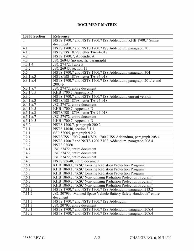
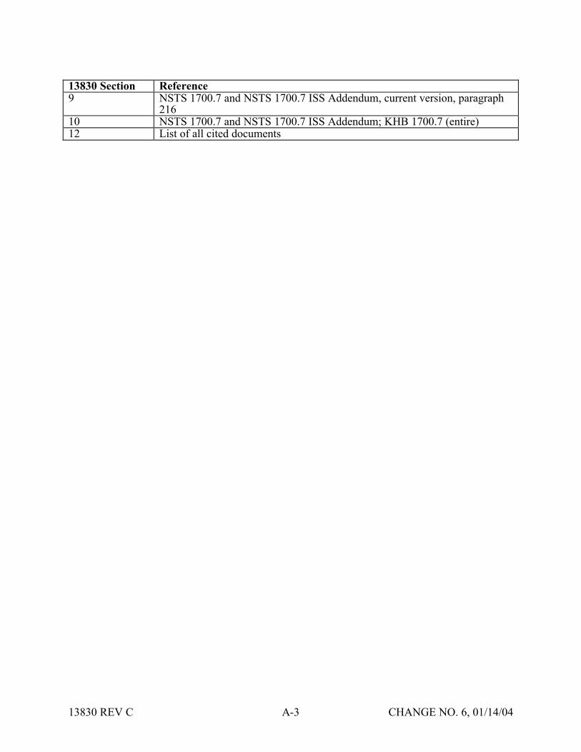
SDP Safety Data Package SMP Space Medicine ProgramSRampQA Safety Reliability and Quality Assurance SSP Space Shuttle Program
TIM Technical Interchange Meeting
VTL Verification Tracking Log
13830 REV C B-3 CHANGE NO 6 011404
PRINTING COMPLETED

PRINTING COMPLETED