Road Crossings for Water Harvesting in Seasonal Rivers...
16
Road Crossings for Water Harvesting in Seasonal Rivers: Non-Vented Drifts as Sand Dams Practical Note 31
Transcript of Road Crossings for Water Harvesting in Seasonal Rivers...

Road Crossings for Water Harvesting in Seasonal Rivers: Non-Vented Drifts as Sand Dams
Pra
ctical N
ote
31

Pra
ctic
al
No
te
#2
7
2
Pra
ctic
al
No
te #
31

Ma
nag
ing the
Micro
clima
te
1
1. Introduction
This Practical Note discusses the siting, the design and the construction of road crossings in dry riverbeds to harvest and retain flood water. With extensive road construction programs ongoing in most part of the world and 60% of new roads to be added from 2010 to 2025 globally1, the opportunities to combine road development with water management are substantial. Within this the use of road drifts – in particular the use of non-vented drifts2 functioning as sand dams in semi-arid and arid areas – is an important and in most countries underutilized opportunity to harvest flood water.
In arid and semi-arid areas, ephemeral rivers - ranging in span from 5-300 meters - dry up quickly after the rains have ceased. Typically they flow for just a few days or even a few hours each year. And even when there is not a single drop of water from the sky, the rivers can bring water from far away in one flood. Although these rivers are dry for the largest part of the year, they are the most reliable source of water for the people. The water seems to disappear, yet this is just the outside appearance. Also for these rivers applies that outside appearance is not giving you the full picture. The water is only hiding, inside the sand. Thereby having the advantages of reduced evaporation and improved purification3. The local people know the importance of their rivers, during dry times they go to the river to dig holes in the sand from where they scoop water. They use this water in their homes, for livestock and irrigation. Additionally this water recharges shallow groundwater conditions. By constructing a well upstream of the river, people can abstract water in a more convenient manner.
The importance of these rivers is evident, especially in arid and semi-arid areas where in some areas a single river flood is the only source of water for an entire year. This is qll the more reason to manage these rivers in the best fashion possible to increase their water retaining capacity.
At times these rivers also need to be crossed by
traffic. But the sandy river beds are often too loose for loaded vehicles to cross, and during floods they also cut-off road transport. Plus, the often rocky sub-surface of the river beds are too rough to drive through. The characteristics of the expansive rivers with high peak flows challenge road designers and constructors. Due to the large span size of the rivers, conventional bridges are expensive and uneconomical. At the same time traditional culvert crossings (Irish bridge) are vulnerable to being washed away by the floods due to the force of the floodwater, sedimentation and debris.
2. Non-vented drifts acting as sand dams
Non-vented drifts are a solution to this situation in providing a low cost road crossing constructed on a dry riverbed. In seasonal rivers in arid and semi-arid areas, they can act both as low volume traffic road conduits and as water retaining structures. They are important structures that will help capture
Figure 1: Example of vented bridge washed away by the force of the flood, Balochistan, Pakistan
Road Crossings for W
ater Harvesting in Seasonal Rivers
1 With even higher percentages in Sub Saharan Africa and parts of Asia for instance.
2 For ‘drifts’ different words are used as well: ‘fords’, ‘low causeways’ or ‘Irish bridges’.
3 Sand is a very suitable water filter, taking out pollutants, though it cannot guarantee drinking water quality standards.
Figure 2: Example of non-vented drift, acting as sand dam to retain the sand upstream, Makueni, Kenya.

Pra
ctic
al
No
te
#2
7
2
Reduced costs with additional benefits
As water retaining structures, non-vented drifts come at no additional cost: in fact they are even cheaper than the alternative option, i.e. vented drifts equipped with culverts. The cost of the non-vented drift is very much related to their height, which also determines their capacity to retain water. The cost of a standard non-vented drift in Kenya per meter run is approximately USD 1350. While the cost of a reinforced concrete retaining wall is USD 760 (cost estimation based on figure 2 and 4- in Makueni County, Kenya). Below Table 1 provides figures and examples of cost calculations for different types of drifts. For vented drifts there are additional costs for the pipe culverts depending on the discharge of the river. This often contributes greatly to overall costs, especially when a river has a large span size and high peak flow levels. Non-vented drifts also provide other water management related benefits. The first is the stabilization of the upstream riverbed. Provided the lay of the land allows, this will make it possible to divert water by gravity from the river bed – either perennial flows or short-term floods or spates – upstream of the drift. Where the riverbed is not stabilized and smooth, but rutted and incised, this would be difficult. Furthermore non-vented drifts cause less damage to the river bed immediately downstream of the road crossing, as water will not spout through the culverts during flood events and erode the area downstream of the drift. Water now gets the chance to cross over the entire width of the drift,
and store flood water and retain it for use during the dry seasons.
Unlike vented drifts, non-vented drifts are not equipped with culverts. This is the reason why non-vented drifts provide good opportunities to retain sand and water from ephemeral rivers, as they will act as ‘sand dams’.
Sand dams are structures that reinforce what these sandy rivers are already doing, store water inside the sand. A retaining wall across the riverbed enables the accumulation of sand upstream. Creating an increased sand storage capacity, hence increasing water retention.
Because of the absence of culverts in the drift, coarse sand and gravel will ideally be halted and accumulated in the river bed upstream of the drift. This creates a small man-made aquifer of sand and also water. Because coarse sand and gravel have large space between the pores, this can go up to 35% of total sand volume. Meaning that 35% of the volume of sand/gravel can be used to store water. A non-vented drift therefore builds upon the natural capacity of a sandy riverbed. The newly deposited material will store floodwater and makes it available for use during the dry season. The water retained in the river bed will also connect to and feed the aquifers in the banks of the river. The extent of this effect depends on local topography and geology. If there is no use of water alongside the perceived structure, landscaping along the banks can be developed with little more efforts while constructing the road crossing. This type of vegetation also helps to safeguard the structures that are put in place.
Figure 3: Showing the function of a sand dam
Pra
ctic
al
No
te #
31

Ma
nag
ing the
Micro
clima
te
3
A possible solution for making non-vented drifts passable during flood events, is to use stage construction by first constructing a non-vented drift and later on top add a vented drift, as is shown in Figure 5. This will ensure safe passage during flood seasons. However, prior analysis has to be done for different types of road volumes whether this construction is economical and necessary. As said before, flood occurrences are mostly limited to a few days a year, hence for low-volume roads a non-vented drift structure is suitable. For high-volume roads this combination of structures are essential as it makes the road passable throughout the flood duration, while at the same time retaining water.
3. Siting of a non-vented drift
There are several factors to take into account in selecting an appropriate site for a non-vented drift on a dry riverbed.
Select a narrow and shallow section of the dry river. The site of a drift should be selected in order to economise on the cost of material and labour in constructing the drift. Normally narrow sections of the river are preferred. It is also critical to do a geophysical survey at the riverbed to measure depth of sand sediments on top of a rock/sub-
reducing damage of land downstream. Hence, as river crossings, non-vented drifts are more reliable and predictable and much cheaper compared to bridges in low volume roads. During flood events however they are non-passable for the part of the duration of the flood, whereas vented drifts are passable (unless they are affected by blocked flotsam and uncontrolled flooding). The down-time on non-vented drifts can be reduced by placing pointed markers alongside the drift to guide vehicles across the drift during low floods.
Table 1: Drift construction costs, figures taken from Makueni County, Kenya
Drift construction costs per meter length in Makueni county, Kenya 2015
Kenyan Shilling per meter US dollar per meter
Drift type 1: Large drift, foundations excavated maximum depth 1.5 m and elevated 0.3 meter above the existing sandy river bed.
130,000 1240
Drift type 2: Large drift, constructed on bedrock, elevated 0.5-1.2 m above the existing river beds
80,000 760
Drift type3: Small drift, constructed on normal ordinary river channels. Little or no elevation above the existing river bed level. Depth 0.5 - 1.0 m
50,000 475
Type 4: Small drift (Road slabs), constructed on bedrock or swampy plains. Little or no elevation above the existing river bed level maximum depth 0.5m
35,000 330
Figure 4: Road crossing at Kot Kaisrani (Pakistan), the upstream riverbed is stabilized with the construction of a drift
Figure 5: Example of sandwich-drift, non-vented base + culverts + carriageway
Road Crossings for W
ater Harvesting in Seasonal Rivers
Pra
ctic
al
No
te
#2
7
4
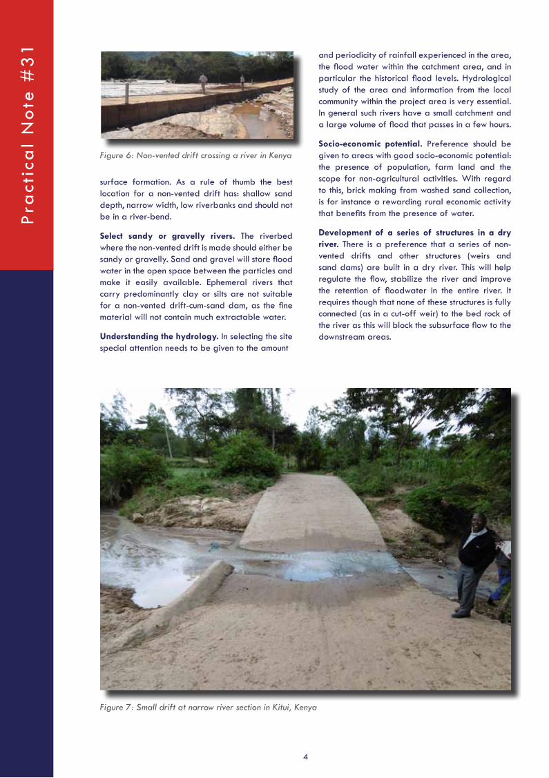
surface formation. As a rule of thumb the best location for a non-vented drift has: shallow sand depth, narrow width, low riverbanks and should not be in a river-bend.
Select sandy or gravelly rivers. The riverbed where the non-vented drift is made should either be sandy or gravelly. Sand and gravel will store flood water in the open space between the particles and make it easily available. Ephemeral rivers that carry predominantly clay or silts are not suitable for a non-vented drift-cum-sand dam, as the fine material will not contain much extractable water.
Understanding the hydrology. In selecting the site special attention needs to be given to the amount
Figure 6: Non-vented drift crossing a river in Kenya
and periodicity of rainfall experienced in the area, the flood water within the catchment area, and in particular the historical flood levels. Hydrological study of the area and information from the local community within the project area is very essential. In general such rivers have a small catchment and a large volume of flood that passes in a few hours.
Socio-economic potential. Preference should be given to areas with good socio-economic potential: the presence of population, farm land and the scope for non-agricultural activities. With regard to this, brick making from washed sand collection, is for instance a rewarding rural economic activity that benefits from the presence of water.
Development of a series of structures in a dry river. There is a preference that a series of non-vented drifts and other structures (weirs and sand dams) are built in a dry river. This will help regulate the flow, stabilize the river and improve the retention of floodwater in the entire river. It requires though that none of these structures is fully connected (as in a cut-off weir) to the bed rock of the river as this will block the subsurface flow to the downstream areas.
Figure 7: Small drift at narrow river section in Kitui, Kenya
Pra
ctic
al
No
te #
31

Ma
nag
ing the
Micro
clima
te
5
sand to the river. The coarser the sand, the more water can be stored in the pores.
With this information you can draw a longitudinal profile and plan of the river section, see Figure 8 below.
A simple and quick method to estimate the sand storage capacity of a riverbed reservoir is as follows:
Q = ( L * T * D)/6
- Q is the capacity in cubic metres
- L is the length of the dam wall in metres at full supply level
- D is the maximum depth in metres, and
- T is the throwback in metres.
This assumes that the basin is a pyramid shape whose base is the dam wall. Additionally you need to have the volume of the pores in between the sand to calculate the water storage capacity in this river section.
For example:
20*500*2/6 = 3333m3 sand capacity. In
4. Calculating storage capacity of non-vented drifts
Additionally, prior assessment needs to be done to estimate the sediment load that comes in with a flood. It has to be ensured that enough coarse sand and gravel can be accumulated, in order to prevent fine particles to be stored upstream of the retaining wall. Fine particles would diminish the full capacity of sand retaining structures. A too high wall which also traps silt and fine particles, which reduces the capacity of the structure to store water The type of catchment determines the sediment load, where rocky catchments with steep slopes bringing in more coarse material.
In order to make an estimation on how much water can be retained by a sand dam structure, the storage capacity of a sandy riverbed can be calculated. The water stored is a function of the sand stored. At first it is important to assess the potential of a sandy riverbed for retaining water prior to siting and construction. Natural indicators for high water levels are tree species, like the Acacia Robusta and green cover during dry season. Also local communities can tell you how much water they abstract from the river and for how much time, indicating the natural capacity of a river.
Furthermore a geophysical survey at site level is necessary to measure depth and width of sand sediments of the specific section (500m-1000m long upstream) of the riverbed where the drift is to be built. This can be done by probing with iron rods of 2-4m (14-16mm) into the ground. Use sub-sections of intervals of 20m. Other variables important to record are: depth to water, gradient of the riverbed, texture of sand (coarseness), floor under the sand, the height of the river banks and the vegetaion on the river banks. The catchment areas are preferrably rocky, for they transport eroded stone particles that also carry along coarse
Figure 8: Longitudinal profile of a sandy riverbed, compiled after probing survey
Figure 9: Estimating storage capacity of a reservoir
Road Crossings for W
ater Harvesting in Seasonal Rivers

Pra
ctic
al
No
te
#2
7
6
impermeable layer. However, the non-vented drift does add time and capacity of storing water in the river. Plus additional benefits, which include increased retention of water in the river banks. And also increased sand-buffer securing the drift by absorbing the water flow, thereby slowing down velocity and allowing water to infiltrate in the sand. In this way it also acts as a flood stabilizer. And, as the sand is a precious resource, if managed in a sustainable manner, sand harvesting can be an additional source of income for local communities.
5. Design and construction of non-vented drifts
A non-vented road drift consists of the following elements: the body of the drift itself, the approach road, the upstream protection of the stream and the downstream apron. The drift approaches should be extended by 10m on either side of the river banks on rivers with spans equal or greater than 50m and by 5m in rivers of spans less than 50m. The slab of the structure should be extended beyond the experienced flood level to ensure there is no damage done at the road end when the floods are high. The below figure shows a general overview of the design of a non-vented drift with design considerations.
During construction, excavation should be done to a maximum of 1.5m below the existing river bed level in sandy river beds. In rock river beds, the foundations should be laid on the rock bed.
case the volume of pores in between the sand particles is 25%, the storage capacity for water is: 0.25*3333=833 m3 meaning 833.000 liters of water.
With 15% storage capacity, this means 0.15*3333=500 m3, being 500.000 liters of water. By raising the depth D of the riverbed with a retaining wall, you can estimate the added storage of sand, hence water. Box 1 explains a calculation method which is more precise and gives the total sand storage and water yield for one year.
Specific benefits for non-vented drifts
These calculations are based on sand dams, which assumes the structure being fixed on an impermeable sub-surface. It should be noted that for non-vented drifts a sub-surface flow is allowed, because the structure is not anchored to an impermeable sub-surface underlying the sandy river. In this situation the accumulation of sediments is the same as for a sand dam/retaining wall. In order to maximize the probability to exclusively accumulate coarse-size particles, it is recommended to build the spillway in stages of 0.2-0.5m, depending on the amount and type of sediment material from the catchment.
If the non-vented drift is not fixed to the bedrock and/or impermeable layer, the volume of sand which is stored cannot store the water for a long time. The water will seep downstream through the section between the drift-base and the bedrock/
Box 1: Calculation of sand storage capacity, hence water yield of sand reservoir in river
The equation to estimate the capacity of a water reservoir:
Cp=K*D*W*T
Where CP is the reservoir capacity in (m3), K is a constant to reflect the geometrical shape of the reservoir, D and W are the depth and width of each section (m) respectively, and T is the length of the probing section (m).
Total sand storage capacityCT=∑ C1tonCT=∑ Cp1+Cp2+Cp3+ ...Cpn
Water yield of a non-vented drift YA indicates the capacity of the reservoir to yield water per year taking into account the volume of sand accumulated and the associated specific yield of the sand sediments. The formula is given by
YA=CT*n*R
Where YA is the annual water yield of the sand reservoir (m3/year) and R is a constant which reflects the number of rainy seasons.
Pra
ctic
al
No
te #
31

Ma
nag
ing the
Micro
clima
te
7
The top slab, being the top layer on which traffic passes, should have a constructed thickness of 150-200mm depending on the loading of traffic on a specific road. The drift should be filled with hard core material and compacted to a maximum depth of 1m on sandy river beds and 0.6m on rock riverbeds. A reinforcement steel of size Y12 single layer should be fixed at a spacing of 250 mm for both main bars and distribution bars. The
The foundation is the bottom part of the structure that is formed by both side walls. The foundations should have a minimum width of 500 mm and depth of construction 250 mm. Figure 10 shows the general cross-section. The walls should be constructed of 300mm thickness. The excerpts (Figure 12 taken from Figure 11) below shows the different dimensions of the foundation walls in more detail.
Figure 10: General overview of a drift crossing a sandy river bed with design considerations
Figure 11: General cross-section of a non-vented drift with design considerations
Road Crossings for W
ater Harvesting in Seasonal Rivers

Pra
ctic
al
No
te
#2
7
8
drift, gabions should be installed to avoid undermining of the foundation by the overflow of the flood water. The drift should have a curvature towards the centre of the river to ensure that the water concentrates at the middle of the river to avoid erosion of the river banks and the ends of the drift. This curvature should also be gentle enough to spread the floodwater over the width of the drift, however not extending to the river banks.
Dimensions. The dimension of the drift are given in the table to the right.
6. Preventing drift failure
The constructed drift is an investment that provides livelihood to the communities and therefore it should be prevented from any failure and wash away by flood water. Figure 16 below illustrates the preventable likely failures which should be considered during design and construction of a drift.
Body of the drift. There should be adequate support to the top slab of the drift to avoid collapse under loaded traffic and create mass resistance so as not to be washed away by the flood water. Fill
foundations, walls and the slab should be rigidly tied together to give the drift great resistance to being washed away by flood waters. The width of the road carriageway slab should vary between 3-5 m depending on the type and volume of the anticipated traffic. The height of the drift above the existing riverbed should be a maximum of 1.0 m to give enough depth for collection of sand and water upstream. However, the height of the drift should not exceed 1.0 m due to additional costs and likely chance that such a retaining wall will also accumulate finer particles, thereby deploring its water storing capacity.
At the foundation of the downstream side of the
Figure 12: Excerpt of the foundation walls and dimensions from Figure 11
Figure 13: Longitudinal profile of non-vented drift
Figure 14: Cross-section of raised non-vented drift crossing and its effect on upstream raised river bed
Drift type Excavation in river bed
Elevation above river bed
Large drift in sandy river bed
Up to1.5 meters
0.5 -1.0 meters
Large drift, constructed on bedrock
Nil 0.5-1.2 meters
Small drift, constructed on normal ordinary river channels.
0.5-1.0 meter
0.3 meter
Small drift (road slabs) - constructed on swampy plains
0.5 meter maximum
0.2 meter maximumP
ract
ica
l N
ote
#3
1

Ma
nag
ing the
Micro
clima
te
9
the banks of river with spans less than 50 meter and 10 meter for rivers with spans greater than 50 meter. Additionally, historical flood levels should be assessed together with estimations on total river discharge. The drifts should be extended at least beyond the (expected) peak flood levels.
Lowered middle section of the drift. Middle curvature should be introduced in the drift body to ensure that the flood water concentrates at the middle of the river to ensure maximum protection of the flood water from washing away the approaches of the structure. The depression in the centre of the drift may be up to 50 centimetre in a drift that is 50 meters span. In order to ensure adequate flood water spreading while preventing bank side erosion.
Anchorage to the bed rock. The drift should be firmly anchored to the bed rock of the river to the full span in rocky river beds. By doing this you ensure that no water flows under the foundation, so as to avoid undermining of the drift. The excess storm water passes over the drift. For drifts constructed in a sandy river bed underneath seepage is allowed through the sand to give infiltration water to the downstream side of the river.
Downstream gabion protection. The foundation of the structure should be protected from being undermined by the river flood flows. Gabion boxes of size 2mx1mx1m should be placed at the foot of the foundation on the downstream side of the structure to avoid undermining by the overflow of the storm water in the river. Undermining of the structure washes away the rock fill which results in collapse of the structure under traffic loading. This leads to wash away of the drift.
material of adequate strength should be placed in the structure to give the structure adequate firm resistance to not wash away by river storm water. The fill material also ensures adequate resistance to traffic loading to avoid crashing of the drift top slab. Normally rock fill is recommended with a minimum depth of 1.0 meter underneath the top slab in sand river beds and 0.6m in drifts constructed on rock river beds – see Figure 15.
Robustness. Care should be taken to ensure that the foundations, walls and top slab are rigidly tied together by reinforcement steel to ensure firmness of the structure so that flood water does not penetrate into the structure and carry the structure away. The reinforcement steel should be high tensile steel. The materials for making concrete should meet all requirements as per the recommended standard specifications for road and bridge construction. The structure should be extended and anchored adequately beyond the river banks to avoid flood water going over the edges of the structure and undermining the drift ends. This could cause approach failure which cuts off the road from the drift, especially if a drift links directly to an unpaved road this can trigger erosion. As a rule, the drifts should be extended by 5 meter beyond
Figure 15: Overview of non-vented drift with preventable failure features
Figure 16: Example of a retaining wall, holding sand upstream
Road Crossings for W
ater Harvesting in Seasonal Rivers

Pra
ctic
al
No
te
#2
7
10
concrete or gabions. Generally, the gabion walls are recommended to be constructed at the upper parts of the river course and the concrete walls at the lower parts of the river as the concrete walls are stronger to resist high forces of the flood water.
Gabion boxes are generally used to protect the foundation of the retaining wall from under scouring in places where the wall is constructed in sand or natural soil. This is similar to its usage for non-vented drifts. Therefore gabions can be attached to the foundation of the retaining wall through hook bars, but this is not always necessary, the gabion structure can also stay in place by gravitational weight. The gabions are anchored into the river bank, they are placed 2m inside the edge of the river bank in order to resist flood water force by their gravitational weight, just like the drifts.
Gabions use stones which are cheap and locally
7. Retaining walls
Additional retaining walls can be constructed on the upstream and downstream sides of the drift to give increased effects of collection of sand and water in the river. Through cascading these structures the accumulation of sand can be optimized. Furthermore retaining walls check the flood flow, hence they protect the drift from strong forces of the flood water. And they function in such a way to retain more water to make the river a green belt, serving people both upstream and downstream.
Retaining walls should be elevated up to 1m above the existing river bed level, sub-surface dams can also be used. Retaining walls should be excavated to a depth of 1.5m below the river bed level to ensure adequate strength. A retaining wall basically works exactly the same as a sand dam. The walls can be constructed either as reinforced
Figure 17: General design of a retaining wall
Figure 18: Retaining wall construction works - longitudinal profile
Pra
ctic
al
No
te #
31

Ma
nag
ing the
Micro
clima
te
11
upper parts of the river course to act as erosion protection works and also as water retaining structures.
The elevation of the drift and the walls above the river bed determines the additional material deposited and the amount of water retained. The course material is deposited at the river bed while the finer material is washed off the drift and walls to downstream of the river. The deposition is scheduled over a number of years until the drift and walls are filled. Later additional height can be
available. Making them a suitable solution to re-inforce river crossing structures. In upper parts of the river catchment, gabions can serve as retaining walls by themselves. However, at the lower part of the river concrete retaining walls are used because they are stronger so they can resist more force.
The figure below shows the general arrangement for design of a retaining wall.
Gabion mesh of boxes measuring 2.0mx1.0m x 1.0m depth are also used as retaining walls in the
Figure 19: Design of gabions for a retaining wall structure in a river bed
Figure 20: Side view of the river showing the gabion design construction
Road Crossings for W
ater Harvesting in Seasonal Rivers
Pra
ctic
al
No
te
#2
7
12
should be class 15/20 (1:3:6) ratios of Cement, Fine aggregates and Course aggregates respectively and as detailed in the drawings supplied by the design Engineer. The concrete should be well mixed by concrete mixer and compacted in place using a poker vibrator.
Water/cement ratio should be well controlled. Usually a minimum water content of half the cement content in the total mix should be used. This ensures that the cement is not washed away during the vibration of the concrete resulting in high strength of the structure.
Concrete design mix should be prepared by the design engineer and tested to meet the required strength before application in the works.
Well compacted rock fill should be placed to a minimum depth of 1.0 metres to give the drift enough mass.
The concrete structures are constructed using form work. All form work to be applied should be of good finish and ensured that it is firm before placing in the concrete to ensure good workmanship.
added to increase further storage and adjustment of the river levels. It is of key importance to ensure that only the coarse material is accumulated for that material has the greatest capacity for water storage. Therefore the drift height should not be too high at first construction and it is recommended to raise this height in stages, after each flood event until the preferred height is established.
8. Construction materials
All materials to be used for the construction of the drifts and water retaining structures should be tested to ensure they meet the standard specifications for Roads and bridge construction for the specific country.
Drifts should be constructed of reinforced concrete with twisted steel bars of size Y12 single layer spaced at 250mm centre to centre.
Concrete class to be used should 25/20 (1:1½:3) for structural concrete and for blinding concrete
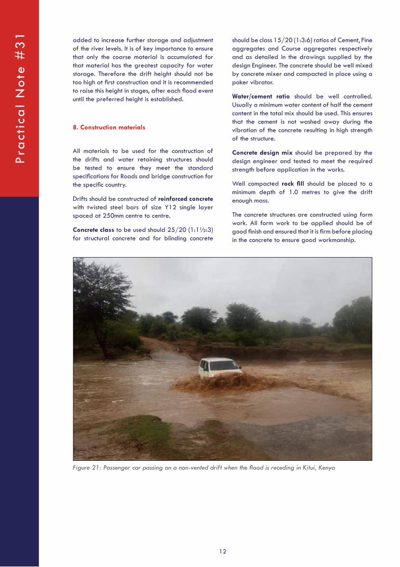
Figure 21: Passenger car passing on a non-vented drift when the flood is receding in Kitui, Kenya
Pra
ctic
al
No
te #
31

Ma
nag
ing the
Micro
clima
te
13
Road Crossings for W
ater Harvesting in Seasonal Rivers

Colophon
This Practical Note has been prepared by Engineer Benson Masila, based on the extensive work on non-vented drifts in Kenya. Contributions were made by Frank van Steenbergen, Allah Bakhsh and Luwieke Bosma. The note was finalized with support of the Roads for Water Alliance and the IFAD-EU supported program “Africa To Asia And Back: Testing Adaptation In Flood-Based Farming Systems”.
For more information: www.spate-irrigation.org.
September 2017
Pra
ctic
al
No
te
#2
7P
ract
ica
l N
ote
#3
1