RMU HV Switchgear
28
UNDERGROUND CONSTRUCTION MANUAL HV SWITCHGEAR Go to SECTION INDEX Back to MAIN INDEX
description
RING MAIN UNIT
Transcript of RMU HV Switchgear

UNDERGROUND CONSTRUCTION MANUAL
HV SWITCHGEAR Go to SECTION INDEX Back to MAIN INDEX
DESCRIPTION DWG
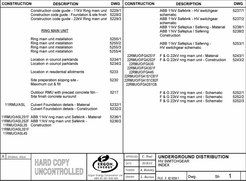
INDEX
�
�
�
�
�
31/5/11
62 5254 11���
���
��
�
�
�
�
�
�
�
�
�
�
5229/1
5229/3
CONSTRUCTION CONSTRUCTION DESCRIPTION DWG
5234/1
5229/2
HARD COPYUNCONTROLLED
HV SWITCHGEAR
C. Noel
A. Bletchly
L. Burton
Construction code guide - Foundation & site finish
Construction code guide - 22kV Ring main unit
Construction code guide - 11kV Ring main unit
Location in council parklands
Location in council parklands 5234/2
Location in residential allotments 5233
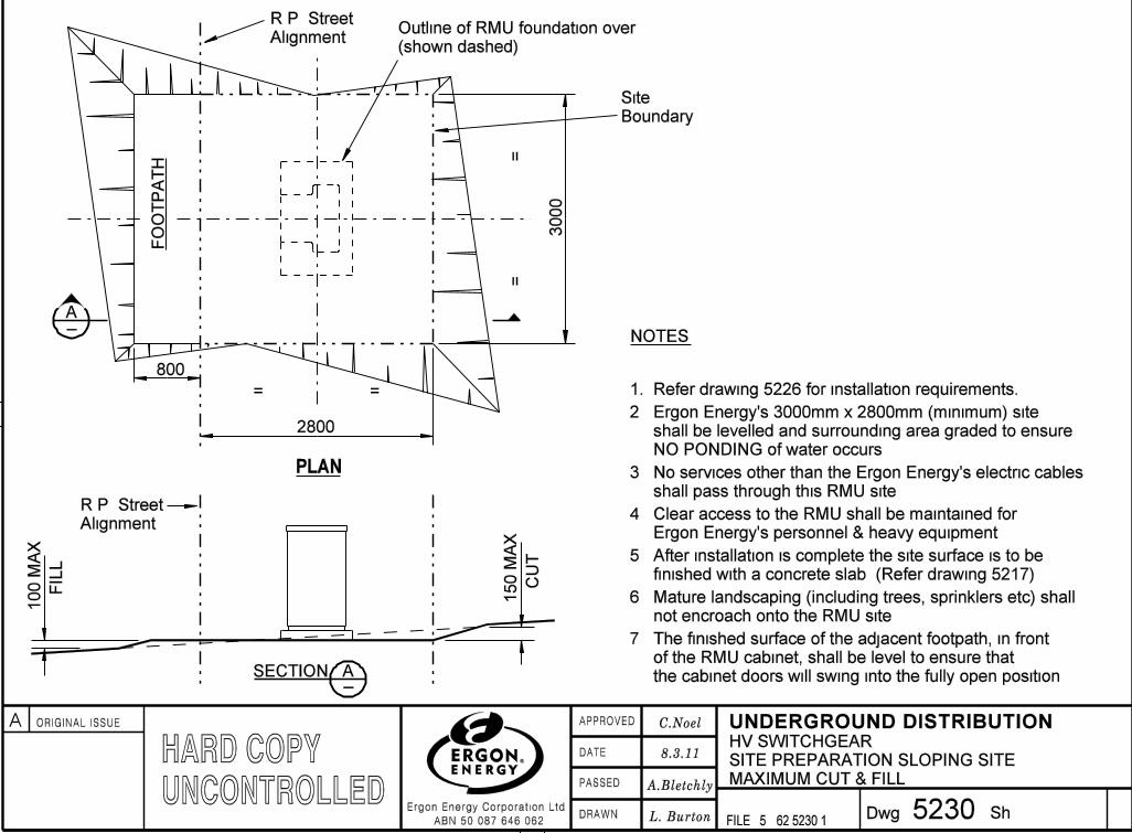
5230
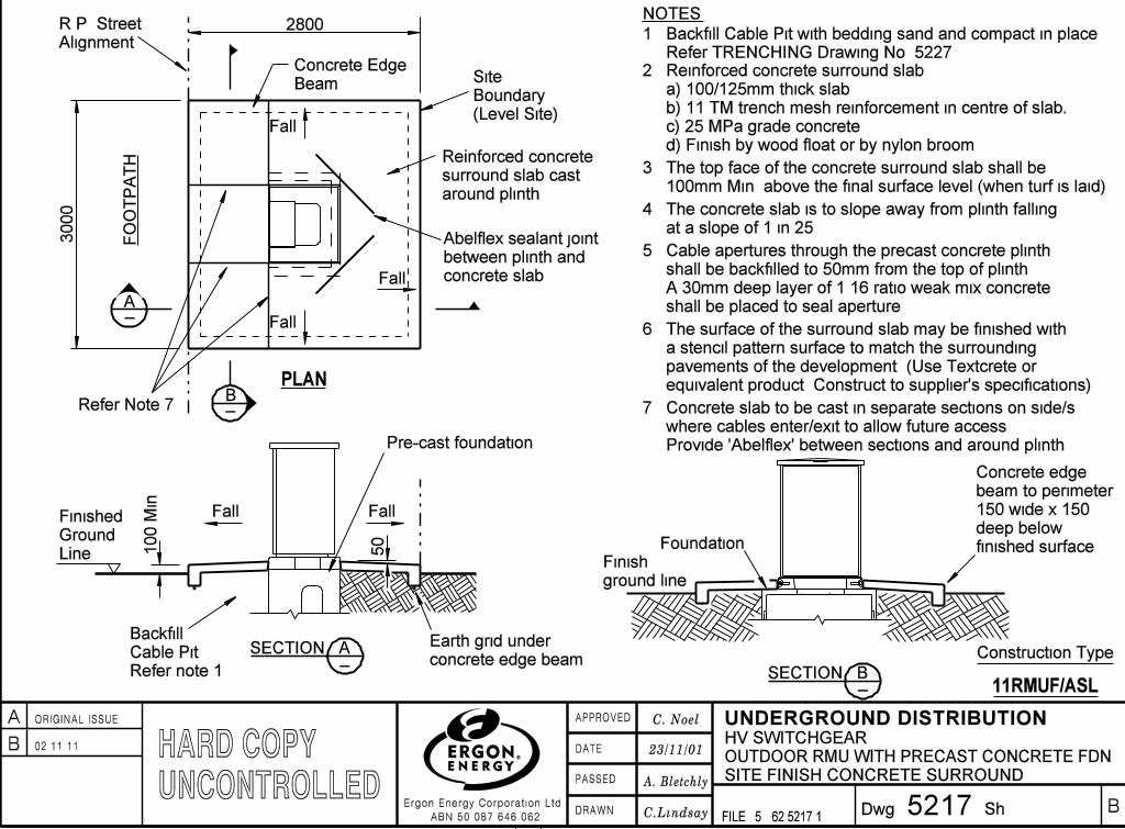
Outdoor RMU with precast concrete fdn -
Site finish concrete suround
5217
RING MAIN UNIT
5232/1
5232/2
Culvert Foundation details - Material
Culvert Foundation details - Construction
11RMU/ASL
5236/1
5236/2
ABB 11kV ring main unit Safelink - Material11RMU/O/ASL2S1F
11RMU/O/ASL2S2F
11RMU/O/ASL3S1F
11RMU/O/ASL3S
11RMU/O/ASL4S
ABB 11kV ring main unit Safelink -
Construction
Site preperation sloping site -
Maximum cut & fill
5237/1
5237/2
5238/1
5238/2
5253/1ABB 11kV Safeplus / Safering -
HV switchgear schematic
ABB 11kV Safeplus / Safering - Material
5243/1
5243/2
22RMU/O/FGA2S1F F & G 22kV ring main unit - Material
F & G 22kV ring main unit - Construction22RMU/O/FGA2S2F
22RMU/O/FGA3S1F
22RMU/O/FGA2S1CB
22RMU/O/FGA3S
22RMU/O/FGA4S
22RMU/O/FGA1S1CB1F
22RMU/O/FGA1S1CB2F
5252/1
5252/2
F & G 22kV ring main unit - Schematic
F & G 22kV ring main unit - Schematic
5252/3F & G 22kV ring main unit - Schematic
ABB 11kV Safelink - HV switchgear
schematic
ABB 11kV Safelink - HV switchgear
schematic
ABB 11kV Safeplus / Safering
Construction5255/1Ring main unit installation
5255/2Ring main unit installation
5255/3Ring main unit installation
5255/4Ring main unit installation
�
�
�
�
�
�
�
�
�
�
�
�
A ORIGINAL ISSUE
�
�
�
�
�
�
��
�
�
�
�
�
��
�
����� �
��
�
�
�
�
��
�
�
�
�
���
�
�
�
�
�
�
�
�
�
�
�
�
�
�
�
�
�
�
�
�
�
�
�
�
�
�
�
�
�
������
�
��
�
�
�DRAWN
DATE
PASSED
APPROVED
Ergon Energy Corporation Ltd
ABN 50 087 646 062Dwg Sh
FILE: 5
UNDERGROUND DISTRIBUTION
5217
�
�
�
�
�
�
�
� �
�
�
�
�
�
��
�
�
� C.Lindsay
23/11/01
62 5217 1
SITE FINISH CONCRETE SURROUND
OUTDOOR RMU WITH PRECAST CONCRETE FDN
F
30
00
F
F 2800F
Concrete Edge
Beam
F
Fall
F
F
F
Fall
Fall
F
F
surround slab cast
F
Site
Boundary
(Level Site)
A_
PLAN
FO
OT
PA
TH
Alignment
R.P. Street
F
Reinforced concrete
around plinth
between plinth and
Abelflex sealant joint
concrete slab
NOTES:
2. Reinforced concrete surround slab:
a) 100/125mm thick slab:
b) 11 TM trench mesh reinforcement in centre of slab:
c) 25 MPa grade concrete:
d) Finish by wood float or by nylon broom.
4. The concrete slab is to slope away from plinth falling
at a slope of 1 in 25.
5. Cable apertures through the precast concrete plinth
shall be backfilled to 50mm from the top of plinth.
A 30mm deep layer of 1:16 ratio weak mix concrete
shall be placed to seal aperture.
6. The surface of the surround slab may be finished with
a stencil pattern surface to match the surrounding
pavements of the development. (Use Textcrete or
equivalent product. Construct to supplier’s specifications).
3. The top face of the concrete surround slab shall be
100mm Min. above the final surface level (when turf is laid).
Line
Ground
Finished
_SECTION A
Backfill
Cable Pit
Refer note 1.
F
Earth grid under
concrete edge beam
Fall
F
F
Fall
50 F
F
F
F10
0 M
in.
F
F
HV SWITCHGEAR
_SECTION B
Concrete edge
beam to perimeter
150 wide x 150
deep below
finished surface.Foundation
Finish
ground line
_B
F
C. Noel
A. Bletchly
F
Construction Type
11RMUF/ASL
Pre-cast foundation
1. Backfill Cable Pit with bedding sand and compact in place.
Refer TRENCHING Drawing No. 5227.
B 02.11.11
B
Refer Note 7
FF
F
7. Concrete slab to be cast in separate sections on side/s
where cables enter/exit to allow future access.
Provide ’Abelflex’ between sections and around plinth.
HARD COPYUNCONTROLLED
�
�
�
�
�
�
�
�
�
�
�
�
A ORIGINAL ISSUE
�
�
�
�
�
�
��
�
�
�
�
�
��
�
����� �
��
�
�
�
�
��
�
�
�
�
���
�
�
�
�
�
�
�
�
�
�
�
�
�
�
�
�
�
�
�
�
�
�
�
�
�
�
�
�
�
������
�
��
�
�
�DRAWN
DATE
PASSED
APPROVED
Ergon Energy Corporation Ltd
ABN 50 087 646 062Dwg Sh
FILE: 5
UNDERGROUND DISTRIBUTION

EXAMPLE:-
CONSTRUCTIONSVOLTAGE
CONSTRUCTION CODE GUIDE
Code shown within dashed box
appears on relevant construction
detail drawings in this manual.A
522962 5229 1
T.Borg
11kV RING MAIN UNIT CONSTRUCTION CODE
11 RMU/O/ASL 2S1F
11 = 11kV RMU = Ring Main Unit
LOCATION
O = Outdoor
HV SWITCHGEAR
ASL = ABB SafeLink
ASP = ABB SafePlus
ASR = ABB SafeRing
CONFIGURATION
2S1F = 2 switch + 1 fuse
2S2F = 2 switch + 2 fuse
3S = 3 switch
4S = 4 switch
3S1F = 3 switch + 1 fuse
1S1CB1F = 1 switch + 1 circuit breaker + 1 fuse
1S1CB2F = 1 switch + 1 circuit breaker + 2 fuse
2S1CB = 2 switch + 1 circuit breaker
11RMU/O/ASL2S1F = 11kV, Ring Main Unit, outdoor, ABB SafeLink, 2 switches + 1 fuse.
C. Noel
A. Bletchly
1
11kV RING MAIN UNIT
9/9/10HV SWITCHGEARHARD COPY
UNCONTROLLED�
�
�
���
�
�
�
�
�
�
�
�
�
�
�
�
�
A ORIGINAL ISSUE
�
�
�
���
�
�
�
�
�
�
��
�
�
�
�
�
��
�
����� �
��
�
�
�
�
��
�
�
�
�
���
�
�
�
�
�
�
�
�
�
�
�
�
�
�
�
�
�
�
�
�
�
�
�
�
�
�
�
�
�
������
�
��
�
�
�DRAWN
DATE
PASSED
APPROVED
Ergon Energy Corporation Ltd
ABN 50 087 646 062Dwg Sh
FILE: 5
UNDERGROUND DISTRIBUTION
CONSTRUCTION CODE GUIDE
5229 262 5229 2
C. Noel
A. Bletchly�
�
�
�
�
�
�
�
�
�
��
��
�
�
EXAMPLE:-
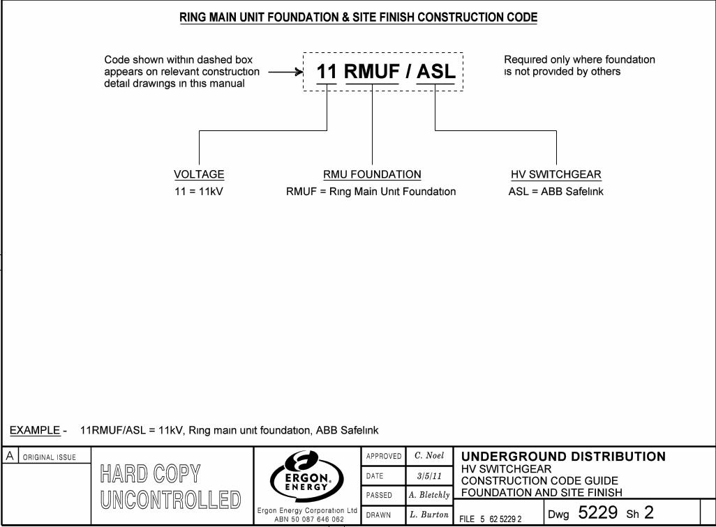
Required only where foundation
is not provided by others.
Code shown within dashed box
appears on relevant construction
detail drawings in this manual.A
FOUNDATION AND SITE FINISH
3/5/11
RING MAIN UNIT FOUNDATION & SITE FINISH CONSTRUCTION CODE
11 RMUF / ASL
11 = 11kV
VOLTAGE RMU FOUNDATION
RMUF = Ring Main Unit Foundation
HV SWITCHGEAR
ASL = ABB Safelink
11RMUF/ASL = 11kV, Ring main unit foundation, ABB Safelink
L. Burton
HV SWITCHGEARHARD COPYUNCONTROLLED
�
�
�
�
�
�
�
�
�
�
�
�
A ORIGINAL ISSUE
�
�
�
�
�
�
��
�
�
�
�
�
��
�
����� �
��
�
�
�
�
��
�
�
�
�
���
�
�
�
�
�
�
�
�
�
�
�
�
�
�
�
�
�
�
�
�
�
�
�
�
�
�
�
�
�
������
�
��
�
�
�DRAWN
DATE
PASSED
APPROVED
Ergon Energy Corporation Ltd
ABN 50 087 646 062Dwg Sh
FILE: 5
UNDERGROUND DISTRIBUTION

EXAMPLE:-
CONSTRUCTIONSVOLTAGE
CONSTRUCTION CODE GUIDE
Code shown within dashed box
appears on relevant construction
detail drawings in this manual.A
5229 362 5229 3
T.Borg
22kV RING MAIN UNIT CONSTRUCTION CODE
22 RMU/O/FGA 3S1F
22 = 22kV RMU = Ring Main Unit
LOCATION
O = Outdoor
HV SWITCHGEAR CONFIGURATION
2S1F = 2 switch + 1 fuse
FGA = Felton & Guillaume (F&G) 1S1CB1F = 1 switch + 1 circuit breaker + 1 fuse
1S1CB2F = 1 switch + 1 circuit breaker + 2 fuse
2S1CB = 2 switch + 1 circuit breaker
2S2F = 2 switch + 2 fuse
3S = 3 switch
3S1F = 3 switch + 1 fuse
4S = 4 switch
22RMU/O/FGA3S1F = 22kV, Ring Main Unit, outdoor, Felton and Guillaume (F&G), 3 switches + 1 fuse.
C. Noel
A. Bletchly�
�
�
�
�
�
�
�
�
�
��
��
�
�
22kV RING MAIN UNIT
9/9/10HV SWITCHGEARHARD COPY
UNCONTROLLED�
�
�
���
�
�
�
�
�
�
�
�
�
�
�
�
�
A ORIGINAL ISSUE
�
�
�
���
�
�
�
�
�
�
��
�
�
�
�
�
��
�
����� �
��
�
�
�
�
��
�
�
�
�
���
�
�
�
�
�
�
�
�
�
�
�
�
�
�
�
�
�
�
�
�
�
�
�
�
�
�
�
�
�
������
�
��
�
�
�DRAWN
DATE
PASSED
APPROVED
Ergon Energy Corporation Ltd
ABN 50 087 646 062Dwg Sh
FILE: 5
UNDERGROUND DISTRIBUTION
FO
OT
PA
TH
NOTES:
�
�
�
�
�
�
�
�
�
�
�
�
�
�
�
�
�
�
�
�
�
�
�
�
�
�
�
�
�
�
�
�
�
�
�
������
��
PLAN
L. Burton
MAXIMUM CUT & FILL
(shown dashed)
30
00
800
A_
FIL
L
100 M
AX
R.P. Street
Alignment
_
150 M
AX
CU
T
2800
SECTION A
2. Ergon Energy’s 3000mm x 2800mm (minimum) site
shall be levelled and surrounding area graded to ensure
NO PONDING of water occurs.
523062 5230 1
8.3.11SITE PREPARATION SLOPING SITE
Outline of RMU foundation over
1. Refer drawing 5226 for installation requirements.
3. No services other than the Ergon Energy’s electric cables
shall pass through this RMU site.
4. Clear access to the RMU shall be maintained for
Ergon Energy’s personnel & heavy equipment.
6. Mature landscaping (including trees, sprinklers etc) shall
not encroach onto the RMU site.
7. The finished surface of the adjacent footpath, in front
of the RMU cabinet, shall be level to ensure that
the cabinet doors will swing into the fully open position.
FF
F
F
F
F
F
F
F
F
F
FF
R.P. Street
Alignment
= =
==
Site
Boundary
F
5. After installation is complete the site surface is to be
finished with a concrete slab. (Refer drawing 5217).
HV SWITCHGEAR
A.Bletchly
C.Noel
HARD COPYUNCONTROLLED
�
�
�
�
�
�
�
�
�
�
�
�
A ORIGINAL ISSUE
�
�
�
�
�
�
��
�
�
�
�
�
��
�
����� �
��
�
�
�
�
��
�
�
�
�
���
�
�
�
�
�
�
�
�
�
�
�
�
�
�
�
�
�
�
�
�
�
�
�
�
�
�
�
�
�
������
�
��
�
�
�DRAWN
DATE
PASSED
APPROVED
Ergon Energy Corporation Ltd
ABN 50 087 646 062Dwg Sh
FILE: 5
UNDERGROUND DISTRIBUTION
NOTES:
���������� �
��B� 1/2 �DISC
���� �
�
�
�
�
�
�
�
�
�
�
�
�
�
�
� L. Burton
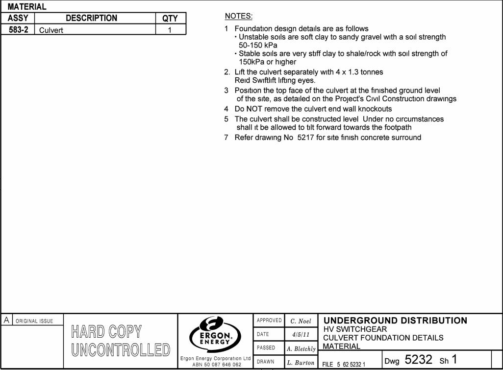
1. Foundation design details are as follows:1
ASSY QTYDESCRIPTION
MATERIAL
1523262 5232 1
583-2 CulvertUnstable soils are soft clay to sandy gravel with a soil strength
50-150 kPa.
Stable soils are very stiff clay to shale/rock with soil strength of
150kPa or higher.
2. Lift the culvert separately with 4 x 1.3 tonnes
Reid Swiftlift lifting eyes.
3. Position the top face of the culvert at the finished ground level
of the site, as detailed on the Project’s Civil Construction drawings.
4. Do NOT remove the culvert end wall knockouts.
5. The culvert shall be constructed level. Under no circumstances
shall it be allowed to tilt forward towards the footpath.
7. Refer drawing No. 5217 for site finish concrete surround.
CULVERT FOUNDATION DETAILS
A. Bletchly
C. Noel
4/5/11
MATERIAL
HV SWITCHGEARHARD COPYUNCONTROLLED�
�
�
���
�
�
�
�
�
�
�
�
�
�
�
�
�
A ORIGINAL ISSUE
�
�
�
���
�
�
�
�
�
�
��
�
�
�
�
�
��
�
����� �
��
�
�
�
�
��
�
�
�
�
���
�
�
�
�
�
�
�
�
�
�
�
�
�
�
�
�
�
�
�
�
�
�
�
�
�
�
�
�
�
������
�
��
�
�
�DRAWN
DATE
PASSED
APPROVED
Ergon Energy Corporation Ltd
ABN 50 087 646 062Dwg Sh
FILE: 5
UNDERGROUND DISTRIBUTION

�
�
�
�
�
�
�
�
�
�
�
�
�
�
�
�
�
�
�
�
�
�
�
�
�
�
�
�
�
�
�
�
�
�
�
������
�� L. Burton 523262 5232 1
8.3.11
C. Noel
A. Bletchly
F
_SECTION A
B_
=
=
A_
3000 S
ite
Compact pit sand
SECTION B_PLAN
Backfill with approved
suitable material and
compact in place
R.P. Street
Alignment
2800 SiteF
F
FF
FFF
F
Site
Boundary
F
Finished Ground
Line (Site)
Cable
entry
Assy 583-2
Footpath
F
Precast concrete
plinth supplied
with RMU
F
F
HV cables
F
F
F
F
F
Stable
Un-stable100
50
F
F
1180 S
table
12
80
Un
sta
ble
2
Construction Type
11RMU/ASL
F
F
F
F= =
CULVERT FOUNDATION DETAILS
CONSTRUCTION
HV SWITCHGEARHARD COPYUNCONTROLLED
�
�
�
�
�
�
�
�
�
�
�
�
A ORIGINAL ISSUE
�
�
�
�
�
�
��
�
�
�
�
�
��
�
����� �
��
�
�
�
�
��
�
�
�
�
���
�
�
�
�
�
�
�
�
�
�
�
�
�
�
�
�
�
�
�
�
�
�
�
�
�
�
�
�
�
������
�
��
�
�
�DRAWN
DATE
PASSED
APPROVED
Ergon Energy Corporation Ltd
ABN 50 087 646 062Dwg Sh
FILE: 5
UNDERGROUND DISTRIBUTION
�
�
�
�
�
�
�
�
�
�
�
�
�
�
�
�
�
�
�
�
�
�
�
�
�
�
�
�
�
�
�
�
�
�
�
������
�� L. Burton 523362 5233 1
8/3/11
C. Noel
A. Bletchly
F
F
FO
OT
PA
TH
R.P. Street
Alignment
F
6000
F
F
30
00
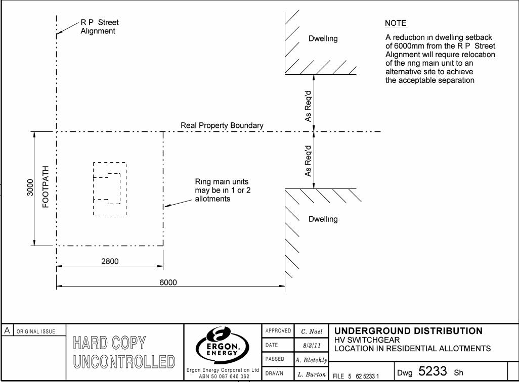
NOTE:
Real Property Boundary
F
F2800
Dwelling
Dwelling
As
Req’d
As
Req’d
FF
FF
Ring main units
may be in 1 or 2
allotments
F
A reduction in dwelling setback
of 6000mm from the R.P. Street
Alignment will require relocation
of the ring main unit to an
alternative site to achieve
the acceptable separation.
LOCATION IN RESIDENTIAL ALLOTMENTS
HV SWITCHGEARHARD COPYUNCONTROLLED
�
�
�
�
�
�
�
�
�
�
�
�
A ORIGINAL ISSUE
�
�
�
�
�
�
��
�
�
�
�
�
��
�
����� �
��
�
�
�
�
��
�
�
�
�
���
�
�
�
�
�
�
�
�
�
�
�
�
�
�
�
�
�
�
�
�
�
�
�
�
�
�
�
�
�
������
�
��
�
�
�DRAWN
DATE
PASSED
APPROVED
Ergon Energy Corporation Ltd
ABN 50 087 646 062Dwg Sh
FILE: 5
UNDERGROUND DISTRIBUTION
�
�
�
�
�
�
�
�
�
�
�
�
�
�
�
�
�
�
�
�
�
�
�
������
�� L. Burton 523462 5234 1
C. Noel
A. Bletchly
10.3.11
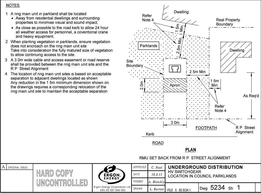
NOTES:
Parklands
1.
2.
3.
2.5m Min.
2.5
m M
in.
4.
Apron
PLAN
Dwelling
Real Property
Boundary
1.5m
Min.
R.P. Street
Alignment
FOOTPATH
Kerb
ROAD2.0
m
F
F
F
F
F
F
F
F
F
F
F
F
F
F
Dwelling
1.5
m
Min
.
F
F
Site
Boundary
As Req’d
3.0m
Away from residential dwellings and surrounding
properties to minimise visual and sound impact;
As close as possible to the road kerb to allow 24 hour
all weather access for personnel, a coventional crane
and heavy equipment.
Refer
Note 4
Refer
Note 4
F
F
F
F
RMU SET BACK FROM R.P. STREET ALIGNMENT
When planting vegetation in parklands, ensure vegetation
does not encroach on the ring main unit site.
Take into consideration the fully matured size of vegetation
to allow continuing access to the site.
A ring main unit in parkland shall be located:
The location of ring main unit sites is based on acceptable
separation to adjacent dwellings located as shown.
Any reduction in the 1.5m minimum dimension shown on
the drawings requires a corresponding relocation of the
ring main unit site to maintain the acceptable separation.
LOCATION IN COUNCIL PARKLANDS
A 3.0m wide cable and access easement or road reserve
shall be provided between the ring main unit site and the
R.P. Street Alignment.
1
HV SWITCHGEARHARD COPYUNCONTROLLED�
�
�
���
�
�
�
�
�
�
�
�
�
�
�
�
�
A ORIGINAL ISSUE
�
�
�
���
�
�
�
�
�
�
��
�
�
�
�
�
��
�
����� �
��
�
�
�
�
��
�
�
�
�
���
�
�
�
�
�
�
�
�
�
�
�
�
�
�
�
�
�
�
�
�
�
�
�
�
�
�
�
�
�
������
�
��
�
�
�DRAWN
DATE
PASSED
APPROVED
Ergon Energy Corporation Ltd
ABN 50 087 646 062Dwg Sh
FILE: 5
UNDERGROUND DISTRIBUTION

�
�
�
�
�
�
�
�
�
�
�
�
�
�
�
�
�
�
�
�
�
�
�
������
�� L. Burton 523462 5234 2
C. Noel
A. Bletchly
10.3.11
FOOTPATH
ROAD
Parklands
Kerb
PLAN
Dwelling
R.P. Street
Alignment
6.0m Min.
F
Site
Boundary
F
F
F
F
F
As Req’d
Real Property Boundary
FOOTPATH
ROAD
Parklands
Kerb
PLAN
Dwelling
F
Site
BoundaryF
F
F
F
F
Real Property Boundary
Less than
6.0m2.5m Min.
F
F
1.5m
Min.
F
F
Refer Note 4
Sheet 1.
R.P. Street
Alignment
RMU ADJOINING R.P. STREET ALIGNMENT
LOCATION IN COUNCIL PARKLANDS
2
HV SWITCHGEARHARD COPYUNCONTROLLED
�
�
�
�
�
�
�
�
�
�
�
�
A ORIGINAL ISSUE
�
�
�
�
�
�
��
�
�
�
�
�
��
�
����� �
��
�
�
�
�
��
�
�
�
�
���
�
�
�
�
�
�
�
�
�
�
�
�
�
�
�
�
�
�
�
�
�
�
�
�
�
�
�
�
�
������
�
��
�
�
�DRAWN
DATE
PASSED
APPROVED
Ergon Energy Corporation Ltd
ABN 50 087 646 062Dwg Sh
FILE: 5
UNDERGROUND DISTRIBUTION
���������� �����
�
�
�
L. Burton
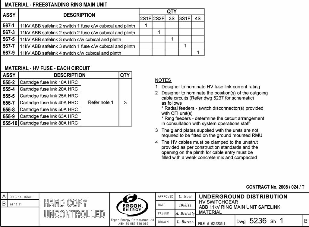
ASSY DESCRIPTIONQTY
NOTES:
10/3/11
567-9
62 5236 15236
C. Noel
A. Bletchly
567-1
567-5
567-3
567-7
555-4
555-5
555-7
555-8
555-9
555-10
11kV ABB safelink 2 switch 1 fuse c/w cubical and plinth
11kV ABB safelink 2 switch 2 fuse c/w cubical and plinth
11kV ABB safelink 3 switch 1 fuse c/w cubical and plinth
11kV ABB safelink 3 switch c/w cubical and plinth
11kV ABB safelink 4 switch c/w cubical and plinth
1
2S1F 2S2F 3S1F3S 4S
1.
2.
The gland plates supplied with the units are not
required to be fitted on the ground mounted RMU
3.
The HV cables must be clamped to the unistrut
provided as per construction standards and the
opening on the plinth for cable entry must be
filled with a weak concrete mix and compacted
MATERIAL - FREESTANDING RING MAIN UNIT
ASSY DESCRIPTION QTY
3
1
1
1
1
1
MATERIAL
MATERIAL - HV FUSE - EACH CIRCUIT
Refer note 1
555-2 Cartridge fuse link 10A HRC
Cartridge fuse link 20A HRC
Cartridge fuse link 25A HRC
Cartridge fuse link 40A HRC
Cartridge fuse link 50A HRC
Cartridge fuse link 63A HRC
Cartridge fuse link 80A HRC
Designer to nominate HV fuse link current rating
CONTRACT No. 2008 / 024 / T
ABB 11kV RING MAIN UNIT SAFELINK
HV SWITCHGEARB 24.11.11
�
B
4.
Designer to nominate the position(s) of the outgoing
cable circuits (Refer dwg 5237 for schematic)
as follows:
* Radial feeders - switch disconnector(s) provided
with CFI unit(s)
* Ring feeders - determine the circuit arrangement
in consultation with system operations staff.
HARD COPYUNCONTROLLED
�
�
�
���
�
�
�
�
�
�
�
�
�
�
�
�
�
A ORIGINAL ISSUE
�
�
�
���
�
�
�
�
�
�
��
�
�
�
�
�
��
�
����� �
��
�
�
�
�
��
�
�
�
�
���
�
�
�
�
�
�
�
�
�
�
�
�
�
�
�
�
�
�
�
�
�
�
�
�
�
�
�
�
�
������
�
��
�
�
�DRAWN
DATE
PASSED
APPROVED
Ergon Energy Corporation Ltd
ABN 50 087 646 062Dwg Sh
FILE: 5
UNDERGROUND DISTRIBUTION
���������� �����
�
�
�
L. Burton
10/3/11HARD COPYUNCONTROLLED
62 5236 25236
C. Noel
A. Bletchly
CONTRACT No. 2008 / 024 / T
2
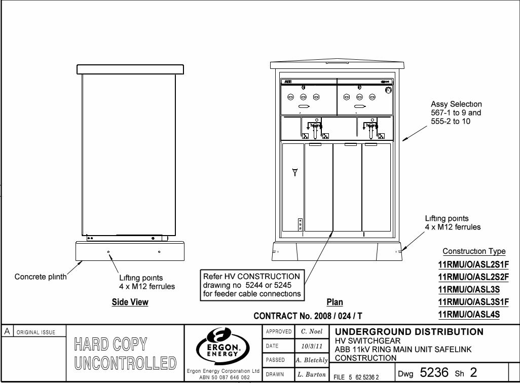
Construction Type
11RMU/O/ASL2S1F
11RMU/O/ASL2S2F
11RMU/O/ASL3S
11RMU/O/ASL3S1F
11RMU/O/ASL4S
Assy Selection
567-1 to 9 and
555-2 to 10
F
F
F
Concrete plinth
F
Refer HV CONSTRUCTION
drawing no. 5244 or 5245
for feeder cable connections
Side View Plan
F
Lifting points
4 x M12 ferrules
Lifting points
4 x M12 ferrules
CONSTRUCTION
ABB 11kV RING MAIN UNIT SAFELINK
HV SWITCHGEAR�
�
�
�
�
�
�
�
�
�
�
�
A ORIGINAL ISSUE
�
�
�
�
�
�
��
�
�
�
�
�
��
�
����� �
��
�
�
�
�
��
�
�
�
�
���
�
�
�
�
�
�
�
�
�
�
�
�
�
�
�
�
�
�
�
�
�
�
�
�
�
�
�
�
�
������
�
��
�
�
�DRAWN
DATE
PASSED
APPROVED
Ergon Energy Corporation Ltd
ABN 50 087 646 062Dwg Sh
FILE: 5
UNDERGROUND DISTRIBUTION

���������� �����
�
�
�
L. Burton
10/3/11HARD COPYUNCONTROLLED
62 5237 15237
C. Noel
A. Bletchly
FEEDER
CABLE
FEEDER
CABLE
FEEDER
CABLE
F
2S1F 11kV ABB safelink RMU 2 switch 1 fuse
F
Note:
(CFI) on this switch disconnector unit
Represents circuit fault indicator
FEEDER
CABLE
FEEDER
CABLE
FEEDER
CABLE
F
2S2F 11kV ABB safelink RMU 2 switch 2 fuse
F
Note:
(CFI) on this switch disconnector unit
Represents circuit fault indicator
FEEDER
CABLE
FEEDER
CABLE
FEEDER
CABLE
FEEDER
CABLE
F
3S1F 11kV ABB safelink RMU 3 switch 1 fuse
FEEDER
CABLE
F
F
Note:
(CFI) on this switch disconnector unit
Represents circuit fault indicator
1
ABB 11kV SAFELINK - HV SWITCHGEAR
SCHEMATIC
HV SWITCHGEAR
�
�
�
���
�
�
�
�
�
�
�
�
�
�
�
�
�
A ORIGINAL ISSUE
�
�
�
���
�
�
�
�
�
�
��
�
�
�
�
�
��
�
����� �
��
�
�
�
�
��
�
�
�
�
���
�
�
�
�
�
�
�
�
�
�
�
�
�
�
�
�
�
�
�
�
�
�
�
�
�
�
�
�
�
������
�
��
�
�
�DRAWN
DATE
PASSED
APPROVED
Ergon Energy Corporation Ltd
ABN 50 087 646 062Dwg Sh
FILE: 5
UNDERGROUND DISTRIBUTION

���������� �����
�
�
�
L. Burton
10/3/11
62 5237 25237
C. Noel
A. Bletchly
FEEDER
CABLE
FEEDER
CABLE
FEEDER
CABLE
F
F
Note:
(CFI) on this switch disconnector unit
Represents circuit fault indicator
2
F
FEEDER
CABLE
F
FEEDER
CABLE
FEEDER
CABLE
FEEDER
CABLE
F
F
Note:
(CFI) on this switch disconnector unit
Represents circuit fault indicator
F
4S 11kV ABB safelink RMU 4 switch 3S 11kV ABB safelink RMU 3 switch
ABB 11kV SAFELINK - HV SWITCHGEAR
SCHEMATIC
HV SWITCHGEARHARD COPYUNCONTROLLED
�
�
�
�
�
�
�
�
�
�
�
�
A ORIGINAL ISSUE
�
�
�
�
�
�
��
�
�
�
�
�
��
�
����� �
��
�
�
�
�
��
�
�
�
�
���
�
�
�
�
�
�
�
�
�
�
�
�
�
�
�
�
�
�
�
�
�
�
�
�
�
�
�
�
�
������
�
��
�
�
�DRAWN
DATE
PASSED
APPROVED
Ergon Energy Corporation Ltd
ABN 50 087 646 062Dwg Sh
FILE: 5
UNDERGROUND DISTRIBUTION
���������� �����
�
�
�
L. Burton62 5238 1
5238
C. Noel
A. Bletchly
ASSY DESCRIPTIONQTY
NOTES:
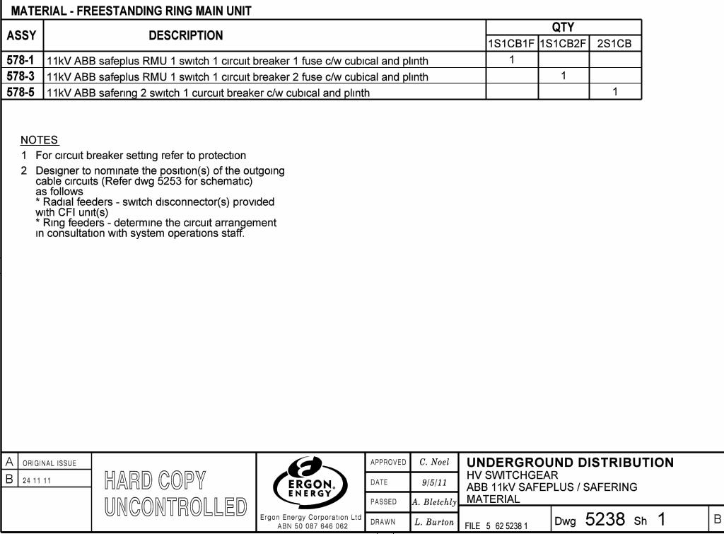
578-1
578-5
578-3
1
1.
MATERIAL - FREESTANDING RING MAIN UNIT
For circuit breaker setting refer to protection.
1S1CB1F 1S1CB2F 2S1CB
1
1
MATERIAL
9/5/11
1
11kV ABB safeplus RMU 1 switch 1 circuit breaker 1 fuse c/w cubical and plinth
11kV ABB safeplus RMU 1 switch 1 circuit breaker 2 fuse c/w cubical and plinth
11kV ABB safering 2 switch 1 curcuit breaker c/w cubical and plinth
ABB 11kV SAFEPLUS / SAFERING
HV SWITCHGEARB 24.11.11
B
2. Designer to nominate the position(s) of the outgoing cable circuits (Refer dwg 5253 for schematic) as follows:* Radial feeders - switch disconnector(s) provided with CFI unit(s)* Ring feeders - determine the circuit arrangement in consultation with system operations staff.
HARD COPYUNCONTROLLED�
�
�
���
�
�
�
�
�
�
�
�
�
�
�
�
�
A ORIGINAL ISSUE
�
�
�
���
�
�
�
�
�
�
��
�
�
�
�
�
��
�
����� �
��
�
�
�
�
��
�
�
�
�
���
�
�
�
�
�
�
�
�
�
�
�
�
�
�
�
�
�
�
�
�
�
�
�
�
�
�
�
�
�
������
�
��
�
�
�DRAWN
DATE
PASSED
APPROVED
Ergon Energy Corporation Ltd
ABN 50 087 646 062Dwg Sh
FILE: 5
UNDERGROUND DISTRIBUTION

���������� �����
�
�
�
L. Burton
HARD COPYUNCONTROLLED
62 5238 25238
C. Noel
A. Bletchly
9/5/11
2
CONSTRUCTION
Assy Selection
578-1, 3 or 5F
Lifting point
F
Lifting point
F
Lifting point
F
F
ABB 11kV SAFEPLUS / SAFERING
HV SWITCHGEAR�
�
�
�
�
�
�
�
�
�
�
�
A ORIGINAL ISSUE
�
�
�
�
�
�
��
�
�
�
�
�
��
�
����� �
��
�
�
�
�
��
�
�
�
�
���
�
�
�
�
�
�
�
�
�
�
�
�
�
�
�
�
�
�
�
�
�
�
�
�
�
�
�
�
�
������
�
��
�
�
�DRAWN
DATE
PASSED
APPROVED
Ergon Energy Corporation Ltd
ABN 50 087 646 062Dwg Sh
FILE: 5
UNDERGROUND DISTRIBUTION
���������� �����
�
�
�
L. Burton
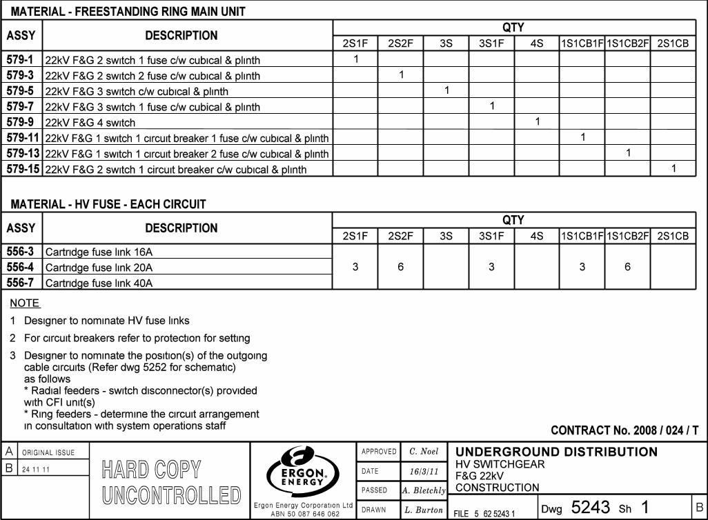
ASSY DESCRIPTIONQTY
16/3/11
579-9
62 5243 15243
C. Noel
A. Bletchly
579-1
579-5
579-3
579-7
579-11
1
2S1F 2S2F 3S1F3S 4S
MATERIAL - FREESTANDING RING MAIN UNIT
CONTRACT No. 2008 / 024 / T
CONSTRUCTION
22kV F&G 2 switch 1 fuse c/w cubical & plinth
579-13
579-15
22kV F&G 2 switch 2 fuse c/w cubical & plinth
22kV F&G 3 switch 1 fuse c/w cubical & plinth
22kV F&G 3 switch c/w cubical & plinth
22kV F&G 4 switch
22kV F&G 1 switch 1 circuit breaker 1 fuse c/w cubical & plinth
22kV F&G 1 switch 1 circuit breaker 2 fuse c/w cubical & plinth
22kV F&G 2 switch 1 circuit breaker c/w cubical & plinth
1S1CB1F 1S1CB2F 2S1CB
1
1
1
1
1
1
1
NOTE:
1.
1
Designer to nominate HV fuse links
F&G 22kV
2. For circuit breakers refer to protection for setting
556-3
556-4
556-7
Cartridge fuse link 16A
Cartridge fuse link 20A
Cartridge fuse link 40A
3 6 3 3 6
QTY
2S1F 2S2F 3S1F3S 4S 1S1CB1F 1S1CB2F 2S1CBASSY DESCRIPTION
MATERIAL - HV FUSE - EACH CIRCUIT
HV SWITCHGEARB 24.11.11
B
Designer to nominate the position(s) of the outgoing
cable circuits (Refer dwg 5252 for schematic)
as follows:
* Radial feeders - switch disconnector(s) provided
with CFI unit(s)
* Ring feeders - determine the circuit arrangement
in consultation with system operations staff.
3.
HARD COPYUNCONTROLLED�
�
�
���
�
�
�
�
�
�
�
�
�
�
�
�
�
A ORIGINAL ISSUE
�
�
�
���
�
�
�
�
�
�
��
�
�
�
�
�
��
�
����� �
��
�
�
�
�
��
�
�
�
�
���
�
�
�
�
�
�
�
�
�
�
�
�
�
�
�
�
�
�
�
�
�
�
�
�
�
�
�
�
�
������
�
��
�
�
�DRAWN
DATE
PASSED
APPROVED
Ergon Energy Corporation Ltd
ABN 50 087 646 062Dwg Sh
FILE: 5
UNDERGROUND DISTRIBUTION
���������� �����
�
�
�
L. Burton
HARD COPYUNCONTROLLED
62 5243 25243
C. Noel
A. Bletchly
HV SWITCHGEAR
F&G 22kV RING MAIN UNIT
CONTRACT No. 2008 / 024 / T
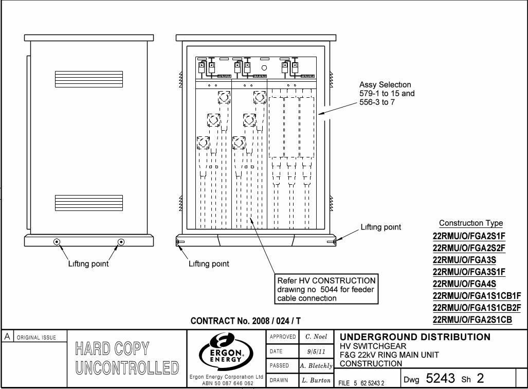
Construction Type
CONSTRUCTION
22RMU/O/FGA2S1F
22RMU/O/FGA2S2F
22RMU/O/FGA3S1F
22RMU/O/FGA2S1CB
22RMU/O/FGA3S
22RMU/O/FGA4S
22RMU/O/FGA1S1CB1F
22RMU/O/FGA1S1CB2F
Assy Selection
579-1 to 15 and
556-3 to 7
F
Refer HV CONSTRUCTION
drawing no. 5044 for feeder
cable connection
2
9/5/11
Lifting point
F
F
Lifting point
Lifting point
F
F
F
�
�
�
�
�
�
�
�
�
�
�
�
A ORIGINAL ISSUE
�
�
�
�
�
�
��
�
�
�
�
�
��
�
����� �
��
�
�
�
�
��
�
�
�
�
���
�
�
�
�
�
�
�
�
�
�
�
�
�
�
�
�
�
�
�
�
�
�
�
�
�
�
�
�
�
������
�
��
�
�
�DRAWN
DATE
PASSED
APPROVED
Ergon Energy Corporation Ltd
ABN 50 087 646 062Dwg Sh
FILE: 5
UNDERGROUND DISTRIBUTION

���������� �����
�
�
�
L. Burton
HARD COPYUNCONTROLLED
62 5252 15252
C. Noel
A. Bletchly
HV SWITCHGEAR
FEEDER
CABLE
FEEDER
CABLE
FEEDER
CABLE
F
F
Note:
(CFI) on this switch disconnector unit
Represents circuit fault indicator
FEEDER
CABLE
FEEDER
CABLE
FEEDER
CABLE
F
Note:
(CFI) on this switch disconnector unit
Represents circuit fault indicator
FEEDER
CABLE
FEEDER
CABLE
FEEDER
CABLE
FEEDER
CABLE
FEEDER
CABLE
F
Note:
(CFI) on this switch disconnector unit
Represents circuit fault indicator
1
SCHEMATIC
9/5/11F & G 22kV RING MAIN UNIT
2S1F 22kV F & G
ring main unit
2 switch, 1 fuse
2S2F 22kV F & G
ring main unit
2 switch, 2 fuse
3S1F 22kV F & G
ring main unit
3 switch, 1 fuse
F F F
�
�
�
���
�
�
�
�
�
�
�
�
�
�
�
�
�
A ORIGINAL ISSUE
�
�
�
���
�
�
�
�
�
�
��
�
�
�
�
�
��
�
����� �
��
�
�
�
�
��
�
�
�
�
���
�
�
�
�
�
�
�
�
�
�
�
�
�
�
�
�
�
�
�
�
�
�
�
�
�
�
�
�
�
������
�
��
�
�
�DRAWN
DATE
PASSED
APPROVED
Ergon Energy Corporation Ltd
ABN 50 087 646 062Dwg Sh
FILE: 5
UNDERGROUND DISTRIBUTION

���������� �����
�
�
�
L. Burton
10/3/11HARD COPYUNCONTROLLED
62 5252 25252
C. Noel
A. Bletchly
HV SWITCHGEAR
FEEDER
CABLE
FEEDER
CABLE
FEEDER
CABLE
F
Note:
(CFI) on this switch disconnector unit
Represents circuit fault indicator
2
FEEDER
CABLE
FEEDER
CABLE
FEEDER
CABLE
FEEDER
CABLE
F
Note:
(CFI) on this switch disconnector unit
Represents circuit fault indicator
SCHEMATIC
F & G 22kV RING MAIN UNIT
4S 22kV F & G
ring main unit
4 switch
3S 22kV F & G
ring main unit
3 switch
F F F F
�
�
�
�
�
�
�
�
�
�
�
�
A ORIGINAL ISSUE
�
�
�
�
�
�
��
�
�
�
�
�
��
�
����� �
��
�
�
�
�
��
�
�
�
�
���
�
�
�
�
�
�
�
�
�
�
�
�
�
�
�
�
�
�
�
�
�
�
�
�
�
�
�
�
�
������
�
��
�
�
�DRAWN
DATE
PASSED
APPROVED
Ergon Energy Corporation Ltd
ABN 50 087 646 062Dwg Sh
FILE: 5
UNDERGROUND DISTRIBUTION
���������� �����
�
�
�
L. Burton
HARD COPYUNCONTROLLED
62 5252 35252
C. Noel
A. Bletchly
HV SWITCHGEAR
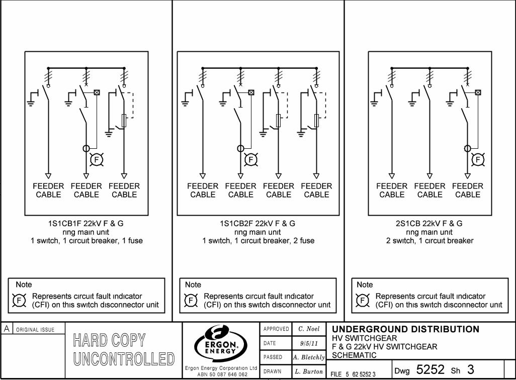
F & G 22kV HV SWITCHGEAR
FEEDER
CABLE
FEEDER
CABLE
FEEDER
CABLE
F
Note:
(CFI) on this switch disconnector unit
Represents circuit fault indicator F
Note:
(CFI) on this switch disconnector unit
Represents circuit fault indicator F
Note:
Represents circuit fault indicator
F
FEEDER
CABLE
FEEDER
CABLE
FEEDER
CABLE
F F
FEEDER
CABLE
FEEDER
CABLE
FEEDER
CABLE
FEEDER
CABLE
3
9/5/11
1S1CB1F 22kV F & G
ring main unit
1 switch, 1 circuit breaker, 1 fuse
(CFI) on this switch disconnector unit
1S1CB2F 22kV F & G
ring main unit
1 switch, 1 circuit breaker, 2 fuse
2S1CB 22kV F & G
ring main unit
2 switch, 1 circuit breaker
SCHEMATIC
�
�
�
���
�
�
�
�
�
�
�
�
�
�
�
�
�
A ORIGINAL ISSUE
�
�
�
���
�
�
�
�
�
�
��
�
�
�
�
�
��
�
����� �
��
�
�
�
�
��
�
�
�
�
���
�
�
�
�
�
�
�
�
�
�
�
�
�
�
�
�
�
�
�
�
�
�
�
�
�
�
�
�
�
������
�
��
�
�
�DRAWN
DATE
PASSED
APPROVED
Ergon Energy Corporation Ltd
ABN 50 087 646 062Dwg Sh
FILE: 5
UNDERGROUND DISTRIBUTION
���������� �����
�
�
�
L. Burton
HARD COPYUNCONTROLLED
62 5253 15253
C. Noel
A. Bletchly
HV SWITCHGEAR
FEEDER
CABLE
FEEDER
CABLE
FEEDER
CABLE
F
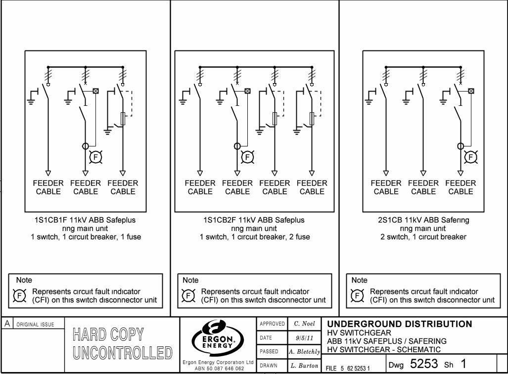
Note:
(CFI) on this switch disconnector unit
Represents circuit fault indicator F
Note:
(CFI) on this switch disconnector unit
Represents circuit fault indicator F
Note:
Represents circuit fault indicator
F
FEEDER
CABLE
FEEDER
CABLE
FEEDER
CABLE
F F
FEEDER
CABLE
FEEDER
CABLE
FEEDER
CABLE
FEEDER
CABLE
1
9/5/11
(CFI) on this switch disconnector unit
HV SWITCHGEAR - SCHEMATIC
1S1CB1F 11kV ABB Safeplus
ring main unit
1 switch, 1 circuit breaker, 1 fuse
1S1CB2F 11kV ABB Safeplus
ring main unit
1 switch, 1 circuit breaker, 2 fuse
2S1CB 11kV ABB Safering
ring main unit
2 switch, 1 circuit breaker
ABB 11kV SAFEPLUS / SAFERING
�
�
�
���
�
�
�
�
�
�
�
�
�
�
�
�
�
A ORIGINAL ISSUE
�
�
�
���
�
�
�
�
�
�
��
�
�
�
�
�
��
�
����� �
��
�
�
�
�
��
�
�
�
�
���
�
�
�
�
�
�
�
�
�
�
�
�
�
�
�
�
�
�
�
�
�
�
�
�
�
�
�
�
�
������
�
��
�
�
�DRAWN
DATE
PASSED
APPROVED
Ergon Energy Corporation Ltd
ABN 50 087 646 062Dwg Sh
FILE: 5
UNDERGROUND DISTRIBUTION
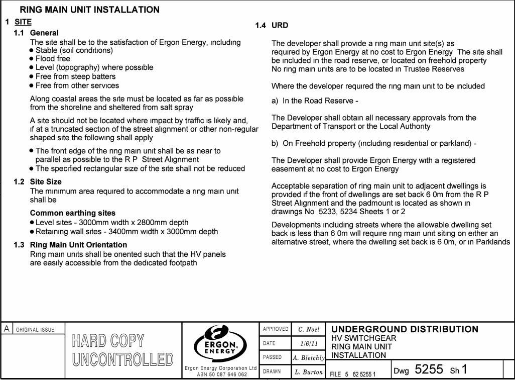
1 SITE
INSTALLATION
General1.1
Stable (soil conditions)
Free from steep batters
Flood free
Level (topography) where possible
1.4
1.2
1
1/6/11
Site Size
1.3
URD
Along coastal areas the site must be located as far as possible
from the shoreline and sheltered from salt spray.
Common earthing sites
Level sites - 3000mm width x 2800mm depth.
Retaining wall sites - 3400mm width x 3000mm depth.
The site shall be to the satisfaction of Ergon Energy, including
A site should not be located where impact by traffic is likely and,
if at a truncated section of the street alignment or other non-regular
shaped site the following shall apply:
The specified rectangular size of the site shall not be reduced.
a) In the Road Reserve:-
The Developer shall obtain all necessary approvals from the
Department of Transport or the Local Authority.
b) On Freehold property (including residential or parkland):-
The Developer shall provide Ergon Energy with a registered
easement at no cost to Ergon Energy.
HARD COPYUNCONTROLLED
L. Burton
A. Bletchly
C. Noel
62 5255 15255
HV SWITCHGEAR
RING MAIN UNIT
The minimum area required to accommodate a ring main unit
shall be:
Ring Main Unit Orientation
The developer shall provide a ring main unit site(s) as
required by Ergon Energy at no cost to Ergon Energy. The site shall
be included in the road reserve, or located on freehold property.
No ring main units are to be located in Trustee Reserves.
Where the developer required the ring main unit to be included:
Acceptable separation of ring main unit to adjacent dwellings is
provided if the front of dwellings are set back 6.0m from the R.P.
Street Alignment and the padmount is located as shown in
drawings No. 5233, 5234 Sheets 1 or 2.
Developments including streets where the allowable dwelling set
back is less than 6.0m will require ring main unit siting on either an
alternative street, where the dwelling set back is 6.0m, or in Parklands.
RING MAIN UNIT INSTALLATION
Free from other services
The front edge of the ring main unit shall be as near to
parallel as possible to the R.P. Street Alignment.
Ring main units shall be oriented such that the HV panels
are easily accessible from the dedicated footpath.
�
�
�
���
�
�
�
�
�
�
�
�
�
�
�
�
�
A ORIGINAL ISSUE
�
�
�
���
�
�
�
�
�
�
��
�
�
�
�
�
��
�
����� �
��
�
�
�
�
��
�
�
�
�
���
�
�
�
�
�
�
�
�
�
�
�
�
�
�
�
�
�
�
�
�
�
�
�
�
�
�
�
�
�
������
�
��
�
�
�DRAWN
DATE
PASSED
APPROVED
Ergon Energy Corporation Ltd
ABN 50 087 646 062Dwg Sh
FILE: 5
UNDERGROUND DISTRIBUTION

�
2
1 SITE
1.5
(CONT’D)
Commercial and Industrial or Landscaped Areas
1.6 Parklands - for other than URD
1.7
Cabling Only
Cabling and Access
2 SITE PREPARATION
Sites shall be prepared in accordance with the included
construction drawings.
3 CONSTRUCTION OF RETAINING WALLS
4
4.1 Uniculvert
Cabling and Access Requirement
A 3.0m wide easement, or road reserve, from the front of
the site is required for cabling and access.
��
62 5255 25255
HV SWITCHGEAR
INSTALLATION
RING MAIN UNIT
1/6/11
C. Noel
A. Bletchly
L. Burton
Whether the ring main unit is for the sole use of that
complex, or is required as part of the distribution network, the
owner is required to grant Ergon Energy an easement for the
ring main unit site, access and cabling.
Obtain the necessary approval for an easement to accommodate
the ring main unit, cabling and access to site.
Acceptable separation of ring main unit to adjacent dwellings is
shown in drawings No. 5234 Sheets 1 & 2.
Should the cabling route not be available in conjunction with
access, a 1.0m wide cable easement is required to the front
of the ring main unit. Additionally 2.0m x 3.0m (ring main unit
site width) is required immediately in front to allow spreading of
cables for entry to the ring main unit and also include the buried
earth cable.
Retaining walls shall be constructed around the perimeter of a
ring main unit site where:
A change in ground level of 300mm or more occurs within 2.0m
of the boundary of the ring main unit site.
RING MAIN UNIT FOUNDATION
Separation of 5.0m between ring main unit and the
nearest room or habitable area should be provided
where possible.
Uniculvert foundations shall not be constructed where site and
ground conditions do not provide an even or equal bearing
capacity for the ring main unit.
Uniculvert foundations for stable soil conditions shall
be constructed in accordance with Drawing No. 5232.
HARD COPYUNCONTROLLED
�
�
�
�
�
�
�
�
�
�
�
�
A ORIGINAL ISSUE
�
�
�
�
�
�
��
�
�
�
�
�
��
�
����� �
��
�
�
�
�
��
�
�
�
�
���
�
�
�
�
�
�
�
�
�
�
�
�
�
�
�
�
�
�
�
�
�
�
�
�
�
�
�
�
�
������
�
��
�
�
�DRAWN
DATE
PASSED
APPROVED
Ergon Energy Corporation Ltd
ABN 50 087 646 062Dwg Sh
FILE: 5
UNDERGROUND DISTRIBUTION

�
INSTALLATION
3
4 (CONT’D)
Unstable Sites
Where sites are very unstable, and conventional foundation
construction techniques as described in this document cannot
be applied, a special design shall be required.
5 BACKFILLING AND FINAL SITE FINISH
5.1 Common Earthing Sites
6
6.1
ADDITIONAL REQUIREMENTS
Commercial and Industrial Installation
All backfill of the site must be compacted before final site finish in
accordance with the applicable drawing.
Easy access for a mobile crane must be available for the purpose of
installation or replacement.
Ergon Energy cable conduits for the development may be placed in
the substation site and shall pass down the sides of the uniculvert
foundation. No conduits shall pass through or under the uniculvert
foundation. Conduits shall be 750mm minimum depth below the
finished surface level. The substation site surface is to be finished
with a concrete slab (refer to drawing No. 5004). The 2.0m apron in
front of the substation cabinet shall be finished with a concrete slab
sectioned with construction joints for ease of future removal.
6.2
An additional 2.0m apron shall be provided in front of, and for the
full width of the site (ie 4.8m depth). This will provide a safe
working platform and access around latched open doors for
emergency operations.
C. Noel
A. Bletchly
1/6/11
L. Burton 26 5255 35255
RING MAIN UNIT FOUNDATION
In such circumstances, the developer shall obtain a certified
design from a Civil Engineer (RPEQ) for Ergon Energy’s
consideration. No special designs for ring main unit
foundation construction shall be used without the approval of
Ergon Energy.
The preferred location of ring main unit sites at
commercial and industrial developments is at the real property
street alignment. Switchgear cabinet doors shall face the
adjoining footpath.
Ring main units shall be located on the development in
areas where clear, all weather access is provided for personnel
and heavy equipment at all times.
Ring Main Units in Landscaped Areas
Where the ring main unit is located in a landscaped
area (gardens) the following shall apply:
The ring main unit site surface is to be finished with a concrete slab
(refer to drawing No. 5217).
The 2.0m apron in front of the ring main unit site shall be finished with
a concrete slab sectioned with construction joints for ease of future
removal.
HV SWITCHGEAR
RING MAIN UNIT
4.2
Sealing of the cable apertures in the precast concrete plinth
and construction of the concrete surround slab over the
ground surface shall be in accordance with drawing No. 5217.
Should the site be located in restricted areas such as carparks
and between buildings, an additional minimum 2.0m of clear
access shall be provided in front of, and for the full width of
the site (ie 4.8m depth). This will provide a safe working
platform and access around latched open doors for
emergency operations.
HARD COPYUNCONTROLLED�
�
�
���
�
�
�
�
�
�
�
�
�
�
�
�
�
A ORIGINAL ISSUE
�
�
�
���
�
�
�
�
�
�
��
�
�
�
�
�
��
�
����� �
��
�
�
�
�
��
�
�
�
�
���
�
�
�
�
�
�
�
�
�
�
�
�
�
�
�
�
�
�
�
�
�
�
�
�
�
�
�
�
�
������
�
��
�
�
�DRAWN
DATE
PASSED
APPROVED
Ergon Energy Corporation Ltd
ABN 50 087 646 062Dwg Sh
FILE: 5
UNDERGROUND DISTRIBUTION

�INSTALLATION
4
6.2 (CONT’D)
6.3
7
Ring Main Unit in Landscaped Areas
When planting vegetation in landscaped areas and gardens,
ensure vegetation does not encroach on the ring main unit
site. Take into consideration the fully matured size
of vegetation to allow continuing access to the site.
Ergon Energy cable conduits for the development may be
placed in the ring main unit site and shall pass down the sides
of the uniculvert foundation. No conduits shall pass through
or under the uniculvert foundation. Conduits shall be 750mm
minimum depth below the finished surface level.
Ring Main Units Installation in Parklands
Where the ring main unit is located in Council
Parklands, the installation shall be in accordance with the
requirements of drawing No. 5234 Sheets 1 or 2.
A 2.0m apron as specified in Clause 6.2 shall be provided.
No buildings/residences, fences, including their foundations, LV
switchboard earths, or metalic objects are permitted within the
clearance zone around the RING MAIN UNIT.
Clearance to Telstra assets shall be as noted on EARTHING
drawing No. 5221 Sheet 1.
62 5255 45255
HV SWITCHGEAR
RING MAIN UNIT
1/6/11
C. Noel
A. Bletchly
L. Burton
SPACING BETWEEN RING MAIN UNIT AND OTHER
METAL OBJECTS
HARD COPYUNCONTROLLED
�
�
�
�
�
�
�
�
�
�
�
�
A ORIGINAL ISSUE
�
�
�
�
�
�
��
�
�
�
�
�
��
�
����� �
��
�
�
�
�
��
�
�
�
�
���
�
�
�
�
�
�
�
�
�
�
�
�
�
�
�
�
�
�
�
�
�
�
�
�
�
�
�
�
�
������
�
��
�
�
�DRAWN
DATE
PASSED
APPROVED
Ergon Energy Corporation Ltd
ABN 50 087 646 062Dwg Sh
FILE: 5
UNDERGROUND DISTRIBUTION