
RMT-V257D/V257E SERVICE MANUAL France … SLV-SE210 SLV-SE210B/SE210D/SE210G/ SX110A/SX110B...
52
Photo: SLV-SE210 SLV-SE210B/SE210D/SE210G/ SX110A/SX110B RMT-V257D/V257E SERVICE MANUAL France Model SLV-SE210B/SX110B Italy Model Germany Model North Europe Model SLV-SE210D/SX110A UK Model SLV-SE210G VIDEO CASSETTE RECORDER SPECIFICATIONS Refer to the SERVICE MANUAL of VHS MECHANICAL ADJUSTMENT MANUAL VII for MECHANICAL ADJUSTMENTS. (9-921-790-11) TS-10 MECHANISM System Channel coverage PAL (I): (SLV-SE210G) UHF B21 to B69 PAL (B/G) (SLV-SE210B/SE210D/SX110B/ SX110A): VHF E2 to E12 Italiens VHF A to H UHF E21 to E69 CATV S01 to S05, S1 to S20 HYPER S21 to S41 SECAM (L) (SLV-SE210B/SX110B): VHF F2 to F10 UHF F21 to F69 CATV B to Q HYPER S21 to S41 RF output signal (SLV-SE210G/SE210D/SX110D) UHF channels 21 to 69 Aerial out 75-ohm asymmetrical aerial socket Tape speed SP: PAL 23.39 mm/s (recording/playback) NTSC 33.35 mm/s (playback only) SECAM (SLV-SE210B/SX110B) 23.39 mm/s (recording/playback) MESECAM (SLV-SE210B/SE210D/SX110B/ SX110D) 23.39 mm/s (recording/playback) LP: PAL (SLV-SE210G) 11.70 mm/s (recording/playback) NTSC (SLV-SE210G) 16.67 mm/s (playback only) Maximum recording/playback time 10 hrs. in LP mode (with E300 tape) (SLV-SE210G) 5 hrs. in SP mode (with E300 tape) Rewind time Approx. 60 sec. (with E180 tape) Inputs and outputs AV1 (EURO AV) 21-pin Video input: pin 20 Audio input: pins 2 and 6 Video output: pin 19 Audio output: pins 1 and 3 AV2 IN (SLV-SE210B/SE210D) 21-pin Video input: pin 20 Audio input: pins 2 and 6 General Power requirements 240 V: (SLV-SE210G) 230 V: (SLV-SE210B/SE210D/ SX110A/SX110B) AC, 50 Hz Power consumption 15 W 3 W (ECO. MODE is set to ON, Standby mode) Operating temperature 5 C to 40 C Storage temperature –20 C to 60 C Dimensions Approx. 360 × 94 × 255 mm (w/h/d) including projecting parts and controls Mass Approx. 2.8 kg (SLV-SE210G) Approx. 2.6 kg (SLV-SE210B/ SE210D/SX110A/SX110B) Supplied accessories Remote commander (1) R6 (size AA) batteries (2) Aerial cable (1) PERITEL cable (1) (SLV-SE210B/SX110B) Design and specifications are subject to change without notice.
Transcript of RMT-V257D/V257E SERVICE MANUAL France … SLV-SE210 SLV-SE210B/SE210D/SE210G/ SX110A/SX110B...

Photo: SLV-SE210
SLV-SE210B/SE210D/SE210G/SX110A/SX110B
RMT-V257D/V257E
SERVICE MANUAL France ModelSLV-SE210B/SX110B
Italy ModelGermany Model
North Europe ModelSLV-SE210D/SX110A
UK ModelSLV-SE210G
VIDEO CASSETTE RECORDER
SPECIFICATIONS
Refer to the SERVICE MANUAL of VHS
MECHANICAL ADJUSTMENT MANUAL
VII for MECHANICAL ADJUSTMENTS.
(9-921-790-11)
TS-10 MECHANISM
SystemChannel coverage
PAL (I): (SLV-SE210G)UHF B21 to B69
PAL (B/G)(SLV-SE210B/SE210D/SX110B/SX110A):
VHF E2 to E12Italiens VHF A to HUHF E21 to E69CATV S01 to S05, S1 to S20HYPER S21 to S41
SECAM (L) (SLV-SE210B/SX110B):
VHF F2 to F10UHF F21 to F69CATV B to QHYPER S21 to S41
RF output signal (SLV-SE210G/SE210D/SX110D)
UHF channels 21 to 69Aerial out
75-ohm asymmetrical aerial socketTape speed
SP: PAL 23.39 mm/s(recording/playback)
NTSC 33.35 mm/s(playback only)
SECAM (SLV-SE210B/SX110B)
23.39 mm/s(recording/playback)
MESECAM (SLV-SE210B/SE210D/SX110B/SX110D)
23.39 mm/s(recording/playback)
LP: PAL (SLV-SE210G)11.70 mm/s (recording/playback)
NTSC (SLV-SE210G)16.67 mm/s(playback only)
Maximum recording/playback time10 hrs. in LP mode (with E300 tape)(SLV-SE210G)5 hrs. in SP mode (with E300 tape)
Rewind timeApprox. 60 sec. (with E180 tape)
Inputs and outputsAV1 (EURO AV)
21-pinVideo input: pin 20Audio input: pins 2 and 6Video output: pin 19Audio output: pins 1 and 3
AV2 IN (SLV-SE210B/SE210D)21-pinVideo input: pin 20Audio input: pins 2 and 6
GeneralPower requirements
240 V: (SLV-SE210G)230 V: (SLV-SE210B/SE210D/SX110A/SX110B)AC, 50 Hz
Power consumption15 W3 W (ECO. MODE is set to ON,Standby mode)
Operating temperature5 C to 40 C
Storage temperature–20 C to 60 C
DimensionsApprox. 360 × 94 × 255 mm (w/h/d)including projecting parts and controls
MassApprox. 2.8 kg (SLV-SE210G)Approx. 2.6 kg (SLV-SE210B/SE210D/SX110A/SX110B)
Supplied accessoriesRemote commander (1)R6 (size AA) batteries (2)Aerial cable (1)PERITEL cable (1) (SLV-SE210B/SX110B)
Design and specifications are subject tochange without notice.
– 2 –
1. Check the area of your repair for unsoldered or poorly-soldered connections. Check the entire board surface forsolder splashes and bridges.
2. Check the interboard wiring to ensure that no wires are"pinched" or contact high-wattage resistors.
3. Look for unauthorized replacement parts, par-ticularlytransistors, that were installed during a previous repair.Point them out to the customer and recommend theirreplacement.
4. Look for parts which, through functioning, show obvioussigns of deterioration. Point them out to the customer andrecommend their replace-ment.
5. Check the line cord for cracks and abrasion.Recommend the replacement of any such line cord to thecustomer.
6. Check the B+ voltage to see it is at the values specified.6. Check the antenna terminals, metal trim, “metallized”
knobs, screws, and all other exposed metal parts for ACleakage.Check leakage as described below.
LEAKAGE TEST
The AC leakage form any exposed metal parts to earth groundand from all exposed metal parts to any exposed metal parthaving a return to chassis, must not exceed 0.5mA (500microampers).Leakage current can be measured by any one of three methods.
1. A commercial leakage tester, such as Simpson 229 or RCAWT-540A. Follow the manufactures' instructions to use theseinstruments.
2. A battery operated AC milliammerter. The Data Precision245 digital multimeter is suitable for this job.
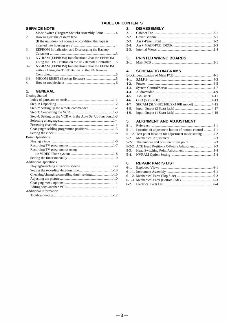
3. Measuring the voltage drop across a resistor by means of aVOM or battery-operated AC voltmeter. The “limit”indication is 0.75V, so analog meters must have an accuratelowvoltage scale. The Simpson 250 and Sanwa SH-63Trd areexamples of a passive VOM that is suitable. Nearly all batteryoperated digital multimeters that have a 2V AC range aresuitable. (See Fig. A)
SAFETY CHECK-OUT
After correcting the original service problem, perform the following
safety checks before releasing the set to the customer.
SAFETY-RELATED COMPONENT WARNING!!
COMPONENTS IDENTIFIED BY MARK ! OR DOTTED LINEWITH MARK ! ON THE SCHEMATIC DIAGRAMS AND IN THEPARTS LIST ARE CRITICAL TO SAFE OPERATION. REPLACETHESE COMPONENTS WITH SONY PARTS WHOSE PARTNUMBERS APPEAR AS SHOWN IN THIS MANUAL OR INSUPPLEMENTS PUB-LISHED BY SONY.
To Exposed Metal Parts on Set
0.15 µF 1.5 kΩACVoltmeter(0.75 V)
Earth Ground
Fig. A. Using an AC voltmeter to check AC leakage.
– 3 –
TABLE OF CONTENTSSERVICE NOTE1. Mode Switch (Program Switch) Assembly Point ............. 42. How to eject the cassette tape
(If the unit does not operate on condition that tape isinserted into housing ass'y) ............................................... 4
3. EEPROM Initialization and Discharging the BackupCapacitor ............................................................................5
3-1. NV-RAM (EEPROM) Initialization Clear the EEPROMUsing the TEST Button on the JIG Remote Controller......5
3-2. NV-RAM (EEPROM) Initialization Clear the EEPROMwithout Using the TEST Button on the JIG RemoteController............................................................................5
3-3. MICOM RESET (Backup Release) ...................................54. How to troubleshoot ......................................................... 6
1. GENERALGetting Started
Index of parts and controls ....................................................1-1Step 1: Unpacking .................................................................1-2Step 2: Setting up the remote commander.............................1-2Step 3: Connecting the VCR .................................................1-3Step 4: Setting up the VCR with the Auto Set Up function ..1-3Selecting a language..............................................................1-4Presetting channels ................................................................1-4Changing/disabling programme positions.............................1-5Setting the clock ....................................................................1-6
Basic OperationsPlaying a tape ........................................................................1-6Recording TV programmes ...................................................1-7Recording TV programmes using
the VIDEO Plus+ system .................................................1-8Setting the timer manually ....................................................1-9
Additional OperationsPlaying/searching at various speeds ......................................1-9Setting the recording duration time .....................................1-10Checking/changing/cancelling timer settings......................1-10Adjusting the picture ...........................................................1-10Changing menu options.......................................................1-11Editing with another VCR...................................................1-11
Additional InformationTroubleshooting...................................................................1-12
2. DISASSEMBLY2-1. Cabinet Top ................................................................... 2-12-2. Cover Bottom ................................................................ 2-12-3. Ass’y-Panel Front .......................................................... 2-22-4. Ass’y MAIN-PCB, DECK ............................................ 2-32-5. Internal Views ............................................................... 2-4
3. PRINTED WIRING BOARDS3-1. Main PCB ...................................................................... 3-1
4. SCHEMATIC DIAGRAMSBlock Identification of Main PCB ............................................ 4-14-1. S.M.P.S. ........................................................................ 4-34-2. Power ............................................................................ 4-54-3. System Control/Servo ................................................... 4-74-4. Audio/Video .................................................................. 4-94-5. TM-Block .....................................................................4-114-6. OSD (VPS/PDC) ......................................................... 4-134-7 SECAM (SLV-SE210B/SX110B model) .....................4-154-8. Input-Output (2 Scart Jack) ......................................... 4-174-9. Input-Output (1 Scart Jack) ......................................... 4-19
5. ALIGNMENT AND ADJUSTMENT5-1. Reference .......................................................................5-15-1-1 Location of adjustment button of remote control .......... 5-15-1-2. Test point location for adjustment mode setting ........... 5-25-2. Mechanical Adjustment ................................................ 5-35-2-1. The number and position of test point .......................... 5-35-2-2. ACE Head Position (X-Point) Adjustment ................... 5-35-3. Head Switching Point Adjustment ................................ 5-45-4. NVRAM Option Setting ............................................... 5-4
6. REPAIR PARTS LIST6-1. Exploded Views ............................................................ 6-16-1-1. Instrument Assembly .................................................... 6-16-1-2. Mechanical Parts (Top Side) ......................................... 6-26-1-3. Mechanical Parts (Bottom Side) ................................... 6-36-2. Electrical Parts List ....................................................... 6-4
– 4 –
SERVICE NOTE
1. MODE SWITCH (PROGRAM SWITCH) ASSEMBLY POINT
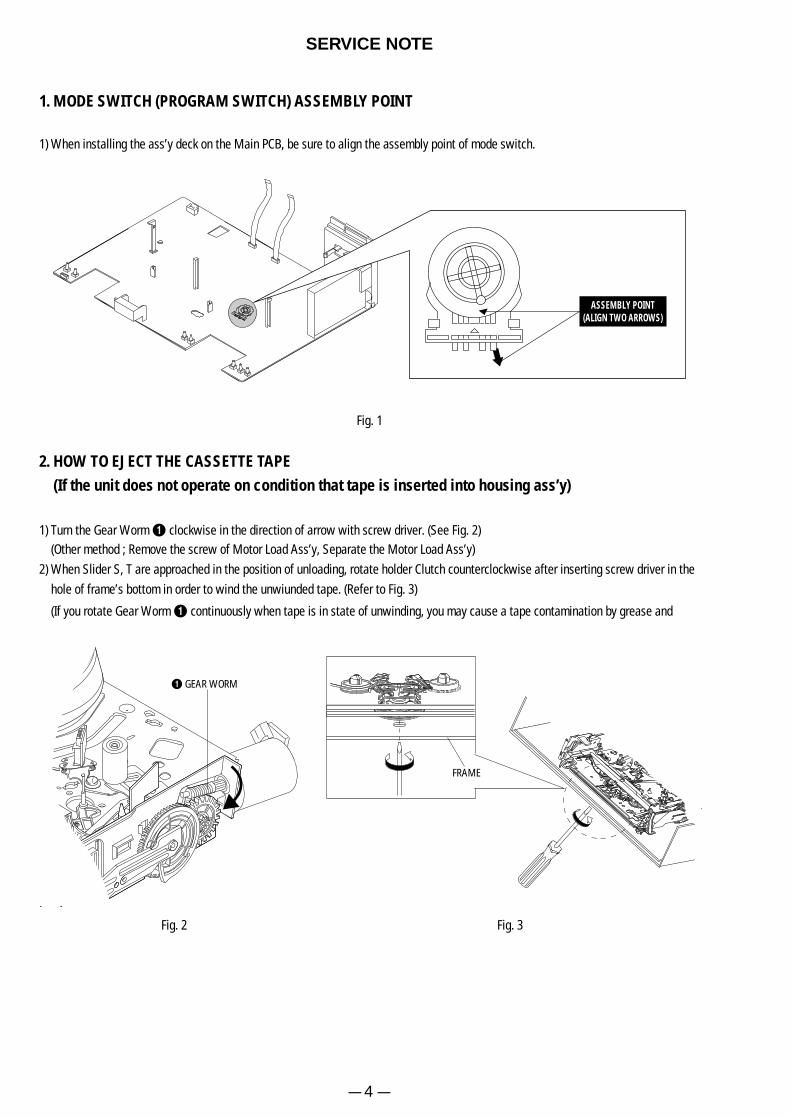
1) When installing the ass’y deck on the Main PCB, be sure to align the assembly point of mode switch.
ASSEMBLY POINT(ALIGN TWO ARROWS)
Fig. 1
2. HOW TO EJECT THE CASSETTE TAPE(If the unit does not operate on condition that tape is inserted into housing ass’y)
1) Turn the Gear Worm Œ clockwise in the direction of arrow with screw driver. (See Fig. 2)(Other method ; Remove the screw of Motor Load Ass’y, Separate the Motor Load Ass’y)
2) When Slider S, T are approached in the position of unloading, rotate holder Clutch counterclockwise after inserting screw driver in the
hole of frame’s bottom in order to wind the unwiunded tape. (Refer to Fig. 3)
(If you rotate Gear Worm Πcontinuously when tape is in state of unwinding, you may cause a tape contamination by grease and
Fig. 2 Fig. 3
ΠGEAR WORM
FRAME
– 5 –
3. EEPROM INITIALIZATION AND DISCHARGING THE BACKUP CAPACITOR3-1. NV-RAM (EEPROM) Initialization Clear the EEPROM Using the TEST Button on the JIG Remote Controller1) Plug the VCR into the mains.
Switch on the VCR by pressing (ON/STANDBY) on the remote controller.
2) Press (TEST) button on the JIG remote controller and released.
3) Within 2 seconds, press the (CLEAR) button on the remote controller.
Result: The EEPROM will be cleared.
4) During the clearing, the “TEST” indication flashes on the front of the VCR.
The process will finish after a few seconds.(2-3 seconds)
5) After exiting the display “TEST” to normal display.
6) Press the (ON/STANDBY) button to switch off the VCR.
7) Disconnect the power supply the VCR.
It is important that you make sure ;
Do not plug the VCR into the mains after clearing EEPROM to ensure that Auto set up procedure works correctry for end users.
3-2. NV-RAM (EEPROM) Initialization Clear the EEPROM without Using the TEST Button on the JIG Remote Controller1) Plug the VCR into the mains.
Switch on the VCR by pressing (ON/STANDBY) on the remote controller.
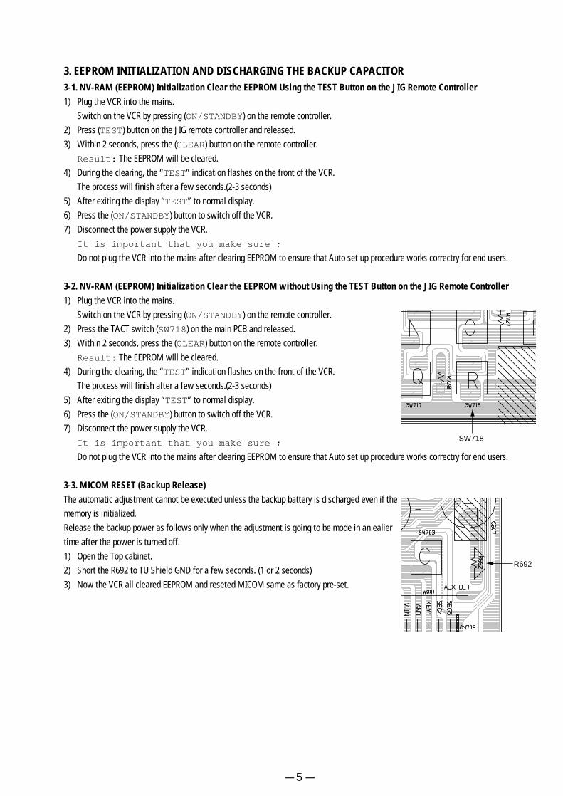
2) Press the TACT switch (SW718) on the main PCB and released.
3) Within 2 seconds, press the (CLEAR) button on the remote controller.
Result: The EEPROM will be cleared.
4) During the clearing, the “TEST” indication flashes on the front of the VCR.
The process will finish after a few seconds.(2-3 seconds)
5) After exiting the display “TEST” to normal display.
6) Press the (ON/STANDBY) button to switch off the VCR.
7) Disconnect the power supply the VCR.
It is important that you make sure ;
Do not plug the VCR into the mains after clearing EEPROM to ensure that Auto set up procedure works correctry for end users.
3-3. MICOM RESET (Backup Release)The automatic adjustment cannot be executed unless the backup battery is discharged even if the
memory is initialized.
Release the backup power as follows only when the adjustment is going to be mode in an ealier
time after the power is turned off.
1) Open the Top cabinet.
2) Short the R692 to TU Shield GND for a few seconds. (1 or 2 seconds)
3) Now the VCR all cleared EEPROM and reseted MICOM same as factory pre-set.
R692
SW718
– 6 –
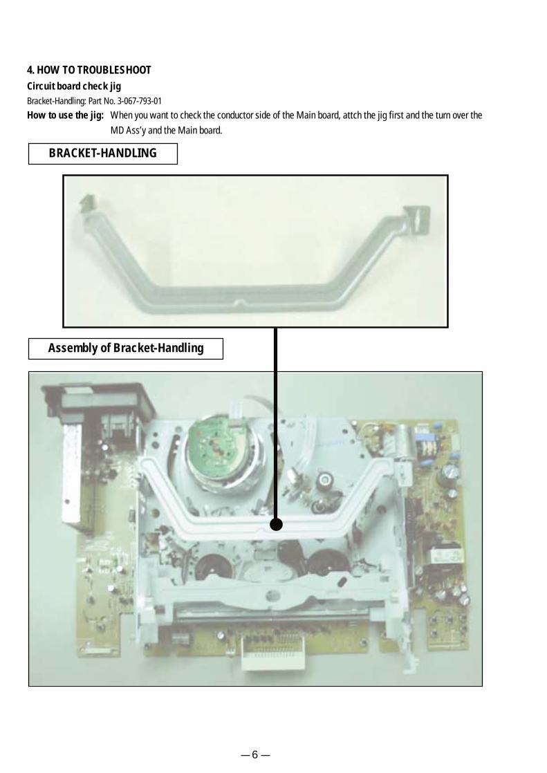
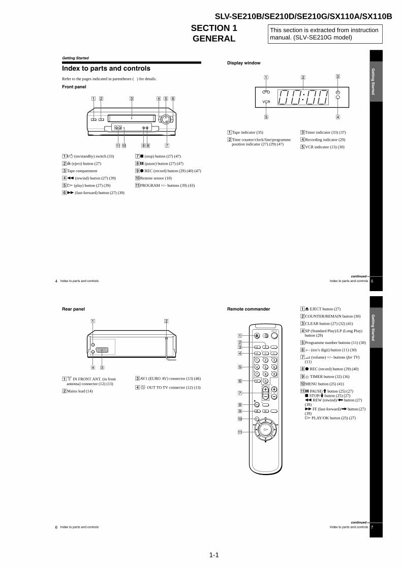
4. HOW TO TROUBLESHOOTCircuit board check jigBracket-Handling: Part No. 3-067-793-01
How to use the jig: When you want to check the conductor side of the Main board, attch the jig first and the turn over the
MD Ass’y and the Main board.
BRACKET-HANDLING
Assembly of Bracket-Handling

– 7 –
BRACKET-HANDLING Twist

– 8 –
MEMO
Gettin
g S
tarted
5Index to parts and controls
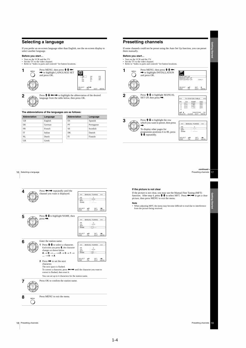
Display window
ATape indicator (35)
BTime counter/clock/line/programme position indicator (27) (29) (47)
CTimer indicator (33) (37)
DRecording indicator (29)
EVCR indicator (13) (30)
continued
Gettin
g S
tarted
7Index to parts and controls
Remote commander AZ EJECT button (27)
BCOUNTER/REMAIN button (30)
CCLEAR button (27) (32) (41)
DSP (Standard Play)/LP (Long Play) button (29)
EProgramme number buttons (11) (30)
F- (ten’s digit) button (11) (30)
G2 (volume) +/– buttons (for TV) (11)
Hz REC (record) button (29) (40)
I TIMER button (32) (36)
JMENU button (25) (41)
KX PAUSE/M button (25) (27)x STOP/m button (25) (27)m REW (rewind)/< button (27) (39)M FF (fast-forward)/, button (27) (39)H PLAY/OK button (25) (27)
1 2 3
4 5 6
7 8 9
0
continued
6 Index to parts and controls
Rear panel
A8 IN FRONT ANT. (in front antenna) connector (12) (13)
BMains lead (14)
CAV1 (EURO AV) connector (13) (46)
D OUT TO TV connector (12) (13)
1-1
4 Index to parts and controls
Getting Started
Index to parts and controlsRefer to the pages indicated in parentheses ( ) for details.
Front panel
A?/1 (on/standby) switch (33)
BA (eject) button (27)
CTape compartment
Dm (rewind) button (27) (39)
EH (play) button (27) (39)
FM (fast-forward) button (27) (39)
Gx (stop) button (27) (47)
HX (pause) button (27) (47)
Iz REC (record) button (29) (40) (47)
JRemote sensor (10)
KPROGRAM +/– buttons (39) (43)
SECTION 1GENERAL
SLV-SE210B/SE210D/SE210G/SX110A/SX110B
This section is extracted from instructionmanual. (SLV-SE210G model)

1-2
8 Index to parts and controls
L[TV] / [VIDEO] remote control switch (10)
M?/1 (on/standby) switch (11) (33)
NINPUT SELECT button (30) (37) (47)
Ot TV/VIDEO button (11) (13) (30)
P DISPLAY button (30)
QPROG (programme) +/– buttons (11) (29)
RWIDE button (for TV) (11)
Sy SLOW button (39)
T×2 button (39)
1 2 3
4 5 6
7 8 9
0
Gettin
g S
tarted
9Unpacking
Step 1 : Unpacking
Check that you have received the following items with the VCR:
• Remote commander • Aerial cable
• R6 (size AA) batteries
Gettin
g S
tarted
11Setting up the remote commander
TV control buttons
Notes• With normal use, the batteries should last about three to six months. • If you do not use the remote commander for an extended period of time, remove
the batteries to avoid possible damage from battery leakage.• Do not use a new battery together with an old one.• Do not use different types of batteries together.• Some buttons may not work with certain Sony TVs.
To Press
Set the TV to standby mode ?/1
Select an input source: aerial in or line in t TV/VIDEO
Select the TV’s programme position Programme number buttons, -, PROG +/–
Adjust the volume of the TV 2 +/–
Call up the on-screen display DISPLAY
Switch to/from wide mode of a Sony wide TV. WIDE
1 2 3
4 5 6
7 8 9
0
Programme number buttons
WIDE
DISPLAY
PROG +/–
?/1
t TV/VIDEO
2 +/–
-
10 Setting up the remote commander
Step 2 : Setting up the remote commander
Inserting the batteriesInsert two R6 (size AA) batteries by matching the + and – on the batteries to the diagram inside the battery compartment.
Insert the negative (–) end first, then push in and down until the positive (+) end clicks into position.
Using the remote commanderYou can use this remote commander to operate this VCR and a Sony TV. Buttons on the remote commander marked with a dot (•) can be used to operate your Sony TV. If the TV does not have the symbol near the remote sensor, this remote commander will not operate the TV.
To operate Set [TV] / [VIDEO] to
the VCR [VIDEO] and point at the remote sensor at the VCR
a Sony TV [TV] and point at the remote sensor at the TV
1 2 3
4 5 6
7 8 9
0
Remote sensor
[TV] / [VIDEO]

1-3
12 Connecting the VCR
Step 3 : Connecting the VCR
If your TV has a Scart (EURO-AV) connector, see page 13.
If your TV does not have a Scart (EURO-AV) connector
Note• When you connect the VCR and your TV only with an aerial cable, you have to
tune your TV to the VCR (see page 14).
1 Disconnect the aerial cable from your TV and connect it to IN FRONT ANT. on the rear panel of the VCR.
2 Connect OUT TO TV of the VCR and the aerial input of your TV using the supplied aerial cable.
AERIAL IN
Aerial cable (supplied)
OUT TO TV
: Signal flow
IN FRONT ANT.
Gettin
g S
tarted
13Connecting the VCR
If your TV has a Scart (EURO-AV) connector
1 Disconnect the aerial cable from your TV and connect it to IN FRONT ANT. on the rear panel of the VCR.
2 Connect OUT TO TV of the VCR and the aerial input of your TV using the supplied aerial cable.
3 Connect AV1 (EURO AV) on the VCR and the Scart (EURO-AV) connector on the TV with the optional Scart cable.
This connection improves picture and sound quality. Whenever you want to watch the VCR picture, press t TV/VIDEO to display the VCR indicator in the display window.
AV1 (EURO AV)
AERIAL IN
Scart (EURO-AV)Aerial cable (supplied)
OUT TO TV
: Signal flow Scart cable (not supplied)
IN FRONT ANT.
Gettin
g S
tarted
15Setting up the VCR with the Auto Set Up function
Tip• If you want to change the language for the on-screen display, see page 16.
Notes• Whenever you operate the Auto Set Up function, some of the settings (VIDEO
Plus+, timer, etc.) will be reset. If this happens, you have to set them again.• After using the Auto Set Up function, the message for the Auto Set Up does not
appear automatically when you connect the mains lead again. If you want to use the Auto Set Up function again, press MENU, then press M/m/</, to highlight INSTALLATION and press OK. Press M/m to highlight AUTO SET UP, then repeat the procedure from step 3.
14 Setting up the VCR with the Auto Set Up function
Step 4 : Setting up the VCR with the Auto Set Up function
Before using the VCR for the first time, set up the VCR using the Auto Set Up function. With this function, you can set the TV channels, guide channels for the VIDEO Plus+ system, and VCR clock automatically.
To cancel the Auto Set Up functionPress MENU.
To change the RF channelIf the picture does not appear clearly on the TV, change the RF channel on the VCR and TV. Select INSTALLATION from the menu, then press M/m to highlight VCR OUTPUT CH and press ,. Select the RF channel by pressing the M/m buttons. Then, tune the TV to the new RF channel so that a clear picture appears.
1 Turn on your TV and set it to the video channel.
If your TV does not have a Scart (EURO-AV) connector, tune the TV to channel 21 (the initial RF channel for this VCR). Refer to your TV manual for TV tuning instructions. If the picture does not appear clearly, see “To change the RF channel.”
2 Connect the mains lead to the mains.
The VCR automatically turns on, and the message for the Auto Set Up function appears.
3 Press OK.
The VCR starts searching for all of the receivable channels and presets them in the appropriate order for your local area.
If you want to change the order of the channels or disable unwanted programme positions, see “Changing/disabling programme positions” on page 20.
After the search or download is complete, the current time appears for any stations that transmit a time signal. If the time does not appear, set the clock manually. See “Setting the clock” on page 25.
OK
PLAY
MENU:
PLEASE WAIT
AUTO SET UP
4 0 %
EXIT
1-4
16 Selecting a language
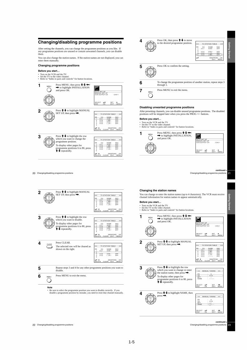
Selecting a languageIf you prefer an on-screen language other than English, use the on-screen display to select another language.
Before you start…• Turn on the VCR and the TV.• Set the TV to the video channel.• Refer to “Index to parts and controls” for button locations.
The abbreviations of the languages are as follows:
1 Press MENU, then press M/m/</, to highlight LANGUAGE SET and press OK.
2 Press M/m/</, to highlight the abbreviation of the desired language from the table below, then press OK.
MENU
OK
PLAY
EXIT MENU:OK:SETSELECT :
GBITESDK
DENLPTFI
FRGRSE
OK
PLAY
Abbreviation Language
GB English
DE German
FR French
IT Italian
NL Dutch
GR Greek
ES Spanish
PT Portuguese
SE Swedish
DK Danish
FI Finnish
Abbreviation Language
Gettin
g S
tarted
17Presetting channels
Presetting channelsIf some channels could not be preset using the Auto Set Up function, you can preset them manually.
Before you start…• Turn on the VCR and the TV.• Set the TV to the video channel.• Refer to “Index to parts and controls” for button locations.
1 Press MENU, then press M/m/</, to highlight INSTALLATION and press OK.
2 Press M/m to highlight MANUAL SET UP, then press ,.
3 Press M/m to highlight the row which you want to preset, then press ,.
To display other pages for programme positions 6 to 80, press M/m repeatedly.
MENU
OK
PLAY
EXITSET
MENU::
OK:ENDSELECT
AUTO SET UPMANUAL SET UP
C H 2 1:VCR OUTPUT CH
:
OK
PLAY
EXIT MENU:CLEAR:DELETESWAPPING OK
TV STATION TABLE
:
54321
0000
3322
2097
ICLA
JDMA
KENB
––––
OFFOFFOFFOFF
PR CH NAME DEC
OK
PLAY
MENU:OK:ENDSELECT
MANUAL TUNING
PR : 5CH : – – –MFT : –NAME : – – – –
: SET :EXIT
continued
Gettin
g S
tarted
19Presetting channels
If the picture is not clearIf the picture is not clear, you may use the Manual Fine Tuning (MFT) function. After step 4, press M/m to select MFT. Press </, to get a clear picture, then press MENU to exit the menu.
Note• When adjusting MFT, the menu may become difficult to read due to interference
from the picture being received.
18 Presetting channels
4 Press </, repeatedly until the channel you want is displayed.
5 Press M/m to highlight NAME, then press ,.
6 Enter the station name.
1 Press M/m to select a character.Each time you press M, the character changes as shown below.A t B t … t Z t 0 t 1 t … t 9 t A
2 Press , to set the next character.The next space is flashed.To correct a character, press </, until the character you want to correct is flashed, then reset it.
You can set up to 4 characters for the station name.
7 Press OK to confirm the station name.
8 Press MENU to exit the menu.
OK
PLAY
MENU:OK:ENDSELECT
MANUAL TUNING
PR : 5CH : 0 3 3MFT : –NAME : – – – –
: SET :EXIT
OK
PLAY
MENU:OK:ENDSELECT
MANUAL TUNING
PR : 5CH : 0 3 3MFT : –NAME : – – – –
: SET :EXIT
OK
PLAY
MENU:OK:ENDSELECT
MANUAL TUNING
PR : 5CH : 0 3 3MFT : –NAME : O– – –
: SET :EXIT
OK
PLAY
MENU
1-5
20 Changing/disabling programme positions
Changing/disabling programme positionsAfter setting the channels, you can change the programme positions as you like. If any programme positions are unused or contain unwanted channels, you can disable them.
You can also change the station names. If the station names are not displayed, you can enter them manually.
Changing programme positions
Before you start…• Turn on the VCR and the TV.• Set the TV to the video channel.• Refer to “Index to parts and controls” for button locations.
1 Press MENU, then press M/m/</, to highlight INSTALLATION and press OK.
2 Press M/m to highlight MANUAL SET UP, then press ,.
3 Press M/m to highlight the row which you want to change the programme position.
To display other pages for programme positions 6 to 80, press M/m repeatedly.
MENU
OK
PLAY
SETMENU:
:OK:END
SELECT
AUTO SET UPMANUAL SET UPVCR OUTPUT CH
:
:
EXIT
C H 2 1
OK
PLAY
CH
MENU:CLEAR:DELETESWAPPING OK
TV STATION TABLE
:
54321
0000
3322
2097
ICLA
JDMA
KENB
––––
OFFOFFOFFOFF
PR NAME DEC
EXIT
OK
PLAY
CH
MENU:CLEAR:DELETESWAPPING OK
TV STATION TABLE
:
54321
0000
3322
2097
ICLA
JDMA
KENB
––––
OFFOFFOFFOFF
PR NAME DEC
EXIT
Gettin
g S
tarted
21Changing/disabling programme positions
Disabling unwanted programme positionsAfter presetting channels, you can disable unused programme positions. The disabled positions will be skipped later when you press the PROG +/– buttons.
Before you start…• Turn on the VCR and the TV.• Set the TV to the video channel.• Refer to “Index to parts and controls” for button locations.
4 Press OK, then press M/m to move to the desired programme position.
5 Press OK to confirm the setting.
6 To change the programme position of another station, repeat steps 3 through 5.
7 Press MENU to exit the menu.
1 Press MENU, then press M/m/</, to highlight INSTALLATION, and press OK.
OK
PLAY
CH
MENU:SWAPPING OK
TV STATION TABLE
:
54321
000
0
233
2
920
7
LIC
A
MJD
A
NKE
B
–––
–
OFFOFFOFF
OFFPR NAME DEC
EXIT
OK
PLAY
MENU
MENU
OK
PLAY
SETMENU:
:OK:END
SELECT
AUTO SET UPMANUAL SET UPVCR OUTPUT CH
:
:
EXIT
C H 2 1
continued
Gettin
g S
tarted
23Changing/disabling programme positions
Changing the station namesYou can change or enter the station names (up to 4 characters). The VCR must receive channel information for station names to appear automatically.
Before you start…• Turn on the VCR and the TV.• Set the TV to the video channel.• Refer to “Index to parts and controls” for button locations.
1 Press MENU, then press M/m/</, to highlight INSTALLATION and press OK.
2 Press M/m to highlight MANUAL SET UP, then press ,.
3 Press M/m to highlight the row which you want to change or enter the station name, then press ,.
To display other pages for programme positions 6 to 80, press M/m repeatedly.
4 Press M/m to highlight NAME, then press ,.
MENU
OK
PLAY
SETMENU:
:OK:END
SELECT
AUTO SET UPMANUAL SET UPVCR OUTPUT CH
:
:
EXIT
C H 2 1
OK
PLAY
CH
MENU:CLEAR:DELETESWAPPING OK
TV STATION TABLE
:
54321
00000
33322
32097
–ICLA
–JDMA
–KENB
–––––
OFFOFFOFFOFFOFF
PR NAME DEC
EXIT
OK
PLAY
MENU:OK:ENDSELECT
MANUAL TUNING
PR : 5CH : 0 3 3MFT : –NAME : – – – –
: SET :EXIT
OK
PLAY
MENU:OK:ENDSELECT
MANUAL TUNING
PR : 5CH : 0 3 3MFT : –NAME : – – – –
: SET :EXIT
continued
22 Changing/disabling programme positions
Note• Be sure to select the programme position you want to disable correctly. If you
disable a programme position by mistake, you need to reset that channel manually.
2 Press M/m to highlight MANUAL SET UP, then press ,.
3 Press M/m to highlight the row which you want to disable.
To display other pages for programme positions 6 to 80, press M/m repeatedly.
4 Press CLEAR.
The selected row will be cleared as shown on the right.
5 Repeat steps 3 and 4 for any other programme positions you want to disable.
6 Press MENU to exit the menu.
OK
PLAY
CH
EXIT MENU:CLEAR:DELETESWAPPING OK
TV STATION TABLE
:
54321
0000
3322
2097
ICLA
JDMA
KENB
––––
OFFOFFOFFOFF
PR NAME DEC
OK
PLAY
MENU:CLEAR:DELETESWAPPING OK
TV STATION TABLE
:
54321
0000
3322
2097
ICLA
JDMA
KENB
––––
OFFOFFOFFOFF
PR CH NAME DEC
EXIT
CLEAR
CH
MENU:CLEAR:DELETESWAPPING OK
TV STATION TABLE
:
54321
00
0
33
2
20
7
IC
A
JD
A
KE
B
––
–
OFFOFF
OFFPR NAME DEC
EXIT
MENU

1-6
24 Changing/disabling programme positions
5 Enter the station name.
1 Press M/m to select a character.Each time you press M, the character changes as shown below.A t B t … t Z t 0 t 1 t … t 9 t A
2 Press , to set the next character.The next space is flashed.To correct a character, press </, until the character you want to correct is flashed, then reset it.
You can set up to 4 characters for the station name.
6 Press OK to confirm the new name.
7 Press MENU to exit the menu.
OK
PLAY
EXIT MENU:OK:ENDSELECT
MANUAL TUNING
PR : 5CH : 0 3 3MFT : –NAME : O– – –
: SET :
OK
PLAY
MENU
Gettin
g S
tarted
25Setting the clock
Setting the clockYou must set the time and date on the VCR to use the timer features properly.
The Auto Clock Set function works only if a station in your area is broadcasting a time signal.
Before you start…• Turn on the VCR and the TV.• Set the TV to the video channel.• Refer to “Index to parts and controls” for button locations.
1 Press MENU, then press M/m/</, to highlight CLOCK SET and press OK.
2 Press M/m to set the hour.
3 Press , to select the minutes and set the minutes by pressing M/m.
MENU
OK
PLAY
SETMENU:
:OK:END
SELECT
1 2 0 1 JAN/0: 2 0MON
0 1/
AUTO CLOCK ON:
:EXIT
OK
PLAY
SETMENU:
:OK:END
SELECT
1 8 0 1 JAN/0: 2 0MON
0 1/
AUTO CLOCK ON:
:EXIT
OK
PLAY
SETMENU:
:OK:END
SELECT
1 8 3 1 JAN/0: 2 0MON
0 1/
AUTO CLOCK ON:
:EXIT
continued
27Playing a tape
Basic O
peratio
ns
Basic Operations
Playing a tapeBefore you start...• Refer to “Index to parts and controls” for button locations.
Additional tasks
To use the time counterPress CLEAR at the point on the tape that you want to find later. The counter in the display window resets to “00:00.” Search for the point afterwards by referring to the counter.
To display the counter on the TV screen, press DISPLAY.
1 Turn on your TV and set it to the video channel.
2 Insert a tape.
The VCR turns on and starts playing automatically if you insert a tape with its safety tab removed.
3 Press H PLAY.
When the tape reaches the end, it will rewind automatically.
To Press
Stop play x STOP
Pause play X PAUSE
Resume play after pause X PAUSE or H PLAY
Fast-forward the tape M FF during stop
Rewind the tape m REW during stop
Eject the tape Z EJECT
OK
PLAY
continued
26 Setting the clock
Tips• If you set AUTO CLOCK to ON, the Auto Clock Set function is activated
whenever the VCR is turned off. The time is adjusted automatically by making reference to the time signal from the station.
• To change the digits while setting, press < to return to the item to be changed, and select the digits by pressing M/m.
4 Set the day, month, and year in sequence by pressing , to select the item to be set, and press M/m to select the digits, then press ,.
The day of the week is set automatically.
5 Press M/m to select ON for the setting the Auto Clock Set function.
The VCR automatically set the clock by the channel between PR01 to PR05 broadcasting the time signal.
If you do not need the Auto Clock Set function, select OFF.
6 Press MENU to exit the menu.
OK
PLAY
SETMENU:
:OK:END
SELECT
1 8 3 82 SEP/0: 2 0FRI
0 1/
AUTO CLOCK ON:
:EXIT
SETMENU:
:OK:END
SELECT
1 8 3 82 SEP/0: 2 0FRI
0 1/
AUTO CLOCK ON:
:EXIT
MENU
1-7
28 Playing a tape
Notes• The counter resets to “00:00” whenever a tape is reinserted.• The counter stops counting when it comes to a portion with no recording.• Depending on your TV, the following may occur while playing an NTSC-recorded
tape:– The picture becomes black and white.– The picture shakes.– No picture appears on the TV screen.– Black streaks appear horizontally on the TV screen.– The colour density increases or decreases.
• While setting the menu on the TV screen, buttons for playback on the remote commander do not function.
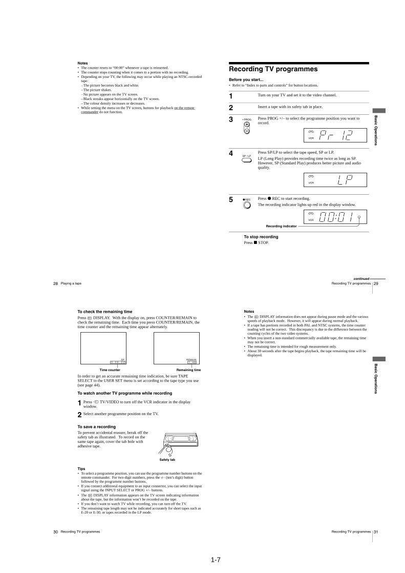
29Recording TV programmes
Basic O
peratio
ns
Recording TV programmesBefore you start...• Refer to “Index to parts and controls” for button locations.
To stop recordingPress x STOP.
1 Turn on your TV and set it to the video channel.
2 Insert a tape with its safety tab in place.
3 Press PROG +/– to select the programme position you want to record.
4 Press SP/LP to select the tape speed, SP or LP.
LP (Long Play) provides recording time twice as long as SP. However, SP (Standard Play) produces better picture and audio quality.
5 Press z REC to start recording.
The recording indicator lights up red in the display window.
• PROG
SP / LP
REC
Recording indicator
continued
31Recording TV programmes
Basic O
peratio
ns
Notes• The DISPLAY information does not appear during pause mode and the various
speeds of playback mode. However, it will appear during normal playback.• If a tape has portions recorded in both PAL and NTSC systems, the time counter
reading will not be correct. This discrepancy is due to the difference between the counting cycles of the two video systems.
• When you insert a non-standard commercially available tape, the remaining time may not be correct.
• The remaining time is intended for rough measurement only.• About 30 seconds after the tape begins playback, the tape remaining time will be
displayed.
30 Recording TV programmes
To check the remaining timePress DISPLAY. With the display on, press COUNTER/REMAIN to check the remaining time. Each time you press COUNTER/REMAIN, the time counter and the remaining time appear alternately.
In order to get an accurate remaining time indication, be sure TAPE SELECT in the USER SET menu is set according to the tape type you use (see page 44).
To watch another TV programme while recording
To save a recordingTo prevent accidental erasure, break off the safety tab as illustrated. To record on the same tape again, cover the tab hole with adhesive tape.
Tips• To select a programme position, you can use the programme number buttons on the
remote commander. For two-digit numbers, press the - (ten’s digit) button followed by the programme number buttons.
• If you connect additional equipment to an input connector, you can select the input signal using the INPUT SELECT or PROG +/– buttons.
• The DISPLAY information appears on the TV screen indicating information about the tape, but the information won’t be recorded on the tape.
• If you don’t want to watch TV while recording, you can turn off the TV.• The remaining tape length may not be indicated accurately for short tapes such as
E-20 or E-30, or tapes recorded in the LP mode.
1 Press t TV/VIDEO to turn off the VCR indicator in the display window.
2 Select another programme position on the TV.
4 61 :REMAIN
2 2000 ::SP
Remaining timeTime counter
Safety tab
1-8
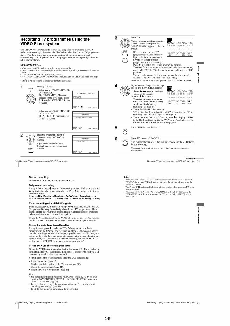
32 Recording TV programmes using the VIDEO Plus+ system
Recording TV programmes using the VIDEO Plus+ systemThe VIDEO Plus+ system is the feature that simplifies programming the VCR to make timer recordings. Just enter the PlusCode number listed in the TV programme guide. The date, times, and programme position of that programme are set automatically. You can preset a total of six programmes, including settings made with other timer methods.
Before you start…• Check that the VCR clock is set to the correct time and date.• Insert a tape with its safety tab in place. Make sure the tape is longer than the total recording
time.• Turn on your TV and set it to the video channel.• Set TIMER METHOD to VIDEOPLUS or VARIABLE in the USER SET menu (see page
45).• Refer to “Index to parts and controls” for button locations.
1 Press TIMER.
• When you set TIMER METHOD to VARIABLE:The TIMER METHOD menu appears on the TV screen. Press M/m to select VIDEOPLUS, then press OK.
• When you set TIMER METHOD to VIDEOPLUS:The VIDEOPLUS menu appears on the TV screen.
2 Press the programme number buttons to enter the PlusCode number.
If you make a mistake, press CLEAR and re-enter the correct number.
TIMER
OK
PLAY
MENU:OK:SETSELECT :
EXIT
TIMER METHOD
STANDARDVIDEOPLUS
MENU:OK:SETCODE 0 – 9:
VIDEOPLUS
CODE – – – – – – – – –
EXIT
1 2 3
4 5 6
7 8 9
0
CLEAR
MENU:OK:SETCODE 0 – 9
1 2 3 4 – – – – –
:
VIDEOPLUS
CODE
EXIT
33Recording TV programmes using the VIDEO Plus+ system
Basic O
peratio
ns
3 Press OK.
The programme position, date, start and stop times, tape speed, and VPS/PDC setting appear on the TV screen.
• If “– –” appears in the “PR” (programme) column (this may happen for local broadcasts), you have to set the appropriate programme position manually.Press M/m to select the desired programme position.To record from another source connected to the input connector, press INPUT SELECT to display the connected line in the “PR” position.You will only have to do this operation once for the referred channel. The VCR will then store your setting.
If the information is incorrect, press CLEAR to cancel the setting.
4 If you want to change the date, tape speed, and the VPS/PDC setting:
1 Press </, to select the item you want to change.
2 Press M/m to reset it.• To record the same programme
every day or the same day every week, see “Daily/weekly recording” on page 34.
• To use the VPS/PDC function, set V/P to ON. For details about the VPS/PDC function, see “Timer recording with VPS/PDC signals” on page 34.
• To use the Auto Tape Speed function, press m to display “AUTO” in the blank positions next to the “V/P” row. For details, see “To use the Auto Tape Speed function” on page 34.
5 Press MENU to exit the menu.
6 Press ?/1 to turn off the VCR.
The indicator appears in the display window and the VCR stands by for recording.
To record from another source, leave the connected equipment switched on.
CLEAR
OK
PLAY
INPUTSELECT
EXITSET
MENU::
OK:ENDSELECT– – – – – – – – – – – – – – ––: :
PR DAY START STOP V/PFRISEP82 / 1 8 : 3 0
3 5 S A 2 9 1 9 0 0 2 0 0 –LP0: :– – – – – – – – – – – – – – ––: :– – – – – – – – – – – – – – ––: :– – – – – – – – – – – – – – ––: :– – – – – – – – – – – – – – ––: :
:
OK
PLAY
EXITSET
MENU::
OK:ENDSELECT– – – – – – – – – – – – – – ––: :
PR DAY START STOP V/PON
FRISEP82 / 1 8 : 3 0
3 5 S A 2 9 1 9 0 0 2 0 0 LP0: :– – – – – – – – – – – – – – ––: :– – – – – – – – – – – – – – ––: :– – – – – – – – – – – – – – ––: :– – – – – – – – – – – – – – ––: :
:
MENU
continued
35Recording TV programmes using the VIDEO Plus+ system
Basic O
peratio
ns
Notes• If the VPS/PDC signal is too weak or the broadcasting station failed to transmit
VPS/PDC signals, the VCR will start recording at the set time without using the VPS/PDC function.
• The and indicators flash in the display window when you press ?/1 with no tape inserted.
• When you set TIMER METHOD to STANDARD in the USER SET menu, the VIDEOPLUS menu does not appear on the TV screen. Select VIDEOPLUS or VARIABLE.
34 Recording TV programmes using the VIDEO Plus+ system
To stop recordingTo stop the VCR while recording, press x STOP.
Daily/weekly recordingIn step 4 above, press m to select the recording pattern. Each time you press m, the indication changes as shown below. Press M to change the indication in reverse order.today t DLY (Monday to Sunday) t W-SAT (every Saturday) ..... t W-SUN (every Sunday) t 1 month later t (dates count down) t today
Timer recording with VPS/PDC signalsSome broadcast systems transmit VPS (Video Programme System) or PDC (Programme Delivery Control) signals with their TV programmes. These signals ensure that your timer recordings are made regardless of broadcast delays, early starts, or broadcast interruptions.
To use the VPS/PDC function, set V/P to ON in step 4 above. You can also use the VPS/PDC function for a source connected to the input connector.
To use the Auto Tape Speed functionIn step 4 above, press m to select AUTO. When you are recording a programme in the SP mode and the remaining tape length becomes shorter than the recording time, the recording tape speed is automatically changed to the LP mode. Note that some noise will appear on the picture when the tape speed is changed. To operate this function correctly, the “TAPE SELECT” setting in the USER SET menu must be accurate. (page 44)
To use the VCR after setting the timerTo use the VCR before a recording begins, just press ?/1. The indicator turns off and the VCR switches on. Remember to press ?/1 to reset the VCR to recording standby after using the VCR.
You can also do the following tasks while the VCR is recording:
• Reset the counter (page 27).• Display tape information on the TV screen (page 30).• Check the timer settings (page 41).• Watch another TV programme (page 30).
Tips• You can set the extended time for the VIDEO Plus+ setting by 10, 20, 30, or 60
minutes. Set VIDEOPLUS+ EXTEND in the EASY OPERATION menu to the desired extended time (page 45).
• To check, change, or cancel the programme setting, see “Checking/changing/cancelling timer settings” (page 41).
• To set the tape speed, you can also use the SP/LP button.
1-9
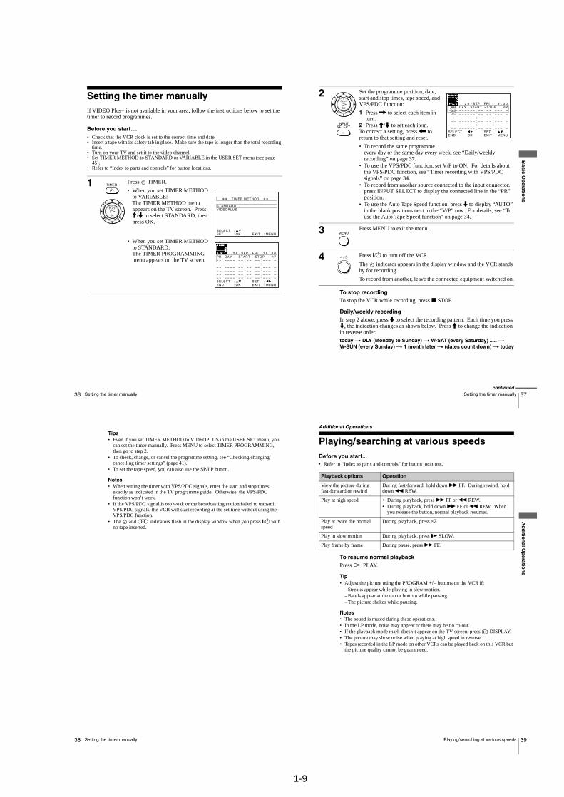
36 Setting the timer manually
Setting the timer manuallyIf VIDEO Plus+ is not available in your area, follow the instructions below to set the timer to record programmes.
Before you start…• Check that the VCR clock is set to the correct time and date.• Insert a tape with its safety tab in place. Make sure the tape is longer than the total recording
time.• Turn on your TV and set it to the video channel.• Set TIMER METHOD to STANDARD or VARIABLE in the USER SET menu (see page
45).• Refer to “Index to parts and controls” for button locations.
1 Press TIMER.
• When you set TIMER METHOD to VARIABLE:The TIMER METHOD menu appears on the TV screen. Press M/m to select STANDARD, then press OK.
• When you set TIMER METHOD to STANDARD:The TIMER PROGRAMMING menu appears on the TV screen.
TIMER
OK
PLAY
EXIT MENU:OK:SETSELECT :
TIMER METHOD
STANDARDVIDEOPLUS
EXITSET
MENU::
OK:ENDSELECT– – – – – – – – – – – – – – ––: :
PR DAY START STOP V/PFRISEP2 8 / 1 8 : 3 0
– – – – – – – – – – – – – – ––: :– – – – – – – – – – – – – – ––: :– – – – – – – – – – – – – – ––: :– – – – – – – – – – – – – – ––: :– – – – – – – – – – – – – – ––: :
:
37Setting the timer manually
Basic O
peratio
ns
To stop recordingTo stop the VCR while recording, press x STOP.
Daily/weekly recordingIn step 2 above, press m to select the recording pattern. Each time you press m, the indication changes as shown below. Press M to change the indication in reverse order.
today t DLY (Monday to Sunday) t W-SAT (every Saturday) ..... t W-SUN (every Sunday) t 1 month later t (dates count down) t today
2 Set the programme position, date, start and stop times, tape speed, and VPS/PDC function:
1 Press , to select each item in turn.
2 Press M/m to set each item.To correct a setting, press < to return to that setting and reset.
• To record the same programme every day or the same day every week, see “Daily/weekly recording” on page 37.
• To use the VPS/PDC function, set V/P to ON. For details about the VPS/PDC function, see “Timer recording with VPS/PDC signals” on page 34.
• To record from another source connected to the input connector, press INPUT SELECT to display the connected line in the “PR” position.
• To use the Auto Tape Speed function, press m to display “AUTO” in the blank positions next to the “V/P” row. For details, see “To use the Auto Tape Speed function” on page 34.
3 Press MENU to exit the menu.
4 Press ?/1 to turn off the VCR.
The indicator appears in the display window and the VCR stands by for recording.
To record from another, leave the connected equipment switched on.
OK
PLAY
INPUTSELECT
EXITSET
MENU::
OK:ENDSELECT
– – – – – – – – – – – – – – ––: :
PR DAY START STOP V/PFRISEP82 / 1 8 : 3 0
3 5 – – – – – – – – – – – – ––: :– – – – – – – – – – – – – – ––: :– – – – – – – – – – – – – – ––: :– – – – – – – – – – – – – – ––: :– – – – – – – – – – – – – – ––: :
:
MENU
continued
39Playing/searching at various speeds
Ad
ditio
nal O
peratio
ns
Additional Operations
Playing/searching at various speedsBefore you start...• Refer to “Index to parts and controls” for button locations.
To resume normal playbackPress H PLAY.
Tip• Adjust the picture using the PROGRAM +/– buttons on the VCR if:
– Streaks appear while playing in slow motion.– Bands appear at the top or bottom while pausing.– The picture shakes while pausing.
Notes• The sound is muted during these operations.• In the LP mode, noise may appear or there may be no colour.• If the playback mode mark doesn’t appear on the TV screen, press DISPLAY.• The picture may show noise when playing at high speed in reverse.• Tapes recorded in the LP mode on other VCRs can be played back on this VCR but
the picture quality cannot be guaranteed.
Playback options Operation
View the picture during fast-forward or rewind
During fast-forward, hold down M FF. During rewind, hold down m REW.
Play at high speed • During playback, press M FF or m REW.• During playback, hold down M FF or m REW. When
you release the button, normal playback resumes.
Play at twice the normal speed
During playback, press ×2.
Play in slow motion During playback, press y SLOW.
Play frame by frame During pause, press M FF.
38 Setting the timer manually
Tips• Even if you set TIMER METHOD to VIDEOPLUS in the USER SET menu, you
can set the timer manually. Press MENU to select TIMER PROGRAMMING, then go to step 2.
• To check, change, or cancel the programme setting, see “Checking/changing/cancelling timer settings” (page 41).
• To set the tape speed, you can also use the SP/LP button.
Notes• When setting the timer with VPS/PDC signals, enter the start and stop times
exactly as indicated in the TV programme guide. Otherwise, the VPS/PDC function won’t work.
• If the VPS/PDC signal is too weak or the broadcasting station failed to transmit VPS/PDC signals, the VCR will start recording at the set time without using the VPS/PDC function.
• The and indicators flash in the display window when you press ?/1 with no tape inserted.

1-10
40 Setting the recording duration time
Setting the recording duration timeAfter you have started recording in the normal way, you can have the VCR stop recording automatically after a specified duration.
Before you start...• Refer to “Index to parts and controls” for button locations.
To extend the durationPress z REC repeatedly to set a new duration time.
To cancel the durationPress z REC repeatedly until the indicator disappears and the VCR returns to the normal recording mode.
To stop recordingTo stop the VCR while recording, press x STOP.
Note• You cannot display the current tape time in the display window when setting the
recording duration time.
1 While recording, press z REC.
The indicator appears in the display window.
2 Press z REC repeatedly to set the duration time.
Each press advances the time in increments of 30 minutes.
The tape counter decreases minute by minute to 0:00, then the VCR stops recording and turns off automatically.
0:30 1:00 4:00 4:30 Normal recording
41Checking/changing/cancelling timer settings
Ad
ditio
nal O
peratio
ns
Checking/changing/cancelling timer settingsBefore you start…• Turn on your TV and set it to the video channel.• Refer to “Index to parts and controls” for button locations.
1 Press ?/1 to turn on the VCR.
2 Press MENU, then press M/m to highlight TIMER PROGRAMMING and press OK.
• If you want to change or cancel a setting, go on to the next step.
• If you do not need to change or cancel the settings, press MENU, then turn off the VCR to return to recording standby.
3 Press M/m to select the setting you want to change or cancel, then press ,.
The PR number on the selected row flashes.
4 • To change the setting, press </, to select the item you want to change, then press M/m to reset it.
• To cancel the setting, press CLEAR.
5 Press MENU to exit the menu.
If any settings remain, turn off the VCR to return to recording standby.
SETMENU:
:OK:END
SELECT– – – – – – – – – – – – – – ––: :
PR DAY START STOP V/PFRISEP82 / 1 8 : 3 0
3 5 S A 1 9 0 0 2 0 0 –0: :2 9 S A
2 92 9 2 1 0 0 2 3 0 –1: :
3 0 S A 6 1 2 0 0 1 3 0 –3: :– – – – – – – – – – – – – – ––: :– – – – – – – – – – – – – – ––: :
:EXIT
LPLPSP
2 92 9
6
LPLPSP
EXITSET
MENU::
OK:ENDSELECT– – – – – – – – – – – – – – ––: :
PR DAY START STOP V/PFRISEP82 / 1 8 : 3 0
3 5 S A 1 9 0 0 2 0 0 –0: :2 9 S A 2 1 0 0 2 3 0 –1: :3 0 S A 1 2 0 0 1 3 0 –3: :– – – – – – – – – – – – – – ––: :– – – – – – – – – – – – – – ––: :
:
continued
43Adjusting the picture
Ad
ditio
nal O
peratio
ns
Adjusting the pictureAdjusting the trackingAlthough the VCR automatically adjusts the tracking when playing a tape, distortion may occur if the recording is in poor condition. In this case, manually adjust the tracking.
During playback, press PROGRAM +/– on the VCR to display the tracking meter. The distortion should disappear as you press one of the two buttons. To resume automatic tracking adjustments, eject the tape and re-insert it.
Adjusting the picture sharpnessYou can manually adjust the sharpness of the picture.
1 During playback, press MENU, then press M/m/</, to highlight USER SET and press OK.
2 Press M/m to highlight PICTURE, then press ,.
3 Press </, to adjust the sharpness.
To soften the picture, press <.
To sharpen the picture, press ,.
4 Press MENU to exit the menu.
TRACKING – – – – – – – – – – – –
Tracking meter
SETMENU:
:OK:END
SELECT
PICTURE : 90OSD ON:
OFF:
TAPE SELECT E 1 8 0:COLOUR SYSTEM AUTO:TIMER METHODECO. MODE
VARIABLE:
:EXIT
SETMENU:
:OK:
SOFTEN SHARPEN– – – – – –– – –– – – – – – – – – – – –
PICTURE
END EXIT
42 Checking/changing/cancelling timer settings
When the timer settings overlapThe programme that starts first has priority and the second programme starts recording only after the first programme has finished. If the programmes start at the same time, the programme listed first in the menu has priority.
about 20 seconds
will be cut off
Programme 1
Programme 2
about 20 seconds will be cut off
Programme 1
Programme 2
1-11
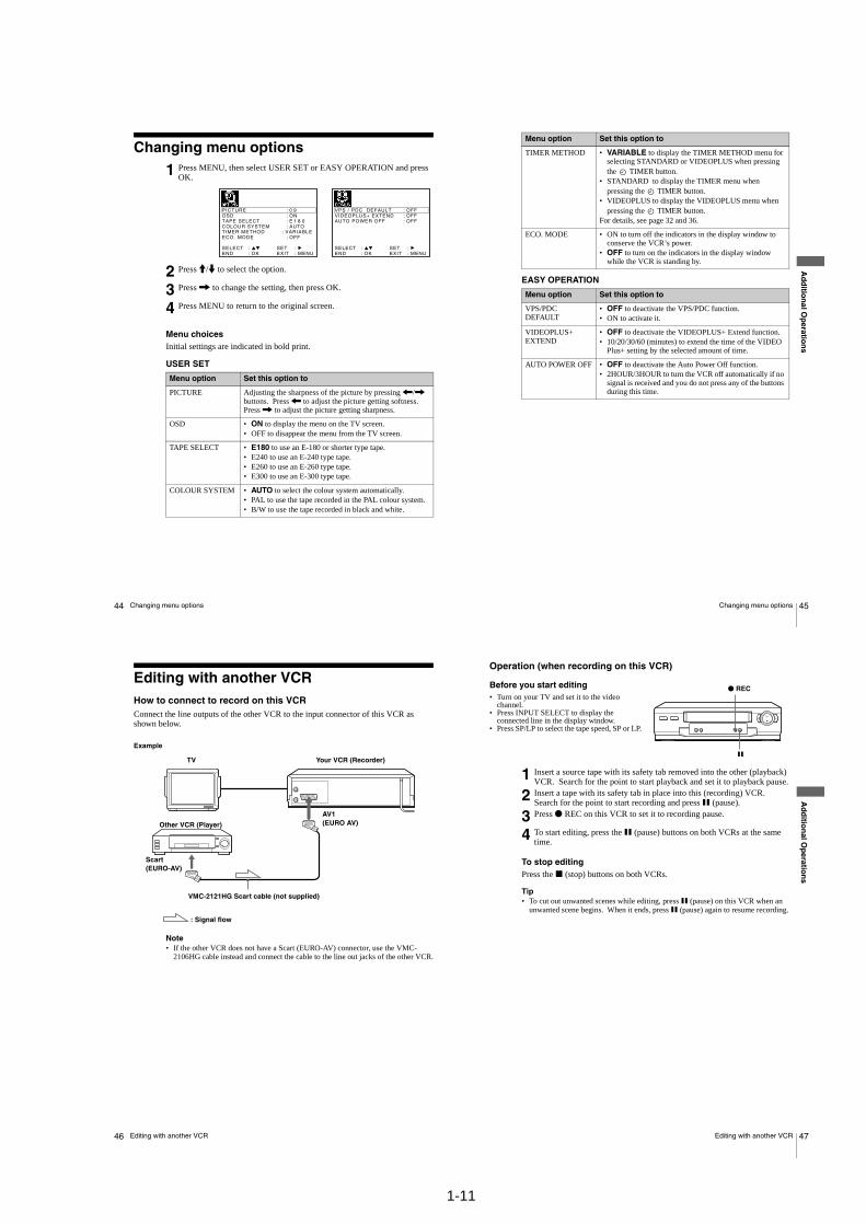
44 Changing menu options
Changing menu options
Menu choicesInitial settings are indicated in bold print.
USER SET
1 Press MENU, then select USER SET or EASY OPERATION and press OK.
2 Press M/m to select the option.
3 Press , to change the setting, then press OK.
4 Press MENU to return to the original screen.
Menu option Set this option to
PICTURE Adjusting the sharpness of the picture by pressing </, buttons. Press < to adjust the picture getting softness. Press , to adjust the picture getting sharpness.
OSD • ON to display the menu on the TV screen.• OFF to disappear the menu from the TV screen.
TAPE SELECT • E180 to use an E-180 or shorter type tape.• E240 to use an E-240 type tape.• E260 to use an E-260 type tape.• E300 to use an E-300 type tape.
COLOUR SYSTEM • AUTO to select the colour system automatically.• PAL to use the tape recorded in the PAL colour system.• B/W to use the tape recorded in black and white.
SETMENU:
:OK:END
SELECT
PICTURE : 90OSD ON:
OFF:
TAPE SELECT E 1 8 0:COLOUR SYSTEM AUTO:TIMER METHODECO. MODE
VARIABLE:
:EXIT EXIT
SETMENU:
:OK:END
SELECT
VPS / PDC DEFAULTVIDEOPLUS+ EXTEND
OFF:
AUTO POWER OFFOFF:OFF:
:
45Changing menu options
Ad
ditio
nal O
peratio
ns
EASY OPERATION
TIMER METHOD • VARIABLE to display the TIMER METHOD menu for selecting STANDARD or VIDEOPLUS when pressing the TIMER button.
• STANDARD to display the TIMER menu when pressing the TIMER button.
• VIDEOPLUS to display the VIDEOPLUS menu when pressing the TIMER button.
For details, see page 32 and 36.
ECO. MODE • ON to turn off the indicators in the display window to conserve the VCR’s power.
• OFF to turn on the indicators in the display window while the VCR is standing by.
Menu option Set this option to
VPS/PDC DEFAULT
• OFF to deactivate the VPS/PDC function.• ON to activate it.
VIDEOPLUS+ EXTEND
• OFF to deactivate the VIDEOPLUS+ Extend function.• 10/20/30/60 (minutes) to extend the time of the VIDEO
Plus+ setting by the selected amount of time.
AUTO POWER OFF • OFF to deactivate the Auto Power Off function.• 2HOUR/3HOUR to turn the VCR off automatically if no
signal is received and you do not press any of the buttons during this time.
Menu option Set this option to
47Editing with another VCR
Ad
ditio
nal O
peratio
ns
Operation (when recording on this VCR)
Before you start editing• Turn on your TV and set it to the video
channel.• Press INPUT SELECT to display the
connected line in the display window.• Press SP/LP to select the tape speed, SP or LP.
To stop editingPress the x (stop) buttons on both VCRs.
Tip• To cut out unwanted scenes while editing, press X (pause) on this VCR when an
unwanted scene begins. When it ends, press X (pause) again to resume recording.
1 Insert a source tape with its safety tab removed into the other (playback) VCR. Search for the point to start playback and set it to playback pause.
2 Insert a tape with its safety tab in place into this (recording) VCR. Search for the point to start recording and press X (pause).
3 Press z REC on this VCR to set it to recording pause.
4 To start editing, press the X (pause) buttons on both VCRs at the same time.
X
z REC
46 Editing with another VCR
Editing with another VCRHow to connect to record on this VCRConnect the line outputs of the other VCR to the input connector of this VCR as shown below.
Example
Note• If the other VCR does not have a Scart (EURO-AV) connector, use the VMC-
2106HG cable instead and connect the cable to the line out jacks of the other VCR.
TV
VMC-2121HG Scart cable (not supplied)
Scart (EURO-AV)
: Signal flow
Your VCR (Recorder)
Other VCR (Player)
AV1 (EURO AV)
1-12E
48 Troubleshooting
Additional Information
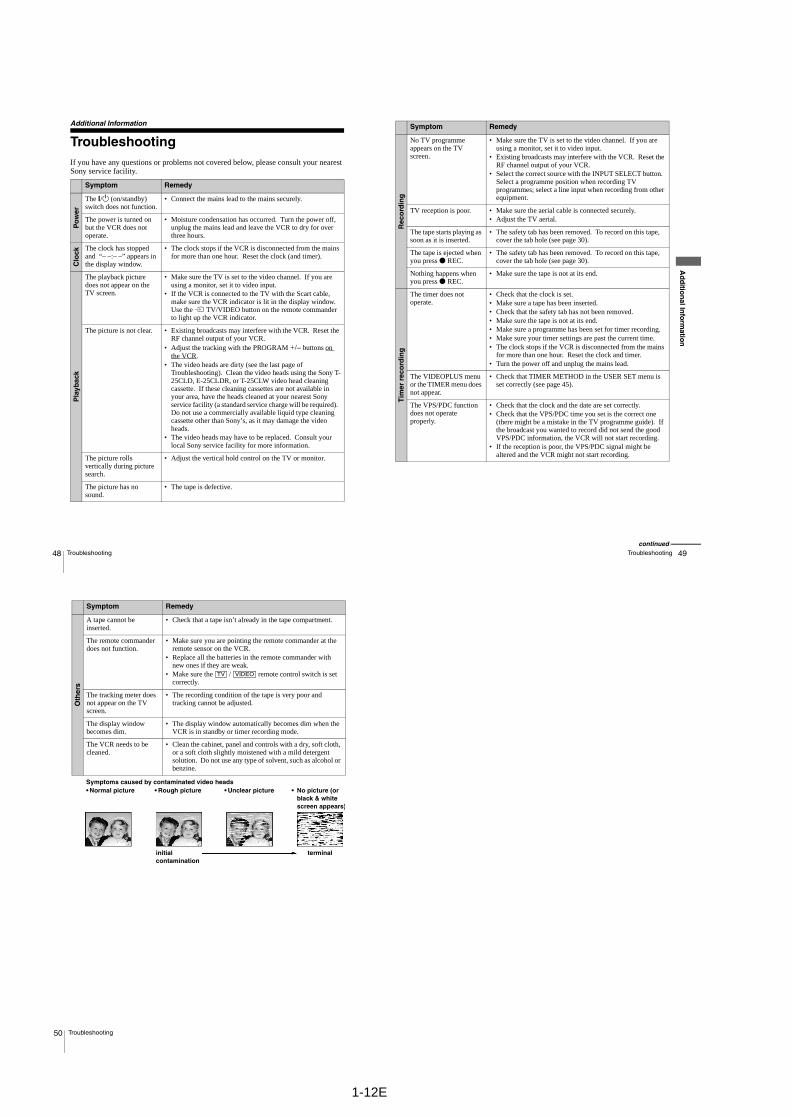
TroubleshootingIf you have any questions or problems not covered below, please consult your nearest Sony service facility.
Symptom Remedy
Po
wer
The ?/1 (on/standby) switch does not function.
• Connect the mains lead to the mains securely.
The power is turned on but the VCR does not operate.
• Moisture condensation has occurred. Turn the power off, unplug the mains lead and leave the VCR to dry for over three hours.
Clo
ck
The clock has stopped and “– –:– –” appears in the display window.
• The clock stops if the VCR is disconnected from the mains for more than one hour. Reset the clock (and timer).
Pla
ybac
k
The playback picture does not appear on the TV screen.
• Make sure the TV is set to the video channel. If you are using a monitor, set it to video input.
• If the VCR is connected to the TV with the Scart cable, make sure the VCR indicator is lit in the display window. Use the t TV/VIDEO button on the remote commander to light up the VCR indicator.
The picture is not clear. • Existing broadcasts may interfere with the VCR. Reset the RF channel output of your VCR.
• Adjust the tracking with the PROGRAM +/– buttons on the VCR.
• The video heads are dirty (see the last page of Troubleshooting). Clean the video heads using the Sony T-25CLD, E-25CLDR, or T-25CLW video head cleaning cassette. If these cleaning cassettes are not available in your area, have the heads cleaned at your nearest Sony service facility (a standard service charge will be required). Do not use a commercially available liquid type cleaning cassette other than Sony’s, as it may damage the video heads.
• The video heads may have to be replaced. Consult your local Sony service facility for more information.
The picture rolls vertically during picture search.
• Adjust the vertical hold control on the TV or monitor.
The picture has no sound.
• The tape is defective.
49Troubleshooting
Ad
ditio
nal In
form
ation
Rec
ord
ing
No TV programme appears on the TV screen.
• Make sure the TV is set to the video channel. If you are using a monitor, set it to video input.
• Existing broadcasts may interfere with the VCR. Reset the RF channel output of your VCR.
• Select the correct source with the INPUT SELECT button. Select a programme position when recording TV programmes; select a line input when recording from other equipment.
TV reception is poor. • Make sure the aerial cable is connected securely.• Adjust the TV aerial.
The tape starts playing as soon as it is inserted.
• The safety tab has been removed. To record on this tape, cover the tab hole (see page 30).
The tape is ejected when you press z REC.
• The safety tab has been removed. To record on this tape, cover the tab hole (see page 30).
Nothing happens when you press z REC.
• Make sure the tape is not at its end.
Tim
er r
eco
rdin
g
The timer does not operate.
• Check that the clock is set.• Make sure a tape has been inserted.• Check that the safety tab has not been removed.• Make sure the tape is not at its end.• Make sure a programme has been set for timer recording.• Make sure your timer settings are past the current time.• The clock stops if the VCR is disconnected from the mains
for more than one hour. Reset the clock and timer.• Turn the power off and unplug the mains lead.
The VIDEOPLUS menu or the TIMER menu does not appear.
• Check that TIMER METHOD in the USER SET menu is set correctly (see page 45).
The VPS/PDC function does not operate properly.
• Check that the clock and the date are set correctly.• Check that the VPS/PDC time you set is the correct one
(there might be a mistake in the TV programme guide). If the broadcast you wanted to record did not send the good VPS/PDC information, the VCR will not start recording.
• If the reception is poor, the VPS/PDC signal might be altered and the VCR might not start recording.
Symptom Remedy
continued
50 Troubleshooting
Oth
ers
A tape cannot be inserted.
• Check that a tape isn’t already in the tape compartment.
The remote commander does not function.
• Make sure you are pointing the remote commander at the remote sensor on the VCR.
• Replace all the batteries in the remote commander with new ones if they are weak.
• Make sure the [TV] / [VIDEO] remote control switch is set correctly.
The tracking meter does not appear on the TV screen.
• The recording condition of the tape is very poor and tracking cannot be adjusted.
The display window becomes dim.
• The display window automatically becomes dim when the VCR is in standby or timer recording mode.
The VCR needs to be cleaned.
• Clean the cabinet, panel and controls with a dry, soft cloth, or a soft cloth slightly moistened with a mild detergent solution. Do not use any type of solvent, such as alcohol or benzine.
Symptom Remedy
Symptoms caused by contaminated video heads• Normal picture • Rough picture
initial contamination
• Unclear picture • No picture (or black & white screen appears)
terminal
2-1
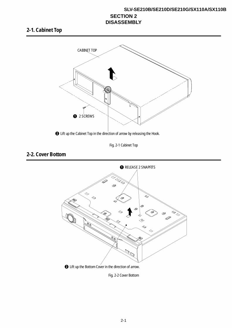
SECTION 2DISASSEMBLY
SLV-SE210B/SE210D/SE210G/SX110A/SX110B
2-1. Cabinet Top
CABINET TOP
´ Lift up the Cabinet Top in the direction of arrow by releasing the Hook.
Π2 SCREWS
Fig. 2-1 Cabinet Top
2-2. Cover Bottom
Fig. 2-2 Cover Bottom
ΠRELEASE 2 SNAPFITS
´ Lift up the Bottom Cover in the direction of arrow.
2-2
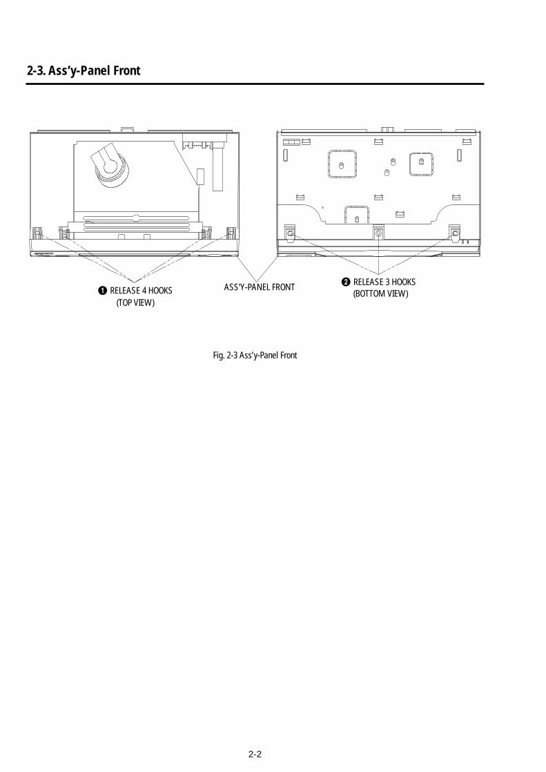
2-3. Ass’y-Panel Front
Fig. 2-3 Ass’y-Panel Front
Œ RELEASE 4 HOOKS´ RELEASE 3 HOOKS
(TOP VIEW)
ASS'Y-PANEL FRONT (BOTTOM VIEW)

2-4. Ass’y MAIN-PCB, DECK
Fig. 2-4 Ass’y Main-PCB, Deck
Π2 SCREWS
´ BRACKET-FRAME
” ASS'Y MAIN-PCB
¨ FLAT CABLE
’ ASS'Y-DECK
ˆ FLAT CABLE
Ø CONNECTOR
∏ RELEASE HOOK
ˇ 3 SCREWS
PUSH
2-5. Internal Views
CYLINDER Assembly (Drum)1-763-706-11 (SE210B/SE210D/SX110A/SX110B)1-763-707-11 (SE210G)
ACE HEAD Assembly1-500-698-11
LOADING MOTOR Assembly1-763-704-11
CAPSTAN MOTOR1-763-703-11
2-3 2-4E
— Top View —
— Bottom View —
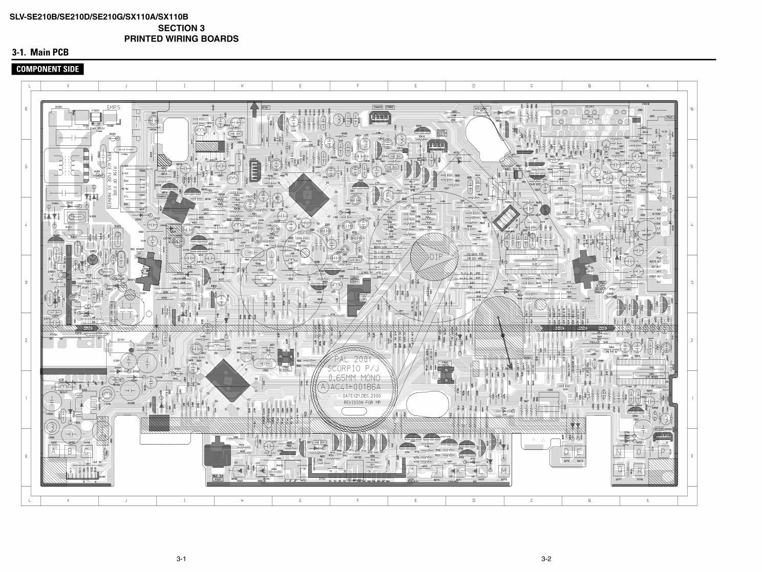
SLV-SE210B/SE210D/SE210G/SX110A/SX110BSECTION 3
PRINTED WIRING BOARDS
3-1 3-2
3-1. Main PCB
COMPONENT SIDE
SLV-SE210B/SE210D/SE210G/SX110A/SX110B
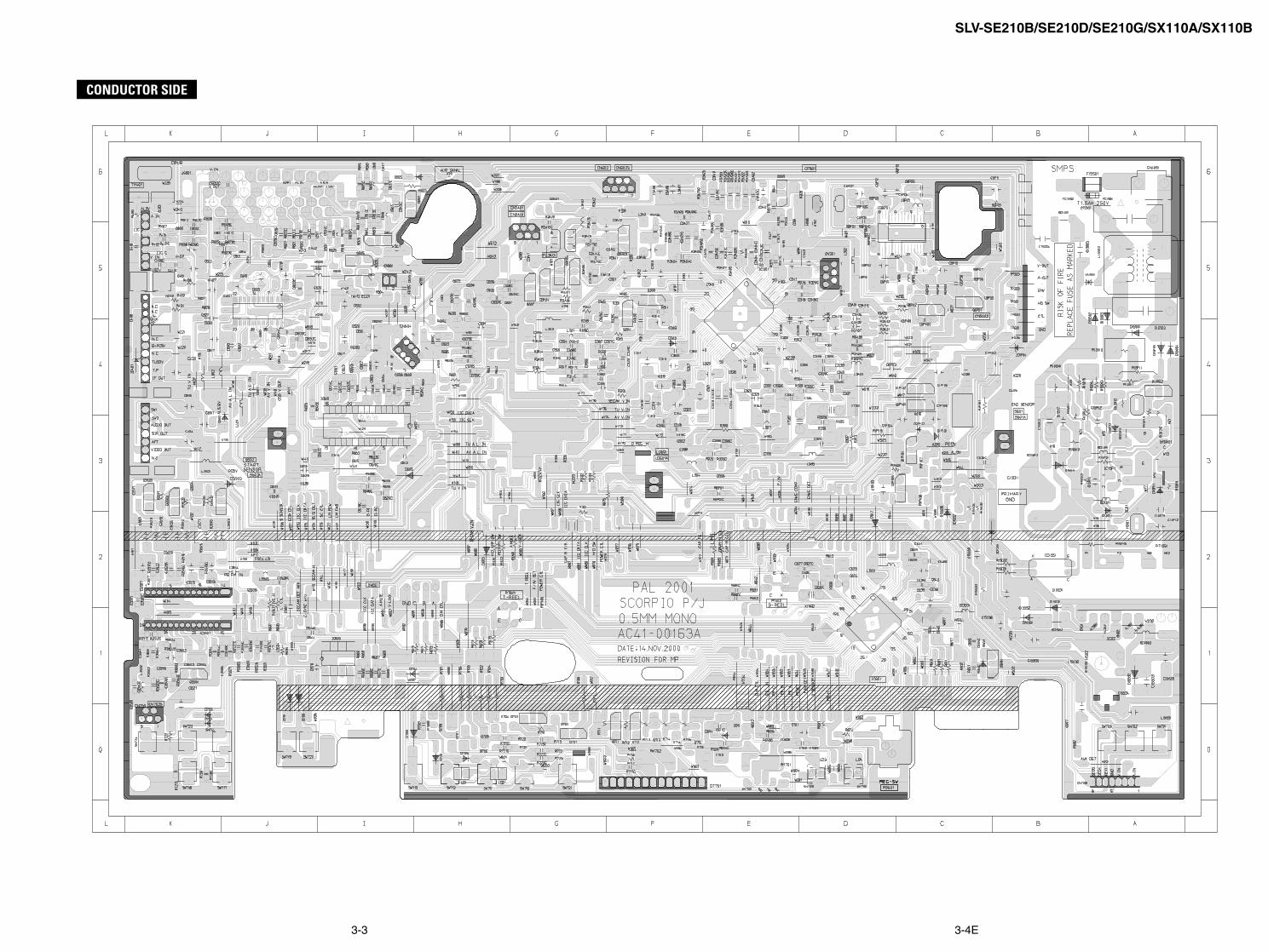
CONDUCTOR SIDE
3-3 3-4E
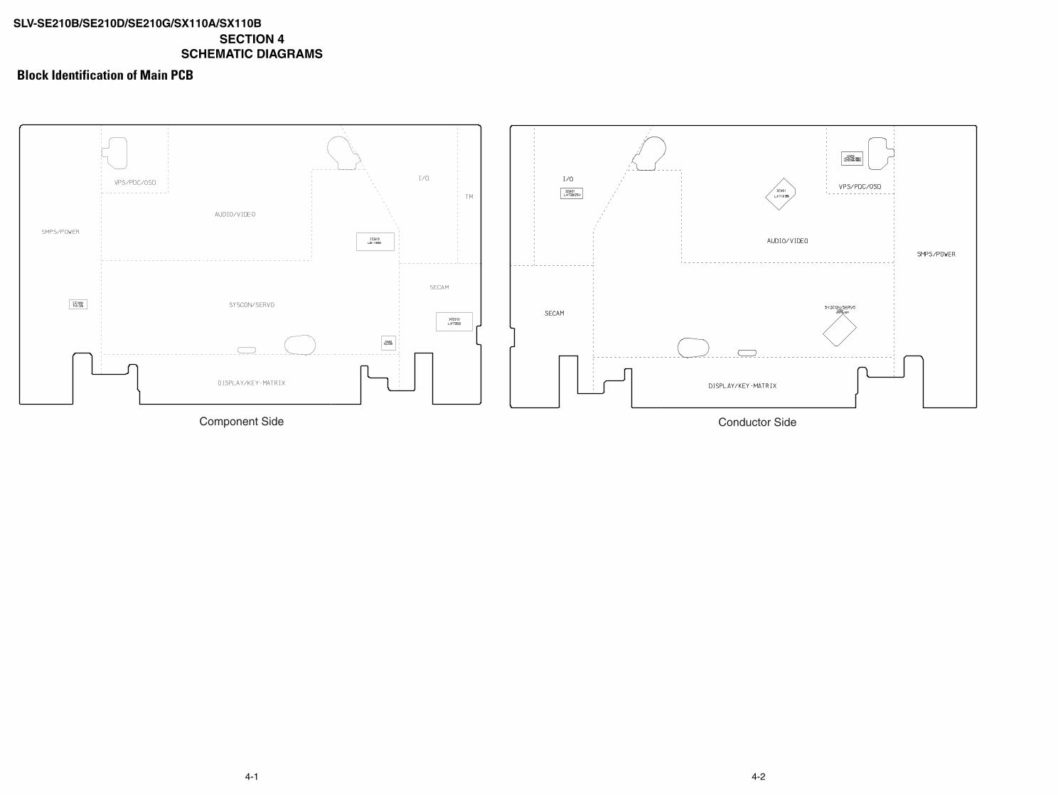
SLV-SE210B/SE210D/SE210G/SX110A/SX110BSECTION 4
SCHEMATIC DIAGRAMS
Block Identification of Main PCB
Component Side Conductor Side
4-1 4-2
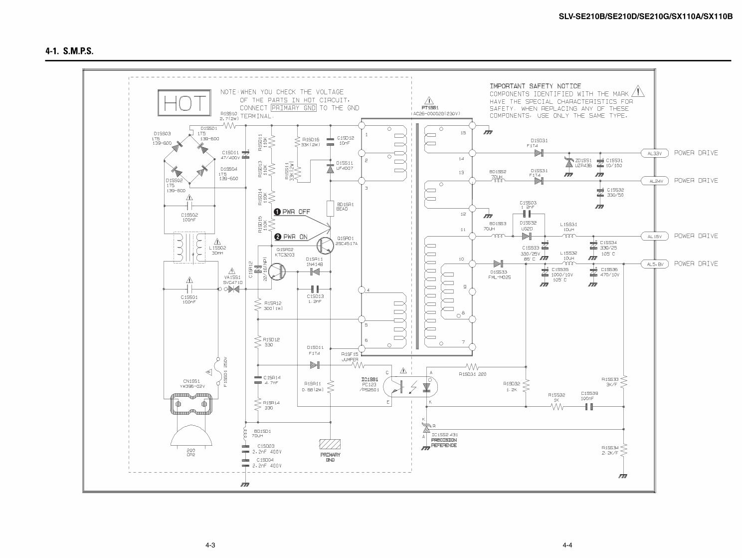
SLV-SE210B/SE210D/SE210G/SX110A/SX110B
4-1. S.M.P.S.
Œ
´
4-3 4-4

SLV-SE210B/SE210D/SE210G/SX110A/SX110B
4-2. Power
4-5 4-6
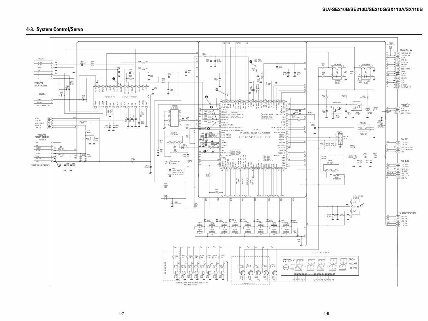
SLV-SE210B/SE210D/SE210G/SX110A/SX110B
4-3. System Control/Servo
∏
˝
ˇ
¨
ˆ
’
”
4-7 4-8

SLV-SE210B/SE210D/SE210G/SX110A/SX110B
Æ
Ú
Ò
Ô
ı
˜
¯
4-4. Audio/Video
4-9 4-10

SLV-SE210B/SE210D/SE210G/SX110A/SX110B
˘
4-5. TM-Block
4-11 4-12
SLV-SE210B/SE210D/SE210G/SX110A/SX110B
¿
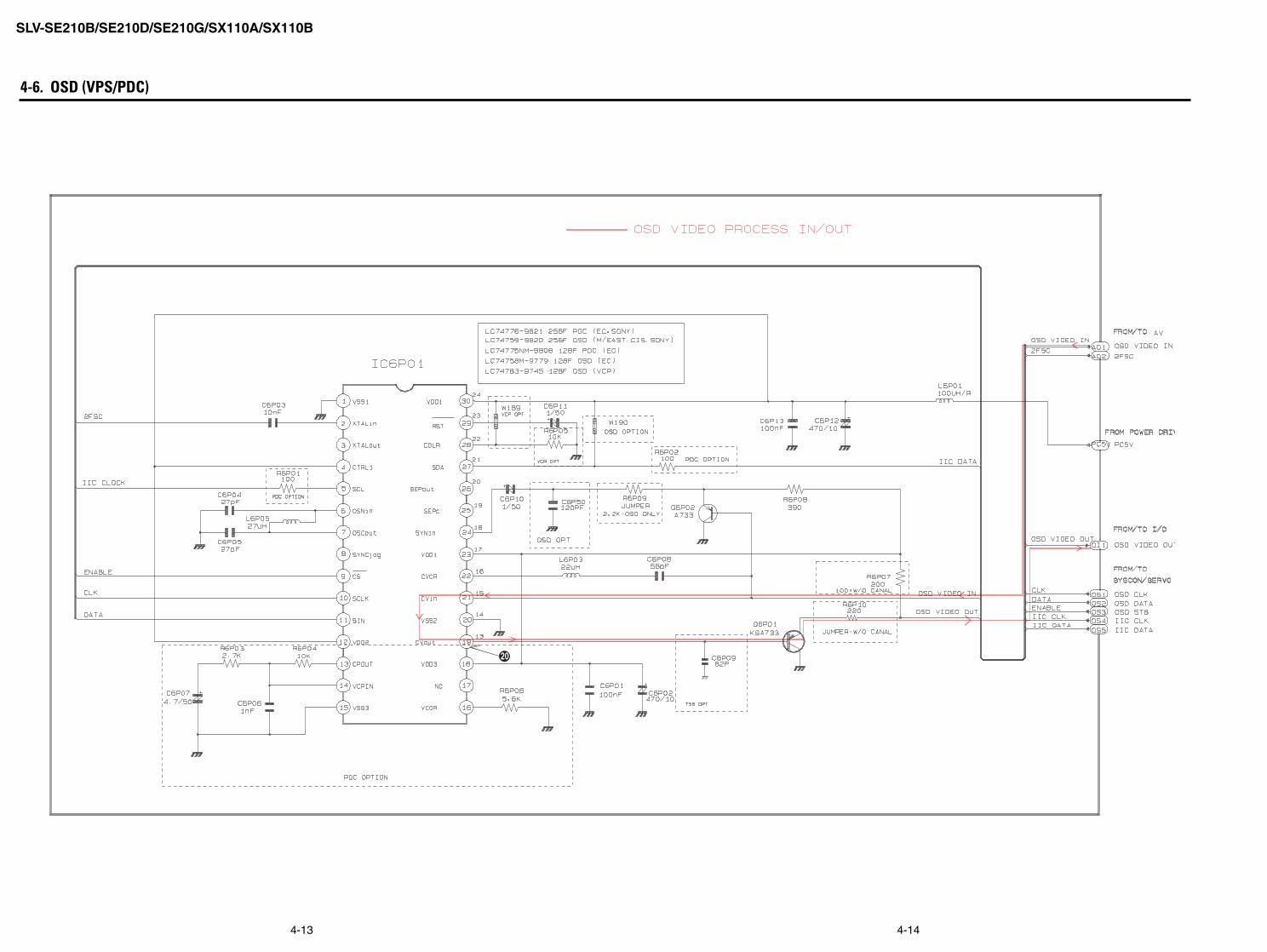
4-6. OSD (VPS/PDC)
4-13 4-14

SLV-SE210B/SE210D/SE210G/SX110A/SX110B
4-7. SECAM (SLV-SE210B/SX110B model)
4-15 4-16
SLV-SE210B/SE210D/SE210G/SX110A/SX110B
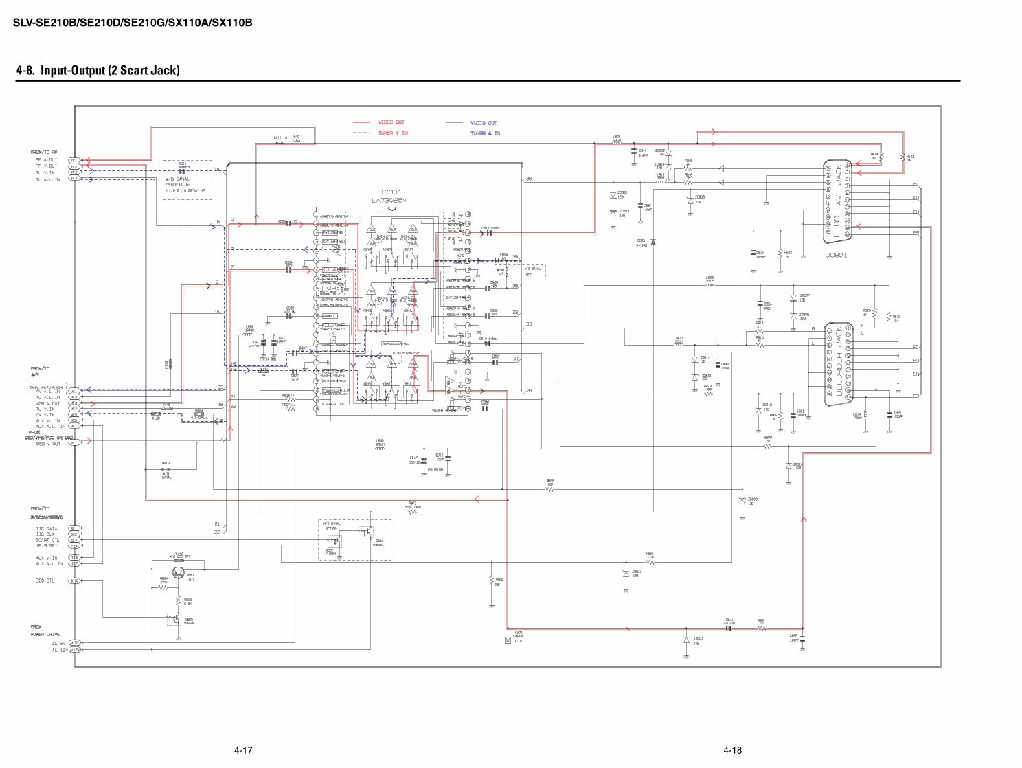
4-8. Input-Output (2 Scart Jack)
4-17 4-18
SLV-SE210B/SE210D/SE210G/SX110A/SX110B
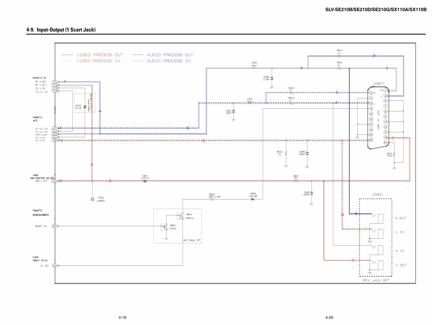
4-9. Input-Output (1 Scart Jack)
4-19 4-20
SLV-SE210B/SE210D/SE210G/SX110A/SX110B
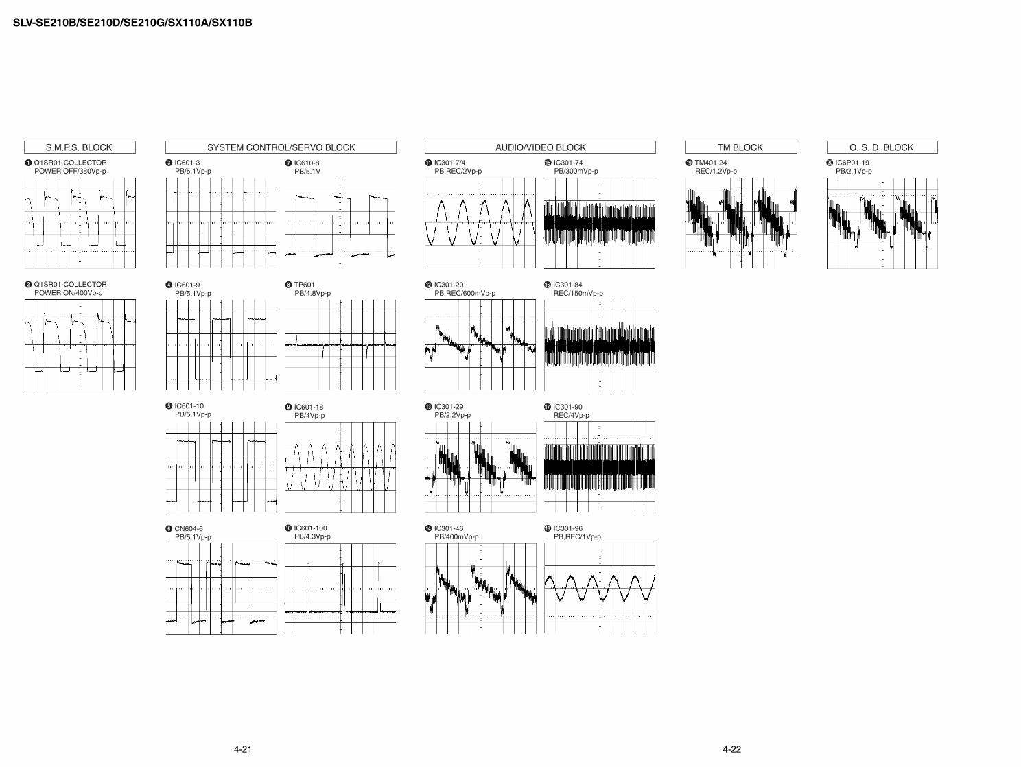
ΠQ1SR01-COLLECTOR POWER OFF/380Vp-p
ˇ IC601-3 PB/5.1Vp-p
” TP601 PB/4.8Vp-p
Ô IC301-7/4 PB,REC/2Vp-p
ı IC301-84 REC/150mVp-p
¿ IC6P01-19 PB/2.1Vp-p
˘ TM401-24 REC/1.2Vp-p
IC301-20 PB,REC/600mVp-p
˜ IC301-90 REC/4Vp-p
Ò IC301-29 PB/2.2Vp-p
Ú IC301-46 PB/400mVp-p
¯ IC301-96 PB,REC/1Vp-p
Æ IC301-74 PB/300mVp-p
¨ IC601-9 PB/5.1Vp-p
’ IC601-18 PB/4Vp-p
ˆ IC601-10 PB/5.1Vp-p
˝ IC601-100 PB/4.3Vp-p
Ø CN604-6 PB/5.1Vp-p
∏ IC610-8 PB/5.1V
´ Q1SR01-COLLECTOR POWER ON/400Vp-p
S.M.P.S. BLOCK TM BLOCK O. S. D. BLOCKSYSTEM CONTROL/SERVO BLOCK AUDIO/VIDEO BLOCK
4-21 4-22

SLV-SE210B/SE210D/SE210G/SX110A/SX110B
4-23 4-24E
SLV-SE210B/SE210D/SE210G/SX110A/SX110BSECTION 5
ALIGNMENT AND ADJUSTMENT
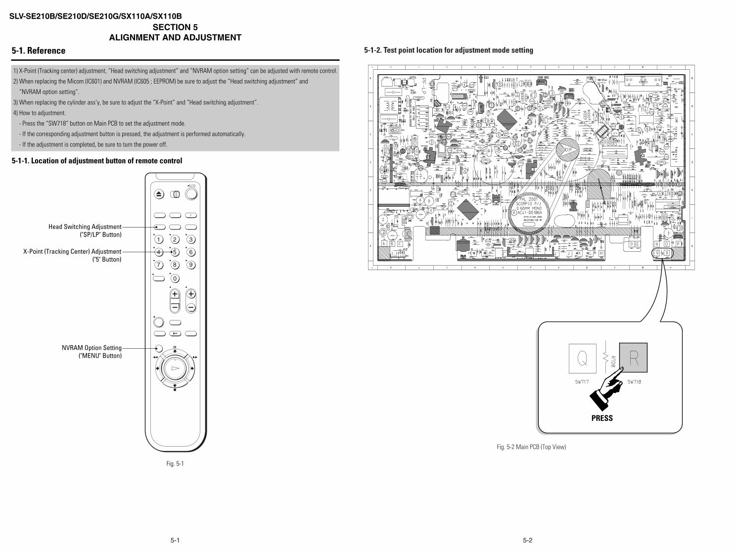
5-1. Reference
1) X-Point (Tracking center) adjustment, “Head switching adjustment” and “NVRAM option setting” can be adjusted with remote control.
2) When replacing the Micom (IC601) and NVRAM (IC605 ; EEPROM) be sure to adjust the “Head switching adjustment” and
“NVRAM option setting”.
3) When replacing the cylinder ass’y, be sure to adjust the “X-Point” and “Head switching adjustment”.
4) How to adjustment.
- Press the “SW718” button on Main PCB to set the adjustment mode.
- If the corresponding adjustment button is pressed, the adjustment is performed automatically.
- If the adjustment is completed, be sure to turn the power off.
5-1-1. Location of adjustment button of remote control
Fig. 5-1
1 2 3
4 5 6
7 8 9
0
X-Point (Tracking Center) Adjustment("5" Button)
Head Switching Adjustment("SP/LP" Button)
NVRAM Option Setting("MENU" Button)
5-1-2. Test point location for adjustment mode setting
Fig. 5-2 Main PCB (Top View)
PRESS
5-1 5-2
5-3
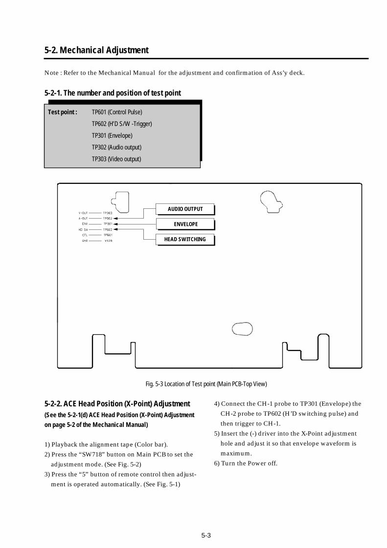
5-2. Mechanical Adjustment
Note : Refer to the Mechanical Manual for the adjustment and confirmation of Ass’y deck.
5-2-1. The number and position of test point
Test point : TP601 (Control Pulse)
TP602 (H’D S/W -Trigger)
TP301 (Envelope)
TP302 (Audio output)
TP303 (Video output)
Fig. 5-3 Location of Test point (Main PCB-Top View)
AUDIO OUTPUT
HEAD SWITCHING
ENVELOPE
5-2-2. ACE Head Position (X-Point) Adjustment(See the 5-2-1(d) ACE Head Position (X-Point) Adjustmenton page 5-2 of the Mechanical Manual)
1) Playback the alignment tape (Color bar).
2) Press the “SW718” button on Main PCB to set the
adjustment mode. (See Fig. 5-2)
3) Press the “5” button of remote control then adjust-
ment is operated automatically. (See Fig. 5-1)
4) Connect the CH-1 probe to TP301 (Envelope) the
CH-2 probe to TP602 (H’D switching pulse) and
then trigger to CH-1.
5) Insert the (-) driver into the X-Point adjustment
hole and adjust it so that envelope waveform is
maximum.
6) Turn the Power off.

5-4E
5-3. Head Switching Point Adjustment
1) Playback the alignment tape.
2) Press the “SW718” button on Main PCB to set the adjustment mode. (See Fig. 5-2 )
3) Press the “SP/LP” button of remote control then adjustment is operated automatically. (See Fig. 5-1)
4) Turn the Power off.
5-4. NVRAM Option Setting
1) Press the “SW718” button on Main PCB to set the adjustment mode. (See Fig. 5-2 )
2) Press the “MENU” button on the remote control about 5 seconds then option setting display is appeared.
(See Fig. 5-4 and 5-5)
3) Select the option number (See Table 5-1) of corresponding model with “FF/REW/STOP/PAUSE” button on
the remote control.
4) If selecting the option number is completed, press the “OK (PALY)” button of remote control.
(If “OK (PLAY)” button is pressed, the selected number is changes reversed color. ; See Fig. 5-4)
5) Press the “MENU” button of remote control again to store the option number.
(“PLEASE WAIT” is displayed for a second as shown Fig. 5-5 and this setting is completed.)
6) Turn the Power off.
1) NVRAM Option is adjusted at production line basically.
2) In case Micom (IC601) and NVRAM (IC605 ; EEPROM) is replaced, be sure to set the corresponding option number of the reqaired
model. (If the option is not set, the unit is not operated.)
01 02 03 04 05 06 07 0809 10 11 12 13 14 15 1617 18 19 20 21 22 23 2425 26 27 28 29 30 31 3233 34 35 36 37 38 39 4041 42 43 44 45 46 47 4849 50 51 52 53 54 55 5657 58 59 60 61 62 63 6465 66 67 68 69 70 71 72
CNG:OK SAVE:MENU
Fig. 5-4
01 02 03 04 05 06 07 0809 10 11 12 13 14 15 1617 18 19 20 21 22 23 2425 26 27 28 29 30 31 3233 34 35 36 37 38 39 4041 42 43 44 45 46 47 4849 50 51 52 53 54 55 5657 58 59 60 61 62 63 6465 66 67 68 69 70 71 72
PLEASE WAIT
Fig. 5-5
<Table 5-1>
MODELS OPTION NUMBER
SLV-SE210/D1SLV-SE210/D2 2, 4, 5, 11, 13, 20, 30, 32, 38, 42, 45, 60, 61, 66SLV-SE210/D3SLV-SX110/A1SLV-SX110/A2 13, 20, 30, 32, 38, 42, 45, 60, 61, 66SLV-SX110/A3SLV-SE210/B 2, 4, 5, 11, 13, 20, 21, 26, 30, 32, 33, 34, 35, 36, 38, 45, 60, 61, 66SLV-SX110/B 13, 20, 21, 26, 30, 32, 33, 34, 35, 36, 38, 45, 60, 61, 66SLV-SE210/G 3, 4, 5, 10, 13, 27, 30, 32, 36, 38, 41, 45, 60, 61, 66SLV-SX110/K 13, 20, 30, 32, 35, 38, 42, 45, 60, 61, 66
6-1
SECTION 6REPAIR PARTS LIST
SLV-SE210B/SE210D/SE210G/SX110A/SX110B
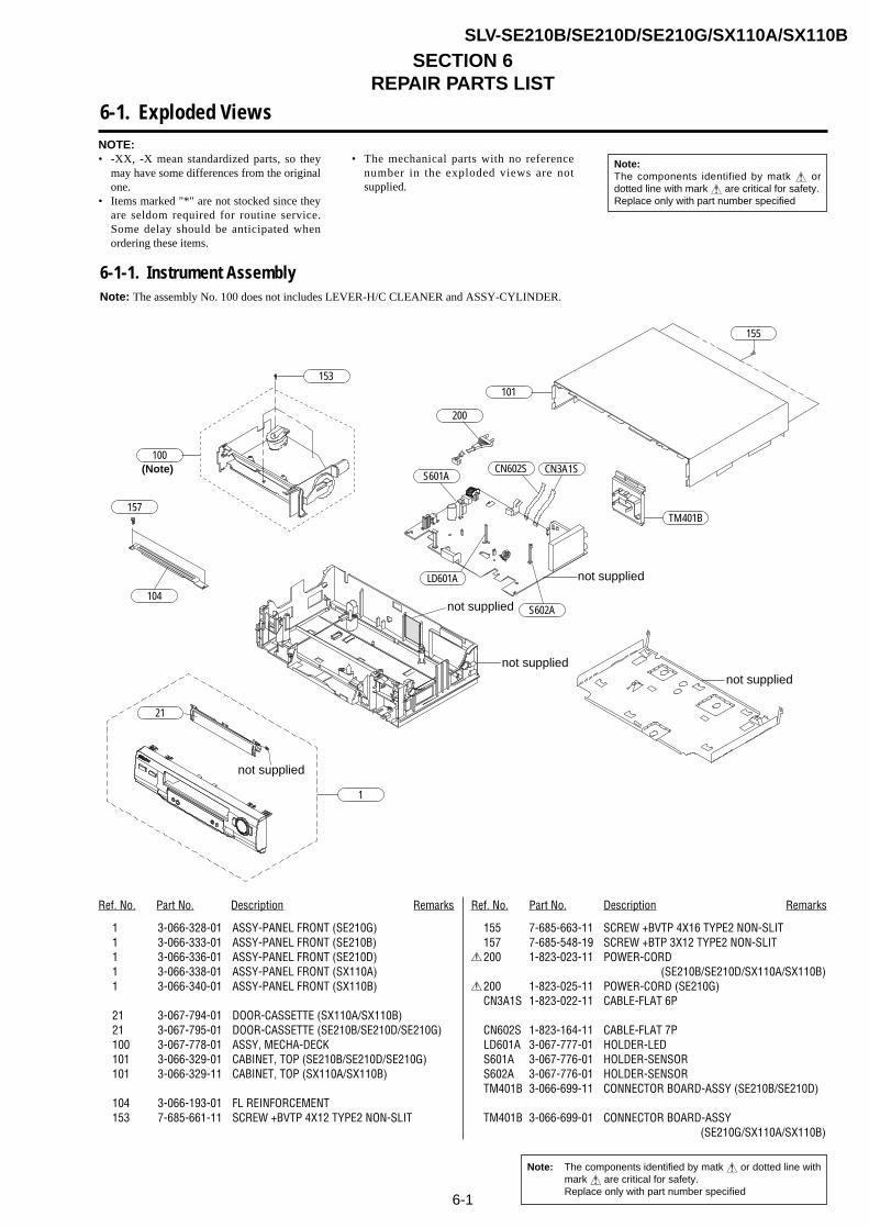
6-1. Exploded Views
6-1-1. Instrument AssemblyNote: The assembly No. 100 does not includes LEVER-H/C CLEANER and ASSY-CYLINDER.
104
TM401B
101
100
153
155
1
21
200
CN602S CN3A1S
not supplied
S601A
LD601A
S602A
not supplied
157
not supplied
not suppliednot supplied
(Note)
Ref. No. Part No. Description Remarks Ref. No. Part No. Description Remarks
1 3-066-328-01 ASSY-PANEL FRONT (SE210G)1 3-066-333-01 ASSY-PANEL FRONT (SE210B)1 3-066-336-01 ASSY-PANEL FRONT (SE210D)1 3-066-338-01 ASSY-PANEL FRONT (SX110A)1 3-066-340-01 ASSY-PANEL FRONT (SX110B)
21 3-067-794-01 DOOR-CASSETTE (SX110A/SX110B)21 3-067-795-01 DOOR-CASSETTE (SE210B/SE210D/SE210G)100 3-067-778-01 ASSY, MECHA-DECK101 3-066-329-01 CABINET, TOP (SE210B/SE210D/SE210G)101 3-066-329-11 CABINET, TOP (SX110A/SX110B)
104 3-066-193-01 FL REINFORCEMENT153 7-685-661-11 SCREW +BVTP 4X12 TYPE2 NON-SLIT
155 7-685-663-11 SCREW +BVTP 4X16 TYPE2 NON-SLIT157 7-685-548-19 SCREW +BTP 3X12 TYPE2 NON-SLIT
0200 1-823-023-11 POWER-CORD (SE210B/SE210D/SX110A/SX110B)
0200 1-823-025-11 POWER-CORD (SE210G)CN3A1S 1-823-022-11 CABLE-FLAT 6P
CN602S 1-823-164-11 CABLE-FLAT 7PLD601A 3-067-777-01 HOLDER-LEDS601A 3-067-776-01 HOLDER-SENSORS602A 3-067-776-01 HOLDER-SENSORTM401B 3-066-699-11 CONNECTOR BOARD-ASSY (SE210B/SE210D)
TM401B 3-066-699-01 CONNECTOR BOARD-ASSY (SE210G/SX110A/SX110B)
NOTE:• -XX, -X mean standardized parts, so they
may have some differences from the originalone.
• Items marked "*" are not stocked since theyare seldom required for routine service.Some delay should be anticipated whenordering these items.
• The mechanical parts with no referencenumber in the exploded views are notsupplied.
Note:The components identified by matk ! ordotted line with mark ! are critical for safety.Replace only with part number specified
Note: The components identified by matk ! or dotted line withmark ! are critical for safety.Replace only with part number specified

6-2
6-1-2. Mechanical Parts (Top Side)
G001
G555
G510
G480 K546
B410
B575
B440
G546
G060
G520
G527
K240
K248
K350
K340
G070
K250
K490
not supplied
not supplied not supplied
not supplied
not suppliednot supplied
not supplied
not supplied
not supplied
not supplied
not supplied
not supplied
not supplied
not supplied
not supplied
Ref. No. Part No. Description Remarks Ref. No. Part No. Description Remarks
B410 1-763-704-11 MOTOR-LOADING ASSYB440 7-682-144-01 SCREW-MACHINE +P 3X3B575 3-070-041-01 DAMPER-CAPSTAN G001 1-763-706-11 ASSY-CYLINDER (PAL)
(SE210B/SE210D/SX110A/SX110B)G001 1-763-707-11 ASSY-CYLINDER (PAL)(SE210G)
G060 7-682-647-01 SCREW-ASSY MACH +PS 3X6G070 3-067-796-01 PLATE-GROUND DECKG480 1-500-698-11 HEAD-ACE ASSG510 7-621-759-35 SCREW-ASSY TAPT +PSW 2.6X5YG520 3-067-779-01 LEVER-#9 GUIDE ASSY
G527 3-067-780-01 SPRING-#9 GUIDEG546 3-067-787-01 LEVER-FL DOORG555 3-067-784-01 LEVER-UNIT PINCH ASSYK240 3-067-781-01 LEVER-TENSION ASSYK248 3-067-782-01 SPRING-TENSION LEVER
K250 3-067-783-01 BAND-BRAKE ASSYK340 3-067-785-01 LEVER-T.BRAKE ASSYK350 3-067-786-01 SPRING-BRAKEK490 3-067-788-01 HOLDER-FL CASS. ASSYK546 3-067-789-01 GUIDE-CASS. DOOR
G542
B560
B570
not supplied
not suppliednot supplied
not supplied
not supplied
not supplied
not supplied
not supplied
not supplied
not supplied not supplied
6-3
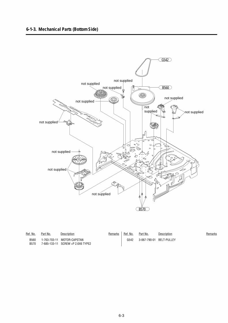
Ref. No. Part No. Description Remarks Ref. No. Part No. Description Remarks
B560 1-763-703-11 MOTOR-CAPSTANB570 7-685-133-11 SCREW +P 2.6X6 TYPE2
G542 3-067-790-01 BELT-PULLEY
6-1-3. Mechanical Parts (Bottom Side)

6-4
6-2. Electrical Parts ListNOTE:• Due to standardization, replacements
in the parts list may be different fromthe parts specified in the diagrams orthe components used on the set.
• -XX, -X mean standardized parts, sothey may have some difference fromthe original one.
• Items marked “*” are not stocked sincethey are seldom required for routineservice. Some delay should be anticipatedwhen ordering these items.
• CAPACITORS:uF: µF
• RESISTORSAll resistors are in ohms.METAL: metal-film resistorMETAL OXIDE: Metal Oxide-film resistorF: nonflammable
• COILSuH: µH
• SEMICONDUCTORSIn each case, u: µ, for example:uA...: µA... , uPA... , µPA... ,uPB... , µPB... , uPC... , µPC... ,uPD..., µPD...
• The letter “C” after the ref. No. indicates thechip part.
When indicating parts by reference number,please include the board name.
Note:The components identified by matk ! ordotted line with mark ! are critical for safety.Replace only with part number specified
Ref. No. Part No. Description Remarks Ref. No. Part No. Description Remarks
MAIN BOARD COMPLETE********************
< FERRITE CORE >
BD1SD1 1-400-085-11 INDUCTOR 70uHBD1SR1 1-400-086-11 FERRITE COREBD1SS2 1-400-085-11 INDUCTOR 70uHBD1SS3 1-400-086-11 FERRITE CORE
< CAPACITOR >
C1P102 1-126-790-11 ELECT 47uF 20% 25VC1P103 1-126-458-61 ELECT 1uF 20% 50VC1P104 1-126-794-11 ELECT 4.7uF 20% 50VC1P105 1-126-786-11 ELECT 47uF 20% 16VC1P106 1-126-786-11 ELECT 47uF 20% 16V
C1P108 1-119-943-11 ELECT 47uF 20% 50VC1SD03 1-165-557-11 CERAMIC DISC 0.0022uF 20% 400VC1SD04 1-165-557-11 CERAMIC DISC 0.0022uF 20% 400VC1SD11 1-165-577-11 ELECT 47uF 20% 400VC1SD12 1-165-574-11 FILM MPEF 0.01uF 10% 630V
C1SD13 1-165-567-11 FILM PEF 0.0012uF 10% 50VC1SR12 1-124-285-11 ELECT 22uF 20% 16VC1SR14 1-165-571-11 FILM PEF 0.0047uF 5% 50V
0C1SS01 1-165-573-11 FILM MPEF 0.1uF 20% 275V0C1SS02 1-165-573-11 FILM MPEF 0.1uF 20% 275V
C1SS03 1-165-567-11 FILM PEF 0.0012uF 10% 50VC1SS31 1-128-582-11 ELECT 10uF 20% 100VC1SS32 1-126-970-11 ELECT 330uF 20% 50VC1SS33 1-126-940-11 ELECT 330uF 20% 25VC1SS34 1-126-940-11 ELECT 330uF 20% 25V
C1SS35 1-126-926-11 ELECT 1000uF 20% 10VC1SS36 1-126-925-11 ELECT 470uF 20% 10VC1SS39 1-136-497-11 FILM PEF 0.1uF 5% 50VC301 1-126-460-11 ELECT 2.2uF 20% 50VC302 1-165-566-11 FILM PEF 0.047uF 5% 100V
C303 1-126-458-61 ELECT 1uF 20% 50VC304C 1-163-237-11 CERAMIC CHIP 27pF 5% 50VC305 1-165-561-11 CERAMIC MLC-AXIAL 180pF 10% 50VC306 1-165-562-11 CERAMIC MLC-AXIAL 330pF 10% 50VC307C 1-163-231-11 CERAMIC CHIP 15pF 5% 50V
C308C 1-163-021-11 CERAMIC CHIP 0.01uF 10% 50VC309 1-126-458-61 ELECT 1uF 20% 50VC310 1-126-109-11 ELECT 10uF 20% 16VC311 1-126-435-71 ELECT 22uF 20% 16VC313C 1-163-275-11 CERAMIC CHIP 0.001uF 10% 50V
C314 1-126-456-11 ELECT 0.47uF 20% 50VC315 1-126-109-11 ELECT 10uF 20% 16VC316C 1-164-343-11 CERAMIC CHIP 0.056uF 10% 50VC318C 1-115-339-11 CERAMIC CHIP 0.1uF +80-20% 50VC320 1-126-458-61 ELECT 1uF 20% 50V
C321 1-126-109-11 ELECT 10uF 20% 16VC322 1-126-458-61 ELECT 1uF 20% 50VC323C 1-163-021-11 CERAMIC CHIP 0.01uF 10% 50VC324C 1-163-021-11 CERAMIC CHIP 0.01uF 10% 50VC325 1-161-330-11 CERAMIC MLC-AXIAL 0.01uF 30% 16V
C326 1-165-563-11 CERAMIC MLC-AXIAL 0.1uF 80-20%C327 1-126-437-11 ELECT 47uF 20% 16VC328 1-126-330-11 CERAMIC MLC-AXIAL 0.01uF 30% 16VC329 1-126-330-11 CERAMIC MLC-AXIAL 0.01uF 30% 16VC330 1-126-330-11 CERAMIC MLC-AXIAL 0.01uF 30% 16V
C331 1-126-437-11 ELECT 47uF 20% 16VC332C 1-115-339-11 CERAMIC CHIP 0.1uF +80-20% 50VC333 1-126-458-61 ELECT 1uF 20% 50VC334C 1-163-021-11 CERAMIC CHIP 0.01uF 10% 50VC335 1-126-458-61 ELECT 1uF 20% 50V
C336 1-126-458-61 ELECT 1uF 20% 50VC337 1-161-494-11 CERAMIC MLC-AXIAL 0.022uF +80-20%C338C 1-163-021-11 CERAMIC CHIP 0.01uF 10% 50VC339C 1-104-760-11 CERAMIC CHIP 0.047uF 10% 50VC340C 1-163-033-11 CERAMIC CHIP 0.022uF 10% 50V
C341 1-126-437-11 ELECT 47uF 20% 16VC342 1-165-563-11 CERAMIC MLC-AXIAL 0.1uF 80-20% 50VC343C 1-163-021-11 CERAMIC CHIP 0.01uF 10% 50VC345C 1-163-222-11 CERAMIC CHIP 5pF 0.25pF 50VC346 1-126-786-11 ELECT 47uF 20% 16V
C347C 1-163-006-11 CERAMIC CHIP 56pF 5% 50VC348C 1-163-006-11 CERAMIC CHIP 56pF 5% 50VC349C 1-163-233-11 CERAMIC CHIP 18pF 5% 50VC350C 1-163-021-11 CERAMIC CHIP 0.01uF 10% 50VC380C 1-163-238-11 CERAMIC CHIP 30pF 5% 50V
C381 1-161-330-11 CERAMIC MLC-AXIAL 0.01uF 30% 16VC390 1-165-563-11 CERAMIC MLC-AXIAL 0.1uF 80-20% 50VC393 1-161-259-11 CERAMIC MLC-AXIAL 10pF 5% 50VC399 1-165-563-11 CERAMIC MLC-AXIAL 0.1uF 80-20% 50VC3A01 1-126-794-11 ELECT 4.7uF 20% 50V
C3A02C 1-115-339-11 CERAMIC CHIP 0.1uF +80-20% 50VC3A04C 1-115-339-11 CERAMIC CHIP 0.1uF +80-20% 50VC3A08 1-136-485-11 FILM PEF 0.01uF 5% 50VC3A09 1-165-572-11 FILM PEF 0.0068uF 5% 50VC3A10C 1-163-020-11 CERAMIC CHIP 0.0082uF 10% 50V
MAIN
Note: The components identified by matk ! or dotted line withmark ! are critical for safety.Replace only with part number specified
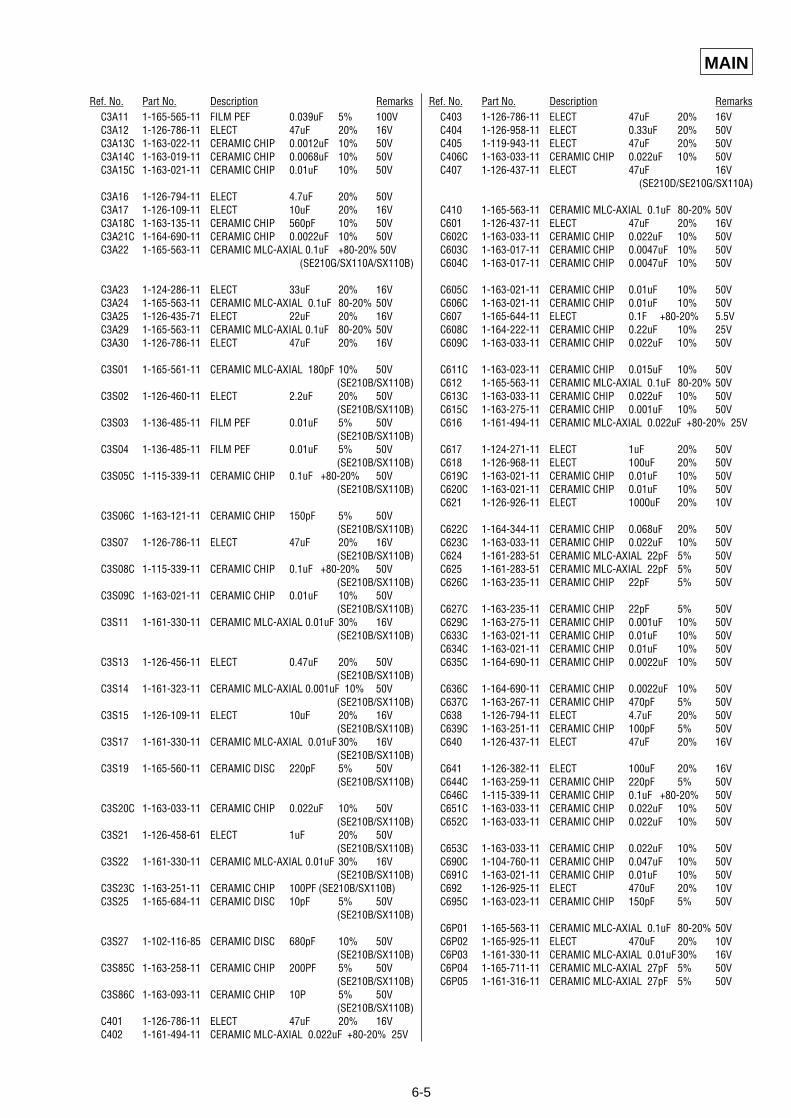
6-5
MAIN
Ref. No. Part No. Description Remarks Ref. No. Part No. Description RemarksC3A11 1-165-565-11 FILM PEF 0.039uF 5% 100VC3A12 1-126-786-11 ELECT 47uF 20% 16VC3A13C 1-163-022-11 CERAMIC CHIP 0.0012uF 10% 50VC3A14C 1-163-019-11 CERAMIC CHIP 0.0068uF 10% 50VC3A15C 1-163-021-11 CERAMIC CHIP 0.01uF 10% 50V
C3A16 1-126-794-11 ELECT 4.7uF 20% 50VC3A17 1-126-109-11 ELECT 10uF 20% 16VC3A18C 1-163-135-11 CERAMIC CHIP 560pF 10% 50VC3A21C 1-164-690-11 CERAMIC CHIP 0.0022uF 10% 50VC3A22 1-165-563-11 CERAMIC MLC-AXIAL 0.1uF +80-20% 50V
(SE210G/SX110A/SX110B)
C3A23 1-124-286-11 ELECT 33uF 20% 16VC3A24 1-165-563-11 CERAMIC MLC-AXIAL 0.1uF 80-20% 50VC3A25 1-126-435-71 ELECT 22uF 20% 16VC3A29 1-165-563-11 CERAMIC MLC-AXIAL 0.1uF 80-20% 50VC3A30 1-126-786-11 ELECT 47uF 20% 16V
C3S01 1-165-561-11 CERAMIC MLC-AXIAL 180pF 10% 50V(SE210B/SX110B)
C3S02 1-126-460-11 ELECT 2.2uF 20% 50V(SE210B/SX110B)
C3S03 1-136-485-11 FILM PEF 0.01uF 5% 50V(SE210B/SX110B)
C3S04 1-136-485-11 FILM PEF 0.01uF 5% 50V(SE210B/SX110B)
C3S05C 1-115-339-11 CERAMIC CHIP 0.1uF +80-20% 50V(SE210B/SX110B)
C3S06C 1-163-121-11 CERAMIC CHIP 150pF 5% 50V(SE210B/SX110B)
C3S07 1-126-786-11 ELECT 47uF 20% 16V(SE210B/SX110B)
C3S08C 1-115-339-11 CERAMIC CHIP 0.1uF +80-20% 50V(SE210B/SX110B)
C3S09C 1-163-021-11 CERAMIC CHIP 0.01uF 10% 50V(SE210B/SX110B)
C3S11 1-161-330-11 CERAMIC MLC-AXIAL 0.01uF 30% 16V(SE210B/SX110B)
C3S13 1-126-456-11 ELECT 0.47uF 20% 50V(SE210B/SX110B)
C3S14 1-161-323-11 CERAMIC MLC-AXIAL 0.001uF 10% 50V(SE210B/SX110B)
C3S15 1-126-109-11 ELECT 10uF 20% 16V(SE210B/SX110B)
C3S17 1-161-330-11 CERAMIC MLC-AXIAL 0.01uF 30% 16V(SE210B/SX110B)
C3S19 1-165-560-11 CERAMIC DISC 220pF 5% 50V(SE210B/SX110B)
C3S20C 1-163-033-11 CERAMIC CHIP 0.022uF 10% 50V(SE210B/SX110B)
C3S21 1-126-458-61 ELECT 1uF 20% 50V(SE210B/SX110B)
C3S22 1-161-330-11 CERAMIC MLC-AXIAL 0.01uF 30% 16V(SE210B/SX110B)
C3S23C 1-163-251-11 CERAMIC CHIP 100PF (SE210B/SX110B)C3S25 1-165-684-11 CERAMIC DISC 10pF 5% 50V
(SE210B/SX110B)
C3S27 1-102-116-85 CERAMIC DISC 680pF 10% 50V(SE210B/SX110B)
C3S85C 1-163-258-11 CERAMIC CHIP 200PF 5% 50V(SE210B/SX110B)
C3S86C 1-163-093-11 CERAMIC CHIP 10P 5% 50V(SE210B/SX110B)
C401 1-126-786-11 ELECT 47uF 20% 16VC402 1-161-494-11 CERAMIC MLC-AXIAL 0.022uF +80-20% 25V
C403 1-126-786-11 ELECT 47uF 20% 16VC404 1-126-958-11 ELECT 0.33uF 20% 50VC405 1-119-943-11 ELECT 47uF 20% 50VC406C 1-163-033-11 CERAMIC CHIP 0.022uF 10% 50VC407 1-126-437-11 ELECT 47uF 16V
(SE210D/SE210G/SX110A)
C410 1-165-563-11 CERAMIC MLC-AXIAL 0.1uF 80-20% 50VC601 1-126-437-11 ELECT 47uF 20% 16VC602C 1-163-033-11 CERAMIC CHIP 0.022uF 10% 50VC603C 1-163-017-11 CERAMIC CHIP 0.0047uF 10% 50VC604C 1-163-017-11 CERAMIC CHIP 0.0047uF 10% 50V
C605C 1-163-021-11 CERAMIC CHIP 0.01uF 10% 50VC606C 1-163-021-11 CERAMIC CHIP 0.01uF 10% 50VC607 1-165-644-11 ELECT 0.1F +80-20% 5.5VC608C 1-164-222-11 CERAMIC CHIP 0.22uF 10% 25VC609C 1-163-033-11 CERAMIC CHIP 0.022uF 10% 50V
C611C 1-163-023-11 CERAMIC CHIP 0.015uF 10% 50VC612 1-165-563-11 CERAMIC MLC-AXIAL 0.1uF 80-20% 50VC613C 1-163-033-11 CERAMIC CHIP 0.022uF 10% 50VC615C 1-163-275-11 CERAMIC CHIP 0.001uF 10% 50VC616 1-161-494-11 CERAMIC MLC-AXIAL 0.022uF +80-20% 25V
C617 1-124-271-11 ELECT 1uF 20% 50VC618 1-126-968-11 ELECT 100uF 20% 50VC619C 1-163-021-11 CERAMIC CHIP 0.01uF 10% 50VC620C 1-163-021-11 CERAMIC CHIP 0.01uF 10% 50VC621 1-126-926-11 ELECT 1000uF 20% 10V
C622C 1-164-344-11 CERAMIC CHIP 0.068uF 20% 50VC623C 1-163-033-11 CERAMIC CHIP 0.022uF 10% 50VC624 1-161-283-51 CERAMIC MLC-AXIAL 22pF 5% 50VC625 1-161-283-51 CERAMIC MLC-AXIAL 22pF 5% 50VC626C 1-163-235-11 CERAMIC CHIP 22pF 5% 50V
C627C 1-163-235-11 CERAMIC CHIP 22pF 5% 50VC629C 1-163-275-11 CERAMIC CHIP 0.001uF 10% 50VC633C 1-163-021-11 CERAMIC CHIP 0.01uF 10% 50VC634C 1-163-021-11 CERAMIC CHIP 0.01uF 10% 50VC635C 1-164-690-11 CERAMIC CHIP 0.0022uF 10% 50V
C636C 1-164-690-11 CERAMIC CHIP 0.0022uF 10% 50VC637C 1-163-267-11 CERAMIC CHIP 470pF 5% 50VC638 1-126-794-11 ELECT 4.7uF 20% 50VC639C 1-163-251-11 CERAMIC CHIP 100pF 5% 50VC640 1-126-437-11 ELECT 47uF 20% 16V
C641 1-126-382-11 ELECT 100uF 20% 16VC644C 1-163-259-11 CERAMIC CHIP 220pF 5% 50VC646C 1-115-339-11 CERAMIC CHIP 0.1uF +80-20% 50VC651C 1-163-033-11 CERAMIC CHIP 0.022uF 10% 50VC652C 1-163-033-11 CERAMIC CHIP 0.022uF 10% 50V
C653C 1-163-033-11 CERAMIC CHIP 0.022uF 10% 50VC690C 1-104-760-11 CERAMIC CHIP 0.047uF 10% 50VC691C 1-163-021-11 CERAMIC CHIP 0.01uF 10% 50VC692 1-126-925-11 ELECT 470uF 20% 10VC695C 1-163-023-11 CERAMIC CHIP 150pF 5% 50V
C6P01 1-165-563-11 CERAMIC MLC-AXIAL 0.1uF 80-20% 50VC6P02 1-165-925-11 ELECT 470uF 20% 10VC6P03 1-161-330-11 CERAMIC MLC-AXIAL 0.01uF 30% 16VC6P04 1-165-711-11 CERAMIC MLC-AXIAL 27pF 5% 50VC6P05 1-161-316-11 CERAMIC MLC-AXIAL 27pF 5% 50V
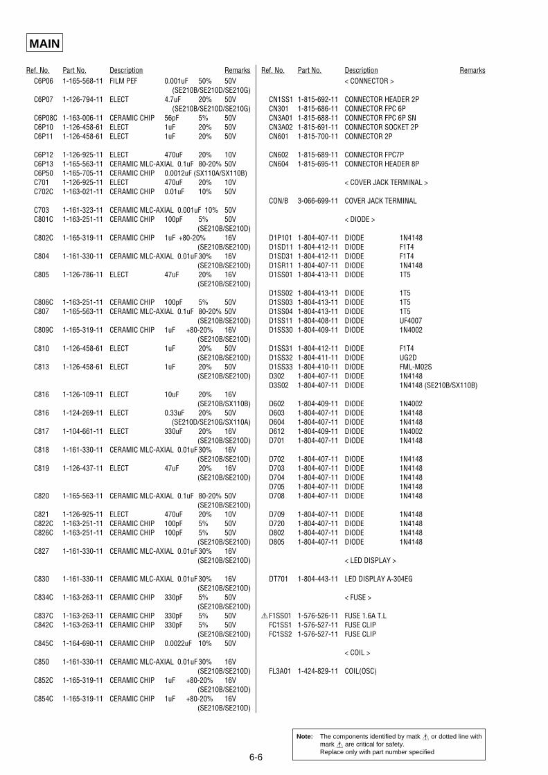
6-6
MAIN
Ref. No. Part No. Description Remarks Ref. No. Part No. Description RemarksC6P06 1-165-568-11 FILM PEF 0.001uF 50% 50V
(SE210B/SE210D/SE210G)C6P07 1-126-794-11 ELECT 4.7uF 20% 50V
(SE210B/SE210D/SE210G)C6P08C 1-163-006-11 CERAMIC CHIP 56pF 5% 50VC6P10 1-126-458-61 ELECT 1uF 20% 50VC6P11 1-126-458-61 ELECT 1uF 20% 50V
C6P12 1-126-925-11 ELECT 470uF 20% 10VC6P13 1-165-563-11 CERAMIC MLC-AXIAL 0.1uF 80-20% 50VC6P50 1-165-705-11 CERAMIC CHIP 0.0012uF (SX110A/SX110B)C701 1-126-925-11 ELECT 470uF 20% 10VC702C 1-163-021-11 CERAMIC CHIP 0.01uF 10% 50V
C703 1-161-323-11 CERAMIC MLC-AXIAL 0.001uF 10% 50VC801C 1-163-251-11 CERAMIC CHIP 100pF 5% 50V
(SE210B/SE210D)C802C 1-165-319-11 CERAMIC CHIP 1uF +80-20% 16V
(SE210B/SE210D)C804 1-161-330-11 CERAMIC MLC-AXIAL 0.01uF 30% 16V
(SE210B/SE210D)C805 1-126-786-11 ELECT 47uF 20% 16V
(SE210B/SE210D)
C806C 1-163-251-11 CERAMIC CHIP 100pF 5% 50VC807 1-165-563-11 CERAMIC MLC-AXIAL 0.1uF 80-20% 50V
(SE210B/SE210D)C809C 1-165-319-11 CERAMIC CHIP 1uF +80-20% 16V
(SE210B/SE210D)C810 1-126-458-61 ELECT 1uF 20% 50V
(SE210B/SE210D)C813 1-126-458-61 ELECT 1uF 20% 50V
(SE210B/SE210D)
C816 1-126-109-11 ELECT 10uF 20% 16V(SE210B/SX110B)
C816 1-124-269-11 ELECT 0.33uF 20% 50V (SE210D/SE210G/SX110A)
C817 1-104-661-11 ELECT 330uF 20% 16V(SE210B/SE210D)
C818 1-161-330-11 CERAMIC MLC-AXIAL 0.01uF 30% 16V(SE210B/SE210D)
C819 1-126-437-11 ELECT 47uF 20% 16V(SE210B/SE210D)
C820 1-165-563-11 CERAMIC MLC-AXIAL 0.1uF 80-20% 50V(SE210B/SE210D)
C821 1-126-925-11 ELECT 470uF 20% 10VC822C 1-163-251-11 CERAMIC CHIP 100pF 5% 50VC826C 1-163-251-11 CERAMIC CHIP 100pF 5% 50V
(SE210B/SE210D)C827 1-161-330-11 CERAMIC MLC-AXIAL 0.01uF 30% 16V
(SE210B/SE210D)
C830 1-161-330-11 CERAMIC MLC-AXIAL 0.01uF 30% 16V(SE210B/SE210D)
C834C 1-163-263-11 CERAMIC CHIP 330pF 5% 50V(SE210B/SE210D)
C837C 1-163-263-11 CERAMIC CHIP 330pF 5% 50VC842C 1-163-263-11 CERAMIC CHIP 330pF 5% 50V
(SE210B/SE210D)C845C 1-164-690-11 CERAMIC CHIP 0.0022uF 10% 50V
C850 1-161-330-11 CERAMIC MLC-AXIAL 0.01uF 30% 16V(SE210B/SE210D)
C852C 1-165-319-11 CERAMIC CHIP 1uF +80-20% 16V(SE210B/SE210D)
C854C 1-165-319-11 CERAMIC CHIP 1uF +80-20% 16V(SE210B/SE210D)
< CONNECTOR >
CN1SS1 1-815-692-11 CONNECTOR HEADER 2PCN301 1-815-686-11 CONNECTOR FPC 6PCN3A01 1-815-688-11 CONNECTOR FPC 6P SNCN3A02 1-815-691-11 CONNECTOR SOCKET 2PCN601 1-815-700-11 CONNECTOR 2P
CN602 1-815-689-11 CONNECTOR FPC7PCN604 1-815-695-11 CONNECTOR HEADER 8P
< COVER JACK TERMINAL >
CON/B 3-066-699-11 COVER JACK TERMINAL
< DIODE >
D1P101 1-804-407-11 DIODE 1N4148D1SD11 1-804-412-11 DIODE F1T4D1SD31 1-804-412-11 DIODE F1T4D1SR11 1-804-407-11 DIODE 1N4148D1SS01 1-804-413-11 DIODE 1T5
D1SS02 1-804-413-11 DIODE 1T5D1SS03 1-804-413-11 DIODE 1T5D1SS04 1-804-413-11 DIODE 1T5D1SS11 1-804-408-11 DIODE UF4007D1SS30 1-804-409-11 DIODE 1N4002
D1SS31 1-804-412-11 DIODE F1T4D1SS32 1-804-411-11 DIODE UG2DD1SS33 1-804-410-11 DIODE FML-M02SD302 1-804-407-11 DIODE 1N4148D3S02 1-804-407-11 DIODE 1N4148 (SE210B/SX110B)
D602 1-804-409-11 DIODE 1N4002D603 1-804-407-11 DIODE 1N4148D604 1-804-407-11 DIODE 1N4148D612 1-804-409-11 DIODE 1N4002D701 1-804-407-11 DIODE 1N4148
D702 1-804-407-11 DIODE 1N4148D703 1-804-407-11 DIODE 1N4148D704 1-804-407-11 DIODE 1N4148D705 1-804-407-11 DIODE 1N4148D708 1-804-407-11 DIODE 1N4148
D709 1-804-407-11 DIODE 1N4148D720 1-804-407-11 DIODE 1N4148D802 1-804-407-11 DIODE 1N4148D805 1-804-407-11 DIODE 1N4148
< LED DISPLAY >
DT701 1-804-443-11 LED DISPLAY A-304EG
< FUSE >
0F1SS01 1-576-526-11 FUSE 1.6A T.LFC1SS1 1-576-527-11 FUSE CLIPFC1SS2 1-576-527-11 FUSE CLIP
< COIL >
FL3A01 1-424-829-11 COIL(OSC)
Note: The components identified by matk ! or dotted line withmark ! are critical for safety.Replace only with part number specified
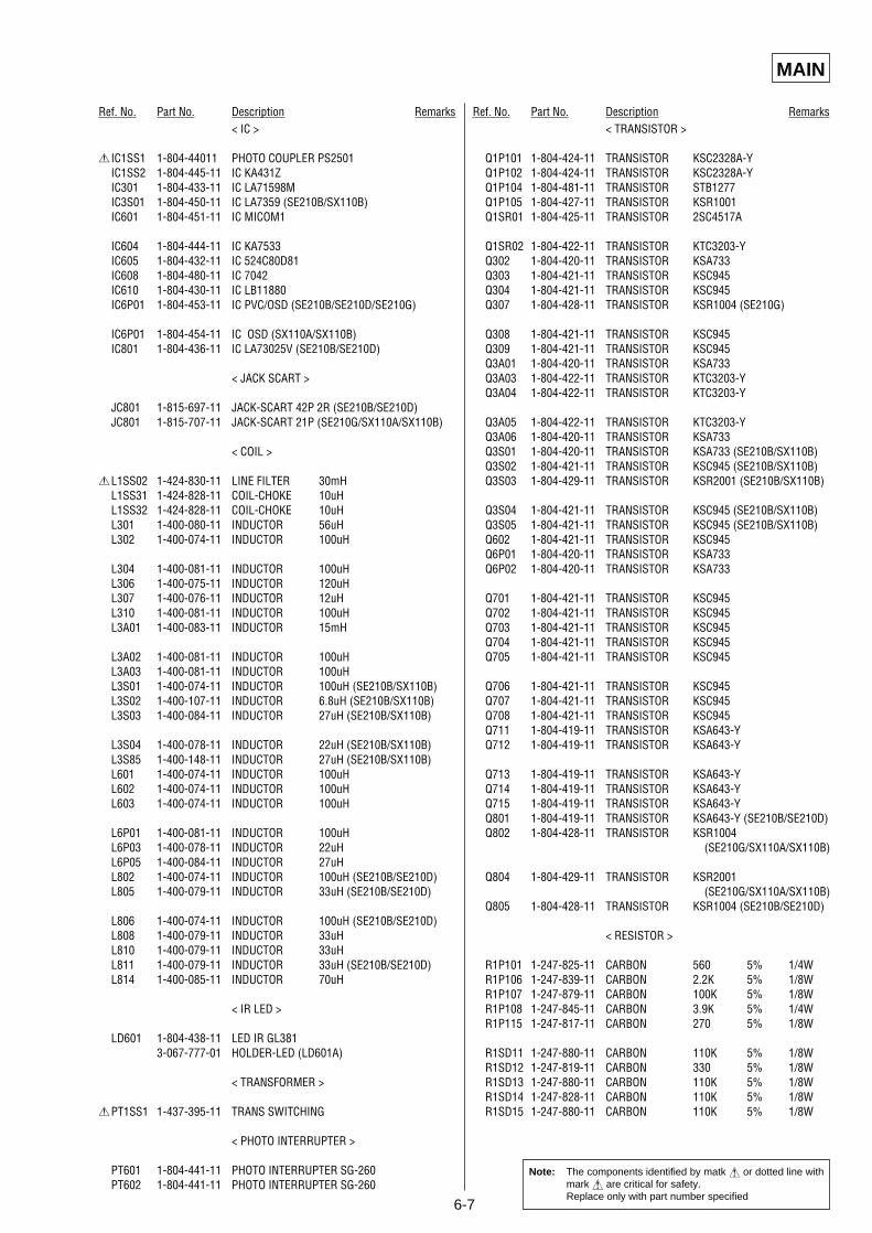
6-7
MAIN
Ref. No. Part No. Description Remarks Ref. No. Part No. Description Remarks< IC >
0 IC1SS1 1-804-44011 PHOTO COUPLER PS2501IC1SS2 1-804-445-11 IC KA431ZIC301 1-804-433-11 IC LA71598MIC3S01 1-804-450-11 IC LA7359 (SE210B/SX110B)IC601 1-804-451-11 IC MICOM1
IC604 1-804-444-11 IC KA7533IC605 1-804-432-11 IC 524C80D81IC608 1-804-480-11 IC 7042IC610 1-804-430-11 IC LB11880IC6P01 1-804-453-11 IC PVC/OSD (SE210B/SE210D/SE210G)
IC6P01 1-804-454-11 IC OSD (SX110A/SX110B)IC801 1-804-436-11 IC LA73025V (SE210B/SE210D)
< JACK SCART >
JC801 1-815-697-11 JACK-SCART 42P 2R (SE210B/SE210D)JC801 1-815-707-11 JACK-SCART 21P (SE210G/SX110A/SX110B)
< COIL >
0L1SS02 1-424-830-11 LINE FILTER 30mHL1SS31 1-424-828-11 COIL-CHOKE 10uHL1SS32 1-424-828-11 COIL-CHOKE 10uHL301 1-400-080-11 INDUCTOR 56uHL302 1-400-074-11 INDUCTOR 100uH
L304 1-400-081-11 INDUCTOR 100uHL306 1-400-075-11 INDUCTOR 120uHL307 1-400-076-11 INDUCTOR 12uHL310 1-400-081-11 INDUCTOR 100uHL3A01 1-400-083-11 INDUCTOR 15mH
L3A02 1-400-081-11 INDUCTOR 100uHL3A03 1-400-081-11 INDUCTOR 100uHL3S01 1-400-074-11 INDUCTOR 100uH (SE210B/SX110B)L3S02 1-400-107-11 INDUCTOR 6.8uH (SE210B/SX110B)L3S03 1-400-084-11 INDUCTOR 27uH (SE210B/SX110B)
L3S04 1-400-078-11 INDUCTOR 22uH (SE210B/SX110B)L3S85 1-400-148-11 INDUCTOR 27uH (SE210B/SX110B)L601 1-400-074-11 INDUCTOR 100uHL602 1-400-074-11 INDUCTOR 100uHL603 1-400-074-11 INDUCTOR 100uH
L6P01 1-400-081-11 INDUCTOR 100uHL6P03 1-400-078-11 INDUCTOR 22uHL6P05 1-400-084-11 INDUCTOR 27uHL802 1-400-074-11 INDUCTOR 100uH (SE210B/SE210D)L805 1-400-079-11 INDUCTOR 33uH (SE210B/SE210D)
L806 1-400-074-11 INDUCTOR 100uH (SE210B/SE210D)L808 1-400-079-11 INDUCTOR 33uHL810 1-400-079-11 INDUCTOR 33uHL811 1-400-079-11 INDUCTOR 33uH (SE210B/SE210D)L814 1-400-085-11 INDUCTOR 70uH
< IR LED >
LD601 1-804-438-11 LED IR GL3813-067-777-01 HOLDER-LED (LD601A)
< TRANSFORMER >
0PT1SS1 1-437-395-11 TRANS SWITCHING
< PHOTO INTERRUPTER >
PT601 1-804-441-11 PHOTO INTERRUPTER SG-260PT602 1-804-441-11 PHOTO INTERRUPTER SG-260
< TRANSISTOR >
Q1P101 1-804-424-11 TRANSISTOR KSC2328A-YQ1P102 1-804-424-11 TRANSISTOR KSC2328A-YQ1P104 1-804-481-11 TRANSISTOR STB1277Q1P105 1-804-427-11 TRANSISTOR KSR1001Q1SR01 1-804-425-11 TRANSISTOR 2SC4517A
Q1SR02 1-804-422-11 TRANSISTOR KTC3203-YQ302 1-804-420-11 TRANSISTOR KSA733Q303 1-804-421-11 TRANSISTOR KSC945Q304 1-804-421-11 TRANSISTOR KSC945Q307 1-804-428-11 TRANSISTOR KSR1004 (SE210G)
Q308 1-804-421-11 TRANSISTOR KSC945Q309 1-804-421-11 TRANSISTOR KSC945Q3A01 1-804-420-11 TRANSISTOR KSA733Q3A03 1-804-422-11 TRANSISTOR KTC3203-YQ3A04 1-804-422-11 TRANSISTOR KTC3203-Y
Q3A05 1-804-422-11 TRANSISTOR KTC3203-YQ3A06 1-804-420-11 TRANSISTOR KSA733Q3S01 1-804-420-11 TRANSISTOR KSA733 (SE210B/SX110B)Q3S02 1-804-421-11 TRANSISTOR KSC945 (SE210B/SX110B)Q3S03 1-804-429-11 TRANSISTOR KSR2001 (SE210B/SX110B)
Q3S04 1-804-421-11 TRANSISTOR KSC945 (SE210B/SX110B)Q3S05 1-804-421-11 TRANSISTOR KSC945 (SE210B/SX110B)Q602 1-804-421-11 TRANSISTOR KSC945Q6P01 1-804-420-11 TRANSISTOR KSA733Q6P02 1-804-420-11 TRANSISTOR KSA733
Q701 1-804-421-11 TRANSISTOR KSC945Q702 1-804-421-11 TRANSISTOR KSC945Q703 1-804-421-11 TRANSISTOR KSC945Q704 1-804-421-11 TRANSISTOR KSC945Q705 1-804-421-11 TRANSISTOR KSC945
Q706 1-804-421-11 TRANSISTOR KSC945Q707 1-804-421-11 TRANSISTOR KSC945Q708 1-804-421-11 TRANSISTOR KSC945Q711 1-804-419-11 TRANSISTOR KSA643-YQ712 1-804-419-11 TRANSISTOR KSA643-Y
Q713 1-804-419-11 TRANSISTOR KSA643-YQ714 1-804-419-11 TRANSISTOR KSA643-YQ715 1-804-419-11 TRANSISTOR KSA643-YQ801 1-804-419-11 TRANSISTOR KSA643-Y (SE210B/SE210D)Q802 1-804-428-11 TRANSISTOR KSR1004
(SE210G/SX110A/SX110B)
Q804 1-804-429-11 TRANSISTOR KSR2001(SE210G/SX110A/SX110B)
Q805 1-804-428-11 TRANSISTOR KSR1004 (SE210B/SE210D)
< RESISTOR >
R1P101 1-247-825-11 CARBON 560 5% 1/4WR1P106 1-247-839-11 CARBON 2.2K 5% 1/8WR1P107 1-247-879-11 CARBON 100K 5% 1/8WR1P108 1-247-845-11 CARBON 3.9K 5% 1/4WR1P115 1-247-817-11 CARBON 270 5% 1/8W
R1SD11 1-247-880-11 CARBON 110K 5% 1/8WR1SD12 1-247-819-11 CARBON 330 5% 1/8WR1SD13 1-247-880-11 CARBON 110K 5% 1/8WR1SD14 1-247-828-11 CARBON 110K 5% 1/8WR1SD15 1-247-880-11 CARBON 110K 5% 1/8W
Note: The components identified by matk ! or dotted line withmark ! are critical for safety.Replace only with part number specified
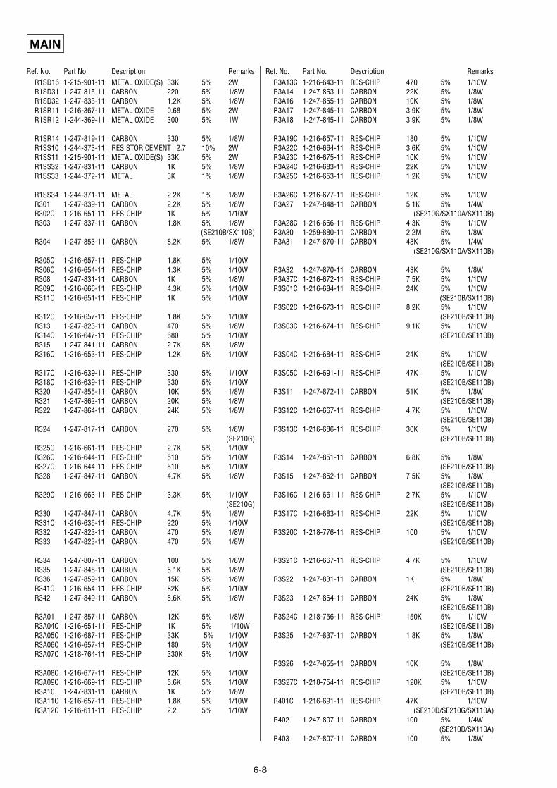
6-8
MAIN
Ref. No. Part No. Description Remarks Ref. No. Part No. Description RemarksR1SD16 1-215-901-11 METAL OXIDE(S) 33K 5% 2WR1SD31 1-247-815-11 CARBON 220 5% 1/8WR1SD32 1-247-833-11 CARBON 1.2K 5% 1/8WR1SR11 1-216-367-11 METAL OXIDE 0.68 5% 2WR1SR12 1-244-369-11 METAL OXIDE 300 5% 1W
R1SR14 1-247-819-11 CARBON 330 5% 1/8WR1SS10 1-244-373-11 RESISTOR CEMENT 2.7 10% 2WR1SS11 1-215-901-11 METAL OXIDE(S) 33K 5% 2WR1SS32 1-247-831-11 CARBON 1K 5% 1/8WR1SS33 1-244-372-11 METAL 3K 1% 1/8W
R1SS34 1-244-371-11 METAL 2.2K 1% 1/8WR301 1-247-839-11 CARBON 2.2K 5% 1/8WR302C 1-216-651-11 RES-CHIP 1K 5% 1/10WR303 1-247-837-11 CARBON 1.8K 5% 1/8W
(SE210B/SX110B)R304 1-247-853-11 CARBON 8.2K 5% 1/8W
R305C 1-216-657-11 RES-CHIP 1.8K 5% 1/10WR306C 1-216-654-11 RES-CHIP 1.3K 5% 1/10WR308 1-247-831-11 CARBON 1K 5% 1/8WR309C 1-216-666-11 RES-CHIP 4.3K 5% 1/10WR311C 1-216-651-11 RES-CHIP 1K 5% 1/10W
R312C 1-216-657-11 RES-CHIP 1.8K 5% 1/10WR313 1-247-823-11 CARBON 470 5% 1/8WR314C 1-216-647-11 RES-CHIP 680 5% 1/10WR315 1-247-841-11 CARBON 2.7K 5% 1/8WR316C 1-216-653-11 RES-CHIP 1.2K 5% 1/10W
R317C 1-216-639-11 RES-CHIP 330 5% 1/10WR318C 1-216-639-11 RES-CHIP 330 5% 1/10WR320 1-247-855-11 CARBON 10K 5% 1/8WR321 1-247-862-11 CARBON 20K 5% 1/8WR322 1-247-864-11 CARBON 24K 5% 1/8W
R324 1-247-817-11 CARBON 270 5% 1/8W(SE210G)
R325C 1-216-661-11 RES-CHIP 2.7K 5% 1/10WR326C 1-216-644-11 RES-CHIP 510 5% 1/10WR327C 1-216-644-11 RES-CHIP 510 5% 1/10WR328 1-247-847-11 CARBON 4.7K 5% 1/8W
R329C 1-216-663-11 RES-CHIP 3.3K 5% 1/10W(SE210G)
R330 1-247-847-11 CARBON 4.7K 5% 1/8WR331C 1-216-635-11 RES-CHIP 220 5% 1/10WR332 1-247-823-11 CARBON 470 5% 1/8WR333 1-247-823-11 CARBON 470 5% 1/8W
R334 1-247-807-11 CARBON 100 5% 1/8WR335 1-247-848-11 CARBON 5.1K 5% 1/8WR336 1-247-859-11 CARBON 15K 5% 1/8WR341C 1-216-654-11 RES-CHIP 82K 5% 1/10WR342 1-247-849-11 CARBON 5.6K 5% 1/8W
R3A01 1-247-857-11 CARBON 12K 5% 1/8WR3A04C 1-216-651-11 RES-CHIP 1K 5% 1/10WR3A05C 1-216-687-11 RES-CHIP 33K 5% 1/10WR3A06C 1-216-657-11 RES-CHIP 180 5% 1/10WR3A07C 1-218-764-11 RES-CHIP 330K 5% 1/10W
R3A08C 1-216-677-11 RES-CHIP 12K 5% 1/10WR3A09C 1-216-669-11 RES-CHIP 5.6K 5% 1/10WR3A10 1-247-831-11 CARBON 1K 5% 1/8WR3A11C 1-216-657-11 RES-CHIP 1.8K 5% 1/10WR3A12C 1-216-611-11 RES-CHIP 2.2 5% 1/10W
R3A13C 1-216-643-11 RES-CHIP 470 5% 1/10WR3A14 1-247-863-11 CARBON 22K 5% 1/8WR3A16 1-247-855-11 CARBON 10K 5% 1/8WR3A17 1-247-845-11 CARBON 3.9K 5% 1/8WR3A18 1-247-845-11 CARBON 3.9K 5% 1/8W
R3A19C 1-216-657-11 RES-CHIP 180 5% 1/10WR3A22C 1-216-664-11 RES-CHIP 3.6K 5% 1/10WR3A23C 1-216-675-11 RES-CHIP 10K 5% 1/10WR3A24C 1-216-683-11 RES-CHIP 22K 5% 1/10WR3A25C 1-216-653-11 RES-CHIP 1.2K 5% 1/10W
R3A26C 1-216-677-11 RES-CHIP 12K 5% 1/10WR3A27 1-247-848-11 CARBON 5.1K 5% 1/4W
(SE210G/SX110A/SX110B)R3A28C 1-216-666-11 RES-CHIP 4.3K 5% 1/10WR3A30 1-259-880-11 CARBON 2.2M 5% 1/8WR3A31 1-247-870-11 CARBON 43K 5% 1/4W
(SE210G/SX110A/SX110B)
R3A32 1-247-870-11 CARBON 43K 5% 1/8WR3A37C 1-216-672-11 RES-CHIP 7.5K 5% 1/10WR3S01C 1-216-684-11 RES-CHIP 24K 5% 1/10W
(SE210B/SX110B)R3S02C 1-216-673-11 RES-CHIP 8.2K 5% 1/10W
(SE210B/SE110B)R3S03C 1-216-674-11 RES-CHIP 9.1K 5% 1/10W
(SE210B/SE110B)
R3S04C 1-216-684-11 RES-CHIP 24K 5% 1/10W(SE210B/SE110B)
R3S05C 1-216-691-11 RES-CHIP 47K 5% 1/10W(SE210B/SE110B)
R3S11 1-247-872-11 CARBON 51K 5% 1/8W(SE210B/SE110B)
R3S12C 1-216-667-11 RES-CHIP 4.7K 5% 1/10W(SE210B/SE110B)
R3S13C 1-216-686-11 RES-CHIP 30K 5% 1/10W(SE210B/SE110B)
R3S14 1-247-851-11 CARBON 6.8K 5% 1/8W(SE210B/SE110B)
R3S15 1-247-852-11 CARBON 7.5K 5% 1/8W(SE210B/SE110B)
R3S16C 1-216-661-11 RES-CHIP 2.7K 5% 1/10W(SE210B/SE110B)
R3S17C 1-216-683-11 RES-CHIP 22K 5% 1/10W(SE210B/SE110B)
R3S20C 1-218-776-11 RES-CHIP 100 5% 1/10W(SE210B/SE110B)
R3S21C 1-216-667-11 RES-CHIP 4.7K 5% 1/10W(SE210B/SE110B)
R3S22 1-247-831-11 CARBON 1K 5% 1/8W(SE210B/SE110B)
R3S23 1-247-864-11 CARBON 24K 5% 1/8W(SE210B/SE110B)
R3S24C 1-218-756-11 RES-CHIP 150K 5% 1/10W(SE210B/SE110B)
R3S25 1-247-837-11 CARBON 1.8K 5% 1/8W(SE210B/SE110B)
R3S26 1-247-855-11 CARBON 10K 5% 1/8W(SE210B/SE110B)
R3S27C 1-218-754-11 RES-CHIP 120K 5% 1/10W(SE210B/SE110B)
R401C 1-216-691-11 RES-CHIP 47K 1/10W(SE210D/SE210G/SX110A)
R402 1-247-807-11 CARBON 100 5% 1/4W(SE210D/SX110A)
R403 1-247-807-11 CARBON 100 5% 1/8W
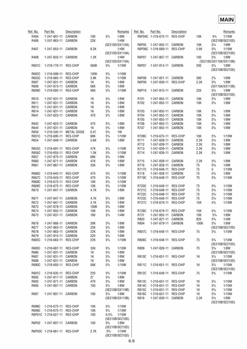
6-9
MAIN
Ref. No. Part No. Description Remarks Ref. No. Part No. Description RemarksR404 1-247-807-11 CARBON 100 5% 1/8WR406 1-247-863-11 CARBON 22K 1/4W
(SE210D/SX110A)R407 1-247-853-11 CARBON 8.2K 1/4W
(SE210D/SX110A)R408 1-247-833-11 CARBON 1.2K 1/4W
(SE210D/SX110A)R601C 1-218-770-11 RES-CHIP 560K 5% 1/10W
R602C 1-216-699-11 RES-CHIP 100K 5% 1/10WR603C 1-216-665-11 RES-CHIP 3.9K 5% 1/10WR607 1-247-831-11 CARBON 1K 5% 1/8WR608 1-247-873-11 CARBON 56K 5% 1/8WR609C 1-216-693-11 RES-CHIP 56K 5% 1/10W
R610 1-247-831-11 CARBON 1K 5% 1/8WR611 1-247-831-11 CARBON 1K 5% 1/8WR613 1-247-831-11 CARBON 1K 5% 1/8WR614 1-247-831-11 CARBON 1K 5% 1/8WR641 1-247-823-11 CARBON 470 5% 1/8W
R642 1-247-823-11 CARBON 470 5% 1/8WR644 1-247-831-11 CARBON 1K 5% 1/8WR650 1-216-345-11 METAL OXIDE 0.47 5% 1WR651C 1-216-695-11 RES-CHIP 68K 5% 1/10WR654 1-247-849-11 CARBON 5.6K 5% 1/8W
R655C 1-216-691-11 RES-CHIP 47K 5% 1/10WR656C 1-216-655-11 RES-CHIP 1.5K 5% 1/10WR657 1-247-875-11 CARBON 68K 5% 1/8WR660 1-247-871-11 CARBON 47K 5% 1/8WR661 1-247-867-11 CARBON 33K 5% 1/8W
R666C 1-216-643-11 RES-CHIP 470 5% 1/10WR667C 1-216-643-11 RES-CHIP 470 5% 1/10WR668C 1-216-675-11 RES-CHIP 10K 5% 1/10WR669C 1-216-675-11 RES-CHIP 10K 5% 1/10WR670 1-247-847-11 CARBON 4.7K 5% 1/8W
R671 1-247-847-11 CARBON 4.7K 5% 1/8WR672 1-247-847-11 CARBON 4.7K 5% 1/8WR673 1-247-879-11 CARBON 100K 5% 1/8WR674 1-247-855-11 CARBON 10K 5% 1/8WR675 1-247-837-11 CARBON 180 5% 1/4W
R676 1-247-866-11 CARBON 30K 5% 1/8WR677 1-247-863-11 CARBON 22K 5% 1/8WR678 1-247-863-11 CARBON 22K 5% 1/8WR679 1-247-815-11 CARBON 220 5% 1/8WR682C 1-216-683-11 RES-CHIP 22K 5% 1/10W
R685C 1-216-687-11 RES-CHIP 33K 5% 1/10WR686 1-247-831-11 CARBON 1K 5% 1/8WR687 1-247-831-11 CARBON 1K 5% 1/8WR688 1-247-831-11 CARBON 1K 5% 1/8WR690C 1-216-693-11 RES-CHIP 56K 5% 1/10W
R691C 1-216-635-11 RES-CHIP 220 5% 1/10WR692 1-247-817-11 CARBON 27 5% 1/8WR693 1-247-871-11 CARBON 47K 5% 1/8WR695 1-247-807-11 CARBON 100 5% 1/8W
(SE210B/SX110B)R697 1-247-807-11 CARBON 100 5% 1/8W
(SE210B/SX110B)
R698C 1-216-675-11 RES-CHIP 10K 5% 1/10WR699C 1-216-675-11 RES-CHIP 10K 5% 1/10WR6P01C 1-216-627-11 RES-CHIP 100 0.5% 1/10W
(SE210B/SE210D)R6P02 1-247-807-11 CARBON 100 5% 1/8W
(SE210B/SE210D)R6P03C 1-216-661-11 RES-CHIP 2.7K 5% 1/10W
(SE210B/SE210D)
R6P04C 1-216-675-11 RES-CHIP 10K 5% 1/10W(SE210B/SE210D)
R6P05 1-247-855-11 CARBON 10K 5% 1/8WR6P06C 1-216-669-11 RES-CHIP 5.6K 5% 1/10W
(SE210B/SE210D)R6P07 1-247-807-11 CARBON 100 5% 1/8W
(SE210G/SX110A/SX110B)R6P07 1-247-814-11 CARBON 200 5% 1/8W
(SE210B/SE210D)
R6P08 1-247-821-11 CARBON 390 2% 1/8WR6P09 1-247-839-11 RES-CHIP 2.2K 5% 1/8W
(SX110A/SX110B)R6P10 1-247-815-11 CARBON 220 5% 1/8W
(SE210B/SE210D)R701 1-247-855-11 CARBON 10K 5% 1/8WR702 1-247-855-11 CARBON 10K 5% 1/8W
R703 1-247-855-11 CARBON 10K 5% 1/8WR704 1-247-855-11 CARBON 10K 5% 1/8WR705 1-247-855-11 CARBON 10K 5% 1/8WR706 1-247-855-11 CARBON 10K 5% 1/8WR707 1-247-855-11 CARBON 10K 5% 1/8W
R708C 1-216-675-11 RES-CHIP 10K 5% 1/10WR711 1-247-839-11 CARBON 2.2K 5% 1/8WR712 1-247-839-11 CARBON 2.2K 5% 1/8WR713 1-247-839-11 CARBON 2.2K 5% 1/8WR714 1-247-839-11 CARBON 2.2K 5% 1/8W
R715 1-247-839-11 CARBON 2.2K 5% 1/8WR716 1-247-828-11 CARBON 75 5% 1/8WR717C 1-216-648-11 RES-CHIP 75 5 1/10WR718 1-247-828-11 CARBON 75 5% 1/8WR719C 1-216-648-11 RES-CHIP 75 5% 1/10W
R720C 1-216-648-11 RES-CHIP 75 5% 1/10WR721C 1-216-648-11 RES-CHIP 75 5% 1/10WR722C 1-216-648-11 RES-CHIP 75 5% 1/10WR723C 1-216-648-11 RES-CHIP 75 5% 1/10WR727C 1-216-679-11 RES-CHIP 15K 5% 1/10W
R728C 1-216-679-11 RES-CHIP 15K 5% 1/10WR731 1-247-855-11 CARBON 10K 5% 1/8WR803 1-247-821-11 CARBON 820 5% 1/4WR804 1-247-879-11 CARBON 100K 5% 1/8W
(SE210B/SE210D)R807C 1-216-648-11 RES-CHIP 75 5% 1/10W
R808C 1-216-648-11 RES-CHIP 75 5% 1/10W(SE210B/SE210D)
R809 1-247-828-11 CARBON 75 5% 1/8W(SE210B/SE210D)
R810C 1-216-651-11 RES-CHIP 1K 5% 1/10W(SE210B/SE210D)
R811C 1-216-651-11 RES-CHIP 1K 5% 1/10W(SE210B/SE210D)
R812C 1-216-648-11 RES-CHIP 75 5% 1/10W
R813C 1-216-651-11 RES-CHIP 1K 5% 1/10WR814C 1-216-651-11 RES-CHIP 1K 5% 1/10WR815C 1-216-651-11 RES-CHIP 1K 5% 1/10WR816C 1-216-651-11 RES-CHIP 1K 5% 1/10WR818 1-247-839-11 CARBON 2.2K 5% 1/8W
(SE210B/SE210D)
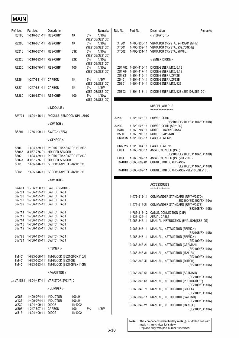
6-10
MAIN
Ref. No. Part No. Description Remarks Ref. No. Part No. Description RemarksR819C 1-216-651-11 RES-CHIP 1K 5% 1/10W
(SE210B/SE210D)R820C 1-216-651-11 RES-CHIP 1K 5% 1/10W
(SE210B/SE210D)R821C 1-216-687-11 RES-CHIP 33K 5% 1/10W
(SE210B/SE210D)R822C 1-216-683-11 RES-CHIP 22K 5% 1/10W
(SE210B/SE210D)R823C 1-218-776-11 RES-CHIP 100 5% 1/10W
(SE210B/SE210D)
R826 1-247-831-11 CARBON 1K 5% 1/8W(SE210B/SE210D)
R827 1-247-831-11 CARBON 1K 5% 1/8W(SE210B/SE210D)
R828C 1-216-627-11 RES-CHIP 100 5% 1/10W(SE210B/SE210D)
< MODULE >
RM701 1-804-446-11 MODULE-REMOCON GP1U291Q
< SWITCH >
RS601 1-786-199-11 SWITCH (REC)
< SENSOR >
S601 1-804-439-11 PHOTO-TRANSISTOR PT493FS601A 3-067-776-01 HOLDER-SENSORS602 1-804-439-11 PHOTO-TRANSISTOR PT493FS602A 3-067-776-01 HOLDER-SENSORSC01 7-685-646-11 SCREW-TAPTITE +BVTP 3x8
SC02 7-685-646-11 SCREW-TAPTITE +BVTP 3x8
< SWITCH >
SW601 1-786-198-11 SWITCH (MODE)SW701 1-786-195-11 SWITCH TACTSW703 1-786-195-11 SWITCH TACTSW708 1-786-195-11 SWITCH TACTSW709 1-786-195-11 SWITCH TACT
SW711 1-786-195-11 SWITCH TACTSW712 1-786-195-11 SWITCH TACTSW714 1-786-195-11 SWITCH TACTSW718 1-786-195-11 SWITCH TACTSW719 1-786-195-11 SWITCH TACT
SW723 1-786-195-11 SWITCH TACTSW724 1-786-195-11 SWITCH TACT
< TUNER >
TM401 1-693-550-11 TM-BLOCK (SE210D/SX110A)TM401 1-693-552-11 TM-BLOCK (SE210G)TM401 1-693-553-11 TM-BLOCK (SE210B/SX110B)
< VARISTOR >
0VA1SS1 1-804-437-11 VARISTOR SVC471D
< JUMPER >
W067 1-400-074-11 INDUCTOR 100uHW136 1-400-074-11 INDUCTOR 100uHW230 1-804-409-11 DIODE 1N4002W505 1-247-807-11 CARBON 100 5% 1/8WW513 1-804-409-11 DIODE 1N4002
< VIBRATOR >
XT301 1-795-330-11 VIBRATOR CRYSTAL (4.433619MHZ)XT601 1-795-332-11 VIBRATOR CRYSTAL (32.768KHz)XT602 1-795-331-11 VIBRATOR CRYSTAL (8MHz)
< ZENER DIODE >
ZD1P02 1-804-416-11 DIODE-ZENER MTZJ5.1BZD1P04 1-804-417-11 DIODE-ZENER MTZJ9.1BZD1SS1 1-804-415-11 DIODE-ZENER UZP43BZD401 1-804-414-11 DIODE-ZENER UZP33BZD801 1-804-418-11 DIODE-ZENER MTZJ12B
ZD802 1-804-418-11 DIODE-ZENER MTZJ12B (SE210B/SE210D)
MISCELLANEOUS**************
0200 1-823-023-11 POWER-CORD (SE210B/SE210D/SX110A/SX110B)
0200 1-823-025-11 POWER-CORD (SE210G)B410 1-763-704-11 MOTOR-LOADING ASSYB560 1-763-703-11 MOTOR-CAPSTANCN3A1S 1-823-022-11 CABLE-FLAT 6P
CN602S 1-823-164-11 CABLE-FLAT 7PG001 1-763-706-11 ASSY-CYLINDER (PAL)
(SE210B/SE210D/SX110A/SX110B)G001 1-763-707-11 ASSY-CYLINDER (PAL)(SE210G)TM401B 3-066-699-01 CONNECTOR BOARD-ASSY
(SE210G/SX110A/SX110B)TM401B 3-066-699-11 CONNECTOR BOARD-ASSY (SE210B/SE210D)
ACCESSORIES************
1-476-516-11 COMMANDER STANDARD (RMT-V257D)(SE210D/SE210G/SX110A)
1-476-516-21 COMMANDER STANDARD (RMT-V257E)(SE210B/SX110B)
1-783-213-12 CABLE, CONNECTION (21P)1-823-126-11 AERIAL CABLE3-066-346-11 MANUAL INSTRUCTION (ENGLISH)(SE210G)
3-066-347-11 MANUAL, INSTRUCTION (FRENCH)(SE210B/SX110B)
3-066-348-11 MANUAL, INSTRUCTION (FRENCH)(SE210D/SX110A)
3-066-348-21 MANUAL, INSTRUCTION (GERMAN)(SE210D/SX110A)
3-066-348-31 MANUAL, INSTRUCTION (ITALIAN)(SE210D/SX110A)
3-066-348-41 MANUAL, INSTRUCTION (DUTCH)(SE210D/SX110A)
3-066-348-51 MANUAL, INSTRUCTION (SPANISH)(SE210D/SX110A)
3-066-348-61 MANUAL, INSTRUCTION (PORTUGUESE)(SE210D/SX110A)
3-066-348-71 MANUAL, INSTRUCTION (GREEK)(SE210D/SX110A)
3-066-349-11 MANUAL, INSTRUCTION (SWDISH)(SE210D/SX110A)
3-066-349-21 MANUAL, INSTRUCTION (DANISH)(SE210D/SX110A)
Note: The components identified by matk ! or dotted line withmark ! are critical for safety.Replace only with part number specified
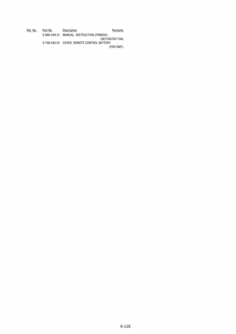
6-11E
Ref. No. Part No. Description Remarks3-066-349-31 MANUAL, INSTRUCTION (FINNISH)
(SE210D/SX110A)3-709-433-01 COVER, REMOTE CONTROL BATTERY
(FOR RMT)

– 68 –
Sony CorporationNetwork Entertainment Group
SLV-SE210B/SE210D/SE210G/SX110A/SX110B
9-921-793-112001C1600-1
© 2001.3Published by Quality Assurance Dept.


![Video Cassette Recorder · 2019. 2. 1. · 2 ADVERTENCIA Master Page : Left filename[010WAR.fm] model name1[SLV-SE310D] model name2[SLV-SE510D] [3-065-669-21 (1)] ADVERTENCIA Para](https://static.fdocuments.net/doc/165x107/613e2fd059df642846165dff/video-cassette-recorder-2019-2-1-2-advertencia-master-page-left-filename.jpg)