Rio-Eco/Rio-Eco Z - Comercial Naval...
16
Rio-Eco Rio-Eco Z Tele-Monitor Pump Catalogue Booklet 1137.178/2-10 Rio-Eco/Rio-Eco Z High-efficiency circulators with continuously variable differential pressure control and IR interface for remote control Applications F Hot-water heating systems F Heat recovery systems F Cooling circuits in air-conditioning systems Fluid Pumped Clean water and/or water treated in accordance with the rel- evant regulations, not containing aggressive, abrasive or solid substances. Water treated with commercial antifreeze agents based on gly- cols (mixture ratio max. 1 : 1) with inhibitors (antirust). If the gly- col content equals or exceeds 20 %, the operating data must be checked and verified. Heating water in accordance with VDI 2035. Operating Data Screw-ended pumps Flanged pumps Rp 1 1 / 4 DN 32 to 65 Q up to 10 m 3 /h, 2.8 l/s up to 44 m 3 /h, 12 l/s 1 ) H up to 12 m up to 13 m P 1 up to 290 W up to 620 W p 10 bar 10 bar t - 10 °C to +110 °C - 10 °C to +110 °C Ambient temperature: max. +40 °C 1 ) if operated in parallel Designation Rio Eco (Z) 50 - 80 Type series High-efficiency pump Twin pump Nominal diameter in mm Head in m x 10 (example 100 = 10 m) Design Rio-Eco: Maintenance-free wet rotor pump (glandless), flanged or screw-ended, with integrated frequency inverter for continuously variable differential pressure control. IR (infra-rot) interface for remote control. LON bus interface can be retrofitted. - Graphical display - Full motor protection with integrated trip electronics - Volt-free contacts for general fault reporting - Automatic night-time operation - Interface for communication modules Rio-Eco Z: Rio-Eco twin pump model for stand-by operation (integrated swing check valve) or additional pump start-up in case of peak load (parallel operation) Control modes: - ∆p-c for constant differential pressure at the pump - ∆p-c for variable differential pressure at the pump - ∆p-c for temperature-governed differential pressure at the pump Bearings Special plain bearings lubricated by the fluid pumped. Materials Volute casing cast iron EN-GJL-250 2 ) DN 30 EN-GJL-200 3 ) Shaft chrome steel X 40 Cr 13 Impeller glass fibre reinforced polypropylene Bearings special carbon, metal-impregnated 2 ) to EN 1561 (was GG-25) 3 ) to EN 1561 (was GG-20) Drive EC motor, IP 44, thermal class F Connection to power supply Rio-Eco/Rio-Eco Z: 1~230 V, 50 Hz interference suppression class B
Transcript of Rio-Eco/Rio-Eco Z - Comercial Naval...

Rio-Eco Rio-Eco Z Tele-Monitor
Pump Catalogue Booklet1137.178/2-10 Rio-Eco/Rio-Eco Z
High-efficiency circulatorswith continuously variable differential pressure control
and IR interface for remote control
Applications Hot-water heating systems Heat recovery systems Cooling circuits in air-conditioning systems
Fluid PumpedClean water and/or water treated in accordance with the rel-evant regulations, not containing aggressive, abrasive or solidsubstances.Water treated with commercial antifreeze agents based on gly-cols (mixture ratio max. 1 : 1) with inhibitors (antirust). If the gly-col content equals or exceeds 20 %, the operating data must bechecked and verified.Heating water in accordance with VDI 2035.
Operating DataScrew-ended pumps Flanged pumps
Rp 1 1/4 DN 32 to 65Q up to 10 m3/h, 2.8 l/s up to 44 m3/h, 12 l/s 1)H up to 12 m up to 13 mP1 up to 290 W up to 620 Wp 10 bar 10 bart -10 °C to +110 °C -10 °C to +110 °CAmbient temperature: max. +40 °C
1) if operated in parallel
Designation Rio Eco (Z) 50 - 80
Type seriesHigh-efficiency pumpTwin pumpNominal diameter in mmHead in m x 10 (example 100 = 10 m)
DesignRio-Eco: Maintenance-free wet rotor pump (glandless),flanged or screw-ended, with integrated frequency inverter forcontinuously variable differential pressure control.IR (infra-rot) interface for remote control.LON bus interface can be retrofitted.- Graphical display- Full motor protection with integrated trip electronics- Volt-free contacts for general fault reporting- Automatic night-time operation- Interface for communication modulesRio-Eco Z: Rio-Eco twin pump model for stand-by operation(integrated swing check valve) or additional pump start-up incase of peak load (parallel operation)Control modes:- ∆p-c for constant differential pressure at the pump- ∆p-c for variable differential pressure at the pump- ∆p-c for temperature-governed differential pressure at the
pump
BearingsSpecial plain bearings lubricated by the fluid pumped.
MaterialsVolute casing cast iron EN-GJL-250 2)
DN 30 EN-GJL-200 3)Shaft chrome steel X 40 Cr 13Impeller glass fibre reinforced polypropyleneBearings special carbon, metal-impregnated2) to EN 1561 (was GG-25)3) to EN 1561 (was GG-20)
DriveEC motor, IP 44, thermal class FConnection to power supplyRio-Eco/Rio-Eco Z: 1~230 V, 50 Hz
interference suppression class B

Rio-Eco
Rio-Eco Z
Rio-Eco Z
Rio-EcoRio-Eco Z
2
Selection Chart Single Pumps
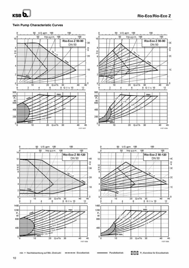
Selection Chart Twin PumpsThe characteristic curves refer to parallel operation of both pumps.

Reduction in logistics and storage costs- Flexible installation options thanks to
PN 6 / PN 10 adapter (oval bolt hole)flange.
Ease of installation and handling- Optimum access to flanges and flexible
arrangement of the electronics module- Integrated general fault reporting by
volt-free contacts- Pump casing with standard heat insulation
equipment- Integrated LC display
Energy-efficient- Maintenance-free glandless pump with EC motor of new
high-efficiency design helps reduce energy costs by upto 80 % compared with fixed speed circulators.
- The suction neck liner between impeller and pumpcasing reduces the clearance gap width.
- The non-metallic can reduces eddy current losses.- The plastic impeller with multiply curved vanes ensures
high efficiency.- The cataphoretic coating makes for smooth surfaces in
the pump casing.
Universal use- All-round pump for the entire range of heating,
ventilation and air-conditioning applications from -10 to +110 °C
- Continuously variable speed adjustment and variouscontrol modes:- ∆p-c for constant differential pressure at the pump- ∆p-c for variable differential pressure at the pump- ∆p-c for temperature-governed differential
pressure at the pump- Automatic night-time operation
Rio-Eco/Rio-Eco Z
3
Minimum PressureMinimum pressure pmin at the pump suction nozzle to avoidcavitation noise at an ambient temperature of +40 °C and apumped-water temperature of max.:
The values are applicable up to 300 m above sea level. For installation heights >300 m, an allowance of +0.01 bar/100m must be added.
t 50 oC 95 oC 110 oC
pminRio-Eco/Rio-Eco Z bar bar bar
30-12032-12040-8040-12050-8050-9050-12065-90
0,050,050,050,050,050,050,050,05
0,50,50,50,50,50,50,50,5
1,11,11,11,11,11,11,11,1

min. = Night-time operation at minimum speed
Rio-Eco/Rio-Eco Z
4
Single Pump Characteristic Curves

min. = Night-time operation at minimum speed
Rio-Eco/Rio-Eco Z
5
Single Pump Characteristic Curves
min. = Night-time operation at minimum speed
Rio-Eco/Rio-Eco Z
6
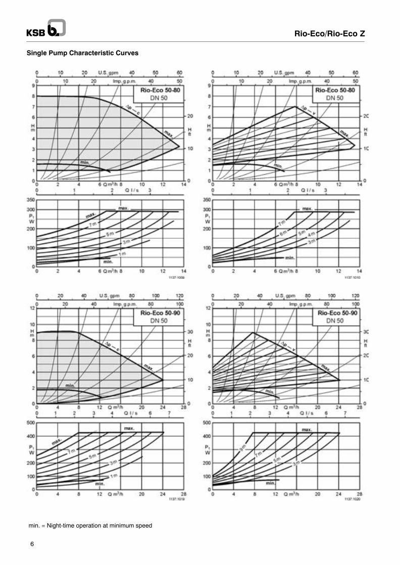
Single Pump Characteristic Curves
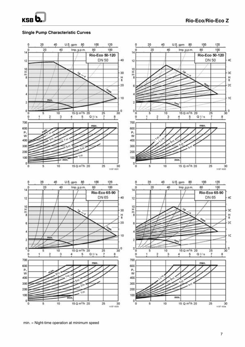
min. = Night-time operation at minimum speed
Rio-Eco/Rio-Eco Z
7
Single Pump Characteristic Curves

Rio-Eco/Rio-Eco Z
8
Twin Pump Characteristic Curves

Rio-Eco/Rio-Eco Z
9
Twin Pump Characteristic Curves
Rio-Eco/Rio-Eco Z
10
Twin Pump Characteristic Curves

Mot
or
Sig
nalli
ngco
ntac
ts
prot
ectio
n
Rio-Eco/Rio-Eco Z
11
Technical Data
Rio-Eco DNRp
Speed P1 P2 max Rated current
Max. permissible operating pressure 10 bar
1/min W W A kg
30-12032-12040-8040-12050-8050-9050-12065-90
1 1/432405050505065
1600 - 48001600 - 48001800 - 48001400 - 46001800 - 48001400 - 41001400 - 46001400 - 4600
18 - 29018 - 29018 - 29021 - 45018 - 29021 - 43021 - 62021 - 620
200200200350200350500500
SSMSSMSSMSSMSSMSSMSSMSSM
0.18 - 1.320.18 - 1.320.18 - 1.320.16 - 2.010.18 - 1.320.16 - 1.880.16 - 2.700.16 - 2.70
29 130 53429 130 53529 130 53629 130 54129 130 53729 130 54229 130 54329 130 544
6.08.59.5
14.011.515.515.517.0
Rio-Eco Z
Z 32-120Z 40-80Z 40-120Z 50-80Z 50-90Z 50-120
324040505050
1600 - 48001800 - 48001400 - 46001800 - 48001400 - 41001400 - 4600
18 - 29018 - 29021 - 45018 - 29021 - 43021 - 620
200200350200350500
SSMSSMSSMSSMSSMSSM
0.18 - 1.320.18 - 1.320.16 - 2.010.18 - 1.320.16 - 1.880.16 - 2.70
29 130 53829 130 53929 130 54529 130 54029 130 54629 130 547
15.016.024.718.027.027.0
1) = integrated motor protection in the terminal boxSSM = general fault reporting
Pipe ConnectionFlanged pumps fitted with an adapter flange (oval bolt hole pat-tern) can be connected to PN 6 and PN 16 mating flanges toDIN or DIN EN up to nominal diameters of DN 65. Adapterflanges of this type cannot be connected with other adapterflanges. Use bolts of property class 4.6 or higher for the flangeconnections. The washers included in the scope of supply mustbe fitted between the bolt / nut head and the adapter (oval bolthole) flange.
Recommended bolt lengths:
Thread Tightening Min. bolt lengthg gtorque DN 32/DN 40 DN 50/DN 65
PN 6 flanged connection
M 12 40 Nm 55 mm 60 mm
PN 10 flanged connection
M 16 95 Nm 60 mm 65 mm
Flange Dimensions
Adapterfl
ØkL1/kL2 n x dL1/dL2pflange ØD Ød PN 6 PN 10 PN 6 PN 10
DN 32 140 78 90 100 4 x Ø14 4 x Ø19
DN 40 150 88 100 110 4 x Ø14 4 x Ø19
DN 50 165 102 110 125 4 x Ø14 4 x Ø19
DN 65 185 122 130 145 4 x Ø14 4 x Ø19
Permissible Installation Positions
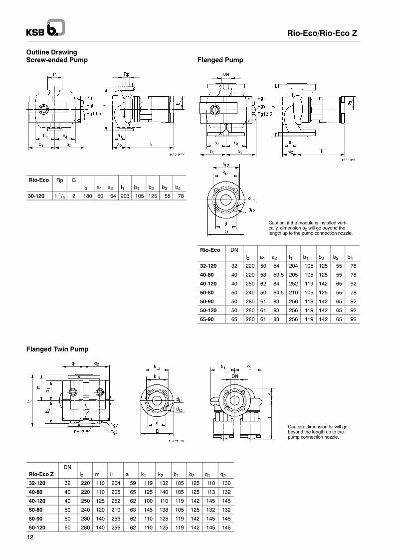
Caution: if the module is installed verti-cally, dimension b2 will go beyond thelength up to the pump connection nozzle.
Caution: dimension b2 will gobeyond the length up to thepump connection nozzle.
Rio-Eco/Rio-Eco Z
12
Outline DrawingScrew-ended Pump
Rio-Eco Rp Gpl0 a1 a2 l1 b1 b2 b3 b4
30-120 1 1/4 2 180 50 54 203 105 125 55 78
Flanged Pump
Rio-Eco DNl0 a1 a2 l1 b1 b2 b3 b4
32-120 32 220 50 54,0 204 105 125 55 78
40-80 40 220 53 59.5 205 105 125 55 78
40-120 40 250 62 84,0 252 119 142 65 92
50-80 50 240 50 64.5 210 105 125 55 78
50-90 50 280 61 83,0 256 119 142 65 92
50-120 50 280 61 83,0 256 119 142 65 92
65-90 65 280 61 83,0 256 119 142 65 92
Flanged Twin Pump
DNRio-Eco Z l0 m l1 a k1 k2 b1 b2 q1 q2
32-120 32 220 110 204 59 119 132 105 125 110 130
40-80 40 220 110 205 65 125 140 105 125 113 132
40-120 40 250 125 252 62 100 110 119 142 145 145
50-80 50 240 120 210 63 145 138 105 125 132 132
50-90 50 280 140 256 62 110 125 119 142 145 145
50-120 50 280 140 256 62 110 125 119 142 145 145

PC
P m
odul
e
LON
mod
ule
Ext
.Off
mod
ule
SB
M m
odul
e
Ext
.Min
mod
ule
Rio-Eco/Rio-Eco Z
13
Modules and Accessories
Description for pump seriesRio-Eco / Rio-Eco Z
Ident. No. kg
Process control processor (PCP) module (retrofittable)- with PCP interface for
connection to the digital building management system
X 01 081 036 0.2
LON module (retrofittable)- with LON interface
X 01 081 037 0.2
Ext.Off module (retrofittable)- with control input for Pump OFF- with control output 0...10 V for remote
setting of speed or set point
X 01 081 038 0.2
Ext.Min module (retrofittable)- with control input for Minimum speed- with control output 0...10 V for remote
setting of speed or set point
X 01 081 039 0.2
SBM module (retrofittable)- for general In operation message- with control output 0...10 V for remote
setting of speed or set point
X 01 081 040 0.2
Tele-Monitor- Remote control for Rio Eco / Rio Eco Z
with infrared interface (IR)- Start-up and
diagnostic instrument / tool- Extension of pump functions- Direction-of-rotation verification instrument
for all pumps and standardized motors
X 01 054 714 0.4
The following combination options and functions are available for twin pump management:
Module type
Function 1)
Serial digital PCP interface for connection to the building management system(BMS) via KSB interface converter or coupler modules provided on site
1xMA1xSL
Serial digital LON interface for connection to LON/Works networks, FTT 10 A transceiver
1xSL 1xMA
Input for volt-free NC contact enabling the Ext.Off function 2)0...10 V control input for remote setting of speed or set point 3)
1xSL 1xMA
Input for volt-free NC contact enabling the Ext.Min function 4)0...10 V control input for remote setting of speed or set point 3)
1xSL 1xMA
SBM general In operation message via volt-free NO contact 5)0...10 V control input for remote setting of speed or set point 3)
1xMA1xSL
MA = Master, SL = Slave1) The control functions govern the entire twin pump set.
The control functions are enabled at the twin pumps master.The twin pumps slave receives the master pumps command via the modules DP interface (2-core connection cable).
2) None of the drives runs.3) The 0...10 V control input has various additional functions, see table on page 15.4) The base load pump runs at minimum speed; the other drive does not run.5) The general In operation message at the master shows when either one drive is running or when both drives are running.

Rio-Eco/Rio-Eco Z
14
Functions of the 0...10 V analog input for twin pump management
Twin pumpcontrol mode
Duty / Stand-by mode Parallel operation
Functions 0...10 V
Remote setting of speed (DDC)0...1 V: Off1...3 V: Min. speed3...10 V: nmin...nmax
- The base load pumps speed is set in line with the voltage signal.
- Base load pump change-over after 24 operating hours
- Both pumps run at the same speed set in line with the voltage signal.
Remote setting of set point0...1 V: Hmin1...10 V: Hmin...Hmax
- Base load pump controls differential pressure
- Base load pump change-over after 24 operating hours
- Peak load pump is started and stopped as required for optimum efficiency
- Base load pump change-over after 24 operating hours
If the Ext.Off and Ext.Min functions are to be available in addition via volt-free contacts, an analog interface converter and 2 PCP modules are required.All functions are then available at the interface converter (analog).
Technical Data of the Tele-Monitor
Enclosure IP 43Vibration fatigue limit IEC 68-2-6Operating temperature -10 °C to 40 °CBearing temperature -20 °C to 70 °CTransmitting and receiving range max. 10 mDisplay 50 x 50 mm, can be back-lit
Voltage supply 2 mignon alkaline cells (included in the scope of supply)
Battery life approx. 24 hours when switchedon and back-lit
Permanent buffering EE-PromGeneric emission standard EN 50081-1Generic immunity standard EN 50082-2
Functional Description of the Tele-Monitor
Communication Menu Automatic connection between pump and Tele-Monitor via infrared interface(manual coding of the pumps is not required)
Display Menu Display of the pumps actual data- Type- Set point ∆p, actual ∆p value- Flow rate- Set-point speed, actual speed- Power input- Modes of operation (∆p-c, ∆p-v, ∆p-T, On/Off, ...)- Fault reporting
Operation Menu Changing the mode of operation and set point- Control mode (∆p-c, ∆p-v, ∆p-T, ...)- Set point (∆p, speed)- On/Off
Statistics Menu Analysis of the pumps load profile- Histograms of the actual electrical and hydraulic values of an operating
cycle- Operating hours and operating data counter
Service Menu - Fault diagnosis- Fault statistics- Functional testing of pump- Functional testing of monitor- Functional testing of connection via PCP interface- Direction-of-rotation check (for all pumps and standardized motors)
Customization Menu Customization of the Tele-Monitors- Dialogue language selection- Display contrast- Automatic cut-out (time-out)- Personal password- Default settings for automatic pump set-up at the push of a button

Rio-Eco/Rio-Eco Z
15
Wiring Diagram
Connection to power supplyA.c. motor 1~230 V, 50 Hz
DP = Interface for twin pump management
PLR = Interface for PCP bus
LON = Interface for LON bus
0...10 V = remote setting of set point or speed
Ext.Off 1) = External volt-free NC contact- Closed: Pump enabled- Open: Pump OFF
Ext.Min 1) = External volt-free NC contact- Closed: Pump enabled- Open: Pump OFF
SBM = General In operation message (NO contact, 1 A, 250 V~)
1) Terminals are bridged on pump sets leaving the factory.
Standard
PCP Module LON Module Ext.off Module Ext.min Module SBM Module
not used not used

1137
.178
/2-1
0 /
1.1
1.20
03S
ubje
ct to
tech
nica
l mod
ifica
tions
with
out p
rior
notic
e.
Rio-Eco/Rio-Eco Z
Technical Data
Process control processor (PCP) module:Terminal cross-section 0.25 1.0 mm2
Max. cable length 500 m
LON module:Transceiver FTT 10 AVoltage supply 5 V=/15 V= via the pumpCurrent requirement 30 mATerminal cross-section 0.25 1.0 mm2
Bus cable min 2x 0.34 mm2, twisted pair (10 t/m),unshielded (for ex. J-Y(st)Y 2 x 2 x 0.8 mm2)
Neuron ID duplicate adhesive label with the bar code of the Neuron IDProtocol LONTalk
Ext.Off moduleContact rating 24 V DC, 10 mAElectric strength 250 V ACMax. cable length 100 mTerminal cross-section 1.0 mm2
Ext.Min module:Contact rating 24 V DC, 10 mAElectric strength 250 V ACMax. cable length 100 mTerminal cross-section 1.0 mm2
General In operation message SBM:Contact rating 250 V AC/1 AMax. cable length 100 mTerminal cross-section 1.0 mm2
Control input 0...10 VElectric strength 24 V=Input resistance of the voltage input >100 kΩAccuracy + 5 %Max. cable length 25 m (shielded)Terminal cross-section 1.0 mm2


![· PDF file1. I,II,III 1.1. I The Einstein equations of General Relativity T ik = R ik 1 2 g ikR = [R] ik = gjl[R] ijkl = gjl 1 4 ab ij cd kl R abcd can be written as gjl [R](https://static.fdocuments.net/doc/165x107/5a8771e67f8b9ac96a8dbd47/-iiiiii-11-i-the-einstein-equations-of-general-relativity-t-ik-r-ik-1-2-g.jpg)