
RinwallExample
18
Previous Issue: New Next Planned Update: 1 September, 2007 Page 1 of 1 Primary contact: Abu-Adas, Hisham on phone 874-6908 Best Practice SABP-005 31 August, 2002 Storage Tank Ringwall Foundation Design Document Responsibility: Onshore Structures Standards Committee Storage Tank Ringwall Foundation Design
Transcript of RinwallExample
Previous Issue: New Next Planned Update: 1 September, 2007 Page 1 of 1 Primary contact: Abu-Adas, Hisham on phone 874-6908
Best Practice
SABP-005 31 August, 2002 Storage Tank Ringwall Foundation Design
Document Responsibility: Onshore Structures Standards Committee
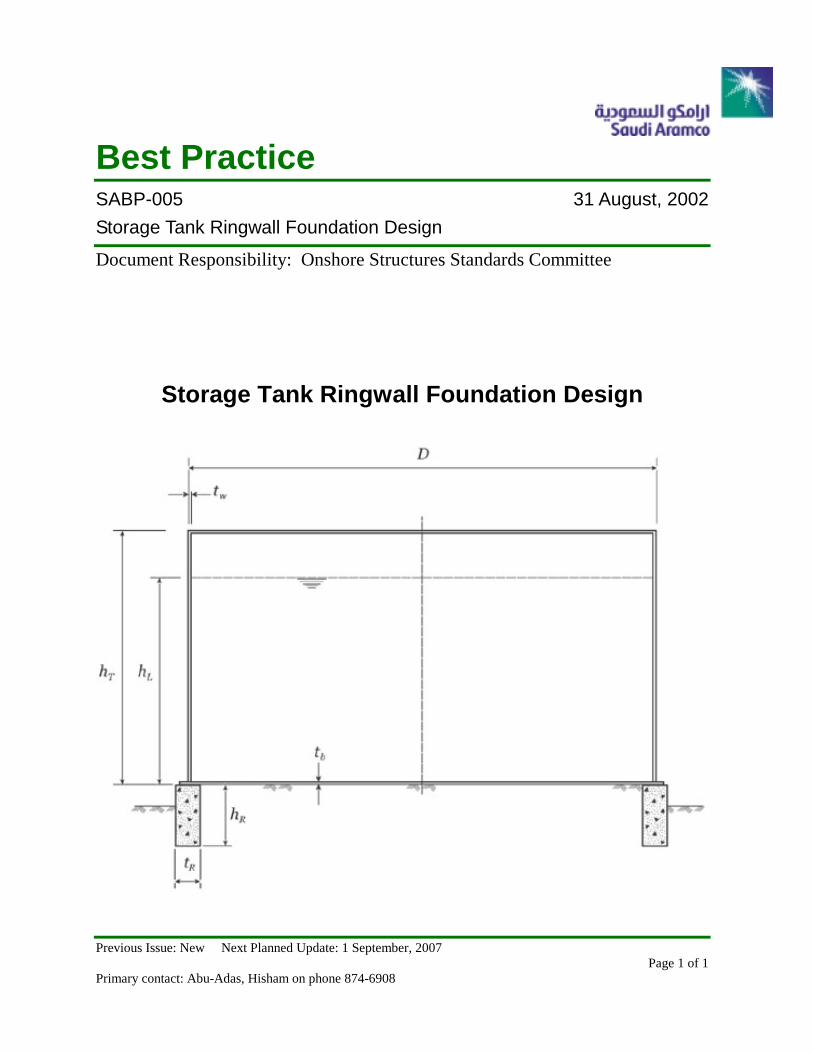
Storage Tank Ringwall Foundation Design
Document Responsibility: Civil SABP-005Issue Date: 31 August, 2002Next Planned Update: 1 September, 2007 Storage Tank Ringwall Foundation Design
Page 2 of 18
Strorage Tank Ringwall Foundation Design
Table of Contents
Page
1 Introduction ................................................................................................ 31.1 Purpose........................................................................................................ 3
1.2 Scope............................................................................................................ 3
1.3 Disclaimer ................................................................................................... 3
1.4 Conflicts with Mandatory Standards ....................................................... 3
2 References .................................................................................................. 42.1 Saudi Aramco Standards........................................................................... 4
2.2 Industry Codes and Standards. ................................................................ 4
3 General ........................................................................................................ 54 Design Conditions...................................................................................... 6
4.1 Vertical Loading......................................................................................... 6
4.2 Horizontal Loading .................................................................................... 6
5 Wind & Earthquake Stability and Pressures............................................ 65.1 Wind Stability............................................................................................. 6
5.2 Earthquake Stability.................................................................................. 7
5.3 Soil Bearing................................................................................................. 7
5.4 Settlement ................................................................................................... 7
5.5 Soil Pressure (No Uplift)............................................................................ 8
5.6 Soil Pressure (Uplift is Present) ................................................................ 8
6 Concrete Ring Wall Design ....................................................................... 96.1 Sizing ........................................................................................................... 9
6.2 Ringwall Thickness .................................................................................... 9
6.3 Ringwall Reinforcement ............................................................................ 9
7 Special Considerations............................................................................ 128 Anchor Bolts............................................................................................. 12
Attachment:Typical Storage Tank Ringwall Foundation Design – Example 1 .................... 13
Document Responsibility: Civil SABP-005Issue Date: 31 August, 2002Next Planned Update: 1 September, 2007 Storage Tank Ringwall Foundation Design
Page 3 of 18
1 Introduction
1.1 Purpose
The purpose of this practice is to provide the engineer and designer withguidelines for the analysis and design of storage tank ringwall foundations foruse by engineers working on Saudi Aramco projects and Saudi Aramcoengineers.
1.2 Scope
This design guide defines the minimum requirements for the analysis and designof storage tank ringwall foundations normally encountered in process industryfacilities at Saudi Aramco sites. It covers general design philosophy andrequirements to be used in the analysis and design of ring wall foundations.Section 2.0 of this instruction includes reference codes and Saudi Aramcostandards. General tank foundation information and recommendations arepresented, relevant design formulas are derived. In cases where this guidelineconflicts with these references, the conflict shall be immediately brought to theattention of the project engineer.
1.3 Disclaimer
The material in this Best Practices document provides the most correct andaccurate design guidelines available to Saudi Aramco which comply withinternational industry practices. This material is being provided for the generalguidance and benefit of the Designer. Use of the Best Practices in designingprojects for Saudi Aramco, however, does not relieve the Designer from hisresponsibility to verify the accuracy of any information presented or from hiscontractual liability to provide safe and sound designs that conform toMandatory Saudi Aramco Engineering Requirements. Use of the information ormaterial contained herein is no guarantee that the resulting product will satisfythe applicable requirements of any project. Saudi Aramco assumes noresponsibility or liability whatsoever for any reliance on the informationpresented herein or for designs prepared by Designers in accordance with theBest Practices. Use of the Best Practices by Designers is intended solely for,and shall be strictly limited to, Saudi Aramco projects. Saudi Aramco® is aregistered trademark of the Saudi Arabian Oil Company. Copyright, SaudiAramco, 2002.
1.4 Conflicts with Mandatory Standards
In the event of a conflict between this Best Practice and other Mandatory SaudiAramco Engineering Requirement, the Mandatory Saudi Aramco EngineeringRequirement shall govern.
Document Responsibility: Civil SABP-005Issue Date: 31 August, 2002Next Planned Update: 1 September, 2007 Storage Tank Ringwall Foundation Design
Page 4 of 18
2 References
This Best Practice is based on the latest edition of the references below, unlessotherwise noted. Short titles will be used herein when appropriate.
2.1 Saudi Aramco Standards
Saudi Aramco Engineering Standards (SAES)
SAES-A-112 Meteorological and Seismic Design Data
SAES-A-113 Geotechnical Engineering Requirements
SAES-A-114 Excavation and Backfill
SAES-A-204 Preparation of Structural Calculations
SAES-M-001 Structural Design Criteria for Non-BuildingStructures
SAES-Q-001 Criteria for Design and Construction of ConcreteStructures
SAES-Q-005 Concrete Foundations
Structural Design Best Practice
SABP-001 Anchor Bolt Design and Installation
2.2 Industry Codes and Standards
American Concrete Institute (ACI)
ACI 318 Building Code Requirements for ReinforcedConcrete and Commentary
American Society of Civil Engineers (ASCE)
ASCE 7 - 95 Minimum Design Loads for Buildings and OtherStructures
American Petroleum Institute (API)
API STD 650 Welded Steel Tanks for Oil Storage (incl.Appendices B, E & I)
3 General
3.1 The design and specifications for construction of storage tank ringwallfoundations shall be adequate for the structure intended use, in accordance withAppendix B of API STD 650 and commonly accepted engineering practice,
Document Responsibility: Civil SABP-005Issue Date: 31 August, 2002Next Planned Update: 1 September, 2007 Storage Tank Ringwall Foundation Design
Page 5 of 18
Saudi Aramco Engineering Standard SAES-Q-005 (Section 4.0), and thisguideline.
3.2 The types of storage tank normally encountered in industrial plants havecylindrical shells, essentially flat bottoms, and either cone roofs or floatingroofs. The height of these tanks generally does not exceed 60 feet and thediameter generally ranges from 10 feet to 360 feet.
3.3 Concrete ringwalls are used to help distribute heavy shell loads such as fromlarge dome roof tanks where the roof is supported entirely by shell. Concreteringwalls are also used when the tank must be anchored for internal pressure,earthquake, or wind loads.
3.4 Ringwall foundation design shall conform to this engineering guideline and toapplicable requirements of the soil report.
3.5 A geotechnical investigation is required for all new structures and foundationsas described in SAES-A-113. (Ref. SAES-Q-005, Para. 4.1.1).
3.6 The allowable soil bearing pressure shall be based on the results of thegeotechnical investigation, and a consideration of permissible total anddifferential settlements. Soil pressures shall be calculated under the action ofvertical and lateral loads using load combinations that result in the maximumsoil pressures. The maximum soil pressure shall not exceed the applicableallowable value. (Ref. SAES-Q-005, Para. 4.1.2).
3.7 Foundations shall be founded on either undisturbed soil or compacted fill. In thecase of foundations supported on compacted fill, the geotechnical investigationand/or SAES-A-114 shall govern the type of fill material and degree ofcompaction required. (Ref. SAES-Q-005, Para. 4.1.3).
3.8 In areas of firm soils, the following site preparation steps are recommended:
a) Strip the site of all topsoil and organic material.
b) Set the top of ringwall a minimum of 6 inches above finished gradeelevation to ensure adequate drainage. Coordinate this with piping group.
c) Slope interior tank pad surface to match tank bottom. A minimum of 1inch to 10 feet is recommended (taking into account settlement anddifferential settlement between the tank center and the ring wall) to ensureadequate tank drainage.
d) Provide a concrete ringwall to reduce differential settlement along thecircumference of the tank shell.
Document Responsibility: Civil SABP-005Issue Date: 31 August, 2002Next Planned Update: 1 September, 2007 Storage Tank Ringwall Foundation Design
Page 6 of 18
3.9 In areas of weak compressible soils, special foundations and design proceduresor soil improvement may be required to prevent failures or excessive settlement.Please refer to project soil investigation recommendations.
3.10 Ringwall depth below grade should be determined from allowable soil bearingpressures.
3.11 For tanks utilizing interior roof supports, the tank bottom shall be reinforced asrequired to distribute column loads and reduce local settlement.
3.12 When the tank diameter is less than 15 feet, the engineer should consider the useof a solid concrete octagon as opposed to a ringwall foundation.
3.13 The design and construction of all concrete foundations shall comply with therequirements of SAES-Q-001. (Ref. SAES-Q-005, Para. 4.3.1).
3.14 The design concrete compressive strength of concrete shall be 27.6 MPa(4000 psi) at 28 days. (Ref. SAES-Q-005, Para. 4.3.2.b).
4 Design Conditions
4.1 Vertical Loading
Vertical loads are considered in ringwall foundation design. Storage tankfoundations shall be designed to support the tank weight plus the weight ofstored product or water which is directly over the ringwall.
4.2 Horizontal Loading
Normally, horizontal loads are not considered in foundation design for storagetanks. However, tanks having a shell height greater than the diameter, the effectof high winds shall be considered and the foundations should be checked fornecessary anchor bolts. Wind loads shall be calculated in accordance with therequirements of SAES-A-112 and SAES-M-001 'Structural Design Criteria forNon-Building Structures" and ASCE 7 'Wind Load and Anchor Bolt Design forBuildings and Other Structures".
5 Wind & Earthquake Stability and Pressures
5.1 Wind Stability
Generally, wind stability is not a problem with storage tanks, however, if ht /D > 1,the stability should be checked. For an unanchored tank, the overturning momentfrom wind pressure shall not exceed two-thirds of the dead-load resisting moment,excluding any tank content, and shall be calculated as follows:
Document Responsibility: Civil SABP-005Issue Date: 31 August, 2002Next Planned Update: 1 September, 2007 Storage Tank Ringwall Foundation Design
Page 7 of 18
MO.T. ≤ 2/3 (WD/2)
where:
MO.T. = overturning moment from wind pressure, in foot-pounds
W = shell weight available to resist uplift, in pounds, less anycorrosion allowance, plus dead weight of any portion of roofsupported by the shell
D = tank diameter (ft)
For empty small high tanks, the resistance to sliding and overturning under theforce of wind should be checked.
If MO.T. > 2/3 (WD/2), anchor bolts are required. When anchors are required,the design tension load per anchor shall be calculated as follows:
tB = (4 MO.T.)/dN – W/N
where:
tB = design tension load per anchor, in pounds
d = diameter of anchor circle, in feet
N = number of anchors
Anchors shall be spaced a maximum of 10 feet apart.
5.2 Earthquake Stability
Seismic overturning moment in tank and shear forces shall be provided by thetank's vendor. The minimum safety factor against overturning and sliding shallbe 1.5. For seismic forces computations, refer to ASCE 7 and API STD 650.
5.3 Soil Bearing
In selecting the proper type of foundation, the bearing capacity of the soil is theprimary factor. A thorough knowledge of the soil properties is necessary toavoid excessive differential settlement and possible failure.
5.4 Settlement
Foundations on sandy soil shall be checked using weight of water sincesettlement under this condition occurs very rapidly and should be essentiallycomplete after the hydrotest weight (i.e., first loading). Foundations on claysoils shall be checked using the weight of the commodity (i.e., long termloading) because clay settles more evenly and slowly due to consolidation. In
Document Responsibility: Civil SABP-005Issue Date: 31 August, 2002Next Planned Update: 1 September, 2007 Storage Tank Ringwall Foundation Design
Page 8 of 18
some instances, it is advisable to use water test to consolidate clay layers byslowly filling the tank and waiting for settlement to occur.
5.5 Soil Pressure (No Uplift)
In considering soil-bearing pressure due to empty plus wind condition, there aretwo possible cases. In the first case, the foundation has no uplift (i.e., all of theringwall is bearing in compression). If there is no uplift, obviously maximumsoil pressure for empty plus wind will be less than the maximum soil pressurefor operating plus wind. Thus when there is no uplift, soil pressure for emptyplus wind does not need to be checked. The e / Do ratio can be used todetermine whether or not uplift is present. If uplift is not present, then:
qmin = P/A – MO.T. /Sxx ≥ 0
or e / Do ≤ Sxx / A Do
where:
Sxx = π (Do4 - Di
4) / 32 Do
A = π (Do² - Di²) / 4
Thus:
e / Do ≤ 0.125 {1 + (Di / Do)²}
or e / Do ≤ 0.20 for Di / Do ≥ 0.8
where:
Do = Ringwall outside diameter (ft)
Di = Ringwall inside diameter (ft)
e = Eccentricity (ft)
5.6 Soil Pressure (Uplift is Present)
If uplift is present (i.e., e/Do > 0.20), soil pressure should be calculated since themaximum pressure for empty plus wind could conceivably be higher thanoperating plus wind. In computing maximum pressure for a particular e/Doratio, two transcendental simultaneous equilibrium equations must be solved.Since uplift will seldom be of major consequence with storage tanks, no designcurves are developed to solve the two equilibrium equations. If e/Do > 0.33, theengineer may either increase hR or use another foundation type. However, donot increase tR to meet wind requirements.
Document Responsibility: Civil SABP-005Issue Date: 31 August, 2002Next Planned Update: 1 September, 2007 Storage Tank Ringwall Foundation Design
Page 9 of 18
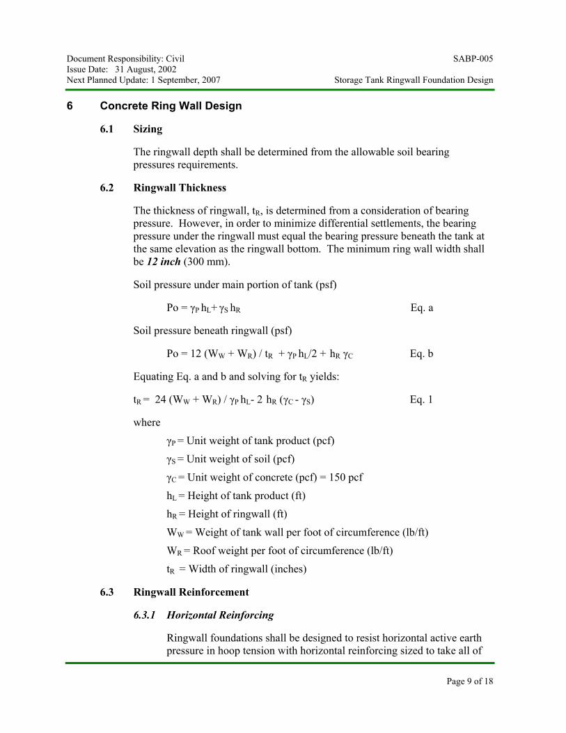
6 Concrete Ring Wall Design
6.1 Sizing
The ringwall depth shall be determined from the allowable soil bearingpressures requirements.
6.2 Ringwall Thickness
The thickness of ringwall, tR, is determined from a consideration of bearingpressure. However, in order to minimize differential settlements, the bearingpressure under the ringwall must equal the bearing pressure beneath the tank atthe same elevation as the ringwall bottom. The minimum ring wall width shallbe 12 inch (300 mm).
Soil pressure under main portion of tank (psf)
Po = γP hL+ γS hR Eq. a
Soil pressure beneath ringwall (psf)
Po = 12 (WW + WR) / tR + γP hL/2 + hR γC Eq. b
Equating Eq. a and b and solving for tR yields:
tR = 24 (WW + WR) / γP hL- 2 hR (γC - γS) Eq. 1
where
γP = Unit weight of tank product (pcf)
γS = Unit weight of soil (pcf)
γC = Unit weight of concrete (pcf) = 150 pcf
hL = Height of tank product (ft)
hR = Height of ringwall (ft)
WW = Weight of tank wall per foot of circumference (lb/ft)
WR = Roof weight per foot of circumference (lb/ft)
tR = Width of ringwall (inches)
6.3 Ringwall Reinforcement
6.3.1 Horizontal Reinforcing
Ringwall foundations shall be designed to resist horizontal active earthpressure in hoop tension with horizontal reinforcing sized to take all of
Document Responsibility: Civil SABP-005Issue Date: 31 August, 2002Next Planned Update: 1 September, 2007 Storage Tank Ringwall Foundation Design
Page 10 of 18
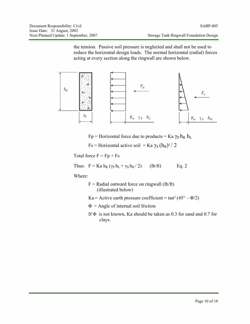
the tension. Passive soil pressure is neglected and shall not be used toreduce the horizontal design loads. The normal horizontal (radial) forcesacting at every section along the ringwall are shown below.
Fp = Horizontal force due to products = Ka γP hR hL
Fs = Horizontal active soil = Ka γS (hR)² / 2
Total force F = Fp + Fs
Thus: F = Ka hR (γP hL + γS hR / 2) (lb/ft) Eq. 2
Where:
F = Radial outward force on ringwall (lb/ft) (illustrated below)
Ka = Active earth pressure coefficient = tan² (45° – Φ/2)
Φ = Angle of internal soil friction
If Φ is not known, Ka should be taken as 0.3 for sand and 0.7 forclays.
Document Responsibility: Civil SABP-005Issue Date: 31 August, 2002Next Planned Update: 1 September, 2007 Storage Tank Ringwall Foundation Design
Page 11 of 18
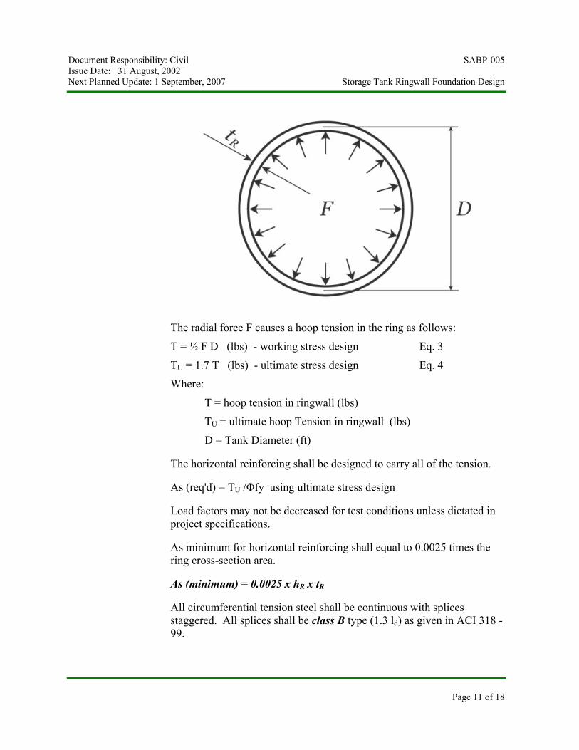
The radial force F causes a hoop tension in the ring as follows:
T = ½ F D (lbs) - working stress design Eq. 3
TU = 1.7 T (lbs) - ultimate stress design Eq. 4
Where:
T = hoop tension in ringwall (lbs)
TU = ultimate hoop Tension in ringwall (lbs)
D = Tank Diameter (ft)
The horizontal reinforcing shall be designed to carry all of the tension.
As (req'd) = TU /Φfy using ultimate stress design
Load factors may not be decreased for test conditions unless dictated inproject specifications.
As minimum for horizontal reinforcing shall equal to 0.0025 times thering cross-section area.
As (minimum) = 0.0025 x hR x tR
All circumferential tension steel shall be continuous with splicesstaggered. All splices shall be class B type (1.3 ld) as given in ACI 318 -99.
Document Responsibility: Civil SABP-005Issue Date: 31 August, 2002Next Planned Update: 1 September, 2007 Storage Tank Ringwall Foundation Design
Page 12 of 18
6.3.2 Vertical Reinforcing
As minimum for vertical reinforcing shall equal to 0.0015 times the ringcross-section plan area (per ACI -318 Code Para. 14.3) but not less than#4 at 18 inches center to center.
As (minimum) = 0.0015 x tR x 12
7 Special Considerations
In areas of weak compressible soils, special foundations and design procedures or soilimprovement may be required to prevent excessive settlements. As a general guideline,if the differential settlement approaches ½ inch to ¾ inch in a distance of 30' – 40' of theshell circumference of an ordinary flat bottom tank, a detailed evaluation of the soilpressure shall be made. Under no circumstances shall the soil pressure exceed theallowable.
Consideration shall also be given to the location of drain out nozzles at the bottom ofthe tank and appropriate block out details provided in the concrete ring wall foundation.This will prevent any interference with the drain out nozzle flanges.
8 Anchor Bolts
Anchor bolts design requirements shall be in accordance with Para. 4.7 of SAES-Q-005and SABP-001.
Revision Summary31 August, 2002 New Saudi Aramco Best Design Practice SABP-005.
Document Responsibility: Civil SABP-005Issue Date: 31 August, 2002Next Planned Update: 1 September, 2007 Storage Tank Ringwall Foundation Design
Page 13 of 18
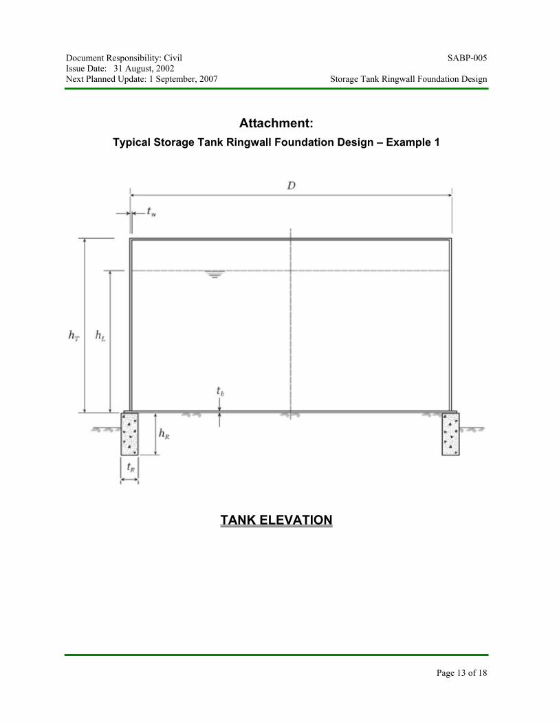
Attachment:Typical Storage Tank Ringwall Foundation Design – Example 1
TANK ELEVATION
Document Responsibility: Civil SABP-005Issue Date: 31 August, 2002Next Planned Update: 1 September, 2007 Storage Tank Ringwall Foundation Design
Page 14 of 18
TANK DATA (from certified vendor drawing)
Floating Roof TankDiameter D = 360 ft (109.728 m)Tank Height hT = 60 ftAvg. Wall Plate Thickness tw = 0.885”Bottom plate Thickness = 0.375”Height of Liquid hL = 59 ftSpecific Weight of Product = 0.859Unit Weight of Product γP = 62.4 x 0.859 = 53.60 lbs/ft³Add 5% to weight of tank shell for stairs and platforms
SOIL DATA (from Geotechnical Soil Investigation Report)
Unit Weight of Soil γS = 125 lb/c.f.Ka = 0.30Allowable Bearing Pressure = 4 ksf
FOUNDATION MATERIAL:
Concrete f’c = 4,000 psiConcrete γC = 150 lbs / c.f.Reinforcement fy = 60,000 psi
Wind Load:
Basic wind speed = 93 mph per SAES-A-112
Seismic Load:
Seismic Zone 0
Stability Analysis:
Since tank diameter D is less than tank height hL, wind analysis is not required. No uplift willoccur due to wind load.
Tank Ringwall Design & Soil Bearing Pressure:
Assume ringwall depth hR = 4.1 ft (1250 mm)Assume ringwall thickness tR = 18.00” (457 mm)
Weight of tank wall per foot of circumferenceWW = 0.885 x 40.8 x 60 x 1.05 = 2275 (lb/ft)
Document Responsibility: Civil SABP-005Issue Date: 31 August, 2002Next Planned Update: 1 September, 2007 Storage Tank Ringwall Foundation Design
Page 15 of 18
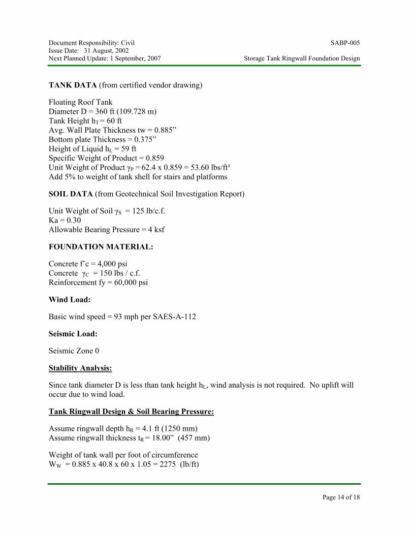
Typical Section Through Tank
Document Responsibility: Civil SABP-005Issue Date: 31 August, 2002Next Planned Update: 1 September, 2007 Storage Tank Ringwall Foundation Design
Page 16 of 18
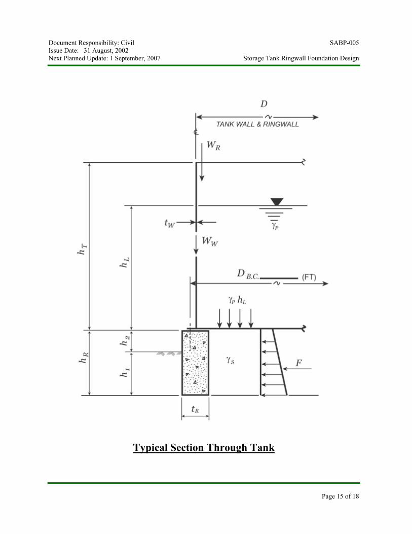
Forces Acting on Ringwall
Soil Bearing Pressure under ringwall:
Po = 12 (WW + WR) / tR + γP hL/2 + hR γC Eq. b
Po = 12 (2275 + 0) / 18.00 + (53.60 x 59) /2 + 4.1 x 150
Po = 1,517 + 1,581 + 615 = 3, 713 psf < 4000 psf O.K.
Soil Bearing Pressure under tank:
Po = γP hL+ γS hR Eq. a
Po = (53.60 x 59) + (125 x 4.1) = 3,675 psf < 4000 psf O.K.
Soil bearing pressure under ringwall and tank bottom is almost equal, therefore, no settlementproblem will occur.
Document Responsibility: Civil SABP-005Issue Date: 31 August, 2002Next Planned Update: 1 September, 2007 Storage Tank Ringwall Foundation Design
Page 17 of 18
Ringwall Thickness:
tR = 24 (WW + WR) / {γP hL- 2 hR (γC - γS )} Eq. 1
tR (product) = 24 (2275 + 0) / {53.60 x 59 – 2x4.1(150 – 125)}
tR (product) = 18.46 inch vs 18.00 inch provided - say O.K.
tR (hydrotest) = 24 (2275 + 0) / {62.4 x 59 – 2x4.1(150 – 125) = 15.70 inch < 18.00 inch O.K.
Ringwall Reinforcement:
Horizontal Reinforcement
Radial outward force F on ringwall (lb/ft)
F = Ka hR (γP hL + γS hR / 2) (lb/ft) Eq. 2
F = 0.30 x 4.1 (53.60 x 59 + 125 x 4.1 / 2) = 4,205 (lb/ft)
For Hydrotest :FH = 0.3 x 4.1 (62.4 x 59 + 125 x 4.1 / 2) = 4,844 (lb/ft)
Hoop tension T in ringwall (lbs) = ½ F D (lbs) - working stress design
T = ½ x 4,205 x 360 / 1000 = 756.9 kips
TH = ½ x 4,844 x 360 / 1000 = 872 kips Controls
Using ultimate stress design
TU = 1.7 T (kips) Eq. 4
TU = 1.7 x 872 = 1,482.4 kips
As (req’d) = TU /Φfy
As (req’d) = 1,482.4 / 0.9 x 60 = 27.45 in²
Document Responsibility: Civil SABP-005Issue Date: 31 August, 2002Next Planned Update: 1 September, 2007 Storage Tank Ringwall Foundation Design
Page 18 of 18
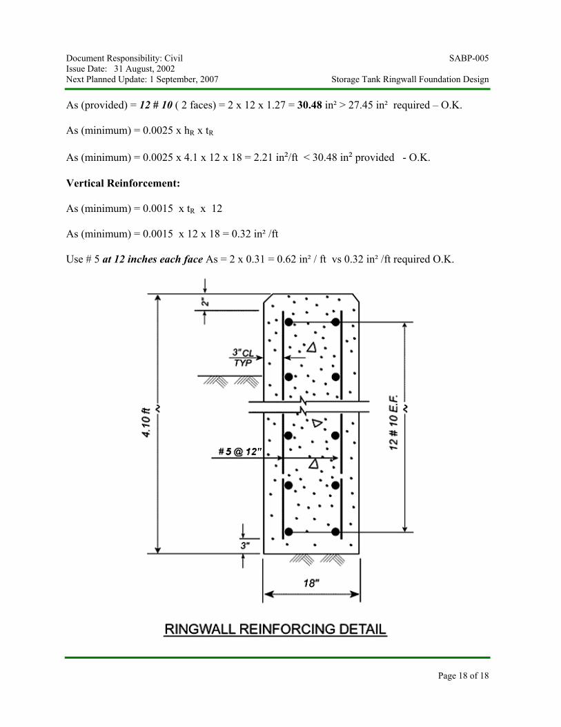
As (provided) = 12 # 10 ( 2 faces) = 2 x 12 x 1.27 = 30.48 in² > 27.45 in² required – O.K.
As (minimum) = 0.0025 x hR x tR
As (minimum) = 0.0025 x 4.1 x 12 x 18 = 2.21 in²/ft < 30.48 in² provided - O.K.
Vertical Reinforcement:
As (minimum) = 0.0015 x tR x 12
As (minimum) = 0.0015 x 12 x 18 = 0.32 in² /ft
Use # 5 at 12 inches each face As = 2 x 0.31 = 0.62 in² / ft vs 0.32 in² /ft required O.K.


