Rigging - LGHRigging Rigging | Overview For specific product information, refer to the group of...
87
Transcript of Rigging - LGHRigging Rigging | Overview For specific product information, refer to the group of...


Rigging
Rigging | Overview
For specific product information, refer to the group of equipment within this section’s overview on the following page for that product’s corresponding page number.
Lifting Gear Hire stocks a complete range of equipment for virtually any lifting or moving application.
Some of the industries we serve:
EnergyUtilitiesConstructionMaintenance
TransportationMarine/Ship BuildingPetrochemicalPharmaceutical
All rental equipment is available throughout North America.
194 (800) 878-7305 www.RentLGH.com [email protected]
Rigging | Overview

Rigging
Rigg
ing
| Ind
ex
195(800) 878-7305 www.RentLGH.com [email protected]
Rigging | Index
Rigging Equipment Manufacturer(s) Pages
How To Measure
Length<
G-4163
Digital Load Links Tractel, Dillon 196 – 200
Chain Slings Pewag 201 – 204
Chain Slings Hardware Pewag 205 – 208
Master Link Crosby 209 – 210
ROV Shank Hook GN Rope Fittings 211
Web Slings Lift-All, DD Sling 212 – 216
Wire Rope Slings Lift-All 217 – 225
Polyester Round Slings Lift-All 227 – 230
Shackles Van Beest, Crosby 231 – 238
Swivels & Hoist Rings Crosby 239 – 243
Clips & Turnbuckles Crosby 244 – 247
Modular Spreader Beams Modulift® 248 – 265
Endcap Spreader Beams Maxibar 266 – 267
Telescopic Spreader Beams Crosby, Tandemloc 268 – 270
Lifting Beams Caldwell, ARS 271 – 274
Pallet Lifter Caldwell 275
Tri-Link GN Rope Fittings 276 – 277
Collector Ring — 278

Rigging
Digital Load Links
196 (800) 878-7305 www.RentLGH.com [email protected]
Model RLP25T
Digital Load Links 2,200Lbs. – 1,100,000 Lbs. | RLP Series
D
G
A
C
E
B F
Model Capacity (Lbs.) Resolution Units Weight Safety
FactorBattery
TypeBattery
LifeDisplay
TypeOperating
Temp Accuracy Frequency System Range Data Rate Protection
RLP1T 2,200 1lb lb 3.1 12:1
Handheld 2 x AA/Load cell
4 x AA
Handheld 60 hours/ Load cell
1200 hours continuous
6 digit 25mm / 1"
LCD
-10°C to +50°C / 14°F
to 122°F
± 0.3% of applied
load2.4 GHz 2,300 ft.
3 Hz – up to 200 Hz can be
ordered for dynamic load
monitoring applications
IP67 / NEMA 6
RLP2T5 5,500 2lb lb 3.1lb 5:1
RLP6T5 13,000 2lb lb 4.4lb 5:1
RLP12T 26,000 5lb lb 7.1lb 5:1
RLP25T 55,000 10lb lb 11lb 5:1
RLP35T 77,000 10lb lb 19lb 5:1
RLP55T 110,000 20lb lb 25.3lb 5:1
RLP75T 165,000 20lb lb 35.3lb 5:1
RLP100T 220,000 100lb lb 75lb 5:1
RLP150T 330,000 100lb lb 101.4lb 4:1
RLP200T 440,000 200lb lb 158.7lb 5:1
RLP250T 550,000 200lb lb 158.7lb 4:1
RLP300T 660,000 200lb lb 260lb 5:1
RLP500T* 1,100,000 200lb lb 546.7lb 5:1
Specifications
Green shading reflects rental inventory.* RLP500T is not DNV certified.
Model A B C D ØE F G Crosby Shackle
Loading Pin Ø
RLP1T 8.03” 1.69” 3.98” 5.75” 0.96” 1.89” 0.75” G2130 3/4”
RLP2T5 8.03” 1.69” 3.98” 5.75” 0.96” 1.89” 0.75” G2130 3/4”
RLP6T5 9.80” 1.69” 3.98” 6.50” 1.50” 2.60” 1.26” G2130 1”
RLP12T 12.01” 1.85” 3.98” 7.60” 1.87”
Not relevant in this capacity.
G2130 1 3/8”
RLP25T 13.39” 2.36” 4.53” 8.46” 2.17” G2130 2”
RLP35T 15.47 2.95” 4.96” 8.86” 2.36” G2130 2 1/4”
RLP55T 16.69” 2.95” 6.42” 9.06” 2.99” G2140 2 1/4”
RLP75T 18.50” 2.95” 7.95” 10.24” 2.99” G2140 2 3/4”
RLP100T 23.94” 3.90” 10.04” 12.60” 4.29” G2140 3 1/4”
RLP150T 26.38” 3.90” 11.93” 14.17” 4.29” G2140 3 3/4”
RLP200T 27.56” 5.67” 12.60” 13.78” 5.20” G2140 4 3/4”
RLP250T 27.56” 5.67” 12.60” 13.78” 5.20” G2140 5”
RLP300T 31.73” 5.91” 16.77” 13.78” 6.30” G2140 6”
RLP500T* 36.61” 5.91” 22.44” 17.71” 7.87” G2140 7 1/4”
Dimensions
Green shading reflects rental inventory.* RLP500T is not DNV certified.
• Proprietary 2.4 GHz wireless• Industry leading wireless range of 700m/2300ft• Error free data transmission• Unrivalled resolution• Environmentally sealed to IP67/NEMA6• 90db Audible overload alarm• Unmatched battery life of 1200hrs• Internal antennae
• Compact size• Remote on-off• Lightweight aluminum• 100 Hz Peak hold• Advanced options available• Push button tare• Design validated by F.E.A.• Units are DNV GL approved
Items onthis page are
availablefor rent.
AVA
ILABLE
FOR RENT

Rigging
Digi
tal L
oad
Link
s
197(800) 878-7305 www.RentLGH.com [email protected]
Model Number Capacity x Resolution Normal / Enhanced Body Construction and Overload Design
EDx-2.5K 2,500 lbf x 2/0.5 10,000 N x 10/2
Aircraft quality 2024 Aluminum 700% Ultimate overload protectionEDx-5K 5,000 lbf x 5/1 20,000 N x 20/5
EDx-10K 10,000 lbf x 10/2 50,000 N x 50/10
EDx-25K 25,000 lbf x 20/5 100,000 N x 100/20
Aircraft quality E4340 Alloy Steel 500% Ultimate overload protectionEDx-55K 55,000 lbf x 50/10 250,000 N x 200/50
EDx-100K 100,000 lbf x 100/20 500,000 N x 500/100
EDx-160K 160,000 lbf x 200/50 ---
Aircraft quality E4340 Alloy Steel 400% Ultimate overload protection
EDx-220K 220,000 lbf x 200/50 ---
EDx-330K 330,000 lbf x 500/200 ---
EDx-550K 550,000 lbf x 500/200 ---
Specifications
Green shading reflects rental inventory.
Digital Load Links 2,500 – 550,000 Lbs. | EDXtreme
Model EDx-100K
Model Number A in. B in. C in. D in. E in. F in. G in. H in. J in.
EDx-2.5K 10.6 5.0 7.8 1.06 0.75 15.3 13.4 1.36 1.69
EDx-5K 10.6 5.0 7.8 1.06 0.75 15.3 13.4 1.36 1.69
EDx-10K 11.4 5.3 8.1 1.46 1.00 17.5 15.7 2.17 2.28
EDx-25K 11.5 5.3 7.9 2.01 1.38 21.0 18.5 3.50 3.25
EDx-55K 13.7 6.0 9.0 2.91 1.97 28.7 25.2 5.70 4.96
EDx-100K 15.8 6.8 10.3 4.13 2.75 38.8 33.7 8.98 7.09
EDx-160K 16.5 7.8 10.3 4.13 2.75 39.3 33.7 8.58 7.09
EDx-220K 18.0 7.8 11.0 5.00 3.25 46.9 40.4 11.14 7.48
EDx-330K 21.0 8.8 12.6 5.25 3.75 53.9 45.6 12.3 9.0
EDx-550K 27.0 9.8 17.5 8.5 5.00 75.8 62.8 17.9 13.0
Dimensions
Green shading reflects rental inventory.
Items onthis page are
availablefor rent.
AVA
ILABLE
FOR RENT

Rigging
Digital Load Links
198 (800) 878-7305 www.RentLGH.com [email protected]
Model Unit Weight (lbs.)
Weight with Shackles (lbs.)
Approx. Shipping Weight (lbs.)
EDx-2.5K 4.3 8.6 13
EDx-5K 4.4 8.7 13
EDx-10K 5.6 14 22
EDx-25K 16 40 46
EDx-55K 25 96 125
EDx-100K 38 238 296
EDx-160K 54 250 325
EDx-220K 70 410 480
EDx-330K 120 650 750
EDx-550K 250 1,490 1,600
Communicator 1 n/a 10
Weights
Green shading reflects rental inventory.
Dynamometer SpecificationsEnclosure: Designed to NEMA4X/IP55. Suitable for continuous outdoor use.Accuracy: 0.1% of capacity up to EDx-100K.* 0.3% of capacity for EDx-160K and above.*Repeatability: 0.1% of capacity up to EDx-100K.* 0.3% of capacity for EDx-160K and above.** Normal resolution mode with Dillon provided shackles
Safe overload: 200% of capacityBody protection: Aluminum and alloy steel capacities are powder painted.Bearings: Unmatched repeatability attained by needle bearings in shackle pin holes up to EDx-10K. Shackle pin acts as inner race.Shackles: Forged industry standard anchor shackles. Models up to EDx-10K use precision machined shackle pin. Higher capacities use bar stock pin.Display: 128 x 64 dot-graphic LCD display shows up to 6 digits 1.0” (26 mm) high plus annunciators and softkeys. Digits are .11 inches (7mm) thick for unmatched readability.Display update rate: 2 times per second.Connector: Recessed sealed connector may be used for serial communications or connection to a Communicator remote.RS-232: Print or extract data easily. Continuous output can drive a scoreboard. Configurable poll character.Calibration: Traceable to the National Institute of Standards and Technology. Certificate included with curve of readings. Passes only with three consecutive confirming runs, with all points in specification.Battery Life: 400 hours continuous use with two C-cell alkaline batteries. 150 hours with Radio Link system.Operating temperature: -4° F to 158° F (-20° to 70° C)Included with Instrument: All include certificate of calibration, manual and batteries. Plastic carry case included for EDx-2.5 to EDx-100K. Higher capacities include rugged plywood storage crate. Instruments with shackles include centering spacers (EDx-50K & up) and storage crate (EDx-50k to EDx-160K).Options: Shackles. 2.4 GHz radio board. Display backlight.Approval: CE, one all capacities excluding 550K.
Communicator SpecificationsEnclosure: Designed to NEMA 3 / IP44 with optional sleeve. Suitable for protected outdoor use.Instrument size: 9.0 x 4.6 x 1.8 inch (228 x 117 x 45mm).Accuracy: Not applicable. Only sends and receives digital information.Display: 128 x 64 dot-graphic LCD display can show full readings up to 5 instruments.Battery life: 80 hours continuous radio using four AA alkaline batteries under typical use.Operating temperature: -4° F to 158° F (-20° to 70° C)Connectors: Sealed connectors may be used for serial communications and wired connection to an EDXtreme dynamometer.RS-232 communication: Print or extract data easily. Continuous output can drive a scoreboard. Configurable poll character.Included with remote: Carry case and batteries.Accessories: Rubberized case protector sleeve. Remote wall mount bracket. Serial and remote cable assemblies. External power supply.Approval: CE
Radio SpecificationsFCC Certified: For unlicensed low power devices. No radio licensing or permits required for normal operation.* (In the US and Canada. Check local ordinances in other countries.)Frequency: 2.4 GHz spread-spectrum operates between 2.402-2.4835 GHz. Output level: 10 mW (20dBm)Display update rate: 1 times per second.Number of networks: 63 remotes can operate independently in the same airspace with unique channels.Number of links remote can control: Up to 15 addresses are available per network channel.Configuration: Address and Network channels are front-panel configurable.Antenna: Integral antenna.Range: Open-air – Up to 600 feet, line-of-sight. Indoors-dependent upon environment with 300 feet common.
Digital Load Links 2,500 – 550,000 Lbs. | EDXtreme Items on
this page areavailablefor rent.
AVA
ILABLE
FOR RENT

Rigging
Digi
tal L
oad
Link
s
199(800) 878-7305 www.RentLGH.com [email protected]
Model A B D E F G H
WNI50TCU 4.02 5.00 2.32 0.51 M20 x 2.5 5.98 6.22
WNI150TCU 5.98 7.24 3.15 1.02 M20 x 2.5 17.01 8.19
Dimensions
Green shading reflects rental inventory.
Digital Load Links 110,000 – 330,000 Lbs. | WN Series | Wireless Compression Load Cell
Note: Requires the use of a wireless handheld display or wireless software package
Model Capacity Resolution Units Weight Safety Factor
Battery Type
Battery Life
Operating Temp Accuary Frequency System
Range Data Rate Protection
WNI50TCU 110,000 20 lb 13.643:1 Load cell 4 x
AA Alkaline
Load cell 1200 hrs
continuous14 F to 122 F ± 0.3% of
applied load 2.4Ghz 2300 feet3 Hz
(Configurable to 200 Hz)
IP67 / NEMA 6WNI150TCU 330,000 100 lb 34
Straightpoint WNI50TCU
Green shading reflects rental inventory.
A
H
E
G
F
D
B
Items onthis page are
availablefor rent.
AVA
ILABLE
FOR RENT

Rigging
Digital Load Links
200 (800) 878-7305 www.RentLGH.com [email protected]
SW-MWLC100For more complex applications our SW-MWLC100 software package can be configured to
simultaneously display up to 100 load cell channels of live data.
Graphical pages can be built showing the data in a variety of formats including digital display or bars.
Up to eight pages can be defined and the pages easily navigated between. A variety of image formats
can be imported, including JPG, GIF, PDF and DXF.
Custom applications including branding and color scheme are available. Please contact our
sales department for pricing.
Both SW-MWLC software packages are supplied with a SW-USBBSE extended range
USB dongle.
Features and benefits:• Displays and logs data from up to 24 or 100 Straightpoint wireless load cells
• Mapping / graphical capabilities
• Webserver offers remote viewing on iPads / tablets / smart phones and aslo supplies
JSON data on demand
• Logging at timed intervals, manual or on overload / underload
• Visual and audible alarms indicates overload, low battery & comms error
• Zoom in to channel to see data trends and history
• Export and log data in CSV format
Model IP Rating (SW-USBBSE)
Operating Temperature License Frequency Range Loadcell
InputsPC
Requirements Operating System
SW-MWLC100 IP65 or NEMA 4X -10C to +50C or 14F to 122F License Free 2.4GHz 250 meters
or 800 feet Up to 100 Intel i3 processor with 2GB RAM
Windows XP, Vista, Windows 7 or Windows 8
Straightpoint WNI50TCU
Green shading reflects rental inventory.
Digital Load Links Wireless Compression Load Cell Software & Accessories Items on
this page areavailablefor rent.
AVA
ILABLE
FOR RENT

Rigging
Chai
n Sl
ings
201(800) 878-7305 www.RentLGH.com [email protected]
Grade 120 Alloy (in.)
Nominal Thickness
dPitch
t
WidthWLL lb Safety
Factor 4:1Breaking load lb.
Weight lb./ft.inside b1
min.Outside b2
max.
NI 720 (9/32) .276 (7 mm) 0.866 0.393 1.024 5,200 20,800 0.738
NI 1020 (3/8) .394 (10 mm) 1.3 0.559 1.457 10,600 42,400 1.475
NI 1320 (1/2) .512 (13mm) 1.614 0.732 1.949 17,900 71,600 2.548
Dimensions
Green shading reflects rental inventory.
Chain Slings Dimensions & Load Ratings
Model Number
Diameter (in.)
Grade 100 Alloy
Grade 80 Alloy
Grade 50 Stainless
Steel
Nominal Diameter
DPitch
P
WidthWeight lb./ft.inside W1
min.Outside W2
max.
Pew 197 3/16 — — Nik 5 0.197 0.63 0.295 0.728 0.376
Pew 217 7/32 Ni 5.50 Ni 5.5 — 0.217 0.68 0.319 0.787 0.47
Pew 276 9/32 Ni 70 Ni 7 Nik 7 0.276 0.826 0.375 0.992 0.738
Pew 315 5/16 Ni 80 Ni 8 — 0.315 0.945 0.43 1.134 0.939
Pew 394 3/8 Ni 100 Ni 10 Nik 10 0.394 1.181 0.531 1.417 1.475
Pew 512 1/2 Ni 130 Ni 13 Nik 13 0.512 1.535 0.689 1.843 2.548
Pew 63 5/8 Ni 160 Ni 16 Nik 16 0.63 1.89 0.846 2.268 3.83
Pew 787 3/4 Ni 200 Ni 20 — 0.787 2.44 1.008 2.776 5.78
Pew 866 7/8 Ni 220 Ni 22 — 0.866 2.598 1.161 3.118 7.324
Pew 1024 1 Ni 260 Ni 26 — 1.024 3.071 1.378 3.685 10.214
Pew 1260 1 1/4 — Ni 32 — 1.26 3.78 1.701 4.528 15.455
Weights
Green shading reflects rental inventory.
Model
Grade 120 Alloy Grade 100 Alloy Grade 80 Alloy Grade 50 Stainless Steel
Diameter (in.)
Working load lbs.
Safety factor
4:1
Manufac. test load
lbs.Breaking load lbs
Diameter (in.)
Working load lbs.
Safety factor
4:1
Manufac. test load
lbsBreaking load lbs.
Diameter (in.)
Working load lbs.
Safety factor
4:1
Manufac. test load
lbs.Breaking load lbs.
Diameter (in.)
Working load lbs.
Safety factor
4:1
Manufac. test load
lbs.Breaking load lbs.
Pew 0 — — — — — — — — — — — — 3/16 1,100 2,200 4,400
Pew 7/32 9/32 5,200 10,400 20,800 7/32 2,700 5,400 10,800 7/32 2,100 4,200 8,400 — — — —
Pew 9/32 — — — — 9/32 4,300 8,600 17,200 9/32 3,500 7,000 14,000 9/32 2,200 4,400 8,800
Pew 5/16 3/8 10,600 21,200 42,400 5/16 5,700 11,400 22,800 5/16 4,500 9,000 18,000 — — — —
Pew 3/8 1/2 17,900 35,800 71,600 3/8 8,800 17,600 35,200 3/8 7,100 14,200 28,400 3/8 4,400 8,800 17,600
Pew 1/2 — — — — 1/2 15,000 30,000 6,000 1/2 12,000 24,000 48,000 1/2 7,100 14,200 28,200
Pew 5/8 — — — — 5/8 22,600 45,200 90,400 5/8 18,100 36,200 72,400 5/8 11,000 220,00 44,000
Pew 3/4 — — — — 3/4 35,300 70,600 141,200 3/4 28,300 56,600 113,200 — — — —
Pew 7/8 — — — — 7/8 42,700 85,400 170,800 7/8 34,200 68,400 136,800 — — — —
Pew 1 — — — — 1 59,700 119,400 238,800 1 47,700 95,400 190,800 — — — —
Pew 1 1/4 — — — — 1 1/4 90,400 180,800 361,600 1 1/4 72,300 144,600 289,200 — — — —
Load Rating
Green shading reflects rental inventory.
This page containsThis page contains
ITEMS ONLYITEMS ONLYSALESALE

Rigging
Chain Slings
202 (800) 878-7305 www.RentLGH.com [email protected]
Pewag lifting chain and fittings are marked with a batch identification number and the manufacturer’s identification marking: the number, “120” or “12” to indicate Grade 120 Alloy, “100”, “10” or “V” to indicate Grade 100 Alloy, “8” to indicate Grade 80 Alloy and “50” to indicate Grade 50 Stainless.
All Alloy chains are 100% tested to 2 times the working load values and are furnished with a test certification to this effect.
Every chain sling manufactured by Pewag is supplied with a steel tag and test certificate as shown.
Chain Slings ID & Reduction Factors
This page containsThis page contains
ITEMS ONLYITEMS ONLYSALESALE
Grade 50Grade 120 Grade 100 Grade 80
Single-leg chain Multi-leg chain
To be used for various slinging methods and conditions without shock loads. Grade 120 12” point I.D. tag

Rigging
Chai
n Sl
ings
203(800) 878-7305 www.RentLGH.com [email protected]
Chain Slings Maximum Capacity Ratings
Safety Factor 1-leg slings 2-leg-slings 3-leg slings and 4-leg slings
4:1
Angle 90 degrees 60 degrees 45 degrees 30 degrees 60 degrees 45 degrees 30 degrees
Load Factor 1 1.7 1.4 1 2.6 2.1 1.5
Specifications
Ni 5.50 7/32” 2,700 4,700 3,800 2,700 7,000 5,700 4,000
Retains 100% of work load limit at minus 40-400 degrees F. Not for
temperatures over 400 degrees F.
Special G100 750 F chain for elevated temperature available.
Ni 70 9/32” 4,300 7,400 6,100 4,300 11,200 9,100 6,400
Ni 80 5/16” 5,700 9,900 8,100 5,700 14,800 12,100 8,500
Ni 100 3/8” 8,800 15,200 12,400 8,800 22,900 18,700 13,200
Ni 130 1/2” 15,000 26,000 21,200 15,000 39,000 31,800 22,500
Ni 160 5/8” 22,600 39,100 32,000 22,600 58,700 47,900 33,900
Ni 200 3/4” 35,300 61,100 49,900 35,300 91,700 74,900 53,000
Ni 220 7/8” 42,700 74,000 60,400 42,700 110,900 90,600 64,000
Ni 260 1” 59,700 103,400 84,400 59,700 155,100 126,600 89,550
Grade 100 Alloy
Ni 5.5 7/32” 2,100 3,600 3,000 2,100 5,500 4,400 3,200
Retains 100% of work load limit at minus 40-400 degrees F, 90% at
400-570 degrees F, and 75% at 570-750 degrees F.
Not for temperatures over 750 degrees F.
Ni 7 9/32” 3,500 6,100 4,900 3,500 9,100 7,400 5,200
Ni 8 5/16” 4,500 7,800 6,400 4,500 11,700 9,500 6,800
Ni 10 3/8” 7,100 12,300 10,000 7,100 18,400 15,100 10,600
Ni 13 1/2” 12,000 20,800 17,000 12,000 31,200 25,500 18,000
Ni 16 5/8” 18,100 31,300 25,600 18,100 47,000 38,400 27,100
Ni 20 3/4” 28,300 49,000 40,000 28,300 73,500 60,000 42,400
Ni 22 7/8” 34,200 59,200 48,400 34,200 88,900 72,500 51,300
Ni 26 1” 47,700 82,600 67,400 47,700 123,900 101,200 71,500
Ni 32 1 1/4” 72,300 125,200 102,200 72,300 187,800 153,400 108,400
Grade 80 Alloy
Nik 5 3/16” 1,100 1,900 1,600 1,100 2,900 2,300 1,700 Retains 100% of work load limit at minus 50-750 degrees F,
75% at 750-1,100 degrees F, and 50% at 1,100-1,290 degrees F.
Not for temperatures over 1,290 degrees F.
Nik 7 9/32” 2,200 3,800 3,100 2,200 5,700 4,600 3,300
Nik 10 3/8” 4,400 7,500 6,200 4,400 11,500 9,300 6,600
Nik 13 1/2” 7,100 12,100 10,000 7,100 18,500 14,900 10,700
*Nik 16 5/8” 11,000 18,700 15,600 11,000 23,100 23,100 16,500
Grade 50 Stainless Steel
*Sling work load limits are reduced 10% when the HSK16 eye sling hook is used.Green shading reflects rental inventory.
Ni 720 9/32” 5,200 9,000 7,400 5,200 13,500 11,000 7,800 Retains 100% of work load limit at minus 40-400 degrees F. Not for temperatures
over 400 degrees F.Ni 1020 3/8” 10,600 18,400 15,000 10,600 27,500 22,500 15,900
Ni 1320 1/2” 17,900 31,000 25,300 17,900 46,500 38,000 26,900
Grade 120 Alloy Temperature Resistance
This page containsThis page contains
ITEMS ONLYITEMS ONLYSALESALE

Rigging
Chain Slings
204 (800) 878-7305 www.RentLGH.com [email protected]
Standard Assemblies of Pewag ChainChain slings can be delivered with Connex connecting links and accessories ready fitted, with clevis fittings, or in welded construction. Should you require any chain sling assemblies other than those in this brochure, please send us a sketch of the desired model. The standard tolerance for the length “L” is + 2 – 0 pitch.
Ordering Data – Example of how to order:1. Determine the maximum load to be lifted.2. Determine the type of slings needed (single, double, etc.)3. Estimate the proper angle between the leg of the sling and the load during operation4. Select the proper fittings (hooks, master links, etc.)5. Determine the overall reach (measured from bearing point on master link to bearing point of fitting).6. Choose chain size which meets your required work load, angle and reduction factor 7. Choose grade, type and finish of steel which meets your requirements.
Chain Slings Standard Chain Sling Assemblies
This page containsThis page contains
ITEMS ONLYITEMS ONLYSALESALE
Rigging
Chai
n Sl
ing
Hard
war
e
205(800) 878-7305 www.RentLGH.com [email protected]
Chain Sling Hardware Grade 100 Alloy Components
Master Link A
Master link for single leg slings and 2-leg slings. Proof tested 2x wll (working load limit) of master link only.
Enlarged Master Link M
The same as master link A above; however because of their larger inner dimensions, suitable for larger crane hooks or special hooks. Proof tested 2x wll (working load limit) of master link.
Master Link Assemblies V
For assembling 3- and 4-leg chains with connex links, and for rope slings. Proof tested.
VXK 1
For 1-leg chains with shortening hook.
VXK 4
For 3- and 4-leg slings with shortening hooks.
VXK 2
For 2-leg slings with shortening hooks.
Model WLL* Lbs. 4:1
Stock Dia. (in.) d t w Weight
Lb./Pc.Master Link for Chain 0
1-leg 2-legA 100 3,800 3/8 0.39 3.15 1.97 0.31 7/32
A 130 5,800 1/2 0.51 4.33 2.36 0.75 9/32 7/32
A 160 7,500 5/8 0.63 4.33 2.36 1.17 5/16 9/32
A 180 10,000 3/4 0.71 5.31 2.95 1.9 3/8 5/16
A 220 16,700 7/8 0.91 6.3 3.54 3.53 1/2 3/8
A 260 26,000 1 1.06 7.09 3.94 5.42 5/8 1/2
A 320 39,100 1 1/4 1.3 7.87 4.33 9.13 3/4 5/8
A 360 61,100 1 1/2 1.42 10.24 5.51 13.71 7/8 3/4
A 450 83,100 1 3/4 1.77 13.39 7.09 28.26 1 7/8
A 500 111,000 2 1.97 13.78 7.48 36.49 1 1/4 1
A 560 147,300 2 1/4 2.361 15.75 7.87 59.55 1 1/4
Master Link A Specifications
Green shading reflects rental inventory.
Model WLL* Lbs. 4:1
Stock Dia. (in.) d t w Weight
Lb./Pc.Master Link for Chain 0
1-leg 2-legM 100 3,800 3/8 0 4 3 0 7/32
M 130 6,100 1/2 1 5 3 1 9/32 7/32
M 160 8,400 5/8 1 6 3 1 5/16 9/32
M 180 12,800 3/4 1 6 4 2 3/8 5/16
M 220 18,500 7/8 1 6 4 4 1/2 3/8
M 260 30,000 1 1 7 4 6 5/8 1/2
M 320 45,000 1 1/4 1 9 5 11 3/4 5/8
M 360 61,100 1 1/2 2 11 6 16 7/8 3/4
Enlarged Master Link M Specifications
Green shading reflects rental inventory.
Model Stock Dia. (in) e t w Weight
Lb./Pc.Assembly
for Chain 0 3-and 4-leg
V 5.50 3/4 7.44 5 3 3 7/32
V 70-80 7/8 9.06 6 4 5 9/32 + 5/16
V 100 1 10.43 7 4 8 3/8
V 130 1 1/4 12.4 8 4 14 1/2
V 160 1 1/2 15.75 10 6 22 5/8
V 200 2 19.69 14 7 50 3/4
V 220 2 20.47 14 7 55 7/8
V 260 2 3/8 22.44 16 8 83 1
V 32 2 3/4 25.98 18 10 147 1 1/4
Master Link Assemblies V Specifications
Green shading reflects rental inventory.
Model For Chain 0 d t w e Weight Lb./Pc.
VXK 1-70 9/32 0.51 4.33 2.36 9.13 2.12
VXK 1-100 3/8 0.71 5.31 2.95 11.57 4.65
VXK 1-130 1/2 0.91 6.3 3.54 14.29 9.48
VXK 1-160 5/8 1.06 7.09 3.94 16.26 16.01
VXK 2-70 9/32 0.63 4.33 2.36 9.13 3.9
VXK 2-100 3/8 0.91 6.3 3.54 12.56 9.04
VXK 2-130 1/2 1.06 7.09 3.94 15.08 17.33
VXK 2-160 5/8 1.3 7.87 4.33 17.05 30.29
VXK 4-70 9/32 0.91 6.3 3.54 13.86 10.67
VXK 4-100 3/8 1.06 7.09 3.94 16.69 19.44
VXK 4-130 1/2 1.3 7.87 4.33 20.39 38.05
VXK 4-160 5/8 1.42 10.24 5.51 24.92 64.51
Clevis Master Sets VXK 1 Specifications
Green shading reflects rental inventory.
Items onthis page are
availablefor rent.
AVA
ILABLE
FOR RENT

Rigging
Chain Sling Hardware
206 (800) 878-7305 www.RentLGH.com [email protected]
Model Stock Dia. (in.) e t w Weight
Lb./Pc.Assembly
for chain 0 3- and 4-leg
VM5.50 3/4 8.43 6.3 3.74 3.15 7/32VM70-80 7/8 9.06 6.3 4.33 5.31 9/32 + 5/16
VM100 1 10.83 7.48 4.33 8.84 3/8VM130 1 1/4 13.58 9.06 5.12 15.21 1/2VM160 1 1/2 16.34 10.83 5.91 24.52 5/8VM200 2” 19.69 13.78 7.48 50.42 3/4
Enlarged Master Link Assemblies VM SpecificationsEnlarged Master Link Assemblies VM
For 3- and 4-leg chain slings. Large inner width. Proof tested.
Connex Connecting Link C
General connecting link for connection of: Master links to chain, chain to chain, hooks to chain.
Connex Connecting Link CL
Non-removable.
Clevis Shortening Hook XK
In line shortening hook not for basket configurations.
Clevis Sling Hook KHS
General purpose hook with forged safety catch.
Clevis Grab Hook KP
First G100 grab hook that does not require WLL reduction when used for shortening
Chain Sling Hardware Grade 100 Alloy Components
Model WLL Lbs. 4:1 For Chain (in.) e c s d b g Weight Lb./Pc.
C5.50 2,700 7/32 1.75 0.31 0.43 0.3 1.54 0.56 0.13C70 4,300 9/32 2.01 0.39 0.51 0.35 1.83 0.64 0.26C80 5,700 5/16 2.42 0.45 0.59 0.39 2.09 0.72 0.4
C100 8,800 3/8 2.83 0.5 0.7 0.5 2.48 0.91 0.73C130 15,000 1/2 3.46 0.75 0.87 0.66 3.11 1.09 1.54C160 22,600 5/8 4.06 0.83 1.14 0.83 4.17 1.3 2.51C200 35,300 3/4 4.53 1.16 1.37 0.96 4.65 1.64 4.72C220 42,700 7/8 5.31 1.14 1.5 1.06 5.77 1.89 7.08C260 59,700 1 7.48 1.57 1.81 1.18 6.88 2.36 15.77
Connex Connecting Link C Specifications
Model WLL Lbs. 4:1 For Chain (in.) e c s d b g Weight Lb./Pc.
CL 70 4,300 9/32 2.01 0.39 0.51 0.35 1.83 0.64 .26CL 100 8,800 3/8 2.83 0.5 0.7 0.5 2.48 0.91 .73CL 130 15,000 1/2 3.46 0.75 0.87 0.66 3.11 1.09 1.54CL 160 22,600 5/8 4.06 0.83 1.14 0.83 4.17 1.3 2.51
Connex Connecting Link CL Specifications
Model WLL Lbs. 4:1 For Chain (in.) e h a d g1 b Weight Lb./Pc.
KHS 5.50 2,700 7/32 2.72 0.79 0.59 0.29 0.75 2.6 0.44KHS 70 4,300 9/32 3.74 1.1 0.75 0.35 1.06 3.54 1.16KHS 80 5,700 5/16 3.72 1.1 0.75 0.39 1.06 3.54 1.16
KHS 100 8,800 3/8 4.29 1.3 0.98 0.49 1.18 4.25 2.43KHS 130 15,000 1/2 5.35 1.57 1.34 0.63 1.5 5.16 4.41KHS 160 22,600 5/8 6.1 1.93 1.46 0.79 1.81 6.02 7.67KHS 200 35,300 3/4 7.22 2.09 1.81 0.94 2.09 6.97 11.02KHS 220 42,700 7/8 8.41 2.44 1.97 1.06 2.68 7.72 26.68
Clevis Shortening Hook XK Specifications
Model WLL Lbs. 4:1 For Chain (in.) e h a d g1 b Weight Lb./Pc.KHS 5.50 2,700 7/32 2.72 0.79 0.59 0.29 0.75 2.6 0.44KHS 70 4,300 9/32 3.74 1.1 0.75 0.35 1.06 3.54 1.16KHS 80 5,700 5/16 3.72 1.1 0.75 0.39 1.06 3.54 1.16
KHS 100 8,800 3/8 4.29 1.3 0.98 0.49 1.18 4.25 2.43KHS 130 15,000 1/2 5.35 1.57 1.34 0.63 1.5 5.16 4.41KHS 160 22,600 5/8 6.1 1.93 1.46 0.79 1.81 6.02 7.67KHS 200 35,300 3/4 7.22 2.09 1.81 0.94 2.09 6.97 11.02KHS 220 42,700 7/8 8.41 2.44 1.97 1.06 2.68 7.72 26.68
Clevis Sling Hook KHS Specifications
Model WLL Lbs. 4:1 For Chain (in.) e b d g Weight Lb./Pc.
KP 5.50 2,700 7/32 1.77 1.87 0.29 0.31 0.33KP 70 4,300 9/32 2.4 2.28 0.35 0.41 0.84KP 80 5,700 5/16 2.38 2.28 0.39 0.41 0.84
KP 100 8,800 3/8 2.99 2.99 0.49 0.51 1.87KP 130 15,000 1/2 4.09 3.98 0.63 0.67 4.19KP 160 22,600 5/8 4.29 4.65 0.79 0.75 6.17KP 200 35,300 3/4 5.51 5.8 0.94 0.91 7.72KP 220 42,700 7/8 6.59 6.54 1.06 1.02 12.13
Clevis Grab Hook KP Specifications
Green shading reflects rental inventory.
This page containsThis page contains
ITEMS ONLYITEMS ONLYSALESALE

Rigging
Chai
n Sl
ing
Hard
war
e
207(800) 878-7305 www.RentLGH.com [email protected]
Model WLL lbs. 4:1 for chain (in.) e h a b d g weight
lb./pc.KLH 70 4,300 9/32 4.84 1.02 0.79 3.46 0.35 1.34 1.98KLH 80 5,700 5/16 4.84 1.02 0.79 3.46 0.39 1.34 1.98
KLH 100 8,800 3/8 5.67 1.18 0.98 4.21 0.51 1.77 3.53KLH 130 15,000 1/2 7.09 1.57 1.34 5.43 0.63 2.05 6.39KLH 160 22,600 5/8 8.54 1.97 1.38 6.61 0.83 2.36 12.79
Clevis Safety Hook KLH Specifications
Chain Sling Hardware Grade 100 Alloy Components
Clevis Safety Hook KLH
Automatically closes and locks under load.
Clevis Foundry Hook KF
Used when throat opening of sling hook is too small.
Eye Sling Hook HS
For general lifting applications. All hooks with forged safety catch.
Eye Grab Hook P
First G100 grab hook that does not require WLL reduction when used for shortening.
Eye Grab Hook P
Same as above hook with added “safety catch” feature.
Model WLL lbs. 4:1 for chain (in.) e h a g d b weight
lb./pc.KF 70 4,300 9/32 4.74 1.02 0.98 2.52 0.35 4.65 2.2KF 80 5,700 5/16 4.72 1.02 0.98 2.52 0.39 4.65 2.2
KF 100 8,800 3/8 5.51 1.18 1.26 2.99 0.49 5.63 3.92KF 130 15,000 1/2 6.67 1.57 1.57 3.5 0.63 6.69 6.53
Clevis Foundry Hook KF Specifications
Model WLL lbs. 4:1
for chain (in.) e h a d1 d2 g1 b weight
lb./pc.HS 5.50 2,700 7/32 3.33 0.83 0.65 0.79 0.39 0.75 2.68 0.44
HS 70-80 5,700 9/32 + 5/16 4.17 1.06 0.75 0.98 0.43 1.02 3.46 1.1HS 100 8,800 3/8 5.16 1.3 1.02 1.34 0.63 1.22 4.27 2.43HS 130 15,000 1/2 6.46 1.71 1.3 1.69 0.75 1.54 5.26 4.41HS 160 22,600 5/8 7.19 1.97 1.57 1.97 0.96 0.77 6.09 7.72HS 200 35,300 3/4 8.07 2.17 1.89 2.17 1.06 2.09 6.99 10.36HS 220 42,700 7/8 8.86 2.44 1.97 2.36 1.14 2.44 7.72 16.09HS 260 59,700 1 10.19 2.95 2.36 2.75 1.46 2.87 9.25 26.44HS 32 72,300 1 1/4 11.77 3.5 3.07 2.6 1.53 2.87 10.5 49.39
Eye Sling Hook HS Specifications
Model WLL lbs. 4:1 for chain (in.) e b d1 d2 g weight
lb./pc.P 5.50 2,700 7/32 2.01 1.87 0.47 0.33 0.31 0.33
P 70-80 5,700 9/32 + 5/16 2.78 2.28 0.79 0.45 0.41 0.66P 100 8,800 3/8 3.46 2.98 0.87 0.59 0.51 1.43P 130 15,000 1/2 4.45 3.98 1.02 0.71 0.67 3P 160 22,600 5/8 4.76 4.65 1.26 0.83 0.75 4.41P 200 35,300 3/4 5.54 5.51 1.42 1.02 0.91 6.61P 220 42,700 7/8 6.81 6.54 1.65 1.14 1.02 11.02P 260 59,700 1 7.91 7.67 1.96 1.44 1.25 30.4P 32 72,300 1 1/4 9.44 8.12 2.36 1.57 1.53 41
Eye Grab Hook P Specifications
Model WLL lbs. 4:1 for chain (in.) e b d1 d2 g weight
lb./pc.PS 70-80 5,700 9/32 + 5/16 2.78 2.28 0.79 0.45 0.41 0.88
PS 100 8,800 3/8 3.46 2.99 0.87 0.59 0.51 1.98PS 130 15,000 1/2 4.45 3.98 1.02 0.71 0.67 3.97PS 160 22,600 5/8 5.08 4.65 1.26 0.91 0.75 7.94
Eye Grab Hook with Safety Catch PS Specifications
Green shading reflects rental inventory.
This page containsThis page contains
ITEMS ONLYITEMS ONLYSALESALE

Rigging
Chain Sling Hardware
208 (800) 878-7305 www.RentLGH.com [email protected]
Model WLL lbs. 4:1
For chain (in.) e h a b d1 d2 g weight
lb./pc.LH 70-80 5,700 9/32 + 5/16 5.35 1.02 0.79 3.46 1.06 0.47 1.34 1.98
LH 100 8,800 3/8 6.65 1.18 0.98 4.21 1.36 0.59 1.77 3.31
LH 130 15,000 1/2 8.07 1.57 1.34 5.43 1.57 0.79 2.05 5.95
LH 160 22,600 5/8 9.88 1.97 1.38 6.61 1.97 1.06 2.36 12.57
LH 200 35,300 3/4 11.42 2.44 1.97 7.64 2.36 1.18 2.76 17.42
LH 220 42,700 7/8 12.68 2.56 2.05 8.31 2.76 1.26 3.19 24.69
Safety Hook LH SpecificationsSafety Hook LH
Automatically closes and locks under load.
Foundry Hook F
Used when throat opening of sling hook is too small.
Clevis Reevable Master Link KO
Master link used for choker / reeving slings.
Webbing Sling Connecting Link Car
Connecting link for round web slings.
Plate Hook BW
For lifting sheet metal stacks and boards.
Chain Sling Hardware Grade 100 Alloy Components
Model WLL lbs. 4:1
for chain (in.) e h a d1 d2 b g weight
lb./pc.F 70-80 5,700 9/32 + 5/16 5.16 1.14 0.98 0.94 0.43 2.52 4.65 2.03
F 100 8,800 3/8 6.22 1.38 1.26 1.22 0.55 2.99 5.63 3.9
F 130 15,000 1/2 7.48 1.65 1.57 1.54 0.67 3.5 6.69 6.22
F 160 22,600 5/8 8.82 1.97 1.81 1.85 0.87 4.02 7.87 11.09
F 200 35,300 3/4 10.23 2.4 2.12 2.2 1.1 4.48 9.09 16.75
Foundry Hook F Specifications
Model WLL lbs. 4:1 for chain (in.) e t w d s weight
lb./pc.KO 70 4,300 9/32 3.6 2.76 1.34 0.35 0.35 0.62
KO 80 5,700 5/16 3.58 2.76 1.34 0.39 0.35 0.66
KO 100 8,800 3/8 5.04 4.02 1.97 0.49 0.47 1.54
KO 130 15,000 1/2 6.65 5.35 2.6 0.63 0.59 3.09
KO 160 22,600 5/8 8.43 6.77 3.27 0.79 0.69 6.04
Clevis Reevable Master Link KO Specifications
Model WLL lbs. 4:1 for chain (in.) a e c d b g weight
lb./pc.CAR 80 5,700 5/16 1.14 2.6 0.45 0.39 2.56 0.72 0.66
CAR 100 8,800 3/8 1.57 3.19 0.5 0.5 3.23 0.91 1.1
CAR 130 15,000 1/2 1.97 4.09 0.75 0.66 3.94 1.09 2.43
CAR 160 22,600 5/8 1.83 4.43 0.83 0.83 4.33 1.3 4.41
CAR 220 42,700 7/8 4.29 6.99 1.14 1.06 8.46 1.89 14.33
Webbing Sling Connecting Link CAR Specifications
Green shading reflects rental inventory.
Model WLL lbs. 4:1 for chain (in.) e s b h d1 g weight
lb./pc.BW 70-80 5,700 9/32 + 5/16 5.16 3.15 1.97 0.71 1.1 2.17 2.47
BW 100 8,800 3/8 6.18 3.94 2.56 0.79 1.26 2.56 5.73
BW 130 15,000 1/2 8.15 5.12 3.15 1.02 1.57 3.54 13.01
BW 160 22,600 5/8 10.28 6.3 3.94 1.3 1.97 4.33 23.81
BW 200 35,300 3/4 11.89 7.28 4.72 1.57 2.36 5.12 37.92
BW 220 42,700 7/8 14.29 8.66 5.51 1.97 2.95 5.91 69
Plate Hook BW Specifications
This page containsThis page contains
ITEMS ONLYITEMS ONLYSALESALE

Rigging
Mas
ter L
ink
209(800) 878-7305 www.RentLGH.com [email protected]
Size “A” (in.)
A-342 Model
Working Load Limit
(lbs.)*Proof Load
(lbs.)**Weight
Each (lbs.)
Dimensions (in)
A B C Deformation Indicator
1/2W 1014266 7,400 17,200 .82 .62 2.80 5.00 3.505/8 1014280 9,000 18,000 1.52 .62 3.00 6.00 3.50
3/4W 1014285 12,300 28,400 2.07 .73 3.20 6.00 4.007/8W 1014319 15,200 35,200 3.50 .88 3.20 6.38 4.50
1W 1014331 26,000 60,000 4.85 1.10 4.30 7.50 5.5011/4W 1014348 39,100 90,400 9.57 1.33 5.50 9.50 7.0011/2W 1014365 61,100 141,200 16.22 1.61 5.90 10.50 7.50
13/4 1014388 84,900 169,800 25.22 1.75 6.00 12.00 7.502 1014404 102,600 205,200 37.04 2.00 7.00 14.00 9.00
21/4 1014422 143,100 289,200 54.10 2.25 8.00 16.00 10.0021/2 1014468 160,000 320,000 67.75 2.50 8.38 16.00 11.0023/4 1014440 216,900 433,800 87.70 2.75 9.88 18.00 12.50
3 1014486 228,000 456,000 115.00 3.00 9.88 18.00 13.0031/4 1014501 262,200 524,400 145.00 3.25 10.00 20.00 13.5031/2 1014529 279,000 558,000 200.00 3.50 12.00 24.00 13.5033/4 1015051 336,000 672,000 198.00 3.75 10.00 20.00 13.50
4 1015060 373,000 746,000 228.00 4.00 12.00 24.00 16.00†† 41/4 1015067 354,000 708,000 302.00 4.25 12.00 24.00 —†† 41/2 1015079 360,000 720,000 345.00 4.50 14.00 28.00 —†† 43/4 1015088 389,000 778,000 436.00 4.75 14.00 28.00 —
†† 5 1015094 395,000 790,000 516.00 5.00 15.00 30.00 —
Specifications
* Minimum ultimate load is times the working load limit. Based on single leg sling (in-line-load), or resultant load on multiple legs with an included angle less than or equal to 120 degrees.
** Proof test load equals or exceeds the requirement of ASTM A952(8.1) and ASME B30.9-1.4 for the chain size and number of legs.++ Welded Master Link
Master Link 7,400 – 395,000 Lbs. | Alloy Type
“A” Size (in.)
A-345 Model
Working Load Limit
(lbs.)*Weight
Each (lbs.)Proof Load
(lbs.)**
Dimensions (in.)
A B C D E F G Deformations Indicator
3/4W 1014739 12,300 3.5 28,400 .73 3.20 6.00 .56 3.35 1.77 .30 4.007/8W 1014742 15,200 408 35,200 .88 3.75 6.38 .56 3.35 1.77 .30 4.50
1 1014766 26,000 9.3 60,000 1.10 4.30 7.50 .75 3.94 2.36 .33 5.5011/4 1014779 39,100 15.8 90,400 1.33 5.50 9.50 1.00 6.30 3.54 .51 7.0011/2 1014807 61,100 34.1 141,200 1.61 5.90 10.50 1.25 7.09 3.94 .65 7.5013/4 1014814 84,900 46.7 169,800 1.75 6.00 12.00 1.38 8.00 5.00 .73 7.50
2 1014832 102,600 67.2 102,600 2.00 7.00 14.00 1.50 9.00 5.75 — 9.0021/2 1014855 160,000 206 160,000 2.50 8.38 16.00 2.50 16.00 8.38 — 11.0023/4 1014864 216,900 282 216,900 2.75 9.88 18.00 2.75 18.00 9.88 — 12.50
4 1014999 373,000 667 373,000 4.00 12.00 24.00 3.50 24.00 12.00 — 15.50***
Specifications
* Minimum ultimate load is 5 times the working load limit. Based on single leg sling (in-line load), or resultant load on multiple legs with an included angle less than or equal to 120 degrees.
**Proof test load equals or exceeds the requirement of ASTM A952(8.1) and ASME B30.9-1.4 for the chain size and number of legs.++ Welded Master Link. *** Sublink only.
• Alloy Steel – Quenched and Tempered.• Individually proof tested to 2 times the
Working Load Limit, unless otherwise noted, with certification.
• Proof tested with fixture sized to prevent localized point loading per ASTM A952.
• Proof test certification shipped with each link.
• Crosby products meet or exceed all the requirements of ASME B30.26 including identification, ductility, design factor, proof load and temperature requirements. Importantly, Crosby products meet other critical performance requirements including fatigue life, impact properties and material traceability, not addressed by ASME B30.26.
• Sizes from 1/2” to 4” are drop forged.
Items onthis page are
availablefor rent.
AVA
ILABLE
FOR RENT
A – 345A – 342

Rigging
210 (800) 878-7305 www.RentLGH.com [email protected]
Master Link
Temperature Reduction for elevated temperatures New Working Load Limit
up to 392°F 100% of Rated Working Load Limit
392°F - 572°F 90% of Rated Working Load Limit
572°F - 752°F 75% of Rated Working Load Limit
>752°F not allowed
Temperatures
Temperatures If extreme temperature situations are applicable, the following load
reduction must be taken in to account:
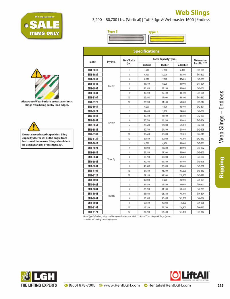
Master Link 400T Master Link
Material: Grade 80 Safety factor: ≤ 12914000 – 400 ton, 5 times
> 12916000 – 400 ton, 4 times Standards: Generally according to EN 1677-4 Finish: Painted Temperature range: ≤ 12914000 – 400 ton, -4°F up to +392°F
> 12916000 – 400 ton, -40°F up to +392°F; Polar Rated Standard certification: Certificate of Conformity
3.1 material certificate EN 10204
Model WLL (ton)
MBL (ton)
A (in.)
B (in.)
C (in.)
Weight (lbs.)
12913500 400 2000 4 17/32 27 9/16 9 27/32 366
Specifications
Green shading reflects rental inventory.
Items onthis page are
availablefor rent.
AVA
ILABLE
FOR RENT

Rigging
211(800) 878-7305 www.RentLGH.com [email protected]
ROV
Shan
k Ho
ok
ROV Shank Hook ROV Shank Hook
Model Capacity (Tons) A B C D E F G H I J K L Weight
(lbs.)
53000080 80 3 13/16 5 1/2 16 7/16 5 3/16 37 13/32 3 15/16 3 3/8 8 1/4 4 3/16 4 23/32 11 13/32 15 11/32 245
Dimensions
Green shading reflects rental inventory.
Items onthis page are
availablefor rent.
AVA
ILABLE
FOR RENT

SlingsRigging
212 (800) 878-7305 www.RentLGH.com [email protected]
Slings Effect of Angle of Lift on a Sling Rated Capacity
Using slings at an angle can become deadly if that angle is not taken into consideration when selecting the sling to be used. The tension on each leg of the sling is increased as the angle of lift, from horizontal, decreases. It is most desirable for a sling to have a larger angle of lift, approaching 90°. Lifts with angles of less than 30° from horizontal are not recommended. If you can measure the angle of lift or the length and height of the sling as rigged, you can determine the properly rated sling for your lift.
Reduction Factor (RF)
Angle From Horizontal
Tension Factor (TF)
1.000 90° 1.000
0.996 85° 1.004
0.985 80° 1.015
0.966 75° 1.035
0.940 70° 1.064
0.906 65° 1.104
0.866 60° 1.155
0.819 55° 1.221
0.766 50° 1.305
0.707 45° 1.414
0.643 40° 1.555
0.574 35° 1.742
0.500 30° 2.000
Effect of Angle Chart
Sling capacity decreases as the angle from horizontal decreases.Sling angles of less than 30° are not recommended.
What would be the rating of each sling rigged at this angle?
1. Calculate the Reduction Factor [RF].• using the angle from horizontal, read across
the Angle Chart to the corresponding number of the Reduction Factor column.
– OR –• Divide sling height* [H] by sling length* [L]
2. Reduction Factor [RF] x the sling’s rated capacity for the type hitch that will be used = Sling’s Reduction Rating.
*Measured from a common horizontal plane to the hoisting hook
What capacity sling do I need?
1. Determine the weight that the sling will be lifting [LW].
2. Calculate the Tension Factor [TF].• using the angle from horizontal, read across
the Angle Chart to the corresponding number of Tension Factor column.
– OR –• Divide sling length* [L] by sling height* [H]
3. Lifting Weight [LW] x the Tension Factor [TF] = Minimum Sling Rating for the type of hitch that will be used.
*Measured from a common horizontal plane to the hoisting hook
Reduced Capacity Increasing Tension

Rigging
Web
Slin
gs
213(800) 878-7305 www.RentLGH.com [email protected]
Web Slings Standard Web Sling Types
Hardware SlingsUnilink and Web Trap – Hardware can help to extend sling life by protecting the webbing from abrasion on rough crane hooks. Hardware can often be reused, lowering sling replacement costs.Type U (UU) – Has the preferred and economical Unilink fitting on each end for use in a vertical, choker or basket hitch. Unilinks allow choking from either end to save time and vary wear points.Type 1 (TC) – Has a Web-Trap triangle and choker fitting on either end. Typical use is in a choker hitch. Can also be used in vertical and basket hitches.Type 2 (TT) – Has a Web-Trap triangle on each end. Normally used in a basket hitch, but can also be used in a vertical hitch. They cannot be used as a choker.
Eye TypeType 3 (EE) – Flat Eye slings are very popular and can be used in all three types of hitches. They are easier to remove from beneath the load than sling types 1,2 and 4. Unless type 4 is requested, type 3 will be supplied as the standard EE sling.Type 4 (EE) – Twisted Eye slings are similar to Type 3 except the eyes are turned 90° to form a better choker hitch. The eyes of a Type 4 nest better on the crane hook.
Endless TypeType 5 (EN) – Endless slings are versatile and the most economically priced. They can be used in all three types of hitches. The sling can be rotated to minimize wear. The sling legs can be spread for improved load balance.
Reverse Eye TypeType 6 (RE) – An endless sling with butted edges sewn together to double the sling width. They have reinforced eyes and wear pads on both sides of body and eyes. The result is an extremely strong and durable sling.
Type of Webbing
Approximate Thickness
(in)
Relative Strength/Width
Factor APrice/Strength
Factor B Advantages
Webmaster 1600 3/16 100% 100% Webmaster webs are the industry standard.
Webmaster 1200 1/8 75% 105% Wider bearing surface per capacity.
Tuff-Edge 3/16 100% 105% Tuff-Edge fights edge abrasion and cutting – the #1 cause of web sling damage.
Dura-Web 2000 5/16 125% 114% Up to 30% better against cuts.
Dura-Web 1000 3/16 62.5% 137% Dura-Web lasts 25% longer against surface abrasion
Lift-All Web Selector – Quick Comparisons
Factor A – Relative strength factor. This column compares the strength of the various webs to Webmaster 1600 in the same widths.Factor B – Price to strength comparison. This column compares the relative cost per capacity of the various webs to Webmaster
1600 using a 2” x 10’ Type 3 sling.
This page containsThis page contains
ITEMS ONLYITEMS ONLYSALESALE
Type U
Type 1
Type 2
Type 3
Type 4
Type 5
Type 6

Web Slings – Eye-to-Eye
Rigging
214 (800) 878-7305 www.RentLGH.com [email protected]
Ply Qty.Sling Width (In.)
1 2 3 4 6 8 10 121 8 1/2 10 11 16 20 24 24
2 8 1/2 10 11 12 16 20 24 24
3 10 12 14 16 18 24 24 24
4 10 12 14 16 18 24 24 24
Eye Length (Applies to all Web Slings)
Web Slings 1,600 – 59,500 Lbs. (Vertical) | Tuff Edge & Webmaster 1600 | Eye-to-Eye
Model Ply Qty. Web Width (in.)Rated Capacity* (lbs.) Webmaster
Part No. ***Vertical Choker V. Basket
EE1-801T
One Ply
1 1,600 1,280 3,200 EE1-801
EE1-802T 2 3,200 2,500 6,400 EE1-802
EE1-803T 3 4,800 3,800 9,600 EE1-803
EE1-804T 4 6,400 5,000 12,800 EE1-804
EE1-806T 6 9,600 7,700 19,200 EE1-806
EE1-808T 8 12,800 10,200 25,600 EE1-808
EE1-810T 10 16,000 12,800 32,000 EE1-810
EE1-812T 12 19,200 15,400 38,400 EE1-812
EE2-801T
Two Ply
1 3,200 2,500 6,400 EE2-801
EE2-802T 2 6,400 5,000 12,800 EE2-802
EE2-803T 3 8,800 7,040 17,600 EE2-803
EE2-804T 4 11,500 9,200 23,000 EE2-804
EE2-806T 6 16,500 13,200 33,000 EE2-806
EE2-808T 8 19,200 15,400 38,400 EE2-808
EE2-810T 10 22,400 17,900 44,800 EE2-810
EE2-812T 12 26,900 21,500 53,800 EE2-812
EE3-801T
Three Ply
1 4,100 3,300 8,200 EE3-801
EE3-802T 2 8,300 6,600 16,600 EE3-802
EE3-803T 3 12,500 10,000 25,000 EE3-803
EE3-804T 4 16,000 12,800 32,000 EE3-804
EE3-806T 6 23,000 18,400 46,000 EE3-806
EE3-808T 8 30,700 24,500 61,400 EE3-808
EE3-810T 10 36,800 29,400 73,600 EE3-810
EE3-812T 12 44,000 35,200 88,000 EE3-812
EE4-801T
Four Ply
1 5,000 4,000 10,000 EE4-801
EE4-802T 2 10,000 8,000 20,000 EE4-802
EE4-803T 3 14,900 11,900 29,800 EE4-803
EE4-804T 4 19,800 15,800 39,600 EE4-804
EE4-806T 6 29,800 23,800 59,600 EE4-806
EE4-808T 8 39,700 31,700 79,400 EE4-808
EE4-810T 10 49,600 39,600 99,200 EE4-810
EE4-812T 12 59,500 47,600 119,000 EE4-812
Specifications
Note: Tapering-Types 3 and 4 slings are tapered at 3” and wider unless otherwise specified. *** Add a “D” to sling code for polyester.*** Add a “D” to sling code for polyester.
This page containsThis page contains
ITEMS ONLYITEMS ONLYSALESALE
Type 3 (Flat Eye) Type 3 (Flat Eye)
Type 4 (Twisted Eye) Type 4 (Twisted Eye)
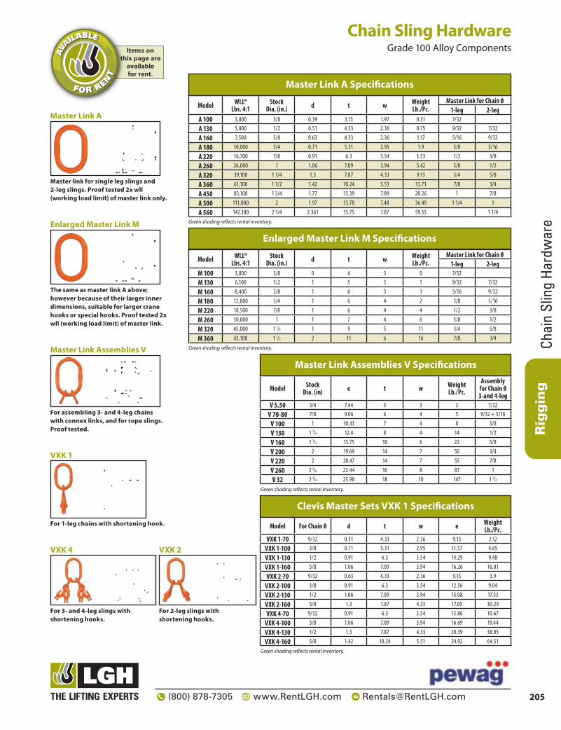
Always use Wear Pads to protect synthetic slings from
being cut by load edges.
Do not exceed rated capacities. Sling capacity decreases as the angle from horizontal decreases. Slings should not be used at angles of less than 30°.
Rigging
Web
Slin
gs –
End
less
215(800) 878-7305 www.RentLGH.com [email protected]
Model Ply Qty. Web Width (in.)
Rated Capacity* (lbs.) Webmaster Part No. ***Vertical Choker V. Basket
EN1-801T
One Ply
1 3,200 2,500 6,400 EN1-801
EN1-802T 2 6,400 5,000 12,800 EN1-802
EN1-803T 3 8,800 7,040 17,600 EN1-803
EN1-804T 4 11,500 9,200 23,000 EN1-804
EN1-806T 6 16,500 13,200 33,000 EN1-806
EN1-808T 8 19,200 15,400 38,400 EN1-808
EN1-810T 10 22,400 17,900 44,800 EN1-810
EN1-812T 12 26,900 21,500 53,800 EN1-812
EN2-801T
Two Ply
1 6,200 4,900 12,400 EN2-801
EN2-802T 2 12,400 9,900 24,800 EN2-802
EN2-803T 3 16,300 13,000 32,600 EN2-803
EN2-804T 4 20,700 16,500 41,400 EN2-804
EN2-806T 6 28,600 23,000 57,200 EN2-806
EN2-808T 8 30,700 24,500 61,400 EN2-808
EN2-810T 10 33,600 26,800 67,200 EN2-810
EN2-812T 12 37,600 30,000 75,200 EN2-812
EN3-801T
Three Ply
1 8,000 6,400 16,000 EN3-801
EN3-802T 2 16,000 12,800 32,000 EN3-802
EN3-803T 3 21,500 17,200 43,000 EN3-803
EN3-804T 4 28,700 23,000 57,400 EN3-804
EN3-806T 6 40,700 32,500 81,400 EN3-806
EN3-808T 8 46,000 36,800 92,000 EN3-808
EN3-810T 10 51,500 41,200 103,000 EN3-810
EN3-812T 12 59,200 47,300 118,400 EN3-812
EN4-801T
Four Ply
1 10,000 8,000 20,000 EN4-801
EN4-802T 2 19,800 15,800 39,600 EN4-802
EN4-803T 3 26,700 21,300 53,400 EN4-803
EN4-804T 4 35,600 28,400 71,200 EN4-804
EN4-806T 6 50,500 40,400 101,000 EN4-806
EN4-808T 8 57,600 46,000 115,200 EN4-808
EN4-810T 10 67,200 53,700 134,400 EN4-810
EN4-812T 12 80,700 64,500 161,400 EN4-812
Specifications
Note: Type 5 (Endless) slings are Not tapered unless specified. *** Add a “D” to sling code for polyester.***Add a “D” to sling code for polyester.
Web Slings 3,200 – 80,700 Lbs. (Vertical) | Tuff Edge & Webmaster 1600 | Endless
This page containsThis page contains
ITEMS ONLYITEMS ONLYSALESALE
Always use Wear Pads to protect synthetic slings from being cut by load edges.
Type 5Type 5
Do not exceed rated capacities. Sling capacity decreases as the angle from horizontal decreases. Slings should not be used at angles of less than 30°.

Nylon W
eb SlingsRigging
216 (800) 878-7305 www.RentLGH.com [email protected]
Web Slings 1,600 – 53,700 Lbs. (Vertical) | Type 3 – Flat Eye & Type 4 – Twisted Eye | Eye-to-Eye
This page containsThis page contains
ITEMS ONLYITEMS ONLYSALESALE
Width Model Ply Qty.
Rated Capacity In Pounds
Inside Eye Size Laying
Flat
Weight In LBSVertical Choker Basket
5’ Base add/ft
6” 96EE1 1 9,600 7,700 19,200 12” 2.78 0.33
6” 96EE2 2 16,300 13,000 32,600 15” 3.78 0.662
6” 96EE3 3 23,000 18,400 46,000 18” 5.71 0.993
6” 96EE4 4 32,600 24,500 65,200 18” 7.65 1.32
8” 98EE1 1 12,800 10,200 25,600 18” 4.06 0.47
8” 98EE2 2 22,000 17,600 44,000 18” 5.45 0.96
8” 98EE3 3 33,000 24,750 66,000 24” 8.18 1.41
8” 98EE4 4 44,000 33,000 88,000 24” 10.9 1.88
10” 910EE1 1 16,000 12,800 32,000 18” 5.23 0.596
10” 910EE2 2 24,000 19,200 48,000 18” 7.05 1.19
10” 910EE3 3 36,000 28,800 72,000 24” 10.65 1.78
10” 910EE4 4 48,000 38,400 96,000 24” 14.25 2.38
12” 912EE1 1 19,200 15,360 38,400 24” 6.45 0.734
12” 912EE2 2 26,900 21,500 53,800 24” 8.67 1.47
12” 912EE3 3 40,320 32,250 90,640 30” 13.33 2.2
12” 912EE4 4 53,700 43,000 107,400 30” 18 2.93
Heavy Duty (900 Webbing) 6”-12”
NOTE: Standard eye construction is Type 3 flat eyes When requiring twisted eyes, must specify Type 4 Tapered eyes on all sling widths 3” and larger
NOTE: Angles of less than 30° will not be used. REFER TO ANGLE EFFICIENCY CHART
Width Model Ply Qty.
Rated Capacity In Pounds
Inside Eye Size Laying
Flat
Weight In LBSVertical Choker Basket
5’ Base add/ft
1” 91EE1 1 1,600 1200 3,200 9” 0.42 0.056
1” 91EE2 2 3,200 2,600 6,400 9” 0.68 0.112
1” 91EE3 3 4,100 3,300 8,200 9” 1 0.16
1” 91EE4 4 5,500 4,400 11,000 9” 1.3 0.224
2” 92EE1 1 3,200 2,500 6,400 9” 0.84 0.11
2” 92EE2 2 6,400 5,100 12,800 9” 1.3 0.22
2” 92EE3 3 8,200 6,600 16,400 12” 1.9 0.33
2” 92EE4 4 11,000 8,800 22,000 12” 2.5 0.44
3” 93EE1 1 4,800 3,800 9,600 12” 1.4 0.18
3” 93EE2 2 8,900 7,200 17,800 12” 2.16 0.35
3” 93EE3 3 12,300 9,900 24,600 15” 3.13 0.52
3” 93EE4 4 17,800 14,400 35,600 15” 4.1 0.7
4” 94EE1 1 6,400 5,100 12,800 12” 1.75 0.222
4” 94EE2 2 11,500 9,200 23,000 12” 2.45 0.444
4” 94EE3 3 15,300 12,200 30,600 15” 3.85 0.666
4” 94EE4 4 23,000 18,000 46,000 15” 5.2 0.888
5” 95EE1 1 8,000 6,400 16,000 12” 2.46 0.274
5” 95EE2 2 13,600 10,900 27,200 15” 3.28 0.548
5” 95EE3 3 19,000 15,000 38,000 18” 4.8 0.822
5” 95EE4 4 27,200 20,400 54,400 18” 6.35 1.09
Heavy Duty (900 Webbing) 1”-5”
NOTE: Standard eye construction is Type 3 flat eyes When requiring twisted eyes, must specify Type 4 Tapered eyes on all sling widths 3” and larger
NOTE: Angles of less than 30° will not be used. REFER TO ANGLE EFFICIENCY CHART

Rigging
Wire
Rop
e
217(800) 878-7305 www.RentLGH.com [email protected]
Wire Rope General Information
Rope Diameter (in) Approx. Weight per Foot (lbs.)
Nominal Breaking Strength (tons)
1/4 .12 3.40
5/16 .18 5.27
3/8 .26 7.55
7/16 .35 10.2
1/2 .46 13.3
9/16 .59 16.8
5/8 .72 20.6
3/4 1.04 29.4
7/8 1.42 39.8
1 1.85 51.7
1 1/8 2.34 65.0
1 1/4 2.89 79.9
1 3/8 3.50 96.0
1 1/2 4.16 114
1 5/8 4.8 132
1 3/4 5.67 153
1 7/8 6.50 174
2 7.39 198
Specifications
Note: Specialty ropes are available upon request.
This page containsThis page contains
ITEMS ONLYITEMS ONLYSALESALE
Wire Core 6 x 19 Class
Extra Improved Plow Steel (EIP) Higher
Capacities
Six Strand Ropes Having 9 to 26 Wires Per Strand Better
Abrasion Resistance
Wire Core 6 x 37 Class
Extra Improved Plow Steel (EIP) Higher
Capacities
Six Strand Ropes Having 27 to 49
Wires Per Strand More Flexible
Wire RopeThese high quality wire ropes are available in cut lengths or by the reel.
6 x 19
6 x 37
Rope Dia. (in) Approx. Weight per Foot (lbs.)
Nominal Breaking Strength (tons)
3/8 .25 6.15
7/16 .35 8.33
1/2 .45 10.8
9/16 .58 13.6
5/8 .71 16.8
3/4 1.02 24.0
7/8 1.39 32.5
1 1.82 42.2
1 1/8 2.3 53.1
Rotation Resistant Wire Rope
Note: Specialty ropes are available upon request.
19 x 7
6 x 19 and 6 x 37 Class Wire Rope

Wire Rope Slings
Rigging
218 (800) 878-7305 www.RentLGH.com [email protected]
Wire Rope Slings General Information
How to order wire rope slingsSpecify:1. Rope Diameter – inches2. Sling Length – Feet (Bearing point to bearing point3. Description of rope construction class – 6 x 19 etc.4. Attachments – Master link, Hook, etc.Tolerances and Minimum LengthsRefer to tables for tolerances and minimum lengths.Wire Rope ClassStandard rope classes are shown for each type and size of sling in the charts. Specific rope constructions are available upon request.
This page containsThis page contains
ITEMS ONLYITEMS ONLYSALESALE
Standard Combinations
Eye & Eye
Eye & Thimble
Eye & Hook
Thimble & Crescent Thimble
Thimble & Slip-Thru Thimble
Crescent Thimble & Hook
Crescent Thimble & Crescent ThimbleEye & Thimble
Sliding Choker
Eye & EyeSlip-Thru Thimble & Hook
Slip-Thru Thimble & Slip-Thru Thimble
Eye & Crescent Thimble
Eye & Slip-Thru Thimble
Thimble & Hook
Thimble & Thimble
Acknowledgement Lift-All wire rope slings and rated capacities comply with all OSHA, ASME B30.9, and Wire Rope Technical Board publications. Portions of this section of the catalog were taken from the Wire Rope Sling User’s Manual with the permission of the Wire Rope Technical Board and the American Iron and Steel Institute. Note: Proof testing with certification available for all slings at an additional charge.

Rigging
Wire
Rop
e Sl
ings
219(800) 878-7305 www.RentLGH.com [email protected]
Wire Rope Slings .65 – 130 Ton (Vertical) | IWRC 6x19 & 6x36 EIPS | Mechanical Splice
With Single Part Body Permaloc
Wire Rope Class
Rope Dia. (in)
EIP, IWRC
**Min. Sling
Length
Standard Eye Size
(in) W x L
Thimbled Eye Size
(in) W x LEye Hook
Cap. (tons)
Crescent Thimble Eye Size
(in) W x L
Slip Thru Thimble Eye Size
(in) W x L
Sliding Choker
Hook (in)
*Rated Capacity (tons)
Vertical ChokerVertical Basket
6 x 19 EIP, IWRC
1/4 .65 .48 1.3 1’ 6” 2 x 4 7/8 x 1 5/8 1 2 x 4 2 1/8 x 4 1/8 3/8
5/16 1.0 .74 2.0 1’ 9” 2 1/2 x 5 1 1/16 x 1 7/8 1 2 x 4 2 1/8 x 4 1/8 3/8
3/8 1.4 1.1 2.9 2’ 3 x 6 1 1/8 x 2 1/8 1 1/2 2 x 4 2 1/8 x 4 1/8 3/8
7/16 1.9 1.4 3.9 2’ 3” 3 1/2 x 7 1 1/4 x 2 1/4 2 2 x 5 2 3/8 x 4 3/8 1/2
1/2 2.5 1.9 5.1 2’ 6” 4 x 8 1 1/2 x 2 3/4 3 2 1/4 x 6 2 3/8 x 4 3/8 1/2
9/16 3.2 2.4 6.4 2’ 9” 4 1/2 x 9 1 1/2 x 2 3/4 4 1/2 2 1/4 x 7 2 3/8 x 4 3/8 5/8
5/8 3.9 2.9 7.8 3’ 5 x 10 1 3/4 x 3 1/4 4 1/2 2 3/4 x 7 3 3/8 x 6 5/8 5/8
3/4 5.6 4.1 11 3’ 6” 6 x 12 2 x 3 3/4 7 3 1/4 x 8 1/2 3 3/8 x 6 5/8 3/4
7/8 7.6 5.6 15 4’ 7 x 14 2 1/4 x 4 1/4 11 4 1/2 x 10 3 3/4 x 7 1/8 7/8
1 9.8 7.2 20 4’ 6” 8 x 16 2 1/2 x 4 1/2 11 4 1/2 x 11 1/2 3 3/4 x 7 1/8 1
1 1/8 12 9.1 24 5’ 9 x 18 2 7/8 x 5 1/8 15 4 7/8 x 13 4 3/8 x 8 3/8 1 1/8
6 x 37 EIP, IWRC
1 1/4 15 11 30 5’ 6” 10 x 20 3 1/2 x 6 1/2 15 5 1/2 x 14 1/2 4 3/8 x 8 3/8 1 1/4
1 3/8 18 13 36 6’ 11 x 22 3 1/2 x 6 1/4 22 6 x 16 5 x 9 1/2 1 3/8
1 1/2 21 16 42 7’ 12 x 24 3 1/2 x 6 1/4 22 6 x 17 1/2 5 x 9 1/2 1 1/2
1 3/4 28 21 57 8’ 14 x 28 4 1/2 x 9 30 7 x 20 6 3/4 x 11 3/4 —
2 37 28 73 9’ 16 x 32 6 x 12 37 7 x 23 1/2 8 x 14 1/2 —
2 1/4 44 35 89 10’ 18 x 36 7 x 14 45 8 1/2 x 26 8 x 15 1/2 —
2 1/2 54 42 109 11’ 20 x 40 — 60 8 1/2 x 29 1/2 — —
2 3/4 65 51 130 12’ 22 x 44 — — — — —
3 77 60 153 13’ 24 x 48 — — — — —
3 1/2 102 79 203 16.5’ 32 x 64 — — — — —
3 3/4 115 90 229 18’ 36 x 72 — — — — —
4 130 97 259 24’ 45 x 90 — — — — —
Specifications
Note: Larger diameter slings available. Basket ratings are based on a minimum D/d of 25.* 1 Ton = 2,000 lbs.** Minimum sling length when using standard eyes.Green shading reflects rental inventory.
Mechanically swaged, flemish eye splice wire rope slings.
Do not exceed rated capacities. Sling capacity decreases as the angle from horizontal decreases. Slings should not be used at angles of less than 30°.
Items onthis page are
availablefor rent.
AVA
ILABLE
FOR RENT

Wire Rope Slings
Rigging
220 (800) 878-7305 www.RentLGH.com [email protected]
Permaloc Bridle Slings
(With Single Part Body)
Rope Dia. (in.) **Min.
Sling Length
Eye Hook Cap. (tons)
*Rated Capacity (tons) Oblong Link
Stock Dia
* Rated Capacity (tons) Oblong Link
Stock Dia
* Rated Capacity (tons) Oblong Link
Stock Dia
60° 45° 30° 60° 45° 30° 60° 45° 30°
1/4 1’ 3” 1 1.1 .91 .65 1/2 1.7 1.4 .97 1/2 2.2 1.8 1.3 1/2
5/16 1’ 6” 1 1.7 1..4 1.0 1/2 2.6 2.1 1.5 1/2 3.5 2.8 2.0 3/4
3/8 1’ 8” 1 1/2 2.5 2.0 1.4 1/2 3.7 3.0 2.2 3/4 5.0 4.1 2.9 3/4
7/16 1’ 10” 2 3.4 2.7 1.9 3/4 5.0 4.1 2.9 3/4 6.7 5.5 3.9 1
1/2 2’ 3 4.4 3.6 2.5 3/4 6.6 5.4 3.8 1 8.8 7.1 5.1 1
9/16 2’ 2” 4 1/2 5.5 4.5 3.2 3/4 8.3 6.8 4.8 1 11 9.0 6.4 1 1/4
5/8 2’ 4” 4 1/2 6.8 5.5 3.9 1 10 8.3 5.9 1 1/4 14 11 7.8 1 1/4
3/4 2’ 9” 7 9.7 7.9 5.6 1 1/4 15 12 8.4 1 1/2 19 16 11 1 3/4
7/8 3’ 3” 11 13 11 7.6 1 1/4 20 16 11 1 1/2 26 21 15 1 3/4
1 3’ 6” 11 17 14 9.8 1 1/2 26 21 15 1 3/4 34 28 20 2 1/4
1 1/8 4’ 15 21 17 12 1 1/2 31 26 18 1 3/4 42 34 24 2 3/4
1 1/4 4’ 6” 15 26 21 15 1 3/4 38 31 22 2 51 42 30 2 3/4
1 3/8 5’ 22 31 25 18 1 3/4 46 38 27 2 1/4 — — — —
1 1/2 5’ 6” 22 37 30 21 2 55 45 32 2 1/4 — — — —
1 3/4 6’ 6” 30 49 40 28 2 1/4 — — — — — — — —
2 8’ 37 63 52 37 2 3/4 — — — — — — — —
Specifications
This page containsThis page contains
SALEITEMS ONLYSALE
ITEMS ONLY
Wire Rope Slings 1.1 – 63 Ton (Rated @ 60 Deg.) | IWRC 6x19 & 6x37 EIPS | Mechanical Splice Bridle Sling
Note: Length Tolerances - Single Part Wire Rope Slings - Standard length tolerance is plus or minus two rope diameters, or plus or minus 0.5% of the sling length, whichever is greater. The legs of bridle slings, or matched slings are normally held to within one rope diameter.*1 Ton = 2,000 lbs.** Minimum length based on thimbled eye and eye hook.
6 x
19 E
IP, I
WRC
6 x
37 E
IP, I
WRC

Rigging
Wire
Rop
e Sl
ings
221(800) 878-7305 www.RentLGH.com [email protected]
Wire Rope Slings .54 – 7.4 Ton (Vertical) | IWRC 6x19 EIP - GAC 7 x 19 | Hidden Tucked – Multi-Part
This page containsThis page contains
SALEITEMS ONLYSALE
ITEMS ONLY
Do not exceed rated capacities. Sling capacity decreases as the angle from horizontal decreases. Slings should not be used at angles of less than 30°.
Wire Rope Class
Rope Dia. (in) EIP, FC
Min. Sling Length
Standard Eye Size (in) W x LRated Capacity (tons)
Vertical Choker Vertical Basket
1/4 .54 .42 1.1 2’ 3 x 6
5/16 .83 .66 1.7 2’ 3” 3 x 6
3/8 1.2 .94 2.4 2’ 6” 3 x 6
7/16 1.6 1.3 3.2 2’ 9” 3 1/2 x 7
1/2 2.0 1.6 4.0 3’ 4 x 8
9/16 2.5 2.1 5.0 3’ 6” 4 1/2 x 9
5/8 3.1 2.6 6.2 4’ 5 x 10
3/4 4.3 3.7 8.6 4’ 6” 6 x 12
7/8 5.7 5.0 11 5’ 6” 7 x 14
1 7.4 6.4 15 6’ 8 x 16
Specifications
Basket ratings are based on a minimum D/d of 15.
6 x 19 EIP, FC

Wire Rope Slings
Rigging
222 (800) 878-7305 www.RentLGH.com [email protected]
Wire Rope Slings 1.2 – 18 Ton (Vertical) | IWRC 6x19 EIP - GAC 7 x 19 | Hidden Tucked – Multi-Part
This page containsThis page contains
ITEMS ONLYITEMS ONLYSALESALE
Do not exceed rated capacities. Sling capacity decreases as the angle from horizontal decreases. Slings should not be used at angles of less than 30°.
7 x 7 x 19 7 x 6 x 19
Component Rope Dia. (in.)
Sling Body Dia. (in.)
Rated Capacity (tons)
Min. Sling Length
Standard Eye (in.)
W x L
Crescent Thimble Eye Size
(in.) W x L
Slip Thru Thimble Eye Size
(in.) W x LVertical Choker Vertical
1/8 3/8 1.3 .91 2.6 2’ 3 x 6 2 x 4 2 1/8 x 4 1/8
3/16 9/16 2.8 1.9 5.6 2’ 6” 4 x 8 2 1/4 x 6 2 3/8 x 4 3/8
1/4 3/4 4.7 3.2 9.3 3’ 5 x 10 2 3/4 x 7 3 3/8 x 6 5/8
5/16 15/16 6.5 4.5 13 3’ 6” 6 x 12 3 1/4 x 8 1/2 3 3/4 x 7 1/8
3/8 1 1/8 9.6 6.6 19 4’ 7 1/2 x 15 4 1/2 x 10 3 3/4 x 7 1/8
7/16 1 5/16 14 9.3 27 4’ 6” 9 x 18 4 7/8 x 13 4 3/8 x 8 3/8
1/2 1 1/2 18 12 35 5’ 10 x 20 5 1/2 x 14 1/2 4 3/8 x 8 3/8
7 Part Cable Specifications
Basket ratings are based on minimum D/d of 10.
7 x
19 G
AC
6 x
19
3 x 7 x 19 3 x 6 x 19
Component Rope Dia. (in.)
Sling Body Dia. (in.)
Rated Capacity (tons)
Min. Sling Length
Standard Eye (in.)
W x L
Crescent Thimble Eye Size
(in.) W x L
Slip Thru Thimble Eye Size
(in.) W x LVertical Choker Vertical
Basket
3/16 3/8 1.2 .82 2.4 2’ 3 x 6 2 x 4 2 1/8 x 4 1/8
1/4 1/2 1.9 1.3 3.9 2’ 6” 4 x 8 2 1/4 x 4 2 3/8 x 4 3/8
5/16 5/8 3.0 2.1 6.0 3’ 5 x 10 2 3/4 x 5 3 3/8 x 6 5/8
3/8 3/4 4.3 2.9 8.6 3’ 6” 6 x 12 3 1/4 x 6 3 3/8 x 6 5/8
7/16 7/8 5.8 4.0 12 4’ 7 x 14 4 1/2 x 9 3 3/4 x 7 1/8
1/2 1 7.6 5.2 15 4’ 6” 8 x 16 4 1/2 x 9 3 3/4 x 7 1/8
9/16 1 1/8 9.6 6.6 19 5’ 9 x 18 4 7/8 x 10 4 3/8 x 8 3/8
5/8 1 1/4 12 8.0 23 5’ 6” 10 x 20 5 1/2 x 11 4 3/8 x 8 3/8
3/4 1 1/2 17 11 34 7’ 11 x 22 6 x 12 5 x 9 1/2
3 Part Cable Specifications
Basket ratings are based on a minimum D/d of 10.
7 x
19 G
AC
6 x
19 E
IP, I
WRC

Rigging
Wire
Rop
e Sl
ings
223(800) 878-7305 www.RentLGH.com [email protected]
Wire Rope Slings .84 – 33 Ton (Vertical) | IWRC 6x19 EIP - GAC 7 x 19 | Hidden Tucked – Multi-Part
This page containsThis page contains
ITEMS ONLYITEMS ONLYSALESALE
Do not exceed rated capacities. Sling capacity decreases as the angle from horizontal decreases. Slings should not be used at angles of less than 30°.
Component Rope Dia. (in.)
Sling Body Dia. (in.)
Rated Capacity (tons)
Min. Sling Length
Standard Eye (in.)
W x L
Crescent Thimble Eye Size
(in.) W x L
Slip Thru Thimble Eye Size
(in.) W x LVertical Choker Vertical
Basket
1/8 9/16 1.1 1.0 2.2 2’ 3 x 6 2 x 4 2 1/8 x 4 1/8
3/16 13/16 2.4 2.1 4.7 3’ 4 x 8 2 1/4 x 6 2 3/8 x 4 3/8
1/4 1 1/8 3.9 3.4 7.8 3’ 6” 5 x 10 3 1/4 x 8 3 3/8 x 6 5/8
5/16 1 3/8 5.5 4.8 11 4’ 6” 6 x 12 4 1/2 x 10 3 3/4 x 7 1/8
3/8 1 11/16 8.1 7.1 16 5’ 7 x 14 4 5/8 x 12 3 3/4 x 7 1/8
7/16 2 11 10 23 6’ 8 x 16 5 1/2 x 14 4 3/8 x 8 3/8
1/2 2 1/4 15 13 30 6’ 6” 9 x 18 6 x 16 5 x 9 1/2
9/16 2 1/2 19 16 38 7’ 10 x 20 6 1/2 x 18 5 x 9 1/2
5/8 2 13/16 23 20 46 8’ 11 x 22 7 x 20 6 3/4 x 11 3/4
3/4 3 3/8 33 29 66 9’ 12 x 24 8 x 24 8 x 14 1/2
6 Part Cable Specifications
Basket ratings are based on a minimum D/d of 25.
7 x
19 G
AC
6 x 19
EIP,
IWRC
8 x 7 x 19 8 x 6 x 19
6 x 7 x 19 6 x 6 x 19
Component Rope Dia. (in.)
Sling Body Dia. (in.)
Rated Capacity (tons)
Min. Sling Length
Standard Eye (in.)
W x L
Crescent Thimble Eye Size
(in.) W x L
Slip Thru Thimble Eye Size
(in.) W x LVertical Choker Vertical
Basket
1/8 9/16 x 3/8 .84 .74 1.7 2’ 3 x 6 2 x 4 2 1/8 x 4 1/8
3/16 13/16 x 1/2 1.8 1.5 3.5 3’ 4 x 8 2 1/4 x 7 2 3/8 x 4 3/8
1/4 1 1/8 x 11/16 2.9 2.6 5.9 3’ 6” 5 x 10 3 1/4 x 8 1/2 3 3/8 x 6 5/8
5/16 1 3/8 x 7/8 4.1 3.6 8.2 4’ 6” 6 x 12 4 1/2 x 11 1/2 3 3/8 x 6 5/8
3/8 1 11/16 x 1 6.0 5.3 12 5’ 7 x 14 4 7/8 x 13 3 3/4 x 7 1/8
7/16 2 x 1 3/16 8.6 7.5 17 6’ 8 x 16 6 x 16 3 3/4 x 7 1/8
1/2 2 1/4 x 1 3/16 11 9.8 22 6’ 6” 9 x 18 6 x 17 1/2 4 3/8 x 8 3/8
9/16 2 1/2 x 1 1/2 14 12 28 7’ 10 x 20 7 x 20 4 3/8 x 8 3/8
5/8 2 13/16 x 1 11/16 17 15 35 8’ 11 x 22 7 x 23 1/2 5 x 9 1/2
3/4 3 3/8 x 2 25 22 49 9’ 12 x 24 8 1/2 x 26 6 3/4 x 11 3/4
6 Part Cable Specifications
Basket ratings are based on a minimum D/d of 25.
7 x 19
GAC
6 x 19
EIP,
IWRC

Wire Rope Slings
Rigging
224 (800) 878-7305 www.RentLGH.com [email protected]
Composed of 9 Parts of EIP Rope
Actual Finished
DiameterEye Length
Rated Capacity (tons)Approximate Wt./Ft. Lbs.Vertical Choker Vertical
Basket
9x6x19
3/4” 3” 30“ 42 31 83 9.36
7/8” 3 1/2” 35“ 56 42 112 12.78
1” 4” 40“ 74 55 146 16.65
1 1/8” 4 1/2” 45“ 92 69 184 21.06
9x6x37
1 1/4” 5” 50“ 115 86 230 26.01
1 3/8” 5 1/2” 55“ 137 102 273 31.50
1 1/2” 6” 60“ 164 123 328 37.44
1 3/4” 7” 70“ 220 155 440 51.03
2” 8” 80“ 280 210 560 66.51
2 1/4” 9” 90“ 355 266 711 84.24
2 1/2” 10” 100“ 428 321 856 104.00
2 3/4” 11” 110” 485 — 970 140.00
9 Part Braided Wire Rope Sling Specifications
Green shading reflects rental inventory.
Wire Rope Slings 42 – 1,224 Ton (Vertical) | IWRC 6x19 & 6x37 | 9-Part Braided
Diameter Component
PartsBody Finished
Diameter
Rated Capacity (tons)Approximate Wt./Ft. Lbs.Vertical Choker Vertical
Basket5/8” 2 1/2” 59 42 118 6.48
3/4” 3” 85 59 170 9.36
7/8” 3 1/2” 115 81 230 13
1” 4” 148 104 296 17
1 1/8” 4 1/2” 187 131 374 21
1 1/4” 5” 230 161 460 26
1 3/8“ 5 1/2” 276 194 552 32
1 1/2” 6” 328 230 656 38
1 3/4” 7” 441 308 882 51
2” 8” 570 399 1140 67
2 1/4” 9” 711 498 1422 84
2 1/2“ 10“ 870 609 1740 104
2 3/4“ 11“ 1040 728 2080 126
3“ 12“ 1224 857 2448 150
9 Part Braided Endless Wire Rope Sling/Grommet Specifications
Green shading reflects rental inventory.
Items onthis page are
availablefor rent.
AVA
ILABLE
FOR RENT

Rigging
Wire
Rop
e Sl
ings
225(800) 878-7305 www.RentLGH.com [email protected]
Sling Weights (Approx.) To estimate sling weights, multiply length x Per Foot Weight and add Zero Base Weight plus
any additional fittings’ weights.
Wire Rope Slings Sling WeightsItems on
this page areavailablefor rent.
AVA
ILABLE
FOR RENT
Rope Dia. (in)
*Zero Base Weight (lbs.)
Per Foot Weight
1/4 .31 .12
5/16 .47 .18
3/8 .73 .26
7/16 1.3 .35
1/2 1.7 .46
9/16 3.1 .59
5/8 3.5 .72
3/4 5.7 1.0
7/8 8.9 1.4
1 13 1.9
1 1/8 18 2.3
1 1/4 25 2.9
1 3/8 32 3.5
1 1/2 41 4.2
1 3/4 65 5.7
2 99 7.4
2 1/4 169 9.4
2 1/2 278 12
2 3/4 — 14
3 — 16.6
3 1/2 — 22.7
3 3/4 — 26
4 — 44
Specifications
* Zero Base Weight accounts for the additional rope and sleeves required to form two standard eyes.
Green shading reflects rental inventory.

Ratchet & U
tility Straps - Hooks & Hardw
areRigging
226 (800) 878-7305 www.RentLGH.com [email protected]
Ratchet & Utility Straps - Hooks & Hardware Hardware & Fittings (Used with Tiedowns)
This page containsThis page contains
ITEMS ONLYITEMS ONLYSALESALE
Product Model Description Breaking Strength
Working Load Limit
C5 1” Light Duty Cam 700 lbs. 265 lbs.
C112 1” Heavy Duty Cam 1,500 lbs. 500 lbs.
02 1” D-Ring 5,000 lbs. 1,665 lbs.
04 1” Vinyl S-Hook 1,500 lbs. 500 lbs.
07A 1” Flat Snap-Hook 1,500 lbs. 500 lbs.
12 1” LD Boat Hook 4,000 lbs. 1,335 lbs.
13 1” Snap Hook 3,750 lbs. 1,250 lbs.
15 1” Wire Hook 3,000 lbs. 1,000 lbs.
5001 1” LD Ratchet 1,780 lbs. 590 lbs.
5003 1” HD Ratchet 3,000 lbs. 1,000 lbs.
Hardware / Fittings For 1” Utility Straps
Note: Capacity/WLL ratings are only as strong as their weakest components or attachments.
Product Model Description Breaking Strength Working Load Limit
22 2” Wire Hook 5,000 lbs. 1,665 lbs.
24 2” Narrow Flat Hook 5,000 lbs. 1,665 lbs.
25 2” STD Flat Hook 10,000 lbs. 3,335 lbs.
26 2” Flat Side Snap Hook 5,000 lbs. 1,665 lbs.
27 2” Twisted Snap Hook 11,000 lbs. 3,665 lbs.
27A 2” HD Flat SideSnap Hook 11000 lbs. 3665 lbs.
28 2” Flat D-Ring 11,000 lbs. 3,665 lbs.
29 2” Forged Snap Hook 10,000 lbs. 3,335 lbs.
30 3 PC. Cluster Hook 11,600 lbs. 3,900 lbs.
31 2”-4” Pear-Grab Hook 16,200 lbs. 5,400 lbs.
32 2”-4” Chain Anchor 10,000 lbs. 3,335 lbs.
36 3”-4” Flat Hook 15,000 lbs. 5,000 lbs.
37 3”-4” Delta Ring 20,000 lbs. 6,670 lbs.
38 2” D-Ring 5,000 lbs. 1,665 lbs.
382 3/8” Dia. Round Ring 5,000 lbs. 1,665 lbs.
40 3”-4” HD Wire Hook 22,000 lbs. 7,335 lbs.
5035 2” LD Ratchet 4,000 lbs. 1,335 lbs.
5065 2” Short Ratchet 10,000 lbs. 3,335 lbs.
5130LH 2” Long Ratchet 10,000 lbs. 3,335 lbs.
5150 3” Ratchet 22,000 lbs. 7,335 lbs.
5200 4” Ratchet 24,000 lbs. 8,000 lbs.
Hardware / Fittings For 2” – 4” Ratchet Straps
Note: Capacity/WLL ratings are only as strong as their weakest components or attahments.

Rigging
Poly
este
r Rou
ndsl
ings
227(800) 878-7305 www.RentLGH.com [email protected]
Roundslings 2,600 – 90,000 Lbs. (Vertical) | EN SeriesItems on
this page areavailablefor rent.
AVA
ILABLE
FOR RENT
How To Measure
Length<
Code Color
Rated Capacity (lbs.)
Minimum Length (ft)
Approximate Measurements
Vertical Choker Basket
Weight (lbs. / ft)
Body Dia. Relaxed (in)
Width at Load (in)
Minimum Hardware
Dia* (in)
EN30 Purple 2,600 2,100 5,200 1 1/2 .2 5/8 1 7/16
EN60 Green 5,300 4,200 10,600 1 1/2 .3 7/8 1 3/8 5/8
EN90 Yellow 8,400 6,700 16,800 3 .5 1 1/8 1 3/4 3/4
EN120 Tan 10,600 8,500 21,200 3 .6 1 1/8 1 7/8 7/8
EN150 Red 13,200 10,600 26,400 3 .8 1 3/8 2 1
EN180 White 16,800 13,400 33,600 3 .9 1 3/8 2 1/8 1 1/8
EN240 Blue 21,200 17,000 42,400 3 1.3 1 3/4 2 5/8 1 3/16
EN360 Grey 31,000 24,800 62,000 3 1.7 2 1/4 3 1/4 1 1/2
EN600 Brown 53,000 42,400 106,000 8 2.8 2 3/4 4 2
EN800 Olive 66,000 52,800 132,000 8 3.4 3 1/8 4 5/8 2 1/8
EN1000 Black 90,000 72,000 180,000 8 4.3 3 5/8 5 1/4 2 1/2
Specifications
Green shading reflects rental inventory.
Do not exceed rated capacities. Sling capacity decreases as the angle from horizontal decreases. Slings should not be used at angles of less than 30°.

Polyester RoundslingsRigging
228 (800) 878-7305 www.RentLGH.com [email protected]
Roundslings 6,700 – 229,500 Lbs. (Vertical) | B6E Series | 6-Part Braided
How To Measure
ED EL
Length
< <
<
<
<
<
W
<
<
Items onthis page are
availablefor rent.
AVA
ILABLE
FOR RENT
Do not exceed rated capacities. Sling capacity decreases as the angle from horizontal decreases. Slings should not be used at angles of less than 30°.
Model Color
Rated Capacity (lbs.)
Minimum Length (ft.)
Approximate Measurements
Vertical Choker Basket
Weight (lbs. / ft.)
Standard Eye Length (EL)
(in.)
Width at Load
(W) (in.)
Thickness at Load (in.)
Eye Dia. (ED) (in.)
Minimum Hardware Dia* (in.)
B6E30 Purple 6,700 5,300 13,400 4 1/2 .8 15 3 1/4 3/4 1 3/4 5/8
B6E60 Green 13,500 10,800 27,000 5 1.2 15 3 3/4 1 1/8 2 1
B6E90 Yellow 21,400 17,100 42,800 5 1/2 1.6 15 4 1/4 1 1/4 2 1 1/4
B6E120 Tan 27,000 21,600 54,000 5 1/2 2.0 15 4 1/2 1 5/16 2 1/4 1 3/8
B6E150 Red 33,600 26,800 67,200 6 1/2 2.7 20 5 1/4 1 3/4 2 1/2 1 1/2
B6E180 White 42,800 34,200 85,600 7 3.2 20 5 1/2 2 2 3/4 1 3/4
B6E240 Blue 54,000 43,200 108,000 9 4.4 20 6 5/8 2 1/4 3 1/2 1 3/4
B6E360 Grey 79,000 63,200 158,000 9 1/2 6.5 30 8 1/4 2 1/2 4 1/4 2 1/2
B6E600 Brown 135,100 108,000 270,200 10 1/2 9.7 30 11 2 3/4 5 3
B6E800 Olive 168,300 134,600 336,600 13 12.0 30 12 4 5 1/4 3 1/2
B6E1000 Black 229,500 183,600 459,000 14 1/2 15.6 31 13 1/2 4 1/2 5 3/4 4
Specifications
* This is the smallest recommended connection hardware diameter to be used for a vertical hitch.Green shading reflects rental inventory.
How To Measure
ED EL
Length
< <
<
<
<
<
W
<
<
How To Measure
ED EL
Length
< <
<
<
<
<
W
<
<
How To Measure
ED EL
Length
< <
<
<
<
<
W
<
<

Rigging
Poly
este
r Rou
ndsl
ings
229(800) 878-7305 www.RentLGH.com [email protected]
Roundslings 8,800 – 306,000 Lbs. (Vertical) | B8E Series | 8-Part BraidedItems on
this page areavailablefor rent.
AVA
ILABLE
FOR RENT
Model Color
Rated Capacity (lbs.)
Minimum Length (ft.)
Approximate Measurements
Vertical Choker Basket
Weight (lbs. / ft.)
Standard Eye Length
(EL) (in.)
Width at Load
(W) (in.)
Thickness at Load
(in.)Eye Dia. (ED) (in.)
Minimum Hardware Dia* (in.)
B8E30 Purple 8,800 7,100 17,600 4 1/2 1.1 15 3 1/2 1 1 3/4 3/4
B8E60 Green 18,000 14,400 36,000 5 1.5 15 4 1 3/8 2 1 1/8
B8E90 Yellow 28,500 22,800 57,000 5 1/2 2.2 15 4 3/4 1 5/8 2 1/2 1 1/2
B8E120 Tan 36,000 28,800 72,000 5 1/2 2.6 15 5 1 3/4 2 1/2 1 1/2
B8E150 Red 44,900 35,900 89,800 6 1/2 3.6 20 6 2 1/8 2 3/4 1 3/4
B8E180 White 57,100 45,600 114,200 7 4.1 20 6 1/4 2 1/2 3 1/4 2
B8E240 Blue 72,000 57,600 144,000 9 5.6 20 7 1/2 2 3/4 3 3/4 2
B8E360 Grey 105,400 84,300 210,800 9 1/2 8.3 30 9 1/2 3 1/4 4 1/2 2 1/2
B8E600 Brown 180,200 144,100 360,400 10 1/2 12.0 30 13 3 3/4 5 1/2 3 1/2
B8E800 Olive 224,400 179,500 448,800 13 16.0 30 13 1/2 4 1/2 6 4
B8E1000 Black 306,000 244,000 612,000 14 1/2 20.0 31 15 3/4 5 1/4 6 1/2 4 3/4
8 Part Round Braid (B8E) Specifications
Green shading reflects rental inventory.
Always use Wear Pads to protect synthetic slings from being cut by load edges.
Do not exceed rated capacities. Sling capacity decreases as the angle from horizontal decreases. Slings should not be used at angles of less than 30°.

RoundslingsRigging
230 (800) 878-7305 www.RentLGH.com [email protected]
Roundslings 10,000 – 200,000 Lbs. (Vertical) | KEN Series | KeyFlex Items on
this page areavailablefor rent.
AVA
ILABLE
FOR RENT
Model
Rated Capacity (lbs.)
Minimum Length (ft.)
Approximate Measurements
Vertical Choker Basket
Weight (lbs. / ft.)
Body Dia. Relaxed
(in.)
Width at Load
(W) (in.)
Minimum Hardware Dia* (in.)
KEN10K 10,000 8,000 20,000 3 .3 1 1 9/16 11/16
KEN15K 15,000 12,000 30,000 3 .5 1 1/8 1 3/4 7/8
KEN20K 20,000 16,000 40,000 3 .6 1 1/4 2 1 1/16
KEN25K 25,000 20,000 50,000 3 .7 1 1/4 2 1/8 1 1/4
KEN30K 30,000 24,000 60,000 8 .8 1 3/8 2 1/8 1 7/16
KEN40K 40,000 32,000 80,000 8 1.0 1 3/4 2 3/4 1 1/2
KEN50K 50,000 40,000 100,000 10 1.2 1 7/8 2 7/8 1 3/4
KEN60K 60,000 48,000 120,000 10 1.5 2 3 1/8 2
KEN70K 70,000 56,000 140,000 10 1.7 2 1/8 3 1/4 2 3/16
KEN80K 80,000 64,000 160,000 10 1.8 2 1/4 3 1/2 2 3/8
KEN90K 90,000 72,000 180,000 10 2.1 2 1/2 3 7/8 2 3/8
KEN100K 100,000 80,000 200,000 10 2.6 2 3/4 4 1/4 2 1/2
KEN125K 125,000 100,000 250,000 10 3.0 3 4 7/8 2 5/8
KEN150K 150,000 120,000 300,000 10 3.5 3 1/4 5 1/4 2 7/8
KEN175K 175,000 140,000 350,000 10 4.0 3 1/2 5 3/4 3 1/8
KEN200K 200,000 160,000 400,000 10 4.5 3 3/4 6 1/8 3 3/8*-
KeyFlex Capacities and Measurements
Green shading reflects rental inventory.

Rigging
Shac
kles
231(800) 878-7305 www.RentLGH.com [email protected]
Working Load Limit
Diameter Bow
Diameter Pin
Diameter Eye Width Eye Width
InsideLength Inside
Width Bow Length Length
Bolt Width Weight Each
tons a mm
b mm
c mm
d mm
e mm
f mm
g mm
h mm
i mm
j mm kg
0.33. 5 6 12 5 9.5 22 16 36 29.5 26 0.020.5 7 8 16.5 7 12 29 20 48.5 38 34 0.05
0.75 9 10 20 9 13.5 32 22 56 46.5 40 0.11 10 11 22.5 10 17 36.5 26 63.5 54 46 0.14
1.5 11 13 26.5 11 19 43 29 74 59.5 51 0.192 13.5 16 34 13 22 51 32 89 73 58 0.36
3.25 16 19 40 16 27 64 43 110 89 75 0.634.75 19 22 46 19 31 76 51 129 103 89 1.016.5 22 25 52 22 36 83 58 144 119 102 1.58.5 25 28 59 25 43 95 68 164 137 118 2.219.5 28 32 66 28 47 108 75 185 153 131 3.1612 32 35 72 32 51 115 83 201 170 147 4.31
13.5 35 38 80 35 57 133 92 227 186 162 5.5517 38 42 88 38 60 146 99 249 203 175 7.4325 45 50 103 45 74 178 126 300 243 216 12.8435 50 57 111 50 83 197 138 331 272 238 18.15
42.5 57 65 130 57 95 222 160 377 310 274 26.2955 65 70 145 65 105 260 180 433 344 310 37.6
Specifications (mm)
Green shading reflects rental inventory.
G-4161
Material: bow and pin high tensile steel, Grade 6, quenched and tempered
Safety Factor: MBL equals 6 x WLL
Standard: En 13889 and meets performance requirements of US Fed. Spec. RR-C-271 Type IVA Class 2, Grade A
Finish: hot dipped galvanized
Temperature Range: -20°C up to +200° C
Certificates: at no extra charges this product can be supplied with a works certificate, certificate of basic raw material, manufacturer test certificate and/or EC Declaration of Conformity.
Shackles .33 – 55 Ton | Screw Pin
Working Load Limit
Diameter Bow
Diameter Pin
Diameter Eye Width Eye Width
InsideLength Inside
Width Bow Length Length
BoltWidth Bow
Weight Each
tons a in.
b in.
c in.
d in.
e in.
f in.
g in.
h in.
i in.
j in. lbs.
0.33. 3/16 1/4 1/2 3/16 3/8 7/8 5/8 1 13/32 1 5/32 1 1/32 0.05
0.5 1/4 5/16 21/32 9/32 15/32 1 5/32 25/32 2 29/32 1 1/2 1 11/32 0.11
0.75 5/16 3/8 25/32 11/32 17/32 1 1/4 7/8 2 7/32 1 27/32 1 9/16 0.22
1 3/8 7/16 7/8 13/32 21/32 1 7/16 1 1/32 2 1/2 2 1/8 1 13/16 0.3
1.5 7/16 1/2 1 1/32 7/16 3/4 1 11/16 1 5/32 2 29/32 2 11/32 2 0.42
2 1/2 5/8 1 11/32 1/2 7/8 2 1 1/4 3 1/2 2 7/8 2 9/32 0.79
3.25 5/8 3/4 1 9/16 5/8 1 1/16 2 17/32 1 11/16 4 11/32 3 1/2 2 15/16 1.38
4.75 3/4 7/8 1 13/16 3/4 1 7/32 3 2 5 3/32 4 1/16 3 1/2 2.22
6.5 7/8 1 2 1/16 7/8 1 13/32 3 9/32 2 9/32 5 21/32 4 11/16 4 1/32 3.31
8.5 1 1 1/8 2 5/16 31/32 1 11/16 3 3/4 2 11/16 6 15/32 5 13/32 4 21/32 4.86
9.5 1 1/8 1 1/4 2 19/32 1 3/32 1 27/32 4 1/4 2 15/16 7 9/32 6 1/32 5 5/32 6.97
12 1 1/4 1 3/8 2 27/32 1 1/4 2 4 17/32 3 9/32 7 29/32 6 11/16 5 25/32 9.49
13.5 1 3/8 1 1/2 3 5/32 1 3/8 2 1/4 5 1/4 3 5/8 8 15/16 7 5/16 6 3/8 12.24
17 1 1/2 1 5/8 3 15/32 1 1/2 2 3/8 5 3/4 3 29/32 9 13/16 8 6 7/8 16.37
25 1 3/4 2 4 1/16 1 25/32 2 29/32 7 4 31/32 11 13/36 9 9/16 8 1/2 28.31
35 2 2 1/4 4 3/8 1 31/32 3 9/32 7 3/4 5 7/16 13 1/32 10 23/32 9 3/8 40.01
42.5 2 1/4 2 9/16 5 1/8 2 1/4 3 3/4 8 3/4 6 5/16 14 27/32 12 7/32 10 25/32 57.96
55 2 1/2 2 3/4 5 23/32 2 9/16 4 1/8 10 1/4 7 3/32 17 1/16 13 17/32 12 7/32 82.89
Specifications (in.)
Green shading reflects rental inventory.
Items onthis page are
availablefor rent.
AVA
ILABLE
FOR RENT

Rigging
Shackles
232 (800) 878-7305 www.RentLGH.com [email protected]
Working load limit
Diameter bow
Diameter pin
Diameter eye
Width eye
Width inside
Length inside
Width bow Length Length
bolt Width Thickness nut
Weight each
tons a mm
b mm
c mm
d mm
e mm
f mm
g mm
h mm
i mm
j mm
k mm kg
0.5 7 8 16.5 7 12 29 20 48.5 42 34 4 0.130.75 9 10 20 9 13.5 32 22 56 50 40 5 0.25
1 10 11 22.5 10 17 36.5 26 63.5 60 46 8 0.341.5 11 13 26.5 11 19 43 29 74 67 51 11 0.482 13.5 16 34 13 22 51 32 89 82 58 13 0.92
3.25 16 19 40 16 27 64 43 110 98 75 17 1.624.75 19 22 46 19 31 76 51 129 114 89 19 2.596.5 22 25 52 22 36 83 58 144 130 102 22 3.98.5 25 28 59 25 43 95 68 164 150 118 25 5.699.5 28 32 66 28 47 108 75 185 166 131 27 8.0612 32 35 72 32 51 115 83 201 178 147 30 10.81
13.5 35 38 80 35 57 133 92 227 197 162 33 14.4217 38 42 88 38 60 146 99 249 202 175 19 18.0625 45 50 103 45 74 178 126 300 249 216 23 31.3435 50 57 111 50 83 197 138 331 269 238 26 43.77
42.5 57 65 130 57 95 222 160 377 301 274 29 62.4655 65 70 145 65 105 260 180 433 330 310 32 87.2785 75 83 162 73 127 329 190 527 380 340 39 136.69
Specifications (mm)
Green shading reflects rental inventory.
G-4163
G-4163
G-4163
Shackles 0.5 – 85 Ton | Bolt Type
Material: bow and pin high tensile steel, Grade 6, quenched and tempered
Safety Factor: MBL equals 6 x WLL
Standard: En 13889 and meets performance requirements of US Fed. Spec. RR-C-271 Type IVA Class 3, Grade A
Finish: hot dipped galvanized
Temperature Range: -20°C up to +200° C
Certificates: at no extra charges this product can be supplied with a works certificate, certificate of basic raw material, manufacturer test certificate and/or EC Declaration of Conformity
Working load limit
Diameter bow
Diameter pin
Diameter eye
Width eye
Width inside
Length inside
Width bow Length Length
bolt Width Thickness nut
Weight each
tons a in.
b in.
c in.
d in.
e in.
f in.
g in.
h in.
i in.
j in.
k in. lbs.
0.5 1/4 5/16 21/32 9/32 15/32 1 5/32 25/32 1 29/32 1 21/32 1 11/32 5/32 0.130.75 5/16 3/8 25/32 11/32 17/32 1 1/4 7/8 2 7/32 1 31/32 1 9/16 3/16 0.25
1 3/8 7/16 7/8 13/32 21/32 1 7/16 1 1/32 2 1/2 2 3/8 1 13/16 5/16 0.341.5 7/16 1/2 1 1/32 7/16 3/4 1 11/16 1 5/32 2 29/32 2 5/8 2 7/16 0.482 1/2 5/8 1 11/32 1/2 7/8 2 1 1/4 3 1/2 3 7/32 2 9/32 1/2 0.92
3.25 5/8 3/4 1 9/16 5/8 1 1/16 2 17/32 1 11/16 4 11/32 3 27/32 2 15/16 21/32 1.624.75 3/4 7/8 1 13/16 3/4 1 7/32 3 2 5 3/32 4 1/2 3 1/2 3/4 2.596.5 7/8 1 2 1/16 7/8 1 13/32 3 9/32 2 9/32 5 21/32 5 1/8 4 1/32 7/8 3.98.5 1 1 1/8 2 5/16 31/32 1 11/16 3 3/4 2 11/16 6 15/32 5 29/32 4 21/32 31/32 5.699.5 1 1/8 1 1/4 2 19/32 1 3/32 1 27/32 4 1/4 2 15/16 7 9/32 6 17/32 5 5/32 1 1/16 8.0612 1 1/4 1 3/8 2 27/32 1 1/4 2 4 17/32 3 9/32 7 29/32 7 5 25/32 1 3/16 10.81
13.5 1 3/8 1 1/2 3 5/32 1 3/8 2 1/4 5 1/4 3 5/8 8 15/16 7 3/4 6 3/8 1 5/16 14.4217 1 1/2 1 5/8 3 15/32 1 1/2 2 3/8 5 3/4 3 29/32 9 13/16 7 15/16 6 7/8 3/4 18.0625 1 3/4 2 4 1/16 1 25/32 2 29/32 7 4 31/32 11 13/16 9 13/16 8 1/2 29/32 31.3435 2 2 1/4 4 3/8 1 31/32 3 9/32 7 3/4 5 7/16 13 1/32 10 19/32 9 3/8 1 1/32 43.77
42.5 2 1/4 2 9/16 5 1/8 2 1/4 3 3/4 8 3/4 6 5/16 14 27/32 11 27/32 10 23/32 1 5/32 62.4655 2 1/2 2 3/4 5 23/32 2 9/16 4 1/8 10 1/4 7 3/32 17 1/16 13 12 7/32 1 1/4 87.2785 3 3 1/4 6 3/8 2 7/8 5 12 15/16 7 15/32 20 3/4 14 31/32 13 3/8 1 17/32 136.69
Specifications (in.)
Green shading reflects rental inventory.
Items onthis page are
availablefor rent.
AVA
ILABLE
FOR RENT

Rigging
Shac
kles
233(800) 878-7305 www.RentLGH.com [email protected]
Working load limit
Diameter bow
Diameter pin
Diameter eye
Width eye
Width inside
Length inside
Width bow Length Length
bolt Width Thickness nut
Weight each
tons a mm
b mm
c mm
d mm
e mm
f mm
g mm
h mm
i mm
j mm
k mm kg
120 95 95 208 91 147 400 238 647 440 428 50 243
150 105 108 238 102 169 410 275 688 490 485 60 353
200 120 130 279 113 179 513 290 838 520 530 60 518
250 130 140 299 118 205 554 305 904 560 565 65 628
300 140 150 325 123 205 618 305 996 575 585 70 750
400 170 175 376 164 231 668 325 1,114 690 665 70 1,235
500 180 185 398 164 256 718 350 1,190 720 710 70 1,510
600 200 205 444 189 282 718 375 1,243 810 775 70 1,940
700 210 215 454 204 308 718 400 1,263 870 820 70 2,161
800 210 220 464 204 308 718 400 1,270 870 820 70 2,425
900 220 230 485 215 328 718 420 1,296 920 860 70 2,822
1000 240 240 515 215 349 718 420 1,336 940 900 70 3,219
1250 260 270 585 230 369 768 450 1,456 1,025 970 70 4,387
1500 280 290 625 230 369 818 450 1,556 1,025 1,010 70 5,291
Specifications (mm)
Green shading reflects rental inventory.
P-6036
Material: bow and pin high tensile steel, Grade 8, quenched and tempered
Safety Factor: MBL equals 5 x WLL
Finish: hot dipped galvanized
Temperature Range: -20°C up to +200° C
Certificates: at no extra charges this product can be supplied with a works certificate,
certificate of basic raw material, manufacturer test certificate, EC Declaration of Conformity and all shackles starting from 150 tons are supplied with a Lloyd’s Register of Shipping Certificate on proof load
Note: +5% forging tolerance on inside width and length
Shackles 120 – 1,500 Ton | Alloy Bolt Type
Working load limit
Diameter bow
Diameter pin
Diameter eye
Width eye
Width inside
Length inside
Width bow Length Length
bolt Width Thickness nut
Weight each
tons a in.
b in.
c in.
d in.
e in.
f in.
g in.
h in.
i in.
j in.
k in. lbs.
120 3 3/4 3 3/4 8 3/16 3 19/32 5 25/32 15 3/4 9 3/8 25 15/32 17 5/16 16 27/32 1 31/32 243
150 4 1/8 4 1/4 9 3/8 4 1/32 6 21/32 16 5/32 10 13/16 27 3/32 19 9/32 19 3/32 2 3/8 353
200 4 23/32 5 1/8 10 31/32 4 7/16 7 1/16 20 3/16 11 13/32 33 20 15/32 20 7/8 2 3/8 518
250 5 1/8 5 1/2 11 25/32 4 21/32 8 1/16 21 13/16 12 35 19/32 22 1/16 22 1/4 2 9/16 628
300 5 1/2 5 29/32 12 25/32 4 27/32 8 1/16 24 11/32 12 39 7/32 22 5/8 23 1/32 2 3/4 750
400 6 11/16 6 7/8 14 13/16 6 15/32 9 3/32 26 5/16 12 25/32 43 27/32 27 5/32 26 3/16 2 3/4 1,235
500 7 3/32 7 9/32 15 21/32 6 15/32 10 3/32 28 9/32 13 25/32 46 27/32 28 11/32 27 15/16 2 3/4 1,510
600 7 7/8 8 1/16 17 15/32 7 7/16 11 3/32 28 9/32 14 3/4 48 15/16 31 7/8 30 1/2 2 3/4 1,940
700 8 9/32 8 15/32 17 7/8 8 1/32 12 1/8 28 9/32 15 3/4 49 23/32 34 1/4 32 9/32 2 3/4 2,161
800 8 9/32 8 21/32 18 9/32 8 1/32 12 1/8 28 9/32 15 3/4 50 34 1/4 32 9/32 2 3/4 2,425
900 8 21/32 9 1/16 19 3/32 8 15/32 12 29/32 28 9/32 16 17/32 51 1/32 36 7/32 33 27/32 2 3/4 2,822
1000 9 7/16 9 7/16 20 9/32 8 15/32 13 3/4 28 9/32 16 17/32 52 19/32 37 35 7/16 2 3/4 3,219
1250 10 1/4 10 5/8 23 1/32 9 1/16 14 17/32 30 1/4 17 23/32 57 5/16 40 11/32 38 3/16 2 3/4 4,387
1500 11 1/32 11 13/32 24 19/32 9 1/16 14 17/32 32 7/32 17 23/32 61 1/4 40 11/32 39 3/4 2 3/4 5,291
Specifications (in)
Green shading reflects rental inventory.
Items onthis page are
availablefor rent.
AVA
ILABLE
FOR RENT

Rigging
Shackles
234 (800) 878-7305 www.RentLGH.com [email protected]
Nominal Size (in.)
Working Load Limit*
(t)
Model Weight Each (lbs.)
G-209 Galv. S-209 S.C.
G-213 Galv.
S-213 S.C.
G-209 S-209
G-213 S-213
3/16 † 1/3 1018357 — — — .06 —1/4 1/2 1018375 1018384 1018017 1018026 .10 .13
5/16 3/4 1018393 1018400 1018035 1018044 .19 .183/8 1 1018419 1018428 1018053 1018062 .31 .29
7/16 1 1/2 1018437 1018446 1018071 1018080 .38 .381/2 2 1018455 1018464 1018099 1018106 .72 .715/8 3 1/4 1018473 1018482 1018115 1018124 1.37 1.503/4 4 3/4 1018491 1018507 1018133 1018142 2.35 2.327/8 6 1/2 1018516 1018525 1018151 1018160 3.62 3.49
1 8 1/2 1018534 1018543 1018179 1018188 5.03 5.001 1/8 9 1/2 1018552 1018561 1018197 1018204 7.41 6.971 1/4 12 1018570 1018589 1018213 1018222 9.50 9.751 3/8 13 1/2 1018598 1018605 1018231 1018240 13.53 13.251 1/2 17 1018614 1018623 1018259 1018268 17.20 17.251 3/4 25 1018632 1018641 1018277 1018286 27.78 29.46
2 35 1018650 1018669 1018295 1018302 45.00 45.752 1/2 † 55 1018678 1018687 — — 85.75 —
Specifications
Green shading reflects rental inventory.
Shackles .33 – 55 Ton | Screw Pin
• Shackles are Quenched and Tempered and can meet DNV impact requirements of 42 joules at -20°C.
• Working Load Limit permanently shown on every shackle.
• Forged – Quenched and Tempered, with alloy pins.
• Capacities 1/3 thru 55 metric tons.
• Look for the Red Pin®…the mark of genuine Crosby quality.
• Shackles can be furnished proof tested with certificates to designated standards, such as ABS, DNV, Lloyds, or other certification.
• Charges for proof testing and material certification available when requested at the time of order.
• Hot Dip galvanized or Self Colored.
• Fatigue rated.
G-209 S-209 G-213 S-213
Nominal Size (in.)
Working Load
Limit*(t)
Dimensions (in.) Tolerance + / -
A B C D E F G H L M N P C A3/16 † 1/3 .38 .25 .88 .19 .60 .56 .98 1.47 .16 1.12 — .19 .06 .061/4 1/2 .47 .31 1.13 .25 .78 .61 1.28 1.84 .19 1.38 1.34 .25 .06 .06
5/16 3/4 .53 .38 1.22 .31 .84 .75 1.47 2.09 .22 1.66 1.59 .31 .06 .063/8 1 .66 .44 1.44 .38 1.03 .91 1.78 2.49 .25 2.03 1.86 .38 .13 .06
7/16 1 1/2 .75 .50 1.69 .44 1.16 1.06 2.03 2.91 .31 2.38 2.13 .44 .13 .061/2 2 .81 .63 1.88 .50 1.31 1.19 2.31 3.28 .38 2.69 2.38 .50 .13 .065/8 3 1/4 1.06 .75 2.38 .63 1.69 1.50 2.94 4.19 .44 3.34 2.91 .69 .13 .063/4 4 3/4 1.25 .88 2.81 .75 2.00 1.81 3.50 4.97 .50 3.97 3.44 .81 .25 .067/8 6 1/2 1.44 1.00 3.31 .88 2.28 2.09 4.03 5.83 .50 4.50 3.81 .97 .25 .061 8 1/2 1.69 1.13 3.75 1.00 2.69 2.38 4.69 6.56 .56 5.07 4.53 1.06 .25 .06
1 1/8 9 1/2 1.81 1.25 4.25 1.16 2.91 2.69 5.16 7.47 .63 5.59 5.13 1.25 .25 .061 1/4 12 2.03 1.38 4.69 1.29 3.25 3.00 5.75 8.25 .69 6.16 5.50 1.38 .25 .061 3/8 13 1/2 2.25 1.50 5.25 1.42 3.63 3.31 6.38 9.16 .75 6.84 6.13 1.50 .25 .131 1/2 17 2.38 1.63 5.75 1.54 3.88 3.63 6.88 10.00 .81 7.35 6.50 1.62 .25 .131 3/4 25 2.88 2.00 7.00 1.84 5.00 4.19 8.86 12.34 1.00 9.08 7.75 2.25 .25 .13
2 35 3.25 2.25 7.75 2.08 5.75 4.81 9.97 13.68 1.22 10.34 8.75 2.40 .25 .132 1/2 † 55 4.13 2.75 10.50 2.71 7.25 5.69 12.87 17.84 1.38 13.00 — 3.13 .25 .25
Dimensions
+ Furnished in screw pin only.* Note: Maximum Proof Load is 2.0 times the working load limit. Minimum ultimate strength is 6 times the Working load limit.Green shading reflects rental inventory.
Items onthis page are
availablefor rent.
AVA
ILABLE
FOR RENT

Rigging
Shac
kles
235(800) 878-7305 www.RentLGH.com [email protected]
Items onthis page are
availablefor rent.
AVA
ILABLE
FOR RENT
Shackles .33 – 150 Ton | Bolt Type
• Working Load Limit permanently shown on every shackle.
• Forged – Quenched and Tempered, with alloy pins.
• Capacities 1/3 thru 55 metric tons.
• Look for the Red Pin®…the mark of genuine Crosby quality.
• Shackles 55 metric tons and smaller can be furnished proof tested with certificates to designated standards, such as ABS, DNV, Lloyds, or other certification.
• Certification must be requested at time of order.
• Shackles 85 metric tons and larger can be provided as follows: Non Destructive Tested, Serialized Pin and Bow, Material Certification (Chemical), Certification must be requested at time of order.
• Hot Dip galvanized or Self Colored.
• Fatigue rated.
G-2130 S-2130 G-2150 S-2150
Nominal Shackle Size
(in.)
Working Load Limit*
(t)
Model2130 Weight
Each (lbs.)2150 Weight
Each (lbs.)G-2130 Galv. S-2130 S.C. G-2150 Galv. S-2150
S.C.3/16 1/3** 1019464 — — — .06 —1/4 1/2 1019466 — 1019768 — .11 .13
5/16 3/4 1019468 — 1019770 — .22 .233/8 1 1019470 — 1019772 — .33 .33
7/16 1 1/2 1019471 — 1019774 — .49 .491/2 2 1019472 1019481 1019775 1019784 .79 .755/8 3 1/4 1019490 1019506 1019793 1019800 1.68 1.473/4 4 3/4 1019515 1019524 1019819 1019828 2.72 2.527/8 6 1/2 1019533 1019542 1019837 1019846 3.95 3.85
1 8 1/2 1019551 1019560 1019855 1019864 5.66 5.551 1/8 9 1/2 1019579 1019588 1019873 1019882 8.27 7.601 1/4 12 1019597 1019604 1019891 1019908 11.71 10.811 3/8 13 1/2 1019613 1019622 1019917 1019926 15.83 13.751 1/2 17 1019631 1019640 1019935 1019944 20.80 18.501 3/4 25 1019659 1019668 1019953 1019962 33.91 31.40
2 35 1019677 1019686 1019971 1019980 52.25 46.752 1/2 55 1019695 1019702 1019999 1020004 98.25 85.00
3 † 85** 1019711 — 1020013 — 154.00 124.253 1/2 † 120** 1019739 — — — 265.00 —
4 † 150** 1019757 — — — 338.00 —
Specifications
Green shading reflects rental inventory.
Nominal Shackle Size
(in.)
Working Load Limit*
(t)
Dimensions (in) Tolerance + / -
A B C D E F G H K L M N P R C & G A3/16 1/3** .38 .25 .88 .19 .60 .56 — 1.47 — .98 — .19 1.29 — .06 .061/4 1/2 .47 .31 1.13 .25 .78 .61 .75 1.84 1.59 1.28 .97 .25 1.56 .25 .06 .06
5/16 3/4 .53 .38 1.22 .31 .84 .75 1.00 2.09 1.91 1.47 1.16 .31 1.82 .31 .06 .063/8 1 .66 .44 1.44 .38 1.03 .91 1.22 2.49 2.30 1.78 1.41 .38 2.17 .38 .13 .06
7/16 1 1/2 .75 .50 1.69 .44 1.16 1.06 1.42 2.91 2.66 2.03 1.62 .44 2.51 .44 .13 .061/2 2 .81 .63 1.88 .50 1.31 1.19 1.63 3.28 3.03 2.31 1.81 .50 2.80 .50 .13 .065/8 3 1/4 1.06 .75 2.38 .63 1.69 1.50 2.00 4.19 3.75 2.94 2.31 .69 3.53 .63 .13 .063/4 4 3/4 1.25 .88 2.81 .75 2.00 1.81 2.38 4.97 4.53 3.50 2.75 .81 4.07 .81 .25 .067/8 6 1/2 1.44 1.00 3.31 .88 2.28 2.09 2.81 5.83 5.33 4.03 3.19 .97 4.71 .97 .25 .06
1 8 1/2 1.69 1.13 3.75 1.00 2.69 2.38 3.19 6.56 5.94 4.69 3.69 1.06 5.31 1.00 .25 .061 1/8 9 1/2 1.81 1.25 4.25 1.13 2.91 2.69 3.58 7.47 6.78 5.16 4.06 1.25 5.90 1.25 .25 .061 1/4 12 2.03 1.38 4.69 1.25 3.25 3.00 3.94 8.25 7.50 5.75 4.53 1.38 6.51 1.38 .25 .061 3/8 13 1/2 2.25 1.50 5.25 1.38 3.63 3.31 4.38 9.16 8.28 6.38 5.00 1.50 7.21 1.50 .25 .131 1/2 17 2.38 1.63 5.75 1.50 3.88 3.63 4.81 10.00 9.06 6.88 5.38 1.62 7.73 1.62 .25 .131 3/4 25 2.88 2.00 7.00 1.75 5.00 4.19 5.75 12.34 10.97 8.86 6.38 2.25 9.05 2.12 .25 .13
2 35 3.25 2.25 7.75 2.00 5.75 4.81 6.75 13.68 12.28 9.97 7.25 2.40 10.41 2.00 .25 .132 1/2 55 4.13 2.75 10.50 2.62 7.25 5.69 8.00 17.84 14.84 12.87 9.38 3.13 13.56 2.62 .25 .25
3 † 85** 5.00 3.25 13.00 3.00 7.88 6.50 8.50 21.50 16.88 14.36 11.00 3.62 16.50 3.50 .25 .253 1/2 † 120** 5.25 3.75 14.63 3.62 9.00 8.00 — 24.63 — 16.50 — 4.12 19.00 — .25 .25
4 † 150** 5.50 4.25 14.50 4.10 10.00 9.00 — 25.69 — 18.42 — 4.56 19.75 — .25 .25
Dimensions
*Note: Maximum Proof Load is 2.0 times the working load limit. Minimum ultimate strength is 6 times the working load limit.**Furnished in Anchor style only.+ Individually Proof Tested with certification and furnished with round head bolts with welded handles.

Rigging
Shackles
236 (800) 878-7305 www.RentLGH.com [email protected]
Nominal Shackle Size
(in.)Working Load
Limit* (t)Model 2130 Weight Each
(lbs.)G-2140 Galv. S-2140 S.C.
1 1/2 30 1021110 1021129 20.8
1 3/4 40 1021138 1021147 33.9
2 55 1021156 1021165 52.0
2 1/2 85 1021174 1021183 96.0
3 120 1021192 — 178.0
3 1/2 † 150 1021218 — 265.0
4 † 175 1021236 — 338.0
4 3/4** † 200 1021414 — 450.0
5** † 250 1021432 — 600.0
6** † 300 1021450 — 775.0
7** † 400 1021478 — 1,102.0
Specifications
Green shading reflects rental inventory.
Shackles 30 – 400 Ton | Alloy Bolt Type
• Shackles are Quenched and Tempered and can meet DNV impact requirements of 42 joules at -20°C.
• Working Load Limit is permanently shown on every shackle.
• Alloy bows, Alloy bolts.
• Quenched and Tempered.
• All sizes are individually proof tested to 2.0 times the Working Load Limit.
• Shackles 200 metric tons and larger are provided as follows.
• Non Destructive Tested.
• Serialized Pin and Bow.
• Material Certification (chemical).
• Certification must be requested at time of order.
• Forged Alloy Steel 30 thru 175 metric tons. Cast Alloy Steel 200 thru 400 metric tons.
• Pins are galvanized and painted red.
G-2140 S-2140
Nominal Shackle Size (in.)
Working Load Limit*
(t)
Dimensions (in.) Tolerance + / -
A B C D E F G H J K L A E
1 1/2 30 2.38 3.62 1.62 1.63 5.75 1.39 6.88 7.75 10.00 3.88 1.54 .13 .251 3/4 40 2.88 4.19 2.25 2.00 7.00 1.75 8.86 9.06 12.34 5.00 1.84 .13 .25
2 55 3.25 4.81 2.40 2.25 7.75 2.00 9.97 10.41 13.68 5.75 2.08 .13 .252 1/2 85 4.12 5.69 3.12 2.75 10.50 2.62 12.87 13.56 17.84 7.25 2.71 .25 .25
3 120 5.00 6.50 3.62 3.25 13.00 3.00 14.36 16.50 21.50 7.88 3.11 .25 .253 1/2 † 150 5.25 8.00 4.12 3.75 14.63 3.75 16.50 19.00 24.62 9.00 3.62 .25 .25
4 † 175 5.50 9.00 4.56 4.25 14.50 4.00 18.42 19.75 25.69 10.00 4.10 .25 .254 3/4** † 200 7.25 10.50 6.00 4.75 15.62 3.75 21.00 20.50 29.25 11.00 4.50 .25 .25
5** † 250 8.50 12.00 6.50 5.00 20.00 3.88 24.50 21.97 35.00 13.00 4.50 .25 .256** † 300 8.38 12.00 6.75 6.00 19.50 4.75 25.00 24.35 35.25 13.00 5.00 .25 .257** † 400 8.25 14.00 7.25 7.00 22.50 6.50 26.00 27.97 40.25 13.00 6.00 .25 .25
Dimensions
*Note: Maximum Proof Load is 2.0 times the working load limit. Minimum ultimate load is 4 times the working load limit on 200 thru 400 metric tons. For sizes 30 thru 175 metric tons, minimum ultimate load is 5.4 times the working load limit.
**Cast Alloy steel.+ Furnished with round head bolts with welded handle.Green shading reflects rental inventory.
Items onthis page are
availablefor rent.
AVA
ILABLE
FOR RENT

Rigging
Shac
kles
237(800) 878-7305 www.RentLGH.com [email protected]
Working Load Limit
(t)*G-2160 Model
Weight Each (lbs.)
Dimensions (in.)
A B +/- .25 C D +/- .02 E G H J K P R† 18 1021274 14.9 6.69 2.03 1.16 1.38 2.69 1.50 5.81 2.50 2.00 6.76 9.38† 30 1021575 25 7.73 2.37 1.38 1.63 3.50 2.50 7.00 3.13 2.50 8.50 11.38† 40 1021584 35 9.32 2.88 1.75 2.00 4.00 1.75 8.13 3.75 3.00 10.62 13.62† 55 1021593 71 10.41 3.25 2.00 2.27 4.63 2.00 9.42 4.50 3.50 12.26 15.63† 75 1021290 99 14.37 4.13 2.12 2.75 5.00 2.55 11.60 4.75 3.64 12.28 18.41
† 125 1021307 161 16.51 5.12 2.56 3.15 5.71 3.15 14.43 5.91 4.33 14.96 22.65† 200 1021316 500 20.67 5.91 3.35 4.12 7.28 4.33 18.98 8.07 5.41 19.49 29.82† 300 1021325 811 24.20 7.38 4.00 5.25 9.25 5.47 23.69 10.38 6.31 23.38 37.26
†† 400 1021334 1,041 30.06 8.66 5.16 6.30 11.81 6.30 22.71 12.60 7.28 27.17 38.78†† 500 1021343 1,378 32.99 9.84 5.59 7.09 12.52 6.69 24.88 13.38 8.86 31.10 42.71†† 600 1021352 1,833 35.39 10.83 6.04 7.87 13.78 7.28 27.64 14.56 9.74 34.06 47.24†† 700 1021361 2,446 38.91 11.81 6.59 8.46 14.80 7.87 29.04 15.74 10.63 37.01 50.17†† 800 1021254 3,016 43.50 12.80 7.19 9.06 15.75 8.27 29.62 16.54 10.92 38.39 52.09†† 900 1021389 3,436 43.60 13.78 7.78 9.84 16.93 8.66 30.02 17.32 11.51 40.35 54.04
†† 1000 1021370 4,022 45.98 14.96 8.33 10.63 17.72 9.06 30.02 18.12 12.11 43.32 55.32
Dimensions
*Ultimate load is 5 times the working load limit.+ Forged Alloy Steel. Proof load is 2 times the working load limit.++ Cast Alloy Steel. Proof load is 1.33 times the working load limit.Green shading reflects rental inventory.
G-2160
• All sizes Quenched and Tempered for maximum strength.
• Forged alloy steel from 30 through 300 metric tons.
• Cast alloy steel from 400 through 1,000 metric tons.
• Sizes 300 tons and smaller are proof tested to 2 times the Working Load Limit.
• Sizes 400 tons and larger are tested to 1.33 times Working Load Limit.
• All ratings are in metric tons, embossed on side of bow.
• Bows and pins are furnished Dimetcoted. All Pins are Dimetcoted then painted red.
• Greatly improves wearability of wire rope slings.
• Can be used to connect HIGH STRENGTH Synthetic Web Slings, HIGH STRENGTH Synthetic Round Slings or Wire Rope Slings.
• Increase in shackle bow radius provides minimum 58% gain in sling bearing surface and eliminates need for a thimble.
• Increases usable sling strength minimum of 15%.
• Pin is non-rotating, with weld on handles for easier use (300t and larger).
• All 2160 shackles are individually proof tested and magnetic particle inspected. Crosby certification available at time of order.
• Crosby products meet or exceed all the requirements of ASME B30.26 including identification, ductility, design factor, proof load and temperature requirements. Importantly, Crosby products meet other critical performance requirements including fatigue life, impact properties and material traceability, not addressed by ASME B30.26.
• Shackles requiring ABS, DNV, Lloyds and other certifications are available upon special request and must be specified at time of order.
• Shackles are produced in accordance with certified lifting appliance requirements.
• Non Destructive Testing. • Serialization / Identification. • Material Testing (Physical /
Chemical / Charpy). • Proof Testing.
Shackles 18 – 1,000 Ton | Wide BodyItems on
this page areavailablefor rent.
AVA
ILABLE
FOR RENT

Rigging
Shackles
238 (800) 878-7305 www.RentLGH.com [email protected]
Shackles 75 – 700 Ton | Bolt Type - Alloy Bolt Type - Wide Body
Working Load Limit
(ton)Type Weight
(lbs.)
Dimensions (in.)
A B C D E F G L R X Y
75 Wide Body 117 2 15/16 2 3/4 4 5/16 11 13/16 5 29/32 7 9/32 4 23/32 13 19/32 2 3/8 13 5/32 19 3/32
125 Wide Body 185 3 11/32 3 5/32 5 1/2 14 9/16 6 1/2 8 21/32 5 29/32 15 9/16 3 5/32 14 31/32 22 15/16
150 Wide Body 254 3 9/16 3 3/4 5 29/32 15 3/4 7 7/8 9 27/32 6 11/16 16 17/32 3 9/16 16 7/8 25 1/8
150 Bolt Type 353 4 4 1/4 6 11/16 15 3/4 9 1/16 10 13/16 — 18 11/16 — 18 7/8 26 13/32
175 Alloy-Bolt Type 331 4 4 1/4 5 1/2 15 3/4 9 1/16 9 27/32 — 17 5/16 — 17 23/32 26 11/32
400 Wide Body 1259 6 5/16 6 5/16 9 1/16 24 13/32 13 14 9/16 12 19/32 25 25/32 6 11/16 27 1/8 40 3/4
400 Bolt Type 1235 6 1/2 6 7/8 9 1/16 26 25/32 13 25/32 12 13/16 — 26 3/16 — 25 25/32 43 5/8
500 Wide Body 1585 6 11/16 7 3/32 10 7/16 26 25/32 13 25/32 17 23/32 13 3/8 27 15/16 7 3/32 30 11/16 44 9/32
600 Alloy-Bolt Type 1940 7 11/16 8 1/16 11 7/32 27 9/16 15 15/16 14 3/4 - 32 3/32 - 30 1/8 47 1/4
600 Wide Body 2116 7 3/32 7 7/8 11 13/32 28 11/32 15 15/16 19 9/32 14 9/16 31 5/16 7 15/32 33 11/32 47 3/4
700 Wide Body 2976 8 1/4 8 15/32 12 19/32 30 23/32 18 5/16 21 1/4 15 3/4 34 21/32 8 1/4 37 11/16 52 3/8
Dimensions
Green shading reflects rental inventory.
Items onthis page are
availablefor rent.
AVA
ILABLE
FOR RENTBolt Type Shackle Wide Body Shackle

Rigging
Swiv
els
239(800) 878-7305 www.RentLGH.com [email protected]
Swivel Hoist Ring 800 – 30,000 Lbs. | HR-125 Model | UNC Thread
Top washer has the following features:• The working Load limit and Recommended Torque value are
permanently stamped into each washer.• Washer is color coded for easy identification Red – UNC thread.
Bolt Size IdentificationThe size of the bolt will be stated as in the following example.Illustration shows meaning of each dimension given.
HR-125 Model
Working Load Limit*
(lbs.)Torque in Ft.
lbs.
Dimensions (in.)
Est. Weight Each (lbs.)Bolt Size ††
A
Effective Thread
Projection Length B
C D Radius E
Diameter F G H
1016887 † 800 7 5/16 – 18 x 1.50 .59 2.69 1.00 .46 .38 1.69 1.11 .43
1016898 † 1,000 12 3/8 – 16 x 1.50 .59 2.69 1.00 .46 .38 1.69 1.09 .43
1016909 2,500 28 1/2 – 13 x 2.00 .71 4.82 2.00 .88 .75 3.30 2.29 2.49
1016912 † 2,500 28 1/2 – 13 x 2.50 1.21 4.82 2.00 .88 .75 3.30 2.29 2.52
1016920 4,000 60 5/8 – 11 x 2.00 .71 4.82 2.00 .88 .75 3.30 2.21 2.55
1016924 † 4,000 60 5/8 – 11 x 2.75 1.46 4.82 2.00 .88 .75 3.30 2.21 2.70
1016931 5,000 100 3/4 – 10 x 2.25 .96 4.82 2.00 .88 .75 3.30 2.05 2.65
1016935 † 5,000 100 3/4 – 10 x 2.75 1.46 4.82 2.00 .88 .75 3.30 2.05 3.00
1016942 7,000 100 3/4 – 10 x 2.75 .90 6.55 3.00 1.37 1.00 4.73 2.98 7.00
1016946 † 7,000 100 3/4 – 10 x 3.50 1.65 6.55 3.00 1.37 1.00 4.73 2.98 7.00
1016953 8,000 160 7/8 – 9 x 2.75 .90 6.55 3.00 1.37 1.00 4.73 2.85 7.00
1016957 † 8,000 160 7/8 – 9 x 3.50 1.65 6.55 3.00 1.37 1.00 4.73 2.85 7.00
1016964 10,000 230 1 – 8 x 3.00 1.15 6.55 3.00 1.37 1.00 4.73 2.73 7.50
1016969 † 10,000 230 1 – 8 x 4.00 2.15 6.55 3.00 1.37 1.00 4.73 2.73 7.50
1016975 15,000 470 1 1/4 – 7 x 4.50 2.22 8.70 3.75 1.75 1.25 6.00 3.92 14.79
1016986 24,000 800 1 1/2 – 6 x 6.50 2.98 12.39 4.75 2.25 1.75 8.00 5.64 33.00
1016997 30,000 1,100 2 – 4 1/2 x 6.50 2.98 12.39 4.75 2.25 1.75 8.00 5.14 36.00
Specifications
*Ultimate load is 5 times the working load limit.+ Long bolts are designed to be used with soft metal (i.e. aluminum) work piece. While the long bolts may also be used with ferrous metal
(i.e. steel & iron) work piece, short bolts are designed for ferrous work pieces only.++ Bolt specification is a Grade 8 Alloy socket head cap screw to ASTM A574. All threads listed are UNC - 3A.
This page containsThis page contains
SALEITEMS ONLYSALE
ITEMS ONLY

Rigging
Swivels
240 (800) 878-7305 www.RentLGH.com [email protected]
Swivel Number (type) Model S.C. Working Load Limit*
(metric tons)Wire Rope Size
(in.)Weight Each
(lbs.)
3-S-1 297011 3 1/2 9.81
3-S-2 297020 3 1/2 9.63
3-S-3 297039 3 1/2 9.12
3-S-4 297048 3 1/2 9.00
3-S-5 297057 3 1/2 8.50
3-S-6 297066 3 1/2 9.32
5-S-1 297217 5 5/8 15.51
5-S-2 297226 5 5/8 13.69
5-S-3 297235 5 5/8 13.50
5-S-4 297244 5 5/8 12.33
5-S-5 297253 5 5/8 11.30
5-S-6 297262 5 5/8 14.24
8 1/2 -S -1 297413 8 1/2 3/4 29.42
8 1/2 -S -2 297422 8 1/2 3/4 26.16
8 1/2 -S -3 297431 8 1/2 3/4 24.90
8 1/2 -S -4 297440 8 1/2 3/4 29.00
8 1/2 -S -5 297459 8 1/2 3/4 29.25
8 1/2 -S -6 297468 8 1/2 3/4 32.00
10-S-1 297618 10 7/8 46.75
10-S-2 297627 10 7/8 45.75
10-S-3 297636 10 7/8 43.50
10-S-4 297645 10 7/8 44.00
10-S-5 297654 10 7/8 42.00
10-S-6 297663 10 7/8 45.50
15-S-1 297814 15 1 73.75
15-S-2 297823 15 1 62.75
15-S-3 297832 15 1 61.00
15-S-4 297841 15 1 61.00
15-S-5 297850 15 1 49.00
15-S-6 297869 15 1 63.00
25-S-1 298118 25 — 140.00
25-S-2 298127 25 — 140.00
25-S-3 298136 25 — 135.00
25-S-4 298145 25 — 135.00
25-S-5 298154 25 — 130.00
25-S-6 298163 25 — 135.00
35-S-1 298216 35 — 220.00
35-S-2 298225 35 — 155.00
35-S-3 298234 35 — 150.00
35-S-4 298243 35 — 150.00
35-S-5 298252 35 — 145.00
35-S-6 298261 35 — 215.00
45-S-1 298314 45 — 251.00
45-S-2 298323 45 — 235.00
45-S-3 298332 45 — 225.00
45-S-4 298341 45 — 225.00
45-S-5 298350 45 — 215.00
45-S-6 298369 45 — 270.00
Specifications
Green shading reflects rental inventory.Individually Proof of tested to 2 times the working load limit. Ultimate load is 5 times the working load limit.*LGH only stocks 5-2 Jaw & Jaw and S-3 Jaw & Eye for rental.
Swivels 3 – 45 Ton | S.C. Model Items on
this page areavailablefor rent.
AVA
ILABLE
FOR RENT
S-1 Jaw & Hook
S-6 Eye & Hook
S-2 Jaw & Jaw
S-4 Eye & Jaw
S-3 Jaw & Eye
S-5 Eye & Eye

Rigging
Swiv
els
241(800) 878-7305 www.RentLGH.com [email protected]
Swivels 3 – 45 Ton | S.C. Model
• Designed to swivel under load.• All swivels individually proof tested with certification.• All hooks furnished with latches assembled.• All jaws complete with bolts, nuts and cotter pins.• Pressure lube fitting provided.• NOT TO BE USED ON DEMOLITION (WRECKING) BALLS.• Other types and capacities up to 600 tons, available to meet your requirements.IMPORTANT – Crosby Swivels should only be used with the recommended wire rope. Contact the wire rope manufacturer for the proper wire rope to be used with Crosby Swivels.
Working Load Limit*
(metric tons)A B C D E F G H J K L M N P Q R S T V O
3 11.44 9.28 9.34 9.41 11.50 4.84 2.75 .75 .88 1.62 1.53 1.41 1.31 1.44 .75 1.03 1.12 1.25 1.13 1.00
5 13.34 10.31 10.06 9.81 13.09 6.28 3.00 .88 1.00 2.25 1.94 1.69 1.62 1.82 1.00 1.28 1.25 1.25 1.44 1.12
8 1/2 16.45 12.62 12.25 11.88 16.07 7.54 4.00 1.00 1.56 2.81 2.46 2.22 2.12 2.26 1.25 1.41 1.62 1.50 1.63 1.38
10 19.75 16.75 16.12 15.50 19.12 8.34 4.50 1.50 1.75 3.38 2.59 2.41 3.50 2.60 1.69 1.69 2.75 1.88 1.94 1.75
15 22.24 17.12 16.75 16.38 21.24 10.34 5.00 1.50 1.75 3.38 2.81 3.19 3.50 3.01 1.94 2.03 2.75 2.12 2.38 1.75
25 26.78 20.75 21.50 22.25 27.53 13.62 6.00 2.00 2.00 4.62 3.44 3.62 3.69 3.66 2.25 2.31 3.88 2.38 3.00 2.38
35 29.94 20.75 21.50 22.25 0.69 14.06 6.50 2.00 2.00 4.62 3.88 3.75 3.69 4.56 2.25 2.31 3.88 2.38 3.19 2.38
45 35.06 25.25 25.88 26.50 35.69 15.44 7.00 2.25 2.25 5.00 4.75 4.25 4.00 5.06 2.50 2.53 4.00 3.00 3.25 3.00
Dimensions
*Green shading reflects rental inventory.*Individually Proof tested to 2 times the working load limit. Ultimate load is 5 times the working load limit.* LGH only stocks S-2 Jaw & Jaw and S-3 Jaw & Eye for rental.
Items onthis page are
availablefor rent.
AVA
ILABLE
FOR RENT
S-3 Jaw & EyeS-1 Jaw & Hook S-2 Jaw & Jaw
S-4 Eye & Jaw S-5 Eye & Eye S-6 Eye & Hook

Rigging
Swivels
242 (800) 878-7305 www.RentLGH.com [email protected]
Model Number Weight A Overall Length
B Net Length
F Swivel Diameter
RE Pin to
Obstruction
SE Pin to End of
FittingT
Thickness of EyeU
Hole Diameter
Eye & Eye Swivels
3EEM 7 8 5.625 2.625 1.375 1.187 .875 1.062
4EE 16 11.875 9.375 3.250 1.875 1.375 1 1.312
7EE 16 11.875 9.375 3.250 1.875 1.375 1 1.312
12EE 30 15 11 4 2.750 2 1.250 1.781
19EE 34 15.500 11.500 4.437 2.375 2 1.250 1.781
25EE 44 17.750 13 5.250 2.875 2.375 1.625 2.093
30EE 91 20.125 14.625 6.500 2.750 2.750 1.750 2.312
Dimensions
Green shading reflects rental inventory.
12EE Eye & Eye
Swivels 3 – 30 Ton | EE Model Items on
this page areavailablefor rent.
AVA
ILABLE
FOR RENT
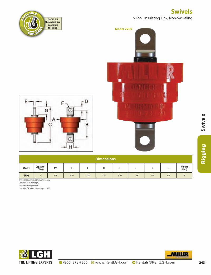
Rigging
Swiv
els
243(800) 878-7305 www.RentLGH.com [email protected]
Model Capacity* (Tons) A** B C D E F G H Weight
(Lbs.)
2VD2 5 7.38 10.50 13.00 1.25 0.88 1.28 2.75 2.50 19
Dimensions
Green shading reflects rental inventory. Dimensions in inches (in.) *5:1 Mech Design Factor **Link profile varies depending on WLL.
Swivels 5 Ton | Insulating Link, Non-Swiveling
Model 2VD2
Items onthis page are
availablefor rent.
AVA
ILABLE
FOR RENT

Rigging
Wire Rope Clips
244 (800) 878-7305 www.RentLGH.com [email protected]
Wire Rope Clips G-450 & SS-450 Model
• Ea ch base has a Product Identification Code (PIC) for material traceability, the name CROSBY or “CG”, and a size forged into it.
• Sizes 1/8” through 21/2” have forged bases.• Entire Clip — Galvanized to resist corrosive and rusting action.• Only Genuine Crosby Clips have a Red U-BOLT for instant
recognition.• All Clips are individually bagged or tagged with proper application
instructions and warning information.• Clip sizes up through 11/2” have rolled threads.
The SS-450 “316” Stainless Steel Wire Rope Clips• Each base has a Product Identification Code (PIC) for
material traceability, the name CROSBY or “CG” and a size forged into it.
• Available in sizes 1/8 through 5/8”.• Entire clip is made from 316 Stainless Steel to resist
corrosive and rusting action.• All components are Electro – Polished.• All Clips are individually bagged or tagged with proper
application instructions and warning information.
Rope Size (in.)
G-450 Model Galv.
Std. Package
Qty.Weight Per
100 (lbs.)
Dimensions (in)
A B C D E F G H
* 1/8 1010015 100 6 .22 .72 .44 .47 .41 .38 .81 .94* 3/16 1010033 100 10 .25 .97 .56 .59 .50 .44 .94 1.16
1/4 1010051 100 19 .31 1.03 .50 .75 .66 .56 1.19 1.44
5/16 1010079 100 28 .38 1.38 .75 .88 .72 .69 1.31 1.69
3/8 1010097 100 48 .44 1.50 .75 1.00 .91 .75 1.63 1.94
7/16 1010113 50 78 .50 1.88 1.00 1.19 1.03 .88 1.81 2.28
1/2 1010131 50 80 .50 1.88 1.00 1.19 1.13 .88 1.91 2.28
9/16 1010159 50 109 .56 2.25 1.25 1.31 1.22 .94 2.06 2.50
5/8 1010177 50 110 .56 2.38 1.25 1.31 1.34 .94 2.06 2.50
3/4 1010195 25 142 .62 2.75 1.44 1.50 1.41 1.06 2.25 2.84
7/8 1010211 25 212 .75 3.12 1.62 1.75 1.59 1.25 2.44 3.16
1 1010239 10 252 .75 3.50 1.81 1.88 1.78 1.25 2.63 3.47
1 1/8 1010257 10 283 .75 3.88 2.00 2.00 1.91 1.25 2.81 3.59
1 1/4 1010275 10 438 .88 4.25 2.13 2.31 2.19 1.44 3.13 4.13
1 3/8 1010293 10 442 .88 4.63 2.31 2.38 2.31 1.44 3.13 4.19
1 1/2 1010319 10 544 .88 4.94 2.38 2.59 2.44 1.44 3.41 4.44
1 5/8 1010337 Bulk 704 1.00 5.31 2.62 2.75 2.66 1.63 3.63 4.75
1 3/4 1010355 Bulk 934 1.13 5.75 2.75 3.06 2.94 1.81 3.81 5.28
2 1010373 Bulk 1,300 1.25 6.44 3.00 3.38 3.28 2.00 4.44 5.88
2 1/4 1010391 Bulk 1,600 1.25 7.13 3.19 3.88 3.19 2.00 4.50 6.38
2 1/2 1010417 Bulk 1,900 1.25 7.69 3.44 4.13 3.69 2.00 4.05 6.63† 2 3/4 1010435 Bulk 2,300 1.25 8.31 3.56 4.38 4.88 2.00 5.00 6.88
3 1010453 Bulk 3,100 1.50 9.19 3.88 4.75 4.69 2.38 5.88 7.63† 3 1/2 1010426 Bulk 4,000 1.50 10.75 4.50 5.50 6.00 2.38 6.19 8.38
Specifications
Rope Size
SS-450 Stock
No.
Weight Per 100
(lbs.)
Dimensions (in.)
A B C D E F G H
1/8 1011250 6 .22 .72 .44 .47 .41 .38 .81 .943/16 1011261 10 .25 .97 .56 .59 .50 .44 .94 1.16
1/4 1011272 20 .31 1.03 .50 .75 .66 .56 1.19 1.44
3/8 1011283 47 .44 1.50 .75 1.00 .91 .75 1.63 1.94
1/2 1011305 77 .50 1.88 1.00 1.19 1.13 .88 1.91 2.28
5/8 1011327 106 .56 2.38 1.25 1.31 1.34 .94 2.06 2.50
Specifications
This page containsThis page contains
ITEMS ONLYITEMS ONLYSALESALE
G-450
SS-450

Rigging
Turn
buck
les
245(800) 878-7305 www.RentLGH.com [email protected]
Thread Diameter & Take Up
(in.)Model
NumberWorking
Load Limit (lbs.)
Weight Each (lbs.)
Dimensions (in.)
A J (open)
K (closed)
M (open)
N (closed) R S X
(closed) BB
† 1/4 x 4 1031252 500 .29 .25 11.94 7.94 12.38 8.38 .81 .34 1.76 4.07† 5/16 x 4 1/12 1031270 800 .48 .31 13.92 9.42 14.48 9.98 .95 .44 2.20 4.58
† 3/8 x 6 1031298 1,200 .75 .38 17.56 11.56 18.24 12.24 1.13 .53 2.48 6.10
1/2 x 6 1031314 2,200 1.72 .50 19.94 13.94 20.82 14.82 1.41 .71 3.56 6.03
1/2 x 12 1031350 2,200 2.63 .50 32.23 20.23 33.11 21.11 1.41 .71 3.54 12.36
5/8 x 6 1031378 3,500 2.75 .63 21.72 15.72 22.72 16.72 1.80 .88 4.35 6.03
5/8 x 12 1031412 3,500 4.12 .63 34.06 22.06 35.06 23.06 1.80 .88 4.34 12.39
3/4 x 6 1031430 5,200 4.22 .75 23.24 17.24 24.50 18.50 2.09 1.00 5.12 6.13
3/4 x 12 1031476 5,200 6.12 .75 35.64 23.64 36.90 24.90 2.09 1.00 5.09 12.59
3/4 x 18 1031494 5,200 7.83 .75 47.64 29.64 48.90 30.90 2.09 1.00 5.12 18.53
7/8 x 12 1031519 7,200 8.83 .88 36.70 24.70 38.20 26.20 2.38 1.25 5.79 12.16
7/8 x 18 1031537 7,200 11.50 .88 49.17 31.17 50.67 32.67 2.38 1.25 5.79 18.63
1 x 6 1031555 10,000 9.62 1.00 26.24 20.24 28.00 22.00 3.00 1.43 6.50 6.18
1 x 12 1031573 10,000 13.00 1.00 38.24 26.24 40.00 28.00 3.00 1.43 6.50 12.18
1 x 18 1031591 10,000 16.30 1.00 50.24 32.24 52.00 34.00 3.00 1.43 6.50 18.18
1 x 24 1031617 10,000 20.20 1.00 62.84 38.84 64.60 40.60 3.00 1.43 6.47 24.84
1 1/4 x 12 1031635 15,200 19.90 1.25 42.14 30.14 44.38 32.38 3.59 1.82 8.49 12.06
1 1/4 x 18 1031653 15,200 23.80 1.25 54.14 36.14 56.38 38.38 3.59 1.82 8.49 18.06
1 1/4 x 24 1031671 15,200 27.80 1.25 66.70 42.70 68.94 44.94 3.59 1.82 8.49 24.62
1 1/2 x 12 1031699 21,400 28.70 1.50 44.24 32.24 46.74 34.74 4.09 2.12 9.46 12.32
1 1/2 x 18 1031715 21,400 34.10 1.50 56.24 38.24 58.74 40.74 4.09 2.12 9.46 18.32
1 1/2 x 24 1031733 21,400 39.60 1.50 68.86 44.86 71.36 47.36 4.09 2.12 9.46 24.94
1 3/4 x 18 1031779 28,000 50.70 1.75 57.38 39.38 60.38 42.38 4.65 2.38 9.97 18.37
1 3/4 x 24 1031797 28,000 58.20 1.75 69.38 45.38 72.38 48.38 4.65 2.38 9.97 24.37
2 x 24 1031819 37,000 83.50 2.00 75.68 51.68 79.18 55.18 5.81 2.69 13.03 24.48
2 1/2 x 24 1031831 60,000 149.00 2.50 79.18 55.18 83.18 59.18 6.49 3.12 13.76 24.60
2 3/4 x 24 1031859 75,000 174.00 2.75 81.34 57.34 85.84 61.84 7.00 3.25 15.09 24.65
Specifications
* Proof load is 2.5 times the working load limit. Ultimate load is 5 times the working load limit.+ Mechanical GalvanizedGreen shading reflects rental inventory.
Meets the performance requirements of Federal Specifications FF-T-791b, Type 1, Form 1 – Class 4, and ASTM F-1145, except for those provisions required of the contractor.
• End fittings are Quenched and Tempered, bodies heat treated by normalizing.• Hot dip galvanized steel.• Turnbuckle eyes are forged elongated, by design, to maximize easy attachment in system and
minimize stress in the eye. For turnbuckles sizes 1/4” through 21/2”, a shackle one size smaller can be reeved through the eye.
Turnbuckles 500 – 75,000 Lbs. | Eye & EyeItems on
this page areavailablefor rent.
AVA
ILABLE
FOR RENT

Rigging
Turnbuckles
246 (800) 878-7305 www.RentLGH.com [email protected]
Turnbuckles 500 – 75,000 Lbs. | Jaw & Eye
• End fittings are Quenched and Tempered, bodies heat treated by normalizing.• Hot dip galvanized steel.• Turnbuckle eyes are forged elongated, by design, to maximize easy attachment in system and
minimize stress in the eye. For turnbuckles sizes 1/4” through 21/2”, a shackle one size smaller can be reeved through the eye.
• Forged jaw ends are fitted with bolts and nuts for 1/4” through 5/8” and pins and cotters on 3/4” through 23/4” sizes
Meets the performance requirements of Federal Specifications FF-T-791b, Type 1, Form 1 – Class 4, and ASTM F-1145, except for those provisions required of the contractor.
Thread Diameter & Take Up
(in.)Model
NumberWorking
Load Limit (lbs.)
Weight Each (lbs.)
Dimensions (in.)
A B E (closed) G J
(open)K
(closed)M
(open)N
(closed) R S X (closed) BB
† 1/4 x 4 1031877 500 .33 .25 .45 1.66 .64 11.57 7.57 12.28 8.28 .81 .34 1.76 4.07† 5/16 x 4 1/12 1031895 800 .52 .31 .50 2.02 .87 13.50 9.00 14.30 9.80 .95 .44 2.20 4.58
† 3/8 x 6 1031911 1,200 .80 .38 .53 2.11 .85 16.91 10.91 17.87 11.87 1.13 .53 2.48 6.10
1/2 x 6 1031939 2,200 1.77 .50 .64 3.22 1.07 19.30 13.30 20.48 14.48 1.41 .71 3.56 6.03
1/2 x 9 1031957 2,200 2.25 .50 .64 3.20 1.07 25.59 16.59 26.77 17.77 1.41 .71 3.54 9.36
1/2 x 12 1031975 2,200 2.67 .50 .64 3.20 1.07 31.59 19.59 32.77 20.77 1.41 .71 3.54 12.36
5/8 x 6 1031993 3,500 2.98 .63 .79 3.90 1.32 20.73 14.73 22.27 16.27 1.80 .88 4.35 6.03
5/8 x 9 1032019 3,500 3.72 .63 .79 3.89 1.32 27.07 18.07 28.61 19.61 1.80 .88 4.34 9.39
5/8 x 12 1032037 3,500 4.35 .63 .79 3.89 1.32 33.07 21.07 34.61 22.61 1.80 .88 4.34 12.39
3/4 x 6 1032055 5,200 4.51 .75 .97 4.71 1.52 22.17 16.17 24.09 18.09 2.09 1.00 5.12 6.13
3/4 x 9 1032073 5,200 5.56 .75 .97 4.68 1.52 28.57 19.57 30.49 21.49 2.09 1.00 5.09 9.59
3/4 x 12 1032091 5,200 6.42 .75 .97 4.68 1.52 34.57 22.57 36.49 24.49 2.09 1.00 5.09 12.59
3/4 x 18 1032117 5,200 8.14 .75 .97 4.71 1.52 46.57 28.57 48.49 30.49 2.09 1.00 5.12 18.53
7/8 x 12 1032135 7,200 9.10 .88 1.16 5.50 1.77 35.68 23.68 37.91 25.91 2.38 1.25 5.79 12.16
7/8 x 18 1032153 7,200 11.60 .88 1.16 5.50 1.77 48.15 30.15 50.38 32.38 2.38 1.25 5.79 18.63
1 x 6 1032171 10,000 10.00 1.00 1.34 6.09 2.05 25.03 19.03 27.59 21.59 3.00 1.43 6.50 6.18
1 x 12 1032199 10,000 13.40 1.00 1.34 6.09 2.05 37.03 25.03 39.59 27.59 3.00 1.43 6.50 12.18
1 x 18 1032215 10,000 16.70 1.00 1.34 6.09 2.05 49.03 31.03 51.59 33.59 3.00 1.43 6.50 18.18
1 x 24 1032233 10,000 20.60 1.00 1.34 6.06 2.05 61.63 37.63 64.19 40.19 3.00 1.43 6.47 24.84
1 1/4 x 12 1032251 15,200 20.90 1.25 1.84 8.09 2.82 40.76 28.76 43.98 31.98 3.59 1.82 8.49 12.06
1 1/4 x 18 1032279 15,200 24.80 1.25 1.84 8.09 2.82 52.76 34.76 55.98 37.98 3.59 1.82 8.49 18.06
1 1/4 x 24 1032297 15,200 28.80 1.25 1.84 8.09 2.82 65.32 41.32 68.54 44.54 3.59 1.82 8.49 24.62
1 1/2 x 12 1032313 21,400 30.60 1.50 2.06 8.93 2.81 42.50 30.50 46.21 34.21 4.09 2.12 9.46 12.32
1 1/2 x 18 1032331 21,400 36.00 1.50 2.06 8.93 2.81 54.50 36.50 58.21 40.21 4.09 2.12 9.46 18.32
1 1/2 x 24 1032359 21,400 41.50 1.50 2.06 8.93 2.81 67.12 43.12 70.83 46.83 4.09 2.12 9.46 24.94
1 3/4 x 18 1032395 28,000 52.10 1.75 2.60 9.39 3.35 55.37 37.37 59.77 41.77 4.65 2.38 9.97 18.37
1 3/4 x 24 1032411 28,000 59.70 1.75 2.60 9.36 3.35 67.37 43.37 71.77 47.77 4.65 2.38 9.97 24.37
2 x 24 1032439 37,000 89.90 2.00 2.62 11.80 3.74 72.66 48.66 77.95 53.95 5.81 2.69 13.03 24.48
2 1/2 x 24 1032457 60,000 158.00 2.50 3.06 13.26 4.44 76.08 52.08 82.68 58.68 6.49 3.12 13.76 24.60
2 3/4 x 24 1032475 75,000 187.00 2.75 3.69 14.92 4.19 78.05 54.05 85.67 61.67 7.00 3.25 15.09 24.65
Specifications
* Proof load is 2.5 times the working load limit. Ultimate load is 5 times the working load limit.+ Mechanical GalvanizedGreen shading reflects rental inventory.
Items onthis page are
availablefor rent.
AVA
ILABLE
FOR RENT

Rigging
Turn
buck
les
247(800) 878-7305 www.RentLGH.com [email protected]
Thread iameter & Take Up
(in.)Model
NumberWorking
Load Limit (lbs.)
Weight Each (lbs.)
Dimensions (in.)
A B E (closed) G J
(open)K
(closed)M
(open)N
(closed) BB† 1/4 x 4 1032493 500 .37 .25 .45 1.66 .64 11.19 7.19 12.18 8.18 4.07
† 5/16 x 4 1/12 1032518 800 .56 .31 .50 2.02 .87 13.07 8.57 14.12 9.62 4.58† 3/8 x 6 1032536 1,200 .85 .38 .53 2.11 .85 16.25 10.25 17.50 11.50 6.101/2 x 6 1032554 2,200 1.82 .50 .64 3.22 1.07 18.65 12.65 20.14 14.14 6.031/2 x 9 1032572 2,200 2.29 .50 .64 3.20 1.07 24.94 15.94 26.43 17.43 9.36
1/2 x 12 1032590 2,200 2.71 .50 .64 3.20 1.07 30.94 18.94 32.43 20.43 12.365/8 x 6 1032616 3,500 3.21 .63 .79 3.90 1.32 19.74 13.74 21.82 15.82 6.035/8 x 9 1032634 3,500 3.95 .63 .79 3.89 1.32 26.08 17.08 28.16 19.16 9.39
5/8 x 12 1032652 3,500 4.58 .63 .79 3.89 1.32 32.08 20.08 34.16 22.16 12.393/4 x 6 1032670 5,200 4.80 .75 .97 4.71 1.52 21.09 15.09 23.68 17.68 6.133/4 x 9 1032698 5,200 5.85 .75 .97 4.68 1.52 27.49 18.49 30.08 21.08 9.59
3/4 x 12 1032714 5,200 6.72 .75 .97 4.68 1.52 33.49 21.49 36.08 24.08 12.593/4 x 18 1032732 5,200 8.45 .75 .97 4.71 1.52 45.49 27.49 48.08 30.08 18.537/8 x 12 1032750 7,200 9.37 .88 1.16 5.50 1.77 34.65 22.65 37.62 25.62 12.167/8 x 18 1032778 7,200 11.80 .88 1.16 5.50 1.77 47.12 29.12 50.09 32.09 18.63
1 x 6 1032796 10,000 10.40 1.00 1.34 6.09 2.05 23.82 17.82 27.18 21.18 6.181 x 12 1032812 10,000 13.80 1.00 1.34 6.09 2.05 35.82 23.82 39.18 27.18 12.181 x 18 1032830 10,000 17.10 1.00 1.34 6.09 2.05 47.82 29.82 51.18 33.18 18.181 x 24 1032858 10,000 21.00 1.00 1.34 6.06 2.05 60.42 36.42 63.78 39.78 24.84
1 1/4 x 12 1032876 15,200 21.90 1.25 1.84 8.09 2.82 39.37 27.37 43.58 31.58 12.061 1/4 x 18 1032894 15,200 25.90 1.25 1.84 8.09 2.82 51.37 33.37 55.58 37.58 18.061 1/4 x 24 1032910 15,200 29.80 1.25 1.84 8.09 2.82 63.93 39.93 68.14 44.14 24.621 1/2 x 12 1032938 21,400 32.60 1.50 2.06 8.93 2.81 40.76 28.76 45.68 33.68 12.321 1/2 x 18 1032956 21,400 38.00 1.50 2.06 8.93 2.81 52.76 34.76 57.68 39.68 18.321 1/2 x 24 1032974 21,400 43.50 1.50 2.06 8.93 2.81 65.38 41.38 70.30 46.30 24.941 3/4 x 18 1033018 28,000 53.50 1.75 2.60 9.36 3.35 53.35 35.35 59.16 41.16 18.371 3/4 x 24 1033036 28,000 61.10 1.75 2.60 9.36 3.35 65.35 41.35 71.16 47.16 24.37
2 x 24 1033054 37,000 96.30 2.00 2.62 11.80 3.74 69.64 45.64 76.72 52.72 24.482 1/2 x 24 1033072 60,000 167.00 2.50 3.06 13.26 4.44 72.97 48.97 82.18 58.18 24.602 3/4 x 24 1033090 75,000 199.00 2.75 3.69 14.92 4.19 74.75 50.75 85.50 61.50 24.65
Specifications
*Proof load is 2.5 times the working load limit. Ultimate load is 5 times the working load limit.+ Mechanical GalvanizedGreen shading reflects rental inventory.
Meets the performance requirements of Federal Specifications FF-T-791b, Type 1, Form 1 – Class 4, and ASTM F-1145, except for those provisions required of the contractor.
Turnbuckles 500 – 75,000 Lbs. | Jaw & JawItems on
this page areavailablefor rent.
AVA
ILABLE
FOR RENT • End fittings are Quenched and Tempered, bodies heat treated by normalizing.
• Hot dip galvanized steel.• Turnbuckle eyes are forged elongated, by design, to maximize easy attachment in system and
minimize stress in the eye. For turnbuckles sizes 1/4” through 21/2”, a shackle one size smaller can be reeved through the eye.
• Forged jaw ends are fitted with bolts and nuts for 1/4” through 5/8” and pins and cotters on 3/4” through 23/4” sizes

Rigging
Modular Spreader Beam
s
248 (800) 878-7305 www.RentLGH.com [email protected]
Modular Spreader Beams Modulift® Spreader Beams
Available to Rent from Lifting Gear Hire
The Modulift® Spreader Beam System, available to rent from LGH is a range of beams that offer a modular span capability with a wide range of loading capacities.
Unlike fixed length spreader beams, the flexibility of the Modulift® Spreader Beam System means that even the most awkward loads can be accommodated. Using a range of different components together means an almost infinite number of configurations are possible to suit virtually any lifting scenario.
Designed for easy one-man assembly, the Modulift® Spreader Beam System is both portable and lightweight. Most of the beams and end units within the system can be easily manually handled on site without the need for lifting equipment, reducing both the time needed for set-up and expensive crane time. The majority of the Modulift® Spreader Beam System components are light enough to be transported in a small van or pick-up, helping to cut transportation costs.
Versatility
The Modulift® Spreader Beam System offers almost limitless versatility with spreaders ranging from 3 feet to 100 feet in 1 to 2 foot increments depending on which size spreader is used. Models include carrying capacities from 24T up to 1200T (MOD24 - MOD1000/1200). Accessories for the system are available including corner units for square and rectangular frames.
End Unit Sub-Assy
Lightweight portable design
Quick and easy assemble/dismantle
In most cases – a one man operation
Easily transported
Flexible configurations to meet a variety of demands
Uses conventional shackles and accessories
Reduced labor costs
Reduced downtime
Reduced crane time and associated rental costs
Reduced transportation costs
No need to invest, store and maintain large numbers of fixed spreaders – one system will do it all.
No specialist accessories required.
Benefits of Renting a Modulift Spreader Beam from LGH
Strut
Items onthis page are
availablefor rent.
AVA
ILABLE
FOR RENT

Rigging
Mod
ular
Spr
eade
r Bea
ms
249(800) 878-7305 www.RentLGH.com [email protected]
CMOD 50 - FRAME SPECIFICATIONRated at a maximum of 60 tons WLL please see table 2 for WLL's at specific spansBase to Sling Angle, α, no less than 45 degreesCorner Units are rated at 15 tons each (60t combined capacity)Bolt tightening torque: 110 lb•ft. Spanner size required: 1.18 inchesRecommended additional equipment: Torque Wrench, Podger Spanner and Ring Spanner
Part Description Weight
P1 Corner Unit 345 Lbs.
P2 12 Ft. Strut 285 Lbs.
P3 6 Ft. Strut 168 Lbs.
P4 3 Ft. Strut 109 Lbs.
P5 2 Ft. Strut 90 Lbs.
P6 1 Ft. Strut 70 Lbs.
P7 35T Shackle 44 Lbs.
P8 25T Shackle 31 Lbs.
P9 Bolts, Nuts And Washers
P10 50T Drop Link 24 Lbs.
Table 1: Component List
Modular Spreader Frames 12 – 60 Ton | CMOD 50 | Corner UnitItems on
this page areavailablefor rent.
AVA
ILABLE
FOR RENT
Assembled Frame
P9
P7
P2 - P6P1
Span
α = ‘Base to Sling’ Angle (BSA)
Fig. 1. Typical Spreader Assembly
α
P8
Corner Unit
Strut
• Max number of struts allowed in assembly: 5 per side• Assemble longer struts in the center of the configuration• Sling angle is crucial to safe use of frame

Rigging
Modular Spreader Beam
s
250 (800) 878-7305 www.RentLGH.com [email protected]
Modular Spreader Beams 12 – 60 Ton | CMOD 50 | Corner Modular Beam
36 32
34 38 31
31 45 36 30
28 54 44 34 29
25 54 53 42 33 27
22 60 53 51 40 32 26
19 60 60 51 47 38 30 25
16 60 60 56 47 45 36 29 25
13 60 60 60 52 45 43 34 28 24
10 60 60 60 60 50 45 42 34 27 23
7 60 60 60 60 60 50 45 41 33 26 23
4 60 60 60 60 60 60 50 45 41 31 26 22
Span (ft) 4 7 10 13 16 19 22 25 28 31 34 36
CMOD 50: WWL / tonnes @ 60° BSA
Load charts only to be used in conjunction with CMOD 50 User InstructionsFirst pick the span required for your frame (e.g. 10' x 28') and the Sling Angle (we recommend 60° BSA where possible), then check the WLL via the appropriate table. Read the table by locating the lower span on the y axis of the chart and the larger on the x. The cell which you are referred to will indicate the WLL for your chosen span. If your exact span is not noted in the table, then please round up or down to the values that will give you the lowest WLL (to ensure no overloads are applied). Please contact Lifting Gear Hire for confirmation on your WLL if required. WLL given in tons.
Assembled Frame:
36 18
34 22 18
31 25 21 17
28 31 24 19 16
25 31 30 23 18 15
22 31 30 29 22 18 14
19 40 31 29 27 22 17 14
16 40 40 29 27 25 21 16 13
13 50 40 36 27 25 24 19 15 13
10 50 50 40 36 25 25 23 19 15 12
7 50 50 50 40 36 25 25 22 18 14 12
4 50 50 50 50 40 36 25 25 22 18 14 12
Span (ft) 4 7 10 13 16 19 22 25 28 31 34 36
CMOD 50: WWL / tonnes @ \ 45° BSA
Items onthis page are
availablefor rent.
AVA
ILABLE
FOR RENT

Rigging
Mod
ular
Spr
eade
r Bea
ms
251(800) 878-7305 www.RentLGH.com [email protected]
Part Ref: Description Item Weight lbs.
P1 End Unit (1 1/2 ft.) 36
P2 Drop Link 11
P3 6 ft. Strut 80
P4 4 ft. Strut 56
P5 2 ft. Strut 37
P6 1 ft. Strut 26
P7 17t Shackle 18
P8 12t Shackle 11
P9 M20x50 Grade 8.8 HT Bolts, Nuts & Wachers
Table 1: Component List
Green shading reflects rental inventory.•Beam weights calculated without top rigging.
P1 P2P3–P6
Span
P7
9P8P
α
Typical Spreader Assembly
• Rated at 24t WLL at 11 ft. span. See Load Table for WLL at spans greater than 11 ft.
• Base sling angle, α, 45 degrees or greater.• End Units & Drop Links are rated at 12t
(24t combined capacity).• Bolt tightening torque: 110 pound-foot.
• Max number of struts allowed in spreader assembly: 5• Assemble longer struts in the center of the spreader
configuration• Sling angle is crucial to safe use of spreader
Modular Spreader Beams 2.6 – 24 Ton | Mod 24
NOTE: Top Slings shall be properly load-rated based on the specified angle used. LGH top sling inventory is based on Rental Center location availability.
Items onthis page are
availablefor rent.
AVA
ILABLE
FOR RENT
Span (ft)
Base to Sling Angle (BSA) α
Recommended ConfigurationEU - End Unit (1.5 ft)
Beam Weight
(lbs.)
45° 60° 70°
WLLmetric
tons (tonnes)
Min. top
sling length (ft in)
WLLmetric
tons (tonnes)
Min. top
sling length (ft in)
WLLmetric
tons (tonnes)
Min. top
sling length (ft in)
3 24 1’7’’ 24 2’6’’ 24 3’11’’ EU EU — 151
4 24 2’4’’ 24 3’6’’ 5’4’’ 37’6’’ EU 1 EU — 177
5 24 3’0’’ 24 4’6’’ 24 6’10’’ EU 2 EU — 188
6 24 3’8’’ 24 5’6’’ 24 8’4’’ EU 2 1 EU — 214
7 24 4’6’’ 24 6’6’’ 24 9’8’’ EU 4 EU — 207
8 24 5’2’’ 24 7’6’’ 24 11’2’’ EU 4 1 EU — 233
9 24 5’11’’ 24 8’6’’ 24 12’8’’ EU 6 EU — 231
10 24 6’7’’ 24 9’6’’ 24 14’1’’ EU 6 1 EU — 257
11 22 7’4’’ 24 10’6’’ 24 15’7’’ EU 6 2 EU — 268
12 19 8’0’’ 24 11’6’’ 24 17’0’’ EU 2 6 1 EU — 294
13 16 8’8’’ 24 12’6’’ 24 18’6’’ EU 4 6 EU — 287
14 13 9’5’’ 24 13’6’’ 24 20’0’’ EU 4 6 1 EU — 313
15 11 10’1’’ 20 14’6’’ 24 21’5’’ EU 6 6 EU — 311
16 10 10’10’’ 17 15’6’’ 24 22’11’’ EU 6 6 1 EU — 337
17 8.6 11’6’’ 15 16’6’’ 24 24’5’’ EU 6 6 2 EU — 348
18 7.4 12’2’’ 13 17’6’’ 20 25’10’’ EU 1 6 6 2 EU — 374
19 6.5 12’11’’ 11 18’6’’ 18 27’4’’ EU 6 6 4 EU — 367
20 5.6 13’7’’ 9.9 19’6’’ 15 28’8’’ EU 1 6 6 4 EU — 393
21 5 14’5’’ 8.8 20’6’’ 14 30’2’’ EU 6 6 6 EU — 391
22 4.4 15’1’’ 7.7 21’6’’ 12 31’8’’ EU 6 6 6 1 EU — 417
23 3.8 15’10’’ 6.8 22’6’’ 10 33’1’’ EU 6 6 6 2 EU — 428
24 3.4 16’6’’ 6 23’6’’ 9.6 34’7’’ EU 1 6 6 6 2 EU 454
25 3 17’2’’ 5.3 24’6’’ 8.6 36’0’’ EU 6 6 6 4 EU — 447
26 2.6 17’11’’ 4.7 25’6’’ 7.6 37’6’’ EU 1 6 6 6 4 EU 473
Table 2: Load V. Span
Green shading reflects rental inventory.•Beam weights calculated without top rigging.

Rigging
Modular Spreader Beam
s
252 (800) 878-7305 www.RentLGH.com [email protected]
Modular Spreader Beams 4.1 – 50 Ton | Mod 50
• Rated at 50t WLL at 20 ft. span. See Load Table for WLL at spans greater than 20 ft.
• Base sling angle, α, 45 degrees or greater.• End Units & Drop Links are rated at 25t
(50t combined capacity).• Bolt tightening torque: 110 pound-foot.
• Max number of struts allowed in spreader assembly: 5• Assemble longer struts in the center of the spreader
configuration• Sling angle is crucial to safe use of spreader
P1 P2P3–P7
Span
P8
01P9P
α
Typical Spreader Assembly
Part Ref: Description Item Weight lbs.
P1 End Unit (1 1/2 ft.) 84
P2 Drop Link 24
P3 12 ft. Strut 285
P4 6 ft. Strut 168
P5 3 ft. Strut 109
P6 2 ft. Strut 90
P7 1 ft. Strut 70
P8 35t Shackle 44
P9 35t Shackle 44
P10 M20x65 Grade 8.8 HT Bolts, Nuts & Washers
Table 1: Component List
Green shading reflects rental inventory.•Beam weights calculated without top rigging.
NOTE: Top Slings shall be properly load-rated based on the specified angle used. LGH top sling inventory is based on Rental Center location availability.
Items onthis page are
availablefor rent.
AVA
ILABLE
FOR RENT
Base to Sling Angle (BSA) α
Recommended ConfigurationEU - End Unit (1.5 ft)
Beam Weight
(lbs.)Span (ft.)
45° 60° 70°
WLL metric
tons (tonnes)
Min. top
sling length (ft in)
WLL metric
tons (tonnes)
Min. top
sling length (ft in)
WLL metric
tons (tonnes)
Min. top
sling length (ft in)
3 50 1’5’’ 50 2’4’’ 50 3’8’’ EU EU — 384
4 50 2’1’’ 50 3’4’’ 50 5’2’’ EU 1 EU — 454
5 50 2’10’’ 50 4’4’’ 50 6’7’’ EU 2 EU 474
6 50 3’7’’ 50 5’4’’ 50 8’1’’ EU 3 EU — 493
7 50 4’4’’ 50 6’4’’ 50 9’6’’ EU 3 1 EU — 563
8 50 5’0’’ 50 7’4’’ 50 11’0’’ EU 3 2 EU — 583
9 50 5’8’’ 50 8’4’’ 50 12’6’’ EU 6 EU — 552
10 50 6’5’’ 50 9’4’’ 50 13’11’’ EU 6 1 EU — 622
11 50 7’1’’ 50 10’4’’ 50 15’5’’ EU 6 2 EU — 642
12 50 7’10’’ 50 11’4’’ 50 16’11’’ EU 6 3 EU — 661
13 50 8’6’’ 50 12’4’’ 50 18’4’’ EU 3 6 1 EU — 731
14 50 9’2’’ 50 13’4’’ 50 19’10’’ EU 3 6 2 EU — 751
15 50 9’11’’ 50 14’4’’ 50 21’2’’ EU 12 EU — 669
16 48 10’7’’ 50 15’4’’ 50 22’8’’ EU 12 1 EU — 739
17 44 11’4’’ 50 16’4’’ 50 24’2’’ EU 12 2 EU — 759
18 41 12’0’’ 50 17’4’’ 50 25’7’’ EU 12 3 EU — 778
19 37 12’8’’ 50 18’4’’ 50 27’1’’ EU 3 12 1 EU — 848
20 33 13’6’’ 50 19’4’’ 50 28’6’’ EU 3 12 2 EU — 868
21 30 14’2’’ 50 20’4’’ 50 30’0’’ EU 6 12 EU — 837
22 27 14’11’’ 47 21’4’’ 50 31’6’’ EU 6 12 1 EU — 907
23 24 15’7’’ 42 22’4’’ 50 32’11’’ EU 6 12 2 EU — 927
24 22 16’4’’ 38 23’4’’ 50 34’5’’ EU 6 12 3 EU — 946
25 19 17’0’’ 34 24’4’’ 50 35’11’’ EU 3 6 12 1 EU 1016
26 17 17’8’’ 30 25’4’’ 49 37’4’’ EU 3 6 12 2 EU 1036
27 16 18’5’’ 28 26’4’’ 45 38’10’’ EU 12 12 EU — 954
28 14 19’1’’ 25 27’4’’ 41 40’2’’ EU 12 12 1 EU — 1024
29 13 19’10’’ 23 28’4’’ 37 41’8’’ EU 12 12 2 EU — 1044
30 12 20’6’’ 21 29’4’’ 34 43’2’’ EU 12 12 3 EU — 1063
31 11 21’2’’ 19 30’4’’ 31 44’7’’ EU 3 12 12 1 EU 1133
32 10 21’11’’ 17 31’4’’ 28 46’1’’ EU 3 12 12 2 EU 1153
33 9.3 22’7’’ 16 32’4’’ 26 47’7’’ EU 6 12 12 EU — 1122
34 8.4 23’5’’ 14 33’4’’ 24 49’0’’ EU 6 12 12 1 EU 1192
35 7.7 24’1’’ 13 34’4’’ 21 50’6’’ EU 6 12 12 2 EU 1212
36 7 24’10’’ 12 35’4’’ 20 51’11’’ EU 6 12 12 3 EU 1231
37 6.3 25’6’’ 11 36’4’’ 18 53’5’’ EU 6 12 12 3 1 EU 1301
38 5.7 26’2’’ 10 37’4’’ 16 54’11’ EU 6 12 12 3 2 EU 1321
39 5.3 26’11’’ 9.6 38’4’’ 15 56’4’’ EU 12 12 6 6 EU 1290
40 5 27’7’’ 9 39’4’’ 14 57’10’’ EU 12 12 12 1 EU 1309
41 4.5 28’4’’ 8.3 40’4’’ 13 59’2’’ EU 12 12 12 2 EU 1329
42 4.1 29’0’’ 7.5 41’4’’ 12 60’8’’ EU 12 12 12 2 1 EU 1399
Table 2: Load v. Span
Green shading reflects rental inventory.•Beam weights calculated without top rigging
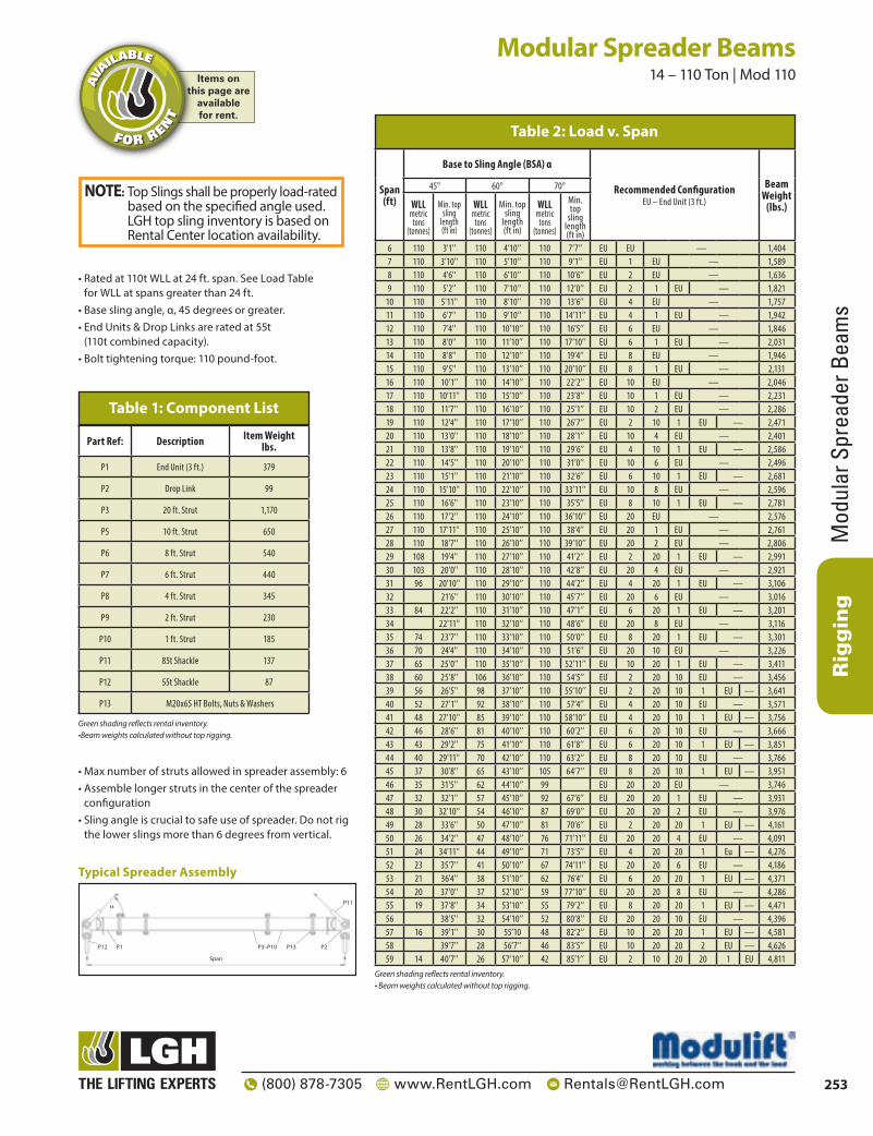
Rigging
Mod
ular
Spr
eade
r Bea
ms
253(800) 878-7305 www.RentLGH.com [email protected]
Modular Spreader Beams 14 – 110 Ton | Mod 110
• Rated at 110t WLL at 24 ft. span. See Load Table for WLL at spans greater than 24 ft.
• Base sling angle, α, 45 degrees or greater.• End Units & Drop Links are rated at 55t
(110t combined capacity).• Bolt tightening torque: 110 pound-foot.
• Max number of struts allowed in spreader assembly: 6• Assemble longer struts in the center of the spreader
configuration• Sling angle is crucial to safe use of spreader. Do not rig
the lower slings more than 6 degrees from vertical.
P1 P2P3–P10
Span
P11
31P21P
α
Typical Spreader Assembly
Span (ft)
Base to Sling Angle (BSA) α
Recommended ConfigurationEU – End Unit (3 ft.)
Beam Weight
(lbs.)
45° 60° 70°
WLL metric
tons (tonnes)
Min. top sling
length (ft in)
WLL metric
tons (tonnes)
Min. top sling
length (ft in)
WLL metric
tons (tonnes)
Min. top
sling length (ft in)
6 110 3'1'' 110 4’10’’ 110 7’7’’ EU EU — 1,4047 110 3'10'' 110 5’10’’ 110 9’1’’ EU 1 EU — 1,5898 110 4'6'' 110 6’10’’ 110 10’6’’ EU 2 EU — 1,6369 110 5'2'' 110 7’10’’ 110 12’0’’ EU 2 1 EU — 1,821
10 110 5'11'' 110 8’10’’ 110 13’6’’ EU 4 EU — 1,75711 110 6'7'' 110 9’10’’ 110 14’11’’ EU 4 1 EU — 1,94212 110 7'4'' 110 10’10’’ 110 16’5’’ EU 6 EU — 1,84613 110 8'0'' 110 11’10’’ 110 17’10’’ EU 6 1 EU — 2,03114 110 8'8'' 110 12’10’’ 110 19’4’’ EU 8 EU — 1,94615 110 9'5'' 110 13’10’’ 110 20’10’’ EU 8 1 EU — 2,13116 110 10'1'' 110 14’10’’ 110 22’2’’ EU 10 EU — 2,04617 110 10'11'' 110 15’10’’ 110 23’8’’ EU 10 1 EU — 2,23118 110 11'7'' 110 16’10’’ 110 25’1’’ EU 10 2 EU — 2,28619 110 12'4'' 110 17’10’’ 110 26’7’’ EU 2 10 1 EU — 2,47120 110 13'0'' 110 18’10’’ 110 28’1’’ EU 10 4 EU — 2,40121 110 13'8'' 110 19’10’’ 110 29’6’’ EU 4 10 1 EU — 2,58622 110 14'5'' 110 20’10’’ 110 31’0’’ EU 10 6 EU — 2,49623 110 15'1'' 110 21’10’’ 110 32’6’’ EU 6 10 1 EU — 2,68124 110 15'10'' 110 22’10’’ 110 33’11’’ EU 10 8 EU — 2,59625 110 16'6'' 110 23’10’’ 110 35’5’’ EU 8 10 1 EU — 2,78126 110 17'2'' 110 24’10’’ 110 36’10’’ EU 20 EU — 2,57627 110 17'11'' 110 25’10’’ 110 38’4’’ EU 20 1 EU — 2,76128 110 18'7'' 110 26’10’’ 110 39’10’’ EU 20 2 EU — 2,80629 108 19'4'' 110 27’10’’ 110 41’2’’ EU 2 20 1 EU — 2,99130 103 20'0'' 110 28’10’’ 110 42’8’’ EU 20 4 EU — 2,92131 96 20'10'' 110 29’10’’ 110 44’2’’ EU 4 20 1 EU — 3,10632 21'6'' 110 30’10’’ 110 45’7’’ EU 20 6 EU — 3,01633 84 22'2'' 110 31’10’’ 110 47’1’’ EU 6 20 1 EU — 3,20134 22'11'' 110 32’10’’ 110 48’6’’ EU 20 8 EU — 3,11635 74 23'7'' 110 33’10’’ 110 50’0’’ EU 8 20 1 EU — 3,30136 70 24'4'' 110 34’10’’ 110 51’6’’ EU 20 10 EU — 3,22637 65 25'0'' 110 35’10’’ 110 52’11’’ EU 10 20 1 EU — 3,41138 60 25'8'' 106 36’10’’ 110 54’5’’ EU 2 20 10 EU — 3,45639 56 26'5'' 98 37’10’’ 110 55’10’’ EU 2 20 10 1 EU — 3,64140 52 27'1'' 92 38’10’’ 110 57’4’’ EU 4 20 10 EU — 3,57141 48 27'10'' 85 39’10’’ 110 58’10’’ EU 4 20 10 1 EU — 3,75642 46 28'6'' 81 40’10’’ 110 60’2’’ EU 6 20 10 EU — 3,66643 43 29'2'' 75 41’10’’ 110 61’8’’ EU 6 20 10 1 EU — 3,85144 40 29'11'' 70 42’10’’ 110 63’2’’ EU 8 20 10 EU — 3,76645 37 30'8'' 65 43’10’’ 105 64’7’’ EU 8 20 10 1 EU — 3,95146 35 31'5'' 62 44’10’’ 99 EU 20 20 EU — 3,74647 32 32'1'' 57 45’10’’ 92 67’6’’ EU 20 20 1 EU — 3,93148 30 32'10'' 54 46’10’’ 87 69’0’’ EU 20 20 2 EU — 3,97649 28 33'6'' 50 47’10’’ 81 70’6’’ EU 2 20 20 1 EU — 4,16150 26 34'2'' 47 48’10’’ 76 71’11’’ EU 20 20 4 EU — 4,09151 24 34'11'' 44 49’10’’ 71 73’5’’ EU 4 20 20 1 Eu — 4,27652 23 35'7'' 41 50’10’’ 67 74’11’’ EU 20 20 6 EU — 4,18653 21 36'4'' 38 51’10’’ 62 76’4’’ EU 6 20 20 1 EU — 4,37154 20 37'0'' 37 52’10’’ 59 77’10’’ EU 20 20 8 EU — 4,28655 19 37'8'' 34 53’10’’ 55 79’2’’ EU 8 20 20 1 EU — 4,47156 38'5'' 32 54’10’’ 52 80’8’’ EU 20 20 10 EU — 4,39657 16 39'1'' 30 55’10 48 82’2’’ EU 10 20 20 1 EU — 4,58158 39'7'' 28 56’7’’ 46 83’5’’ EU 10 20 20 2 EU — 4,62659 14 40'7'' 26 57’10’’ 42 85’1’’ EU 2 10 20 20 1 EU 4,811
Table 2: Load v. Span
Green shading reflects rental inventory.• Beam weights calculated without top rigging.
NOTE: Top Slings shall be properly load-rated based on the specified angle used. LGH top sling inventory is based on Rental Center location availability.
Items onthis page are
availablefor rent.
AVA
ILABLE
FOR RENT
Part Ref: Description Item Weight lbs.
P1 End Unit (3 ft.) 379
P2 Drop Link 99
P3 20 ft. Strut 1,170
P5 10 ft. Strut 650
P6 8 ft. Strut 540
P7 6 ft. Strut 440
P8 4 ft. Strut 345
P9 2 ft. Strut 230
P10 1 ft. Strut 185
P11 85t Shackle 137
P12 55t Shackle 87
P13 M20x65 HT Bolts, Nuts & Washers
Table 1: Component List
Green shading reflects rental inventory.•Beam weights calculated without top rigging.

Rigging
Modular Spreader Beam
s
254 (800) 878-7305 www.RentLGH.com [email protected]
Modular Spreader Beams 14 – 170 Ton | Mod 110H
Span (ft)
Base to Sling Angle (BSA) α
Recommended ConfigurationEU - End Unit (3 ft)
Beam Weight
(lbs.)
45° 60° 70°
WLL metric
tons (tonnes)
Min. top
sling length (ft in)
WLL metric
tons (tonnes
Min. top
sling length (ft in
WLL metric
tons (tonnes)
Min. top sling
length (ft in
6 167 2’10’’ 170 4’7’’ 170 7’5’’ EU EU — 1,8707 167 3’6’’ 170 5’7’’ 170 8’10’’ EU 1 EU — 2,0538 167 4’2’’ 170 6’7’’ 170 10’4’’ EU 2 EU — 2,1009 167 4’11’’ 170 7’7’’ 170 11’8’’ EU 2 1 EU — 2,285
10 167 5’8’’ 170 8’7’’ 170 13’2’’ EU 4 EU — 2,22111 167 6’5’’ 170 9’7’’ 170 14’8’’ EU 4 1 EU — 2,40612 167 7’1’’ 170 10’7’’ 170 16’1’’ EU 6 EU — 2,31013 167 7’10’’ 170 11’7’’ 170 17’7’’ EU 6 1 EU — 2,49514 167 8’6’’ 170 12’7’’ 170 19’0” EU 8 EU — 2,41015 167 9’2’’ 170 13’7’’ 170 20’6’’ EU 8 1 EU — 2,59516 167 9’11’’ 170 14’7’’ 170 22’0’’ EU 10 EU — 2,51017 167 10’7’’ 170 15’7’’ 170 22’0’’ EU 10 1 EU — 2,69518 167 11’4’’ 170 16’7’’ 170 24’11’’ EU 10 2 EU — 2,75019 167 12’0’’ 170 17’7’’ 170 26’5’’ EU 2 10 1 EU — 2,93520 167 12’8’’ 170 18’7’’ 170 27’10’’ EU 10 4 EU — 2,86521 160 13’5’’ 170 19’7’’ 170 29’4’’ EU 4 10 1 EU — 3,05022 155 14’1’’ 170 20’7’’ 170 30’8’’ EU 10 6 EU — 2,96023 148 14’10’’ 170 21’7’’ 170 32’2’’ EU 6 10 1 EU — 3,14524 142 15’7’’ 170 22’7’’ 170 33’8’’ EU 10 8 EU — 3,06025 135 16’4’’ 170 23’7’’ 170 35’1’’ EU 8 10 1 EU — 3,24526 128 17’0’’ 170 24’7’’ 170 36’7’’ EU 20 EU — 3,04027 121 17’8’’ 170 25’7’’ 170 38’1’’ EU 20 1 EU — 3,22528 115 18’5’’ 170 26’7’’ 170 39’6’’ EU 20 2 EU — 3,27029 108 19’1’’ 170 27’7’’ 170 41’0’’ EU 2 20 1 EU — 3,45530 103 19’10’’ 170 28’7’’ 170 42’5’’ EU 20 4 EU — 3,38531 96 20’6’’ 168 29’7’’ 170 43’11’’ EU 4 20 1 EU — 3,57032 91 21’2’’ 158 30’7’’ 170 45’5’’ EU 20 6 EU — 3,48033 84 21’11’’ 147 31’7’’ 170 46’10’’ EU 6 20 1 EU — 3,66534 80 22’7’ 139 32’7’’ 170 48’4’’ EU 20 8 EU — 3,58035 74 23’4’’ 129 33’7’’ 170 49’8’’ EU 8 20 1 EU — 3,76536 70 24”0” 122 34’7’’ 170 51’2’’ EU 20 10 EU — 3,69037 65 24’8’’ 113 35’7’’ 170 52’8’’ EU 10 20 1 EU — 3,87538 60 25’6’’ 106 36’7’’ 169 54’1’’ EU 2 20 10 EU — 3,92039 56 26’2’’ 98 37’7’’ 156 55’7’’ EU 2 20 10 1 EU — 4,10540 52 26’11’’ 92 38’7’’ 146 57’1’’ EU 4 20 10 EU — 4,03541 48 27’7’’ 85 39’7’’ 136 58’6’’ EU 4 20 10 1 EU — 4,22042 46 26’11’’ 81 40’7’’ 130 57’1’’ EU 6 20 10 EU — 4,13043 43 29’0’’ 75 41’7’’ 121 61’5’’ EU 6 20 10 1 EU — 4,31544 40 29’8’’ 70 42’7’’ 113 62’11’’ EU 8 20 10 EU — 4,23045 37 30’5’’ 65 43’7’’ 105 64’5’’ EU 8 20 10 1 EU — 4,41546 35 31’1’’ 62 44’7’’ 99 65’10’’ EU 20 20 EU — 4,21047 32 31’10’’ 57 45’7’’ 92 67’4’’ EU 20 20 1 EU — 4,39548 30 32’6’’ 54 46’7’’ 87 68’10’’ EU 20 20 2 EU — 4,44049 28 33’2’’ 50 47’7’’ 81 70’2’’ EU 2 20 20 1 EU — 4,62550 26 33’11’’ 47 48’7’’ 76 71’8’’ EU 20 20 4 EU — 4,55551 24 34’7’’ 44 49’7’’ 71 73’1’’ EU 4 20 20 1 EU — 4,74052 23 35’5’’ 41 50’7’’ 67 74’7’’ EU 20 20 6 EU — 4,65053 21 36’1’’ 38 51’7’’ 62 76’1’’ EU 6 20 20 1 EU — 4,83554 20 36’10’’ 37 50’7’’ 59 74’7’’ EU 20 20 8 EU — 4,75055 19 37’6’’ 34 53’7’’ 55 79’0’’ EU 8 20 20 1 EU — 4,93556 17 38’2’’ 32 54’7’’ 52 80’5’’ EU 20 20 10 EU — 4,86057 16 38’11’’ 30 55’7’’ 48 81’11’’ EU 10 20 20 1 EU — 5,04558 15 39’10’’ 28 56’7’’ 46 83’5’’ EU 10 20 20 2 EU — 4,62659 14 40’4’’ 26 57’7’’ 42 84’10’’ EU 2 10 20 20 1 EU 5,275
Table 2: Load v. Span
Green shading reflects rental inventory. | •Beam weights calculated without top rigging*Spans available in 1 foot increments
• Max number of struts allowed in spreader assembly: 6• Assemble longer struts in the center of the spreader
configuration• Sling angle is crucial to safe use of spreader. Do not rig the
lower slings more than 6 degrees from vertical.
• Rated at 170t WLL at 28 ft. span. See Load Table for WLL at spans greater than 28 ft.
• Base sling angle, α, 45 degrees or greater.• End Units & Drop Links are rated at 85t
(170t combined capacity).• Bolt tightening torque: 110 pound-foot.
P1 P2P3–P10
Span
P11
31P21P
α
Typical Spreader Assembly
NOTE: Top Slings shall be properly load-rated based on the specified angle used. LGH top sling inventory is based on Rental Center location availability.
Items onthis page are
availablefor rent.
AVA
ILABLE
FOR RENT
Part Ref: Description Item Weight lbs.
P1 End Unit (3 ft.) 384
P2 Drop Link 171
P3 20 ft. Strut 1,170
P5 10 ft. Strut 650
P6 8 ft. Strut 540
P7 6 ft. Strut 440
P8 4 ft. Strut 345
P9 2 ft. Strut 230
P10 1 ft. Strut 185
P11 120t Shackle 243
P12 85t Shackle 137
P13 M20x65 HT Bolts, Nuts & Washers
Table 1: Component List
Green shading reflects rental inventory.•Beam weights calculated without top rigging.

Rigging
Mod
ular
Spr
eade
r Bea
ms
255(800) 878-7305 www.RentLGH.com [email protected]
Part Ref: Description Weight/Item
lbs.P1 Mod 110 End Unit 379
P2 Mod 110 Drop Link 99
P3 20 ft. Strut 3049
P4 10 ft. Strut 1744
P5 5 ft. Strut 1094
P6 4 ft. Strut 963
P7 3 ft. Strut 832
P8 2 ft. Strut 701
P9 1 ft. Strut 571
P10 Mod 400/110 Cone Adaptor 441
P11 85t Bolt Shackle 137
P12 55t Bolt Shackle 87
P13 MOD: 400 M24 x 90, Grade 8.8, HT Bolts, Nuts & Washers MOD: 110 M20 x 65, Grade 8.8, HT Bolts, Nuts & Washers
Table 1: Component List
Green shading reflects rental inventory.•Beam weights calculated without top rigging.
Modular Spreader Beams 47 – 110 Ton | Mod 400/110
P1 P2P3–P9Span
α P11P10
31P21P
Typical Spreader Assembly
• Rated at 110t WLL at 76 ft. span.• Base sling angle, α, 45 degrees or greater.• End Units & Drop Links are rated at 55t (110t
combined capacity).• Bolt tightening torque: 184 pound-foot
(M24); 110 pound-foot (M20)
• Max number of struts allowed in spreader assembly: 5
• Assemble longer struts in the center of the spreader configuration
• Sling angle is crucial to safe use of spreader. Do not rig the lower slings more than 6 degrees from vertical.
Span (ft)
Base to Sling Angle (BSA) αRecommended Configuration
EU - End Unit (3 ft), CA - Cone Adaptor (2 ft)
To calculate the WLL at intermediate spans utilizing the 1ft strut, round up the span to the next longest span in
Table 2, and use the stated WLL.
Beam Weight
(lbs.)
45° 60° 70°
WLLmetric
tons (tonnes)
Min. top sling
length (ft in)
WLLmetric
tons (tonnes)
Min. top sling
length (ft in)
WLLmetric
tons (tonnes)
Min. top sling
length (ft in)
6 110 3’1’’ 110 4’10’’ 110 7’7’’ EU EU — 1,436
10 110 5’11’ 110 8’10’’ 110 13’6’’ EU CA CA EU — 2,252
12 110 7’4’’ 110 10’10’’ 110 16’5’’ EU CA 2 CA EU — 2,968
14 110 8’8’’ 110 12’10’’ 110 19’4’’ EU CA 4 CA EU — 3,132
16 110 10’1’’ 110 14’10’’ 110 22’2’’ EU CA 5 1 CA EU — 3,931
18 110 11’7’’ 110 16’10’’ 110 25’1’’ EU CA 5 3 CA EU — 4,178
20 110 13’0’’ 110 18’10’’ 110 28’1’’ EU CA 10 CA EU — 3,914
22 110 14’5’’ 110 20’10’’ 110 31’0’’ EU CA 10 2 CA EU — 4,630
24 110 15’10’’ 110 22’10’’ 110 33’11’’ EU CA 10 4 CA EU — 4,794
26 110 17’2’’ 110 24’’10’ 110 36’10’’ EU CA 5 10 1 CA EU — 5,593
28 110 18’7’’ 110 26’10’’ 110 39’10’’ EU CA 5 10 3 CA EU — 5,840
30 110 20’0’’ 110 28’10’’ 110 42’8’’ EU CA 20 CA EU — 5,217
32 110 21’6’’ 110 30’10’’ 110 45’7’’ EU CA 20 2 CA EU — 5,933
34 110 22’11’’ 110 32’10’’ 110 48’6’’ EU CA 20 4 CA EU — 6,097
36 110 24’4’’ 110 34’10’’ 110 51’6’’ EU CA 5 20 1 CA EU — 6,896
38 110 25’8’’ 110 36’10’’ 110 54’5’’ EU CA 5 20 3 CA EU — 7,143
40 110 27’1’’ 110 38’10’’ 110 57’4’’ EU CA 10 20 CA EU — 6,879
42 110 28’6’’ 110 40’10’’ 110 60’2’’ EU CA 10 20 2 CA EU — 7,595
44 110 29’11’’ 110 42’10’’ 110 63’2’’ EU CA 10 20 4 CA EU — 7,759
46 110 31’5’’ 110 44’10’’ 110 66’1’’ EU CA 10 20 5 1 CA EU — 8,558
48 110 32’10’’ 110 46’10’’ 110 69’0’’ EU CA 10 20 5 3 CA EU — 8,805
50 110 34’2’’ 110 48’10’’ 110 71’11’’ EU CA 20 20 CA EU — 8,182
52 110 35’7’’ 110 50’10’’ 110 74’11’’ EU CA 20 20 2 CA EU — 8,898
54 110 37’0’’ 110 52’10’’ 110 77’10’’ EU CA 20 20 4 CA EU — 9,062
56 110 38’5’’ 110 54’10’’ 110 80’8’’ EU CA 1 20 20 5 CA EU — 9,861
58 110 39’10’’ 110 56’10’’ 110 83’7’’ EU CA 3 20 20 5 CA EU — 10,108
60 110 41’3’’ 110 58’10’’ 110 86’7’’ EU CA 20 20 10 CA EU — 9,844
62 110 42’8’’ 110 60’10’’ 110 89’6’’ EU CA 10 20 20 2 CA EU — 10,560
64 99 44’1’’ 110 62’10’’ 110 92’5’’ EU CA 10 20 20 4 CA EU — 10,724
66 90 45’6’’ 110 64’10’’ 110 95’4’’ EU CA 10 20 20 1 5 CA EU 11,523
68 82 47’0’’ 110 66’10’’ 110 98’3’’ EU CA 10 20 20 3 5 CA EU 11,770
70 74 48’4’’ 110 68’10’’ 110 101’2’’ EU CA 20 20 20 CA EU — 11,147
72 66 49’9’’ 110 70’10’’ 110 104’1’’ EU CA 20 20 20 2 CA EU — 11,863
74 59 51’2’’ 107 72’10’’ 110 107’0’’ EU CA 20 20 20 4 CA EU — 12,027
76 53 52’6’’ 97 74’10’’ 110 110’0’’ EU CA 1 20 20 20 5 CA EU 12,826
78 47 54’0’’ 87 76’10’’ 110 112’10’’ EU CA 3 20 20 20 5 CA EU 13,087
Table 2: Load v. Span
Green shading reflects rental inventory.•Beam weights calculated without top rigging and may vary depending on strut configuration.*Spans available in 1 foot increments.
NOTE: Top Slings shall be properly load-rated based on the specified angle used. LGH top sling inventory is based on Rental Center location availability.
Items onthis page are
availablefor rent.
AVA
ILABLE
FOR RENT

Rigging
Modular Spreader Beam
s
256 (800) 878-7305 www.RentLGH.com [email protected]
Modular Spreader Beams 47 – 170 Ton | Mod 400/110H
Span (ft)
Base to Sling Angle (BSA) αRecommended Configuration
EU - End Unit (3ft), CA - Cone Adaptor (2ft)
To calculate the WLL at intermediate spans utilising the 1ft strut, round up the span to the next longest span in Table 2,
and use the stated WLL.
Beam Weight
(lbs.)
45° 60° 70°
WLLmetric
tons (tonnes)
Min. top
sling length (ft in)
WLLmetric
tons (tonnes)
Min. top
sling length (ft in)
WLLmetric
tons (tonnes)
Min. top
sling length (ft in)
6 161 2’10’’ 170 4’7’’ 170 7’5’’ EU EU — 1,914
10 161 5’8’’ 170 8’7’’ 170 13’2’’ EU CA CA EU — 2,730
12 161 7’1’’ 170 10’7’’ 170 16’1’’ EU CA 2 CA EU — 3,446
14 161 8’6’’ 170 12’7’’ 170 19’0’’ EU CA 4 CA EU — 3,610
16 161 9’11’’ 170 14’7’’ 170 22’0’’ EU CA 5 1 CA EU — 4,409
18 161 11’4’’ 170 16’7’’ 170 24’11’’ EU CA 5 3 CA EU — 4,656
20 161 12’8’’ 170 18’7’’ 170 27’10’’ EU CA 10 CA EU — 4,392
22 161 14’1’’ 170 20’7’’ 170 30’8’’ EU CA 10 2 CA EU — 5,108
24 161 15’7’’ 170 22’7’’ 170 33’8’’ EU CA 10 4 CA EU — 5,272
26 161 17’0’’ 170 24’7’’ 170 36’7’’ EU CA 5 10 1 CA EU — 6,071
28 161 18’5’’ 170 26’7’’ 170 39’6’’ EU CA 5 10 3 CA EU — 6,318
30 161 19’10’’ 170 28’7’’ 170 42’5’’ EU CA 20 CA EU — 5,695
32 161 21’2’’ 170 30’7’’ 170 45’’5’’ EU CA 20 2 CA EU — 6,411
34 161 22’7’’ 170 32’7’’ 170 48’4’’ EU CA 20 4 CA EU — 6,575
36 161 24’0’’ 170 34’7’’ 170 51’2’’ EU CA 5 20 1 CA EU — 7,374
38 161 25’6’’ 170 36’7’’ 170 54’1’’ EU CA 5 20 3 CA EU — 7,621
40 161 26’11’’ 170 38’7’’ 170 57’1’’ EU CA 10 20 CA EU — 7,357
42 161 28’4’’ 170 40’7’’ 170 60’0’’ EU CA 10 20 2 CA EU — 8,073
44 161 29’8’’ 170 42’7’’ 170 62’11’’ EU CA 10 20 4 CA EU — 8,237
46 161 31’1’’ 170 44’7’’ 170 65’10’’ EU CA 10 20 5 1 CA EU — 9,036
48 161 32’6’’ 170 46’7’’ 170 68’10’’ EU CA 10 20 5 3 CA EU — 9,283
50 161 33’11’’ 170 48’7’’ 170 71’8’’ EU CA 20 20 CA EU — 8,660
52 161 35’5’’ 170 50’7’’ 170 74’7’’ EU CA 20 20 2 CA EU — 9,376
54 161 36’10’’ 170 52’7’’ 170 77’6’’ EU CA 20 20 4 CA EU — 9,540
56 150 38’2’’ 170 54’7’’ 170 80’5’’ EU CA 1 20 20 5 CA EU — 10,339
58 137 39’7’’ 170 56’7’’ 170 83’5’’ EU CA 3 20 20 5 CA EU — 10,586
60 123 41’0’’ 170 58’7’’ 170 86’4’’ EU CA 20 20 10 CA EU — 10,322
62 110 42’5’’ 170 60’7’’ 170 89’3’’ EU CA 10 20 20 2 CA EU — 11,038
64 99 43’10’’ 170 62’7’’ 170 92’2’’ EU CA 10 20 20 4 CA EU — 11,202
66 90 45’3’’ 160 64’7’’ 170 95’7’’ EU CA 10 20 20 1 5 CA EU 12,001
68 82 46’8’’ 147 66’7’’ 170 98’0’’ EU CA 10 20 20 3 5 CA EU 12,248
70 74 48’1’’ 133 68’7’’ 170 101’0’’ EU CA 20 20 20 CA EU — 11,625
72 66 49’6’’ 119 70’7’’ 170 103’10’’ EU CA 20 20 20 2 CA EU — 12,341
74 59 50’11’’ 107 72’7’’ 170 106’9’’ EU CA 20 20 20 4 CA EU — 12,505
76 53 52’4’’ 97 74’7’’ 159 109’8’’ EU CA 1 20 20 20 5 CA EU 13,304
78 47 53’9’’ 87 76’7’’ 142 112’7’’ EU CA 3 20 20 20 5 CA EU 13,542
Table 2: Load v. Span
Green shading reflects rental inventory.•Beam weights calculated without top rigging*Spans available in 1 foot increments.
Part Ref: Description Weight / Item
lbs.P1 End Unit (MOD 110H) 384
P2 Drop Link (MOD 110H) 171
P3 20 ft. Strut 3,049
P4 10 ft. Strut 1,744
P5 5 ft. Strut 1,094
P6 4 ft. Strut 963
P7 3 ft. Strut 832
P8 2 ft. Strut 701
P9 1 ft. Strut 571
P10 Mod 400/110 Cone Adaptor 441
P11 120t Bolt Shackle 243
P12 85t Bolt Shackle 137
P13 Mod 400: M24x90 Bolts, Nuts & Washers Mod 110: M20x65 Bolts, Nuts & Washers
Table 1: Component List
Green shading reflects rental inventory.•Beam weights calculated without top rigging.
• Rated at 170t WLL at 64 ft. span. See Load Table for WLL at spans greater than 64 ft.
• Base sling angle, α, 45 degrees or greater.• End Units & Drop Links are rated at 85t (170t
combined capacity).• Bolt tightening torque: 184 pound-foot (M24);
110 pound-foot (M20)
• Max number of struts allowed in spreader assembly: 5
• Assemble longer struts in the center of the spreader configuration
• Sling angle is crucial to safe use of spreader. Do not rig the lower slings more than 6 degrees from vertical
P1 P2P3–P9Span
α P11P10
31P21P
Typical Spreader Assembly
NOTE: Top Slings shall be properly load-rated based on the specified angle used. LGH top sling inventory is based on Rental Center location availability.
Items onthis page are
availablefor rent.
AVA
ILABLE
FOR RENT

Rigging
Mod
ular
Spr
eade
r Bea
ms
257(800) 878-7305 www.RentLGH.com [email protected]
Part Ref: Description Weight / Item
(lbs.)
P1 End Unit WLL 125t 1,500
P2 Drop Link WLL 125t 397
P3 20 ft. Strut 3,049
P4 10 ft. Strut 1,744
P5 5 ft. Strut 1,094
P6 4 ft. Strut 963
P7 3 ft. Strut 832
P8 2 ft. Strut 701
P9 1 ft. Strut 571
P10 200t Wide Body Shackle 452
P11 125t Wide Body Shackle 203
P12 M24x90 Grade 8.8, HT Bolts, Nuts & Washers
Table 1: Component List
Green shading reflects rental inventory.•Beam weights calculated without top rigging.
Modular Spreader Beams 47 – 250 Ton | Mod 400/250
• Rated at 250t WLL at 68 ft. span (60 degrees Base Sling Angle).
• End Units & Drop Links are rated at 125t (250t combined lift).
• Base sling angle, α, 45 degrees or greater.
• Max number of struts allowed in spreader assembly: 5
• Assemble longer struts in the center of the spreader configuration
• Sling angle is crucial to safe use of spreader. Do not rig the lower slings more than 6 degrees from vertical.
P1 P2P3–P9Span
P10
21P11P
α
Typical Spreader Assembly
Span (ft)
Base to Sling Angle (BSA) α Recommended ConfigurationEU – End Unit (3 ft.)
To calculate the WLL at intermediate spans utilising the 1ft strut, round up the span to the next longest span in Table 2,
and use the stated WLL.
Beam Weight
(lbs.)
45° 60° 70°
WLLmetric
tons (tonnes)
Min. top sling
length (ft in)
WLLmetric
tons (tonnes)
Min. top sling
length (ft in)
WLLmetric
tons (tonnes)
Min. top sling
length (ft in)
6 209 2’1’’ 250 3’11’’ 250 6’7’’ EU EU — 3,717
8 209 3’6’’ 250 5’11’’ 250 9’7’’ EU 2 EU — 4,418
10 209 4’11’’ 250 7’11’’ 250 12’6’’ EU 4 EU — 4,680
12 209 6’4’’ 250 9’11’’ 250 15’5’’ EU 5 1 EU — 5,423
14 209 7’10’’ 250 11’11’’ 250 18’4’’ EU 5 3 EU — 5,684
16 209 9’2’’ 250 13’11’’ 250 21’2’’ EU 5 5 EU — 5,944
18 209 10’7’’ 250 15’11’’ 250 24’2’’ EU 10 2 EU — 6,117
20 209 12’0’’ 250 17’11’’ 250 27’1’’ EU 10 4 EU — 6,424
22 209 13’5’’ 250 19’11’’ 250 30’0’’ EU 1 10 5 EU — 7,167
24 209 14’10’’ 250 21’11’’ 250 32’11’’ EU 3 10 5 EU — 7,428
26 209 16’2’’ 250 23’11’’ 250 35’11’’ EU 5 10 5 EU — 7,688
28 209 17’8’’ 250 25’11’’ 250 38’10’’ EU 2 10 10 EU — 7,861
30 209 19’1’’ 250 27’11’’ 250 41’8’’ EU 4 10 10 EU — 8,168
32 209 20’6’’ 250 29’11’’ 250 44’7’’ EU 5 20 1 EU — 8,472
34 209 21’11’’ 250 31’11’’ 250 47’7’’ EU 5 20 3 EU — 8,733
36 209 23’4’’ 250 33’11’’ 250 50’6’’ EU 10 20 EU EU — 8,465
38 209 24’8’’ 250 35’11’’ 250 53’5’’ EU 10 20 2 EU — 9,166
40 209 26’1’’ 250 37’11’’ 250 56’4’’ EU 10 20 4 EU — 9,473
42 209 27’7’’ 250 39’11’’ 250 59’4’’ EU 1 10 20 5 EU — 10,216
44 209 29’0’’ 250 41’11’’ 250 62’2’’ EU 3 10 20 5 EU — 10,477
46 209 30’5’’ 250 43’11’’ 250 65’1’’ EU 10 20 10 EU — 10,209
48 209 31’10’’ 250 45’11’’ 250 68’0’’ EU 10 20 10 2 EU — 10,910
50 201 33’2’’ 250 47’11’’ 250 71’0’’ EU 20 20 4 EU — 10,778
52 183 34’7’’ 250 49’11’’ 250 73’11’’ EU 1 20 20 5 EU — 11,521
54 166 36’0’’ 250 51’11’’ 250 76’10’’ EU 3 20 20 5 EU — 11,782
56 150 37’6’’ 250 53’11’’ 250 79’8’’ EU 5 20 20 5 EU — 12,042
58 137 38’11’’ 241 55’11’’ 250 82’7’’ EU 2 10 20 20 EU — 12,215
60 123 40’4’’ 218 57’11’ 250 85’7’’ EU 4 10 20 20 EU — 12,522
62 110 41’8’’ 195 59’11’’ 250 88’6’’ EU 1 10 20 20 5 EU 13,265
64 99 43’1’’ 176 61’11’’ 250 91’5’’ EU 3 10 20 20 5 EU 13,526
66 90 44’6’’ 160 63’11’’ 250 94’4’’ EU 10 20 20 10 EU — 13,258
68 82 45’11’’ 147 65’11’’ 237 97’4’’ EU 20 20 20 2 EU — 13,520
70 74 47’5’’ 133 67’11’’ 214 100’2’’ EU 20 20 20 4 EU — 13,827
72 66 48’10’’ 119 69’11’’ 193 103’1’’ EU 1 20 20 20 5 EU 14,570
74 59 50’2’’ 107 71’11’’ 174 106’0’’ EU 3 20 20 20 5 EU 14,831
76 53 51’7’’ 97 73’11’’ 159 106’0’’ EU 20 20 20 10 EU — 14,563
78 47 53’0’’ 87 75’11’’ 142 111’11’’ EU 20 20 20 10 2 EU 15,264
Table 2: Load v. Span
Green shading reflects rental inventory.•Beam weights calculated without top rigging.*Spans available in 1 foot increments.
NOTE: Top Slings shall be properly load-rated based on the specified angle used. LGH top sling inventory is based on Rental Center location availability.
Items onthis page are
availablefor rent.
AVA
ILABLE
FOR RENT

Rigging
Modular Spreader Beam
s
258 (800) 878-7305 www.RentLGH.com [email protected]
Modular Spreader Beams 47 – 300 Ton | Mod 400/300
Span (ft)
Base to Sling Angle (BSA) α Recommended ConfigurationEU – End Unit (3 ft.)
To calculate the WLL at intermediate spans utillising the 1ft strut, round up the span to the next longest span in Table 2,
and use the stated WLL.
Beam Weight
(lbs.)
45° 60° 70°
WLLmetric
tons (tonnes)
Min. top sling
length (ft in)
WLLmetric
tons (tonnes)
Min. top sling
length (ft in)
WLLmetric
tons (tonnes)
Min. top sling
length (ft in)
6 209 2’1’’ 300 3’11’’ 300 6’7’’ EU EU — 3,738
8 209 3’6’’ 300 5’11’’ 300 9’7’’ EU 2 EU — 4,439
10 209 4’11’’ 300 7’11’’ 300 12’6’’ EU 4 EU — 4,746
12 209 6’4’’ 300 9’11’’ 300 15’5’’ EU 5 1 EU — 5,489
14 209 7’10’’ 300 11’11’’ 300 18’4’’ EU 5 3 EU — 5,750
16 209 9’2’’ 300 13’11’’ 300 21’2’’ EU 5 5 EU — 6,010
18 209 10’7’’ 300 15’11’’ 300 24’2’’ EU 10 2 EU — 6,183
20 209 12’0’’ 300 17’11’’ 300 27’1’’ EU 10 4 EU — 6,490
22 209 13’5’’ 300 19’11’’ 300 30’0’’ EU 1 10 5 EU — 7,233
24 209 14’10’’ 300 21’11’ 300 32’11’’ EU 3 10 5 EU — 7,494
26 209 16’2’’ 300 23’11’’ 300 35’11’’ EU 5 10 5 EU — 7,754
28 209 17’8’’ 300 25’11’’ 300 38’10’’ EU 2 10 10 EU — 7,927
30 209 19’1’’ 300 27’11’’ 300 41’8’’ EU 4 10 10 EU — 8,234
32 209 20’6’’ 300 29’11’’ 300 44’7’’ EU 5 20 1 EU — 8,538
34 209 21’11’’ 300 31’11’’ 300 47’7’’ EU 5 20 3 EU — 8,799
36 209 23’4’’ 300 33’11’’ 300 50’6’’ EU 10 20 EU EU — 8,531
38 209 24’8’’ 300 35’11’’ 300 53’5’’ EU 10 20 2 EU — 9,232
40 209 26’1’’ 300 37’11’’ 300 56’4’’ EU 10 20 4 EU — 9,539
42 209 27’7’’ 300 39’11’’ 300 59’4’’ EU 1 10 20 5 EU — 10,282
44 209 29’0’’ 300 41’11’’ 300 62’2’’ EU 3 10 20 5 EU — 10,543
46 209 30’5’’ 300 43’11’’ 300 65’1’’ EU 10 20 10 EU — 10,275
48 209 31’10’’ 300 45’11’’ 300 68’0’’ EU 10 20 10 2 EU — 10,976
50 201 33’2’’ 300 47’11’’ 300 71’0’’ EU 20 20 4 EU — 10,844
52 183 34’7’’ 300 49’11’’ 300 73’11’’ EU 1 20 20 5 EU — 11,587
54 166 36’0’’ 291 51’11’’ 300 76’10’’ EU 3 20 20 5 EU — 11,848
56 150 37’6’’ 264 53’11’’ 300 79’8’’ EU 5 20 20 5 EU — 12,108
58 137 38’11’’ 241 55’11’’ 300 82’7’’ EU 2 10 20 20 EU — 12,281
60 123 40’4’’ 218 57’11’’ 300 85’7’’ EU 4 10 20 20 EU — 12,588
62 110 41’8’’ 195 59’11’’ 300 88’6’’ EU 1 10 20 20 5 EU 13,331
64 99 43’1’’ 176 61’11’’ 283 91’5’’ EU 3 10 20 20 5 EU 13,592
66 90 44’6’’ 160 63’11’’ 258 94’4’’ EU 10 20 20 10 EU — 13,324
68 82 45’11’’ 147 65’11’’ 237 97’4’’ EU 20 20 20 2 EU — 13,586
70 74 47’5’’ 133 67’11’’ 214 100’2’’ EU 20 20 20 4 EU — 13,893
72 66 48’10’’ 119 69’11’’ 193 103’1’’ EU 1 20 20 20 5 EU 14,636
74 59 50’2’’ 107 71’11’’ 174 106’0’’ EU 3 20 20 20 5 EU 14,897
76 53 51’7’’ 97 73’11’’ 159 109’0’’ EU 20 20 20 10 EU — 14,629
78 47 53’0’’ 87 75’11’’ 142 111’11’’ EU 20 20 20 10 2 EU 15,330
Table 2: Load v. Span
Green shading reflects rental inventory.•Beam weights calculated without top rigging.* Spans available in 1 foot increments
Part Ref: Description Weight / Item
lbs.
P1 End Unit WLL 150t 1,500
P2 Drop Link WLL 150t 397
P3 20 ft. Strut 3,049
P4 10 ft. Strut 1,744
P5 5 ft. Strut 1,094
P6 4 ft. Strut 963
P7 3 ft. Strut 832
P8 2 ft. Strut 701
P9 1 ft. Strut 571
P10 200t Widebody Shackle 452
P11 150t Shackle 309
P12 M 24x90 Grade 8.8, HT Bolts, Nuts & Washers
Table 1: Component List
Green shading reflects rental inventory.•Beam weights calculated without top rigging.
P1 P2P3–P9Span
P10
21P11P
α
Typical Spreader Assembly
• Rated at 300t WLL at 62 ft. span (60 degrees Base Slinge Angle).
• End Units & Drop Links are rated at 150t (300t combined lift).
• Base sling angle, α, 45 degrees or greater.
• Max number of struts allowed in spreader assembly: 5
• Assemble longer struts in the center of the spreader configuration
• Sling angle is crucial to use of spreader. Do not rig the lower slings more than 6 degrees from vertical.
NOTE: Top Slings shall be properly load-rated based on the specified angle used. LGH top sling inventory is based on Rental Center location availability.
Items onthis page are
availablefor rent.
AVA
ILABLE
FOR RENT

Rigging
Mod
ular
Spr
eade
r Bea
ms
259(800) 878-7305 www.RentLGH.com [email protected]
Part Ref: Description Weight / Item
lbs.
P1 End Unit (300 metric tons) 1,261
P2 Drop Link (300 metric tons) 331
P3 20 ft. Strut 3,049
P4 10 ft. Strut 1,744
P5 5 ft. Strut 1,094
P6 4 ft. Strut 963
P7 3 ft. Strut 832
P8 2 ft. Strut 701
P9 1 ft. Strut 571
P10 400t Widebody Shackle 1,279
P11 300t Widebody Shackle 794
P12 M24x90 Grade 8.8 HT Bolts, Nuts & Washers
Table 1: Component List
Green shading reflects rental inventory.•Beam weights calculated without top rigging.
Modular Spreader Beams 47 – 600 Ton | Mod 400/600
P1 P2P3–P9Span
P10
21P11P
α
Typical Spreader Assembly
• Rated at 600t WLL at 40 ft. span (60 degrees Base Slinge Angle).
• End Units & Drop Links are rated at 300t (600t combined lift).
• Base sling angle, α, 45 degrees or greater.
• Max number of struts allowed in spreader assembly: 5
• Assemble longer struts in the center of the spreader configuration
• Sling angle is crucial to use of spreader. Do not rig the lower slings more than 6 degrees from vertical.
Span (ft)
Base to Sling Angle (BSA) α
Recommended ConfigurationEU – End Unit (3 ft.)
Beam Weight
(lbs.)
45° 60° 70°
WLLmetric
tons (tonnes)
Min. top sling
length (ft in)
WLLmetric
tons (tonnes)
Min. top sling
length (ft in)
WLLmetric
tons (tonnes)
Min. top sling
length (ft in)
6 449 2’1’’ 600 3’11’’ 600 6’8’’ EU EU — 6,957
8 449 3’7’’ 600 5’11’’ 600 9’7’’ EU 2 EU — 7,658
10 449 5’0’’ 600 7’11’’ 600 12’6’’ EU 4 EU — 7,920
12 449 6’5’’ 600 9’11’’ 600 15’5’’ EU 5 1 EU — 8,663
14 449 7’10’’ 600 11’11’’ 600 18’5’’ EU 5 3 EU — 8,924
16 449 9’2’’ 600 13’11’’ 600 21’4’’ EU 5 5 EU — 9,184
18 449 10’7’’ 600 15’11’’ 600 24’2’’ EU 10 2 EU — 9,357
20 449 12’0’’ 600 17’11’’ 600 27’1’’ EU 10 4 EU — 9,664
22 449 13’6’’ 600 19’11’’ 600 30’1’’ EU 1 10 5 EU — 10,407
24 449 14’11’’ 600 21’11’’ 600 33’0’’ EU 3 10 5 EU — 10,668
26 445 16’4’’ 600 23’11’’ 600 35’11’’ EU 5 10 5 EU — 10,928
28 427 17’8’’ 600 25’11’’ 600 38’10’’ EU 2 10 10 EU — 11,101
30 408 19’1’’ 600 27’11’’ 600 41’10’’ EU 4 10 10 EU — 11,408
32 393 20’6’’ 600 29’11’’ 600 44’8’’ EU 5 20 1 EU — 11,712
34 372 21’11’ 600 31’11’’ 600 47’7’’ EU 5 20 3 EU — 11,973
36 351 23’5’’ 600 33’11’’ 600 50’6’’ EU 10 20 EU EU — 11,705
38 327 24’10’’ 569 35’11’’ 600 53’6’’ EU 10 20 2 EU — 12,406
40 304 26’2’’ 530 37’11’’ 600 56’5’’ EU 10 20 4 EU — 12,713
42 280 27’7’’ 488 39’11’’ 600 59’4’’ EU 1 10 20 5 EU — 13,456
44 258 29’0’’ 450 41’11’’ 600 62’2’’ EU 3 10 20 5 EU — 13,717
46 240 30’5’’ 419 43’11’’ 600 65’1’’ EU 10 20 10 EU — 13,449
48 218 31’10’’ 381 45’11’’ 600 68’1’’ EU 10 20 10 2 EU — 14,150
50 201 33’4’’ 352 47’11’’ 562 71’0’’ EU 20 20 4 EU — 14,018
52 183 34’8’’ 320 49’11’’ 511 73’11’’ EU 1 20 20 5 EU — 14,761
54 166 36’1’’ 291 51’11’’ 465 76’10’’ EU 3 20 20 5 EU — 15,022
56 150 37’6’’ 264 53’11’’ 422 79’10’’ EU 5 20 20 5 EU — 15,282
58 137 38’11’’ 241 55’11’’ 386 82’8’’ EU 2 10 20 20 EU — 15,455
60 123 40’4’’ 218 57’11’’ 349 85’7’’ EU 4 10 20 20 EU — 15,762
62 110 41’8’’ 195 59’11’’ 314 88’6’’ EU 1 10 20 20 5 EU 16,505
64 99 43’2’’ 176 61’11’’ 283 91’6’’ EU 3 10 20 20 5 EU 16,766
66 90 44’7’’ 160 63’11’’ 258 94’5’’ EU 10 20 20 10 EU — 16,498
68 82 46’0’’ 147 65’11’’ 237 97’4’’ EU 20 20 20 2 EU — 16,760
70 74 47’5’’ 133 67’11’’ 214 100’2’’ EU 20 20 20 4 EU — 17,067
72 66 48’10’’ 119 69’11’’ 193 103’2’’ EU 1 20 20 20 5 EU 17,810
74 59 50’2’’ 107 71’11’’ 174 106’1’’ EU 3 20 20 20 5 EU 18,071
76 53 51’7’’ 97 73’11’’ 159 109’0’’ EU 20 20 20 10 EU — 17,803
78 47 53’1’’ 87 75’11’’ 142 111’11 EU 20 20 20 10 2 EU 18,504
Table 2: Load v. Span
Green shading reflects rental inventory.•Beam weights calculated without top rigging.* Spans available in 1 foot increments
NOTE: Top Slings shall be properly load-rated based on the specified angle used. LGH top sling inventory is based on Rental Center location availability.
Items onthis page are
availablefor rent.
AVA
ILABLE
FOR RENT

Rigging
Modular Spreader Beam
s
260 (800) 878-7305 www.RentLGH.com [email protected]
Modular Spreader Beams 47 – 700 Ton | Mod 400/700
Span (ft)
Base to Sling Angle (BSA) α Recommended ConfigurationEU – End Unit (3 ft.)
To calculate the WLL at intermediate spans utilising the 1 ft strut, round up the span to the next longest
span in Table 2, and use the stated WLL.
Beam Weight
(lbs.)
45° 60° 70°
WLLmetric
tons (tonnes)
Min. top sling
length (ft in)
WLLmetric
tons (tonnes)
Min. top sling
length (ft in)
WLLmetric
tons (tonnes)
Min. top sling
length (ft in)
6 449 2’1’’ 700 3’11’’ 700 6’8’’ EU EU — 7,621
8 449 3’7’’ 700 5’11’’ 700 9’7’’ EU 2 EU — 8,322
10 449 5’0’’ 700 7’11’’ 700 12’6’’ EU 4 EU — 8,584
12 449 6’5’’ 700 9’11’’ 700 15’5’’ EU 5 1 EU — 9,327
14 449 7’10’’ 700 11’11’’ 700 18’5’’ EU 5 3 EU — 9,588
16 449 9’2’’ 700 13’11’’ 700 21’4’’ EU 5 5 EU — 9,848
18 449 10’7’’ 700 15’11’’ 700 24’2’’ EU 10 2 EU — 10,021
20 449 12’0’’ 700 17’11’’ 700 27’1’’ EU 10 4 EU — 10,328
22 449 13’6’’ 700 19’11’’ 700 30’1’’ EU 1 10 5 EU — 11,071
24 449 14’11’’ 700 21’11’’ 700 33’0’’ EU 3 10 5 EU — 11,332
26 445 16’4’’ 700 23’11’’ 700 35’11’’ EU 5 10 5 EU — 11,592
28 427 17’8’’ 700 25’11’’ 700 38’10’’ EU 2 10 10 EU — 11,765
30 408 19’1’’ 700 27’11’’ 700 41’10’’ EU 4 10 10 EU — 12,072
32 393 20’6’’ 684 29’11’’ 700 44’8’’ EU 5 20 1 EU — 12,376
34 327 21’11’’ 647 3’11’’ 700 47’7’’ EU 5 20 3 EU — 12,637
36 351 23’5’’ 611 33’11’’ 700 50’6’’ EU 10 20 EU EU — 12,369
38 327 24’10’’ 569 35’11’’ 700 53’6’’ EU 10 20 2 EU — 13,070
40 304 26’2’’ 530 37’11’’ 700 56’5’’ EU 10 20 4 EU — 13,377
42 280 27’7’’ 488 39’11’’ 700 59’4’’ EU 1 10 20 5 EU — 14,120
44 258 29’0’’ 450 41’11’’ 700 62’2’’ EU 3 10 20 5 EU — 14,381
46 240 30’5’’ 419 43’11’’ 667 65’1’’ EU 10 20 10 EU — 14,113
48 218 31’10’’ 381 45’11’’ 608 68’1’’ EU 10 20 10 2 EU — 14,814
50 201 33’4’’ 352 47’11’’ 562 71’0’’ EU 20 20 4 EU — 14,682
52 183 34’8’’ 320 49’11’’ 511 73’11’’ EU 1 20 20 5 EU — 15,425
54 166 36’1’’ 291 51’11’’ 465 76’10’’ EU 3 20 20 5 EU — 15,686
56 150 37’6’’ 264 53’11’’ 422 79’10’’ EU 5 20 20 5 EU — 15,946
58 137 38’11’’ 241 55’11’’ 386 82’8’’ EU 2 10 20 20 EU — 16,119
60 123 40’4’’ 218 57’11’’ 349 85’7’’ EU 4 10 20 20 EU — 16,426
62 110 41’8’’ 195 59’11’’ 314 88’6’’ EU 1 10 20 20 5 EU 17,169
64 99 43’2’’ 176 61’11’’ 283 91’6’’ EU 3 10 20 20 5 EU 17,430
66 90 44’7’’ 160 63’11’’ 258 94’5’’ EU 10 20 20 10 EU — 17,162
68 82 46’0’’ 147 65’11’’ 237 97’4’’ EU 20 20 20 2 EU — 17,424
70 74 47’5’’ 133 67’11’’ 214 100’2’’ EU 20 20 20 4 EU — 17,731
72 66 48’10’’ 119 69’11’’ 193 103’2’’ EU 1 20 20 20 5 EU 18,474
74 59 50’2’’ 107 71’11’’ 174 106’1’’ EU 3 20 20 20 5 EU 18,735
76 53 51’7’’ 97 73’11’’ 159 109’0’’ EU 20 20 20 10 EU — 18,467
78 47 53’1’’ 87 75’11’’ 142 111’11’ EU 20 20 20 10 2 EU 19,213
Table 2: Load v. Span
Green shading reflects rental inventory.•Beam weights calculated without top rigging.* Spans available in 1 foot increments
Part Ref: Description Weight / Item
lbs.
P1 End Unit (WLL 350t) 1,500
P2 Drop Link (WLL 350t) 397
P3 20 ft. Strut 3,049
P4 10 ft. Strut 1,744
P5 5 ft. Strut 1,094
P6 4 ft. Strut 963
P7 3 ft. Strut 832
P8 2 ft. Strut 701
P9 1 ft. Strut 571
P10 400t Wide Body Shackle 1279
P11 400t Wide Body Shackle 1279
P12 M24x90 Grade 8.8, HT Bolts, Nuts & Washers
Table 1: Component List
Green shading reflects rental inventory.•Beam weights calculated without top rigging.
• Max number of struts allowed in spreader assembly: 5
• Assemble longer struts in the center of the spreader configuration
• Sling angle is crucial to use of spreader. Do not rig the lower slings more than 6 degrees from vertical.
• Rated at 700t WLL at 28 ft. span (60 degrees Base Slinge Angle).
• End Units & Drop Links are rated at 350t (700t combined lift).
• Base sling angle, α, 45 degrees or greater.
P1 P2P3–P9Span
P10
21P11P
α
Typical Spreader Assembly
NOTE: Top Slings shall be properly load-rated based on the specified angle used. LGH top sling inventory is based on Rental Center location availability.
Items onthis page are
availablefor rent.
AVA
ILABLE
FOR RENT

Rigging
Mod
ular
Spr
eade
r Bea
ms
261(800) 878-7305 www.RentLGH.com [email protected]
Part Ref. Description Weight / Item
lbs.P1 End Unit (MOD 400) 1,500
P2 Drop Link (MOD 400) 397
P3 30 ft. Strut 6,558
P4 20 ft. Strut 4,760
P5 10 ft. Strut 2,965
P6 5 ft. Strut 2,072
P7 MOD 1000 Cone Adaptor 1,190
P8 200t Wide Body Shackle 452
P9 125t Wide Body Shackle 203
P10 M24 x 90, Grade 8.8, HT Bolts, Nuts & Washers
Table 1: Component List
Green shading reflects rental inventory.•Beam weights calculated without top rigging.
Modular Spreader Beams 104 – 250 Ton | Mod 1000/250
• Rated at 250t WLL at 100 ft. span (60 degrees Base Sling Angle).
• End Units & Drop Links are rated at 125t (250t combined lift).
• Base sling angle, α, 45 degrees or greater.
• Max number of struts allowed in spreader assembly: 5
• Assemble longer struts in the center of the spreader configuration
• Sling angle is crucial to use of spreader. Do not rig the lower slings more than 6 degrees from vertical.
P1 P2P3–P6Span
α P8P7
01P9P
Typical Spreader Assembly
P8 represents Modular 400 struts used to create beam spans increased in 1 foot increments.Mod 400 struts can be inserted between the Mod 1000 Cone Adaptors and the Mod 400 End Units. However, the following restrictions apply:*At least 50% of the spreader must be Mod 1000 struts.*A maximum of 3 Mod 400 struts can be assembled per side.
Span (ft)
Base to Sling Angle (BSA) α Recommended ConfigurationEU – End Unit (3 ft.), CA – Cone Adaptor (2 ft.)
To calculate the WLL at intermediate spans utilising the 1ft strut, round up the span to the next longest span in Table 2,
and use the stated WLL.
Beam Weight
(lbs.)
45° 60° 70°WLL
metric tons
(tonnes)
Min. top sling
length (ft in)
WLLmetric
tons (tonnes)
Min. top sling
length (ft in)
WLLmetric
tons (tonnes)
Min. top sling
length (ft in)
10 203 4’11’’ 250 7’11’’ 250 12’6’’ EU CA CA EU — 5,890
15 203 9’5’’ 250 12’11’’ 250 19’9’’ EU CA 5 CA EU — 7,962
20 203 12’0’’ 250 17’11’’ 250 27’1’’ EU CA 10 CA EU — 8,855
25 203 15’6’’ 250 22’11’’ 250 34’5’’ EU CA 10 5 CA EU — 10,927
30 203 19’1’’ 250 27’11’’ 250 41’8’’ EU CA 20 CA EU — 10,650
35 203 22’7’’ 250 32’11’’ 250 49’0’’ EU CA 20 5 CA EU — 12,722
40 203 26’1’’ 250 37’11’’ 250 56’4’’ EU CA 20 10 CA EU — 13,615
45 203 29’8’’ 250 42’11’’ 250 63’7’’ EU CA 30 5 CA EU — 14,520
50 203 32’2’’ 250 47’11’’ 250 71’0’’ EU CA 10 30 CA EU — 15,413
55 203 36’9’’ 250 52’11’’ 250 78’3’’ EU CA 10 30 5 CA EU — 17,485
60 203 40’4’’ 250 57’11’’ 250 85’7’’ EU CA 20 30 CA EU — 17,208
65 203 43’10’’ 250 62’11’’ 250 92’10’’ EU CA 20 30 5 CA EU — 19,280
70 203 47’5’’ 250 67’11’’ 250 100’2’’ EU CA 20 30 10 CA EU — 20,173
75 203 50’10’’ 250 72’11’’ 250 107’6’’ EU CA 30 30 5 CA EU — 21,078
80 203 54’5’’ 250 77’11’’ 250 114’9’’ EU CA 30 30 10 CA EU — 21,971
85 190 57’11’ 250 82’11’’ 250 122’2’’ EU CA 30 30 10 5 CA EU 24,043
90 163 61’6’’ 250 87’11’’ 250 129’5’’ EU CA 20 30 30 CA EU — 23,766
95 130 65’0’’ 235 92’11’’ 250 136’8’’ EU CA 20 30 30 5 CA EU 25,838
100 104 68’7’’ 190 97’11’’ 250 144’1’’ EU CA 20 30 30 10 CA EU 26,731
Table 2: Load v. Span
Green shading reflects rental inventory.•Beam weights calculated without top rigging and may vary depending on strut configuration.* Spans available in 1 foot increments
NOTE: Top Slings shall be properly load-rated based on the specified angle used. LGH top sling inventory is based on Rental Center location availability.
Items onthis page are
availablefor rent.
AVA
ILABLE
FOR RENT

Rigging
Modular Spreader Beam
s
262 (800) 878-7305 www.RentLGH.com [email protected]
Modular Spreader Beams 104 – 300 Ton | Mod 1000/300
Span (ft)
Base to Sling Angle (BSA) α Recommended ConfigurationEU – End Unit (3 ft.)
To calculate the WLL at intermediate spans utilising the 1ft strut, round up the span to the next longest span in
Table 2, and use the stated WLL.
Beam Weight
(lbs.)
45° 60° 70°
WLLmetric
tons (tonnes)
Min. top sling
length (ft in)
WLLmetric
tons (tonnes)
Min. top sling
length (ft in)
WLLmetric
tons (tonnes)
Min. top sling
length (ft in)
10 203 4’11’’ 300 7’11’’ 300 6’7’’ EU CA CA EU — 6,098
15 203 9’5’’ 300 12’11’’ 300 9’7’’ EU CA 5 CA EU — 8,170
20 203 12’0’’ 300 17’11’’ 300 12’6’’ EU CA 10 CA EU — 9,063
25 203 15’6’’ 300 22’11’’ 300 15’5’’ EU CA 10 5 CA EU — 12,930
30 203 19’1’’ 300 27’11’’ 300 18’4’’ EU CA 20 CA EU — 10,858
35 203 22’7’’ 300 32’11’’ 300 49’0’’ EU CA 20 5 CA EU — 12,930
40 203 26’1’’ 300 37’11’’ 300 24’2’’ EU CA 20 10 CA EU — 13,823
45 203 29’8’’ 300 42’11’’ 300 27’1’’ EU CA 30 5 CA EU — 14,728
50 203 33’2’’ 300 47’11’’ 300 30’0’’ EU CA 10 30 CA EU — 15,621
55 203 36’9’’ 300 52’11’’ 300 32’11’’ EU CA 10 30 5 CA EU — 17,693
60 203 40’4’’ 300 57’11’’ 300 35’11’’ EU CA 20 30 CA EU — 17,422
65 203 43’10’’ 300 62’11’’ 300 38’10’’ EU CA 20 30 5 CA EU — 19,488
70 203 47’5’’ 300 67’11’’ 300 41’8’’ EU CA 20 30 10 CA EU — 20,381
75 203 50’10’’ 300 72’11’’ 300 44’7’’ EU CA 30 30 5 CA EU — 21,286
80 203 54’5’’ 300 77’11’’ 300 47’7’’ EU CA 30 30 10 CA EU — 22,179
85 190 57’11’’ 300 82’11’’ 300 50’6’’ EU CA 30 30 10 5 CA EU 24,251
90 163 61’6’’ 290 87’11’’ 300 53’5’’ EU CA 20 30 30 CA EU — 23,974
95 130 65’0’’ 235 92’11’’ 300 56’4’’ EU CA 20 30 30 5 CA EU 26,046
100 104 68’7’’ 190 97’11’’ 300 59’4’’ EU CA 20 30 30 10 CA EU 26,939
Table 2: Load v. Span
Green shading reflects rental inventory.•Beam weights calculated without top rigging and may vary depending on strut configuration.* Spans available in 1 foot increments
Part Ref: Description Weight / Item
(lbs.)
P1 End Unit (MOD 400) 1,500
P2 Drop Link (MOD 400) 397
P3 30 ft. Strut 6,558
P4 20 ft. Strut 4,760
P5 10 ft. Strut 2,965
P6 5 ft. Strut 2,072
P7 MOD 1000 Cone Adaptor 1,190
P8 200t Wide Body Shackle 452
P9 150t Wide Body Shackle 309
P10 M24x90 Grade 8.8 HT Bolts, Nuts & Washers
Table 1: Component List
Green shading reflects rental inventory.•Beam weights calculated without top rigging.
P1 P2P3–P6Span
α P8P7
01P9P
P8 represents Modular 400 struts used to create beam spans increased in 1 foot increments.Mod 400 struts can be inserted between the Mod 1000 Cone Adaptors and the Mod 400 End Unites. However, the following restrictions apply:*At least 50% of the spreader must be Mod 1000 struts.*A maximum of 3 Mod 400 struts can be assembled per side.
Typical Spreader Assembly
• Max number of struts allowed in spreader assembly: 5
• Assemble longer struts in the center of the spreader configuration
• Sling angle is crucial to use of spreader. Do not rig the lower slings more than 6 degrees from vertical.
• Rated at 300t WLL at 100 ft. span (60 degrees Base Sling Angle).
• End Units & Drop Links are rated at 150t (300t combined lift).
• Base sling angle, α, 45 degrees or greater.
NOTE: Top Slings shall be properly load-rated based on the specified angle used. LGH top sling inventory is based on Rental Center location availability.
Items onthis page are
availablefor rent.
AVA
ILABLE
FOR RENT

Rigging
Mod
ular
Spr
eade
r Bea
ms
263(800) 878-7305 www.RentLGH.com [email protected]
Part Ref: Description Weight / Item
lbs.
P1 End Unit (MOD 400) 1,500
P2 Drop Link (MOD 400) 397
P3 30 ft. Strut 6558
P4 20 ft. Strut 4760
P5 10 ft. Strut 2965
P6 5 ft. Strut 2072
P7 MOD 1000 Cone Adaptor 1190
P9 400t Wide Body Shackle 1279
P10 300t Wide Body Shackle 794
P10 M24 Bolts, Nuts & Washers
Table 1: Component List
Green shading reflects rental inventory.•Beam weights calculated without top rigging.
Modular Spreader Beams 104 – 600 Ton | Mod 1000/600
P1 P2P3–P6Span
α P8P7
01P9P
Typical Spreader Assembly
P8 represents Modular 400 struts used to create beam spans increased in 1 foot increments.Mod 400 struts can be inserted between the Mod 1000 Cone Adaptors and the Mod 400 End Unites. However, the following restrictions apply:*At least 50% of the spreader must be Mod 1000 struts.*A maximum of 3 Mod 400 struts can be assembled per side.
• Max number of struts allowed in spreader assembly: 5
• Assemble longer struts in the center of the spreader configuration
• Sling angle is crucial to use of spreader. Do not rig the lower slings more than 6 degrees from vertical.
• Rated at 600t WLL at 80 ft. span (60 degrees Base Slinge Angle).
• End Units & Drop Links are rated at 300t (600t combined lift).
• Base sling angle, α, 45 degrees or greater.
Span (ft)
Base to Sling Angle (BSA) α Recommended ConfigurationEU – End Unit (3 ft.), CA – Cone Adaptor (2 ft.)
To calculate the WLL at intermediate spans utilising the 1ft strut, round up the span to the next longest span in Table 2,
and use the stated WLL.
Beam Weight
(lbs.)
45° 60° 70°
WLLmetric
tons (tonnes)
Min. top sling
length (ft in)
WLLmetric
tons (tonnes)
Min. top sling
length (ft in)
WLLmetric
tons (tonnes)
Min. top sling
length (ft in)
10 444 5’0’’ 600 7’11’’ 600 12’6’’ EU CA CA EU — 9,292
15 444 9’5’’ 600 12’11’’ 600 19’9’’ EU CA 5 CA EU — 11,364
20 444 12’0’’ 600 17’11’’ 600 27’1’’ EU CA 10 CA EU — 12,257
25 444 15’6’’ 600 22’11’’ 600 34’5’’ EU CA 10 5 CA EU — 14,229
30 444 19’1’’ 600 27’11’’ 600 41’10’’ EU CA 20 CA EU — 14,052
35 444 22’7’’ 600 32’11’’ 600 49’0’’ EU CA 20 5 CA EU — 16,124
40 444 26’2’’ 600 37’11’’ 600 56’5’’ EU CA 20 10 CA EU — 17,017
45 444 29’8’’ 600 42’11’’ 600 63’7’’ EU CA 30 5 CA EU — 17,922
50 444 33’4’’ 600 47’11’’ 600 71’0’’ EU CA 10 30 CA EU — 18,815
55 444 36’9’’ 600 52’11’’ 600 78’3’’ EU CA 10 30 5 CA EU — 20,887
60 419 40’4’’ 600 57’11’’ 600 85’7’’ EU CA 20 30 CA EU — 20,610
65 364 43’10’’ 600 62’11’’ 600 92’10’’ EU CA 20 30 5 CA EU — 22,682
70 316 47’5’’ 555 67’11’’ 600 100’2’’ EU CA 20 30 10 CA EU — 23,575
75 272 50’10’’ 478 72’11’’ 600 107’6’’ EU CA 30 30 5 CA EU — 24,480
80 231 54’5’’ 409 77’11’’ 600 114’9’’ EU CA 30 30 10 CA EU — 25,973
85 190 57’11’’ 338 82’11’’ 543 122’2’’ EU CA 30 30 10 5 CA EU 27,445
90 163 61’6’’ 290 87’11’’ 468 129’5’’ EU CA 20 30 30 CA EU — 27,168
95 130 65’0’’ 235 92’11’’ 380 136’8’’ EU CA 20 30 30 5 CA EU 29,240
100 104 68’7’’ 190 97’11’’ 309 144’1’’ EU CA 20 30 30 10 CA EU 30,133
Table 2: Load v. Span
Green shading reflects rental inventory.•Beam weights calculated without top rigging and may vary depending on strut configuration.* Spans available in 1 foot increments
NOTE: Top Slings shall be properly load-rated based on the specified angle used. LGH top sling inventory is based on Rental Center location availability.
Items onthis page are
availablefor rent.
AVA
ILABLE
FOR RENT

Rigging
Modular Spreader Beam
s
264 (800) 878-7305 www.RentLGH.com [email protected]
Modular Spreader Beams 104 – 700 Ton | Mod 1000/700
Span (ft)
Base to Sling Angle (BSA) α Recommended ConfigurationEU – End Unit (3 ft.), CA – Cone Adaptor (2 ft.)
To calculate the WLL at intermediate spans utilising the 1ft strut, round up the span to the next longest span in Table
2, and use the stated WLL.
Beam Weight
(lbs.)
45° 60° 70°
WLLmetric
tons (tonnes)
Min. top sling
length (ft in)
WLLmetric
tons (tonnes)
Min. top sling
length (ft in)
WLLmetric
tons (tonnes)
Min. top sling
length (ft in)
10 444 5’0’’ 700 7’11’’ 700 12’6’’ EU CA CA EU — 9,956
15 444 9’5’’ 700 12’11’’ 700 19’9’’ EU CA 5 CA EU — 12,028
20 444 12’0’’ 700 17’11’’ 700 27’1’’ EU CA 10 CA EU — 12,921
25 444 15’6’’ 700 22’11’’ 700 34’5’’ EU CA 10 5 CA EU — 14,993
30 444 19’1’’ 700 27’11’’ 700 41’10’’ EU CA 20 CA EU — 14,716
35 444 22’7’’ 700 32’11’’ 700 49’0’’ EU CA 20 5 CA EU — 16,788
40 444 26’2’’ 700 37’11’’ 700 56’5’’ EU CA 20 10 CA EU — 17,681
45 444 29’8’’ 700 42’11’’ 700 63’7’’ EU CA 30 5 CA EU — 18,586
50 444 33’4’’ 700 47’11’’ 700 71’0’’ EU CA 10 30 CA EU — 19,479
55 444 36’9’’ 700 52’11’’ 700 78’3’’ EU CA 10 30 5 CA EU — 21,551
60 419 40’4’’ 700 57’11’’ 700 85’7’’ EU CA 20 30 CA EU — 21,274
65 364 43’10’’ 637 62’11’’ 700 92’10’’ EU CA 20 30 5 CA EU — 23,346
70 316 47’5’’ 555 67’11’’ 700 100’2’’ EU CA 20 30 10 CA EU — 24,239
75 272 50’10’’ 478 72’11’’ 700 107’6’’ EU CA 30 30 5 CA EU — 25,144
80 231 54’5’’ 409 77’11’’ 654 114’9’’ EU CA 30 30 10 CA EU — 26,037
85 190 57’11’’ 338 82’11’’ 543 122’2’’ EU CA 30 30 10 5 CA EU 28,109
90 163 61’6’’ 290 87’11’’ 468 129’5’’ EU CA 20 30 30 CA EU — 27,832
95 130 65’0’’ 235 92’11’’ 380 136’8’’ EU CA 20 30 30 5 CA EU 29,904
100 104 68’7’’ 190 97’11’’ 309 144’1’’ EU CA 20 30 30 10 CA EU 30,797
Table 2: Load v. Span
Green shading reflects rental inventory.•Beam weights calculated without top rigging and may vary depending on strut configuration.* Spans available in 1 foot increments
Part Ref: Description Weight / Item
(lbs.)
P1 End Unit (MOD 400) 1,500
P2 Drop Link (MOD 400) 397
P3 30 ft. Strut 6,558
P4 20 ft. Strut 4,760
P5 10 ft. Strut 2,965
P6 5 ft. Strut 2,072
P7 MOD 1000 Cone Adaptor 1,190
P8 400t Wide Body Shackle 1,279
P9 400t Wide Body Shackle 1,279
P10 M24 x 90, Grade 8.8, HT Bolts, Nuts & Washers
Table 1: Component List
Green shading reflects rental inventory.•Beam weights calculated without top rigging.
• Rated at 700t WLL at 75 ft. span (60 degrees Base Slinge Angle).
• End Units & Drop Links are rated at 350t (700t combined lift).
• Base sling angle, α, 45 degrees or greater.
• Max number of struts allowed in spreader assembly: 5
• Assemble longer struts in the center of the spreader configuration
• Sling angle is crucial to use of spreader. Do not rig the lower slings more than 6 degrees from vertical.
P1 P2P3–P6Span
α P8P7
01P9P
Typical Spreader Assembly
P8 represents Modular 400 struts used to create beam spans increased in 1 foot increments.Mod 400 struts can be inserted between the Mod 1000 Cone Adaptors and the Mod 400 End Unites. However, the following restrictions apply:*At least 50% of the spreader must be Mod 1000 struts.*A maximum of 3 Mod 400 struts can be assembled per side.
NOTE: Top Slings shall be properly load-rated based on the specified angle used. LGH top sling inventory is based on Rental Center location availability.
Items onthis page are
availablefor rent.
AVA
ILABLE
FOR RENT

Rigging
Mod
ular
Spr
eade
r Bea
ms
265(800) 878-7305 www.RentLGH.com [email protected]
Part Ref: Description Weight/Item
lbs.
P1 End Unit (600 metric tons) 3432
P2 Drop Link (600 metric tons) 1699
P3 30 ft. Strut 6558
P4 20 ft. Strut 4760
P5 10 ft. Strut 2965
P6 5 ft. Strut 2072
P7 700t Wide Body Shackle or 700t Bow Shackle 2756
P8 600t Wide Body Shackle or 600t Bow Shackle 2117
P9 85t Shackle 137
P10 M24 x 90 Grade 8.8 HT Bolts, Nuts & Washers
Table 1: Component List
Green shading reflects rental inventory.•Beam weights calculated without top rigging.
Modular Spreader Beams 190 – 1200 Ton | Mod 1000/1200
P1
P2
P3–P6
Span
P7
P9 P8P10
α
Typical Spreader Assembly
• Rated at 1200t WLL at 65 ft. span. (70 degrees Base Slinge Angle).
• End Units & Drop Links are rated at 600t (1200t combined lift).
• Base sling angle, α, 45 degrees or greater.
• Max number of struts allowed in spreader assembly: 5
• Assemble longer struts in the center of the spreader configuration
• Sling angle is crucial to use of spreader. Do not rig the lower slings more than 6 degrees from vertical.
Span (ft)
Base to Sling Angle (BSA) α
Recommended ConfigurationEU – End Unit (5 ft.)
Beam Weight
(lbs.)
60° 70°
WLLmetric tons
(tonnes)
Min. top sling length
(ft in)
WLLmetric tons
(tonnes)
Min. top sling length
(ft in)
10 1051 7’5’’ 1200 12’1’’ EU EU — 20008
15 1051 12’5’’ 1200 19’5’’ EU 5 EU — 22080
20 1051 17’5’’ 1200 26’8’’ EU 10 EU — 22973
25 1051 22’5’’ 1200 33’12’’ EU 10 5 EU — 25045
30 1051 27’5’’ 1200 41’4’’ EU 20 EU — 26566
35 1051 32’5’’ 1200 48’7’’ EU 20 5 EU — 26840
40 1050 37’5’’ 1200 55’11’’ EU 20 10 EU — 27733
45 990 42’5’’ 1200 63’3’’ EU 30 5 EU — 28638
50 908 47’5’’ 1200 70’7’’ EU 10 30 EU — 29531
55 805 52’5’’ 1200 77’10’’ EU 10 30 5 EU — 31603
60 732 57’5’’ 1166 85’2’’ EU 20 30 EU — 31326
65 637 62’5’’ 1017 92’6’’ EU 20 30 5 EU — 33398
70 555 67’5’’ 886 99’9’’ EU 20 30 10 EU — 34291
75 478 72’5’’ 765 107’1’’ EU 30 30 5 EU — 35196
80 409 77’5’’ 654 114’5’’ EU 30 30 10 EU — 36089
85 338 82’5’’ 543 121’9’’ EU 30 30 10 5 EU 38061
90 290 87’5’’ 468 128’12’’ EU 20 30 30 EU — 37884
95 235 92’5’’ 380 136’4’’ EU 20 30 30 5 EU 39956
100 190 97’5’’ 309 143’8’’ EU 20 30 30 10 EU 40849
Table 2: Load V. Span
Green shading reflects rental inventory.•Beam weights calculated without top rigging and may vary depending on strut configuration.* Spans available in 1 foot increments
Pictured above is a MOD 1000 with a MOD 24 below for size comparison. The MOD 1000 features a 5 ft. strut with end units and shackles.
NOTE: Top Slings shall be properly load-rated based on the specified angle used. LGH top sling inventory is based on Rental Center location availability.
Items onthis page are
availablefor rent.
AVA
ILABLE
FOR RENT

Rigging
Endcap Spreader Beams
266 (800) 878-7305 www.RentLGH.com [email protected]
Capacity in Tons 2000 lbs.
Span (feet)
Min. Top Sling Angle
45° Sch. 160
Min. Top Sling Angle
60° Sch. 160
4-10 57 60
11 48 60
12 43 60
13 36 60
14 32 55
15 26 46
16 23 40
17 19 33
18 17 29
19 14 24
20 13 22
21 10 18
22 9 17
4” MaxiBar Load Chart
Green shading reflects rental inventory.
Endcap Spreader Beams 9 – 80 Ton | 4" & 6" End Caps | Compression Cap Load Chart
4” MaxiBar Weight Chart4” MaxiBar End Cap: 200 lbs. Pair4” MaxiBar Link Plate: 72 lbs. Pair4” Schedule 160 Pipe: 22.5 lbs. per ft.4” Pipe Deduction: 1.7 ft.
6” MaxiBar Weight Chart6” XL End Caps: 600 lbs. Pair6” XL Link Plates: 120 lbs. Pair6” Schedule 80 Pipe: 28.6 lbs. per ft.6” XL Pipe Deduction: 2 ft.
4” MaxiBar
6 ” MaxiBar
Capacity in Tons 2000 lbs.
Span (feet)
Min. Top Sling Angle
45° Sch. 80
Min. Top Sling Angle
60° Sch. 80
Span (feet)
Min. Top Sling Angle
45° Sch. 80
Min. Top Sling Angle
60° Sch. 80
4-14 71 80 26 22 3915 69 80 27 20 3416 64 80 28 18 3117 58 80 29 16 2818 53 80 30 14 2519 48 80 31 13 2320 44 75 32 12 2121 39 68 33 10 1822 34 61 34 9 1623 31 54 35 8 1524 28 49 36 8 1425 25 43 40 4 8
6” MaxiBar Load Chart
Green shading reflects rental inventory.
Items onthis page are
availablefor rent.
AVA
ILABLE
FOR RENT
MAXIBAR

Rigging
Endc
ap S
prea
der B
eam
s
267(800) 878-7305 www.RentLGH.com [email protected]
Capacity in Tons 2000 lbs.
Span (ft.)Min. Top
Sling Angle 45° Sch. 80
Min. Top Sling Angle 60° Sch. 80
Span (ft.)Min. Top
Sling Angle 45° Sch. 80
Min. Top Sling Angle 60° Sch. 80
4-19 100 100 33 33 5720 99 100 34 30 5221 93 100 35 27 4822 86 100 36 25 4423 80 100 37 23 4024 74 100 38 20 3725 68 100 39 19 3326 62 100 40 17 3027 57 99 41 16 2828 52 91 42 14 2529 48 83 43 13 2330 44 76 44 12 2131 39 69 48 8 1432 36 63 50 6 11
8” MaxiBar Load Chart
Green shading reflects rental inventory.
8” MaxiBar
8” MaxiBar Weight Chart8” XL End Caps: 1,000 lbs. Pair8” XL Link Plates: 245 lbs. Pair8” Schedule 80 Pipe: 43.39 lbs. per ft.8” XL Pipe Deduction: 2.33 ft.
10” MaxiBar Weight Chart10” XL End Caps: 1,800 lbs. Pair10” XL Link Plates: 400 lbs. Pair10” Sch. 120 Pipe: 89.29 lbs. per ft.10” XL Pipe Deduction: 2.92 ft.
12” MaxiBar Weight Chart12” XL End Caps: 3,800 lbs. Pair12” XL Link Plates: 850 lbs. Pair12” Sch. 80 Pipe: 88.63 lbs. per ft.12” Sch. 120 Pipe: 125.49 lbs. per ft.12” XL Pipe Deduction: 4.17 ft.
Endcap Spreader Beams 6 – 350 Ton | 8", 10" & 12" End Caps | Compression Cap Load Chart
Capacity in Tons 2000 lbs.
Span (feet)Min. Top
Sling Angle 45° Sch. 120
Min. Top Sling
Angle 60° Sch. 120
Span (feet)Min. Top
Sling Angle 45° Sch. 120
Min. Top Sling
Angle 60° Sch. 120
5-28 155 210 42 52 9129 145 210 43 48 8430 135 210 44 44 7731 126 210 45 40 7132 116 203 46 37 6533 108 188 47 34 6034 100 174 48 31 5535 92 160 49 28 5136 85 149 50 26 4637 79 137 51 24 4238 72 126 52 21 3939 67 116 53 19 3540 61 107 54 18 3241 56 99 55 15 29
10” MaxiBar Load Chart
Green shading reflects rental inventory.
Capacity in Tons 2000 lbs.
Span (ft.)
Min. Top Sling Angle
60° Sch. 80
Span (ft.)
Min. Top Sling Angle
60° Sch. 80
Span (ft.)
Min. Top Sling Angle
60° Sch. 80
Span (ft.)
Min. Top Sling Angle
60° Sch. 120
Span (ft.)
Min. Top Sling Angle
60° Sch. 120
Span (ft.)
Min. Top Sling Angle
60° Sch. 120
1 350 21 350 41 150 1 350 21 350 41 2102 350 22 350 42 150 2 350 22 350 42 2003 350 23 350 43 100 3 350 23 350 43 1804 350 24 350 44 100 4 350 24 350 44 1705 350 25 350 45 100 5 350 25 350 45 1556 350 26 350 46 100 6 350 26 350 46 1457 350 27 325 47 100 7 350 27 350 47 1358 350 28 325 48 80 8 350 28 350 48 1259 350 29 325 49 80 9 350 29 350 49 115
10 350 30 290 50 80 10 350 30 350 50 11011 350 31 290 51 55 11 350 31 350 51 10012 350 32 250 52 55 12 350 32 350 52 9013 350 33 250 53 55 13 350 33 350 53 8514 350 34 210 54 55 14 350 34 340 54 8015 350 35 210 55 55 15 350 35 320 55 7016 350 36 210 56 — 16 350 36 300 56 6517 350 37 170 57 — 17 350 37 280 57 6018 350 38 170 58 — 18 350 38 260 58 5519 350 39 170 59 — 19 350 39 240 59 5020 350 40 170 60 — 20 350 40 220 60 45
12” MaxiBar Load Chart
Green shading reflects rental inventory.
Items onthis page are
availablefor rent.
AVA
ILABLE
FOR RENT
MAXIBAR

Rigging
268 (800) 878-7305 www.RentLGH.com [email protected]
Telescopic Spreader Beams
Telescopic Spreader Beams 2 – 15 Ton | Model 32 | Adjustable
Product Features:• Ideal where headroom is not limited.
• Adds stability to lift.
• Telescopic adjustable spread standard.
• Available with standard chain or wire rope rigging.
• Available with Adjust-A-Leg® rigging for off center load adjustment (minimum lifting capacity will be approximately 10-15% of beam rating).
• Wide range of additional sizes and capacities available.
• Designed and manufactured to ASME standards.
Capacity (tons) Model Spread (ft.)
MinSpread (ft.)
MaxHeadroom Min/Max
w/chain (ft.)
Weight & Beam Hooks
(lbs.)
A Oblong Dia.
(in.)
B Oblong Width
(in.)
C Oblong Height
(in.)
F – Hook To Beam Bottom
(in.)
O – Hook Opening w/ latch
(in.)
Chain Rigging Weight
(lbs.)
2
32 – 2 4/6
32 – 2 6/10
32 – 2 8/14
32 – 2 12/20
468
12
6101420
48/5772/8896/113
132/166
7085
175245
1/2 2.36 3.94 5.50 0.97
9131723
5
32 – 5 4/6
32 – 5 6/10
32 – 5 8/14
32 – 5 12/20
468
12
6101420
55/6479/95
102/126138/172
105160205670
1 3.94 7.09 8.40 1.41
34476182
10
32 – 10 4/6
32 – 10 6/10
32 – 10 8/14
32 – 10 12/20
468
12
6101420
60/6974/111
108/132144/163
95175460680
1 1/4 5.51 10.63 10.60 1.78
496988118
15
32 – 15 4/6
32 – 15 6/10
32 – 15 8/14
32 – 15 12/20
468
12
6101420
64/7287/104111/135147/180
165365478700
1 1/2 5.25 10.50 13.60 2.22
78111145194
Specifications
Note: Weight = beam and hooks only (no top rigging).
This page containsThis page contains
ITEMS ONLYITEMS ONLYSALESALE
Option CChain top rigging from beam
to crane hook.
Top Rigging Options
Spreader BeamShown with option C
Option WWire rope top rigging from
beam to crane hook.
Option AAdjust-A-Leg® sling top rigging for off-center load
adjustment. Consult LGH for Option A Specifications. (not included in Quickship Program).

Rigging
269(800) 878-7305 www.RentLGH.com [email protected]
TELESCOPIC SPREADER, 15' - 24' WITH SLING, WLL 150,000 LB. (AA12000A-0S-1PA) Cage Code: 65059 | Drawing No: SAA12000A | Revision: D | Sheet: 1 of 1
UNLESS OTHERWISE SP ECIFIED, DIMENSIONS ARE IN INCHES
NOTES: 1. PART NO.: AA12000A-0S-1PA, TELESCOPIC SPREADER, 15' - 24' WITH SLING AA12000A-1PA, TELESCOPIC SPREADER, 15' - 24' 2. WLL: 150,000 LB. 3. PROOF TESTED TO 125% (187,500 LB.) AND CERTIFIED (PER OSHA 2232) 4. STANDARD SPECIFICATION # EAD21000A APPLIES 5. FINISH: SANDBLAST, PRIME AND PAINT SAFETY YELLOW 6. CALCULATED WEIGHT: SPREADER: 1,650 LB. SLING: 765 LB. 7. DESIGNED AND MANUFACTURED TO MEET OR EXCEED ASME B30.20 AND BTH-1, DESIGN CATEGORY B, SERVICE CLASS 0.
TELESCOPIC SPREADER, 10.5' - 18' WITH SLING, WLL 60,000 LB. (AA19000A-0S-1PA) Cage Code: 65059 | Drawing No: SAA19000A | Revision: E | Sheet: 1 of 1
UNLESS OTHERWISE SP ECIFIED, DIMENSIONS ARE IN INCHES
NOTES: 1. PART N0.: AA19000A-0S-1PA, TELESCOPIC SPREADER, 10.5' - 18' W/ SLING AA19000A-1PA, TELESCOPIC SPREADER, 10.5' - 18' 2. WLL: 60,000 LB. 3. PROOF TESTED TO 125% (75,000 LB.) AND CERTIFIED 4. STANDARD SPECIFICATION # EAD21000A APPLIES 5. FINISH: SANDBLAST, PRIME AND PAINT SAFETY YELLOW 6. CALCULATED WEIGHT: SPREADER: 560 LB. SLING: 275 LB. 7. DESIGNED AND MANUFACTURED TO MEET OR EXCEED ASME B30.20 AND BTH-1, DESIGN CATEGORY B, SERVICE CLASS 0.
NOTES:1. P/N: AD32000A-1PA, TELESCOPIC SPREADER2. WLL: 25 TONS (50,000 LB)3. PROOF TESTED TO 125% (62,500 LB) AND CERTIFIED4. DESIGNED AND MANUFACTURED TO MEET OR EXCEED ASME B30.205. FINISH: SANDBLAST, PRIMED AND PAINT SAFETY YELLOW6. CALCULATED WEIGHT: 1,825 LB
TELESCOPIC SPREADER 23' - 40', WLL: 25 TON (AD32000A-1PA)Cage Code: 65059 | Drawing No: SAD32000A | Revision: -- | Sheet: 1 of 1
UNLESS OTHERWISE SPECIFIED, DIMENSIONS ARE IN INCHES
486.75
6.00
480.00MAXIMUM EXTENSION
12.00TYP
PIN AND LANYARDARRANGEMENT FOR6" ADJUSTMENT FROM276" TO 480"45.00° MINIMUM SLING
ANGLE TYP
ø2.25TYP, TOP
276.00MINIMUM EXTENSION
ø1.75TYP, BOTTOM
10.88
2.00TYP
12.55
Tele
scop
ic S
prea
der B
eam
s
Model Capacity (ton)
Weight (lbs.)
Min Length Capacity
Max Length Capacity
AD32000A-1PA 25 1825 23' 40'
AA19000A-OS-1PA 30 560 10.5' 18'
AA12000A-OS-1PA 75 1650 15' 24'
Specifications
Green shading reflects rental inventory.
Telescopic Spreader Beams 25 – 75 Ton | Spreader Lifting Beam
AD32000A-1PA Telescopic Spreader, 23’–40’
• WLL: 25 Tons (50,000 Lbs.)
• Proof-tested and certified to 125% (62,500 Lbs.)
• Designed and manufactured to meet or exceed ASME B30.20
• Calculated weight: 1,825 Lbs.
AD12000A-1PA Telescopic Spreader, 15’–24’
• WLL: 75 Tons (150,000 Lbs.)
• Proof-tested to 125% (187,500 Lbs.) and certified (per OSHA 2232)
• Standard specification #EAD21000A applies.
• Designed and manufactured to meet or exceed ASME B30.20 and BTH-1, design category B, service class 0.
• Calculated weight: 1,650 Lbs.
AD19000A-1PA Telescopic Spreader, 10.5’–18’
• WLL: 30 Tons (60,000 Lbs.)
• Proof-tested and certified to 125% (75,000 Lbs.)
• Standard specification #EAD21000A applies.
• Designed and manufactured to meet or exceed ASME B30.20 and BTH-1, design category B, service class 0.
• Calculated weight: 560 Lbs.
Items onthis page are
availablefor rent.
AVA
ILABLE
FOR RENT

Rigging
270 (800) 878-7305 www.RentLGH.com [email protected]
LUG SIZED FOR 35 METRIC TON BTAS
LUG SIZED FOR 25 METRIC TON BTAS2.13
276.00
2.38 2.81
23'0"
2.94
32S-45-23/40
40'0"
12.00 TYP
40.00
480.00
17'0"204.00
215.00
2.25
3.00
45° MINIMUMRIGGING ANGLE
45° MINIMUMRIGGING ANGLE
3.00
2.25
32S-50-15/26
LUG SIZED FOR 35 METRIC TON BTAS
LUG SIZED FOR 25 METRIC TON BTAS 2.13
180.00
2.38
2.94
15'0"
2.81
26'0"
133.00
26.00
312.00
11'0"132.00
12.00 TYP
45° MINIMUMRIGGING ANGLE
45° MINIMUMRIGGING ANGLE
Telescopic Spreader Beams
Model Capacity (ton)
Weight (lbs.)
Min Length Capacity
Max Length Capacity
32S-45-23 /40 45 4400 23’ 40’
32S-50-15 /26 50 2500 15’ 26’
Specifications
Green shading reflects rental inventory.
Telescopic Spreader Beams 45 – 50 Ton | Spreader Lifting Beam Items on
this page areavailablefor rent.
AVA
ILABLE
FOR RENT

Rigging
271(800) 878-7305 www.RentLGH.com [email protected]
Lift
ing
Beam
s
Lifting Beams 20 Ton/40 Ton | Low Headroom Lifting Beam
Model 20-40-2540 Ton Low Headroom Lifting Beam
A-20Tx20-1
A-20Tx16-1
�
9"
2'-8
1/8
"
5"
� 2 1/8" HOLEFOR 25 TON SHACKLE
3'-0" MIN. HOLE SPACING
20'-0" MAX. HOLE SPACING
6" SPACING BETWEEN HOLES� 1 1/2" HOLESFOR 12 TON SHACKLE
20'-11" OVERALL LENGTH
2 1/2"
1 1/2"
11 1/8"
3'-1
1/8
"
�
9"
2'-8
1/8
"
5"
� 2 1/8" HOLEFOR 25 TON SHACKLE
3'-0" MIN. HOLE SPACING
20'-0" MAX. HOLE SPACING
6" SPACING BETWEEN HOLES� 1 1/2" HOLESFOR 12 TON SHACKLE
20'-11" OVERALL LENGTH
2 1/2"
1 1/2"
11 1/8"
3'-1
1/8
"
Model Capacity (ton) Width Max Spread Net Weight
(lbs.)
A-20Tx16-1 20 16’11’’ 16’0’’ 2335
A-20Tx20-1 20 20’11” 20’0” 2335
Specifications
Green shading reflects rental inventory.
Items onthis page are
availablefor rent.
AVA
ILABLE
FOR RENT

Rigging
Lifting Beams
272 (800) 878-7305 www.RentLGH.com [email protected]
Low Headroom Multiple Spread Lifting Beam
Lifting Beams 1/2 – 40 Ton | Model 20 | Low Headroom
Product Features:• Beams over 4’ have 3 spreads• 3’ & 4’ beams have 2 spreads.• Swivel hooks with hook latches standard.• Wide range of sizes and capacities available.• Designed and manufactured to ASME standards.
Standard FeatureThree spreads to adjust to the load:• Outside spread• Middle spread (outside less 1’)• Inside spread (outside less 2’)
Capacity (tons)
Model Headroom (in.)
Weight (lbs.)
Outside Spread in Feet
3 4 6 8 10 12
1/2Model
Headroom (in.)Weight (lbs.)
20 – 1/2 – 312 3/4
40
20 –1/2 – 412 3/4
50
20 – 1/2 – 612 3/4
65
20 – 1/2 – 812 3/4
95
20 – 1/2 – 1013 3/4
140
20 – 1/2 – 1213 3/4
160
1Model
Headroom (in.)Weight (lbs.)
20 – 1 – 312 3/4
40
20 – 1 – 412 3/4
50
20 – 1 – 613 3/4
85
20 – 1 – 813 3/4
115
20 – 1 – 1014 3/4
165
20 – 1 – 1215 3/4
230
2Model
Headroom (in.)Weight (lbs.)
20 – 2 – 313 3/4
50
20 – 2 – 413 3/4
65
20 – 2 – 614 3/4
100
20 – 2 – 816 1/2
165
20 – 2 – 1017 1/2
230
20 – 2 – 1218 1/4
315
3Model
Headroom (in.)Weight (lbs.)
20 – 3 – 315 1/4
70
20 – 3 – 415 1/4
80
20 – 3 – 616 1/4
140
20 – 3 – 817 1/4
200
20 – 3 – 1018 1/4
275
20 – 3 – 1222 1/2
415
5Model
Headroom (in.)Weight (lbs.)
20 – 5 – 319 1/2
115
20 – 5 – 420.5145
20 – 5 – 621 1/2
205
20 – 5 – 825 1/2
325
20 – 5 – 1025 1/2
390
20 – 5 – 1227 1/2
580
7 1/2Model
Headroom (in.)Weight (lbs.)
20 – 7 1/2 -322 1/2
135
20 – 7 1/2 -423 1/2
170
20 – 7 1/2 – 625 1/4
265
20 – 7 1/2 – 827 1/4
415
20 – 7 1/2 – 1027 1/4
500
20 – 7 1/2 – 1230 1/4
910
10Model
Headroom (in.)Weight (lbs.)
20 – 10 – 323 1/4
150
20 – 10 – 425 1/4
205
20 – 10 – 627 1/4
335
20 – 10 – 827 1/4
420
20 – 10 – 1030 1/4
775
20 – 10 – 1230 1/4
910
15Model
Headroom (in.)Weight (lbs.)
20 – 15 – 328 1/2
215
20 – 15 – 430 1/2
295
20 – 15 – 630 1/4
375
20 – 15 – 833 1/2
685
20 – 15 – 1033 1/2
820
20 – 15 – 1240 1/4
1,180
20Model
Headroom (in.)Weight (lbs.)
20 – 20 – 338 3/4
370
20 – 20 – 438 3/4
435
20 – 20 – 638 3/4
575
20 – 20 – 838 3/4
710
20 – 20 – 1041 1/2
1,070
20 – 20- 1241 1/2
1,235
25Model
Headroom (in.)Weight (lbs.)
—20 – 25 – 4
41 3/8
470
20 – 25 – 641 3/8
590
20 – 25 – 844 3/8
925
20 – 25 – 1044 3/8
1,100
20 – 25- 1244 3/8
1,650
30Model
Headroom (in.)Weight (lbs.)
—20 – 30 – 4
45 1/2
525
20 – 30 – 645 1/2
660
20 – 30 – 848 1/4
1,010— —
40Model
Headroom (in.)Weight (lbs.)
—20 – 40 – 4
44 3/4
600
20 – 40 – 647 3/4
930— — —
Specifications
Green shading reflects rental inventory.
Items onthis page are
availablefor rent.
AVA
ILABLE
FOR RENT

Rigging
Lift
ing
Beam
s
273(800) 878-7305 www.RentLGH.com [email protected]
Lifting Beams 1/2 – 40 Ton | Model 20 | Low Headroom
Option AExtra Holes or Different Placement of HolesAllows multiple hook positioning beyond standard 3 spreads. Specify number and spread(s) required.
Option BFaspinsFor ease of positioning hooks with quick release. Specify number of faspins required.
Option CExtra HooksAllows for multiple pick points. Specify number of hooks required.
Option DPin Type BailLifting pin located between structural channel. (Hoist hook information must be supplied.)
Recommended Faspins (Option B) if frequent hook position changes (spread) are required.
HR
Outside Spread in Feet Other Dimensions (in.)
14 16 18 20 24 30
20 – 1/2 – 1414 3/4
230
20 – 1/2 – 415 3/4
305
20 – 1/2 – 1816 3/4
400
20 – 1/2 – 2016 3/4
450
20 – 1/2 – 2420 1/4
830
20 – 1/2 – 3022 1/4
1,340
A=7/8 T=3/4B=3 O=7/8
C=5
20 – 1 – 1416 3/4
320
20 – 1 – 1618 1/2
415
20 – 1 – 1820 1/4
605
20 – 1 – 2020 1/4
675
20 – 1 – 2422 1/4
1,095—
A=7/8 T=3/4B=3 O=7/8
C=5
20 – 2 – 1420 1/4
480
20 – 2 – 1620 1/4
540
20 – 2 – 1824 3/4
800
20 – 2 – 2024 3/4
900
20 – 2 – 2427 3/4
1,730—
A=7/8 T=34B=3 O=7/8
C=5
20 – 3 – 1424 1/2
650
20 – 3 – 1624 1/2
730
20 – 3 – 1827 1/2
1,295
20 – 3 – 2027 1/2
1,450
20 – 3 – 2427 1/2
1,765—
A=1 1/4 T=1B=3 O=1
C=5
20 – 5 – 1427 1/2
690
20 – 5 – 1630 1/4
1,210
20 – 5 – 1830 1/4
1,340
20 – 5 – 2030 1/4
1,505
20 – 5 – 2433 1/4
2,275—
A=2 T=1 1/4
B=4 O=1 15/16
C=7
20 – 7 1/2 -1430 1/4
1,070
20 – 7 1/2 -1630 1/4
1,210
20 – 7 1/2 – 1833
1,665— — —
A=2 T=1 1/4
B=4 O=1 1/2
C=7
21 – 10 – 1430 1/4
1,075
20 – 10 – 1633
1,500
20 – 10 – 1833
1,670— — —
A=2 T=1 1/4
B=5 O=1 9/16
C=7
20 – 15 – 1440 1/4
1,385— — — — —
A=2 1/2 T=1 1/2
B=5 O=2 1/16
C=9
— — — — — —A=2 1/2 T=1 1/2
B=5 O=2 1/4
C=9
— — — — — —A=3 T=1 3/4
B=6 O=2 1/4
C=12
— — — — — —A=3 1/2 T=2B=7 O=2 1/4
C=16
— — — — — —A=3 1/2 T=2 1/2
B=7 O=3C=16
Specifications (Continued)
Green shading reflects rental inventory.Capacities Available to 300 Ton
Items onthis page are
availablefor rent.
AVA
ILABLE
FOR RENT

Rigging
Lifting Beams
274 (800) 878-7305 www.RentLGH.com [email protected]
Lifting Beams 4 – 12 Ton | Model 16 & Model AB | Low Headroom
AB-5110 Model AB-5110 Specifications
Model No. Rated CapacitySpread (in.)
Bail Adjustment (in.)
Headroom (in.)
Bolt Type Anchor Shackle (tons)Weight (lbs.)
Max Min Top Bottom
AB-5110 12 48 32 NA 16.75 13 1/2 NA 175
Specifications
Green shading reflects rental inventory.
Model 16-4-8
Model 16-4-8 Specifications
Model No. Rated Capacity (Ton)Spread (in.) Bail
Adjustment (in.)
Headroom (in.)
Bolt Type Anchor Shackle (tons)Weight (lbs.)
Max Min Top Bottom
16-4-8 4 96 48 32 16.75 4 3/4 4 3/4 290
16S-4-10 4 120 48 40 19.75 4 3/4 4 3/4 452
Specifications
Green shading reflects rental inventory.
Items onthis page are
availablefor rent.
AVA
ILABLE
FOR RENT

Rigging
275(800) 878-7305 www.RentLGH.com [email protected]
Palle
t Lift
er
Pallet Lifter 2 – 3 Ton | Model 90 | Fixed Forks
Model 90-2-48
Model No. Capacity (tons)
Dimensions (in)Weight
(lbs)ForksW E
BailJ* HR
L M N A B C
90-2-48 2 48 4 2 25 24 1 6 5 48 591/2 627
90-3-48 3 48 41/2 21/2 27 24 11/2 61/8 7 48 611/2 823
Specifications
Green shading reflects rental inventory.*Recommended is an additional 3 - 4’’ clearance above the load for ease of loading and unloading the lifter.
Items onthis page are
availablefor rent.
AVA
ILABLE
FOR RENT

Rigging
276 (800) 878-7305 www.RentLGH.com [email protected]
Model Capacity (Tons) A B C R X Y Weight
(Lbs.)
75005500 55 2 15/16 2 3/4 8 1/4 4 1/8 16 17/32 15 7/16 128
Dimensions
Green shading reflects rental inventory.
Tri-Link
Tri-Link 55 Ton | Type TR1 Items on
this page areavailablefor rent.
AVA
ILABLE
FOR RENT
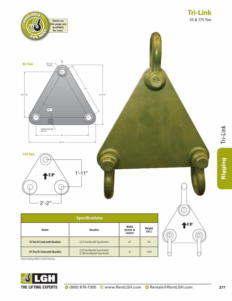
Rigging
277(800) 878-7305 www.RentLGH.com [email protected]
Tri-L
ink
Tri-Link 55 & 175 Ton
Model ShacklesWidth
(Center to Center)
Weight (Lbs.)
55 Ton Tri-Link with Shackles (3) 55 Ton Alloy Bolt Type Shackles 24” 416
175 Ton Tri-Link with Shackles (2) 85 Ton Alloy Bolt Type Shackles(1) 200 Ton Alloy Bolt Type Shackle 26 1,058
Specifications
Green shading reflects rental inventory.
Items onthis page are
availablefor rent.
AVA
ILABLE
FOR RENT
3”
3”
XXXXXXXXXXXXXXX
STAMP PART NO.AND RC
24”
O 2-1/2”TYP.3 PL.
CL
30-1/2”
27-5/16”
24”
20-13/16”
60°
SCALE: 3”=1’0”
upup
2’-2”
1’-11”
SCALE: 3”=1’0”
upup
2’-2”
1’-11”
55 Ton
175 Ton

Rigging
Collector Ring
Collector Ring 150 Ton | 16 Point Crown
278 (800) 878-7305 www.RentLGH.com [email protected]
Items onthis page are
availablefor rent.
AVA
ILABLE
FOR RENT
16 Point Crown - 150t
Notes:- Capacity: 150 Tons- Approx. Weight: 2,200 lbs- All Structural Steel (shapes and plates) shall conform to the following specifications:
- Wide Flange and W/T shapes: ASTM A992- Channels, Angles W/T's and Plates: A36, A572 GR 50- Hollow Structural Sections (HSS): ASTM A500, Grade B (Yeild Stress = 46 KSI)- Pipe (Seamless or Electric Fusion Welded): ASTM A53, Grade B
- Detailing fabrication and erection of structural steel shall conform to the AISC steel construction manual, latest edition.- All weldmetal shall have a minimum tensile strength of 70 KSI.
5434
22.50° Designed To AcceptCrosby G-209 1 1/4"12t Screw Pin Shackles
2312
3518
5112
2514
Designed To AcceptCrosby G-2140 2 1/2"85t Bolt Type Alloy Shackles
Designed To AcceptCrosby G-2130 4"150t Bolt Type Shackle
800.878.7305 | www.lgh-usa.com | [email protected]

Rigging
ROV Shank Hook80 Ton
Modular Spreader Beams
6–1,200 Ton
Master Link7,400 lbs. – 800,000 lbs
Digital Load Link2,200 lbs. –
660,000 lbs.
Shackles2–700 Ton
Turnbuckles500–75,000 lbs.
Tri-Link55 & 175 Ton
Collector Ring150 Ton
Endcap Spreader Beam
9–350 Ton
Telescopic Spreader Beam
2–50 Ton
Lifting Beam1/2–40 Ton
279(800) 878-7305 www.RentLGH.com [email protected]
Pallet Lifter2–3 Ton
Need Additional Rigging Equipment?Please contact LGH today! 800-878-7305 or [email protected]