RIGGING SEILE RIGGING ROPES - Teufelberger · RIGGING SEILE RIGGING ROPES Herstellerinformation und...
156
Art.-Nr.: 6800504 / Ausgabe 02/2016 RIGGING SEILE RIGGING ROPES Herstellerinformation und Gebrauchsanleitung/ Manufacturer's information and instructions for use
Transcript of RIGGING SEILE RIGGING ROPES - Teufelberger · RIGGING SEILE RIGGING ROPES Herstellerinformation und...
Art
.-N
r.: 6
80
050
4 /
Aus
gab
e 0
2/2
016
RIGGING SEILE RIGGING ROPESHerstellerinformation und Gebrauchsanleitung/
Manufacturer's information and instructions for use
2
General ................................................ 4Generic warnings ................................. 5Intended Use ........................................ 6Explanations reg. Product Labelling .... 6Technical Data ..................................... 7Technical Data – Rigging Ropes ............ 9Technical Data – Winch rope ................. 11Technical Data – Loopie, Ploopie, Soft Eye Slings ........... 12Material Properties of Yarns ................ 13Material Properties of Metal parts ...... 14Use and Limitations of Use .................. 15Security ............................................... 17Choice of Equipment ............................ 18Installation and Use ............................. 19Regular Checks .................................... 25Maintenance and Service Life .............. 26Transport, Storage and Cleaning ......... 26Declaration of Conformity .................... 28
Allgemeines ........................................ 30Generelle Hinweise.............................. 31Bestimmungsmäßige Verwendung ...... 32Erklärung zur Kennzeichnung ............. 33Technische Daten ................................ 34Technische Daten - Arbeitsseile/ Bullropes ................ 35Technische Daten - Windenseile ........... 37Technische Daten - Loopie, Ploopie und Soft Eye Schlingen . 38Materialeigenschaftender Garne ......... 39Materialeigenschaften der Metallteile 41Gebrauch und -seinschränkungen ....... 42Sicherheitshinweise ............................ 44Auswahl der Ausrüstung ..................... 45Inbetriebnahme und Anwendung ......... 47Regelmäßige Überprüfung .................. 50Instandhaltung und Lebensdauer ........ 51Transport, Lagerung und Reinigung .... 52Konformitätserklärung ....................... 53
Généralités .......................................... 55Indications générales .......................... 56Utilisation conforme à la destination ... 57Explication du marquage ..................... 57Données techniques ............................ 59Données techniques – Cordes de travail / Bullropes .......... 60Données techniques – Corde de treuillage ........... 63Données techniques – Élingues Loopie, Ploopie et Soft Eye ............................................................. 63Propriétés des matériaux des fils ........ 66Propriétés des matériaux des pièces metalliques.......................................... 68Utilisation et restrictions ..................... 68Consignes à respecter av. utilisation ... 69Choix ................................................. 71Mise en service et utilisation ............... 72Contrôle régulier ................................. 75Entretien et durée de vie ..................... 76Transport, stockage et nettoyage ........ 77Déclaration de conformité ................... 78
Generali ............................................... 80Informazioni generali .......................... 81Utilizzo conforme all’uso previsto ........ 82Illustrazione etichettatura ................... 83Dati tecnici ........................................... 84Dati tecnici – Corde da lavoro/Bullropes 85Dati tecnici – Corde per verricelli .......... 88Dati tecnici – Lacci Loopie, Ploopie e Soft Eye ........................... 88Caratteristiche dei fili .......................... 90Caratteristiche degli elementi di metallo ................................................ 91Utilizzo e limiti di utilizzo ..................... 93Da rispettare prima dell‘utilizzo .......... 94Scelta ................................................. 96Messa in esercizio e applicazione ........ 97Controlli regolari ................................. 100Manutenzione e durata di vita .............. 101Trasporto, immagazzinamento e pulizia ................................................. 101Dichiarazione di conformità ................. 103
DE
INHALT / CONTENT
EN FR
IT

3
INHALT / CONTENT
General ................................................ 105Indicaciones generales ........................ 106Utilización según finalidad prevista ..... 107Explicación del marcado ...................... 108Datos técnicos ...................................... 109Datos técnicos - de cuerdas de trabajo/ cuerdas de apeo Bullrope............................................................. 110Datos técnicos - de cuerda para cabrestante .................. 113Datos técnicos - de eslingas Loopie, Ploopie y con ojo sin guardacabos (Soft Eye) .................... 113Propiedades des material de los hilos . 115Propiedades del material de las Piezas metállicas ................................. 116Utilización y restricciones .................... 118A observar antes del uso ..................... 119Selección ............................................. 121Puesta en servicio y utilización ............ 122Verificación regular ............................. 125Mantenimiento y durabilidad ............... 126Transporte, almacenamiento y limpieza ............................................... 127Declaración de conformidad ................ 128
Obecný ........................................................130Všeobecné pokyny ....................................131Správné použití ..........................................132Vysvětlení značení .....................................133Technické údaje ........................................134Technické údaje – pracovní lana/Bullropes ............... ........................................................135Technické údaje – navijákové lano ...........137Technické údaje – smyčky Loopie, Ploopie a Soft Eye ....................138Materiálové vlastnosti přízí ......................139Materiálové vlastnosti kovových součástek ....................................................141
Použití a omezení .......................................142Pokyny před použitím ...............................144Výběr ..........................................................145Provoz a použití ..........................................146Pravidelná kontrola ...................................150Údržba a životnost .....................................151Transport, skladování a čištění ...............152Prohlášení o shodě výrobku ....................153
ESP
CZ
WARNINGThe use of our products can be dangerous. Our products may only be used for their intended purpose. They must particularly not be used for personal protective equipment as specified in EU directive 89/686/EWG. The customer is responsible that the user has been trained in the safe use of the product and in accompanying safety precau-tions. Be aware of the fact that the product can cause damage if wrongly used, stored, cleaned or overloaded. Check national safety regulations, industry recommendations and standards for local requirements. TEUFELBER-GER® and 拖飞宝® are internationally registered trademarks of the TEUFELBERGER Group.
4
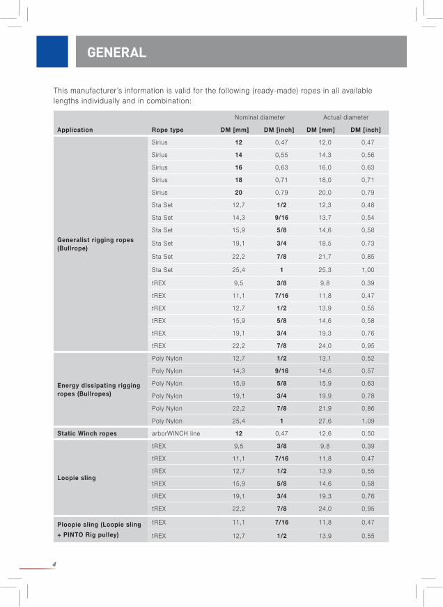
This manufacturer’s information is valid for the following (ready-made) ropes in all available lengths individually and in combination:
GENERAL
Nominal diameter Actual diameter
Application Rope type DM [mm] DM [inch] DM [mm] DM [inch]
Generalist rigging ropes(Bullrope)
Sirius 12 0,47 12,0 0,47
Sirius 14 0,55 14,3 0,56
Sirius 16 0,63 16,0 0,63
Sirius 18 0,71 18,0 0,71
Sirius 20 0,79 20,0 0,79
Sta Set 12,7 1/2 12,3 0,48
Sta Set 14,3 9/16 13,7 0,54
Sta Set 15,9 5/8 14,6 0,58
Sta Set 19,1 3/4 18,5 0,73
Sta Set 22,2 7/8 21,7 0,85
Sta Set 25,4 1 25,3 1,00
tREX 9,5 3/8 9,8 0,39
tREX 11,1 7/16 11,8 0,47
tREX 12,7 1/2 13,9 0,55
tREX 15,9 5/8 14,6 0,58
tREX 19,1 3/4 19,3 0,76
tREX 22,2 7/8 24,0 0,95
Energy dissipating rigging ropes (Bullropes)
Poly Nylon 12,7 1/2 13,1 0,52
Poly Nylon 14,3 9/16 14,6 0,57
Poly Nylon 15,9 5/8 15,9 0,63
Poly Nylon 19,1 3/4 19,9 0,78
Poly Nylon 22,2 7/8 21,9 0,86
Poly Nylon 25,4 1 27,6 1,09
Static Winch ropes arborWINCH line 12 0,47 12,6 0,50
Loopie sling
tREX 9,5 3/8 9,8 0,39
tREX 11,1 7/16 11,8 0,47
tREX 12,7 1/2 13,9 0,55
tREX 15,9 5/8 14,6 0,58
tREX 19,1 3/4 19,3 0,76
tREX 22,2 7/8 24,0 0,95
Ploopie sling (Loopie sling
+ PINTO Rig pulley)
tREX 11,1 7/16 11,8 0,47
tREX 12,7 1/2 13,9 0,55

5
Prior to using this product, read this document thoroughly, make sure you understand the instructions for use. Follow all recommendations, consider under which circumstances and conditions the product wil l be used and whether the product meets the resulting requirements. Keep this manufacturer’s information readily accessible for future reference. Contact the ma-nufacturer TEUFELBERGER Fiber Rope GmbH (contact details on the back of this set of user instructions) if you have any questions.
This product may be util ized only by persons trained in its safe use and having the relevant knowledge, experience and skil ls i.e. competence. Rigging is a higher risk activity than most arborist activities. Therefore, relevant training and knowledge is required prior to carrying out rigging operations. We recommend that the user has attended and completed a relevant and recognized arborist’s training program, e.g. ETT (Certif ied European Tree Technician), ETW (Certif ied Europea Tree Worker), relevant training courses put on by the AA (Arboricultural Association).
Before carrying out rigging work check whether an official permission is needed. Restrict access to the work site and demarcate the site clearly so that no one can enter the site inad-vertently. Recognize and detect the potential risks l ike electric cables.
Failure to follow manufacturer’s instructions especially all warnings and safety in-structions may lead to accidents, property damage, serious injury and possibly death! Rigging carries a high risk of personal injury and damage to property. Any use devi-ating from and any disregard of these instructions will be considered as outside the defined scope of use and therefore not for the defined purpose(s).
Be aware of the need for appropriate or obligatory personal protective equipment (PPE).
Check all relevant legislation regarding rigging and personal protective equipment (PPE) for local requirements.
We regard this manufacturer’s information as “work in progress”. We have simulated dynamic loads on site and will go on working on measurement of dynamic data. The available results are published on our homepage www.teufelberger.com.
GENERIC WARNINGS
GENERIC WARNINGS
Soft Eye sling (single eye)
tREX 9,5 3/8 9,8 0,39
tREX 11,1 7/16 11,8 0,47
tREX 12,7 1/2 13,9 0,55
tREX 15,9 5/8 14,6 0,58
tREX 19,1 3/4 19,3 0,76
tREX 22,2 7/8 24,0 0,95
Nominal diameter Actual diameter
Application Rope type DM [mm] DM [inch] DM [mm] DM [inch]
6
Rigging means the step-by-step dismantling of a tree aided by a rated lift ing system, consisting of texti le ropes, pulleys and (normally) a tree trunk as a natural structure that is capable of withstanding the forces generated by the deceleration created when fall ing tree sections, often of considerable mass, are arrested.
The (ready-made) rope accompanied by these user instructions may be used only for the de-fined purpose(s) as part of a rigging system. It is the user’s responsibil ity to ensure compatibil i-ty of each product component with its neighbouring components.
Note: “The individual components of the system interact in a way that has neither been fully investigated nor understood. Rigging exposes the climber, the equipment and the tree itself to high loads that are diff icult to calculate.”1 It is the user’s responsibil ity to assess and minimize all risks associated with this work.
TEUFELBERGER is not responsible for any direct, indirect, or incidental consequences/damageoccurring during or after the use of the product and resulting from any improper use including alteration of the ropes (preparation of an eye etc.) nor caused by poor compatibil ity with other equipment or poor configuration.
Rigging products must not be used as personal fall protection equipment (PPE).
It is important to mark rigging equipment in such a way that it cannot be confused with, nor used as, PPE. Store climbing and rigging equipment separately.
manufacturer; TEUFELBERGER Fiber Rope GmbH, Vogelweiderstrasse 50, A-4600 WelsType application(cf. table 1)Sirius etc. rope name1 eye splice etc. information about the termination (e.g. 1 eye splice)Polyester etc. fiber materialDM: xx mm nominal diameter in [mm]L_ yy m length in [m]xxxxxxx Art. no. 2016-xxx Serial no.2016 Year of manufacture03 Month of manufacture Symbol indicating that the instructions for use must be read and understood
Rated load the loads printed next to the following icons give an indication of rated load in a defined configuration.
INTENDED USE / PRODUCT LABELLING
EXPLANATIONS REGARDING PRODUCT LABELLING
1 Andreas Detter, „Rigging-Techniken beim Abtragen von Bäumen. Teil 1: Kinematische Analysen“, AFZ-Der Wald 24/2008, S.1322ff.t
INTENDED USE
7
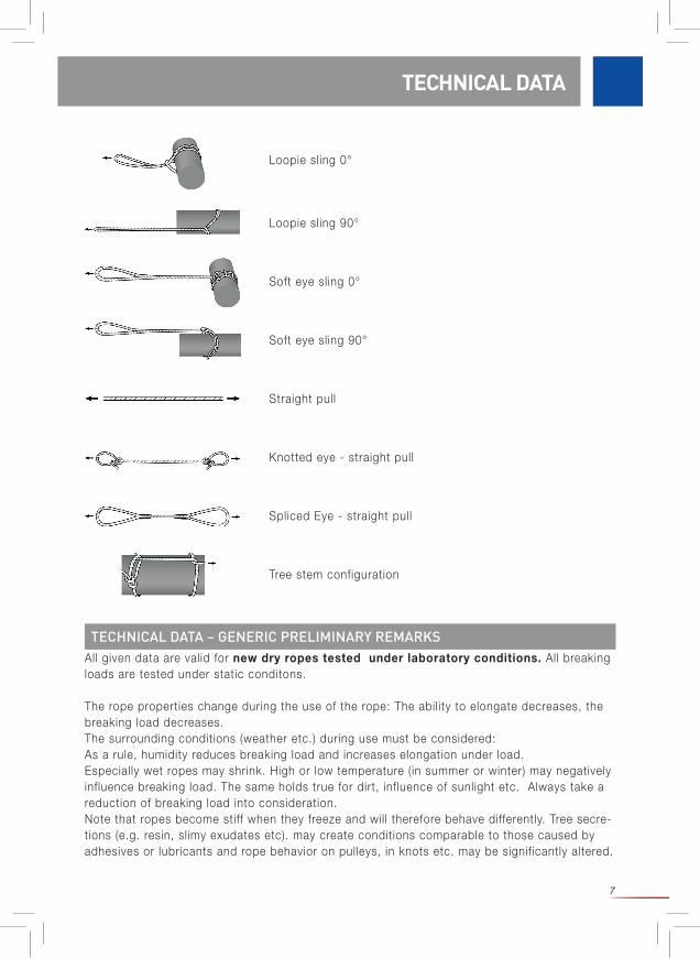
Loopie sling 0°
Loopie sling 90°
Soft eye sling 0°
Soft eye sling 90°
Straight pull
Knotted eye - straight pull
Spliced Eye - straight pull
Tree stem configuration
All given data are valid for new dry ropes tested under laboratory conditions. All breaking loads are tested under static conditons.
The rope properties change during the use of the rope: The abil ity to elongate decreases, the breaking load decreases. The surrounding conditions (weather etc.) during use must be considered: As a rule, humidity reduces breaking load and increases elongation under load. Especially wet ropes may shrink. High or low temperature (in summer or winter) may negatively influence breaking load. The same holds true for dirt, influence of sunlight etc. Always take a reduction of breaking load into consideration. Note that ropes become stiff when they freeze and will therefore behave differently. Tree secre-tions (e.g. resin, slimy exudates etc). may create conditions comparable to those caused by adhesives or lubricants and rope behavior on pulleys, in knots etc. may be significantly altered.
TECHNICAL DATA – GENERIC PRELIMINARY REMARKS
TECHNICAL DATA
8
2 MBL = minimum breaking load 3 Andreas Detter, Chris Cowell et al., „Evaluation of current rigging and dismantling practices used in arboriculture“, Health and Safety Executive Research Report 668, 2008 (http://www.hse.gov.uk/research/rrpdf/rr668.pdf)4 Instead of the mass of the log its weight ought to be used to be physically correct. The weight results from the mass [kg] ]*9,81m/s² and is given as a force in [N]. Simplif ied a mass of 1kg may be taken for 10 N = 1 daN = 0,01 kN.
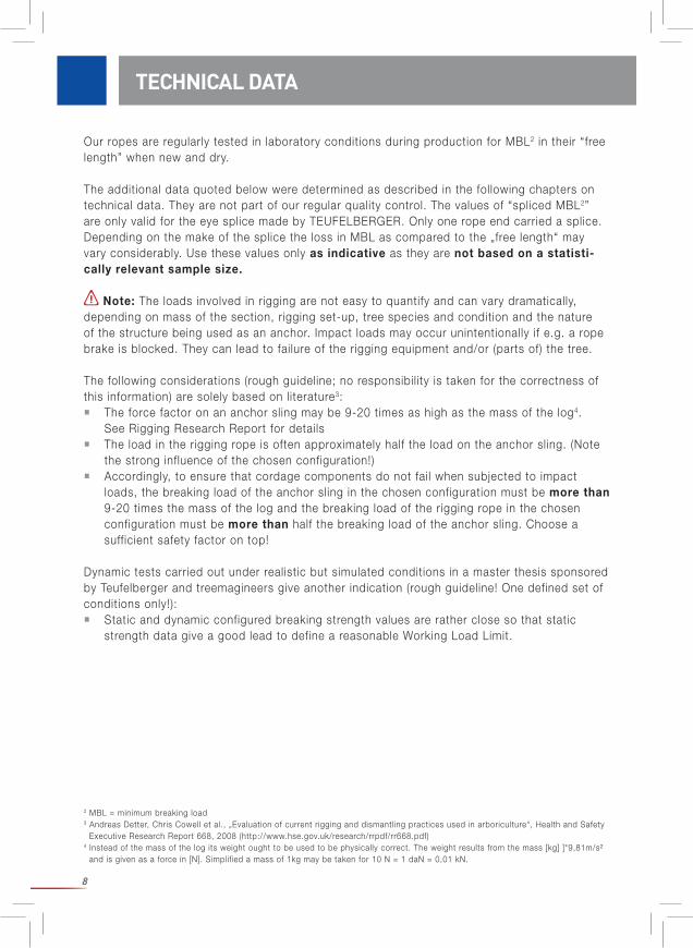
Our ropes are regularly tested in laboratory conditions during production for MBL2 in their “free length” when new and dry.
The additional data quoted below were determined as described in the following chapters on technical data. They are not part of our regular quality control. The values of “spliced MBL2” are only valid for the eye splice made by TEUFELBERGER. Only one rope end carried a splice. Depending on the make of the splice the loss in MBL as compared to the „free length“ may vary considerably. Use these values only as indicative as they are not based on a statisti-cally relevant sample size.
Note: The loads involved in rigging are not easy to quantify and can vary dramatically, depending on mass of the section, rigging set-up, tree species and condition and the nature of the structure being used as an anchor. Impact loads may occur unintentionally if e.g. a rope brake is blocked. They can lead to failure of the rigging equipment and/or (parts of) the tree.
The following considerations (rough guideline; no responsibil ity is taken for the correctness of this information) are solely based on literature3: The force factor on an anchor sling may be 9-20 times as high as the mass of the log4. See Rigging Research Report for details The load in the rigging rope is often approximately half the load on the anchor sling. (Note the strong influence of the chosen configuration!) Accordingly, to ensure that cordage components do not fail when subjected to impact loads, the breaking load of the anchor sling in the chosen configuration must be more than 9-20 times the mass of the log and the breaking load of the rigging rope in the chosen configuration must be more than half the breaking load of the anchor sling. Choose a sufficient safety factor on top!
Dynamic tests carried out under realistic but simulated conditions in a master thesis sponsored by Teufelberger and treemagineers give another indication (rough guideline! One defined set of conditions only!): Static and dynamic configured breaking strength values are rather close so that static strength data give a good lead to define a reasonable Working Load Limit.
TECHNICAL DATA

9
Mind the generic preliminary remarks on technical data, especially on statistical relevance!
The values of „knotted MBL“ are valid for the following configuration: An eye was knotted (dou-bled bowline) at each rope end:
„MBL on stem“ was determined as described in the following pictures:
Information on rope make:
TECHNICAL DATA
TECHNICAL DATA – GENERALIST AND ENERGY DISSIPATING RIGGING ROPES
Sirius Sta Set tREX Poly Nylon
Core Braided polyester Braided polyesterHollow-braided polyester with waxed coating
Braided polya-mide PA6
Cover Braided polyesterBraided polyester with polyurethane
coatingBraided polyester
Pic. 1
Pic. 2 Pic. 3
Typical load-elongation behaviour of the rope along its „free length“:
10
TECHNICAL DATA
max.: 85%
of free length
max.: 45%
of free length
max.: 55%
of free length
Sta Set 1/2 12,3 116 37 32 16 20
Sta Set 9/16 13,7 150 55 47 24 30
Sta Set 5/8 14,6 177 65 55 29 36
Sta Set 3/4 18,5 253 87 74 39 48
Sta Set 7/8 21,7 353 143 122 64 79
Sta Set 1 25,3 482 168 143 75 92
max.: 90%
of free length
max.: 50 %
of free length
max.: 55 %
of free lenght
tREX 3/8 9,8 71 26 23 13 14
tREX 7/16 11,8 100 34 30 17 18
tREX 1/2 13,6 131 44 39 22 24
tREX 5/8 17,4 209 66 59 33 36
tREX 3/4 20,0 271 91 81 45 50
tREX 7/8 23,3 377 128 115 64 70
Rope type
Nominal diameter
[mm][inch]
Actual diameter
[mm]
Nominal weight [g/m]
MBL free length
min. [kN]
MBL spliced
[kN]
MBL knotted
[kN]
MBL stem [kN]
max.: 85%
of free length
max.: 50%
of free length
max.: 59%
of free length
Sirius 12 12,0 103 35 30 18 21
Sirius 14 14,3 151 52 44 26 31
Sirius 16 16,0 185 63 53 32 37
Sirius 18 18,0 227 77 65 39 45
Sirius 20 20,0 285 88 75 44 52
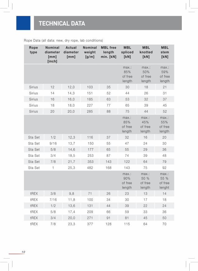
Rope Data (all data: new, dry rope, lab conditions)
11
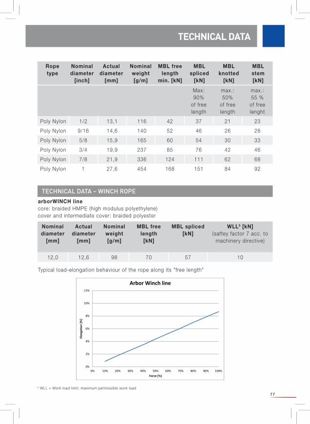
TECHNICAL DATA
TECHNICAL DATA – WINCH ROPEarborWINCH linecore: braided HMPE (high modulus polyethylene)cover and intermediate cover: braided polyester
Nominal diameter
[mm]
Actual diameter
[mm]
Nominal weight [g/m]
MBL free length
[kN]
MBL spliced [kN]
WLL5 [kN](saftey factor 7 acc. to
machinery directive)
12,0 12,6 98 70 57 10
5 WLL = Work load limit; maximum permissible work load
Max: 90%
of free length
max.: 50%
of free length
max.: 55 %
of free lenght
Poly Nylon 1/2 13,1 116 42 37 21 23
Poly Nylon 9/16 14,6 140 52 46 26 28
Poly Nylon 5/8 15,9 165 60 54 30 33
Poly Nylon 3/4 19,9 237 85 76 42 46
Poly Nylon 7/8 21,9 336 124 111 62 68
Poly Nylon 1 27,6 454 168 151 84 92
Rope type
Nominal diameter
[inch]
Actual diameter
[mm]
Nominal weight [g/m]
MBL free length
min. [kN]
MBL spliced
[kN]
MBL knotted
[kN]
MBL stem [kN]
0%
2%
4%
6%
8%
10%
12%
0% 10% 20% 30% 40% 50% 60% 70% 80% 90% 100%
Elon
gatio
n [%
]
Force [%]
Arbor Winch line
Typical load-elongation behaviour of the rope along its "free length"
12
Mind the generic preliminary remarks on technical data, especially on statistical relevance!
All further data were determined as follows. They are not part of our regular quality controle. Use these values only as indicative as they are not based on a statistically relevant sample size.
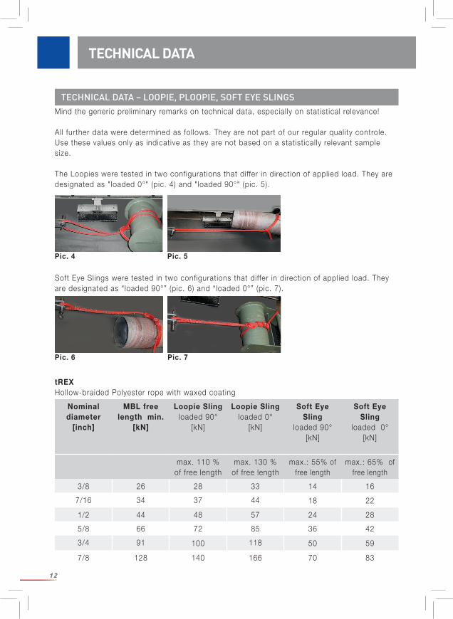
The Loopies were tested in two configurations that differ in direction of applied load. They are designated as "loaded 0°" (pic. 4) and "loaded 90°" (pic. 5).
Soft Eye Slings were tested in two configurations that differ in direction of applied load. They are designated as “loaded 90°” (pic. 6) and “loaded 0°” (pic. 7).
tREXHollow-braided Polyester rope with waxed coating
TECHNICAL DATA
Nominal diameter
[inch]
MBL free length min.
[kN]
Loopie Slingloaded 90°
[kN]
Loopie Slingloaded 0°
[kN]
Soft Eye Sling
loaded 90°[kN]
Soft Eye Sling
loaded 0°[kN]
max. 110 % of free length
max. 130 % of free length
max.: 55% of free length
max.: 65% of free length
3/8 26 28 33 14 16
7/16 34 37 44 18 22
1/2 44 48 57 24 28
5/8 66 72 85 36 42
3/4 91 100 118 50 59
7/8 128 140 166 70 83
Pic. 6 Pic. 7
Pic. 4 Pic. 5
TECHNICAL DATA – LOOPIE, PLOOPIE, SOFT EYE SLINGS
13
TECHNICAL DATA
Nominal diameter
[inch]
MBL free length min.
[kN]
Ploopie Slingloaded 90° [kN]
Ploopie Slingloaded 0°
[kN]
max. 90 % of free length max. 110 % of free length
7/16 34 30 37
1/2 44 39 48
MATERIAL PROPERTIES OF YARNS
Material Polyester (polyethylen-terephthalate)
Polyamide(Polyamide 6)
HMPE(high modulus Polyethylene)
Electrical properties:
Specific electrical resistivity
Ωcm 1011-1014 109-1012
Electrical resistivity Ω >1014
Moisture take-up (standard climate)
% 0,2-0,5 3,5-4,5 0
Chemical resistance
Resistance against acids Good against di-luted mineral acids and organic acids
at room tempe-rature
More suscep-tible to diluted
acids thean Polyester
excellent
Resistance against alkali Sufficient. Concentrated or hot diluted alkali affect the fibre.
Very good resistance
against alkali at room tempera-
ture. Fiber damaged by
high concentra-tion or tempe-
rature.
excellent
Careful with strongly oxidizing
media.
The following data are taken from literature and relate to yarns, i.e. the raw material used for making the ropes. Sources: “Faserstoff-Tabellen nach P.-A. Koch“: Polyester fibers, 1993 and Polyamide fibers, 1997. Fact Sheets by DSM: CIS YA100 and CIS YA102 of 01-01-2008;
The pulley on the ploopies consists mainly from aluminum ASTM 7075 and stainless steel 174PH. The technical data of the loopies ARE NOT valid for the ploopies and adding any pulley to a loopie may change the breaking strength values considerably: For larger diameter ploopies the strength l imiting part is the pulley – so take care of the pulley’s breaking strength. And the loopie’s breaking strength is l ikely to be reduced by the pulley that damages the texti le during strong pull. We have experienced reductions of approx. 15%.
14
MATERIAL PROPERTIES
Characteristics in cold Minor increase in tenacity, strong
decrease in elongation
Very good resi-stance against
cold. Minor increase in
tenacity, strong decrease in elongation
At -60°C 110% of tenacityand
90% of elongati-on as compared
to +23°C
Weathering After 1 year wea-thering 40-47%
(double) bending cycles until brea-
kage.
Medium stabil ity against l ight.
Under real con-ditions (9 months
outdoors) residual tenacity comparable to
Polyester (46%): 47%.
Burning behaviour Does not continue burning, tendency to flamng droplets
Like Polyester. Burns con-siderably if coloured or impregnated
Does not continue burning
Disposal Domestic waste Domestic waste Domestic waste
For information on the metal parts also consult the corresponding user instructions accompa-nying the product. Some values in the below table are taken from material datasheets and have not been measured on the actual product. Certain factors may affect these values (e.g. an anodising layer wil l drastically reduce electrical conductivity).
MATERIAL PROPERTIES OF METAL PARTS
Material Polyester (polyethylen-terephthalate)
Polyamide(Polyamide 6)
HMPE(high modulus Polyethylene)
Avoid contact with chemicals!
Thermal properties:
Thermal conductivity W/mK 0,25 0,24 20 axial0,2 transveral
Melting point °C 250-260 215-220 144-152
Permanent heat resistance °C 120 90 70
15
USE AND LIMITATIONS OF USEBefore using rigging ropes make considerations whether rigging is the most suitable method. Question whether the tree is safe to climb and whether the tree is safe to use as a structure for rigging. Only if the answer to both questions is “yes”, rigging shall be used. Also consider whether it is safer to use machinery (crane, work platform) than to rig the tree.
MATERIAL PROPERTIES
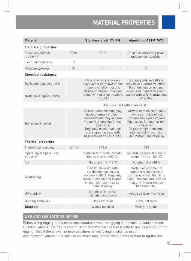
Chemical resistance
Resistance against acidsStrong acids and alkalis
may have a corrosive effect. If contamination occurs,
clean and inspect in accor-dance with user instructions
of pulley
Strong acids and alkalis may have a corrosive effect.
If contamination occurs, clean and inspect in accor-dance with user instructions
of pulley.Resistance against alkali
Avoid contact with chemicals!
Behaviour if soiled
Certain contaminants may have a corrosive effect.
Contaminants may impede the correct function of me-
chanisms. Regularly clean, maintain and inspect in acc. with
user instructions of pulley.
Certain contaminants may have a corrosive effect.
Contaminants may impede the correct function of me-
chanisms.Regularly clean, maintain and inspect in acc. with
user instructions of pulley.
Thermal properties
Thermal conductivity W/mk 178.4 130
Operating temperatures of pulley
Suitable for normal climatic temps (-40 to +50 °C)
Suitable for normal climatic temps (-40 to +50 °C)
Ice No effect if > -40°C No effect if > -40°C
Weathering
Certain environmental conditions may have a
corrosive effect. Regularly clean, maintain and inspect
in acc. with user instruc-tions of pulley.
Certain environmental conditions may have a
corrosive effect. Regularly clean, maintain and inspect
in acc. with user instruc-tions of pulley.
UV stabil ity No effect in normal climatic conditions Anodized layer may fade
Burning behaviour Does not burn Does not burn
Disposal Widely recycled Widely recycled
Material Stainless steel 174 PH Aluminium ASTM 7075
Electrical properties
Specific electrical resistivity
Ωcm 8*106 5.15*106 (Anodizing layer reduces conductivity)
Electrical resistivity Ω
Moisture take-up % 0 0
16
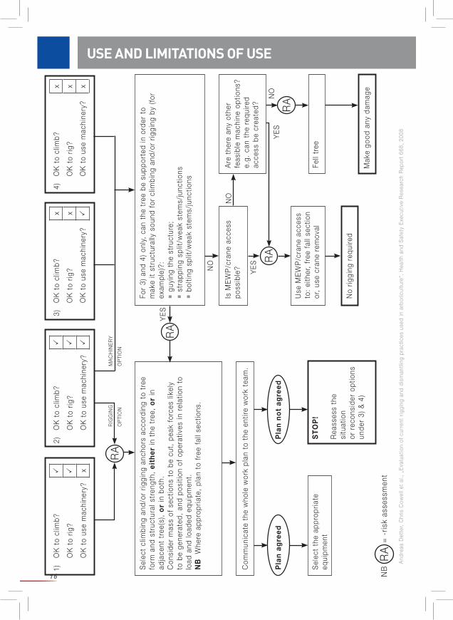
USE AND LIMITATIONS OF USE1)
OK
to
clim
b?
OK
to
rig?
OK
to
use
mac
hine
ry?
x
2)O
K t
o cl
imb?
OK
to
rig?
OK
to
use
mac
hine
ry?
3)O
K t
o cl
imb?
x
OK
to
rig?
x
OK
to
use
mac
hine
ry?
4)O
K t
o cl
imb?
x
OK
to
rig?
x
OK
to
use
mac
hine
ry?
x
Sel
ect
clim
bing
and
/or
riggi
ng a
ncho
rs a
ccor
ding
to
tree
fo
rm a
nd s
truc
tura
l str
engt
h, e
ith
er in
the
tre
e, o
r in
ad
jace
nt t
ree(
s),
or
in b
oth.
Con
side
r m
ass
of s
ectio
ns t
o be
cut
, pe
ak f
orce
s lik
ely
to b
e ge
nera
ted,
and
pos
ition
of
oper
ativ
es in
rel
atio
n to
lo
ad a
nd lo
aded
equ
ipm
ent.
NB
W
here
app
ropr
iate
, pl
an t
o fr
ee f
all s
ectio
ns.
For
3) a
nd 4
) on
ly,
can
the
tree
be
supp
orte
d in
ord
er t
o m
ake
it st
ruct
ural
ly s
ound
for
clim
bing
and
/or
riggi
ng b
y (fo
r ex
ampl
e)?:
g
uyin
g th
e st
ruct
ure;
s
trap
ping
spl
it/w
eak
stem
s/ju
nctio
ns
bol
ting
split
/wea
k st
ems/
junc
tions
Com
mun
icat
e th
e w
hole
wor
k pl
an t
o th
e en
tire
wor
k te
am.
Is M
EW
P/c
rane
acc
ess
poss
ible
?A
re t
here
any
oth
er
feas
ible
mac
hine
opt
ions
? e.
g. c
an t
he r
equi
red
acce
ss b
e cr
eate
d?
Use
ME
WP
/cra
ne a
cces
s to
: ei
ther
, fr
ee f
all s
ectio
n or
, us
e cr
ane
rem
oval
Fell
tree
No
riggi
ng r
equi
red
Sel
ect
the
appr
opria
te
equi
pmen
tS
TO
P!
Rea
sses
s th
e si
tuat
ion
or r
econ
side
r op
tions
un
der
3) &
4)
Pla
n a
gre
edP
lan
no
t ag
reed
RA
RA
RA
RA
YE
S
YE
S
YE
S
NO
NO
NO
MA
CH
INE
RY
OP
TIO
N
RIG
GIN
G
OP
TIO
N
RA
NB
=
-ris
k as
sess
men
t
Mak
e go
od a
ny d
amag
e
And
reas
Det
ter,
Chr
is C
owel
l et
al.,
„E
valu
atio
n of
cur
rent
rig
ging
and
dis
man
tling
pra
ctic
es u
sed
in a
rbor
icul
ture
“, H
ealth
and
Saf
ety
Exe
cutiv
e R
esea
rch
Rep
ort
668,
200
8
17
TO BE OBSERVED PRIOR TO USE
Before rigging operations: Carry out a thorough risk assessment. It is the responsibil ity of the user to ensure that a relevant and ‘l ive’ Risk Assessment is in place during the work being carried out which includes emergency contingencies. Notably, a thorough visual tree inspection must be undertaken. Plan and organize all steps. Note that different sections of the same tree show different behavior. Individual measures and techniques may therefore be necessary. Safe rigging requires team work. Take care that each team member is aware of their scope of responsibil ity. Establish and maintain clear communication between all people involved by introducing unambiguous language, hand signals and by using communication headsets if appropriate. It is strictly forbidden to stay underneath suspended loads. Note that wind can alter the direction of fall of a tree section, rotate it when suspended, or cause the lowering zone to be altered. The work site must be clearly demarcated, with access restricted, so that no one can enter the site inadvertently especially members of the public. Minimize all risks and take measures to prevent accidents. A plan of rescue measures that covers all foreseeable emergencies needs to be in place before this product can be used. Prior to and during use, rescue measures that can be executed safely and effectively must be considered. The situation of each team member must be analyzed. Set appropriate safety factors. Choose a safe rigging technique for your specific application. Choose the appropriate rigging equipment in the appropriate configuration. Take all measures for the safety of the climber! Use the necessary personal protective equipment against fall (PPE)! The climber, and his fall protection PPE, shall be positioned outside the anticipated trajectory of the rigged section and any rigging equipment. Be aware that in case of rope failure heavy recoil may occur with hardware moving upwards in the tree. A particularly critical situation occurs when the log impacts and the tree starts to vibrate. When ‘snatching’ tree sections, the team shall carefully consider the effects of the forces generated on the anchor structure, how the aerial operatives might be negatively affected and what remedial measures would minimize risk to acceptable levels? The climber shall have to establish a means of safe egress from the tree prior to under- taking each cutting and rigging operation. The climber shall carry a handsaw. Be aware of the entire responsibil ity for the planned operations. Be aware that there is a responsibil ity for a Competent Person to plan all rigging operations.
Note: The loads involved in rigging are not easy to quantify and may vary dramatically depending on the mass of the section, rigging set-up, tree species, tree condition and the form of the anchor structure itself. Shock loads may occur unintentionally, e.g. when a brake is blocked. They can lead to failure of the rigging equipment and / or failure of (parts of) the tree.
SECURITY
18
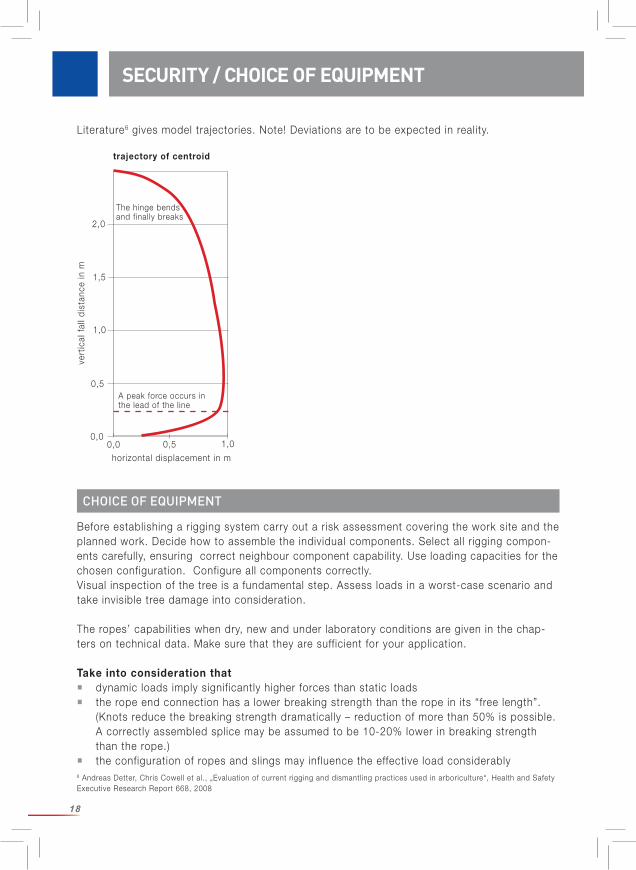
Literature6 gives model trajectories. Note! Deviations are to be expected in reality.
CHOICE OF EQUIPMENT
Before establishing a rigging system carry out a risk assessment covering the work site and the planned work. Decide how to assemble the individual components. Select all rigging compon-ents carefully, ensuring correct neighbour component capabil ity. Use loading capacities for the chosen configuration. Configure all components correctly.Visual inspection of the tree is a fundamental step. Assess loads in a worst-case scenario and take invisible tree damage into consideration.
The ropes’ capabil it ies when dry, new and under laboratory conditions are given in the chap-ters on technical data. Make sure that they are sufficient for your application.
Take into consideration that dynamic loads imply significantly higher forces than static loads the rope end connection has a lower breaking strength than the rope in its “free length”. (Knots reduce the breaking strength dramatically – reduction of more than 50% is possible. A correctly assembled splice may be assumed to be 10-20% lower in breaking strength than the rope.) the configuration of ropes and slings may influence the effective load considerably 6 Andreas Detter, Chris Cowell et al., „Evaluation of current rigging and dismantling practices used in arboriculture“, Health and Safety Executive Research Report 668, 2008
horizontal displacement in m
vert
ical
fal
l dis
tanc
e in
m
0,00,0
0,5 1,0
0,5
1,0
1,5
2,0
A peak force occurs in the lead of the l ine
The hinge bends and finally breaks
trajectory of centroid
SECURITY / CHOICE OF EQUIPMENT
19
all plans and actions should be based on a worst-case scenario and take unforeseen events into account.
Dynamic loading occurs when a fall ing/swinging load is dropped into rigging. The more rapidly or suddenly the load is arrested, the greater the dynamic load generated. In such cases the dynamic load may easily be equivalent to many times the static load.Operations must be planned in a way to minimize and/or effectively manage dynamic loads. Carefully consider the load capacity of the anchor slings as the exerted forces can be more than double the forces on the rigging rope.
A Competent Person who is trained in calculating / estimating rigging forces, and must know the relationship between section mass, fall distance, rope type, rope length and further relevant factors, must be present on site and manage rigging operations.
Studies7 show that the forces at the anchor sling are about 9-20 times as high as the section mass. Warning! This is just a rough indication.
Make sure that the performance of the rope is suitable and adequate for the intended use!
Chose a relevant safety factor. Consult the “International Guidelines on the Safer Use of Fiber Rope“ (CI 1401) of the Cordage Institute for recommendations on safety factors. To be down-loaded free of charge at www.ropecord.com. The machinery directive 2006/42/EC indicates use of a minimum safety factor (ratio of MBL of new rope in its free length to static work load) of 7 for hoisting. Literature suggests multiplying any estimated load by a factor of 1.58.
Note: The system is only as strong as the weakest component involved.
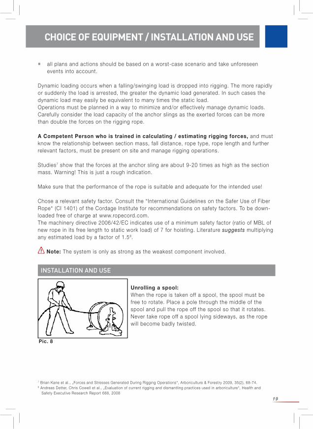
Unrolling a spool:When the rope is taken off a spool, the spool must be free to rotate. Place a pole through the middle of the spool and pull the rope off the spool so that it rotates. Never take rope off a spool lying sideways, as the rope wil l become badly twisted.
INSTALLATION AND USE
7 Brian Kane et al., „Forces and Stresses Generated During Rigging Operations“, Arboriculture & Forestry 2009, 35(2), 68-74. 8 Andreas Detter, Chris Cowell et al., „Evaluation of current rigging and dismantling practices used in arboriculture“, Health and Safety Executive Research Report 668, 2008
CHOICE OF EQUIPMENT / INSTALLATION AND USE
Pic. 8
20
Uncoiling: When removing a rope from a coil, one should start with the end from the inside. The rope should run out counter-clockwise. If the rope is pulled out clockwise, kinks wil l occur. If that happens, re-place the length of rope back into the coil, turn the coil over and pull from the center again. Now the rope should run out counter-clockwise and thus kink-free.
Knots:
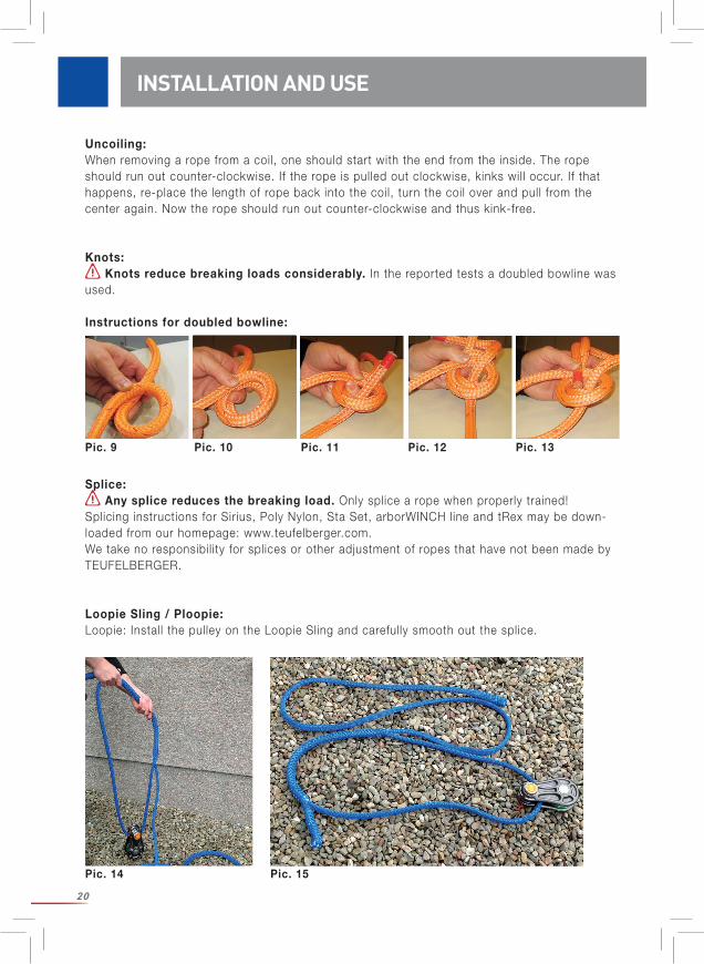
Knots reduce breaking loads considerably. In the reported tests a doubled bowline was used.
Instructions for doubled bowline:
Splice:
Any splice reduces the breaking load. Only splice a rope when properly trained!Splicing instructions for Sirius, Poly Nylon, Sta Set, arborWINCH line and tRex may be down-loaded from our homepage: www.teufelberger.com.We take no responsibil ity for splices or other adjustment of ropes that have not been made by TEUFELBERGER.
Loopie Sling / Ploopie:Loopie: Install the pulley on the Loopie Sling and carefully smooth out the splice.
INSTALLATION AND USE
Pic. 9 Pic. 10 Pic. 11 Pic. 12 Pic. 13
Pic. 14 Pic. 15
21
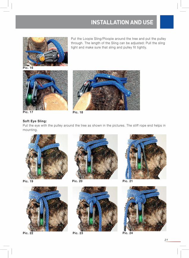
Put the Loopie Sling/Ploopie around the tree and put the pulley through. The length of the Sling can be adjusted: Pull the sling tight and make sure that sling and pulley fit tightly.
Soft Eye Sling: Put the eye with the pulley around the tree as shown in the pictures. The stiff rope end helps in mounting.
INSTALLATION AND USE
Pic. 16
Pic. 17 Pic. 18
Pic. 19 Pic. 20 Pic. 21
Pic. 22 Pic. 23 Pic. 24
22
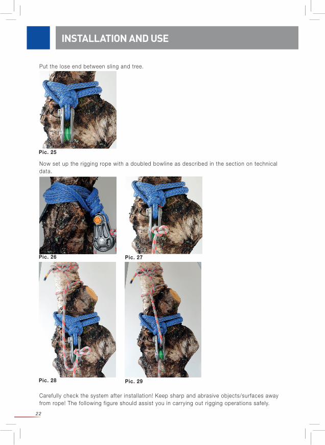
Put the lose end between sling and tree.
Now set up the rigging rope with a doubled bowline as described in the section on technical data.
Carefully check the system after installation! Keep sharp and abrasive objects/surfaces away from rope! The following figure should assist you in carrying out rigging operations safely.
INSTALLATION AND USE
Pic. 25
Pic. 26 Pic. 27
Pic. 28 Pic. 29
23
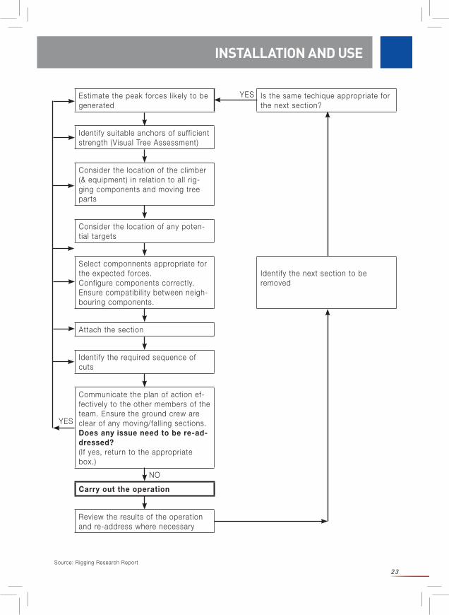
INSTALLATION AND USE
Estimate the peak forces likely to be generated
Is the same techique appropriate for the next section?
Identify suitable anchors of sufficient strength (Visual Tree Assessment)
Consider the location of the climber (& equipment) in relation to all rig-ging components and moving tree parts
Consider the location of any poten-tial targets
Select componnents appropriate for the expected forces.Configure components correctly.Ensure compatibil ity between neigh-bouring components.
Identify the next section to be removed
Attach the section
Identify the required sequence of cuts
Communicate the plan of action ef-fectively to the other members of the team. Ensure the ground crew are clear of any moving/fall ing sections.Does any issue need to be re-ad-dressed?( If yes, return to the appropriate box.)
Carry out the operation
Review the results of the operation and re-address where necessary
YES
YES
NO
Source: Rigging Research Report
24
Options to minimize the effective forces in rigging reduce the log mass reduce the log length install the anchor block as close as practicable to the notch establish an anchor above the section to be rigged (in the same tree or in neighbouring trees/structures) avoid slack in the rigging ropes.
NOTE: These are basic recommendations. There may be reasons not to use these strate-gies in your special application.
Reduce pendulum swing where possible!
Rotation of the rope along its axis reduces service l ife! The cover pattern of Sirius ropes helps identify twist.
Ropes of higher elongation can take up more energy. All ropes increase in length – a longer rope does so more than a short one. The higher the applied load the more elongation of the rope. Bear in mind that elongation implies risk! An elongated rope can move the load in an unfore-seeable or dangerous way. An elongated rope can recoil and cause serious injury. Never wind a rope around your hand or body. Be sure not to stand on rigging ropes during rigging operations. Keep branches, tools and other items clear of fast moving rigging ropes.Fall distance is increased due to elongation of the rope. Control of rigged sections may be more diff icult with ropes of higher elongation.
Note when using winch rope: Never stand in l ine with rope under tension. Under high tension enormous energy is stored in the rope due to the elasticity of the synthetic material. High danger is involved when persons stand in l ine with the rope under excessive tension. If the rope fails, it can recoil with consi-derable force potentially causing serious or fatal injury.Inform all site staff of this hazard. Ensure all site staff and the public are kept clear of the danger area(s).If a rope is frequently twisted in one direction, as e.g. in the use on a winch, it should be used in the opposite direction at times.
Use with further equipment:It must be ensured that the recommendations for use with other components are complied with. Ensure that all components are compatible. Particularly, the ratio D/d of pulley diameter D to rope diameter d must be as large as possible the diameter of the pulley groove must be adequate for the rope diameter. ensure that all components are configured correctly.
Failure to do so increases risk serious injury or fatality.
INSTALLATION AND USE
25
REGULAR CHECKS
WARNING – SAFETY INDICATION
Generally speaking: If there is the slightest doubt about the suitabil ity of the product to perform its required task, the product must to be retired or quarantined and then subjected to testing by a competent person. It must only be returned to service if a competent person has approved its further use in writing after testing.
After a shock load it may be necessary to retire the rope. The rope’s abil ity to dissipate dynamic loads is reduced by use under normal and shock loa-ding. A used rope is not as elastic as a new one and therefore cannot dissipate as much energy. The peak forces in rigging operations therefore increases. The breaking load of the rope decreases at the same time.
Prior and after each use, this product must be subject to inspection as described below: Prior and after each use, the product must be subject to visual and tactile inspection to verifyits integrity, readiness for use and proper functioning.
Inspect the rope visually from all sides and along its entire length. Feel along the rope (tactile check) in order to detect any hidden core damage that might have been caused by excessive bending or local overloading. Note rope sections that have been thermally damaged (glassy rope surface). This may have been caused by high friction in the system. Pay particular attention to the rope section used in the half-hitch on the log. This part of the rope is usually the most damaged one. It may be necessary to cut off this part of the rope and make a new splice or use the other rope end. If in doubt, withdraw from service!
Avoid using a rope that shows signs of aging and wear. Only use ropes in acceptable con-dition that are free from cuts, knots or worn strands. Avoid rope abrasion on rough surfaces. Try to ensure the rope wears evenly along its’ entire length. Never join a broken rope - retire it from service!
We recommend keeping record of use (date, duration, conditions) and inspections (date, exa-miner, distinctive features). Consult all relevant regulations for inspection intervals if applicable.
Always check the entire rope including terminations and hardware!
If there is the slightest doubt, the product must be withdrawn from service or in-spected by an expert.
REGULAR CHECKS

26
Checklist: This inspection must comprise: Inspection of the general condition: age, completeness, dirt, correct composition. Inspection of the labels: Present? Is all information legible? Is year of production identif iable? Inspection of the individual parts for mechanical damage such as cuts, cracks, notches, abrasion, deformation, ribbing, twisting, flattening, thick places. Inspection of all individual parts for damage caused by heat or chemicals such as fusion, hardening, stiffness, discoloration. Inspection of the metal parts for corrosion and deformation. Inspection of the completeness of the end connections, seams (e.g. no abrasion of sewing thread), splices (e.g. no slippage), knots present.
The equipment must be inspected regularly: your safety depends on the effectivenessand durabil ity of the equipment.
Additional information can be found in document CI 2001 — Fiber Rope Inspection and Retirement Criteria – of the Cordage Institute. To be downloaded free of charge at www.ropecord.com.
Only the manufacturer is permitted to carry out repairs.
Actual useful l ife depends solely on the condition of the product which is influenced by various factors (see below). The lifespan could be as short as first use under extreme conditions, or even less if damaged (e.g. in transit) prior to first use.Only if the rope is rarely used (one week a year) and stored correctly (see the section on trans-port, storage and cleaning) can its useful l ife be up to 5 years from date of manufacture. The year of manufacture can be depicted from the product label. If it is not possible to clearly state the age of the rope, it must be retired.
Mechanical wear or other influences such as the effects of sunlight seriously reduce useful l ife. Bleached or abraded fibres, discolouring and hardening are a clear sign that the product should be withdrawn from use. Consult the chapter “Regular Checks”.
TEUFELBERGER expressly refrains from making any general statements about the useful l ife of the product, since it depends on a variety of factors such as UV light, the type and frequency of use, treatment, the effects of weathering such as ice or snow, the environment such as salt, sand, battery acid, thermal strain (exceeding normal climatic conditions), mechanical deforma-tion and many more factors.
Always check the entire rope including terminations and hardware!If there is the slightest doubt, the product must be withdrawn from service or inspected by an expert.
MAINTENANCE
SERVICE LIFE
REGULAR CHECKS / MAINTENANCE / SERVICE LIFE

27
The rope should always be protected against l ight and dirt and placed in appropriatepackaging (moisture resistant, l ight impermeable material) during transport.
Storage conditions: protected against the UV radiation (l ight, welding equipment, ...), dry and clean at room temperature (15-25 °C) not in the proximity of chemicals (acids, lyes, l iquids, vapours, gases,…) and other aggressive environments protected against sharp-edged objects
Therefore, store rope products in a dry and ventilated environment away from light. Avoid twi-sting of the rope!Keep the product clean! Dirt can damage the rope. Damp dirty ropes may rot.
For cleaning, use lukewarm water and – if available – a rope detergent in accordance with the cleaning instructions provided thereon. Do not use a texti le detergent. Following cleaning, rinse the product with plenty of clear water. Alternatively, you can use benzine for cleaning. Be sure to observe the applicable safety rules for the use of benzine. In any event, prior to storage or use, allow the product to dry completely in a natural way and not in direct sunlight, or near fires or other heat sources.
For disinfection, use only such substances that do not have an impact on the synthetic materials used. Do not disinfect the product more often than is absolutely necessary! We recommend the use of isopropyl alcohol 70%. Apply the disinfectant to the surface for about 3 minutes and allow the product to dry naturally. Be sure to observe the safety instructions for the use of the disinfectant.
If you fail to observe these provisions, you may be putting yourself and others in danger!
TRANSPORT, STORAGE AND CLEANING
TRANSPORT, STORAGE AND CLEANING
28
DECLARATION OF CONFORMITY FOR THE ROPE MASTER LENGTH
Generic denomination a) Sirius 12 / 14 / 16 / 18 / 20mmb) arborWINCH line 12mm
Function Rope for l ift ing purposes to be use in rigging operations
Model See generic denomination
Type a) braided cover-core rope made of PES/PESb) braided cover-core rope made of HMPE/PES with an intermediate PES cover
Serial number See label of the rope master length
Commercial name See generic denomination
The company: TEUFELBERGER Fiber Rope GmbH Vogelweiderstr. 50 A-4600 Welshereby declares that the machinery described below:
fulfi ls all the relevant provisions of the Machinery Directive 2006/42/EC as amended.
Wels, January 20th, 2016 Wels, January 20th, 2016
Person authorised to compile the Person empowered to draw up thetechnical file: declaration on behalf of the manufacturer:DI. Rudolf Kirth Rainer Morawa, MBATechnical Director Fiberrope President FiberropeTEUFELBERGER Fiber Rope GmbH TEUFELBERGER Fiber Rope GmbHVogelweiderstraße 50 Vogelweiderstraße 50A-4600 Wels A-4600 Wels
DECLARATION OF CONFORMITY

29
The company: TEUFELBERGER Fiber Rope Corp. 848 Airport Road Fall River, MA 02720-4735, USAhereby declares that the machinery described below:
fulfi ls all the relevant provisions of the Machinery Directive 2006/42/EC as amended.
Fall River, January 20th, 2016 Fall River, January 20th, 2016
Person authorised to compile the Person empowered to draw up thetechnical file: declaration on behalf of the manufacturer:John Tedder Chris LavinTechnical Director PresidentTEUFELBERGER Fiber Rope Corp. TEUFELBERGER Fiber Rope Corp.848 Airport Road 848 Airport RoadFall River, MA 02720-4735, USA Fall River, MA 02720-4735, USA
Generic denomination a) Sta Set ½ / 9/16 / 5/8 / ¾ / 7/8 1 inchb) tREX 3/8 / 7/16 / ½ / 5/8 / ¾ / 7/8 inchc) Poly Nylon ½ / 9/16 / 5/8 / ¾ / 7/8 / 1 inch
Function Rope for l ift ing purposes to be use in rigging operations
Model See generic denomination
Type a) braided cover-core rope made of PES/PES with polyurethane coatingb) hollow-braided PES rope with waxed coatingc) braided cover-core rope made of PA6/PES
Serial number See label of the rope master length
Commercial name See generic denomination
DECLARATION OF CONFORMITY
30
Diese Herstellerinformation und Gebrauchsanleitung gilt für folgende (konfektionierte) Seile in allen l ieferbaren Längen einzeln und in Kombination:
ALLGEMEINES
Nenndurchmesser Istdurchmesser
Anwendung Seiltype DM [mm] DM [inch] DM [mm] DM [inch]
Allgemeine Arbeits-seile (Bullrope)
Sirius 12 0,47 12,0 0,47
Sirius 14 0,55 14,3 0,56
Sirius 16 0,63 16,0 0,63
Sirius 18 0,71 18,0 0,71
Sirius 20 0,79 20,0 0,79
Sta Set 12,7 1/2 12,3 0,48
Sta Set 14,3 9/16 13,7 0,54
Sta Set 15,9 5/8 14,6 0,58
Sta Set 19,1 3/4 18,5 0,73
Sta Set 22,2 7/8 21,7 0,85
Sta Set 25,4 1 25,3 1,00
tREX 9,5 3/8 9,8 0,39
tREX 11,1 7/16 11,8 0,47
tREX 12,7 1/2 13,9 0,55
tREX 15,9 5/8 14,6 0,58
tREX 19,1 3/4 19,3 0,76
tREX 22,2 7/8 24,0 0,95
Arbeitsseile (Bull-ropes) mit höherer Energieaufnahme
Poly Nylon 12,7 1/2 13,1 0,52
Poly Nylon 14,3 9/16 14,6 0,57
Poly Nylon 15,9 5/8 15,9 0,63
Poly Nylon 19,1 3/4 19,9 0,78
Poly Nylon 22,2 7/8 21,9 0,86
Poly Nylon 25,4 1 27,6 1,09
Windenseil arborWINCH line 12 0,47 12,6 0,50
ACHTUNGDie Verwendung der Produkte kann gefährlich sein. Unsere Produkte dürfen nur für den Einsatz verwendet werden, für den sie bestimmt sind. Sie dürfen insbesondere nicht zur Personensicherung im Sinne der EU-RL 89/686/EWG verwendet werden. Der Kunde muss dafür sorgen, dass die Verwender mit der korrekten Anwendung und den notwendigen Sicherheitsvorkehrungen vertraut sind. Bedenken Sie, dass jedes Produkt Schaden verursachen kann, wenn es falsch verwendet, gelagert, gereinigt oder überlastet wird. Prüfen Sie nationale Sicherheitsbestimmungen, Industrieempfehlungen und Normen auf lokal geltende Anforderungen. TEUFELBERGER® und 拖飞宝® sind international registrierte Marken der TEUFELBERGER Gruppe.
31
Vor Verwendung lesen und verstehen Sie diese Gebrauchsanleitung. Befolgen Sie die Empfeh-lungen und überlegen Sie, unter welchen Bedingungen Sie das Produkt einsetzen wollen und ob es dafür geeignet ist. Bewahren Sie diese Herstellerinformation beim Produkt auf für spä-teres Nachschlagen! Bei Fragen wenden Sie sich an den Hersteller TEUFELBERGER Fiber Rope GmbH (Kontaktdaten auf der Rückseite dieser Gebrauchsanleitung).
Dieses Produkt darf nur von Personen verwendet werden, die in seiner sicheren Benutzung unterwiesen sind und entsprechende körperliche und geistige Kenntnisse und Fähigkeiten vorweisen, die also kompetent sind. Rigging-Arbeiten sind mit einem höheren Risiko verbunden als die meisten anderen Baumpflegetätigkeiten. Daher ist auch ein höherer Ausbildungsgrad erforderlich. Wir empfehlen, dass Anwender eine einschlägige anerkannte Ausbildung in Baum-pflege absolviert haben, z.B. ETT (Certif ied European Tree Technician), ETW (Certif ied Europea Tree Worker), einschlägige Trainings der AA (Arboricultural Association).
Vor der Durchführung von Rigging-Arbeiten überprüfen Sie, ob behördliche Genehmigungen dafür nötig sind. Sperren Sie den Einsatzort weiträumig und eindeutig ab, sodass niemand, speziell kein Passant, unbeabsichtigt den Gefahrenbereich betreten kann! Achten Sie auf das Vorhandensein von elektrischen Leitungen oder ähnlichen potentiellen Gefahren!
Das Nichtbefolgen der Anweisungen des Herstellers, insbesondere aller Warn- und Sicherheitshinweise, kann Unfälle, Sachschäden, schwere Verletzungen und eventuell
GENERELLE HINWEISE
GENERELLE HINWEISE
Loopie Schlinge
tREX 9,5 3/8 9,8 0,39
tREX 11,1 7/16 11,8 0,47
tREX 12,7 1/2 13,9 0,55
tREX 15,9 5/8 14,6 0,58
tREX 19,1 3/4 19,3 0,76
tREX 22,2 7/8 24,0 0,95
Ploopie Schlinge (Loopie Schlinge + PiNTO Rig-Rolle)
tREX 11,1 7/16 11,8 0,47
tREX 12,7 1/2 13,9 0,55
Soft Eye Schlinge (ein Auge)
tREX 9,5 3/8 9,8 0,39
tREX 11,1 7/16 11,8 0,47
tREX 12,7 1/2 13,9 0,55
tREX 15,9 5/8 14,6 0,58
tREX 19,1 3/4 19,3 0,76
tREX 22,2 7/8 24,0 0,95
Nenndurchmesser Istdurchmesser
Anwendung Seiltype DM [mm] DM [inch] DM [mm] DM [inch]
32
sogar den Tod zur Folge haben! Bei Rigging-Arbeiten ist die Gefahr von Verletzungen und Sachbeschädigungen sehr hoch. Jeder von diesen Anweisungen abweichende Gebrauch und jede Nichtbeachtung dieser Anweisungen wird als außerhalb des defi-nierten Anwendungsbereichs liegend und daher nicht für den(die) definierten Zweck(e) erachtet.
Wählen Sie für den von Ihnen vorgesehenen Einsatzzweck geeignete oder gesetzlich vorge-schriebene persönliche Schutzausrüstung (PSA).
Beachten Sie relevante (nationale) Sicherheitsbestimmungen zu Rigging und zur Wahl der PSA!
Wir betrachten diese Gebrauchsanleitung als „work in progress“. Wir haben an unserem Stand-ort dynamische Lasten simuliert und werden diese Arbeit mit Messungen dynamischer Daten fortführen. Die verfügbaren Ergebnisse werden auf unserer Homepage www.teufelberger.com veröffentlicht
Unter Rigging versteht man das schrittweise Abtragen eines Baumes mit Hilfe eines berechne-ten Hebesystems aus texti len Seilen, Rollen und (in der Regel) dem Baumstamm als natürlicher Hilfsstruktur, das so ausgelegt ist, dass es den Kräften, die beim Auffangen fallender Baumteile durchaus hoher Masse auftreten, standhält.
Das (konfektionierte) Seil, dem diese Herstellerinformation beil iegt, ist ausschließlich für die Verwendung als Teil eines Systems für Rigging-Arbeiten bestimmt. Es l iegt im Verantwortungs-bereich des Benutzers, die Kompatibil ität jeder Komponente eines Produkts mit ihren benach-barten Komponenten sicherzustellen.
Beachten Sie: „Die einzelnen Komponenten des Systems stehen dabei miteinander in einer Wechselwirkung, die noch nicht vollständig untersucht und verstanden ist. Beim Rigging wer-den Kletterer, Ausrüstung und der Baum selbst großen Belastungen ausgesetzt, die schwer zu kalkulieren sind.“1 Es ist Aufgabe des Anwenders, das damit verbundene Risiko abzuschätzen und zu minimieren.
TEUFELBERGER ist nicht verantwortl ich für direkte, indirekte oder zufäll ige Folgen / Schäden, die während oder nach der Verwendung des Produktes auftreten und die aus nicht bestim-mungsgemäßer Verwendung einschließlich Veränderung der Seile (Fertigen eines Auges etc.), fehlerhafte Kombination mit anderen Komponenten oder ungünstiger Anordnung, resultieren.
Rigging-Produkte dürfen nicht als persönliche Schutzausrüstung (PSA) verwendet werden.
Es ist wichtig, Rigging-Seile und die übrige Baumkletterausrüstung getrennt aufzubewahren und zu kennzeichnen, um Verwechslungen, insbesondere mit PSA auszuschließen.
VERWENDUNG
1 Andreas Detter, „Rigging-Techniken beim Abtragen von Bäumen. Teil 1: Kinematische Analysen“, AFZ-Der Wald 24/2008, S.1322ff.
BESTIMMUNGSMÄSSIGE VERWENDUNG
33
Hersteller und Anschrift: Teufelberger Fiber Rope GmbH Vogelweiderstr. 50, 4600 Wels, AustriaType Gibt die zulässige Anwendungsart an (vgl. Tabelle 1)Sirius etc. Bezeichnung des Seiles1 eye splice etc. Information über die Endverbindung (z.B. ein Augspleiß)Polyester etc. Fasermaterial DM: xx mm Nenndurchmesser in [mm] und/oder [inch]L: yy m Länge in [m]xxxxxxx Artikelnummer2016-xxx Seriennummer2016 Herstell jahr03 Herstellmonat Hinweis, dass die Herstellerinformation gelesen und verstanden werden muss. Rated load Die neben den folgenden Symbolen angeführten Lastwerte geben die Nenn- last in einer definierten Konfiguration an.
Loopie Schlinge 0°
Loopie Schlinge 90°
Soft eye Schlinge 0°
Soft eye Schlinge 90°
Gerader Zug
Geknüpftes Auge - gerader Zug
Gespleißtes Auge - gerader Zug
ERKLÄRUNG ZUR KENNZEICHNUNG
KENNZEICHNUNG
34
TECHNISCHE DATEN
Konfiguration am Baumstamm
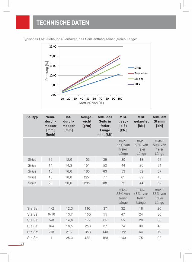
Alle folgenden Daten gelten für neue trockene Seile unter Laborbedingungen. Alle Bruch-lastangaben gelten unter statischen Bedingungen.
In der Anwendung beim Rigging sind Witterungseinflüsse zu berücksichtigen: Nässe reduziert in der Regel die Bruchkraft und erhöht die Dehnung des Seiles unter Last. Insbesondere nasse Seile können schrumpfen. Ebenso beeinflussen hohe bzw. tiefe Temperaturen (im Sommer bzw. Winter) die Bruchkraft des Seiles. Gleiches gilt für Verschmutzungen des Seiles, Einfluss von Sonnenlicht etc. Gehen Sie prinzipiell von einer Senkung der Bruchkraft aus! Bedenken Sie, dass Seile durch Vereisung steif werden und sich dann anders verhalten!Baumsekrete (z.B. Harze, klebrige Exsudate usw.) können Bedingungen schaffen wie sie durch Klebstoffe oder Schmiermittel verursacht werden, sodass sich das Verhalten der Seile auf Rol-len, in Knoten usw. deutlich ändern kann.
Unsere Seile werden regelmäßig auf MBL2 in freier Länge (neu, trocken, Laborbedingungen) getestet.
Die unten angeführten zusätzlichen Daten wurden wie in den folgenden Kapiteln über tech-nische Daten beschrieben ermittelt. Sie sind nicht Teil unserer regelmäßigen Qualitätskontrolle. Die Werte „MBL gespleißt“ gelten nur für den von TEUFELBERGER hergestellten Augspleiß. Nur ein Seilende war mit einem Spleiß versehen. Je nach Ausführung des Spleißes kann die Einbuße an MBL verglichen mit dem Wert für die „freie Länge“ beträchtlich schwanken. Verwen-den Sie diese Daten als grobe Richtwerte, da sie nicht auf einer statistisch relevanten Stichprobengröße beruhen.
Beachten Sie: Die Lasten, die beim Rigging auftreten können, sind nicht leicht zu quanti-fizieren und können sich dramatisch unterscheiden je nach Masse des Baumstückes, Rigging-Set-Up, Baumart, Zustand des Baumes und Beschaffenheit der Ankerstruktur. Lastspitzen können unbeabsichtigt auftreten, wenn beispielsweise das Bremsgerät blockiert. Sie können zum Versagen des Rigging-Equipment und / oder zum Abbrechen von Baum(teilen) führen.
Die folgenden Überlegungen (grobe Leitl inie; für die Richtigkeit dieser Informationen wird keine Verantwortung übernommen) beruhen lediglich auf Literaturangaben3. Die in Tests gemessene Belastung an der Ankerschlinge war je nach Anordnung und tatsächlichem Szenario etwa 9 bis 20 Mal so hoch wie die Masse des Baumstückes4.
2 MBL = Mindestbruchlast 3 Andreas Detter, Chris Cowell et al., „Evaluation of current rigging and dismantling practices used in arboriculture“, Health and Safety Executive Research Report 668, 2008 S. 234 ff. (http://www.hse.gov.uk/research/rrpdf/rr668.pdf)4 Anstelle der Masse des Baumstückes müsste physikalisch korrekt das Gewicht des Baumstückes herangezogen werden. Dieses ergibt sich als Masse[kg]*9,81m/s² und ist eine Kraft in [N]. Vereinfacht lässt sich eine Masse von 1kg gleichsetzen mit etwa 10 N = 1 daN = 0,01 kN.
TECHNISCHE DATEN – GENERELLE WICHTIGE VORBEMERKUNG

35
TECHNISCHE DATEN
Details sind dem Rigging Research Report zu entnehmen Die Belastung im Arbeitsseil ist oft etwa halb so groß wie die Belastung in der Anker- schlinge. (Achtung: Starke Abhängigkeit von der gewählten Konfiguration!) Damit die Seilkomponenten bei einem Sturz nicht versagen, muss die Bruchlast der Ankerschlinge in der gewählten Konfiguration größer als das 9-20-fache der Masse des Baumstamms und die Bruchlast des Arbeitsseils in der gewählten Konfiguration größer als die Hälfte der Bruchlast der Ankerschlinge sein. Wählen Sie darüber hinaus einen ausreichenden Sicherheitsfaktor!
Dynamische Tests, die unter praxisnahen, wenn auch simulierten Bedingungen im Rahmen einer von Teufelberger und treemagineers betreuten Diplomarbeit durchgeführt wurden, l iefern andere Richtwerte (Grobe Leitl inie! Nur ein definierter Satz von Bedingungen!): Statische und dynamische konfigurierte Bruchfestigkeitswerte l iegen ziemlich nahe bei einander, so dass statische Festigkeitsdaten einen guten Anhaltspunkt darstellen, um eine akzeptable Nenntragfähigkeit (Working Load Limit) zu definieren.
Beachten Sie die allgemeinen Vorbemerkungen zu technischen Daten, insbesondere was die statistische Relevanz betrifft!
Die Angabe der MBL geknotet gilt für folgende Anordnung: Beidseitig wurde ein Auge geknotet unter Verwendung eines Doppel-Palstek (Abb. 1, Seite 9).
Die MBL „am Stamm“ wurde wie auf den Abbildungen Abb. 2 und 3, Seite 9 dargestellt be-stimmt.
Informationen zur Seilmachart:
TECHNISCHE DATEN – ARBEITSSEILE/BULLROPES
Sirius Sta Set tREX Poly Nylon
KernPolyester
geflochtenPolyester
geflochten Polyesterhohl-geflecht mit
gewachster Be-schichtung
Polyamid PA6geflochten
MantelPolyester
geflochten
Polyester gefloch-ten mit Polyure-
thanbeschichtung
Polyester geflochten
36
Typisches Last-Dehnungs-Verhalten des Seils entlang seiner „freien Länge“:
TECHNISCHE DATEN
Deh
nung
[%
]
Kraft (% von BL)
max.: 85% von
freier Länge
max.: 45% von
freier Länge
max.: 55% von
freier Länge
Sta Set 1/2 12,3 116 37 32 16 20
Sta Set 9/16 13,7 150 55 47 24 30
Sta Set 5/8 14,6 177 65 55 29 36
Sta Set 3/4 18,5 253 87 74 39 48
Sta Set 7/8 21,7 353 143 122 64 79
Sta Set 1 25,3 482 168 143 75 92
Seiltyp Nenn-durch-messer
[mm][inch]
Ist-durch-messer
[mm]
Sollge-wicht [g/m]
MBL des Seils in freier Länge
min. [kN]
MBL gesp-leißt [kN]
MBL geknotet
[kN]
MBL am Stamm
[kN]
max.: 85% von
freier Länge
max.: 50% von
freier Länge
max.: 59% von
freier Länge
Sirius 12 12,0 103 35 30 18 21
Sirius 14 14,3 151 52 44 26 31
Sirius 16 16,0 185 63 53 32 37
Sirius 18 18,0 227 77 65 39 45
Sirius 20 20,0 285 88 75 44 52
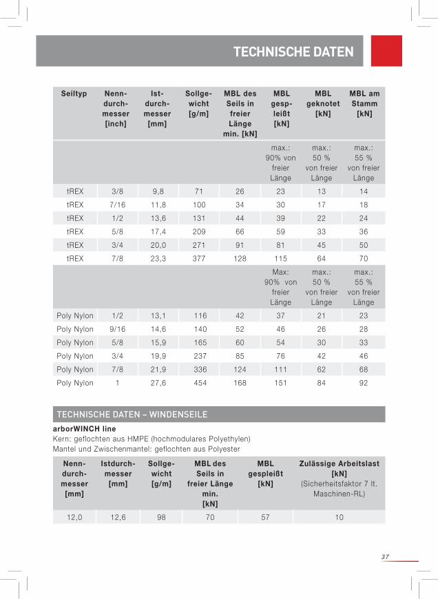
37
arborWINCH lineKern: geflochten aus HMPE (hochmodulares Polyethylen)Mantel und Zwischenmantel: geflochten aus Polyester
TECHNISCHE DATEN – WINDENSEILE
TECHNISCHE DATEN
Nenn-durch-messer
[mm]
Istdurch-messer
[mm]
Sollge-wicht [g/m]
MBL des Seils in
freier Länge min. [kN]
MBL gespleißt
[kN]
Zulässige Arbeitslast [kN]
(Sicherheitsfaktor 7 lt.Maschinen-RL)
12,0 12,6 98 70 57 10
max.: 90% von
freier Länge
max.: 50 %
von freier Länge
max.: 55 %
von freier Länge
tREX 3/8 9,8 71 26 23 13 14
tREX 7/16 11,8 100 34 30 17 18
tREX 1/2 13,6 131 44 39 22 24
tREX 5/8 17,4 209 66 59 33 36
tREX 3/4 20,0 271 91 81 45 50
tREX 7/8 23,3 377 128 115 64 70
Max: 90% von
freier Länge
max.: 50 %
von freier Länge
max.: 55 %
von freier Länge
Poly Nylon 1/2 13,1 116 42 37 21 23
Poly Nylon 9/16 14,6 140 52 46 26 28
Poly Nylon 5/8 15,9 165 60 54 30 33
Poly Nylon 3/4 19,9 237 85 76 42 46
Poly Nylon 7/8 21,9 336 124 111 62 68
Poly Nylon 1 27,6 454 168 151 84 92
Seiltyp Nenn-durch-messer [inch]
Ist-durch-messer
[mm]
Sollge-wicht [g/m]
MBL des Seils in freier Länge
min. [kN]
MBL gesp-leißt [kN]
MBL geknotet
[kN]
MBL am Stamm
[kN]
38
Beachten Sie die allgemeinen Vorbemerkungen zu technischen Daten, insbesondere was die statistische Relevanz betrifft!
Alle weiteren Werte wurden wie im folgenden Kapitel zu den technischen Werten beschrieben ermittelt. Sie sind nicht Teil unserer regelmäßigen Qualitätskontrolle. Verwenden Sie diese Daten als grobe Richtwerte, da sie nicht auf einer statistisch relevanten Stichproben-größe beruhen.
Die Angabe der MBL gespleißt gilt für den von TEUFELBERGER GesmbH ausgeführten Aug-spleiß. Der Spleiß wurde an einem Seilende ausgeführt. Je nach Ausführung des Spleißes kann der Verlust an MBL gegenüber der freien Länge bedeutend höher sein.
Die Loopie Schlingen wurden in zwei Anordnungen getestet, die sich in der Zugrichtung unter-scheiden. Sie werden in der Folge als „Zug in 0°“ (Abb. 4, Seite 12) und „Zug in 90°“ (Abb. 5, Seite 12) bezeichnet.
Die Soft Eye Schlingen wurden in zwei Anordnungen getestet, die sich in der Zugrichtung un-terscheiden. Sie werden in der Folge als „Zug in 90°“ (Abb. 6, Seite 12) und „Zug in 0°“ (Abb. 7, Seite 12) bezeichnet:
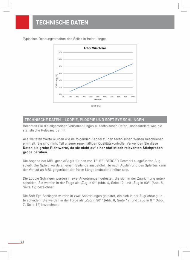
Typisches Dehnungverhalten des Seiles in freier Länge:
TECHNISCHE DATEN – LOOPIE, PLOOPIE UND SOFT EYE SCHLINGEN
TECHNISCHE DATEN
0%
2%
4%
6%
8%
10%
12%
0% 10% 20% 30% 40% 50% 60% 70% 80% 90% 100%
Elon
gatio
n [%
]
Force [%]
Arbor Winch line
Deh
nung
[%
]
Kraft [%]
39
tREXPolyesterhohlgeflecht mit gewachster Beschichtung
TECHNISCHE DATEN
Nenn- durch-messer[inch]
MBL des Seils in
freier Länge min. [kN]
Loopie Schlingein Zug 90°
[kN]
Loopie Schlingein Zug 0°
[kN]
Soft Eye Schlingein Zug 90°
[kN]
Soft Eye Schlingein Zug 0°
[kN]
max. 110 % von freier
Länge
max. 130 % von freier
Länge
max.: 55%von freier
Länge
max.: 65% von freier
Länge
3/8 26 28 33 14 16
7/16 34 37 44 18 22
1/2 44 48 57 24 28
5/8 66 72 85 36 42
3/4 91 100 118 50 59
7/8 128 140 166 70 83
Nenn-durch-messer [inch]
MBL des Seils in
freier Länge min. [kN]
Ploopie Schlingein Zug 90°
[kN]
Ploopie Schlingein Zug 0°
[kN]
max. 90 % von freier Länge
max. 110 % von freier Länge
7/16 34 30 37
1/2 44 39 48
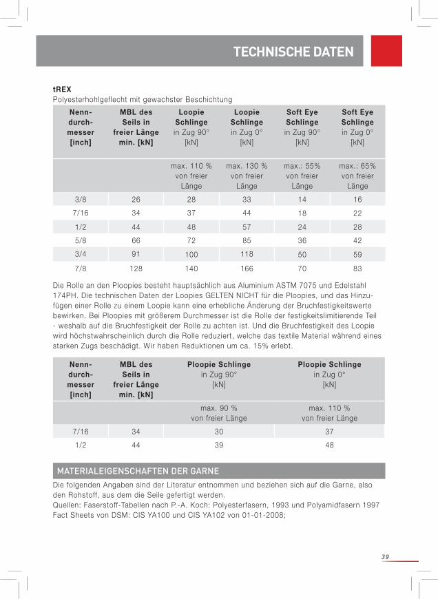
Die Rolle an den Ploopies besteht hauptsächlich aus Aluminium ASTM 7075 und Edelstahl 174PH. Die technischen Daten der Loopies GELTEN NICHT für die Ploopies, und das Hinzu-fügen einer Rolle zu einem Loopie kann eine erhebliche Änderung der Bruchfestigkeitswerte bewirken. Bei Ploopies mit größerem Durchmesser ist die Rolle der festigkeitslimitierende Teil - weshalb auf die Bruchfestigkeit der Rolle zu achten ist. Und die Bruchfestigkeit des Loopie wird höchstwahrscheinlich durch die Rolle reduziert, welche das texti le Material während eines starken Zugs beschädigt. Wir haben Reduktionen um ca. 15% erlebt.
MATERIALEIGENSCHAFTEN DER GARNEDie folgenden Angaben sind der Literatur entnommen und beziehen sich auf die Garne, also den Rohstoff, aus dem die Seile gefertigt werden. Quellen: Faserstoff-Tabellen nach P.-A. Koch: Polyesterfasern, 1993 und Polyamidfasern 1997Fact Sheets von DSM: CIS YA100 und CIS YA102 von 01-01-2008;
40
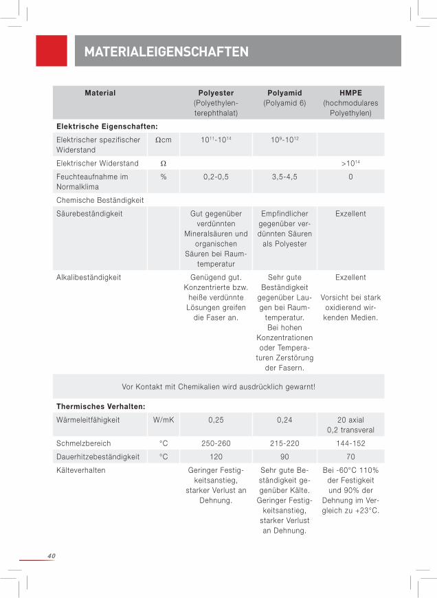
MATERIALEIGENSCHAFTEN
Material Polyester (Polyethylen-terephthalat)
Polyamid(Polyamid 6)
HMPE(hochmodulares
Polyethylen)
Elektrische Eigenschaften:
Elektrischer spezifischer Widerstand
Ωcm 1011-1014 109-1012
Elektrischer Widerstand Ω >1014
Feuchteaufnahme im Normalklima
% 0,2-0,5 3,5-4,5 0
Chemische Beständigkeit
Säurebeständigkeit Gut gegenüber verdünnten
Mineralsäuren und organischen
Säuren bei Raum-temperatur
Empfindlicher gegenüber ver-dünnten Säuren
als Polyester
Exzellent
Alkalibeständigkeit Genügend gut. Konzentrierte bzw.
heiße verdünnte Lösungen greifen
die Faser an.
Sehr gute Beständigkeit
gegenüber Lau-gen bei Raum-
temperatur.Bei hohen
Konzentrationen oder Tempera-
turen Zerstörung der Fasern.
Exzellent
Vorsicht bei stark oxidierend wir-
kenden Medien.
Vor Kontakt mit Chemikalien wird ausdrücklich gewarnt!
Thermisches Verhalten:
Wärmeleitfähigkeit W/mK 0,25 0,24 20 axial0,2 transveral
Schmelzbereich °C 250-260 215-220 144-152
Dauerhitzebeständigkeit °C 120 90 70
Kälteverhalten Geringer Festig-keitsanstieg,
starker Verlust an Dehnung.
Sehr gute Be-ständigkeit ge-genüber Kälte.
Geringer Festig-keitsanstieg,
starker Verlust an Dehnung.
Bei -60°C 110% der Festigkeit und 90% der
Dehnung im Ver-gleich zu +23°C.

41
Material Polyester (Polyethylen-terephthalat)
Polyamid(Polyamid 6)
HMPE(hochmodulares
Polyethylen)
Bewitterung Nach 1 Jahr Bewitterung noch 40-47% der Dop-pelbiegungen bis
zum Bruch.
Mäßige Stabil i-tät gegenüber
Lichteinwirkung.
Im Echttest (9 Monate im
Freien) ähnliche Restfestigkeit
wie bei Polyester (46%): 47%
Brennverhalten Brennt nicht fort, neigt aber zum
Abtropfen
Wie Polyester. Brennt aber
deutlich, wenn gefärbt oder imprägniert
Brennt nicht fort.
Entsorgung Hausmüll Hausmüll Hausmüll
MATERIALEIGENSCHAFTEN
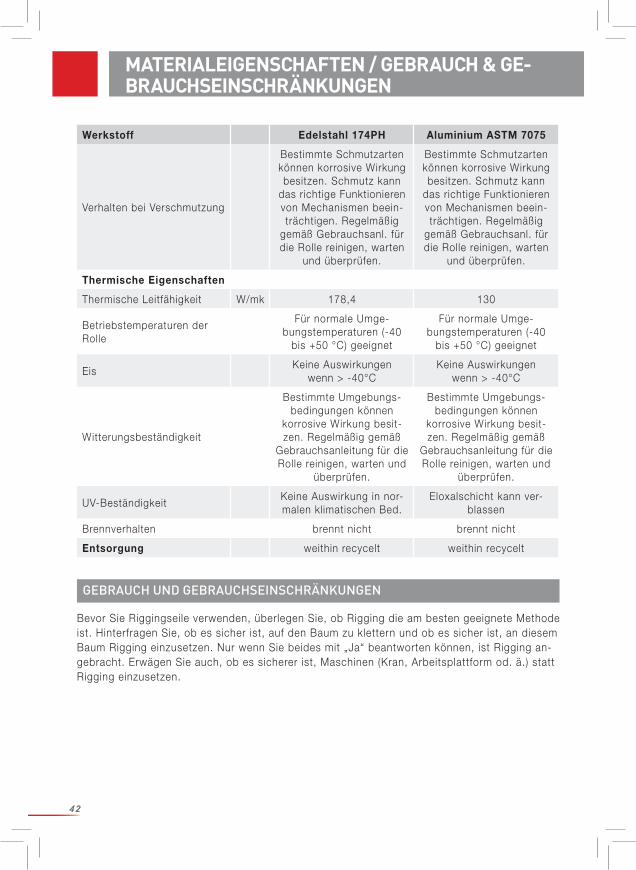
MATERIALEIGENSCHAFTEN VON METALLTEILENInformationen über Metallteile gehen u.a. auch aus den entsprechenden, dem Produkt beil ie-genden Benutzeranweisungen hervor.Einige Werte in der nachstehenden Tabelle stammen aus Materialdatenblättern und wurden nicht am eigentlichen Produkt gemessen. Bestimmte Faktoren können diese Werte beeinflussen (z.B. eine Eloxierungsschicht bewirkt eine drastische Reduktion der elektrischen Leitfähigkeit).
Werkstoff Edelstahl 174PH Aluminium ASTM 7075
Elektrische Eigenschaften
Spezifischer elektrischer Widerstand
Ωcm 8*106 5,15*106
(Eloxalschicht reduziert Leitfähigkeit)
Elektrischer Widerstand Ω
Feuchtigkeitsaufnahme % 0 0
Chemikalienbeständigkeit
Beständigkeit gegen SäurenStarke Säuren und Basen können korrosive Wirkung besitzen. Falls es zu einer Verschmutzung kommt, ist die Rolle entsprechend der Gebrauchsanleitung für die
Rolle zu reinigen und zu überprüfen.
Starke Säuren und Basen können korrosive Wirkung besitzen. Falls es zu einer Verschmutzung kommt, ist die Rolle entsprechend der Gebrauchsanleitung für die Rolle zu reinigen und zu überprüfen.
Beständigkeit gegen Basen
Kontakt mit Chemikalien vermeiden!
42
Werkstoff Edelstahl 174PH Aluminium ASTM 7075
Verhalten bei Verschmutzung
Bestimmte Schmutzarten können korrosive Wirkung besitzen. Schmutz kann
das richtige Funktionieren von Mechanismen beein-trächtigen. Regelmäßig
gemäß Gebrauchsanl. für die Rolle reinigen, warten
und überprüfen.
Bestimmte Schmutzarten können korrosive Wirkung besitzen. Schmutz kann
das richtige Funktionieren von Mechanismen beein-trächtigen. Regelmäßig
gemäß Gebrauchsanl. für die Rolle reinigen, warten
und überprüfen.
Thermische Eigenschaften
Thermische Leitfähigkeit W/mk 178,4 130
Betriebstemperaturen der Rolle
Für normale Umge-bungstemperaturen (-40
bis +50 °C) geeignet
Für normale Umge-bungstemperaturen (-40
bis +50 °C) geeignet
EisKeine Auswirkungen
wenn > -40°CKeine Auswirkungen
wenn > -40°C
Witterungsbeständigkeit
Bestimmte Umgebungs-bedingungen können
korrosive Wirkung besit-zen. Regelmäßig gemäß
Gebrauchsanleitung für die Rolle reinigen, warten und
überprüfen.
Bestimmte Umgebungs-bedingungen können
korrosive Wirkung besit-zen. Regelmäßig gemäß
Gebrauchsanleitung für die Rolle reinigen, warten und
überprüfen.
UV-BeständigkeitKeine Auswirkung in nor-malen klimatischen Bed.
Eloxalschicht kann ver-blassen
Brennverhalten brennt nicht brennt nicht
Entsorgung weithin recycelt weithin recycelt
GEBRAUCH UND GEBRAUCHSEINSCHRÄNKUNGEN
Bevor Sie Riggingseile verwenden, überlegen Sie, ob Rigging die am besten geeignete Methode ist. Hinterfragen Sie, ob es sicher ist, auf den Baum zu klettern und ob es sicher ist, an diesem Baum Rigging einzusetzen. Nur wenn Sie beides mit „Ja“ beantworten können, ist Rigging an-gebracht. Erwägen Sie auch, ob es sicherer ist, Maschinen (Kran, Arbeitsplattform od. ä.) statt Rigging einzusetzen.
MATERIALEIGENSCHAFTEN / GEBRAUCH & GE-BRAUCHSEINSCHRÄNKUNGEN
43
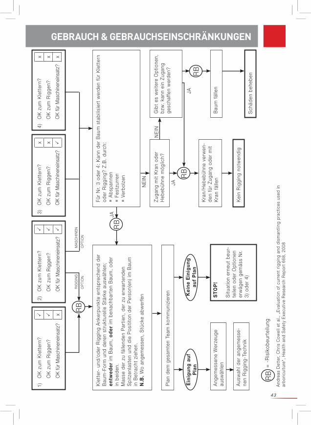
1)O
K z
um K
lett
ern?
OK
zum
Rig
gen?
OK
für M
asch
inen
eins
atz?
x
2)O
K z
um K
lett
ern?
OK
zum
Rig
gen?
OK
für M
asch
inen
eins
atz?
3)O
K z
um K
lett
ern?
x
OK
zum
Rig
gen?
x
OK
für M
asch
inen
eins
atz?
4)O
K z
um K
lett
ern?
x
OK
zum
Rig
gen?
x
OK
für M
asch
inen
eins
atz?
x
Kle
tter
- un
d/od
er R
iggi
ng A
nker
punk
te e
ntsp
rech
end
der
Bau
m-F
orm
und
der
en s
truk
ture
lle S
tärk
e au
swäh
len;
en
twed
er im
Bau
m,
od
er im
ben
achb
arte
n B
aum
, od
er
in b
eide
n.M
asse
der
zu
fälle
nden
Par
tien,
der
zu
erw
arte
nden
S
pitz
enla
sten
und
die
Pos
itito
n de
r P
erso
n(en
) im
Bau
m
in B
etra
cht
zieh
en.
N.B
. W
o an
gem
esse
n, S
tück
e ab
wer
fen
Für
Nr.
3 od
er 4
: K
ann
der
Bau
m s
tabi
lisie
rt w
erde
n fü
r K
lett
ern
oder
Rig
ging
? Z.
B.
durc
h:
Abs
pann
en
Fes
tzur
ren
V
erbo
lzen
Pla
n de
m g
esam
ten
Team
kom
mun
izie
ren
Zuga
ng m
it K
ran
oder
H
ebeb
ühne
mög
lich?
Gib
t es
wei
tere
Opt
ione
n,
bzw
. ka
nn e
in Z
ugan
g ge
scha
ffen
wer
den?
Kra
n/H
ebeb
ühne
ver
wen
-de
n fü
r Zu
gang
ode
r m
it K
ran
fälle
nB
aum
fäl
len
Kei
n R
iggi
ng n
otw
endi
g
Ang
emes
sene
Wer
zeug
e au
swäh
len
ST
OP
!
Situ
atio
n er
neut
beu
r -te
ilen
oder
Opt
ione
n er
wäg
en g
emäs
s N
r. 3)
ode
r 4)
Ein
igu
ng
au
f P
lan
Kei
ne
Ein
igu
ng
auf
Pla
n
RB
JA
JA
JA
NE
IN
NE
IN
MA
SC
HIN
EN
OP
TIO
N
RIG
GIN
G
OP
TIO
N
=
-R
isik
obeu
rtei
lung
Sch
äden
beh
eben
Aus
wah
l der
ang
emes
se-
nen
Rig
ging
-Tec
hnik
RB
RB
RB
RB
And
reas
Det
ter,
Chr
is C
owel
l et
al.,
„E
valu
atio
n of
cur
rent
rig
ging
and
dis
man
tling
pra
ctic
es u
sed
in
arbo
ricul
ture
“, H
ealth
and
Saf
ety
Exe
cutiv
e R
esea
rch
Rep
ort
668,
200
8
GEBRAUCH & GEBRAUCHSEINSCHRÄNKUNGEN
44
VOR DER VERWENDUNG ZU BEACHTEN
Bevor Sie Rigging-Arbeiten durchführen: Führen Sie eine genaue Risikoanalyse durch. Es ist die Verantwortung des Verwenders, dass eine relevante und „aktuelle“ Risikobewertung für die durchzuführenden Arbeiten vorliegt, die auch Notfälle mit einschließt. Insbesondere muss eine sorgfältige visuelle Baumkontrolle stattfinden. Planen und organisieren Sie sämtliche Schritte. Beachten Sie, dass sich einzelne Baum- stücke desselben Baumes in ihrem Verhalten unterscheiden. Demnach können für die verschiedenen Baumabschnitte auch verschiedene Maßnahmen und Techniken nötig sein. Rigging ist in der Regel Teamarbeit. Sorgen Sie dafür, dass jedes Teammitglied seinen Verantwortungsbereich kennt. Stellen Sie eine klare Kommunikation zwischen den Beteil- igten sicher durch Vereinbarung eindeutiger Sprach-/Handzeichen, evtl. auch durch den Einsatz von Funk od. ä.. Der Aufenthalt unter schwebender Last ist strengstens verboten (Lebensgefahr!). Dabei ist zu beachten, dass durch Wind die Fallkurve eines Baumabschnittes deutlich abgelenkt, der schwebende Baumabschnitt gedreht oder aus seiner axialen Richtung ausgelenkt werden kann. Der Freiraum ist entsprechend weiträumig abzusperren und der Zugang zu be- schränken, sodass niemand, speziell kein Passant, unbeabsichtigt den Gefahrenbereich betreten kann. Minimieren Sie Risiken und ergreifen Sie Maßnahmen, um Unfälle zu vermeiden. Ein Plan für Rettungsmaßnahmen, der alle denkbaren Notfälle berücksichtigt, muss vor Verwendung vorhanden sein. Vor und während des Gebrauchs ist zu überlegen, wie die Rettungsmaß- nahmen sicher und wirksam durchgeführt werden können. Die Situation jedes einzelnen Beteil igten ist dabei zu analysieren. Setzen Sie die Sicherheitsfaktoren fest. Wählen Sie die sicherste Rigging-Technik für Ihren Anwendungsfall! Wählen Sie dann das dafür passende Rigging-Equipment in der passenden Konfiguration. Ergreifen Sie alle Maßnahmen zur Sicherheit des Kletterers! Verwenden Sie die nötige persönliche Ausrüstung zum Schutz gegen Absturz (PSA)! Der Kletterer und seine PSA, also das System, durch das er gesichert wird, müssen sich außerhalb der Fallkurve, die das abzutragende Baumstück und das Riggingequipment beschreiben werden, befinden. Bitte halten Sie sich vor Augen, dass es bei einem Bruch des Seils zu einem starken Zurückschnellen des Seils mit im Baum hochschnellender Hard- ware kommen kann. Eine besonders kritische Situation entsteht, wenn das Baumstück gegen den Stamm prallt und den Baum in Schwingungen versetzt. Das Team muss die Auswirkung der entstehen- den Kräfte auf die Ankerstruktur, den/die Kletterer abschätzen und Maßnahmen ergreifen, um das Risiko auf ein akzeptables Maß zu senken. Der Kletterer muss eine Möglichkeit vorsehen, um den Baum vor der Schneide- und Riggingarbeit zu verlassen. Der Kletterer sollte eine Handsäge bei sich haben. Machen Sie sich die volle Verantwortung für die geplanten Arbeiten bewusst. Eine kompe- tente Person muss die Verantwortung für die Planung aller Riggingarbeiten übernehmen
SICHERHEITSHINWEISE
45
SICHERHEITSHINWEISE
Beachten Sie: Die Lasten, die beim Rigging auftreten können, sind nicht leicht zu quanti-fizieren und können sich dramatisch unterscheiden je nach Masse des Baumstückes, Rigging-Set-Up, Baumart, Zustand des Baumes und Form der Ankerstruktur. Lastspitzen können unbe-absichtigt auftreten, wenn beispielsweise das Bremsgerät blockiert. Sie können zum Versagen des Rigging-Equipment und / oder zum Abbrechen von Baum(teilen) führen. In der Literatur5 werden idealtypische Fallkurven beschrieben. Achtung! In der Praxis sind Ab-weichungen zu erwarten!
AUSWAHL DER AUSRÜSTUNG
Bevor Sie ein Riggingsystem aufbauen, führen Sie eine Risikoanalyse speziell für den geplanten Einsatzort durch. Legen Sie fest, wie die einzelnen Komponenten angeordnet werden. Stimmen Sie sämtliche Komponenten in ihrer Leistungsfähigkeit aufeinander ab. Ziehen Sie dazu die Belastbarkeit in der gewählten Konfiguration heran. Die visuelle Kontrolle des Baumes ist ein grundlegend wichtiger Arbeitsschritt. Überlegen Sie dabei, welche Belastungen beim Rigging im schlimmsten Fall auftreten können und ziehen sie unsichtbare Schäden am Baum im Erwägung.
Die technische Leistungsfähigkeit der trockenen Seile im Neuzustand unter Laborbedingungen ist im Kapitel „Technische Daten“ angegeben. Überlegen Sie, ob sie für Ihre Anwendung ausrei-chend ist.
5 Andreas Detter, Chris Cowell et al., „Evaluation of current rigging and dismantling practices used in arboriculture“, Health and Safety Executive Research Report 668, 2008
SICHERHEITSHINWEISE / AUSWAHL DER AUSRÜSTUNG
0,00,0
0,5 1,0
0,5
1,0
1,5
2,0
trajectory of centroid
vert
ikal
e Fa
llhöh
e in
[m
]
horizontaler Abstand in [m]
Baumstück kippt und beginnt zu fallen.
Eine Lastspitze tritt auf im Seilabschnitt, der am fallenden Baumstück befe-stigt ist.
46
Bedenken Sie dabei, dass dynamische Belastungen zu wesentlich höheren Kräften führen als statische, dass die Seilendverbindung eine geringere Bruchlast aufweist als das Seil in freier Länge. (Knoten senken die Bruchlast des Seiles erheblich - auch eine Reduktion um mehr als 50% ist möglich. Bei korrekt ausgeführten Spleißverbindungen ist von einer Reduktion in der Größenordnung von 10-20% auszugehen.) dass durch die Anordnung der Seile und Schlingen die auf sie wirkenden Kräfte deutlich beeinflusst werden dass Sie im Sinne der Sicherheit immer vom schlimmsten Fall („Worst- Case-Szenario“) ausgehen und unvorhergesehene Zwischenfälle berücksichtigen müssen.
Dynamische Belastungen erfolgen dann, wenn eine fallende/schwingende Last in das Rig-ging System stürzt. Je rascher oder abrupter die Last aufgefangen wird, umso größer fällt die dynamische Belastung aus. In derartigen Fällen kann die dynamische Last ohne weiteres ein Vielfaches der statischen Last erreichen. Ihre Arbeit soll so geplant sein, dass dynamische Lasten vermieden und/oder kontroll iert werden. Ziehen Sie die Tragfähigkeit der Ankerschlingen in Betracht, da die ausgeübten Kräfte mehr als das Doppelte der auf das Riggingseil wirkenden Kräfte sein können.
Eine kompetente Person, die in der Berechnung/Abschätzung der wirkenden Kräfte geschult ist und die Zusammenhänge mit der Masse des Baumstückes, mit Fallhöhe, Seiltype, Seil länge und anderen relevanten Größen kennt, muss am Einsatzort anwesend sein un die Riggingarbeiten managen.
Aus Untersuchungen6 geht hervor, dass die Belastung an der Ankerschlinge etwa 10-20 Mal so groß ist wie die Masse des Baumstücks. Achtung! Das ist nur ein grober Anhaltspunkt!
Vergewissern Sie sich, dass die Seileigenschaften für die jeweil ige Anwendung adäquat sind!
Wenden Sie einen entsprechenden Sicherheitsfaktor an. Entnehmen Sie bitte dem Merkblatt „International Guidelines on the Safer Use of Fiber Rope“ (CI 1401) des Tauwerk Instituts die Empfehlungen zur Wahl des Sicherheitsfaktors. Kostenlos abrufbar unter www.ropecord.com. Für Hebezwecke wird von der Maschinen-Richtlinie 2006/42/EG ein Sicherheitsfaktor von min-destens 7 (Verhältnis von Bruchlast des neuen unkonfektionierten Seiles zu statischer Arbeits-last) empfohlen. Die Literatur schlägt überdies vor, alle geschätzten Lasten mit einem Faktor von 1,5 zu multiplizieren7.
Beachten Sie, dass Ihr System nur so tragfähig ist wie die schwächste Komponente darin.
6 Brian Kane et al., „Forces and Stresses Generated During Rigging Operations“, Arboriculture & Forestry 2009, 35(2), 68-74. 7 Andreas Detter, Chris Cowell et al., „Evaluation of current rigging and dismantling practices used in arboriculture“, Health and Safety Executive Research Report 668, 2008
AUSWAHL DER AUSRÜSTUNG
47
INBETRIEBNAHME UND ANWENDUNG
AUSWAHL DER AUSRÜSTUNG
Abrollen einer Spule (Abb. 8, Seite 19)Wird das Seil von einer Spule abgenommen, sollte die Rolle selbst sich frei drehen können. Dies wirdermöglicht, indem Sie eine Stange durch die Mitte der Rolle schieben und das Seil abziehen, während die Spule sich dreht. Entfernen Sie niemals Seil von einer seitwärts l iegenden Rolle, da das Seil sich verdreht.
Abwickeln einer Trosse: Die Entfernung des Seils von einer Trosse sollte mit dem inneren Ende begonnen werden. Das Seil sollte gegen den Uhrzeigersinn abgewickelt werden. Wird das Seil im Uhrzeigersinn abge-zogen, entstehen Knoten. In diesem Fall wickeln Sie das Seil zurück, wenden die Trosse und ziehen wieder von der Mitte. Nun sollte das Seil gegen den Uhrzeigersinn und knotenfrei laufen.
Knoten: Beachten Sie, dass jeder Knoten die Bruchkraft deutlich reduziert. In unseren Messungen wurde der Doppel-Palstek verwendet.
Anleitung für den Doppel-Palstek siehe Abbildungen 9 - 13, Seite 20)
Spleiß: Beachten Sie, dass jeder Spleiß die Bruchkraft reduziert. Fertigen Sie nur dann selbst einen Spleiß an, wenn Sie darin geschult sind! Spleißanleitungen für Sirius, Poly Nylon, Sta Set, arborWINCH line und tRex stehen auf unserer Homepage www.teufelberger.com zum Download zur Verfügung.Wir übernehmen keinerlei Haftung für Spleiße oder sonstige Konfektionierung an Seilen, die nicht von TEUFELBERGER ausgeführt worden sind.
Loopie Sling:Install ieren Sie den Pulley auf der Loopie Sling und streifen Sie den Spleiß sorgfältig aus. (Abb. 14 - 15, Seite 20)
Umschlingen Sie den Baum und ziehen Sie den Pulley durch die Loopie Sling. Die Loopie Sling kann in Ihrer Länge eingestellt werden: Ziehen Sie die Schlinge eng zusammen und prüfen Sie, dass Schlinge und Rolle einen guten Halt haben. (Abb. 16 - 18, Seite 21)
Soft Eye Sling: Legen Sie wie in der folgenden Bildern dargestellt das Auge mit dem Pulley um den Baum. Das versteifte Seilende wirkt als Einfädelhilfe. (Abb. 19 - 24, Seite 21)
Stecken Sie das lose Ende zwischen Schlinge und Baum fest. (Abb. 25, Seite 22)
Montieren Sie nun das Arbeitsseil mit einem Doppelpalstek wie im Kapitel über technische Daten genauer ausgeführt. (Abb. 26 - 29, Seite 22)
INBETRIEBNAHME UND ANWENDUNG
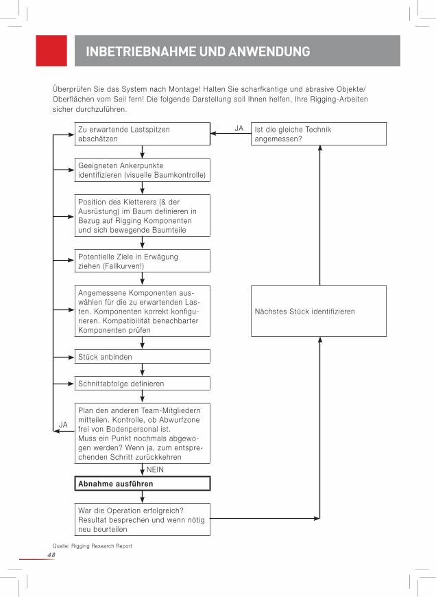
48
Zu erwartende Lastspitzen abschätzen
Ist die gleiche Technik angemessen?
Geeigneten Ankerpunkte identif izieren (visuelle Baumkontrolle)
Position des Kletterers (& der Ausrüstung) im Baum definieren in Bezug auf Rigging Komponenten und sich bewegende Baumteile
Potentielle Ziele in Erwägung ziehen (Fallkurven!)
Angemessene Komponenten aus-wählen für die zu erwartenden Las-ten. Komponenten korrekt konfigu-rieren. Kompatibil ität benachbarter Komponenten prüfen
Nächstes Stück identif izieren
Stück anbinden
Schnittabfolge definieren
Plan den anderen Team-Mitgliedern mitteilen. Kontrolle, ob Abwurfzone frei von Bodenpersonal ist.Muss ein Punkt nochmals abgewo-gen werden? Wenn ja, zum entspre-chenden Schritt zurückkehren
Abnahme ausführen
War die Operation erfolgreich? Resultat besprechen und wenn nötig neu beurteilen
JA
JA
NEIN
INBETRIEBNAHME UND ANWENDUNG
Quelle: Rigging Research Report
Überprüfen Sie das System nach Montage! Halten Sie scharfkantige und abrasive Objekte/Oberflächen vom Seil fern! Die folgende Darstellung soll Ihnen helfen, Ihre Rigging-Arbeiten sicher durchzuführen.
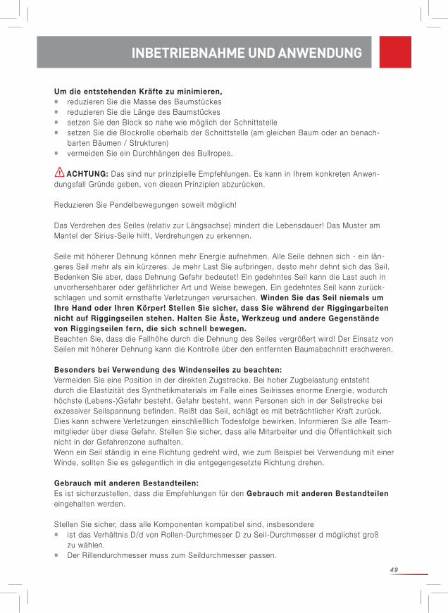
49
INBETRIEBNAHME UND ANWENDUNG
Um die entstehenden Kräfte zu minimieren, reduzieren Sie die Masse des Baumstückes reduzieren Sie die Länge des Baumstückes setzen Sie den Block so nahe wie möglich der Schnittstelle setzen Sie die Blockrolle oberhalb der Schnittstelle (am gleichen Baum oder an benach- barten Bäumen / Strukturen) vermeiden Sie ein Durchhängen des Bullropes.
ACHTUNG: Das sind nur prinzipielle Empfehlungen. Es kann in Ihrem konkreten Anwen-dungsfall Gründe geben, von diesen Prinzipien abzurücken.
Reduzieren Sie Pendelbewegungen soweit möglich!
Das Verdrehen des Seiles (relativ zur Längsachse) mindert die Lebensdauer! Das Muster am Mantel der Sirius-Seile hilft, Verdrehungen zu erkennen.
Seile mit höherer Dehnung können mehr Energie aufnehmen. Alle Seile dehnen sich - ein län-geres Seil mehr als ein kürzeres. Je mehr Last Sie aufbringen, desto mehr dehnt sich das Seil.Bedenken Sie aber, dass Dehnung Gefahr bedeutet! Ein gedehntes Seil kann die Last auch in unvorhersehbarer oder gefährlicher Art und Weise bewegen. Ein gedehntes Seil kann zurück-schlagen und somit ernsthafte Verletzungen verursachen. Winden Sie das Seil niemals um Ihre Hand oder Ihren Körper! Stellen Sie sicher, dass Sie während der Riggingarbeiten nicht auf Riggingseilen stehen. Halten Sie Äste, Werkzeug und andere Gegenstände von Riggingseilen fern, die sich schnell bewegen. Beachten Sie, dass die Fallhöhe durch die Dehnung des Seiles vergrößert wird! Der Einsatz von Seilen mit höherer Dehnung kann die Kontrolle über den entfernten Baumabschnitt erschweren.
Besonders bei Verwendung des Windenseiles zu beachten: Vermeiden Sie eine Position in der direkten Zugstrecke. Bei hoher Zugbelastung entsteht durch die Elastizität des Synthetikmaterials im Falle eines Seilrisses enorme Energie, wodurch höchste (Lebens-)Gefahr besteht. Gefahr besteht, wenn Personen sich in der Seilstrecke bei exzessiver Seilspannung befinden. Reißt das Seil, schlägt es mit beträchtlicher Kraft zurück. Dies kann schwere Verletzungen einschließlich Todesfolge bewirken. Informieren Sie alle Team-mitglieder über diese Gefahr. Stellen Sie sicher, dass alle Mitarbeiter und die Öffentlichkeit sich nicht in der Gefahrenzone aufhalten. Wenn ein Seil ständig in eine Richtung gedreht wird, wie zum Beispiel bei Verwendung mit einer Winde, sollten Sie es gelegentlich in die entgegengesetzte Richtung drehen.
Gebrauch mit anderen Bestandteilen:Es ist sicherzustellen, dass die Empfehlungen für den Gebrauch mit anderen Bestandteilen eingehalten werden.
Stellen Sie sicher, dass alle Komponenten kompatibel sind, insbesondere ist das Verhältnis D/d von Rollen-Durchmesser D zu Seil-Durchmesser d möglichst groß zu wählen. Der Ril lendurchmesser muss zum Seildurchmesser passen.
INBETRIEBNAHME UND ANWENDUNG
50
REGELMÄSSIGE ÜBERPRÜFUNG
WARNUNG - SICHERHEITSHINWEISE
Generell gilt: Wenn sich der Anwender aus irgendeinem - im ersten Moment auch noch so unbedeutenden - Grund nicht sicher ist, dass das Produkt entspricht, ist es aus dem Verkehr zu nehmen und unbrauchbar zu machen oder zu isolieren und deutlich sichtbar zu kennzeichnen, sodass es nicht versehentlich verwendet werden kann. Es darf erst dann wieder benutzt werden, wenn es von einer sachkundigen Person geprüft und schriftl ich freigegeben worden ist.
Nach einer heftigen Stoßbelastung kann es nötig sein, das Seil auszutauschen. Die Fähigkeit des Seiles, dynamische Belastungen zu dämpfen, nimmt durch normalen Einsatz und Stoßbelastungen ab. Ein gebrauchtes Seil ist nicht mehr so dehnbar wie ein neues und kann daher auch nicht so viel Energie aufnehmen, die Spitzenlast steigt. Gleichzeitig sinkt die Bruchlast des Seiles.
Prüfen Sie das Produkt vor und nach jedem Einsatz wie folgend beschrieben:Vor jedem und nach jeder Benützung ist das Produkt einer Sicht- und Tastprüfung zu unter-ziehen, um Vollständigkeit, gebrauchsfähigen Zustand und das richtige Funktionieren sicherzu-stellen. Betrachten Sie das Seil von allen Seiten und über seine gesamte Länge. Tasten Sie auch ein augenscheinlich intaktes Seil auf verborgene Schäden des Kerns ab, die etwa durch häufiges Biegen oder lokales Überlasten verursacht werden können. Achten Sie auf Stellen, die ther-misch geschädigt sind (glasartige Seiloberfläche), was durch hohe Reibung im System verur-sacht werden kann. Achten Sie besonders auf den Seilabschnitt, der in dem Halbschlag an dem Baumstamm verwendet wird. Dieser Teil des Seils ist für gewöhnlich der am stärksten beschädigte. Es kann erforderlich sein, diesen Teil des Seils abzuschneiden und einen neuen Spleiß anzufertigen oder das andere Seilende zu verwenden. Im Zweifelsfall ist das Produkt auszuscheiden!
Die Sirius Bullropes sind mit Querstreifen in regelmäßigen Abständen ausgestattet. Wenn sich dieser Abstand verändert ( in der Regel vergrößert), ist das ein Zeichen für eine lokale Über-lastung. Das Seilstück darf nicht mehr verwendet werden.
Von der Verwendung von Seilen mit Abnutzungserscheinungen wird dringend abgera-ten. Verwenden Sie ausschließlich einwandfreie Seile, die keine Schnitte, Knoten oder abgeris-sene Stränge aufweisen. Vermeiden Sie Abrieb des Seils durch Scheuern an rauen Oberflächen. Achten Sie auf gleichmäßige Abnutzung. Knoten Sie ein gerissenes Seil keinesfalls an sondern scheiden Sie es aus!
REGELMÄSSIGE ÜBERPRÜFUNG
Stellen Sie sicher, dass alle Komponenten korrekt angeordnet sind.
Wird dies verabsäumt, so erhöht sich das Risiko von schweren oder tödlichen Verletzungen.

51
Wir empfehlen, über Verwendung (Datum, Dauer, Bedingungen) und Überprüfung (Datum, Prü-fer, Auffäll igkeiten) Aufzeichnungen zu führen. Beachten Sie, dass auch nationale Regelwerke für Prüfungsintervalle ggf. anzuwenden sind.
Kontroll ieren Sie immer das gesamte Seil inklusive Endverbindungen und Hardware! Bei geringsten Unsicherheiten ist das Produkt auszuscheiden bzw. durch einen Sach-kundigen zu prüfen.
Checkliste: Die Prüfung muss beinhalten: Kontrolle des Allgemeinzustandes: Alter, Vollständigkeit, Verschmutzung, richtige Zusammensetzung. Kontrolle der Etikette: Etikette vorhanden und lesbar ja/nein, Herstell jahr ersichtlich. Kontrolle aller Einzelteile auf mechanische Beschädigung wie: Schnitte, Risse, Kerben, Abscheuerungen, Deformation, Rippenbildung, Krangel / nicht auflösbare Verdrehungen, Quetschungen, Dickstellen. Kontrolle aller Einzelteile auf thermische oder chemische Beschädigungen wie: Verschmelzungen, Verhärtungen, Versteifungen, Verfärbungen. Kontrolle metall ischer Teile auf Korrosion und Deformationen. Kontrolle des Zustands und der Vollständigkeit der Endverbindungen, Nähte (z.B. kein Abscheuern des Nähgarnes), Spleiße (z.B. kein Auseinanderrutschen), Knoten vorhanden.
Die regelmäßige Überprüfung der Ausrüstung ist unbedingt notwendig. Ihre Sicherheit hängt von der Wirksamkeit und Haltbarkeit der Ausrüstung ab!
Für weitere Informationen verweisen wir Sie auf das Merkblatt CI 2001 — Fiber Rope Inspec-tion and Retirement Criteria - des Tauwerk Instituts. Abrufbar unter www.ropecord.com.
Instandsetzungen dürfen nur vom Hersteller durchgeführt werden.
Nur bei seltenem Gebrauch (1 Woche pro Jahr) und ordnungsgemäßer Lagerung (sieheTransport, Lagerung und Reinigung) kann die Verwendungsdauer bis zu 5 Jahren ab Herstell-datum betragen. Das Herstell jahr kann an der Etikette abgelesen werden. Kann das Alter des Produktes nicht zweifelsfrei festgestellt werden, ist es aus dem Verkehr zu nehmen.
Die tatsächliche Lebensdauer ist ausschließlich vom Zustand des Produktes abhängig,der von zahlreichen Faktoren (s.o.) beeinflusst wird. Sie kann sich durch extreme Einflüsse auf eine einzige Verwendung verkürzen oder noch weniger, wenn die Ausrüstung noch vor dem ersten Gebrauch (z.B. Transport) beschädigt wird.
Mechanische Abnutzung oder andere Einflüsse wie z.B. die Einwirkung von Sonnenlicht reduzieren die Lebensdauer stark. Ausgebleichte oder aufgescheuerte Fasern / Gurtbänder, Verfärbungen und Verhärtungen sind ein sicheres Zeichen, dass das Produkt aus dem Verkehr
INSTANDHALTUNG
LEBENSDAUER
INSTANDHALTUNG / LEBENSDAUER

52
Der Transport soll immer l icht- und schmutzgeschützt und mit geeigneter Verpackung (feuch-tigkeitsabweisendes, l ichtundurchlässiges Material) erfolgen.
Lagerbedingungen: geschützt von UV-Strahlung (Sonnenlicht, Schweißgeräte..), trocken und sauber bei Raumtemperatur (15 – 25°C), fern von Chemikalien (Säuren, Laugen, Flüssigkeiten, Dämpfe, Gase...) und anderen aggressiven Bedingungen, geschützt von scharfkantigen Gegenständen
Lagern Sie das Produkt deshalb trocken und belüftet in einem feuchtigkeitsabweisenden Sack, der l ichtundurchlässig ist. Vermeiden Sie dabei Verdrehungen des Seils!Achten Sie auf die Sauberkeit des Produktes! Eingeriebener Schmutz schädigt das Seil. Feuch-te, verschmutzte Seile können faulen.
Zur Reinigung verwenden Sie lauwarmes Wasser und Feinwaschmittel. Anschließend ist die Ausrüstung mit klarem Wasser auszuspülen und vor der Lagerung zu trocknen. Das Produkt ist auf natürliche Weise zu trocknen, nicht in der Nähe von Feuer oder anderen Hitzequellen.
Zur Desinfektion dürfen nur Stoffe verwendet werden, die keinen Einfluss auf die verwendeten Synthetikmaterialien haben.
Bei Nicht-Einhaltung gefährden Sie sich selbst!
TRANSPORT, LAGERUNG UND REINIGUNG
TRANSPORT, LAGERUNG UND REINIGUNG
zu ziehen ist.
Eine allgemeingültige Aussage über die Lebensdauer des Produktes kann ausdrücklich nicht gemacht werden, da sie von verschiedenen Faktoren, wie z.B. UV-Licht, Art und Häufigkeit des Gebrauches, Behandlung, Witterungseinflüssen wie Eis oder Schnee, Umgebung wie Salz, Sand, Batteriesäure usw., Hitzebelastung (über normale klimatische Bedingungen hinaus), me-chanische Verformung und / oder Verbeulung abhängt.
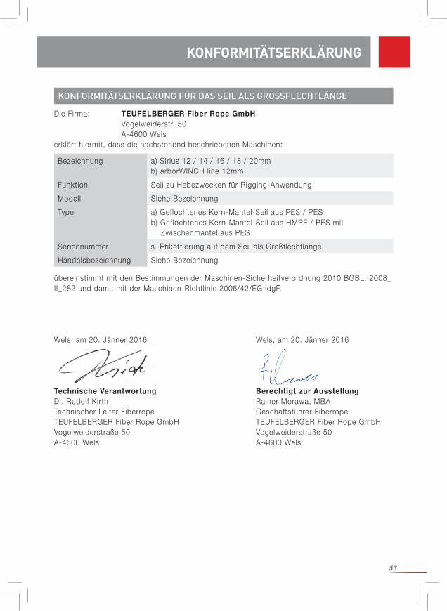
53
KONFORMITÄTSERKLÄRUNG FÜR DAS SEIL ALS GROSSFLECHTLÄNGE
Bezeichnung a) Sirius 12 / 14 / 16 / 18 / 20mmb) arborWINCH line 12mm
Funktion Seil zu Hebezwecken für Rigging-Anwendung
Modell Siehe Bezeichnung
Type a) Geflochtenes Kern-Mantel-Seil aus PES / PESb) Geflochtenes Kern-Mantel-Seil aus HMPE / PES mit Zwischenmantel aus PES.
Seriennummer s. Etikettierung auf dem Seil als Großflechtlänge
Handelsbezeichnung Siehe Bezeichnung
Die Firma: TEUFELBERGER Fiber Rope GmbH Vogelweiderstr. 50 A-4600 Welserklärt hiermit, dass die nachstehend beschriebenen Maschinen:
übereinstimmt mit den Bestimmungen der Maschinen-Sicherheitverordnung 2010 BGBL. 2008_II_282 und damit mit der Maschinen-Richtlinie 2006/42/EG idgF.
Wels, am 20. Jänner 2016 Wels, am 20. Jänner 2016
Technische Verantwortung Berechtigt zur Ausstellung DI. Rudolf Kirth Rainer Morawa, MBATechnischer Leiter Fiberrope Geschäftsführer FiberropeTEUFELBERGER Fiber Rope GmbH TEUFELBERGER Fiber Rope GmbHVogelweiderstraße 50 Vogelweiderstraße 50A-4600 Wels A-4600 Wels
KONFORMITÄTSERKLÄRUNG
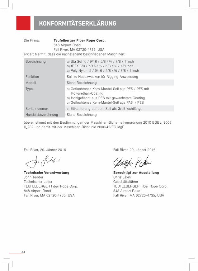
54
Bezeichnung a) Sta Set ½ / 9/16 / 5/8 / ¾ / 7/8 / 1 inchb) tREX 3/8 / 7/16 / ½ / 5/8 / ¾ / 7/8 inchc) Poly Nylon ½ / 9/16 / 5/8 / ¾ / 7/8 / 1 inch
Funktion Seil zu Hebezwecken für Rigging-Anwendung
Modell Siehe Bezeichnung
Type a) Geflochtenes Kern-Mantel-Seil aus PES / PES mit Polyurethan-Coating b) Hohlgeflecht aus PES mit gewachstem Coating c) Geflochtenes Kern-Mantel-Seil aus PA6 / PES
Seriennummer s. Etikettierung auf dem Seil als Großflechtlänge
Handelsbezeichnung Siehe Bezeichnung
Die Firma: Teufelberger Fiber Rope Corp. 848 Airport Road Fall River, MA 02720-4735, USAerklärt hiermit, dass die nachstehend beschriebenen Maschinen:
übereinstimmt mit den Bestimmungen der Maschinen-Sicherheitverordnung 2010 BGBL. 2008_II_282 und damit mit der Maschinen-Richtlinie 2006/42/EG idgF.
Fall River, 20. Jänner 2016 Fall River, 20. Jänner 2016
Technische Verantwortung Berechtigt zur Ausstellung John Tedder Chris LavinTechnischer Leiter GeschäftsführerTEUFELBERGER Fiber Rope Corp. TEUFELBERGER Fiber Rope Corp.848 Airport Road 848 Airport RoadFall River, MA 02720-4735, USA Fall River, MA 02720-4735, USA
KONFORMITÄTSERKLÄRUNG
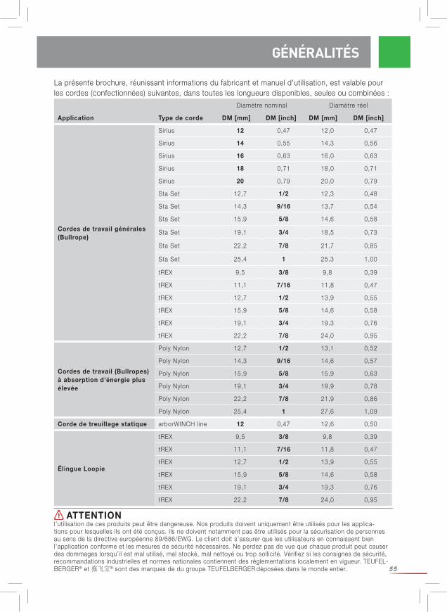
55
La présente brochure, réunissant informations du fabricant et manuel d'utilisation, est valable pour les cordes (confectionnées) suivantes, dans toutes les longueurs disponibles, seules ou combinées :
GÉNÉRALITÉS
ATTENTIONl’utilisation de ces produits peut être dangereuse. Nos produits doivent uniquement être utilisés pour les applica-tions pour lesquelles ils ont été conçus. Ils ne doivent notamment pas être utilisés pour la sécurisation de personnes au sens de la directive européenne 89/686/EWG. Le client doit s’assurer que les utilisateurs en connaissent bien l’application conforme et les mesures de sécurité nécessaires. Ne perdez pas de vue que chaque produit peut causer des dommages lorsqu’il est mal utilisé, mal stocké, mal nettoyé ou trop sollicité. Vérifiez si les consignes de sécurité, recommandations industrielles et normes nationales contiennent des réglementations localement en vigueur. TEUFEL-BERGER® et 拖飞宝® sont des marques de du groupe TEUFELBERGER déposées dans le monde entier.
Diamètre nominal Diamètre réel
Application Type de corde DM [mm] DM [inch] DM [mm] DM [inch]
Cordes de travail générales(Bullrope)
Sirius 12 0,47 12,0 0,47
Sirius 14 0,55 14,3 0,56
Sirius 16 0,63 16,0 0,63
Sirius 18 0,71 18,0 0,71
Sirius 20 0,79 20,0 0,79
Sta Set 12,7 1/2 12,3 0,48
Sta Set 14,3 9/16 13,7 0,54
Sta Set 15,9 5/8 14,6 0,58
Sta Set 19,1 3/4 18,5 0,73
Sta Set 22,2 7/8 21,7 0,85
Sta Set 25,4 1 25,3 1,00
tREX 9,5 3/8 9,8 0,39
tREX 11,1 7/16 11,8 0,47
tREX 12,7 1/2 13,9 0,55
tREX 15,9 5/8 14,6 0,58
tREX 19,1 3/4 19,3 0,76
tREX 22,2 7/8 24,0 0,95
Cordes de travail (Bullropes) à absorption d'énergie plus élevée
Poly Nylon 12,7 1/2 13,1 0,52
Poly Nylon 14,3 9/16 14,6 0,57
Poly Nylon 15,9 5/8 15,9 0,63
Poly Nylon 19,1 3/4 19,9 0,78
Poly Nylon 22,2 7/8 21,9 0,86
Poly Nylon 25,4 1 27,6 1,09
Corde de treuillage statique arborWINCH line 12 0,47 12,6 0,50
Élingue Loopie
tREX 9,5 3/8 9,8 0,39
tREX 11,1 7/16 11,8 0,47
tREX 12,7 1/2 13,9 0,55
tREX 15,9 5/8 14,6 0,58
tREX 19,1 3/4 19,3 0,76
tREX 22,2 7/8 24,0 0,95
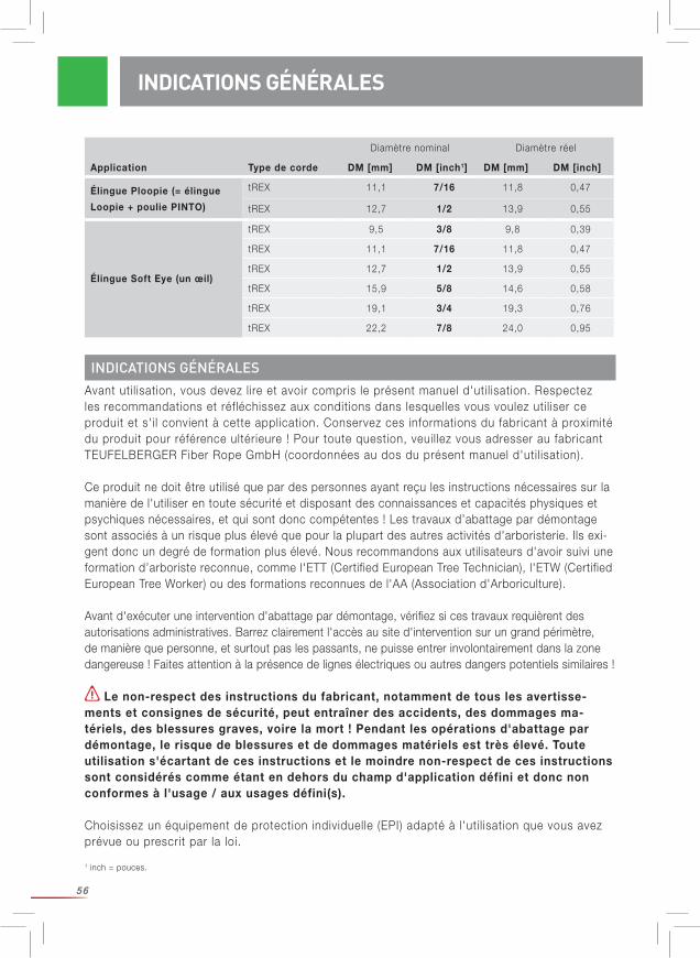
56
Avant uti l isation, vous devez lire et avoir compris le présent manuel d'uti l isation. Respectez les recommandations et réfléchissez aux conditions dans lesquelles vous voulez uti l iser ce produit et s'i l convient à cette application. Conservez ces informations du fabricant à proximité du produit pour référence ultérieure ! Pour toute question, veuil lez vous adresser au fabricant TEUFELBERGER Fiber Rope GmbH (coordonnées au dos du présent manuel d'uti l isation).
Ce produit ne doit être utilisé que par des personnes ayant reçu les instructions nécessaires sur la manière de l'utiliser en toute sécurité et disposant des connaissances et capacités physiques et psychiques nécessaires, et qui sont donc compétentes ! Les travaux d’abattage par démontage sont associés à un risque plus élevé que pour la plupart des autres activités d'arboristerie. Ils exi-gent donc un degré de formation plus élevé. Nous recommandons aux utilisateurs d'avoir suivi une formation d’arboriste reconnue, comme l'ETT (Certified European Tree Technician), l'ETW (Certified European Tree Worker) ou des formations reconnues de l'AA (Association d'Arboriculture).
Avant d'exécuter une intervention d'abattage par démontage, vérifiez si ces travaux requièrent des autorisations administratives. Barrez clairement l'accès au site d'intervention sur un grand périmètre, de manière que personne, et surtout pas les passants, ne puisse entrer involontairement dans la zone dangereuse ! Faites attention à la présence de lignes électriques ou autres dangers potentiels similaires !
Le non-respect des instructions du fabricant, notamment de tous les avertisse-ments et consignes de sécurité, peut entraîner des accidents, des dommages ma-tériels, des blessures graves, voire la mort ! Pendant les opérations d'abattage par démontage, le risque de blessures et de dommages matériels est très élevé. Toute utilisation s'écartant de ces instructions et le moindre non-respect de ces instructions sont considérés comme étant en dehors du champ d'application défini et donc non conformes à l'usage / aux usages défini(s).
Choisissez un équipement de protection individuelle (EPI) adapté à l'uti l isation que vous avez prévue ou prescrit par la loi.
INDICATIONS GÉNÉRALES
INDICATIONS GÉNÉRALES
Élingue Soft Eye (un œil)
tREX 9,5 3/8 9,8 0,39
tREX 11,1 7/16 11,8 0,47
tREX 12,7 1/2 13,9 0,55
tREX 15,9 5/8 14,6 0,58
tREX 19,1 3/4 19,3 0,76
tREX 22,2 7/8 24,0 0,95
Diamètre nominal Diamètre réel
Application Type de corde DM [mm] DM [inch1] DM [mm] DM [inch]
Élingue Ploopie (= élingue
Loopie + poulie PINTO)
tREX 11,1 7/16 11,8 0,47
tREX 12,7 1/2 13,9 0,55
1 inch = pouces.
57
UTILISATION CONFORME À LA DESTINATION
Respectez les consignes de sécurité (nationales) touchant à l'abattage par démon-tage et au choix de l'EPI !
Nous considérons ce manuel d'utilisation comme étant un « work in progress », en cours de réa-lisation. Sur notre site, nous avons simulé des charges dynamiques et allons poursuivre ce travail par des mesures des données dynamiques. Les résultats recueillis seront publiés sur notre page d'accueil www.teufelberger.com.
Le démontage est l'opération consistant à abattre un arbre par parties successives à l'aide d'un système de levage étudié, composé de cordes textiles, de poulies et (en règle générale) du tronc de l'arbre qui sert de structure d'appui naturelle. Ce système est réalisé de manière à résister aux forces importantes qui surviennent au moment d'amortir la chute des tronçons d'arbre.
La corde (confectionnée) qu'accompagnent les présentes informations du fabricant, est exclu-sivement destinée à être uti l isée comme composant d'un systèmes pour travaux d'abattage par démontage. I l est de la responsabil ité de l'uti l isateur de s'assurer de la compatibil ité de chaque composant d'un produit avec les composants avoisinants.
À prendre en compte : « Les différents composants du système interagissent les uns avec les autres. Cette interaction n'a pas encore été analysée et comprise dans son intégralité. Lors de l'abattage par démontage, le grimpeur, l'équipement et l'arbre lui-même sont soumis à des soll icitations importantes qu'il est diff ici le de calculer. »2 C'est à l'uti l isateur qu'il revient d'évaluer le risque que cela représente et de le minimiser.
TEUFELBERGER n'est pas responsable de conséquences / dommages directs, indirects ou fortuits survenant pendant ou après l'uti l isation du produit et résultant d'une util isation non conforme à la destination, incluant une modification des cordages (réalisation d'un œillet, etc.), une combinaison erronée avec d'autres composants ou une disposition mal choisie.
Les produits d'abattage par démontage ne doivent pas être uti l isés comme équipement de protection individuelle (EPI).
I l est important de marquer les équipements de démontage de manière à exclure toute con-fusion avec les EPI et toute possibil ité de les uti l iser comme tels. Conservez les cordes de démontage séparément des autres équipements de grimpe.
Fabricant : TEUFELBERGER Fiber Rope GmbH, Vogelweiderstr. 50, A-4600 WelsType Indique le type d'uti l isation autorisé (cf. Tableau 1)Sirius etc. Désignation de la corde
UTILISATION / EXPLICATION DU MARQUAGE
EXPLICATION DU MARQUAGE
2 Tiré de : Andreas Detter, Rigging-Techniken beim Abtragen von Bäumen. Teil 1: Kinematische Analysen, AFZ-Der Wald 24/2008, p. 1322s.
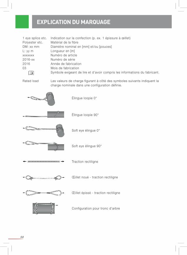
58
EXPLICATION DU MARQUAGE
1 eye splice etc. Indication sur la confection (p. ex. 1 épissure à œillet)Polyester etc. Matérial de la fibreDM: xx mm Diamètre nominal en [mm] et/ou [pouces]L: yy m Longueur en [m]xxxxxxx Numéro de article2016-xx Numéro de série2016 Année de fabrication03 Mois de fabrication Symbole exigeant de lire et d'avoir compris les informations du fabricant.
Rated load Les valeurs de charge figurant à côté des symboles suivants indiquent la charge nominale dans une configuration définie.
Élingue loopie 0°
Élingue loopie 90°
Soft eye élingue 0°
Soft eye élingue 90°
Traction rectil igne
Œillet noué - traction rectil igne
Œillet épissé - traction rectil igne
Configuration pour tronc d'arbre
59
3 CRM = charge de rupture minimale,
DONNÉES TECHNIQUES
L'ensemble des données ci-dessous s'applique à des cordes neuves et sèches dans des conditions de laboratoire. Toutes les indications sur la charge de rupture sont valables pour des conditions statiques.
Util iser les cordes revient à en modifier les caractéristiques : leur capacité d'allongement dimi-nue, leur force de rupture diminue.
Lors d'une util isation pour un démontage, i l est nécessaire de tenir compte des intempéries : en règle générale, l'humidité réduit la force de rupture et augmente l'allongement de la corde en charge. Les cordes mouil lées peuvent notamment se contracter. De même, des températures élevées ou basses (en été ou en hiver) influent sur la force de rupture de la corde. I l en va de même pour l'encrassement de la corde, l' influence de la lumière solaire etc. Vous devez toujours partir du principe que la force de rupture va diminuer ! Notez que les cordes se raidissent en cas de gel et que leur comportement se modifie en conséquence !
Les sécrétions des arbres (p. ex. : résines, exsudats collants etc.) peuvent créer des conditions similaires à celles provoquées par des colles ou des lubrif iants, si bien que le comportement des cordes sur des poulies, au niveau des nœuds etc. peut être nettement modifié.
Nous testons régulièrement la CRM3 en longueur l ibre de nos cordes (neuves, sèches, condi-tions de laboratoire).
Les données supplémentaires figurant ci-dessous ont été obtenues comme décrit dans les chapitres suivants concernant les données techniques. Elles ne font pas partie de notre contrôle de qualité régulier. Les valeurs « CRM épissurée » sont uniquement valables pour l'épissure à œillet fabriquée par TEUFELBERGER. Seule une extrémité de la corde était pour-vue d'une épissure. En fonction de l'exécution de l'épissure, les pertes de CRM peuvent con-sidérablement varier par rapport à la valeur pour la « longueur l ibre ». Considérez ces données comme des valeurs approximatives, car elles ne s'appuient pas sur un échantillonnage statistiquement représentatif.
À prendre en compte : les soll icitations pouvant survenir lors de l'abattage par démon-tage ne sont pas facilement quantif iables et peuvent présenter des différences considérables en fonction de la masse du tronçon coupé, de la configuration de l'équipement de démontage, de l'essence et de l'état de l'arbre, ainsi que de la nature de la structure d'ancrage. Des poin-tes de charge peuvent survenir involontairement, par exemple lorsque le dispositif de freinage se bloque. Elles peuvent entraîner une défail lance de l'équipement de démontage et / ou une rupture de tout ou partie de l'arbre.
DONNÉES TECHNIQUES – AVERTISSEMENT GÉNÉRAL IMPORTANT

60
DONNÉES TECHNIQUES
Les réflexions suivantes (l igne directrice approximative ; la fiabil ité de ces informations n'est aucunement garantie) s'appuient uniquement sur des indications tirées de la l ittérature3. La soll icitation mesurée lors de tests au niveau de l'élingue d'ancrage était d'environ 9 à 20 fois supérieure à la masse du tronçon d'arbre, en fonction de la configuration et du scénario effectif5. Les détails se trouvent dans le Rigging Research Report. La soll icitation dans la corde de travail est souvent inférieure de moitié à la soll icitation dans l'élingue d'ancrage (attention : cela dépend fortement de la configuration choisie !). Dès lors, pour que les cordages ne cèdent pas en cas de chute, la charge de rupture de l'élingue d'ancrage, dans la configuration choisie, doit être de plus de 9 à 20 fois supé- rieure à la masse du tronçon d'arbre, et la charge de rupture de la corde de travail, dans la configuration choisie, doit être supérieure à la moitié de la charge de rupture de l'élingue d'ancrage. Choisissez en plus un facteur de sécurité suffisant !
Des essais dynamiques réalisés dans des conditions proches de la pratique, bien que simu-lées, dans le cadre d'un mémoire encadré par Teufelberger et treemagineers, donnent d'autres valeurs indicatives (l igne directrice approximative ! Seulement un ensemble de conditions définies !) : Les valeurs de résistance à la rupture statique et dynamique configurées sont relativement proches les unes des autres, si bien que les données de résistance statique représentent un bon point de repère pour définir une capacité de charge nominale (Working Load Limit) acceptable.
Tenez compte des observations préliminaires générales concernant les données techniques, notamment celles concernant la représentativité statistique
Les indications concernant la CRM nouée sont valables pour la configuration suivante : un œil-let a été noué des deux côtés à l'aide d'un nœud de chaise double (voir f ig. 1, page 9) :
La CRM « sur le tronc » est calculée comme représenté sur les i l lustrations fig. 2-3, page 9.
Informations sur le type de corde :
4 Andreas Detter, Chris Cowell et al., „Evaluation of current rigging and dismantling practices used in arboriculture“, Health and Safety Executive Research Report 668, 2008) p. 234 ss. (http://www.hse.gov.uk/research/rrpdf/rr668.pdf)5 Une donnée physiquement correcte devrait tenir compte du poids du tronçon d'arbre, et non de la masse du tronçon. Le poids s'obtient de la masse [kg]*9,81m/s² ; i l s'agit alors d'une force indiquée en [N]. Pour simplif ier, une masse d'1kg peut être assimilée à environ 10 N = 1 daN = 0,01 kN.
DONNÉES TECHNIQUES – CORDES DE TRAVAIL / BULLROPES
Sirius Sta Set tREX Poly Nylon
ÂmePolyester
tresséPolyester
tressé Tresse creuse en polyester avec revêtement ciré
Polyamide PA6 tressé
GainePolyester
tressé
Polyester tressé avec revêtement en polyuréthane
Polyester tressé
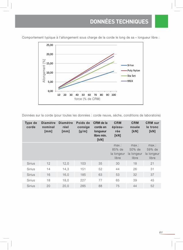
61
Comportement typique à l'allongement sous charge de la corde le long de sa « longueur l ibre :
DONNÉES TECHNIQUES
Allo
ngem
ent
[%]
force (% de CRM)
Données sur la corde (pour toutes les données : corde neuve, sèche, conditions de laboratoire)
max.: 85% de
la longeur l ibre
max.: 50% de
la longeur l ibre
max.: 59% de
la longeur l ibre
Sirius 12 12,0 103 35 30 18 21
Sirius 14 14,3 151 52 44 26 31
Sirius 16 16,0 185 63 53 32 37
Sirius 18 18,0 227 77 65 39 45
Sirius 20 20,0 285 88 75 44 52
Type de corde
Diamètre nominal
[mm]
Diamètreréel
[mm]
Poids de consige
[g/m]
CRM de la corde en longueur libre min.
[kN]
CRM épissu-
rée [kN]
CRM nouée [kN]
CRM sur le tronc
[kN]
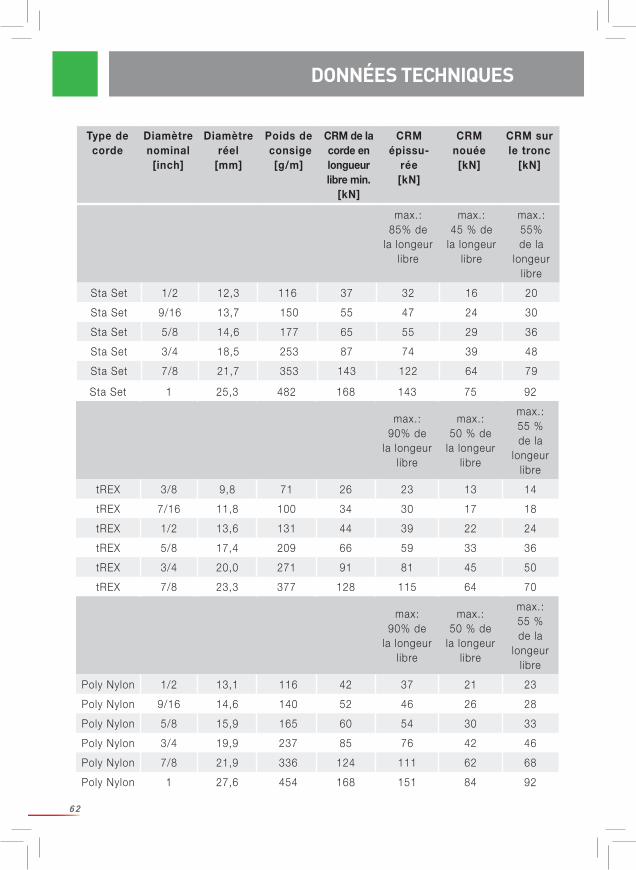
62
DONNÉES TECHNIQUES
Sta Set 1 25,3 482 168 143 75 92
max.: 90% de
la longeur l ibre
max.: 50 % de
la longeur l ibre
max.: 55 % de la
longeur l ibre
tREX 3/8 9,8 71 26 23 13 14
tREX 7/16 11,8 100 34 30 17 18
tREX 1/2 13,6 131 44 39 22 24
tREX 5/8 17,4 209 66 59 33 36
tREX 3/4 20,0 271 91 81 45 50
tREX 7/8 23,3 377 128 115 64 70
max: 90% de
la longeur l ibre
max.: 50 % de
la longeur l ibre
max.: 55 % de la
longeur l ibre
Poly Nylon 1/2 13,1 116 42 37 21 23
Poly Nylon 9/16 14,6 140 52 46 26 28
Poly Nylon 5/8 15,9 165 60 54 30 33
Poly Nylon 3/4 19,9 237 85 76 42 46
Poly Nylon 7/8 21,9 336 124 111 62 68
Poly Nylon 1 27,6 454 168 151 84 92
Type de corde
Diamètre nominal
[inch]
Diamètreréel
[mm]
Poids de consige
[g/m]
CRM de la corde en longueur libre min.
[kN]
CRM épissu-
rée [kN]
CRM nouée [kN]
CRM sur le tronc
[kN]
max.: 85% de
la longeur l ibre
max.: 45 % de
la longeur l ibre
max.: 55% de la
longeur l ibre
Sta Set 1/2 12,3 116 37 32 16 20
Sta Set 9/16 13,7 150 55 47 24 30
Sta Set 5/8 14,6 177 65 55 29 36
Sta Set 3/4 18,5 253 87 74 39 48
Sta Set 7/8 21,7 353 143 122 64 79
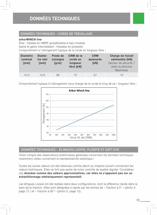
63
DONNÉES TECHNIQUES – CORDE DE TREUILLAGE
Diamètre nominal
[mm]
Diamè-tre réel
[mm]
Poids de consigne
[g/m]
CRM de la corde en longueur libre [kN]
CRM épissurée
[kN]
Charge de travail admissible [kN]
(facteur de sécurité 7 selon la directive
Machines)
12,0 12,6 98 70 57 10
Tenez compte des observations préliminaires générales concernant les données techniques, notamment celles concernant la représentativité statistique !
Toutes les autres valeurs ont été obtenues comme décrit au chapitre suivant concernant les valeurs techniques. Elles ne font pas partie de notre contrôle de qualité régulier. Considérez ces données comme des valeurs approximatives, car elles ne s'appuient pas sur un échantillonnage statistiquement représentatif.
Les élingues Loopie ont été testées dans deux configurations, dont la différence réside dans le sens de la traction. Elles sont désignées ci-après par les termes de « Traction à 0° » (photo 4, page 12 ) et « Traction à 90° » (photo 5, page 12).
arborWINCH lineÂme : tressée en HMPE (polyéthylène à haut module)Gaine et gaine intermédiaire : tressées en polyesterComportement à l'allongement typique de la corde en longueur l ibre :
DONNÉES TECHNIQUES – ÉLINGUES LOOPIE, PLOOPIE ET SOFT EYE
DONNÉES TECHNIQUES
0%
2%
4%
6%
8%
10%
12%
0% 10% 20% 30% 40% 50% 60% 70% 80% 90% 100%
Elon
gatio
n [%
]
Force [%]
Arbor Winch line
Allo
ngem
ent
[%]
force (% de CRM)
Comportement typique à l'allongement sous charge de la corde le long de sa « longueur l ibre :
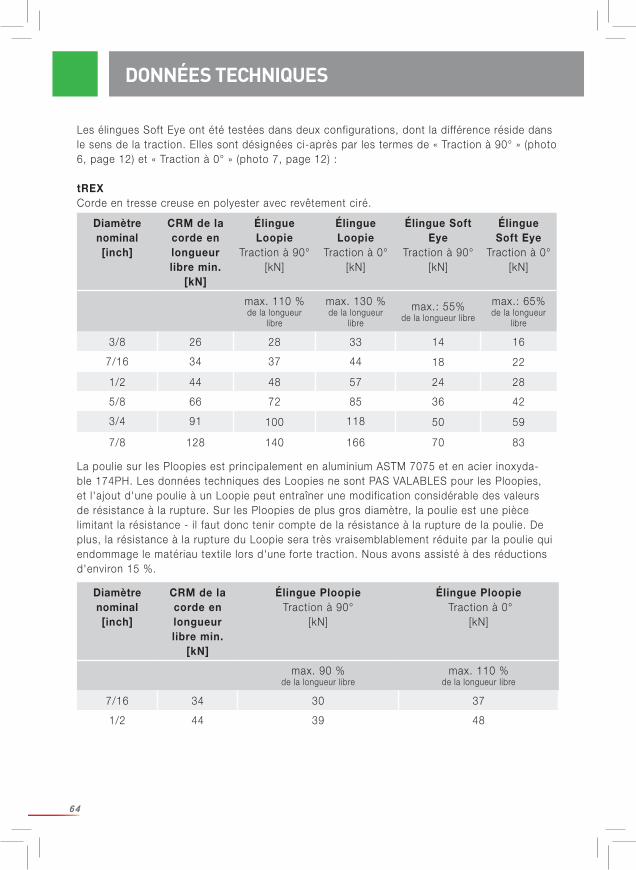
64
Les élingues Soft Eye ont été testées dans deux configurations, dont la différence réside dans le sens de la traction. Elles sont désignées ci-après par les termes de « Traction à 90° » (photo 6, page 12) et « Traction à 0° » (photo 7, page 12) :
tREXCorde en tresse creuse en polyester avec revêtement ciré.
La poulie sur les Ploopies est principalement en aluminium ASTM 7075 et en acier inoxyda-ble 174PH. Les données techniques des Loopies ne sont PAS VALABLES pour les Ploopies, et l'ajout d'une poulie à un Loopie peut entraîner une modification considérable des valeurs de résistance à la rupture. Sur les Ploopies de plus gros diamètre, la poulie est une pièce limitant la résistance - i l faut donc tenir compte de la résistance à la rupture de la poulie. De plus, la résistance à la rupture du Loopie sera très vraisemblablement réduite par la poulie qui endommage le matériau texti le lors d'une forte traction. Nous avons assisté à des réductions d'environ 15 %.
DONNÉES TECHNIQUES
Diamètre nominal [inch]
CRM de la corde en longueur libre min.
[kN]
Élingue Loopie
Traction à 90° [kN]
Élingue Loopie
Traction à 0°[kN]
Élingue Soft Eye
Traction à 90°[kN]
Élingue Soft Eye
Traction à 0°[kN]
max. 110 % de la longueur
libre
max. 130 % de la longueur
libre
max.: 55%de la longueur libre
max.: 65% de la longueur
libre
3/8 26 28 33 14 16
7/16 34 37 44 18 22
1/2 44 48 57 24 28
5/8 66 72 85 36 42
3/4 91 100 118 50 59
7/8 128 140 166 70 83
Diamètre nominal [inch]
CRM de la corde en longueur libre min.
[kN]
Élingue PloopieTraction à 90°
[kN]
Élingue Ploopie Traction à 0°
[kN]
max. 90 % de la longueur libre
max. 110 % de la longueur libre
7/16 34 30 37
1/2 44 39 48

65
PROPRIÉTÉS DES MATÉRIAUX DES FILS
PROPRIÉTÉS DES MATÉRIAUX
Matériau Polyester (polyéthylène téréphthalate)
Polyamide(polyamide 6)
HMPE(polyéthylène à haut module)
Caractéristiques électriques :
Résistivité électrique Ωcm 1011-1014 109-1012
Résistance électrique Ω >1014
Absorption d'humidité en atmosphère normale
% 0,2-0,5 3,5-4,5 0
Résistance chimique
Résistance aux acides Bonne par rapport aux acides miné-raux dilués et aux acides organiques
à température ambiante
Plus sensible que le polyester par rapport aux
acides dilués
Excellente
Résistance aux alcalis Suffisamment bonne.
Des solutions concentrées ou diluées chaudes
attaquent les fibres.
Très bonne résistance par
rapport aux les-sives à tempéra-ture ambiante.
Destruction des fibres à des
concentrations ou des tempéra-
tures élevées.
Excellente
Prudence avec les fluides à
action fortement oxydante.
Tout contact avec des produits chimiques est expressément déconseil lé !
Les indications sont tirées de la l ittérature spécialisée et se rapportent aux fi ls, c'est-à-dire à la matière première à partir de laquelle les cordes sont réalisées. Sources : Faserstoff-Tabellen nach P.-A. Koch : Polyesterfasern, 1993 et Polyamidfasern 1997Fact Sheets de DSM : CIS YA100 et CIS YA102 du 01/01/2008 ;
Comportement thermique :
Conductivité thermique W/mK 0,25 0,24 20 axial0,2 transveral
Intervalle de fusion °C 250-260 215-220 144-152
Résistance thermique durable
°C 120 90 70

66
Matériau Polyester (polyéthylène téréphthalate)
Polyamide(polyamide 6)
HMPE(polyéthylène à haut module)
Tenue au froid Faible augmenta-tion de la rigidité,
forte perte de l'allongement.
Très bonne rési-stance au froid.
Faible aug-mentation de
la rigidité, forte perte de l'allongement.
À -60°C : 110 % de la rigidi-té et 90 % de l'allongement, par rapport à
+23°C.
Exposition aux intempéries
Au bout d'1 d'exposition aux intempéries, en-
core 40 à 47% des doubles flexions
jusqu'à la rupture.
Stabil ité mo-yenne par rap-port à l'action de la lumière.
En essai réel (9 mois à l'air l ibre), résistance rési-
duelle similaire à celle du polyes-ter (46%) : 47%
Comportement au feu Ne continue pas à brûler, mais tend à
goutter.
Comme le polyester mais
brûle nettement si coloré ou
imprégné
Ne continue pas à brûler.
Élimination Déchets ménagers
Déchets ménagers
Déchets ménagers
PROPRIÉTÉS DES MATÉRIAUX
PROPRIÉTÉS DES MATÉRIAUX DE PIÈCES MÉTALLIQUES
Les informations sur les pièces métall iques se trouvent entre autres dans les instructions uti l i-sateur jointes au produit correspondant.Certaines valeurs du tableau ci-après proviennent de fiches de données matériaux et n'ont pas été mesurées sur le produit proprement dit. Certains facteurs peuvent influencer ces valeurs (par exemple, une couche d'anodisation entraîne une diminution drastique de la conductivité électrique).
Matériau Acier inoxydable 174PH Aluminium ASTM 7075
Caractéristiques électriques:
Résistivité électriqueΩcm 8*106 5,15*106
(une couce d'eloxal réduit la conductivité électrique)
Résistance électrique Ω
Absorption d'humidité % 0 0
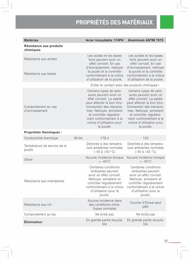
67
PROPRIÉTÉS DES MATÉRIAUX
Matériau Acier inoxydable 174PH Aluminium ASTM 7075
Résistance aux produits chimiques
Résistance aux acidesLes acides et les bases forts peuvent avoir un effet corrosif. En cas
d'encrassement, nettoyer la poulie et la contrôler
conformément à la notice d'uti l isation de la poulie.
Les acides et les bases forts peuvent avoir un effet corrosif. En cas
d'encrassement, nettoyer la poulie et la contrôler
conformément à la notice d'uti l isation de la poulie.
Résistance aux bases
Éviter le contact avec des produits chimiques !
Comportement en cas d'encrassement
Certains types de salis-sures peuvent avoir un effet corrosif. La saleté
peut affecter le bon fonc-tionnement des mécanis-mes. Nettoyer, entretenir
et contrôler régulière-ment conformément à la notice d'uti l isation pour
la poulie.
Certains types de salis-sures peuvent avoir un effet corrosif. La saleté
peut affecter le bon fonc-tionnement des mécanis-mes. Nettoyer, entretenir
et contrôler régulière-ment conformément à la notice d'uti l isation pour
la poulie.
Propriétés thermiques :
Conductivité thermique W/mk 178,4 130
Température de service de la poulie
Destinée à des tempéra-ture ambiantes normales
(-40 à +50 °C)
Destinée à des tempéra-ture ambiantes normales
(-40 à +50 °C)
GlaceAucune incidence lorsque
> -40°CAucune incidence lorsque
> -40°C
Résistance aux intempéries
Certaines conditions ambiantes peuvent
avoir un effet corrosif. Nettoyer, entretenir et
contrôler régulièrement conformément à la notice
d'uti l isation pour la poulie.
Certaines conditions ambiantes peuvent
avoir un effet corrosif. Nettoyer, entretenir et
contrôler régulièrement conformément à la notice
d'uti l isation pour la poulie.
Résistance aux UVAucune incidence dans des conditions clima-
tiques normales
Couche d'Eloxal peut pâlir
Comportement au feu Ne brûle pas Ne brûle pas
ÉliminationEn grande partie recycla-
bleEn grande partie recycla-
ble
PROPRIÉTÉS DES MATÉRIAUX
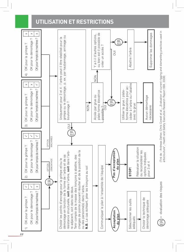
68
1)O
K p
our
la g
rimpe
?
OK
pou
r le
dém
onta
ge ?
OK
pour
l’em
ploi d
e m
achin
es ?
x
2)O
K p
our
la g
rimpe
?
OK
pou
r le
dém
onta
ge ?
OK p
our l’
emplo
i de
mac
hines
?
3)O
K p
our
la g
rimpe
?x
OK
pou
r le
dém
onta
ge ?
x
OK p
our l’
emplo
i de
mac
hines
?
4)O
K p
our
la g
rimpe
?x
OK
pou
r le
dém
onta
ge ?
x
OK p
our l’
emplo
i de
mac
hines
?x
Cho
isir
les
poin
ts d
'anc
rage
pou
r la
grim
pe e
t/ou
le
dém
onta
ge e
n fo
nctio
n de
la f
orm
e de
l'ar
bre
et d
e sa
ré
sist
ance
str
uctu
relle
, so
it d
ans
l'arb
re,
soit
dan
s l'a
rb-
re a
djac
ent,
soi
t da
ns le
s de
ux.
Teni
r co
mpt
e de
la m
asse
des
tro
nçon
s à
abat
tre,
des
ch
arge
s de
poi
nte
pouv
ant
résu
lter
et d
e la
pos
ition
de
la
ou d
es p
erso
nne(
s) d
ans
l'arb
re.
N.B
. Le
cas
éch
éant
, je
ter
les
tron
çons
au
sol
Uni
quem
ent
pour
3 e
t 4
: l'a
rbre
peu
t-il
être
sta
bilis
é po
ur la
gr
impe
ou
le d
émon
tage
, p.
ex.
par
hau
bann
age,
arr
imag
e ou
bo
ulon
nage
?
Com
mun
ique
r le
pla
n à
l'ens
embl
e de
l'éq
uipe
Acc
ès p
ar g
rue
ou
plat
e-fo
rme
élev
atric
e po
ssib
le ?
Y a
-t-i
l d'a
utre
s op
tions
, ou
bie
n es
t-il
poss
ible
de
crée
r un
acc
ès ?
Util
iser
la g
rue
/ pl
ate-
form
e él
evat
rice
pour
ac-
céde
r à
l'arb
re o
u l'a
batt
re
avec
la g
rue
Aba
ttre
l'ar
bre
Auc
un d
émon
tage
né
cess
aire
Sél
ectio
nner
les
outil
s ad
équa
tsS
TO
P!
Réé
valu
er la
situ
atio
n ou
rec
onsi
dére
r le
s op
tions
indi
quée
s po
ur 3
et
4
Acc
epta
tio
n d
u p
lan
Pas
d'a
ccep
tati
on
du
pla
n
ER
OU
I
OU
I
OU
I
NO
N
NO
N
OP
TIO
N
MA
CH
INE
S
OP
TIO
N
DÉ
MO
NTA
GE
=
-év
alua
tion
des
risqu
es
Sup
prim
er le
s do
mm
ages
Cho
isir
la t
echn
ique
de
dém
onta
ge a
déqu
ate
ER
ER
ER
ER
(Tiré
de
: A
ndre
as D
ette
r, C
hris
Cow
ell e
t al
., „
Eva
luat
ion
of c
urre
nt r
iggi
ng a
nd d
ism
antli
ng p
ract
ices
use
d in
ar
boric
ultu
re“,
Hea
lth a
nd S
afet
y E
xecu
tive
Res
earc
h R
epor
t 66
8, 2
008)
UTILISATION ET RESTRICTIONS
69
CONSIGNES À RESPECTER AVANT UTILISATIONAvant d'effectuer des opérations d'abattage par démontage : Réalisez une analyse précise des dangers. I l est de la responsabil ité de l'uti l isateur de veil ler à une analyse pertinente « mise à jour » des risques liés aux travaux à exécuter, et qui inclue également les cas d’urgence. Notamment, un contrôle visuel consciencieux de l'arbre doit avoir l ieu. Planifiez et organisez chacune des étapes. Tenez compte du fait que les divers tronçons d'un même arbre peuvent se comporter différemment. De ce fait, différentes mesures et techniques peuvent être requises pour différentes parties de l'arbre. En règle générale, l'abattage par démontage est un travail d'équipe. Faites en sorte que chaque membre de l'équipe connaisse son domaine de responsabil ités. Veil lez à établir une communication claire entre les personnes impliquées, en vous accordant sur des signaux vocaux / gestuels, et éventuellement en uti l isant un système radio ou similaire. I l est strictement interdit de se tenir sous la charge suspendue (danger de mort !). À cet égard, tenir compte du fait que le vent peut modifier nettement la courbe de chute d'un tronçon d'arbre, que le tronçon suspendu peut tourner ou dévier par rapport à son axe. Barrer l'accès sur un espace libre suffisamment grand, de manière que personne, et surtout pas les passants, ne puisse entrer involontairement dans la zone dangereuse ! Minimisez les risques et prenez des mesures visant à éviter les accidents. Avant l'uti l isation, i l est nécessaire de disposer d'un plan de sauvetage qui prenne en compte tous les cas d'urgence envisageables. Avant et pendant l'uti l isation, réfléchir à la manière dont les mesures de sauvetage peuvent être mises en œuvre efficacement et en toute sécurité. Ce faisant, analyser la situation de chacune des personnes impliquées. Spécifiez les facteurs de sécurité. Choisissez la technique de démontage la plus sûre pour votre cas d'application ! Choisissez ensuite l'équipement de démontage adapté dans la configuration qui convient. Prenez toutes les mesures assurant la sécurité du grimpeur ! Util isez l'équipement personnel requis pour la protection contre les chutes de hauteur (EPI) ! Le grimpeur et son EPI, c'est-à-dire le système qui assure sa sécurité, doivent se trouver hors de la courbe de chute que vont décrire le tronçon à enlever et l'équipement de démontage. Gardez à l'esprit qu'une rupture de la corde peut entraîner un retour élastique violent de la corde accompagnée du matériel projeté de l'arbre Une situation particulièrement critique apparaît lorsque le tronçon vient frapper le tronc et fait oscil ler l'arbre. L'équipe doit évaluer l' incidence des forces résultantes sur la structure d'ancrage et le ou les grimpeur(s), et prendre les mesures permettant de
UTILISATION ET RESTRICTIONS / SÉCURITÉ
UTILISATION ET RESTRICTIONSAvant d'uti l iser des cordes de démontage, demandez-vous si l'abattage par démontage est la méthode qui convient le mieux. Demandez-vous si grimper sur l'arbre est sûr et si, pour cet arbre, le démontage est une méthode sûre. L'abattage par démontage ne convient que si vous pouvez répondre par « oui » aux deux questions. Voyez également s'i l n'est pas plus sûr d'uti l iser des machines (grue, plate-forme de travail ou similaire) plutôt que de procéder à l'abattage par démontage.
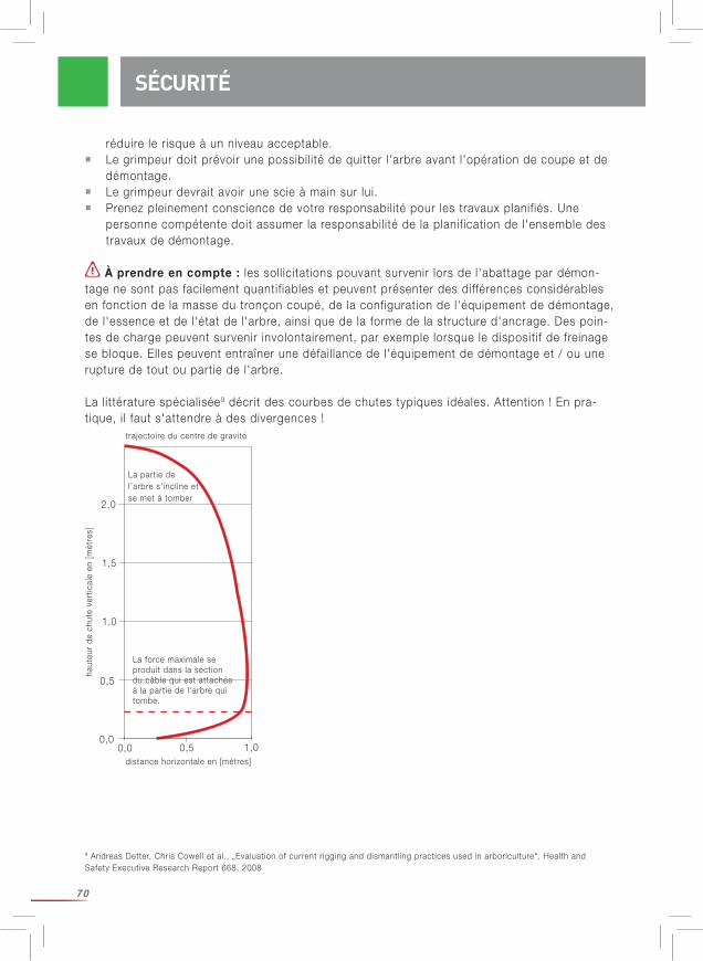
70
réduire le risque à un niveau acceptable. Le grimpeur doit prévoir une possibil ité de quitter l'arbre avant l'opération de coupe et de démontage. Le grimpeur devrait avoir une scie à main sur lui. Prenez pleinement conscience de votre responsabil ité pour les travaux planifiés. Une personne compétente doit assumer la responsabil ité de la planification de l'ensemble des travaux de démontage.
À prendre en compte : les soll icitations pouvant survenir lors de l'abattage par démon-tage ne sont pas facilement quantif iables et peuvent présenter des différences considérables en fonction de la masse du tronçon coupé, de la configuration de l'équipement de démontage, de l'essence et de l'état de l'arbre, ainsi que de la forme de la structure d'ancrage. Des poin-tes de charge peuvent survenir involontairement, par exemple lorsque le dispositif de freinage se bloque. Elles peuvent entraîner une défail lance de l'équipement de démontage et / ou une rupture de tout ou partie de l'arbre.
La l ittérature spécialisée9 décrit des courbes de chutes typiques idéales. Attention ! En pra-tique, i l faut s'attendre à des divergences !
9 Andreas Detter, Chris Cowell et al., „Evaluation of current rigging and dismantling practices used in arboriculture“, Health and Safety Executive Research Report 668, 2008
SÉCURITÉ
0,00,0
0,5 1,0
0,5
1,0
1,5
2,0
haut
eur
de c
hute
ver
tical
e en
[m
ètre
s]
distance horizontale en [mètres]
La partie de l’arbre s'incline et se met à tomber
La force maximale se produit dans la section du câble qui est attachée à la partie de l'arbre qui tombe.
trajectoire du centre de gravité

71
CHOIX
Avant d'installer un système de démontage, réalisez une analyse des dangers spécifique au lieu d'intervention prévu. Déterminez la disposition des différents composants. Coordonnez tous les composants en fonction de leurs performances. Pour ce faire, tenez compte de la charge limite dans la configuration choisie. Le contrôle visuel de l'arbre est une étape absolument essentielle de l' intervention. Demandez-vous quelles soll icitations pourraient sur-venir dans le pire des cas lors de l'abattage par démontage, et tenez compte de dommages invisibles sur l'arbre.
La capacité technique des cordes sèches à l'état neuf dans des conditions de laboratoire est indi-quée au chapitre « Données techniques ». Demandez-vous si elle est suffisante pour votre utilisation.
Dans ce contexte, prenez les points suivants en compte : Les soll icitations dynamiques occasionnent des forces nettement plus élevées que les soll icitations statiques. La terminaison de la corde présente une charge de rupture plus faible que la corde en longueur l ibre (les nœuds diminuent considérablement la charge de rupture de la corde - même une réduction de plus de 50% est possible. Dans le cas d'épissures correctement réalisées, i l faut s'attendre à une réduction de l'ordre de 10 à 20%). La disposition des cordes et élingues a une nette influence sur les forces qui agissent sur celles-ci. Vous devez toujours prévoir le scénario le plus pessimiste (« worst case ») et tenir compte d'incidents imprévus.
Les soll icitations dynamiques ont l ieu lorsqu'une charge en chute/oscil lante tombe dans le système de démontage. La soll icitation dynamique est d'autant plus importante que la charge est amortie rapidement ou brusquement. Dans de tels cas, la soll icitation dynamique peut facilement dépasser de loin la soll icitation statique. Votre travail doit être planifié de manière à éviter et/ou contrôler les soll icitations dynamiques.Prenez la charge maximale d’uti l isation des élingues d'ancrage en considération car les forces exercées peuvent être plus du double des forces agissant sur la corde de démontage.
Une personne compétente ayant été formée au calcul / à l'estimation des forces ex-ercées et connaissant leur rapport avec la masse du tronçon, la hauteur de chute, le type de corde, la longueur de la corde et d'autres grandeurs pertinentes, doit être présente sur le l ieu d'intervention pour gérer les opérations d'abattage par démontage.
Des études7 montrent que la soll icitation à laquelle l'élingue d'ancrage est soumise est 9 à 20 fois plus importante que la masse du tronçon de l'arbre. Attention ! I l ne s'agit là que d'une valeur indicative très approximative !
Assurez-vous que les propriétés de la corde conviennent bien à l'uti l isation prévue !
7 Brian Kane et al., « Forces and Stresses Generated During Rigging Operations », Arboriculture & Forestry 2009, 35(2), 68-7
CHOIX
72
Util isez un facteur de sécurité adéquat. Vous trouverez des recommandations permettant de choisir le bon facteur de sécurité dans la brochure « International Guideline on the Safer Use of Fiber Rope » (CI 1401) du Cordage Institute. Disponible gratuitement sur le site www.ropecord.com. Pour le levage de charges, la directive Machines 2006/42/CE recommande un facteur de sécurité minimum de 7 (rapport entre la charge de rupture de la corde neuve non confection-née et la charge de travail statique). La l ittérature spécialisée conseil le en outre de multiplier par le facteur 1,5 toutes les charges estimées8.
Tenez compte du fait que votre système n'est pas plus solide que son composant le plus faible.
Dérouler une bobine (fig. 8, page 19) :Si la corde est prélevée d'une bobine, le rouleau lui-même doit pouvoir tourner l ibrement. Pour ce faire, passez une barre par le centre du rouleau et déroulez la corde, ce qui fait tourner la bobine. N'enlevez jamais la corde d'un rouleau posé sur le côté, car la corde se tordrait.
Dérouler une aussière :Pour prélever la corde d'une aussière, i l est préférable de commencer par l'extrémité intérieure. Dérouler la corde dans le sens anti-horaire. Si la corde se déroule dans le sens horaire, des nœuds vont se former. Dans ce cas, réenroulez la corde comme elle l'était, retournez la aussiè-re et tirez une nouvelle fois la corde à partir du centre. Normalement, la corde devrait alors se dérouler dans le sens anti-horaire et sans nœud.
Nœuds :
Tenez compte du fait que chaque nœud réduit nettement la force de rupture. Lors de nos mesures, nous avons util isé un nœud de chaise double.
Instructions pour le nœud de chaise double (voir photo 9-13, page 20)
Épissure :
Tenez compte du fait que chaque épissure réduit la force de rupture. Vous ne devez réaliser une épissure par vous-même que si vous avez reçu la formation adéquate !Les instructions d'épissurage pour Sirius, Poly Nylon, Sta Set, arborWINCH line et tRex peuve-nt être téléchargées sur notre page d'accueil www.teufelberger.com. sont réunies en annexe. Nous déclinons toute responsabil ité pour des épissures ou tout autre confectionnement des cordes qui n'auront pas été effectués par TEUFELBERGER.
Élingue Loopie / Ploopie: Installez la poulie sur l'élingue Loopie et l issez soigneusement l'épissure (Photo 14-15, page 20)
Entourez l'arbre et faites passer la poulie par l'élingue Loopie. I l est possible d'ajuster la longueur de l'élingue Loopie : serrez étroitement l'élingue et vérif iez que l'élingue et la poulie tiennent bien. (Photo 16-18, page 21)
MISE EN SERVICE ET UTILISATION
8 Andreas Detter, Chris Cowell et al., Evaluation of current rigging and dismantling practices used in arboriculture, Health and Safety Executive Research Report 668, 2008
MISE EN SERVICE ET UTILISATION
73
Élingue Soft Eye : Installez l'œillet avec la poulie autour de l'arbre, comme représenté sur les photos suivantes. L'extrémité renforcée de la corde facil ite l'enfi lage. (Photo 19 - 24, page 21)
Fixez l'extrémité l ibre entre l'élingue et l'arbre. (Photo 25, page 22)
Installez ensuite la corde de travail avec un nœud de chaise double, comme décrit plus précisément au chapitre concernant les données techniques. (Photo 26 - 29, page 22)
Après l' installation, contrôlez le système ! Tenez les objets / surfaces abrasives et ayant des arêtes vives loin de la corde ! Le schéma à page 74 doit vous aider à réaliser vos travaux d'abattage par démontage en toute sécurité.
MISE EN SERVICE ET UTILISATION
Pour minimiser les forces résultantes, réduisez la masse du tronçon réduisez la longueur du tronçon mettez le bloc aussi près que possible de la zone de coupe mettez la poulie au-dessus de la zone de coupe (sur le même arbre ou sur des arbres / structures proches) évitez que la corde de travail ait du mou.
ATTENTION : i l ne s'agit que de recommandations de principe. Votre cas d'application concret peut présenter des raisons de s'écarter de ces principes.
Réduisez les mouvements de balancement autant que possible !
Une torsion de la corde (par rapport à l'axe longitudinal) en réduit la durée de vie ! Le motif sur la gaine des cordes Sirius aide à identif ier les torsions.
Les cordes ayant un allongement plus élevé peuvent absorber plus d'énergie. Toutes les cordes s'allongent - une corde longue plus qu'une courte. Plus la charge que vous appliquez est lourde, plus la corde s'allonge.Tenez cependant compte du fait que l'allongement est synonyme de danger ! Une corde étirée peut également faire bouger la charge d'une manière imprévisible ou dangereuse. Une corde étirée peut revenir brutalement à sa longueur d'origine et provoquer des blessures graves. N'enroulez jamais la corde autour de votre main ou de votre corps ! Pendant les travaux d'abattage par démontage, assurez-vous que vous ne vous tenez pas sur les cordes de démontage. Tenez les cordes de démontage (qui bougent rapidement) éloig-nées des branches, outils et autres objets. Tenez compte du fait que la hauteur de chute augmente avec l'allongement de la corde ! L'uti l isation de cordes ayant un allongement plus élevé peut faire qu'il sera diff ici le de contrôler de loin la partie sectionnée de l'arbre.
À respecter particulièrement pour l'utilisation de la corde de treuillage : Évitez de vous trouver dans l'alignement direct de la traction. Avec une charge en traction élevée, et du fait de l'élasticité du matériau synthétique, une énergie énorme se développe en
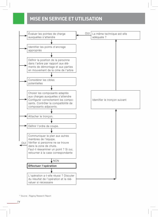
74
MISE EN SERVICE ET UTILISATION
12 Source : Rigging Research Report
Évaluer les pointes de charge auxquelles s'attendre
La même technique est-elle adéquate ?
Identif ier les points d'ancrage appropriés
Définir la position de la personne dans l'arbre par rapport aux élé-ments de démontage et aux parties en mouvement de la cime de l'arbre
Considérer les cibles potentielles
Choisir les composants adaptés aux charges auxquelles s'attendre Configurer correctement les compo-sants. Contrôler la compatibil ité de composants adjacents.
Identif ier le tronçon suivant
Attacher le tronçon.
Définir l'ordre de coupe.
Communiquer le plan aux autres membres de l'équipe.Vérif ier si personne ne se trouve dans la zone de chute.Faut-il réexaminer un point ? Si oui, retourner à la case correspondante
Effectuer l'opération
L'opération a-t-elle réussi ? Discuter du résultat de l'opération et la réé-valuer si nécessaire
OUI
OUI
NON

75
MISE EN SERVICE ET UTILISATION / CONTRÔLE RÉGULIER
cas de rupture de la corde, si bien qu'il y a un danger (de mort) extrême. En cas de tension ex-cessive de la corde, les personnes qui se trouvent sur sa trajectoire sont en danger. Si la corde casse, elle revient avec une force considérable. Cela peut provoquer des blessures graves pouvant entraîner la mort. Informez les membres de votre équipe de ce danger. Assurez-vous que personne, parmi vos collaborateurs et le public, ne se trouve dans la zone dangereuse. Lorsqu'une corde tourne en permanence dans un sens, comme c'est le cas avec un treuil, par exemple, faites-la tourner de temps en temps dans l'autre sens.
Utilisation avec d'autres éléments : S'assurer que les recommandations concernant une utilisation avec d'autres éléments soi-ent respectées. Assurez-vous que tous les composants sont bien compatibles ; en particulier, Choisissez un rapport D/d (diamètre du galet D par rapport au diamètre de la corde d) aussi grand que possible. Le diamètre de la gorge doit être adapté au diamètre de la corde. Assurez-vous que tous les composants sont correctement agencés.
Tout manquement à ces consignes augmente le risque de blessures graves ou mortelles.
CONTRÔLE RÉGULIER
AVERTISSEMENT - CONSIGNES DE SÉCURITÉEn règle générale : Si, pour quelque raison que ce soit, même si elle semble sans importance au premier abord, l'uti l isateur n'est pas sûr que le produit soit conforme, i l faut le retirer de la circulation et le rendre inutil isable, ou l' isoler et le marquer clairement et visiblement de manière à ce qu'il ne puisse pas être uti l isé par inadvertance. I l ne pourra être réutil isé qu'après contrôle par une personne qualif iée et sur autorisation écrite.
Après une charge d'impact violente, i l peut être nécessaire de remplacer la corde. La capacité de la corde à amortir des soll icitations dynamiques diminue avec l'uti l isation normale et les charges d'impact. Une corde usagée n'est plus aussi extensible qu'une corde neuve, et ne peut donc plus absorber autant d'énergie ; la charge de pointe augmente. Dans le même temps, la charge de rupture de la corde diminue.
Avant et après chaque intervention, contrôlez le produit comme décrit ci-dessous :Avant et après chaque util isation du produit, le soumettre à un contrôle visuel et tactile pour s'assurer qu'il est complet, prêt à l'emploi et qu'il fonctionne correctement.
Examinez la corde de tous les côtés et sur toute sa longueur. Palpez la corde, même si elle semble intacte, pour détecter sur l'âme des dommages cachés qui peuvent avoir été pro-voqués par exemple par un pliage fréquent ou par une sursoll icitation localisée. Recherchez avec attention les endroits thermiquement endommagés (surface de la corde ressemblant à du verre), ce qui peut être provoqué par un frottement important dans le système.
Veil lez particulièrement au segment de corde util isé dans la demi-clé sur le tronc d'arbre. Cette partie de la corde est habituellement celle qui est la plus fortement endommagée. Il peut être
76
ENTRETIEN / DURÉE DE VIE
nécessaire de couper cette partie de la corde et de réaliser une nouvelle épissure ou d'uti l iser l'autre extrémité de la corde. En cas de doute, éliminer le produit !
Il est absolument déconseillé d'utiliser des cordes présentant des signes d'usure. Uti-l isez exclusivement des cordes en parfait état, qui ne présentent aucune coupure, aucun nœud ni aucun brin arraché. Évitez toute abrasion de la corde par frottement contre des surfaces rugueuses. Recherchez avec attention des traces d'usure uniforme. Ne nouez en aucun cas une corde cassée, éliminez-la !
Nous recommandons de tenir un registre sur l'uti l isation (date, durée, conditions) et les inspec-tions (date, contrôleur, anomalies) de la corde. Notez qu'il faut également appliquer, le cas échéant, les législations nationales concernant les intervalles de contrôle.
Contrôlez toujours la corde entière, y compris les terminaisons et le matériel ! À la moindre incertitude, éliminer le produit ou le faire examiner par une personne qualifiée.
Liste de contrôle – l'examen doit comporter : Contrôle de l'état général : âge, intégralité, encrassement, assemblage correct. Contrôle de l'étiquette : étiquette présente et l isible oui/non, année de fabrication visible. Contrôle sur l'ensemble des composants, de l'absence de dommages mécaniques comme : incisions, fissures, entail les, usure par frottement, déformation, formation de nervures, vri l les / torsions non éliminables, écrasements, zones épaisses. Contrôle sur l'ensemble des composants, de l'absence de dommages thermiques ou chimiques comme : fusionnements, raidissements, durcissements, décolorations. Contrôle de l'absence de corrosion et de déformation sur les pièces métall iques. Contrôle de l'état et de l' intégralité des terminaisons, coutures (p. ex. pas d'usure par frottement du fi l à coudre), épissures (qui ne doivent pas glisser et se défaire, p. ex.), présence de nœuds.
Il est absolument indispensable de contrôler régulièrement l'équipement. Votre sécurité dé-pend de l'efficacité et de la solidité de l'équipement !
Pour de plus amples informations, nous vous renvoyons à la brochure CI 2001 — Fiber Rope Inspection and Retirement Criteria - du Cordage Institute. Disponible sur www.ropecord.com.
Les réparations ne doivent être effectuées que par le fabricant.
La durée de vie effective dépend exclusivement de l'état du produit, état qui dépend lui-même de nombreux facteurs (voir plus haut). Elle peut se réduire à une util isation unique en cas d'influences extrêmes, ou même moins si l'équipement a été endommagé avant même la pre-mière uti l isation (p. ex. pendant le transport).
ENTRETIEN
DURÉE DE VIE
77
TRANSPORT, STOCKAGE ET NETTOYAGE
La durée d'uti l isation peut atteindre jusqu'à 5 ans à compter de la date de fabrication, mais ce uniquement s'i l est rarement uti l isé (1 semaine par an) et stocké en bonne et due forme (voir Transport, stockage et nettoyage). L'année de fabrication est indiquée sur l'étiquette. S'i l n'est pas possible de déterminer avec certitude l'âge du produit, le retirer de la circulation.
Une usure mécanique, ou d'autres influences, comme l'action de la lumière solaire par ex-emple, réduisent fortement la durée de vie. Une décoloration ou une abrasion des fibres, un changement de teinte et des raidissements sont des signes caractéristiques qui attestent qu'il faut retirer le produit de la circulation. Consultez à ce sujet le chapitre « Contrôle régulier ».
I l n'est pas possible d'indiquer formellement une durée de vie universelle pour ce produ-it, puisque celle-ci dépend de divers facteurs, comme la lumière UV, le type et la fréquence d'uti l isation, l'entretien, l'exposition aux conditions climatiques (comme la glace ou la neige) et aux conditions environnementales (comme le sel, le sable, l'acide de batterie etc.), les contraintes thermiques (au-delà des conditions climatiques normales), la déformation et/ou le renflement mécaniques. Contrôlez toujours la corde entière, y compris les terminaisons et le matériel !
À la moindre incertitude, éliminer le produit ou le faire examiner par une personne qualifiée.
Le transport doit impérativement se faire à l'abri de la lumière et de la saleté et dans un em-ballage approprié (matériau hydrofuge et opaque).
Conditions d'entreposage : à l'abri des rayons UV (lumière solaire, postes à souder...), dans un endroit propre et sec, à température ambiante (15 – 25°C), à distance de produits chimiques (acides, bases, l iquides, vapeurs, gaz...) et d'autres conditions agressives, protégé contre les objets à arêtes vives.
I l vous faut donc stocker le produit dans un sac hydrofuge et opaque, dans un endroit sec et aéré. Ce faisant, évitez de tordre la corde !Veil lez à ce que le produit soit propre ! La saleté incrustée endommage la corde. Les cordes humides, encrassées peuvent pourrir.
Pour le nettoyage, uti l isez de l'eau tiède et une lessive pour l inge délicat. Ensuite, rincez l'équipement à l'eau claire et faites-le sécher avant de l'entreposer. Laissez sécher le produit de façon naturelle, sans le mettre à proximité du feu ou d'autres sources de chaleur. Pour la désinfection, n'util isez que des produits qui n'ont aucune influence sur les matières synthétiques employées.
En cas de non respect, c'est vous-même que vous mettez en danger !
TRANSPORT, STOCKAGE ET NETTOYAGE
78
DÉCLARATION DE CONFORMITÉ POUR LA CORDE À GRAND PAS DE TRESSAGE
Désignation a) Sirius 12 / 14 / 16 / 18 / 20mmb) arborWINCH line 12mm
Fonction Corde destinée au levage de charges pour uti l isation dans l'abattage par démontage
Modèle Voir la désignation
Type a) Corde avec âme tressée en PES / PESb) Corde avec âme tressée en HMPE / PES et gaine intermédiaire en PES.
Numéro de série Voir l'étiquetage sur la corde à grand pas de tressage
Appellation commer-ciale
Voir la désignation
La société : TEUFELBERGER Fiber Rope GmbH Vogelweiderstr. 50 A-4600 Welsdéclare par la présente que les machines ci-après désignées :
sont conformes aux dispositions de la directive « Sécurité machines » 2010, JO fédéral 2008_II_282, et donc à la directive « Machines » 2006/42/CE dans la version en vigueur.
Fait à Wels, le 20 janvier 2016 Fait à Wels, le 20 janvier 2016
Responsabilité technique Droit à délivrance DI. Rudolf Kirth Rainer Morawa, MBADirecteur technique Fiberrope Directeur administratif FiberropeTEUFELBERGER Fiber Rope GmbH TEUFELBERGER Fiber Rope GmbHVogelweiderstraße 50 Vogelweiderstraße 50A-4600 Wels A-4600 Wels
DÉCLARATION DE CONFORMITÉ
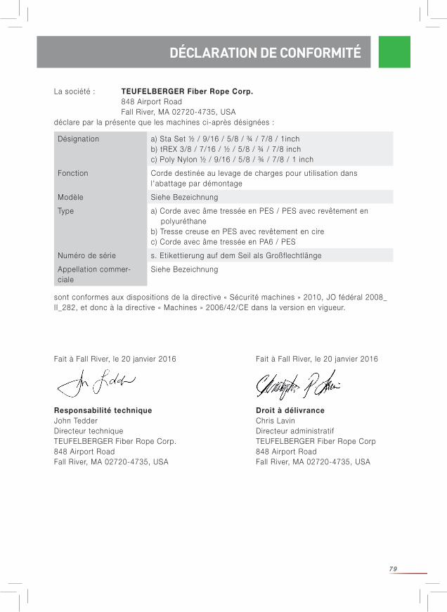
79
La société : TEUFELBERGER Fiber Rope Corp. 848 Airport Road Fall River, MA 02720-4735, USAdéclare par la présente que les machines ci-après désignées :
sont conformes aux dispositions de la directive « Sécurité machines » 2010, JO fédéral 2008_II_282, et donc à la directive « Machines » 2006/42/CE dans la version en vigueur.
Fait à Fall River, le 20 janvier 2016 Fait à Fall River, le 20 janvier 2016
Responsabilité technique Droit à délivrance John Tedder Chris LavinDirecteur technique Directeur administratif TEUFELBERGER Fiber Rope Corp. TEUFELBERGER Fiber Rope Corp848 Airport Road 848 Airport RoadFall River, MA 02720-4735, USA Fall River, MA 02720-4735, USA
Désignation a) Sta Set ½ / 9/16 / 5/8 / ¾ / 7/8 / 1inchb) tREX 3/8 / 7/16 / ½ / 5/8 / ¾ / 7/8 inchc) Poly Nylon ½ / 9/16 / 5/8 / ¾ / 7/8 / 1 inch
Fonction Corde destinée au levage de charges pour uti l isation dans l'abattage par démontage
Modèle Siehe Bezeichnung
Type a) Corde avec âme tressée en PES / PES avec revêtement en polyuréthane b) Tresse creuse en PES avec revêtement en cire c) Corde avec âme tressée en PA6 / PES
Numéro de série s. Etikettierung auf dem Seil als Großflechtlänge
Appellation commer-ciale
Siehe Bezeichnung
DÉCLARATION DE CONFORMITÉ
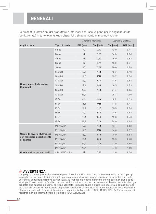
80
Le presenti informazioni del produttore e istruzioni per l’uso valgono per le seguenti corde (confezionate) in tutte le lunghezze disponibil i, singolarmente e in combinazione:
GENERALI
AVVERTENZAL’impiego di questi prodotti può essere pericoloso. I nostri prodotti potranno essere uti l izzati solo per gli impieghi per cui sono stati destinati. In particolare non dovranno essere uti l izzati per la protezione delle persone ai sensi della direttiva 89/686/EWG. E‘ obbligo del cliente garantire che gli operatori siano adde-strati per l’uso corretto e familiarizzati con le disposizioni di sicurezza necessarie. Tenete presente che ogni prodotto può causare dei danni se viene util izzato, immagazzinato o pulito in modo errato oppure sottopo-sto a carichi eccessivi. Verif icare le disposizioni nazionali di sicurezza, le raccomandazioni dei produttori e altre norme secondo le specifiche esigenze vigenti a l ivello locale. TEUFELBERGER® e 拖飞宝 sono marchi registrati a l ivello internazionale del gruppo TEUFELBERGER.
Diametro nominale Diametro effettivo
Applicazione Tipo di corda DM [mm] DM [inch] DM [mm] DM [inch]
Corde generali da lavoro(Bullrope)
Sirius 12 0,47 12,0 0,47
Sirius 14 0,55 14,3 0,56
Sirius 16 0,63 16,0 0,63
Sirius 18 0,71 18,0 0,71
Sirius 20 0,79 20,0 0,79
Sta Set 12,7 1/2 12,3 0,48
Sta Set 14,3 9/16 13,7 0,54
Sta Set 15,9 5/8 14,6 0,58
Sta Set 19,1 3/4 18,5 0,73
Sta Set 22,2 7/8 21,7 0,85
Sta Set 25,4 1 25,3 1,00
tREX 9,5 3/8 9,8 0,39
tREX 11,1 7/16 11,8 0,47
tREX 12,7 1/2 13,9 0,55
tREX 15,9 5/8 14,6 0,58
tREX 19,1 3/4 19,3 0,76
tREX 22,2 7/8 24,0 0,95
Corde da lavoro (Bullropes) con maggiore assorbimento di energia
Poly Nylon 12,7 1/2 13,1 0,52
Poly Nylon 14,3 9/16 14,6 0,57
Poly Nylon 15,9 5/8 15,9 0,63
Poly Nylon 19,1 3/4 19,9 0,78
Poly Nylon 22,2 7/8 21,9 0,86
Poly Nylon 25,4 1 27,6 1,09
Corda statica per verricelli arborWINCH line 12 0,47 12,6 0,50
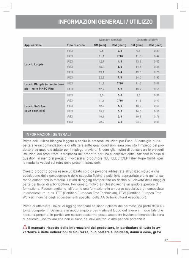
81
Prima dell’uti l izzo bisogna leggere e capire le presenti istruzioni per l’uso. Si consiglia di ris-pettare le raccomandazioni e di rif lettere sotto quali condizioni sarà previsto l’ impiego del pro-dotto e se questo è adatto per l’ impiego previsto. Si consiglia inoltre di conservare le presenti istruzioni del produttore in vicinanza del prodotto per una successiva consultazione! In caso di questioni in merito si prega di rivolgersi al produttore TEUFELBERGER Fiber Rope GmbH (per le modalità vedasi sul retro delle presenti istruzioni).
Questo prodotto dovrà essere uti l izzato solo da persone addestrate all’uti l izzo sicuro e che possiedono delle conoscenze e delle capacità fisiche e psichiche appropriate e che quindi sa-ranno competenti in materia. I lavori di rigging comportano un rischio più elevato della maggior parte dei lavori di arboricoltura. Per questo motivo è richiesto anche un grado superiore di formazione. Raccomandiamo all’utente una formazione in un corso specializzato riconosciuto in arboricoltura, p.es. ETT (Certif ied European Tree Technician), ETW (Certif ied Europea Tree Worker), nonché degli addestramenti specifici della AA (Arboricultural Association).
Prima di effettuare i lavori di rigging verif icare se siano richiesti dei permessi da parte delle au-torità competenti. Delimitare in modo ampio e ben visibile i l luogo del lavoro in modo tale che nessuna persona, in particolare nessun passante, possa accedere involontariamente alla zona di pericolo! Controllare che non ci siano dei cavi elettrici o altri pericoli potenziali!
Il mancato rispetto delle informazioni del produttore, in particolare di tutte le av-vertenze e delle indicazioni di sicurezza, può portare a incidenti, danni a cose, gravi
INFORMAZIONI GENERALI / UTILIZZO
INFORMAZIONI GENERALI
Laccio Soft Eye
(a un occhiello)
tREX 9,5 3/8 9,8 0,39
tREX 11,1 7/16 11,8 0,47
tREX 12,7 1/2 13,9 0,55
tREX 15,9 5/8 14,6 0,58
tREX 19,1 3/4 19,3 0,76
tREX 22,2 7/8 24,0 0,95
Diametro nominale Diametro effettivo
Applicazione Tipo di corda DM [mm] DM [inch1] DM [mm] DM [inch]
Laccio Loopie
tREX 9,5 3/8 9,8 0,39
tREX 11,1 7/16 11,8 0,47
tREX 12,7 1/2 13,9 0,55
tREX 15,9 5/8 14,6 0,58
tREX 19,1 3/4 19,3 0,76
tREX 22,2 7/8 24,0 0,95
Laccio Ploopie (= laccio Loo-
pie + rullo PINTO Rig)
tREX 11,1 7/16 11,8 0,47
tREX 12,7 1/2 13,9 0,55
82
lesioni e persino alla morte! In caso di lavori di rigging è molto elevato il rischio di riportare lesioni fisiche o causare danni a cose. Ogni uso non conforme alle presenti informazioni e il mancato rispetto di esse sono ritenuti un uso al di fuori del campo d'impiego definito e quindi un uso improprio e non adatto allo scopo definito/agli scopi definiti.
Bisogna scegliere i l dispositivo di protezione individuale (DPI) adatto per l’uso previsto dall’utente oppure prescritto per legge.
Rispettare eventuali disposizioni rilevanti (nazionali) di sicurezza per il rigging e per la scelta del DPI!
Consideriamo le presenti istruzioni sull’uso quale “work in progress”. Abbiamo effettuato in fabbrica delle simulazioni sottoponendo il prodotto a carichi dinamici e sono in programma ulteriori misurazioni di dati con carichi dinamici. I risultati disponibil i vengono pubblicati sul nostro sito www.teufelberger.com.
Per rigging s’intende il taglio di un albero in sezioni uti l izzando un sistema calcolato di solleva-mento consistente di funi tessil i, di rull i e (di regola) del tronco dell’albero come struttura ausil i-are naturale dimensionato in modo tale che regga alle forze che insorgono quando si prendono al volo le sezioni dell’albero in caduta, con delle masse assai elevate.
La corda (confezionata) allegata alle presenti informazioni del produttore è destinata esclusi-vamente all’uti l izzo quale parte di un sistema per lavori di rigging. Ricade nella responsabil ità dell'utente garantire la compatibil ità di ogni componente di un prodotto con componenti vicini.
Da rispettare: “I singoli componenti del sistema hanno un impatto reciproco che tut-tora non è ancora completamente esaminato e compreso. Durante i l rigging lo scalatore, l’attrezzatura e l’albero sono esposti a sollecitazioni molto elevate e diff ici lmente calcolabil i.1” Sarà compito dell’utente valutare e minimizzare i l rischio inerente.
TEUFELBERGER non è responsabile per gli effetti / per i danni diretti, indiretti o accidentali sopravvenuti durante o dopo l’uso del prodotto e dovuti ad un impiego improprio, inclusa la modifica delle corde (formazione di un occhiello, ecc.), combinazioni errate con altri compo-nenti oppure un assemblaggio poco favorevole.
I prodotti di rigging non devono essere uti l izzati quali dispositivi di protezione individuale (DPI).
E' importante contrassegnare l'attrezzatura di rigging in modo tale da escludere i l rischio di confusione con i DPI oppure da evitare che essa sia usata come tale.
UTILIZZO
1 Tratto da: Andreas Detter, „Le tecniche di rigging durante il taglio di alberi. Parte 1: analisi cinematiche“, Rivista AFZ-Der Wald 24/2008, pag.1322 ss.
UTILIZZO CONFORME ALL’USO PREVISTO
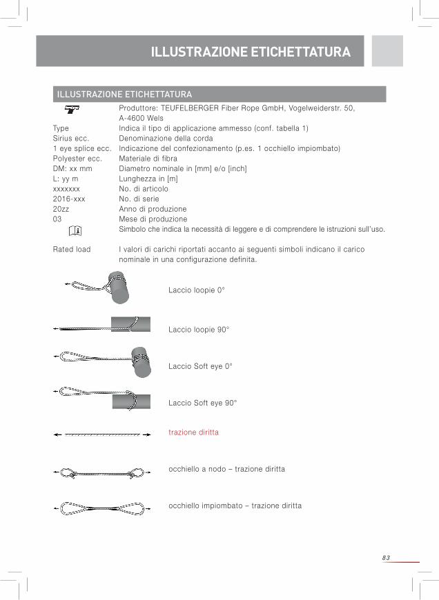
83
UTILIZZO
ILLUSTRAZIONE ETICHETTATURA
ILLUSTRAZIONE ETICHETTATURA
Produttore: TEUFELBERGER Fiber Rope GmbH, Vogelweiderstr. 50, A-4600 WelsType Indica i l t ipo di applicazione ammesso (conf. tabella 1)Sirius ecc. Denominazione della corda1 eye splice ecc. Indicazione del confezionamento (p.es. 1 occhiello impiombato)Polyester ecc. Materiale di f ibraDM: xx mm Diametro nominale in [mm] e/o [inch]L: yy m Lunghezza in [m]xxxxxxx No. di articolo2016-xxx No. di serie20zz Anno di produzione03 Mese di produzione Simbolo che indica la necessità di leggere e di comprendere le istruzioni sull’uso.
Rated load I valori di carichi riportati accanto ai seguenti simboli indicano il carico nominale in una configurazione definita.
Laccio loopie 0°
Laccio loopie 90°
Laccio Soft eye 0°
Laccio Soft eye 90°
trazione diritta
occhiello a nodo – trazione diritta
occhiello impiombato – trazione diritta
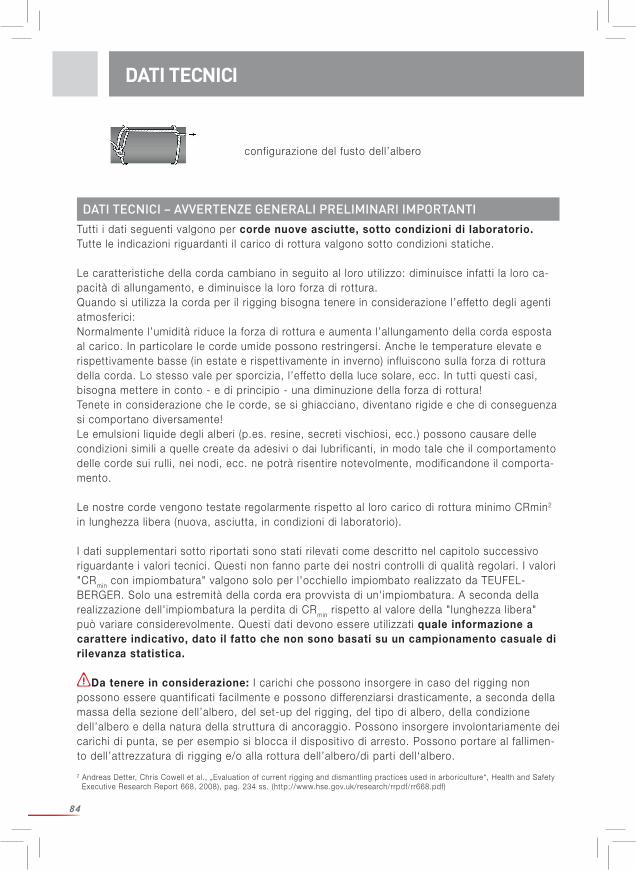
84
Tutti i dati seguenti valgono per corde nuove asciutte, sotto condizioni di laboratorio.Tutte le indicazioni riguardanti i l carico di rottura valgono sotto condizioni statiche.
Le caratteristiche della corda cambiano in seguito al loro uti l izzo: diminuisce infatti la loro ca-pacità di allungamento, e diminuisce la loro forza di rottura.Quando si uti l izza la corda per i l rigging bisogna tenere in considerazione l’effetto degli agenti atmosferici: Normalmente l’umidità riduce la forza di rottura e aumenta l’allungamento della corda esposta al carico. In particolare le corde umide possono restringersi. Anche le temperature elevate e rispettivamente basse (in estate e rispettivamente in inverno) influiscono sulla forza di rottura della corda. Lo stesso vale per sporcizia, l’effetto della luce solare, ecc. In tutti questi casi, bisogna mettere in conto - e di principio - una diminuzione della forza di rottura! Tenete in considerazione che le corde, se si ghiacciano, diventano rigide e che di conseguenza si comportano diversamente!Le emulsioni l iquide degli alberi (p.es. resine, secreti vischiosi, ecc.) possono causare delle condizioni simil i a quelle create da adesivi o dai lubrif icanti, in modo tale che il comportamento delle corde sui rull i, nei nodi, ecc. ne potrà risentire notevolmente, modificandone il comporta-mento.
Le nostre corde vengono testate regolarmente rispetto al loro carico di rottura minimo CRmin2 in lunghezza libera (nuova, asciutta, in condizioni di laboratorio).
I dati supplementari sotto riportati sono stati ri levati come descritto nel capitolo successivo riguardante i valori tecnici. Questi non fanno parte dei nostri controll i di qualità regolari. I valori "CRmin con impiombatura" valgono solo per l'occhiello impiombato realizzato da TEUFEL-BERGER. Solo una estremità della corda era provvista di un'impiombatura. A seconda della realizzazione dell' impiombatura la perdita di CRmin rispetto al valore della "lunghezza libera" può variare considerevolmente. Questi dati devono essere uti l izzati quale informazione a carattere indicativo, dato il fatto che non sono basati su un campionamento casuale di rilevanza statistica.
Da tenere in considerazione: I carichi che possono insorgere in caso del rigging non possono essere quantif icati facilmente e possono differenziarsi drasticamente, a seconda della massa della sezione dell’albero, del set-up del rigging, del tipo di albero, della condizione dell’albero e della natura della struttura di ancoraggio. Possono insorgere involontariamente dei carichi di punta, se per esempio si blocca il dispositivo di arresto. Possono portare al fall imen-to dell’attrezzatura di rigging e/o alla rottura dell’albero/di parti dell‘albero.
DATI TECNICI
configurazione del fusto dell’albero
2 Andreas Detter, Chris Cowell et al., „Evaluation of current rigging and dismantling practices used in arboriculture“, Health and Safety Executive Research Report 668, 2008), pag. 234 ss. (http://www.hse.gov.uk/research/rrpdf/rr668.pdf)
DATI TECNICI – AVVERTENZE GENERALI PRELIMINARI IMPORTANTI
85
DATI TECNICI
Le seguenti indicazioni ( l inee guida meramente indicative; non ci si assume nessuna responsa-bil ità per la correttezza delle informazioni) si basano esclusivamente su quanto indicato nella letteratura specializzata3: I l carico misurato durante i l test sul laccio di ancoraggio, a seconda della disposizione e dello scenario effettivo, è risultato da 9 a 20 volte superiore alla massa del pezzo dell’albero4. Per i dettagli si rimanda al Rigging Research Report. I l carico sulla corda da lavoro è spesso metà del carico riscontrato sul laccio di ancoraggio. (Attenzione: dipende fortemente dalla configurazione scelta!) Su tale base, per garantire che i componenti della corda non si rompano se vengono espo- sti a sollecitazioni d'urto, i l carico di rottura sul laccio di ancoraggio nella configurazione scelta dev'essere più di 9-20 volte superiore della massa del fusto dell'albero e i l carico di rottura della corda di rigging nella configurazione scelta dev'essere maggiore della metà del carico di rottura del laccio di ancoraggio. Inoltre bisogna scegliere un fattore di sicurezza sufficiente!
Da test dinamici effettuati in condizioni simulate, ma molto vicine a quelle reali, nell'ambito di una tesi assistita da Teufelberger e treemagineers sono stati ri levati valori indicativi differenti ( l inee guida meramente indicative; solo una serie definita di condizioni): I valori di resistenza alla rottura configurati in modo statico e dinamico sono molto vicini tra di loro in modo tale che i dati della stabil ità statica rappresentano un buon punto di riferimento per definire un carico limite di lavoro accettabile (Working Load Limit).
Si prega di prestare attenzione alle osservazioni preliminari generali riguardati i dati tecnici, in particolare per quanto riguarda la ri levanza statistica!
L’indicazione del CRmin con nodo vale per la seguente configurazione: con dei nodi è stato realizzato un occhiello sui due lati, uti l izzando la variante di gassa d’amante doppia (v. i l l. 1, pagina 9)
I l CRmin “sul fusto” è stato determinato come rappresentato nelle i l lustrazioni 2-3, pagina 9.
Informazioni riguardanti i l t ipo di realizzazione della corda:
DATI TECNICI – CORDE DA LAVORO/BULLROPES
3 Al posto della massa della parte dell’albero, e per correttezza in termini di f isica, si dovrebbe prendere come base il peso del pezzo dell’albero. Questo risulta quale massa [kg]*9,81m/s² ed è una forza espressa in [N]. In maniera semplif icata una massa di 1kg è equivalente ca. a 10 N = 1 daN = 0,01 kN.
Sirius Sta Set tREX Poly Nylon
AnimaIntreccio di poliestere
Intreccio di poliestere
Intreccio cavo di poliestere
con rivestimento cerato
Intreccio di poliammide PA6
MantoIntreccio di poliestere
Intreccio di poliestere con rivestimento
di poliuretano
Intreccio di poliestere
DATI TECNICI
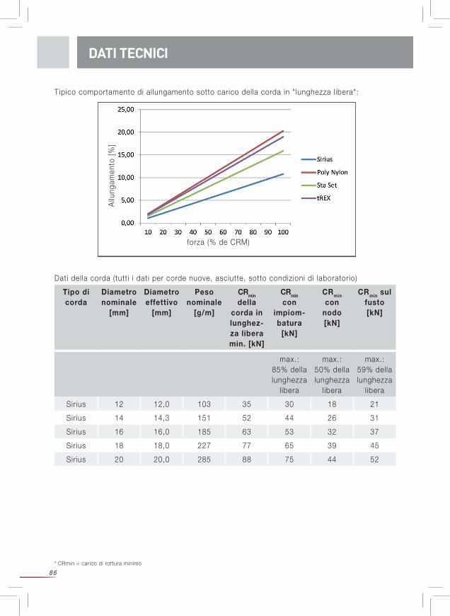
864 CRmin = carico di rottura minimo
Tipico comportamento di allungamento sotto carico della corda in "lunghezza libera":
DATI TECNICI
Dati della corda (tutti i dati per corde nuove, asciutte, sotto condizioni di laboratorio)
Allu
ngam
ento
[%
]
forza (% de CRM)
max.: 85% della lunghezza
libera
max.: 50% della lunghezza
libera
max.: 59% della lunghezza
libera
Sirius 12 12,0 103 35 30 18 21
Sirius 14 14,3 151 52 44 26 31
Sirius 16 16,0 185 63 53 32 37
Sirius 18 18,0 227 77 65 39 45
Sirius 20 20,0 285 88 75 44 52
Tipo di corda
Diametronominale
[mm]
Diametroeffettivo
[mm]
Peso nominale
[g/m]
CRmin
della corda in lunghez-za libera min. [kN]
CRmin
con impiom-batura
[kN]
CRmin con
nodo [kN]
CRmin sul fusto [kN]
87
DATI TECNICI
max.: 90% della lunghezza
libera
max.: 50 % della lunghezza
libera
max.: 55 % della lunghezza
libera
tREX 3/8 9,8 71 26 23 13 14
tREX 7/16 11,8 100 34 30 17 18
tREX 1/2 13,6 131 44 39 22 24
tREX 5/8 17,4 209 66 59 33 36
tREX 3/4 20,0 271 91 81 45 50
tREX 7/8 23,3 377 128 115 64 70
max: 90% della lunghezza
libera
max.: 50 % della lunghezza
libera
max.: 55 % della lunghezza
libera
Poly Nylon 1/2 13,1 116 42 37 21 23
Poly Nylon 9/16 14,6 140 52 46 26 28
Poly Nylon 5/8 15,9 165 60 54 30 33
Poly Nylon 3/4 19,9 237 85 76 42 46
Poly Nylon 7/8 21,9 336 124 111 62 68
Poly Nylon 1 27,6 454 168 151 84 92
max.: 85% della lunghezza
libera
max.: 45% della lunghezza
libera
max.: 55% della lunghezza
libera
Sta Set 1/2 12,3 116 37 32 16 20
Sta Set 9/16 13,7 150 55 47 24 30
Sta Set 5/8 14,6 177 65 55 29 36
Sta Set 3/4 18,5 253 87 74 39 48
Sta Set 7/8 21,7 353 143 122 64 79
Sta Set 1 25,3 482 168 143 75 92
Tipo di corda
Diametronominale
[inch]
Diametroeffettivo
[mm]
Peso nominale
[g/m]
CRmin
della corda in lunghez-za libera min. [kN]
CRmin
con impiom-batura
[kN]
CRmin con
nodo [kN]
CRmin sul fusto [kN]
DATI TECNICI
88
DATI TECNICI – CORDE PER VERRICELLI
Diametro nominale
[mm]
Diametro effettivo
[mm]
Peso nominale
[g/m]
CRmin della corda in
lunghezza libera [kN]
CRmin con impiombatu-
ra [kN]
Carico di lavoro am-messo [kN]
(fattore di sicurezza 7 conf. alla Direttiva delle
macchine)
12,0 12,6 98 70 57 10
0%
2%
4%
6%
8%
10%
12%
0% 10% 20% 30% 40% 50% 60% 70% 80% 90% 100%
Elon
gatio
n [%
]
Force [%]
Arbor Winch line
arborWINCH lineAnima: intrecciata di HMPE (polieti lene ad alta modularità)Manto e guaina intermedia: intrecciati di poliestere
Comportamento tipico di allungamento della corda in lunghezza libera:
T ipico comportamento di allungamento sotto carico della corda in "lunghezza libera":
Allu
ngam
ento
[%
]
forza (% de CRM)
DATI TECNICI – LACCI LOOPIE, PLOOPIE E SOFT EYE
Si prega di prestare attenzione alle osservazioni preliminari generali riguardati i dati tecnici, in particolare per quanto riguarda la ri levanza statistica!
Tutti gli altri valori sono stati ri levati come descritto nel capitolo successivo riguardante i valoritecnici. Questi non fanno parte dei nostri controll i regolari di qualità. Questi dati devono essereutil izzati quale informazione a carattere indicativo, dato i l fatto che non sono basati suun campionamento casuale di ri levanza statistica.
DATI TECNICI
89
CARATTERISTICHE
I lacci Loopie sono stati testati in due disposizioni, contraddistinti fra di loro dalla direzione ditrazione. In seguito vengono denominati quale versione con “trazione in 0°” (immagine 4, pagi-na 12) e “trazione in 90°” (immagine 5, pagina 12).
I lacci Soft Eye sono stati testati in due disposizioni, contraddistinte fra di loro dalla direzionedi trazione. Di seguito vengono denominati quale versione con “trazione in 90°” (immagine 6, pagina 12) e “trazione in 0°” (immagine 7, pagina 12):
tREXCorda di intreccio cavo di poliestere con rivestimento cerato
Diametro nominale
[inch]
CRmin della corda in
lunghezza libera[kN]
Laccio Loopie
Trazione in 90° [kN]
LaccioLoopie
Trazione in 0°[kN]
LaccioSoft Eye
Trazione in 90°[kN]
LaccioSoft Eye
TTrazione in 0°[kN]
max. 110 % della lunghezza
libera
max. 130 % della lunghezza
libera
max.: 55% della lunghezza
libera
max.: 65% della lunghezza
libera
3/8 26 28 33 14 16
7/16 34 37 44 18 22
1/2 44 48 57 24 28
5/8 66 72 85 36 42
3/4 91 100 118 50 59
7/8 128 140 166 70 83
Il rullo uti l izzato per i Ploopie consiste in gran parte di alluminio ASTM 7075 e acciaio inossi-dabile 174PH. I dati tecnici dei lacci Loopie NON VALGONO per i Ploopie e aggiungendo un rullo a un laccio Loopie può provocare delle modifiche considerevoli dei valori di resistenza alla rottura. In caso di Ploopie con diametro maggiore i l rullo costituisce il fattore l imitante della stabil ità - per cui bisogna badare alla resistenza alla rottura del rullo. La resistenza alla rottura del laccio Loopie molto probabilmente viene ridotta dal rullo che danneggia i l materiale tessile durante l'esposizione a forte trazione. Abbiamo riscontrato delle riduzioni di ca. i l 15%.
Diametronominale
[inch]
CRmin della corda in
lunghezza libera [kN]
Laccio PloopieTrazione in 90°
[kN]
Laccio Ploopie Trazione in 0°
[kN]
max. 90 % della lunghezza libera
max. 110 % della lunghezza libera
7/16 34 30 37
1/2 44 39 48
DATI TECNICIDATI TECNICI
90
CARATTERISTICHE DEI FILI
Materiale Poliestere (polieti lene tereftalato)
Poliammide(poliammide 6)
HMPE(polieti lene ad
alta modularità)
Caratteristiche elettriche:
Resistenza elettrica specifica
Ωcm 1011-1014 109-1012
Resistenza elettrica Ω >1014
Assorbimento di umidità in clima normale
% 0,2-0,5 3,5-4,5 0
Resistenza chimica
Resistenza agli acidi Buona resistenza agli acidi minerali diluiti e agli acidi organici a tempe-ratura ambiente
Più sensibile del poliestere agli
acidi diluiti
eccellente
Resistenza agli alcali Sufficientemente buona.
Delle soluzioni concentrate e risp. diluite calde attac-
cano le fibre.
Resistenza particolarmente buona alle so-luzioni alcaline a temperatura
ambiente.In caso di
concentrazioni alte o tempera-ture elevate le fibre vengono
distrutte.
eccellente
Attenzione in caso di mezzi a forte effetto
ossidante.
Si avverte espressamente di evitare i l contatto con materie chimiche!
Le seguenti indicazioni sono state ri levate dalla letteratura e sono riferite ai f i l i, e quindi alla materia prima dalla quale vengono fatte le corde. Fonti: Tabelle delle materie fibrose secondo P.-A. Koch: fibre di poliestere, 1993 e fibre di poli-ammide 1997Fact Sheets di DSM: CIS YA100 e CIS YA102 del 01-01-2008;
Comportamento termico:
Conducibil ità termica W/mK 0,25 0,24 20 axial0,2 transveral
Fascia di fusione °C 250-260 215-220 144-152
CHARATTERISTICHE DEI FILI
91
Materiale Poliestere (polieti lene tereftalato)
Poliammide(poliammide 6)
HMPE(polieti lene ad
alta modularità)
Resistenza permanente al calore
°C 120 90 70
Comportamento al freddo
Scarso aumento di stabil ità, forte
perdita di allunga-mento.
Resistenza molto buona al
freddo. Scarso aumento di stabil ità, forte perdita di allun-
gamento.
A -60°C il 110% della stabil ità e i l 90% dell’allunga-mento rispetto a
+23°C.
Esposizione agli agenti atmosferici
Dopo 1 anno di esposizione agli
agenti atmosferici ancora i l 40-47%
delle flessioni doppie fino alla
rottura.
Scarsa stabil ità se esposto alla
luce.
Nel test reale (9 mesi all‘aperto) una resistenza residua simi-le come per i l
poliestere (46%): 47%
Comportamento al fuoco Non continua a bruciare, ma tende
a gocciolare
Come polies-tere. Brucia però note-
volmente, se è colorato o impregnato
Non continua a bruciare.
Smaltimento Rifiuti domestici Rifiuti domestici Rifiuti domestici
CARATTERISTICHE DEGLI ELEMENTI DI METALLO
CARATTERISTICHE DEGLI ELEMENTI DI METALLO
Le informazioni riguardanti gli elementi di metallo si trovano anche nelle rispettive istruzioni per l'utente fornite in dotazione con il prodotto.Alcuni valori indicati nella seguente tabella provengono da schede dati dei materiali e non sono stati misurati sul prodotto stesso. Determinati fattori possono avere un influsso su questi valori (p. es. un rivestimento di eloxal riduce drasticamente la conducibil ità elettrica).
Materiale Acciaio inossidabile 174PH
Alluminio ASTM 7075
Caratteristiche elettriche:
Resistenza elettrica specifica
Ωcm 8*1065,15*106
(Anodizing layer reduces conductivity)
Resistenza elettrica Ω
Assorbimento di umidità % 0 0
CHARATTERISTICHE DEI FILI
92
Materiale Acciaio inossidabile 174PH
Alluminio ASTM 7075
Resistenza chimica
Resistenza agli acidiAcidi e alcali forti possono avere un’azione corrosiva.
In caso di inquinamento bisogna pulire e controllare
i l rullo conformemente a quanto indicato nelle istru-
zioni per l’uso del rullo.
Acidi e alcali forti possono avere un’azione corrosiva.
In caso di inquinamento bisogna pulire e controllare
i l rullo conformemente a quanto indicato nelle istru-
zioni per l’uso del rullo.
Resistenza agli alcali
Evitare i l contatto con sostanze chimiche!
Comportamento in caso di inquinamento
Certi tipi di sostanze inquinanti possono avere un’azione corrosiva. La
sostanza inquinante può compromettere i l funzi-onamento corretto dei
meccanismi.Effettuare regolarmente
interventi di pulizia, manutenzione e controllo conformemente a quanto
indicato nelle istruzioni per l’uso del rullo.
Certi tipi di sostanze inquinanti possono avere un’azione corrosiva. La
sostanza inquinante può compromettere i l funzi-onamento corretto dei
meccanismi.Effettuare regolarmente
interventi di pulizia, manutenzione e controllo conformemente a quanto
indicato nelle istruzioni per l’uso del rullo.
Comportamento termico:
Conducibil ità termica W/mk 178,4 130
Temperature d’esercizio del rullo
Adatto per le temperature ambientali normali (da -40
a +50 °C)
Adatto per le temperature ambientali normali (da -40
a +50 °C)
Ghiaccio Nessun effetto se > -40°C Nessun effetto se > -40°C
Resistenza agli agenti atmosferici
Determinate condizioni atmosferiche possono
avere un’azione corrosiva. Effettuare regolarmente
interventi di pulizia, manutenzione e controllo conformemente a quanto
indicato nelle istruzioni per l’uso del rullo.
Determinate condizioni atmosferiche possono
avere un’azione corrosiva. Effettuare regolarmente
interventi di pulizia, manutenzione e controllo conformemente a quanto
indicato nelle istruzioni per l’uso del rullo.
Resistenza ai raggi UVNessun effetto in caso di condizioni atmosferiche
normali
I l r ivestimento di eloxal può scolorire
Comportamento al fuoco non brucia non brucia
Smaltimentoin gran parte adibito a
ricicloin gran parte adibito a
riciclo
CHARATTERISTICHE DEGLI ELEMENTI DI METALLO
93
1)O
K p
er a
rram
pica
rsi?
OK
per
far
e il
riggi
ng?
OK
per l
’impi
ego
di m
acch
ine?
x
2)O
K p
er a
rram
pica
rsi?
OK
per
far
e il
riggi
ng?
OK p
er l’
impi
ego
di m
acch
ine?
3)O
K p
er a
rram
pica
rsi?
x
OK
per
far
e il
riggi
ng?
x
OK p
er l’
impi
ego
di m
acch
ine?
4)O
K p
er a
rram
pica
rsi?
x
OK
per
far
e il
riggi
ng?
x
OK p
er l’
impi
ego
di m
acch
ine?
x
Sce
glie
re i
punt
i di a
ncor
aggi
o pe
r ar
ram
pica
rsi e
/o il
rig
ging
con
form
emen
te a
lla f
orm
a de
ll’al
bero
e d
ella
sua
fo
rza
stru
ttur
ale;
o n
ell’a
lber
o o
nell’
albe
ro a
ccan
to o
in
tutt
i e d
ue.
Tene
re in
con
side
razi
one
la m
assa
del
le p
arti
da t
aglia
-re
, i c
aric
hi d
i pun
ta d
a as
pett
arsi
e la
pos
izio
ne d
ella
/e
pers
ona/
e ne
ll’al
bero
.N
OTA
: D
ove
è il
caso
, fa
r ca
dere
i pe
zzi.
Per
no.
3 o
4:
E’
poss
ibile
sta
biliz
zare
l’al
bero
per
sal
irci o
per
fa
re il
rig
ging
? p.
es.
stra
lland
olo,
riz
zand
olo
o fis
sand
olo
con
bullo
ni.
Info
rmar
e tu
tta
la s
quad
ra d
el p
roge
tto
prev
isto
.
Acc
esso
con
la g
ruo
piat
tafo
rma?
Ci s
ono
altr
e op
zion
i op
pure
si p
uò c
rear
e un
ac
cess
o?
Util
izza
re u
na g
ru/p
iatt
a-fo
rma
per
aver
e un
acc
es-
so o
ppur
e ta
glia
re l’
albe
ro
con
la g
ruTa
glia
re l’
albe
ro
Non
è n
eces
sario
il
riggi
ng.
Sce
glie
re g
li ut
ensi
li ap
pro-
pria
ti.S
TO
P!
Riv
alut
are
la s
ituaz
i -on
e o
rifle
tter
e nu
o-va
men
te le
opz
ioni
in
conf
orm
ità a
i pun
ti 3
o 4.
Co
nco
rdan
za s
ul
pro
get
toM
anca
ta c
on
cord
anza
su
l p
rog
etto
VR
SÌ
SÌ
SÌ
NO
NO
OP
ZIO
NE
MA
CC
HIN
E
OP
ZIO
NE
RIG
GIN
G
=
Val
utaz
ione
del
ris
chio
Rim
edia
re a
i dan
ni.
Sce
glie
re la
tec
nica
app
ro-
pria
ta d
i rig
ging
.
VR
VR
VR
VR
(And
reas
Det
ter,
Chr
is C
owel
l et
al.,
„E
valu
atio
n of
cur
rent
rig
ging
and
dis
man
tling
pra
ctic
es u
sed
in
arbo
ricul
ture
“, H
ealth
and
Saf
ety
Exe
cutiv
e R
esea
rch
Rep
ort
668,
200
8)
UTILIZZO E LIMITI DI UTILIZZOCHARATTERISTICHE DEGLI ELEMENTI DI METALLO
94
DA RISPETTARE PRIMA DELL‘UTILIZZOPrima di effettuare i lavori di rigging: Effettuare un’analisi approfondita dei rischi. Ricade nella responsabil ità dell’utente disporre di una valutazione ri levante e “attualizzata” dei rischi per i lavori da realizzare che com- prenda anche i casi di emergenza. In particolare bisogna eseguire un accurato controllo visivo dell’albero. Progettare ed organizzare tutti i passi da intraprendere. Tenere in considerazione che i singoli segmenti dello stesso albero possono distinguersi per i l loro comportamento. Perciò potrebbero essere necessari anche degli interventi e delle tecniche differenti per i singoli segmenti dell‘albero. Normalmente i l rigging è un lavoro di squadra. Bisogna provvedere a che ogni membro della squadra conosca i propri ambiti di responsabil ità. Garantire una comunicazione chiara fra tutti i membri della squadra concordando dei segni vocali o gestuali, eventualmente anche impiegando apparecchi radiotrasmittenti o simil i. E` rigorosamente vietato sostare sotto i l carico sospeso (pericolo di vita!). A questo proposito bisogna tenere in considerazione che a causa del vento la curva di caduta di un segmento di un albero può essere notevolmente deviata, che il segmento di un albero in sospeso sia girato oppure possa essere deviato dalla sua direzione assiale. Bisogna delimitare abbondantemente lo spazio l ibero e l imitare l’accesso in modo tale che nessuno, e in particolare nessun passante possa accedere involontariamente alla zona di pericolo. Si faccia in modo di minimizzare i rischi e si provveda a porre in essere le misure per evitare incidenti. Prima dell’uti l izzo dev’essere a disposizione un piano per gli interventi di emergenza che tenga in considerazione tutti i casi di emergenza possibil i. Prima e durante l’uti l izzo bisogna ragionare come si potranno porre in essere in modo sicuro e efficace le misure di emergenza. Bisogna analizzare la situazione di ogni singolo partecipante. Stabil ire i fattori di sicurezza. Scegliere la tecnica di rigging più sicura per l’ impiego previsto! Scegliere l’attrezzatura appropriata di rigging nella configurazione adatta. Porre in essere tutte le misure per la sicurezza della persona che si arrampica! Util izzare i dispositivi di protezione individuale necessari (DPI) per proteggere gli operatori da eventuali cadute! L’arrampicatore e i suoi DPI, e cioè i l sistema per mezzo del quale è assicurato, devono trovarsi al di fuori della curva di caduta che sarà descritta dal segmento dell’albero da tagliare e dall’attrezzatura per i l rigging. Bisogna tenere in considerazione che in caso di rottura della corda questa potrebbe sbalzare fortemente indietro facendo muovere degli accessori della corda verso la parte alta dell’albero.
UTILIZZO E LIMITI DI UTILIZZO / AVVERTENZAA
UTILIZZO E LIMITI DI UTILIZZO
Prima di uti l izzare le corde da rigging bisognerà valutare se i l rigging sia i l metodo più appro-priato. Bisogna infatti chiarire se è sicuro arrampicarsi sull’albero e se è sicuro tagliare l’albero con il metodo del rigging. Solo se si risponde in modo affermativo ad ambedue le domande, è i l caso di lavorare secondo il metodo del rigging. Riflettete anche se sia più sicuro impiegare delle macchine (gru, piattaforme elevatrici o simil i) al posto del rigging.
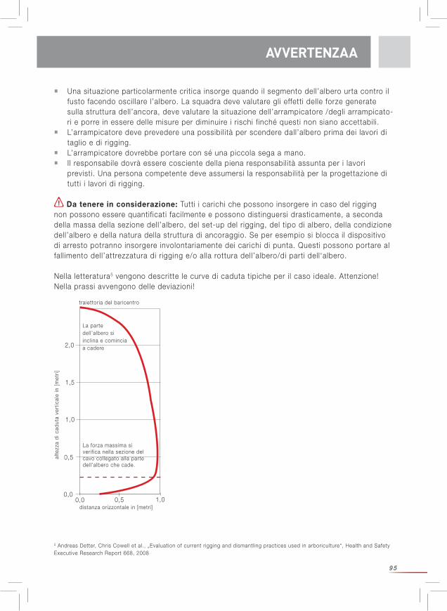
95
UTILIZZO E LIMITI DI UTILIZZO / AVVERTENZAA
Una situazione particolarmente critica insorge quando il segmento dell’albero urta contro i l fusto facendo oscil lare l’albero. La squadra deve valutare gli effetti delle forze generate sulla struttura dell’ancora, deve valutare la situazione dell’arrampicatore /degli arrampicato- ri e porre in essere delle misure per diminuire i rischi finché questi non siano accettabil i. L’arrampicatore deve prevedere una possibil ità per scendere dall’albero prima dei lavori di taglio e di rigging. L’arrampicatore dovrebbe portare con sé una piccola sega a mano. I l responsabile dovrà essere cosciente della piena responsabil ità assunta per i lavori previsti. Una persona competente deve assumersi la responsabil ità per la progettazione di tutti i lavori di rigging.
Da tenere in considerazione: Tutti i carichi che possono insorgere in caso del rigging non possono essere quantif icati facilmente e possono distinguersi drasticamente, a seconda della massa della sezione dell’albero, del set-up del rigging, del tipo di albero, della condizione dell’albero e della natura della struttura di ancoraggio. Se per esempio si blocca il dispositivo di arresto potranno insorgere involontariamente dei carichi di punta. Questi possono portare al fall imento dell’attrezzatura di rigging e/o alla rottura dell’albero/di parti dell‘albero.
Nella letteratura5 vengono descritte le curve di caduta tipiche per i l caso ideale. Attenzione! Nella prassi avvengono delle deviazioni!
5 Andreas Detter, Chris Cowell et al., „Evaluation of current rigging and dismantling practices used in arboriculture“, Health and Safety Executive Research Report 668, 2008
AVVERTENZAA
0,00,0
0,5 1,0
0,5
1,0
1,5
2,0
alte
zza
di c
adut
a ve
rtic
ale
in [
met
ri]
distanza orizzontale in [metri]
La parte dell’albero si inclina e comincia a cadere
La forza massima si verif ica nella sezione del cavo collegato alla parte dell’albero che cade.
traiettoria del baricentro
96
6 Brian Kane et al., „Forces and Stresses Generated During Rigging Operations“, Arboriculture & Forestry 2009, 35(2), 68-74.
SCELTA
SCELTA
Prima di installare un sistema di rigging, effettuare un’analisi del rischio focalizzando sul luogo di impiego previsto. Determinare come disporre i singoli componenti. Bisogna armonizzare la capacità di prestazione di tutti i componenti. Prendere come base la capacità di carico nella configurazione scelta. I l controllo visivo dell’albero è un passo di importanza essen-ziale. Bisogna rif lettere quali carichi possono insorgere durante i l rigging nella peggiore delle ipotesi e tenere in considerazione anche i danni invisibil i sull‘albero.
Le capacità di resil ienza delle corde asciutte in stato nuovo sotto condizioni di laboratorio è indicata nel capitolo “Dati tecnici”. Bisogna valutare se sia sufficiente per l’ impiego previsto.
Bisogna tenere in considerazione, che i carichi dinamici portano a forze notevolmente maggiori di quell i statici, che i collegamenti di corde presentano un minore carico di rottura che una corda in lung- hezza libera. (Dei nodi abbassano notevolmente i l carico di rottura della corda – è persino possibile una riduzione di più del 50%. In caso di impiombature correttamente eseguite bisogna tenere in conto una riduzione del 10-20%.) che la disposizione delle corde e dei lacci influiscono in modo essenziale sulle forze che agiscono su di loro che per motivi di sicurezza bisogna sempre partire dal caso peggiore (“Worst-Case- Scenario”) tenendo in considerazione eventuali eventi imprevisti.
I carichi dinamici si realizzano nei casi in cui un carico cadente/oscil lante cade nel sistema di rigging. Più velocemente o più bruscamente viene colto al volo i l carico e maggiore sarà i l cari-co dinamico. In casi simil i i l carico dinamico può raggiungere facilmente un multiplo del carico statico. La persona responsabile dovrebbe programmare il lavoro in modo tale da evitare e/o controllare i carichi dinamici. Bisogna tener conto della portata del laccio di ancoraggio, dato i l fatto che le forze esercitate possono essere più del doppio delle forze che agiscono sulla corda di rigging.
Una persona competente, addestrata a calcolare/valutare le forze che agiscono e che conosce le interazioni con la massa del segmento dell’albero, con l’altezza di caduta, i l t ipo di corda, la lunghezza della corda e altri parametri ri levanti, dev’essere presente sul luogo di impiego per gestire i lavori di rigging.
Dagli esami eseguiti6 risulta che il carico sul laccio di ancoraggio è di circa 9-20 volte più grande della massa del segmento dell’albero. Attenzione! Questo è solo un valore teorico e indicativo!
Assicuratevi che le caratteristiche della corda siano adeguate all’ impiego previsto!
Applicare un fattore di sicurezza adeguato. Per le raccomandazioni riguardanti la scelta del fattore di sicurezza rimandiamo alla scheda tecnica “International Guidelines on the Safer Use
97
of Fiber Rope” (CI 1401) dell’Istituto Tauwerk. Da consultare gratuitamente sul sito www.rope-cord.com. Per scopi di sollevamento la Direttiva macchine 2006/42/CE raccomanda un fattore di sicurezza minimo di 7 (rapporto fra carico di rottura della corda nuova non confezionata rispetto al carico statico di lavoro). La letteratura propone inoltre di moltiplicare tutti i carichi stimati con un fattore di 1,57.
Tenere in considerazione che la resistenza del Suo sistema è pari solo a quella del compo-nente più debole.
Arrotolare da una bobina (illustrazione 8, pagina 19):Se la corda viene svolta dalla bobina, i l rullo dovrebbe essere in grado di girare l iberamente. Questo è reso possibile inserendo un perno/asta attraverso il centro del rullo e la corda si svolge mentre si gira la bobina. Non svolgere mai la corda da una bobina disposta per terra lateralmente perché la corda potrebbe attorcigliarsi.
Srotolamento della fune: La corda va svolta da un rotolo iniziando con l‘estremità interna. La corda dovrebbe essere srotolata in senso antiorario. Srotolando la corda in senso orario si formano dei nodi. In questo caso bisognerà riarrotolare nuovamente la corda, girare i l rotolo e ricominciare svolgendo la corda dal centro. Adesso la corda dovrebbe correre nel senso antiorario e senza nodi.
Nodi:
Si fa notare che ogni nodo riduce notevolmente la forza di rottura. Nelle nostre misu-razioni è stato uti l izzato i l nodo nella variante di gassa d’amante doppia.
Come effettuare la gassa d’amante doppia (immagini 9-13, pagina 20)
Impiombatura:
Si fa notare che ogni impiombatura riduce la forza di rottura. Eseguire un’impiombatura solo quando si è appositamente addestrati!Le istruzioni per l' impiombatura di Sirius, Poly Nylon, Sta Set, arborWINCH line e tRex possono essere scaricate dal nostro sito www.teufelberger.com.Non ci assumiamo nessuna responsabil ità per impiombature o altri confezionamenti per le corde che non sono state realizzate da TEUFELBERGER.
Laccio Loopie / Ploopie:Installare i l Pulley sul Loopie Sling e allungare facendo strisciare accuratamente l’ impiombatura. (immagini 14-15, pagina 20)
Avvolgere intorno all’albero e far passare i l Pulley attraverso il Loopie Sling. I l Loopie Sling può essere disposto nella Sua lunghezza: stringere strettamente i l laccio e controllare che il laccio e i l rullo abbiano una posizione ben fissata. ( immagine 16, pagina 21)
MESSA IN ESERCIZIO E APPLICAZIONE
SCELTA MESSA IN ESERCIZIO E APPLICAZIONE
7 Andreas Detter, Chris Cowell et al., „Evaluation of current rigging and dismantling practices used in arboriculture“, Health and Safety Executive Research Report 668, 2008
98
MESSA IN ESERCIZIO E APPLICAZIONE
Laccio Soft Eye: Disporre l’occhiello con il Pulley intorno all’albero come mostrato nelle seguenti immagini. L’estremità irrigidita della corda serve da aiuto per infi lare la corda. (immagini 19-24, pagina 21)
Far passare l’estremità l ibera fra laccio e albero. (immagine 25, pagina 22)
A questo punto montare la corda da lavoro con un nodo nella variante di gassa d’amante dop-pia, come indicato più dettagliatamente nel capitolo dei Dati tecnici. (immagini 26-29, pagina 22)
Controllare i l sistema dopo il montaggio! Tenere lontano dalla corda degli oggetti/delle superfici con spigoli taglienti e abrasivi/e! La seguente illustrazione (pagina 99) dovrebbe aiutarVi a effet-tuare in modo sicuro i Vostri lavori di rigging.
Per minimizzare le forze generate, ridurre la massa del segmento dell‘albero ridurre la lunghezza dei segmenti dell‘albero apporre i l blocco il più vicino possibile al punto di taglio apporre i l rullo del blocco al di sopra del punto di taglio (sullo stesso albero oppure su un albero accanto / su strutture vicine) evitare un allentamento della corda da lavoro.
ATTENZIONE: Questa è solo una raccomandazione di principio. Nel caso concreto di impiego potreb-bero esserci dei motivi per non seguire questi principi. Ridurre il più possibile il movimento pendolante!Attenzione: attorcigliare la corda rispetto all’asse longitudinale ne riduce la durata di vita! Il disegno sul rivestimento delle corde Sirius aiuta a riconoscere eventuali attorcigliamenti.
Le corde con un maggior allungamento possono assorbire più energia. Tutte le corde si allungano – una corda lunga si allungherà più di una corda corta. Maggiore è il carico da Voi applicato, maggiore sarà l’allungamento della corda.Tenete però in considerazione che un allungamento significa sempre pericolo! Una corda attorcigliata può muovere il carico anche in maniera imprevedibile o pericolosa. Una corda allungata può scattare indietro causando a questo modo delle lesioni gravi. Mai avvolgere la corda intorno alla Vostra mano o al Vostro corpo! Assicurare che durante i lavori di rigging non si calpestino le corde di rigging. Allontanare dei rami, utensili e altri oggetti dalle corde di rigging che si muovo velocemente. Tenete in considerazione che l’altezza di caduta diventa maggiore per l’allungamento della corda! L’impiego di corde con un maggiore allungamento può rendere più difficile tenere sotto controllo il segmen-to dell’albero eliminato.
Da rispettare in particolare in caso di utilizzo di corde da verricello: Si sconsiglia di trovarsi nella traiettoria di trazione. In caso di un elevato carico da trazione, e a causa dell’elasticità del materiale sintetico, un’eventuale rottura della corda genererà un’energia enorme che comporterà il pericolo massimo (di morte). Il pericolo sussiste in caso di tensioni eccessive della corda laddove delle persone si trovino nella traiettoria della corda. Se la corda si rompe, scatterà all’indietro con una forza notevole. Questo potrebbe portare a lesioni gravi e addirittura alla morte. Informare tutti i membri
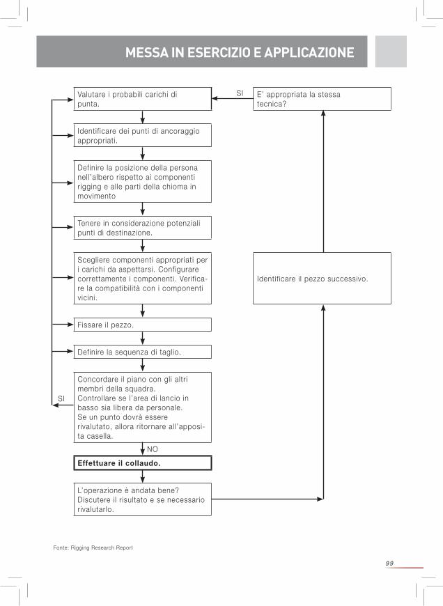
99
MESSA IN ESERCIZIO E APPLICAZIONE
Fonte: Rigging Research Report
Valutare i probabil i carichi di punta.
E’ appropriata la stessa tecnica?
Identif icare dei punti di ancoraggio appropriati.
Definire la posizione della persona nell’albero rispetto ai componenti rigging e alle parti della chioma in movimento
Tenere in considerazione potenziali punti di destinazione.
Scegliere componenti appropriati per i carichi da aspettarsi. Configurare correttamente i componenti. Verif ica-re la compatibil ità con i componenti vicini.
Identif icare i l pezzo successivo.
Fissare i l pezzo.
Definire la sequenza di taglio.
Concordare i l piano con gli altri membri della squadra.Controllare se l’area di lancio in basso sia l ibera da personale.Se un punto dovrà essere rivalutato, allora ritornare all’apposi-ta casella.
Effettuare il collaudo.
L’operazione è andata bene? Discutere i l risultato e se necessario rivalutarlo.
SI
SI
NO
MESSA IN ESERCIZIO E APPLICAZIONE
100
MESSA IN ESERCIZIO E APPLICAZIONE / CONTROLLI REGOLARI
CONTROLLI REGOLARI AVVERTENZE E INDICAZIONI DI SICUREZZA
In generale vale quanto segue: Se per un qualsiasi motivo l’utente – e anche se questo motivo dovesse sembrare a prima vista di minore importanza – non si sente sicuro circa l’ integrità o la conformità del prodotto, dovrà scartarlo e renderlo inutil izzabile oppure metterlo da parte etichettandolo chiaramente in modo tale che non potrà essere uti l izzato erroneamente. Si dovrà riuti l izzarlo solo dopo aver ricevuto una conferma scritta in base ad un esame effettuato da persona esperta.
Una volta subita una sollecitazione d’urto potrà essere necessario sostituire la corda. La capacità della corda di ammortizzare sollecitazioni dinamiche diminuisce durante l’ impiego normale e con sollecitazioni d‘urto. Una corda usata non presenta lo stesso allungamento di una corda nuova, essa non potrà quindi assorbire tanta energia e così aumenterà i l carico di punta. Allo stesso tempo diminuisce il carico di rottura della corda.
Controllare i l prodotto prima e dopo ogni impiego nel modo seguente:Prima e dopo ogni uti l izzo bisogna sottoporre i l prodotto ad un controllo visivo e tattile, per garantirne la completezza, la disponibil ità all’uso e la funzionalità ineccepibile. Controllare la corda da tutte le parti e per tutta la lunghezza. Palpare la corda anche se ap-parentemente sembra intatta per controllare se presenta dei danni invisibil i dell’anima cau-sati eventualmente da eccessive flessioni o sovraccarichi in singoli punti. Badare a punti che evidenziano danni termici (superfici delle corde dall’aspetto vitreo) i l che può essere causato da un attrito elevato all’ interno del sistema. Bisogna prestare particolare attenzione a quella parte della corda che viene usata per realizzare i l mezzo collo semplice sul fusto dell'albero. Di rego-la è questa la parte della corda dove insorgono i danni maggiori. Potrebbe rendersi necessario tagliare questa parte della corda e realizzare una nuova impiombatura oppure uti l izzare l'altra estremità della corda. In caso di dubbio bisogna scartare i l prodotto!
della squadra rispetto a questo pericolo. Assicuratevi che tutti i membri della squadra nonché terzi (non addetti ai lavori) non si trovino nella zona di pericolo. Se una corda viene continuamente girata in una direzione, come per esempio in caso di utilizzo di un verri-cello, bisognerebbe girarla di tanto in tanto nella direzione opposta.
Utilizzo con altri componenti: Bisogna assicurare che siano rispettate le raccomandazioni per l’uso con altri componenti. Assicurate che tutti i componenti siano compatibili, e in particolare Stellen Sie sicher, dass alle Komponenten kompatibel sind, insbesondere bisogna scegliere un rapporto D/d del diametro D del rullo rispetto al diametro d della corda il più grande possibile. Il diametro della scanalatura dev’essere appropriato per il diametro della corda. Assicuratevi che tutti i componenti siano disposti in modo corretto.
Il mancato rispetto aumenta il rischio di lesioni gravi e addirittura mortali.
101
MANUTENZIONE / DURATA DI VITA
Le corde da lavoro Sirius sono provviste di strisce trasversali disposte ad intervall i regolari. Se questo intervallo dovesse iniziare a variare (di regola diventando più grande), si è davanti a un segno di sovraccarico locale. Questo pezzo di corda non dovrà più essere uti l izzato. Sconsigliamo vivamente di utilizzare delle corde che presentino segni di usura. Uti-l izzare esclusivamente corde ineccepibil i che non presentano tagli, nodi o trefoli rotti. Evitare l’attrito della corda strofinandola su superfici ruvide. Badare a che il consumo sia omogeneo. Mai fissare con nodi una corda rotta, si consiglia di scartarla!
Raccomandiamo di fare degli appunti rispetto all’uti l izzo (data, durata, condizioni) e ai controll i effettuati (data, revisore, anomalie). Tenere in considerazione che eventualmente bisogna anche applicare dei Regolamenti nazionali per quanto riguarda gli intervall i di controllo.
Controllare sempre la corda intera, inclusi i giunti terminali e l’hardware! In caso del minimo dubbio bisognerà scartare il prodotto e rispettivamente farlo con-trollare da persona esperta.
Check list: Il controllo deve comprendere i seguenti punti: Controllo dello stato generale: data di produzione, completezza, inquinamento, assemblaggio corretto. Controllo dell’etichetta: l’etichetta è presente e leggibile sì/no, si capisce l’anno di costruzione. Controllo di tutti i particolari se presentano danni meccanici come: tagli, rotture, intagli, abrasioni, deformazioni, formazione di nervature, torsioni / attorcigliamenti non rimediabil i, schiacciamenti, punti induriti. Controllo di tutti i particolari se presentano danneggiamenti termici o chimici come: fusioni, indurimenti, irrigidimenti, alterazioni del colore. Controllo dei componenti metall ici se presentano corrosione e deformazioni. Controllo dello stato e della completezza dei giunti delle estremità, suture (p.es. nessuna abrasione del fi lo di sutura), impiombature (p.es. nessuna separazione), presenza di nodi.
E’ assolutamente indispensabile un controllo regolare dell’attrezzatura. La vostra sicurezza dipende all’efficacia e dalla durata dell’attrezzatura!
Per ulteriori informazioni rimandiamo alla scheda tecnica CI 2001 — Fiber Rope Inspection and Retirement Criteria – dell’Istituto Tauwerk. Da consultare sul sito www.ropecord.com.
I lavori di riparazione dovranno essere eseguiti solo da parte del produttore.
La durata di vita effettiva dipende esclusivamente dallo stato del prodotto, che viene influenza-to da numerosi fattori (vedi sotto). In caso di condizioni estreme può essere ridotta ad un solo uti l izzo o anche meno se l’attrezzatura viene danneggiata ancor prima del primo impiego (p.es. durante i l trasporto).
MANUTENZIONE
DURATA DI VITA
102
TRASPORTO, IMMAGAZZINAMENTO E PULIZIA
I l trasporto dovrà essere eseguito sempre al riparo dalla luce e dalla sporcizia, in un imballag-gio appropriato (di un materiale idrorepellente e impenetrabile alla luce).
Condizioni di immagazzinamento: protetto da raggi UV (luce solare, dispositivi di saldatura..), asciutto e pulito a temperatura ambiente (15 – 25°C), lontano da prodotti chimici (acidi, soluzioni alcaline, l iquidi, vapori, gas...) e altre condizioni aggressive protetto da spigoli taglienti
Immagazzinare i l prodotto quindi in un luogo asciutto e ben ventilato, contenuto in una sacca di materiale idrorepellente e impenetrabile alla luce. Evitare attorcigliamenti della corda!Badare a tenere pulito i l prodotto! La sporcizia penetrata nella corda a causa di strofinamento danneggia la corda. Delle corde umide e sporche possono diventare marce.
Per la pulizia uti l izzare dell’acqua tiepida e un detersivo per tessuti delicati. Successivamente sciacquare l'attrezzatura con acqua pura e asciugarla prima di immagazzinarla. I l prodotto va asciugato in modo naturale, non vicino al fuoco o altri fonti di calore. Per la disinfezione dovranno essere uti l izzate solo sostanze che non hanno nessun influsso sui materiali sintetici uti l izzati.
In caso di mancato rispetto di questa condizione mettete in pericolo la Vostra vita!
TRASPORTO, IMMAGAZZINAMENTO E PULIZIA
La durata di vita è definita fino a 5 anni dalla data di produzione solo in caso di scarso util izzo (1 settimana all‘anno) e di un immagazzinamento a regola d‘arte (vedasi i l punto: Trasporto, im-magazzinamento e pulizia). L’anno di produzione è indicato sull’etichetta. Se non fosse possibi-le identif icare senza alcun dubbio l’anno di produzione del prodotto, bisognerà scartarlo.
L’abrasione meccanica, o altri influssi, come p.es. l’esposizione diretta ai raggi del sole, ne ridurranno notevolmente la durata di vita. Delle fibre scolorate oppure consumate, delle perdite di colore oppure degli irrigidimenti sono un indicatore sicuro del fatto che il prodotto deve es-sere messo fuori servizio. A questo proposito bisogna rispettare le indicazioni di cui al capitolo “Controll i regolari“.
Non è possibile esprimere in modo categorico un’indicazione generica rispetto alla durata di vita del prodotto, dato il fatto che questa è subordinata a diversi fattori, fra cui la esposizione a raggi UV, il tipo e la frequenza d’uso, il trattamento, i fattori climatici come il ghiaccio o la neve, i fattori ambientali come il sale, la sabbia, l'acido delle batterie, ecc., le sollecitazioni termiche (oltre alle condizioni climatiche normali), la deformazione meccanica e / o la formazione di bolle.Controllare sempre la corda intera, inclusi i giunti terminali e l’hardware!
In caso di minimo dubbio bisognerà scartare il prodotto e rispettivamente farlo con-trollare da persona esperta.
103
TRASPORTO, IMMAGAZZINAMENTO E PULIZIA
DICHIARAZIONE DI CONFORMITÀ PER LA CORDA A GRANDE LUNGHEZZA DI TRECCIATO
Denominazione a) Sirius 12 / 14 / 16 / 18 / 20mmb) arborWINCH line 12mm
Funzione Corda per scopi di sollevamento nelle applicazioni di rigging
Modello Vedasi denominazione
Tipo a) Corda intrecciata ad anima e manto in PES / PESb) Corda intrecciata ad anima e manto in HMPE / PES con guaina intermedia in PES.
No. di serie Vedasi etichetta sulla corda a grande lunghezza di trecciato
Denominazione commerciale
Vedasi denominazione
La ditta: TEUFELBERGER Fiber Rope GmbH Vogelweiderstr. 50 A-4600 Welsdichiara con la presente che le macchine di seguito descritte:
sono conformi alle disposizioni del Regolamento sulla sicurezza delle macchine 2010 BGBL. [Gazzetta ufficiale austriaca] 2008_II_282 e quindi alla Direttiva macchine 2006/42/CE nella versione attualmente in vigore.
Wels, l ì 20. gennaio 2016 Wels, l ì 20. gennaio 2016
Responsabilità tecnica Autorizzato al rilascio DI. Rudolf Kirth Rainer Morawa, MBAResponsabile tecnico Fiberrope Amministratore FiberropeTEUFELBERGER Fiber Rope GmbH TEUFELBERGER Fiber Rope GmbHVogelweiderstraße 50 Vogelweiderstraße 50A-4600 Wels A-4600 Wels
DICHIARAZIONE DI CONFORMITÀ
104
Denominazione a) Sta Set ½ / 9/16 / 5/8 / ¾ / 7/8 / 1inchb) tREX 3/8 / 7/16 / ½ / 5/8 / ¾ / 7/8 inchc) Poly Nylon ½ / 9/16 / 5/8 / ¾ / 7/8 / 1 inch
Funzione Corda per scopi di sollevamento nelle applicazioni di rigging
Modello Vedasi denominazione
Tipo a) Corda intrecciata ad anima e manto in PES / PES con involucro di poliuretano b) Intreccio cavo di PES con rivestimento ceratoc) Corda intrecciata ad anima e manto in PA6 / PES
No. di serie Vedasi etichetta sulla corda a grande lunghezza di trecciato
Denominazione commerciale
Vedasi denominazione
La ditta: TEUFELBERGER Fiber Rope Corp. 848 Airport Road Fall River, MA 02720-4735, USAdichiara con la presente che le macchine di seguito descritte:
sono conformi alle disposizioni del Regolamento sulla sicurezza delle macchine 2010 BGBL. [Gazzetta ufficiale austriaca] 2008_II_282 e quindi alla Direttiva macchine 2006/42/CE nella versione attualmente in vigore.
Fall River, 20. gennaio 2016 Fall River, 20. gennaio 2016
Responsabilità tecnica Autorizzato al rilascio John Tedder Chris LavinResponsabile tecnico AmministratoreTEUFELBERGER Fiber Rope Corp. TEUFELBERGER Fiber Rope Corp.848 Airport Road 848 Airport RoadFall River, MA 02720-4735, USA Fall River, MA 02720-4735, USA
DICHIARAZIONE DI CONFORMITÀ
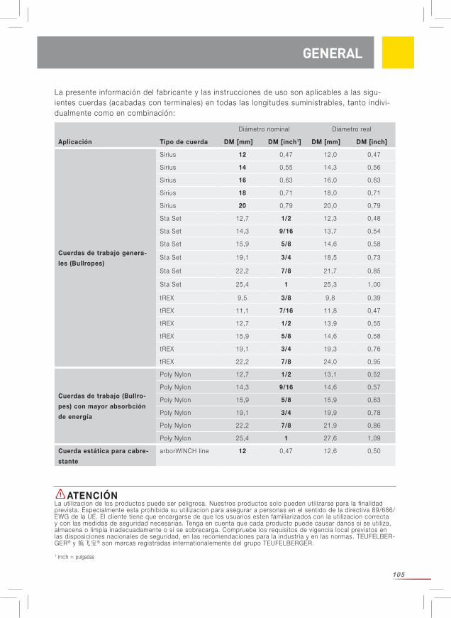
105
La presente información del fabricante y las instrucciones de uso son aplicables a las sigu-ientes cuerdas (acabadas con terminales) en todas las longitudes suministrables, tanto indivi-dualmente como en combinación:
GENERAL
ATENCIÓNLa util izacion de los productos puede ser peligrosa. Nuestros productos solo pueden util izarse para la finalidad prevista. Especialmente esta prohibida su uti l izacion para asegurar a personas en el sentido de la directiva 89/686/EWG de la UE. El cliente tiene que encargarse de que los usuarios esten familiarizados con la uti l izacion correcta y con las medidas de seguridad necesarias. Tenga en cuenta que cada producto puede causar danos si se uti l iza, almacena o limpia inadecuadamente o si se sobrecarga. Compruebe los requisitos de vigencia local previstos en las disposiciones nacionales de seguridad, en las recomendaciones para la industria y en las normas. TEUFELBER-GER® y 拖飞宝® son marcas registradas internationalemente del grupo TEUFELBERGER.
Diámetro nominal Diámetro real
Aplicación Tipo de cuerda DM [mm] DM [inch1] DM [mm] DM [inch]
Cuerdas de trabajo genera-
les (Bullropes)
Sirius 12 0,47 12,0 0,47
Sirius 14 0,55 14,3 0,56
Sirius 16 0,63 16,0 0,63
Sirius 18 0,71 18,0 0,71
Sirius 20 0,79 20,0 0,79
Sta Set 12,7 1/2 12,3 0,48
Sta Set 14,3 9/16 13,7 0,54
Sta Set 15,9 5/8 14,6 0,58
Sta Set 19,1 3/4 18,5 0,73
Sta Set 22,2 7/8 21,7 0,85
Sta Set 25,4 1 25,3 1,00
tREX 9,5 3/8 9,8 0,39
tREX 11,1 7/16 11,8 0,47
tREX 12,7 1/2 13,9 0,55
tREX 15,9 5/8 14,6 0,58
tREX 19,1 3/4 19,3 0,76
tREX 22,2 7/8 24,0 0,95
Cuerdas de trabajo (Bullro-
pes) con mayor absorbción
de energía
Poly Nylon 12,7 1/2 13,1 0,52
Poly Nylon 14,3 9/16 14,6 0,57
Poly Nylon 15,9 5/8 15,9 0,63
Poly Nylon 19,1 3/4 19,9 0,78
Poly Nylon 22,2 7/8 21,9 0,86
Poly Nylon 25,4 1 27,6 1,09
Cuerda estática para cabre-
stante
arborWINCH line 12 0,47 12,6 0,50
1 inch = pulgadas
106
Hay que leer y entender las presentes instrucciones de uso antes de la uti l ización. Siga las recomendaciones y reflexione sobre las condiciones bajo las que quiere uti l izar el producto para ver si es apropiado para ello. ¡Guarde la presente información del fabricante con el producto para poder consultarla posteriormente! Dirí jase al fabricante TEUFELBERGER Fiber Rope GmbH si tie-ne alguna pregunta (los datos de contacto están en el dorso de las presentes instrucciones de uso).
Este producto sólo pueden util izarlo las personas que hayan sido instruidas en su uti l ización segura y que dispongan de los conocimientos y de las facultades corporales y mentales corre-spondientes, o sea, que sean competentes. Los trabajos de apeo controlado conllevan mayor riesgo que la mayor para de las otras actividades de arboricultura. Por ello se necesita también un grado mayor de entrenamiento. Nosotros recomendamos que los usuarios hayan hecho un curso pertinente reconocido de arboricultura como, por ejemplo, ETT (Certif ied European Tree Technician), ETW (Certif ied Europea Tree Worker) o entrenamientos pertinentes de la AA (Arbo-ricultural Association).
Antes de realizar trabajos de apeo controlado hay que comprobar si se necesitan permisos de las autoridades para ello. ¡Delimite y cierre el lugar de trabajo amplia y claramente para que no pueda pasar nadie sin querer a la zona de peligro, especialmente ningún transeúnte! ¡Preste atención por si hay conductos eléctricos u otros potenciales peligros!
¡El incumplimiento de las instrucciones del fabricante, especialmente la inobser-vancia de todas las indicaciones de aviso y de seguridad, puede causar accidentes,
INDICACIONES GENERALES
INDICACIONES GENERALES
Diámetro nominal Diámetro real
Aplicación Tipo de cuerda DM [mm] DM [inch1] DM [mm] DM [inch]
Eslinga Loopie
tREX 9,5 3/8 9,8 0,39
tREX 11,1 7/16 11,8 0,47
tREX 12,7 1/2 13,9 0,55
tREX 15,9 5/8 14,6 0,58
tREX 19,1 3/4 19,3 0,76
tREX 22,2 7/8 24,0 0,95
Eslinge Ploopie (= Eslinga
Loopie + polea PINTO Rig)
tREX 11,1 7/16 11,8 0,47
tREX 12,7 1/2 13,9 0,55
Eslinga con ojo sin guarda-
cabos (un ojo)
tREX 9,5 3/8 9,8 0,39
tREX 11,1 7/16 11,8 0,47
tREX 12,7 1/2 13,9 0,55
tREX 15,9 5/8 14,6 0,58
tREX 19,1 3/4 19,3 0,76
tREX 22,2 7/8 24,0 0,95
107
UTILIZACIÓN SEGÚN FINALIDAD PREVISTA
daños materiales, graves lesiones o incluso la muerte! El peligro de sufrir lesiones y daños materiales es muy alto durante los trabajos de apeo controlado. Cada utiliza-ción que diverja de lo indicado en estas instrucciones y toda inobservancia de estas instrucciones se considerarán como fuera del campo de aplicación definido y, con ello, no aptas para la finalidad o las finalidades definidas.
Elija el equipo de protección individual (EPI) apropiado o legalmente exigido para la finalidad de uso prevista.
¡Respete las normas (nacionales) de seguridad para apeo controlado y para elegir el EPI!
Nosotros consideramos las presentes instrucciones de uso como „trabajo en curso“. Hemos simulado en nuestro centro cargas dinámicas y continuaremos este trabajo con la medición de datos dinámicos. Publicaremos los resultados disponibles en nuestra página web www.teufelberger.com.
Bajo apeo controlado (rigging) se entiende ir bajando un árbol a trozos util izando un sistema de elevación calculado y compuesto por cuerdas texti les, polea y (normalmente) el tronco del árbol como estructura auxil iar natural y que está en condiciones de soportar las fuerzas que surgen al retener los trozos del árbol que pueden tener una gran masa.
La cuerda (acabada con terminales) que acompaña a la presente información del fabricante está concebida exclusivamente para su uso como parte de un sistema para realizar trabajos de apeo controlado. El usuario es el responsable de asegurar la compatibil idad de cada uno de los componentes de un producto con los componentes l imítrofes.
Tenga en cuenta lo siguiente: „Los componentes individuales del sistema actúan recípro-camente en una interacción que todavía no se ha examinado ni comprendido por completo. Durante el apeo controlado sufren los escaladores, el equipo y el propio árbol grandes cargas que son muy difíciles de calcular.“2 Es responsabil idad del usuario estimar y reducir a un míni-mo los riesgos que ello conlleva.
TEUFELBERGER no asume ninguna responsabil idad por consecuencias /daños directos, indi-rectos ni casuales que puedan surgir durante o después del uso del producto y que resulten de una util ización inadecuada incluyendo modificaciones de las cuerdas (hacer un ojo, etc.), combinación deficiente con otros componentes o colocación desfavorable.
Está prohibido util izar los productos de apeo como equipo de protección individual (EPI).
Es importante marcar el equipo de apeo de forma que no pueda confundirse con un EPI ni uti l izarse como tal. Guarda las cuerdas para apeo controlado separadas del restante equipo de ascenso a los árboles
UTILIZACIÓN
2 Fuente: Andreas Detter, „Rigging-Techniken beim Abtragen von Bäumen. Teil 1: Kinematische Analysen“ (Técnicas de apeo controlado al bajar trozos de árboles. Parte 1: análisis cinemáticos) AFZ-Der Wald 24/2008, pág.1322 ss.
108
EXPLICACIÓN DEL MARCADO
Fabricante: TEUFELBERGER Fiber Rope GmbH, Vogelweiderstr. 50, A-4600 WelsTipo Indica el tipo de uso admisible (véase la tabla 1)Sirius, etc. Denominación de la cuerda1 empalme de ojo, etc. Indicación sobre el acabado con terminales (por eje., 1 empalme de ojo)Polyester etc. Material de fibraDM: xx mm Diámetro nominal en [mm] y/o [pulgadas]L: yy m Longitud en [m]xxxxxxx Número de artículo2016-xx Número de serie20zz Año de fabricación03 Mes de fabricación Indicación de que es necesario leer y entender la información del fabricante.
Rated load Los valores de carga expuestos junto a los siguientes símbolos indican la carga nominal en una configuración definida.
EXPLICACIÓN DEL MARCADO
Eslinga Loopie 0°
Eslinge Loopie 90°
Eslinge Soft Eye 0°
Eslinge Soft Eye 90°
Tracción recta
Ojo anudado, tracción recta
Empalme de ojo, tracción recta
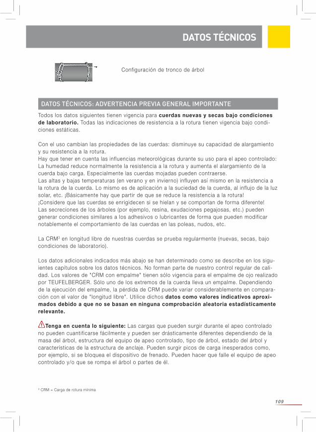
109
Configuración de tronco de árbol
3 CRM = Carga de rotura mínima
DATOS TÉCNICOS
Todos los datos siguientes tienen vigencia para cuerdas nuevas y secas bajo condiciones de laboratorio. Todas las indicaciones de resistencia a la rotura tienen vigencia bajo condi-ciones estáticas.
Con el uso cambian las propiedades de las cuerdas: disminuye su capacidad de alargamiento y su resistencia a la rotura.Hay que tener en cuenta las influencias meteorológicas durante su uso para el apeo controlado: La humedad reduce normalmente la resistencia a la rotura y aumenta el alargamiento de la cuerda bajo carga. Especialmente las cuerdas mojadas pueden contraerse. Las altas y bajas temperaturas (en verano y en invierno) influyen así mismo en la resistencia a la rotura de la cuerda. Lo mismo es de aplicación a la suciedad de la cuerda, al influjo de la luz solar, etc. ¡Básicamente hay que partir de que se reduce la resistencia a la rotura! ¡Considere que las cuerdas se enrigidecen si se hielan y se comportan de forma diferente!Las secreciones de los árboles (por ejemplo, resina, exudaciones pegajosas, etc.) pueden generar condiciones similares a los adhesivos o lubricantes de forma que pueden modificar notablemente el comportamiento de las cuerdas en las poleas, nudos, etc.
La CRM3 en longitud libre de nuestras cuerdas se prueba regularmente (nuevas, secas, bajo condiciones de laboratorio).
Los datos adicionales indicados más abajo se han determinado como se describe en los sigu-ientes capítulos sobre los datos técnicos. No forman parte de nuestro control regular de cali-dad. Los valores de "CRM con empalme" tienen sólo vigencia para el empalme de ojo realizado por TEUFELBERGER. Sólo uno de los extremos de la cuerda lleva un empalme. Dependiendo de la ejecución del empalme, la pérdida de CRM puede variar considerablemente en compara-ción con el valor de "longitud libre". Util ice dichos datos como valores indicativos aproxi-mados debido a que no se basan en ninguna comprobación aleatoria estadísticamente relevante.
Tenga en cuenta lo siguiente: Las cargas que pueden surgir durante el apeo controlado no pueden cuantif icarse fácilmente y pueden ser drásticamente diferentes dependiendo de la masa del árbol, estructura del equipo de apeo controlado, tipo de árbol, estado del árbol y características de la estructura de anclaje. Pueden surgir picos de carga inesperados como, por ejemplo, si se bloquea el dispositivo de frenado. Pueden hacer que falle el equipo de apeo controlado y/o que se rompa el árbol o partes de él.
DATOS TÉCNICOS: ADVERTENCIA PREVIA GENERAL IMPORTANTE
110
DATOS TÉCNICOS
Las siguientes consideraciones (son una pauta aproximada; no se asume ningún tipo de responsabil idad por la corrección de dichas informaciones) se basan únicamente en datos bibliográficos4. La carga en la eslinga de anclaje medida en las pruebas, dependiendo de la colocación y de las circunstancias reales, ha sido de entre 9 y 20 veces mayor que la masa del trozo del árbol5. Véanse los detalles en el informe Rigging Research Report. La carga en la cuerda de trabajo es frecuentemente la mitad de la carga que sufre la eslinga de anclaje. (Atención: ¡Depende en gran medida de la configuración seleccionada!) Según ello, para asegurar que los componentes de la cuerda no se rompan al someterse a cargas por impacto es necesario que la resistencia a la rotura de la eslinga de anclaje en la configuración seleccionada sea entre 9 y 20 veces mayor que la masa del tronco del ár- bol y la resistencia a la rotura de la cuerda de apeo en la configuración seleccionada debe ser mayor que la mitad de la resistencia a la rotura de la eslinga de anclaje. ¡Seleccione, además, un factor de seguridad suficientemente alto!
Pruebas dinámicas realizadas en condiciones realistas, aunque simuladas, en el marco de una tesina patrocinada por Teufelberger y treemagineers arrojan otros valores indicativos (¡Son una pauta aproximada! ¡Sólo un conjunto de condiciones definidas!): Los valores estáticos y dinámicos configurados de la resistencia a la rotura son bastante próximos por lo que los datos de resistencia estática son un buen punto de referencia para definir un l ímite de carga de trabajo (Working Load Limit) aceptable.
¡Tenga en cuenta las advertencias previas generales sobre los datos técnicos, especialmente en lo referente a la relevancia estática!
La indicación de CRM con nudo se aplica a la siguiente colocación: Se ha anudado un ojo a ambos lados util izando un as de guía doble (véase Fig. 1, página 9).
La CRM „en el tronco“ se ha determinado según se expone en las i lustraciones 2-3, página 9.
Informaciones sobre la construcción de la cuerda:
4 Andreas Detter, Chris Cowell et al., „Evaluation of current rigging and dismantling practices used in arboriculture“, Health and Safety Executive Research Report 668, 2008), pág. 234 y ss. (http://www.hse.gov.uk/research/rrpdf/rr668.pdf)5 Lo físicamente correcto sería uti l izar el peso del trozo de árbol en lugar de la masa del trozo de árbol. Se obtiene a partir de la masa [Kg.]*9,81m/s² y es una fuerza en [N]. Simplif icando puede equipararse una masa de 1 Kg. con aprox. 10 N = 1 daN = 0,01 kN.
DATOS TÉCNICOS DE CUERDAS DE TRABAJO/CUERDAS DE APEO BULLROPE
Sirius Sta Set tREX Poly Nylon
NúcleoPoliéster trenzado
Poliéster trenzado Trenzado de
poliéster hueco con recubrimiento
encerado
Polyamide PA6 trenzado
FundaPoliéster trenzado
Poliéster trenzado con recubrimiento
de poliuretano
Poliéster trenzado
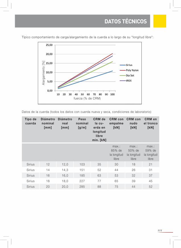
111
Típico comportamiento de carga/alargamiento de la cuerda a lo largo de su "longitud libre":
DATOS TÉCNICOS
Ala
rgam
ient
o [%
]
fuerza (% de CRM)
max.: 85% de
la longitud libre
max.: 50% de
la longitud libre
max.: 59% de
la longitud libre
Sirius 12 12,0 103 35 30 18 21
Sirius 14 14,3 151 52 44 26 31
Sirius 16 16,0 185 63 53 32 37
Sirius 18 18,0 227 77 65 39 45
Sirius 20 20,0 285 88 75 44 52
Tipo de cuerda
Diámetronominal
[mm]
Diámetroreal
[mm]
Peso nominal
[g/m]
CRM de la cu-
erda en longitud
libre min. [kN]
CRM con empalme
[kN]
CRM con nudo [kN]
CRM en el tronco
[kN]
Datos de la cuerda (todos los datos con cuerda nueva y seca, condiciones de laboratorio)
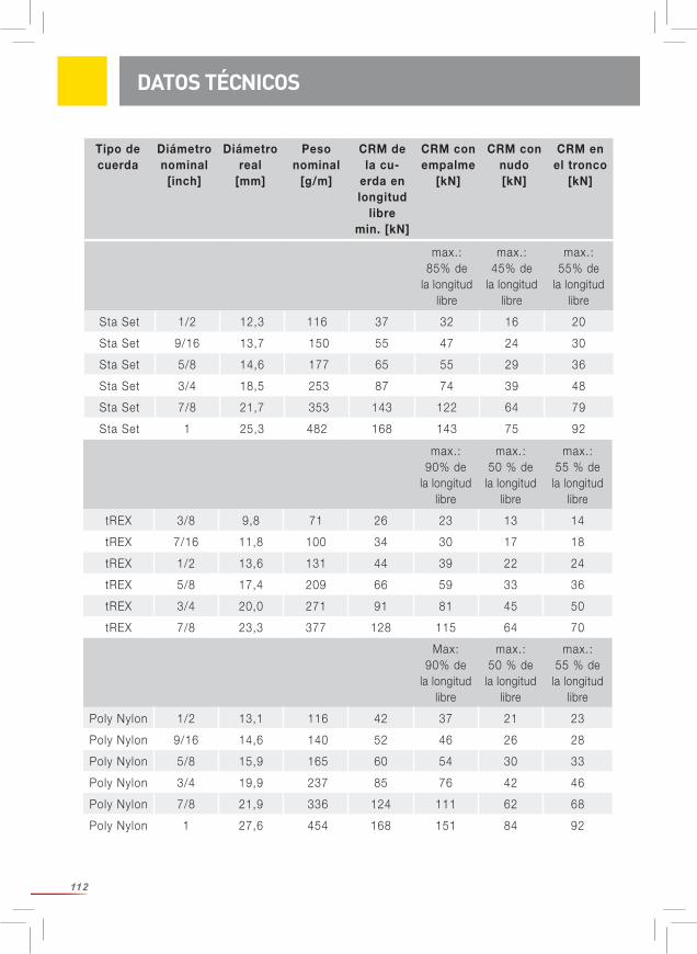
112
DATOS TÉCNICOS
max.: 90% de
la longitud libre
max.: 50 % de
la longitud libre
max.: 55 % de
la longitud libre
tREX 3/8 9,8 71 26 23 13 14
tREX 7/16 11,8 100 34 30 17 18
tREX 1/2 13,6 131 44 39 22 24
tREX 5/8 17,4 209 66 59 33 36
tREX 3/4 20,0 271 91 81 45 50
tREX 7/8 23,3 377 128 115 64 70
Max: 90% de
la longitud libre
max.: 50 % de
la longitud libre
max.: 55 % de
la longitud libre
Poly Nylon 1/2 13,1 116 42 37 21 23
Poly Nylon 9/16 14,6 140 52 46 26 28
Poly Nylon 5/8 15,9 165 60 54 30 33
Poly Nylon 3/4 19,9 237 85 76 42 46
Poly Nylon 7/8 21,9 336 124 111 62 68
Poly Nylon 1 27,6 454 168 151 84 92
max.: 85% de
la longitud libre
max.: 45% de
la longitud libre
max.: 55% de
la longitud libre
Sta Set 1/2 12,3 116 37 32 16 20
Sta Set 9/16 13,7 150 55 47 24 30
Sta Set 5/8 14,6 177 65 55 29 36
Sta Set 3/4 18,5 253 87 74 39 48
Sta Set 7/8 21,7 353 143 122 64 79
Sta Set 1 25,3 482 168 143 75 92
Tipo de cuerda
Diámetronominal
[inch]
Diámetroreal
[mm]
Peso nominal
[g/m]
CRM de la cu-
erda en longitud
libre min. [kN]
CRM con empalme
[kN]
CRM con nudo [kN]
CRM en el tronco
[kN]
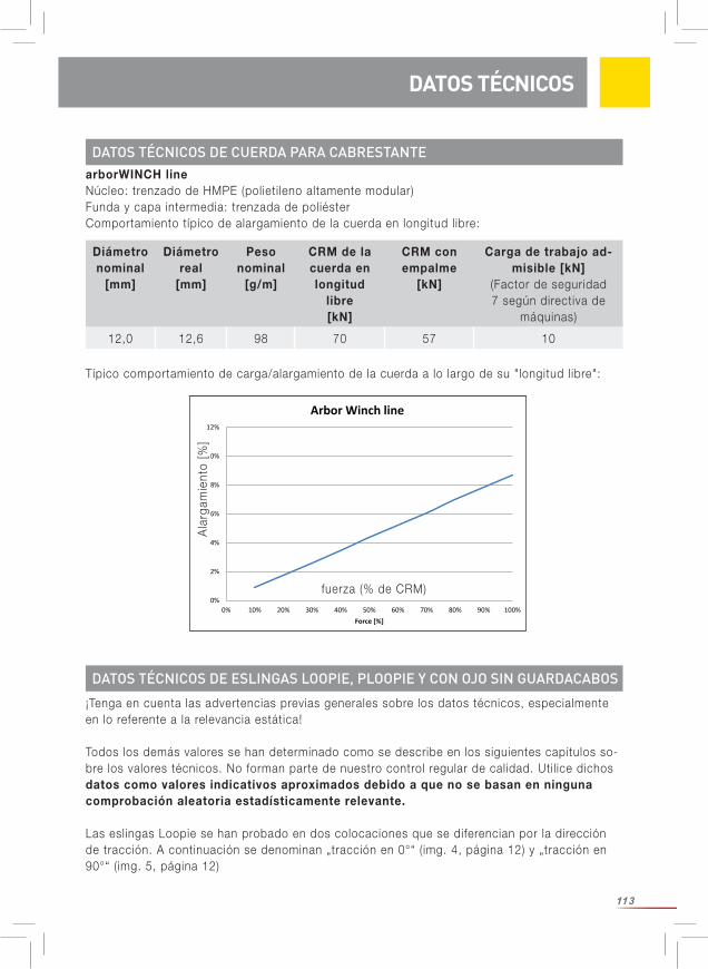
113
DATOS TÉCNICOS DE CUERDA PARA CABRESTANTE
Diámetro nominal
[mm]
Diámetro real
[mm]
Peso nominal
[g/m]
CRM de la cuerda en longitud
libre [kN]
CRM con empalme
[kN]
Carga de trabajo ad-misible [kN]
(Factor de seguridad 7 según directiva de
máquinas)
12,0 12,6 98 70 57 10
¡Tenga en cuenta las advertencias previas generales sobre los datos técnicos, especialmente en lo referente a la relevancia estática!
Todos los demás valores se han determinado como se describe en los siguientes capítulos so-bre los valores técnicos. No forman parte de nuestro control regular de calidad. Util ice dichos datos como valores indicativos aproximados debido a que no se basan en ninguna comprobación aleatoria estadísticamente relevante.
Las eslingas Loopie se han probado en dos colocaciones que se diferencian por la dirección de tracción. A continuación se denominan „tracción en 0°“ (img. 4, página 12) y „tracción en 90°“ (img. 5, página 12)
0%
2%
4%
6%
8%
10%
12%
0% 10% 20% 30% 40% 50% 60% 70% 80% 90% 100%
Elon
gatio
n [%
]
Force [%]
Arbor Winch line
arborWINCH lineNúcleo: trenzado de HMPE (polieti leno altamente modular)Funda y capa intermedia: trenzada de poliésterComportamiento típico de alargamiento de la cuerda en longitud libre:
DATOS TÉCNICOS DE ESLINGAS LOOPIE, PLOOPIE Y CON OJO SIN GUARDACABOS
DATOS TÉCNICOS
Ala
rgam
ient
o [%
]
fuerza (% de CRM)
Típico comportamiento de carga/alargamiento de la cuerda a lo largo de su "longitud libre":
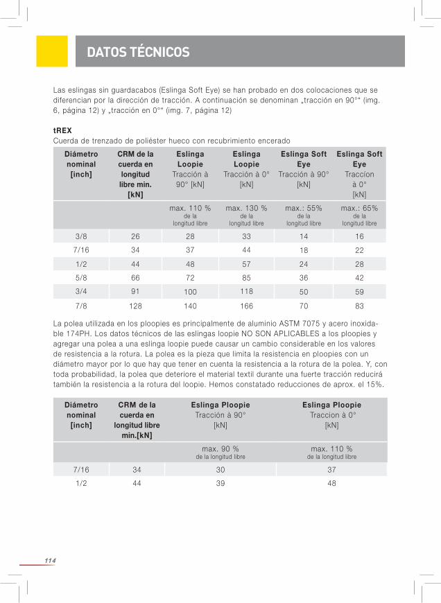
114
Las eslingas sin guardacabos (Eslinga Soft Eye) se han probado en dos colocaciones que se diferencian por la dirección de tracción. A continuación se denominan „tracción en 90°“ (img. 6, página 12) y „tracción en 0°“ (img. 7, página 12)
tREXCuerda de trenzado de poliéster hueco con recubrimiento encerado
DATOS TÉCNICOS
Diámetro nominal [inch]
CRM de la cuerda en longitud libre min.
[kN]
Eslinga Loopie
Tracción à 90° [kN]
Eslinga Loopie
Tracción à 0°[kN]
Eslinga Soft Eye
Tracción à 90°[kN]
Eslinga Soft Eye
Traccíon à 0°[kN]
max. 110 % de la
longitud libre
max. 130 % de la
longitud libre
max.: 55%de la
longitud libre
max.: 65% de la
longitud libre
3/8 26 28 33 14 16
7/16 34 37 44 18 22
1/2 44 48 57 24 28
5/8 66 72 85 36 42
3/4 91 100 118 50 59
7/8 128 140 166 70 83
Diámetro nominal [inch]
CRM de la cuerda en
longitud libre min.[kN]
Eslinga PloopieTracción à 90°
[kN]
Eslinga Ploopie Traccion à 0°
[kN]
max. 90 % de la longitud libre
max. 110 % de la longitud libre
7/16 34 30 37
1/2 44 39 48
La polea uti l izada en los ploopies es principalmente de aluminio ASTM 7075 y acero inoxida-ble 174PH. Los datos técnicos de las eslingas loopie NO SON APLICABLES a los ploopies y agregar una polea a una eslinga loopie puede causar un cambio considerable en los valores de resistencia a la rotura. La polea es la pieza que limita la resistencia en ploopies con un diámetro mayor por lo que hay que tener en cuenta la resistencia a la rotura de la polea. Y, con toda probabil idad, la polea que deteriore el material texti l durante una fuerte tracción reducirá también la resistencia a la rotura del loopie. Hemos constatado reducciones de aprox. el 15%.
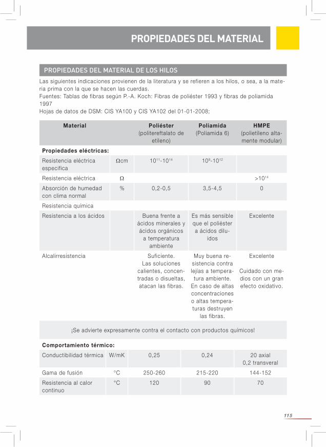
115
PROPIEDADES DEL MATERIAL DE LOS HILOS
PROPIEDADES DEL MATERIAL
Material Poliéster (politereftalato de
eti leno)
Poliamida(Poliamida 6)
HMPE(polieti leno alta-mente modular)
Propiedades eléctricas:
Resistencia eléctrica especifica
Ωcm 1011-1014 109-1012
Resistencia eléctrica Ω >1014
Absorción de humedad con clima normal
% 0,2-0,5 3,5-4,5 0
Resistencia química
Resistencia a los ácidos Buena frente a ácidos minerales y ácidos orgánicos
a temperatura ambiente
Es más sensible que el poliéster a ácidos dilu-
idos
Excelente
Alcalirresistencia Suficiente. Las soluciones
calientes, concen-tradas o disueltas, atacan las fibras.
Muy buena re-sistencia contra lejías a tempera-tura ambiente.
En caso de altas concentraciones o altas tempera-turas destruyen
las fibras.
Excelente
Cuidado con me-dios con un gran efecto oxidativo.
¡Se advierte expresamente contra el contacto con productos químicos!
Las siguientes indicaciones provienen de la l iteratura y se refieren a los hilos, o sea, a la mate-ria prima con la que se hacen las cuerdas. Fuentes: Tablas de fibras según P.-A. Koch: Fibras de poliéster 1993 y fibras de poliamida 1997 Hojas de datos de DSM: CIS YA100 y CIS YA102 del 01-01-2008;
Comportamiento térmico:
Conductibil idad térmica W/mK 0,25 0,24 20 axial0,2 transveral
Gama de fusión °C 250-260 215-220 144-152
Resistencia al calor continuo
°C 120 90 70
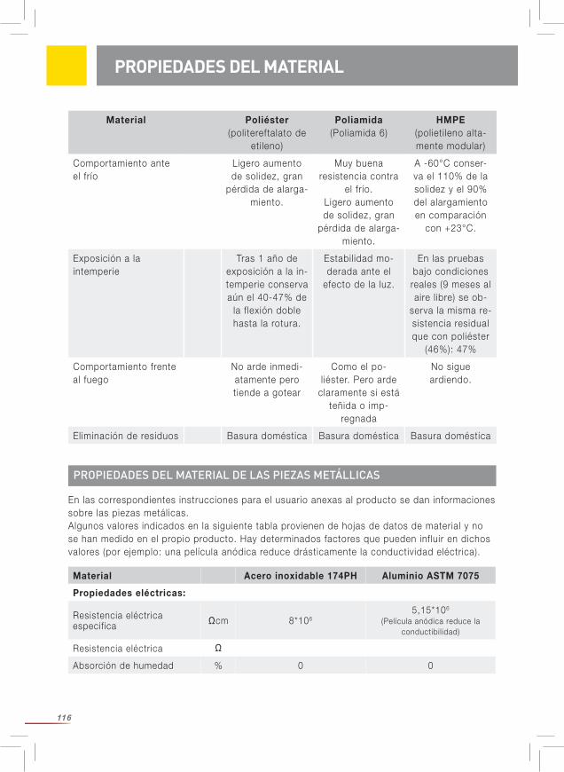
116
Material Poliéster (politereftalato de
eti leno)
Poliamida(Poliamida 6)
HMPE(polieti leno alta-mente modular)
Comportamiento ante el frío
Ligero aumento de solidez, gran
pérdida de alarga-miento.
Muy buena resistencia contra
el frío. Ligero aumento de solidez, gran
pérdida de alarga-miento.
A -60°C conser-va el 110% de la solidez y el 90% del alargamiento en comparación
con +23°C.
Exposición a la intemperie
Tras 1 año de exposición a la in-temperie conserva aún el 40-47% de
la flexión doble hasta la rotura.
Estabil idad mo-derada ante el
efecto de la luz.
En las pruebas bajo condiciones reales (9 meses al aire l ibre) se ob-
serva la misma re-sistencia residual que con poliéster
(46%): 47%
Comportamiento frente al fuego
No arde inmedi-atamente pero tiende a gotear
Como el po-liéster. Pero arde
claramente si está teñida o imp-
regnada
No sigue ardiendo.
Eliminación de residuos Basura doméstica Basura doméstica Basura doméstica
PROPIEDADES DEL MATERIAL
PROPIEDADES DEL MATERIAL DE LAS PIEZAS METÁLLICAS
En las correspondientes instrucciones para el usuario anexas al producto se dan informaciones sobre las piezas metálicas.Algunos valores indicados en la siguiente tabla provienen de hojas de datos de material y no se han medido en el propio producto. Hay determinados factores que pueden influir en dichos valores (por ejemplo: una película anódica reduce drásticamente la conductividad eléctrica).
Material Acero inoxidable 174PH Aluminio ASTM 7075
Propiedades eléctricas:
Resistencia eléctrica especifica Ωcm 8*106
5,15*106
(Película anódica reduce la conductibil idad)
Resistencia eléctrica Ω
Absorción de humedad % 0 0
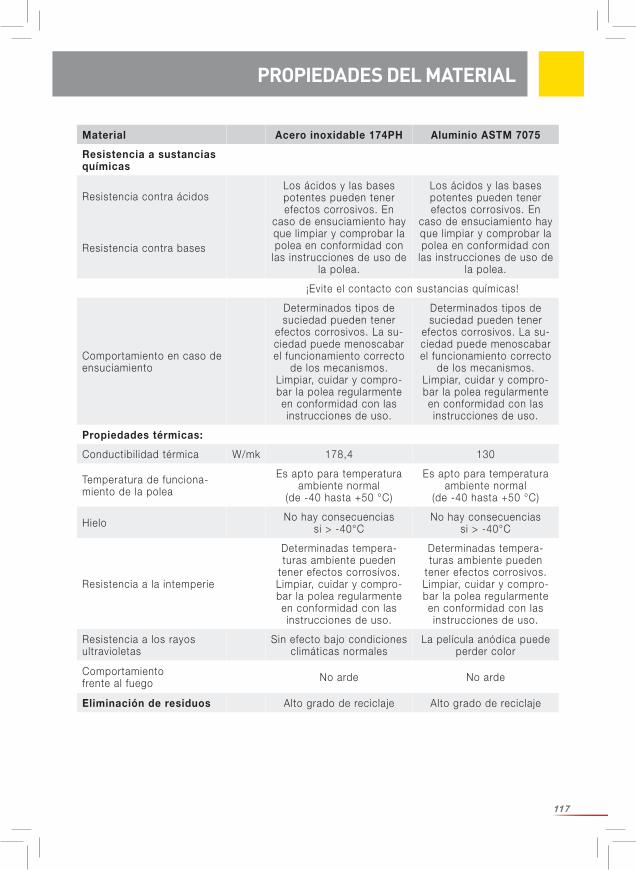
117
PROPIEDADES DEL MATERIAL PROPIEDADES DEL MATERIAL
Material Acero inoxidable 174PH Aluminio ASTM 7075
Resistencia a sustancias químicas
Resistencia contra ácidosLos ácidos y las bases potentes pueden tener efectos corrosivos. En
caso de ensuciamiento hay que limpiar y comprobar la polea en conformidad con
las instrucciones de uso de la polea.
Los ácidos y las bases potentes pueden tener efectos corrosivos. En
caso de ensuciamiento hay que limpiar y comprobar la polea en conformidad con
las instrucciones de uso de la polea.
Resistencia contra bases
¡Evite el contacto con sustancias químicas!
Comportamiento en caso de ensuciamiento
Determinados tipos de suciedad pueden tener
efectos corrosivos. La su-ciedad puede menoscabar el funcionamiento correcto
de los mecanismos.Limpiar, cuidar y compro-bar la polea regularmente en conformidad con las instrucciones de uso.
Determinados tipos de suciedad pueden tener
efectos corrosivos. La su-ciedad puede menoscabar el funcionamiento correcto
de los mecanismos.Limpiar, cuidar y compro-bar la polea regularmente en conformidad con las instrucciones de uso.
Propiedades térmicas:
Conductibil idad térmica W/mk 178,4 130
Temperatura de funciona-miento de la polea
Es apto para temperatura ambiente normal
(de -40 hasta +50 °C)
Es apto para temperatura ambiente normal
(de -40 hasta +50 °C)
Hielo No hay consecuencias si > -40°C
No hay consecuencias si > -40°C
Resistencia a la intemperie
Determinadas tempera-turas ambiente pueden
tener efectos corrosivos. Limpiar, cuidar y compro-bar la polea regularmente en conformidad con las instrucciones de uso.
Determinadas tempera-turas ambiente pueden
tener efectos corrosivos. Limpiar, cuidar y compro-bar la polea regularmente en conformidad con las instrucciones de uso.
Resistencia a los rayos ultravioletas
Sin efecto bajo condiciones climáticas normales
La película anódica puede perder color
Comportamiento frente al fuego No arde No arde
Eliminación de residuos Alto grado de reciclaje Alto grado de reciclaje
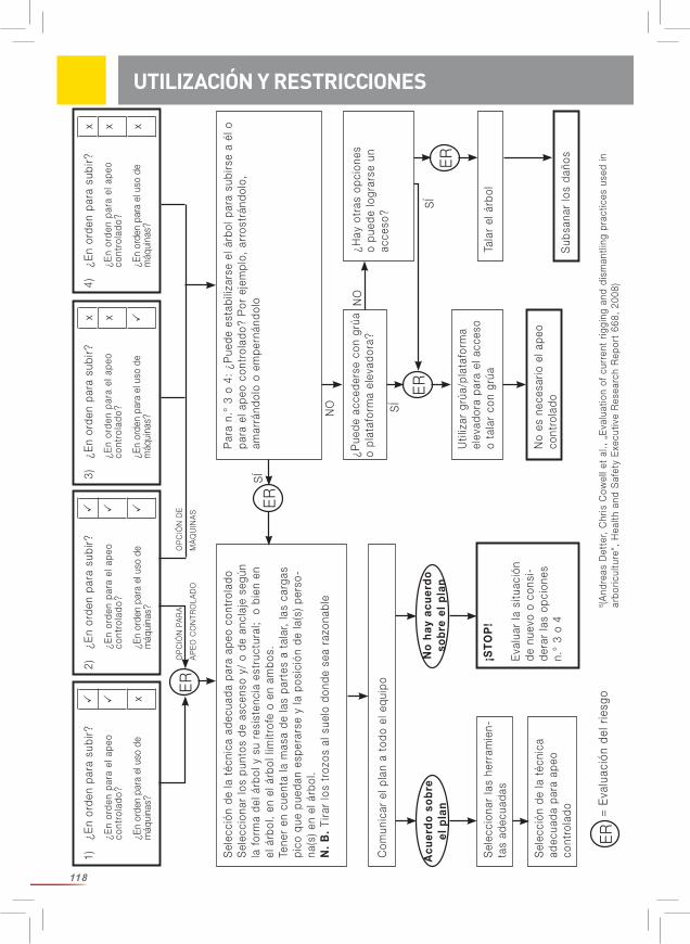
118
1)¿E
n or
den
para
sub
ir?
¿En
orde
n pa
ra e
l ape
o co
ntro
lado
?
¿En
orde
n pa
ra e
l uso
de
máq
uina
s?
x
Sel
ecci
ón d
e la
téc
nica
ade
cuad
a pa
ra a
peo
cont
rola
doS
elec
cion
ar lo
s pu
ntos
de
asce
nso
y/ o
de
ancl
aje
segú
n la
for
ma
del á
rbol
y s
u re
sist
enci
a es
truc
tura
l; o
bie
n en
el
árb
ol,
en e
l árb
ol li
mítr
ofe
o en
am
bos.
Tene
r en
cue
nta
la m
asa
de la
s pa
rtes
a t
alar
, la
s ca
rgas
pi
co q
ue p
ueda
n es
pera
rse
y la
pos
ició
n de
la(s
) pe
rso -
na(s
) en
el á
rbol
.N
. B
. Ti
rar
los
troz
os a
l sue
lo d
onde
sea
raz
onab
le
Par
a n.
° 3
o 4:
¿P
uede
est
abili
zars
e el
árb
ol p
ara
subi
rse
a él
o
para
el a
peo
cont
rola
do?
Por
eje
mpl
o, a
rros
trán
dolo
, am
arrá
ndol
o o
empe
rnán
dolo
Com
unic
ar e
l pla
n a
todo
el e
quip
o
¿Pue
de a
cced
erse
con
grú
a o
plat
afor
ma
elev
ador
a?¿H
ay o
tras
opc
ione
s o
pued
e lo
grar
se u
n ac
ceso
?
Util
izar
grú
a/pl
ataf
orm
a el
evad
ora
para
el a
cces
o o
tala
r co
n gr
úaTa
lar
el á
rbol
No
es n
eces
ario
el a
peo
cont
rola
do
Sel
ecci
onar
las
herr
amie
n-ta
s ad
ecua
das
¡ST
OP
!
Eva
luar
la s
ituac
ión
de n
uevo
o c
onsi
-de
rar
las
opci
ones
n.
° 3
o 4
Acu
erd
o s
ob
re
el p
lan
No
hay
acu
erd
o so
bre
el
pla
n
ER
SÍ
SÍ
SÍ
NO
NO
OP
CIÓ
N D
E
MÁ
QU
INA
S
OP
CIÓ
N P
AR
A
AP
EO
CO
NTR
OLA
DO
=
Eva
luac
ión
del r
iesg
o
Sub
sana
r lo
s da
ños
Sel
ecci
ón d
e la
téc
nica
ad
ecua
da p
ara
apeo
co
ntro
lado
ER
ER
ER
ER
8 (A
ndre
as D
ette
r, C
hris
Cow
ell e
t al
., „
Eva
luat
ion
of c
urre
nt r
iggi
ng a
nd d
ism
antli
ng p
ract
ices
use
d in
ar
boric
ultu
re“,
Hea
lth a
nd S
afet
y E
xecu
tive
Res
earc
h R
epor
t 66
8, 2
008)
UTILIZACIÓN Y RESTRICCIONES2)
¿En
orde
n pa
ra s
ubir?
¿En
orde
n pa
ra e
l ape
o co
ntro
lado
?
¿En
orde
n pa
ra e
l uso
de
máq
uina
s?
3)¿E
n or
den
para
sub
ir?
x
¿En
orde
n pa
ra e
l ape
o co
ntro
lado
? x
¿En
orde
n pa
ra e
l uso
de
máq
uina
s?
4)¿E
n or
den
para
sub
ir?
x
¿En
orde
n pa
ra e
l ape
o co
ntro
lado
? x
¿En
orde
n pa
ra e
l uso
de
máq
uina
s?
x
119
A OBSERVAR ANTES DEL USOAntes de realizar trabajos de apeo controlado: Haga un análisis exacto de riesgos. El usuario es responsable de que haya una evaluación de riesgos relevante y „actual“ para los trabajos a realizar que también incluya casos de emergencia. Especialmente es necesario hacer un control visual meticuloso del árbol. Planifique y organice cada uno de los pasos. Tenga en cuenta que las partes individuales del mismo árbol tienen comportamientos diferentes. Por ello puede ser necesario tener que aplicar medidas y técnicas diferentes para diferentes partes del árbol El apeo controlado es normalmente un trabajo en equipo. Encárguese de que cada miembro del equipo conozca su ámbito de responsabil idad. Establezca una comunicación clara entre los participantes acordando indicaciones de voz o señales con la mano inequívocas, eventualmente también util izando un sistema de radio o similares. Está terminantemente prohibida la estancia bajo cargas en suspensión (¡peligro de muerte!). Asimismo hay que tener en cuenta que el viento puede desviar claramente la curva de caída de un trozo del árbol o hacer girar las ramas en suspensión o desviarlas de la dirección axial.¡Delimite y cierre con la suficiente amplitud el espacio l ibre y l imite el acceso para que no pueda pasar nadie sin querer a la zona de peligro, especialmente ningún transeúnte! Reduzca los riesgos a un mínimo y aplique medidas para evitar accidentes. Antes de uti l izar el producto hay que disponer de un plan con medidas de rescate que tenga en cuenta todos los casos de emergencia imaginables. Hay que pensar antes y durante el uso del producto la forma en que pueden aplicarse las medidas de rescate con seguridad y eficacia. Hay que analizar en todo caso la posición de cada uno de los participantes. Determine los factores de seguridad. ¡Eli ja la técnica de apeo controlado más segura para cada caso de aplicación! Eli ja luego el equipo de apeo controlado adecuado y con la configuración apropiada para ello. ¡Tome todas las medidas necesarias para la seguridad del escalador! ¡Util ice el equipo de protección individual necesario para la protección contra caídas (EPI)! El escalador y su EPI –o sea, el sistema que le asegura– tienen que estar fuera de la curva de caída que describa el trozo de árbol a apear y el equipo de apeo controlado. Por favor, tenga siempre en cuenta que si se rompe la cuerda, ésta puede retroceder bruscamente arrastrando hacia arriba los elementos físicos de la cuerda en el árbol Una situación realmente crítica se da cuando el trozo del árbol choca contra el tronco haci- endo que el árbol se ponga a oscilar. El equipo personal tiene que evaluar los efectos de la
UTILIZACIÒN Y RESTRICCIONES / SEGURIDAD
UTILIZACIÓN Y RESTRICCIONES
Antes de util izar cuerdas para apeo controlado hay que pensar si el apeo controlado es el método más apropiado. Considere si es seguro subir al árbol y si es seguro aplicar el método del apeo controlado en ese árbol. El apeo controlado sólo es conveniente si puede responder a ambas preguntas con „sí“. Considere también si no es más seguro uti l izar máquinas (grúa, plataforma de trabajo o similares) en lugar del apeo controlado.
120
fuerzas resultantes sobre la estructura de anclaje del escalador o de los escaladores y tomar medidas para reducir el riesgo a un grado aceptable. El escalador tiene que prever una posibil idad de abandonar el árbol antes de realizar los trabajos de tala y de apeo controlado. El escalador debería l levar consigo una sierra de mano. Sea consciente de toda la responsabil idad que conllevan los trabajos previstos. Una persona competente tiene que asumir la responsabil idad de la planificación de todos los trabajos de apeo controlado
Tenga en cuenta lo siguiente: Las cargas que pueden surgir durante el apeo controlado no pueden cuantif icarse fácilmente y pueden ser drásticamente diferentes dependiendo de la masa del árbol, estructura del equipo de apeo controlado, tipo de árbol, estado del árbol y forma de la estructura de anclaje. Pueden surgir picos de carga inesperados como, por ejem-plo, si se bloquea el dispositivo de frenado. Pueden hacer que falle el equipo de apeo contro-lado y/o que se rompa el árbol o partes de él.
En la l iteratura6 se describen curvas de caída de tipo ideal. ¡Atención! ¡En la práctica hay que esperar que haya divergencias!
6 Andreas Detter, Chris Cowell et al., „Evaluation of current rigging and dismantling practices used in arboriculture“, Health and Safety Executive Research Report 668, 2008
SEGURIDAD
0,00,0
0,5 1,0
0,5
1,0
1,5
2,0
altu
ra d
e ca
ída
vert
ical
en
[met
ros]
distancia horizontal en [metros]
La parte del árbol se inclina y comienza a caer
La fuerza máxima se produce en la sección del cable que está conectado a la parte del árbol que cae.
trayectoria de centroide
121
SELECCIÓN
Antes de montar un sistema de apeo controlado hay que realizar un análisis de riesgos especial para el lugar de trabajo previsto. Determine cómo se va a colocar cada uno de los componentes. La capacidad de cada uno de los componentes tiene que armonizar con la de los demás. Consulte para ello la resistencia de la configuración seleccionada. El control visual del árbol es un paso de trabajo de importancia básica. Reflexione sobre las cargas que puedan generarse en el peor de los casos durante el apeo controlado y considere los daños no visibles que tenga el árbol.
En el capítulo "Datos técnicos" se indica la capacidad técnica de las cuerdas secas y nuevas bajo condiciones de laboratorio. Considere usted si es suficiente para su aplicación.
Tenga en cuenta lo siguiente: Las cargas dinámicas generan fuerzas considerablemente mayores que las cargas estáticas. La unión de las puntas de las cuerdas tiene menor resistencia a la rotura que la cuerda en longitud libre. (Los nudos reducen considerablemente la resistencia a la rotura de la cuerda. Es incluso posible que la reducción supere el 50%. Si los empalmes se hacen correctamente puede partirse de una reducción con una magnitud de entre el 10 y el 20%.) La colocación de las cuerdas y eslingas puede influir considerablemente en las fuerzas que actúan sobre ellas. En el sentido de la seguridad hay que partir siempre del peor de los casos („escenario más desfavorable“) siendo necesario tener en cuenta incidentes imprevistos.
Las cargas dinámicas se generan cuando una carga descendiente/oscilante cae en el sistema de apeo controlado. Cuanto más rápido o abrupto se absorba la carga tanto mayor será la car-ga dinámica. En dichos casos, la carga dinámica puede equivaler fácilmente a muchas veces la carga estática. Debería planificar su trabajo de forma que se eviten y/o controlen las cargas dinámicas. Tenga en cuenta la capacidad de carga de la eslinga de anclaje debido a que las fuerzas ejercidas pueden superar en más del doble a las fuerzas que actúan en la cuerda de apeo controlado.
Es necesario que en el lugar de trabajo esté presente una persona competente formada en el cálculo de las fuerzas activas y que conozca las relaciones existentes entre la masa del trozo de árbol, altura de caída, tipo de cuerda, longitud de cuerda y otras magnitudes rele-vantes para dirigir los trabajos de apeo controlado.
Se ha constatado en investigaciones7 que la carga en la eslinga de anclaje es aproxima-damente entre 9 y 20 veces superior a la masa del trozo de árbol. ¡Atención! ¡Se trata sólo de un punto de referencia!
¡Asegúrese de que las propiedades de la cuerda son adecuadas para la correspondiente aplicación!
Aplique un factor de seguridad adecuado. Por favor, véa las recomendaciones para seleccionar
7 Brian Kane et al., „Forces and Stresses Generated During Rigging Operations“, Arboriculture & Forestry 2009, 35(2), 68-74.
SELECCIÓN
122
el factor de seguridad en la hoja informativa „International Guidelines on the Safer Use of Fiber Rope“ (CI 1401) del Tauwerk Institut (Instituto de Cordaje). Acceso gratuito bajo www.ropecord.com. En la directiva 2006/42/CE relativa a las máquinas se recomienda un factor de seguridad de al menos 7 (relación entre la resistencia a la rotura de una cuerda nueva sin empalmes ni lazos y la carga estática de trabajo) para tareas de elevación. Además, en la l iteratura se propone multiplicar todas las cargas estimadas por un factor de 1,58.
Tenga en cuenta que la capacidad de carga de su sistema equivale a la del componente más débil.
Desenrollar un carrete (Fig. 8, página 19)Cuando se quite la cuerda de un carrete, éste debería poder girar l ibremente. Ello se logra introduciendo una barra por el centro del carrete y tirando de la cuerda mientras el carrete gira. No quite nunca la cuerda de un carrete que esté echado a un lado porque la cuerda se retuerce.
Desenrollar de un rollo:Para desenrollar la cuerda de un rollo debería comenzarse con el extremo interior. La cuerda debería desenrollarse en el sentido opuesto al de las agujas del reloj. Si se saca la cuerda en el sentido de las agujas del reloj se forman nudos. Vuelva a enrollar en dicho caso la cuerda, de la vuelta al rollo y saque la cuerda del centro. La cuerda debería salir ahora en el sentido opuesto al de las agujas del reloj y sin nudos.
Nudos:
Tenga en cuenta que cada nudo reduce considerablemente la resistencia a la rotura. En nuestras mediciones se ha uti l izado el as de guía doble.
Instrucciones para el as de guía doble (Img. 9 - 13, página 20)
Empalme:
Tenga que cuenta que cada empalme reduce la resistencia a la rotura. ¡Sólo debe hacer usted mismo un empalme si está entrenado en ello!Las instrucciones de los empalmes para Sirius, Poly Nylon, Sta Set, arborWINCH line y tRex están disponibles para su descarga en nuestra página web: www.teufelberger.com.No asumimos ningún tipo de responsabil idad por empalmes ni por otros lazos o terminales en las cuerdas que no las haya hecho TEUFELBERGER.
Eslinga Loopie / Ploopie: Ponga la polea en la eslinga Loopie y extienda cuidadosamente el empalme. (Img. 14-15, página 20)
PUESTA EN SERVICIO Y UTILIZACIÓN
8 Andreas Detter, Chris Cowell et al., „Evaluation of current rigging and dismantling practices used in arboriculture“, Health and Safety Executive Research Report 668, 2008
PUESTA EN SERVICIO Y UTILIZACIÓN
123
Rodee el árbol y pase la polea por la eslinga Loopie. Puede ajustar la longitud de la eslinga Loopie: Apriete la eslinga y compruebe si ésta y la polea tienen una buena sujeción. (Img. 16 - 18, página 21)
Eslinga sin guardacabos (Soft Eye): Coloque el ojo con la polea alrededor del árbol como se expone en las siguientes imágenes. La punta rígida de la cuerda facil ita el enhebrado. (Img. 19 - 24, página 21)
Introduzca la punta suelta entre la eslinga y el árbol de forma que quede fija. (Img. 25, página 22)
Monte ahora la cuerda de trabajo con un as de guía doble como se explica más detalla-damente en el capítulo de los datos técnicos. (Img. 26 - 29, página 22)
¡Revise el sistema después del montaje! ¡Mantenga la cuerda alejada de objetos / superficies abrasivas o con aristas vivas! La siguiente i lustración (página 122) puede ayudarle a realizar con seguridad los trabajos de apeo controlado.
PUESTA EN SERVICIO Y UTILIZACIÓN
Para minimizar las fuerzas que surgen: Reduzca la masa del trozo de árbol Reduzca la longitud del trozo de árbol Ponga el bloque lo más próximo posible al punto de intersección Ponga la polea por encima del punto de intersección (en el mismo árbol o en árboles / estructuras l imítrofes) Evite que la cuerda de apeo Bullrope se combe.
ATENCIÓN: Éstas son sólo recomendaciones esenciales. En un caso concreto puede ha-ber motivos para no aplicar estos principios.
¡Reduzca los movimientos pendulares todo lo que sea posible!
¡Retorcer la cuerda (respecto al eje longitudinal) reduce la vida úti l! El dibujo en la funda de las cuerdas Sirius ayuda a detectar los retorcimientos.
Las cuerdas con mayor alargamiento pueden absorber más energía. Todas las cuerdas se dilatan, una cuerda larga más que una corta. Cuanto más carga se aplique tanto más se alarga la cuerda.¡Pero tenga en cuenta que el alargamiento significa peligro! Una cuerda dilatada puede mover también la carga de una forma imprevista o peligrosa. Una cuerda dilatada puede retroceder con un latigazo y causar así lesiones serias. ¡No enrolle jamás la cuerda alrededor de su mano ni de su cuerpo! Asegúrese de que no pisa las cuerdas de apeo controlado mientras se estén realizando los trabajos de apeo. Mantenga alejadas las ramas, herramientas y otros objetos de las cuerdas de apeo controlado que se muevan rápidamente. ¡Tenga en cuenta que la altura de caída aumenta con el alargamiento de la cuerda! El uso de cuer-das con mayor alargamiento puede dificultar el control sobre la parte del árbol cortada.
A tener en cuenta, especialmente si se usa un cabrestante: Evite ponerse directamente en el trayecto de tracción. En caso de una alta carga de tracción,
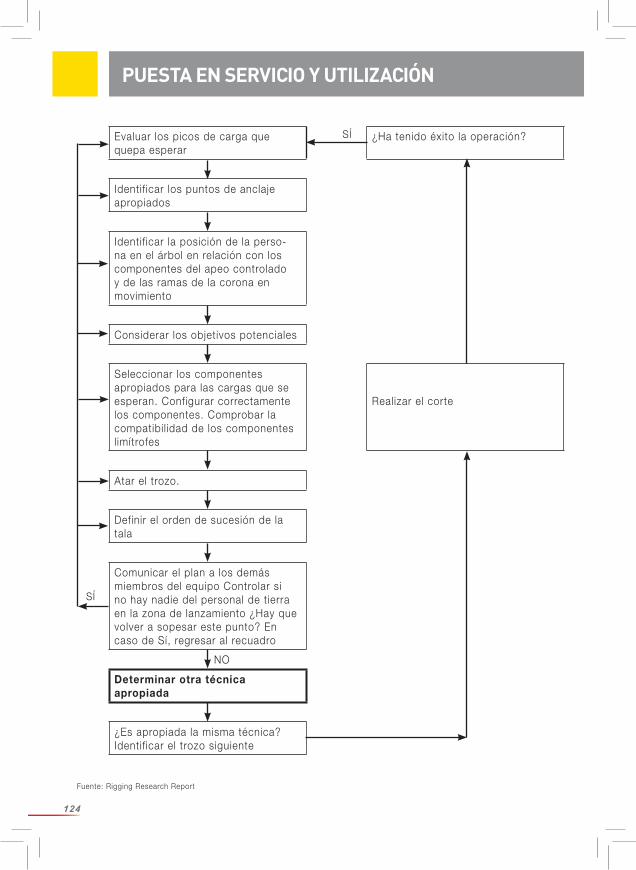
124
Fuente: Rigging Research Report
PUESTA EN SERVICIO Y UTILIZACIÓN
Evaluar los picos de carga que quepa esperar
¿Ha tenido éxito la operación?
Identif icar los puntos de anclaje apropiados
Identif icar la posición de la perso-na en el árbol en relación con los componentes del apeo controlado y de las ramas de la corona en movimiento
Considerar los objetivos potenciales
Seleccionar los componentes apropiados para las cargas que se esperan. Configurar correctamente los componentes. Comprobar la compatibil idad de los componentes l imítrofes
Realizar el corte
Atar el trozo.
Definir el orden de sucesión de la tala
Comunicar el plan a los demás miembros del equipo Controlar si no hay nadie del personal de tierra en la zona de lanzamiento ¿Hay que volver a sopesar este punto? En caso de Sí, regresar al recuadro
Determinar otra técnica apropiada
¿Es apropiada la misma técnica?Identif icar el trozo siguiente
SÍ
SÍ
NO
125
VERIFICACIÓN REGULAR
la elasticidad del material sintético genera una energía enorme que se libera en caso de rotura de la cuerda con lo que existe un máximo peligro (de muerte). Existe peligro en el caso de que haya personas en el trayecto de la cuerda y ésta tenga una tensión excesiva. Si la cuerda se rompe da un latigazo con una fuerza considerable. Ello puede causar graves lesiones que incluso pueden resultar mortales. Informe de este peligro a todos los miembros del equipo. Asegúrese de que no haya ningún empleado ni nadie ajeno en la zona de peligro. En el caso de que la cuerda gire continuamente en una dirección como, por ejemplo, si se usa con un cabestrante entonces debería girarse ocasionalmente en la dirección opuesta.
Utilización con otros componentes: Hay que asegurarse de que se respetan las recomendaciones para el uso con otros componentes.
Asegúrese de que todos los componentes son compatibles, especialmente: Hay que elegir la relación D/d entre el diámetro de la polea (D) y el diámetro de la cuerda (d) lo más grande posible. El diámetro de la garganta tiene que ser adecuado para el diámetro de la cuerda Asegúrese de que todos los componentes están colocados correctamente.
Si no se hace, aumenta el riesgo de sufrir lesiones graves o incluso mortales.
VERIFICACIÓN REGULAR
ADVERTENCIA/INDICACIONES DE SEGURIDAD
En general se aplica lo siguiente: Cuando el usuario no esté seguro por cualquier motivo –aunque al principio parezca ser muy insignificante– de que el producto cumple los requisitos, éste tiene que retirarse del uso e inutil izarse o ponerse aparte marcándolo de forma claramente visible para que no pueda util i-zase por descuido. No puede volver a uti l izarse hasta después de que una persona experta lo verif ique y apruebe su uso por escrito.
Es posible que sea necesario tener que cambiar la cuerda tras una carga fuerte por impacto. La capacidad de la cuerda de amortiguar las cargas dinámicas va reduciéndose con el uso normal y con las cargas por impacto. Una cuerda usada no se dilata como una nueva y, con ello, no puede absorber tampoco tanta energía por lo que aumenta la carga pico. Simultánea-mente se reduce la resistencia a la rotura de la cuerda.
Verif ique el producto antes y después de cada uso como se describe a continuación:Antes y después de cada util ización del producto hay que someterlo a un control visual y táctil para asegurarse de su integridad, de que está en condiciones de util ización y de que funciona correctamente.
Compruebe la cuerda por todos lados y en toda su longitud. Incluso si la cuerda parece estar intacta debe palparla para ver si tiene daños ocultos en el núcleo que puedan deberse a un
126
MANTENIMIENTO / DURABILIDAD
doblado frecuente o a una sobrecarga local. Preste atención a las partes que tengan daños térmicos (superficie de la cuerda vitrif icada) ya que puede deberse a una alta fricción en el sistema. Preste especial atención a la sección de cuerda que se uti l ice para el nudo de cote simple en el tronco del árbol. Esta parte de la cuerda es la que normalmente más se deterio-ra. Puede ser necesario tener que cortar esa parte de la cuerda y hacer un nuevo empalme o uti l izar el otro extremo de la cuerda. ¡Hay que desechar el producto en caso de dudas!
Se desaconseja seriamente utilizar cuerdas con señales de desgaste. Util ice solamente cuerdas en estado perfecto que no tengan cortes, nudos ni cordones rotos. Evite la abrasión de la cuerda debida al roce con superficies ásperas. Preste atención a un desgaste homogé-neo. ¡No anude en ningún caso una cuerda rota sino que tiene que eliminarla!
Recomendamos registrar el uso (fecha, duración, condiciones) y las revisiones (fecha, veri-ficador, irregularidades). Tenga en cuenta que dado el caso también tiene que respetar los reglamentos nacionales sobre los intervalos de comprobación.
¡Controle siempre toda la cuerda incluyendo terminales y piezas de conexión!
El producto tiene que retirarse cuando se tenga la más mínima duda sobre su estado o dárselo a un experto para que lo verifique.
Lista de comprobación: La comprobación tiene que comprender lo siguiente: Control del estado general: Vejez, integridad, suciedad, montaje correcto. Control de la etiqueta: Etiqueta disponible y legible sí/ no; se ve el año de fabricación. Controlar todas las piezas individuales para ver si presentan deterioros mecánicos como: Cortes, desgarros, incisiones, desgaste, deformación, formación de estrías, retorcimientos/ retorcimientos que no pueden deshacerse, aplastamientos, partes gruesas. Controlar todas las piezas individuales para ver si presentan deterioros térmicos o químicos como: Puntos de fusión, endurecimientos, rigideces, decoloraciones. Control de corrosión y deformaciones en las piezas metálicas. Control del estado y de la integridad de terminales, costuras (por ejemplo; hilo de costura sin abrasión), empalmes (por ejemplo, que no se separen resbalando), nudos.
Es imprescindiblemente necesario verif icar regularmente el equipo. ¡Su seguridad depende de la eficacia y de la resistencia de su equipo!
Para más informaciones le remitimos a la hoja informativa CI 2001 –Fiber Rope Inspection and Retirement Criteria– del Tauwerk Institut (Instituto de Cordaje). Acceso bajo www.ropecord.com.
Los trabajos de mantenimiento quedan reservados exclusivamente al fabricante.
La vida úti l real depende exclusivamente del estado del producto que está influido por nume-
MANTENIMIENTO
DURABILIDAD
127
TRANSPORTE, ALMACENAMIENTO Y LIMPIEZA
Para el transporte debe util izarse siempre un envase con protección contra luz y suciedad (material hidrófugo y opaco).
Condiciones de almacenaje: a resguardo de radiación ultravioleta (luz solar, máquinas soldadoras, etc.), en un lugar seco y l impio a temperatura ambiente (15 – 25°C), lejos de productos químicos (ácidos, lejías, l íquidos, vapores, gases, etc.) y de otras condiciones agresivas, con protección contra objetos de aristas cortantes
Por ello debe almacenarse el producto en un lugar seco y ventilado, dentro de un saco a prue-ba de humedad y opaco. ¡Evite que la cuerda se retuerza!¡Preste atención a la l impieza del producto! La suciedad introducida por frotamiento daña la cuerda. Las cuerdas húmedas y sucias pueden pudrirse.
Util ice para la limpieza agua templada con un detergente suave. Luego hay que aclarar el equipo con agua clara y dejarlo secar antes de su almacenamiento. El producto debe secarse de forma natural, lejos del fuego o de otras fuentes de calor. Para la desinfección sólo deben util izarse sustancias que no tengan ningún influjo en los materiales sintéticos uti l izados.
¡El incumplimiento supone un peligro para usted mismo!
TRANSPORTE, ALMACENAMIENTO Y LIMPIEZA
rosos factores (véase más arriba). Los influjos extremos pueden reducir la durabil idad a una única uti l ización o aún menos si se daña el equipo antes de su primer uti l ización (por ejemplo: durante el transporte). La duración de util ización puede alcanzar hasta 5 años a partir de la fecha de fabricación si se uti l iza pocas veces (1 semana al año) y se almacena correctamente (véase el punto sobre transporte, almacenamiento y l impieza). El año de fabricación se indica en la etiqueta. Retirar el producto del uso en el caso de que no pueda determinarse sin dudas su vejez.
El desgaste mecánico u otros influjos como, por ejemplo, el efecto de la luz solar reducen considerablemente la durabil idad. La decoloración o el deshilachado de las fibras, cambios de color y endurecimientos son señales seguras de que el producto no debe seguir uti l izándose. Consulte para ello el capítulo „Verif icación regular“.
No puede darse expresamente una información de vigencia general sobre la durabil idad del producto debido a que depende de diferentes factores como, por ejemplo, luz UV, tipo y frecuencia del uso, tratamiento, influjos de la intemperie como el hielo o la nieve, del entorno como sal, arena, ácido de baterías etc., cargas del calor (que superen las condiciones climáti-cas normales), deformación mecánica y / o abolladuras.¡Controle siempre toda la cuerda incluyendo terminales y piezas de conexión! El producto tiene que retirarse cuando se tenga la más mínima duda sobre su estado o dárselo a un experto para que lo verif ique.
128
DECLARACIÓN DE CONFORMIDAD PARA LA CUERDA EN TODA SU LONGITUD DE TRENZADO
Denominación a) Sirius 12 / 14 / 16 / 18 / 20mmb) arborWINCH line 12mm
Función Cuerda para tareas de elevación y apeo controlado
Modelo Véase la denominación
Tipos a) Cuerda trenzada de funda y alma de PES / PESb) Cuerda trenzada de funda y alma de HMPE / PES con capa intermedia de PES.
Número de serie Véase la etiqueta de la cuerda en toda su longitud de trenzado
Nombre comercial Véase la denominación
La empresa: TEUFELBERGER Fiber Rope GmbH Vogelweiderstr. 50 A-4600 Welsdeclara por la presente que la máquina descrita a continuacion
es conforme a las disposiciones del reglamento de seguridad en las máquinas 2010 BGBL. [Código Civil Austriaco] 2008_II_282 y, con ello, a la directiva 2006/42/CE relativa a las máqui-nas en su redaccion vigente:
Wels, 20 enero 2016 Wels, 20 enero 2016
Responsabilidad técnica Autorizado para el otorgamiento DI. Rudolf Kirth Rainer Morawa, MBADirector técnico de Fiberrope Gerente de FiberropeTEUFELBERGER Fiber Rope GmbH TEUFELBERGER Fiber Rope GmbHVogelweiderstraße 50 Vogelweiderstraße 50A-4600 Wels A-4600 Wels
DECLARACIÓN DE CONFORMIDAD
129
Denominación a) Sta Set ½ / 9/16 / 5/8 / ¾ / 7/8 / 1inchb) tREX 3/8 / 7/16 / ½ / 5/8 / ¾ / 7/8 inchc) Poly Nylon ½ / 9/16 / 5/8 / ¾ / 7/8 / 1 inch
Función Cuerda para tareas de elevación y apeo controlado
Modelo Véase la denominación
Tipos a) Cuerda trenzada de funda y alma de PES / PES con revestimiento de poliuretano b) Trenzado hueco de PES con con recubrimiento enceradoc) Cuerda trenzada de funda y alma de PA6 / PES
Número de serie Véase la etiqueta de la cuerda en toda su longitud de trenzado
Nombre comercial Véase la denominación
La empresa: TEUFELBERGER Fiber Rope Corp. 848 Airport Road Fall River, MA 02720-4735, USAdeclara por la presente que la máquina descrita a continuacion
es conforme a las disposiciones del reglamento de seguridad en las máquinas 2010 BGBL. [Código Civil Austriaco] 2008_II_282 y, con ello, a la directiva 2006/42/CE relativa a las máqui-nas en su redaccion vigente:
Fall River, 20 enero 2016 Fall River, 20 enero 2016
Responsabilidad técnica Autorizado para el otorgamiento John Tedder Chris LavinDirector técnico de Gerente de TEUFELBERGER Fiber Rope Corp. TEUFELBERGER FIber Rope Corp.848 Airport Road 848 Airport RoadFall River, MA 02720-4735, USA Fall River, MA 02720-4735, USA
DECLARACIÓN DE CONFORMIDAD
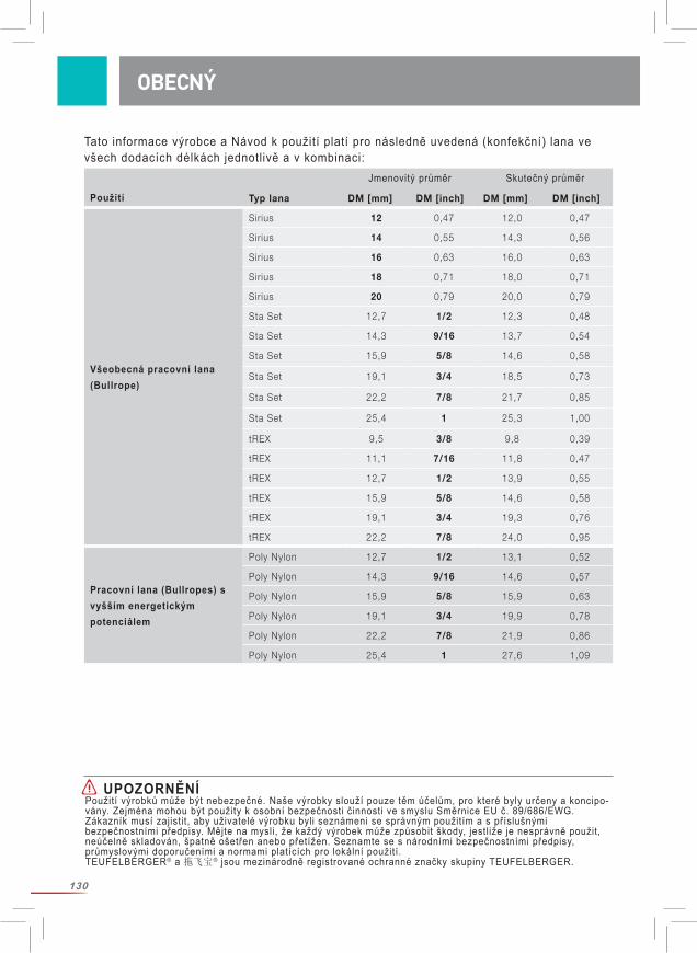
130
Tato informace výrobce a Návod k použití platí pro následně uvedená (konfekční) lana ve všech dodacích délkách jednotlivě a v kombinaci:
OBECNÝ
UPOZORNĚNÍPoužití výrobků může být nebezpečné. Naše výrobky slouží pouze těm účelům, pro které byly určeny a koncipo-vány. Zejména mohou být použity k osobní bezpečnosti činnosti ve smyslu Směrnice EU č. 89/686/EWG. Zákazník musí zajistit, aby uživatelé výrobku byli seznámeni se správným použitím a s příslušnými bezpečnostními předpisy. Mějte na mysli, že každý výrobek může způsobit škody, jestliže je nesprávně použit, neúčelně skladován, špatně ošetřen anebo přetížen. Seznamte se s národními bezpečnostními předpisy, průmyslovými doporučeními a normami platících pro lokální použití. TEUFELBERGER® a 拖飞宝® jsou mezinárodně registrované ochranné značky skupiny TEUFELBERGER.
Jmenovitý průměr Skutečný průměr
Použití Typ lana DM [mm] DM [inch] DM [mm] DM [inch]
Všeobecná pracovní lana (Bullrope)
Sirius 12 0,47 12,0 0,47
Sirius 14 0,55 14,3 0,56
Sirius 16 0,63 16,0 0,63
Sirius 18 0,71 18,0 0,71
Sirius 20 0,79 20,0 0,79
Sta Set 12,7 1/2 12,3 0,48
Sta Set 14,3 9/16 13,7 0,54
Sta Set 15,9 5/8 14,6 0,58
Sta Set 19,1 3/4 18,5 0,73
Sta Set 22,2 7/8 21,7 0,85
Sta Set 25,4 1 25,3 1,00
tREX 9,5 3/8 9,8 0,39
tREX 11,1 7/16 11,8 0,47
tREX 12,7 1/2 13,9 0,55
tREX 15,9 5/8 14,6 0,58
tREX 19,1 3/4 19,3 0,76
tREX 22,2 7/8 24,0 0,95
Pracovní lana (Bullropes) s vyšším energetickým potenciálem
Poly Nylon 12,7 1/2 13,1 0,52
Poly Nylon 14,3 9/16 14,6 0,57
Poly Nylon 15,9 5/8 15,9 0,63
Poly Nylon 19,1 3/4 19,9 0,78
Poly Nylon 22,2 7/8 21,9 0,86
Poly Nylon 25,4 1 27,6 1,09
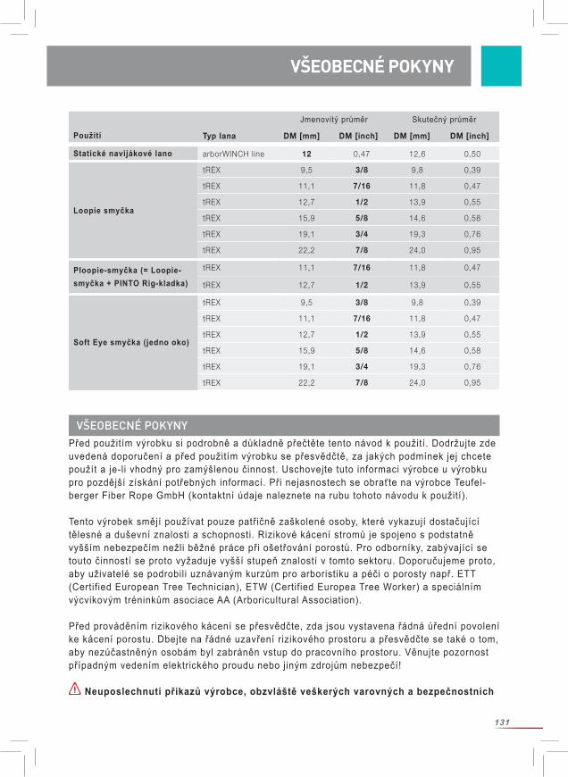
131
Před použitím výrobku si podrobně a důkladně přečtěte tento návod k použití. Dodržujte zde uvedená doporučení a před použitím výrobku se přesvědčtě, za jakých podmínek jej chcete použít a je-li vhodný pro zamýšlenou činnost. Uschovejte tuto informaci výrobce u výrobku pro pozdější získání potřebných informací. Při nejasnostech se obraťte na výrobce Teufel-berger Fiber Rope GmbH (kontaktní údaje naleznete na rubu tohoto návodu k použití).
Tento výrobek smějí používat pouze patřičně zaškolené osoby, které vykazují dostačující tělesné a duševní znalosti a schopnosti. Rizikové kácení stromů je spojeno s podstatně vyšším nebezpečím nežli běžné práce při ošetřování porostů. Pro odborníky, zabývající se touto činností se proto vyžaduje vyšší stupeň znalostí v tomto sektoru. Doporučujeme proto, aby uživatelé se podrobili uznávaným kurzům pro arboristiku a péči o porosty např. ETT (Certified European Tree Technician), ETW (Certified Europea Tree Worker) a speciálním výcvikovým tréninkům asociace AA (Arboricultural Association).
Před prováděním rizikového kácení se přesvědčte, zda jsou vystavena řádná úřední povolení ke kácení porostu. Dbejte na řádné uzavření rizikového prostoru a přesvědčte se také o tom, aby nezúčastněnýn osobám byl zabráněn vstup do pracovního prostoru. Věnujte pozornost případným vedením elektrického proudu nebo jiným zdrojům nebezpečí!
Neuposlechnutí příkazů výrobce, obzvláště veškerých varovných a bezpečnostních
VŠEOBECNÉ POKYNY
VŠEOBECNÉ POKYNY
Statické navijákové lano arborWINCH line 12 0,47 12,6 0,50
Loopie smyčka
tREX 9,5 3/8 9,8 0,39
tREX 11,1 7/16 11,8 0,47
tREX 12,7 1/2 13,9 0,55
tREX 15,9 5/8 14,6 0,58
tREX 19,1 3/4 19,3 0,76
tREX 22,2 7/8 24,0 0,95
Ploopie-smyčka (= Loopie-smyčka + PINTO Rig-kladka)
tREX 11,1 7/16 11,8 0,47
tREX 12,7 1/2 13,9 0,55
Soft Eye smyčka (jedno oko)
tREX 9,5 3/8 9,8 0,39
tREX 11,1 7/16 11,8 0,47
tREX 12,7 1/2 13,9 0,55
tREX 15,9 5/8 14,6 0,58
tREX 19,1 3/4 19,3 0,76
tREX 22,2 7/8 24,0 0,95
Jmenovitý průměr Skutečný průměr
Použití Typ lana DM [mm] DM [inch] DM [mm] DM [inch]
132
pokynů, může způsobit úrazy, věcná poškození, těžká zranění nebo dokonce smrt zúčastněných osob! Při rizikovém kácení porostů (Rigging) je nebezpečí zranění a věcného poškození obzvláště vysoké. Každé použití, které je odlišné od těchto příkazů a každé neuposlechnutí uvedených pokynů musí být pokládáno za použití mimo defino-vané oblasti použití a není tudíž pro takové způsoby použití vhodné.
Pro zamýšlenou pracovní činnost zvolte vhodné nebo legislativně předepsané osobní ochranné pomůcky.
Věnujte pozornost důležitým (národním) bezpečnostním předpisům ohledně riziko-vého kácení porostů a volbě vhodných osobních ochranných pomůcek!
Tento návod k použití jsme koncipovali jako „work in progress“. Na našem výrobním stanovišti jsme provedli dynamickou simulaci možných zátěží našich výrobků a v této práci budeme měřením dynamických údajů i nadále pokračovat. Veškeré dostupné výsledky zveřejníme na našich domovských stránkách pod www.teufelberger.com.
Pod pojmem „Rigging – rizikové kácení“ se rozumí postupné odřezávání stromu za pomoci předem spočítaného zdvíhacího systému textilních lan, kladek a (v běžném případě) kmene stromu, jako přirozené pomůcky, který je tak koncipován, že odolá vzniklým silám, které při zachycení padajících částí stromů o veliké hmotnosti vznikají.
(Konfekční) lano, které je přiloženo k této informaci výrobce, je určeno výlučně pro použití jako součást systému pro rizikové kácení porostů. Kompatibilitu této součásti s každou další propojenou součástí celého systému musí zajistit uživatel. V zodpovědnosti uživatele je zaji-stit kompatibilnost každé komponenty výrobku se spřaženými návaznými komponentami.
Upozornění: „Jednotlivé součásti celého systému jsou navzájem vystaveny střídavým silám, jejichž působení není ještě dokonale prozkoumáno a propočteno. Při rizikovém kácení jsou stromolezci, jejich výstroj a výzbroj a strom samotný vystaveni silám a zátěžím, které jsou pouze těžce kalkulovatelné.“1, Je proto úlohou uživatele, možná rizika správně odhadnout a minimalizovat.
TEUFELBERGER neodpovídá za přímé, nepřímé nebo náhodné následky/škody, které v průběhu nebo po použití výrobku vzniknou a které byly způsobeny nesprávným použitím včetně změny lana (zhotovení oka atd.), nesprávné kombinace s jinými součástmi výzbroje nebo jejich nesprávného seřazení.
Výrobky pro riggingové účely nesmí být použity jako osobní ochranné pomůcky.
Důležité je, riggingové vybavení vhodným způsobem označit tak, aby nebylo zaměněno s osobními ochrannými pomůckami, nebo jako takové použito
1 Andreas Detter, „Rigging-Techniken beim Abtragen von Bäumen. Teil 1: Kinematische Analysen“, AFZ-Der Wald 24/2008, S.1322ff.
SPRÁVNÉ POUŽITÍ
SPRÁVNÉ POUŽITÍ
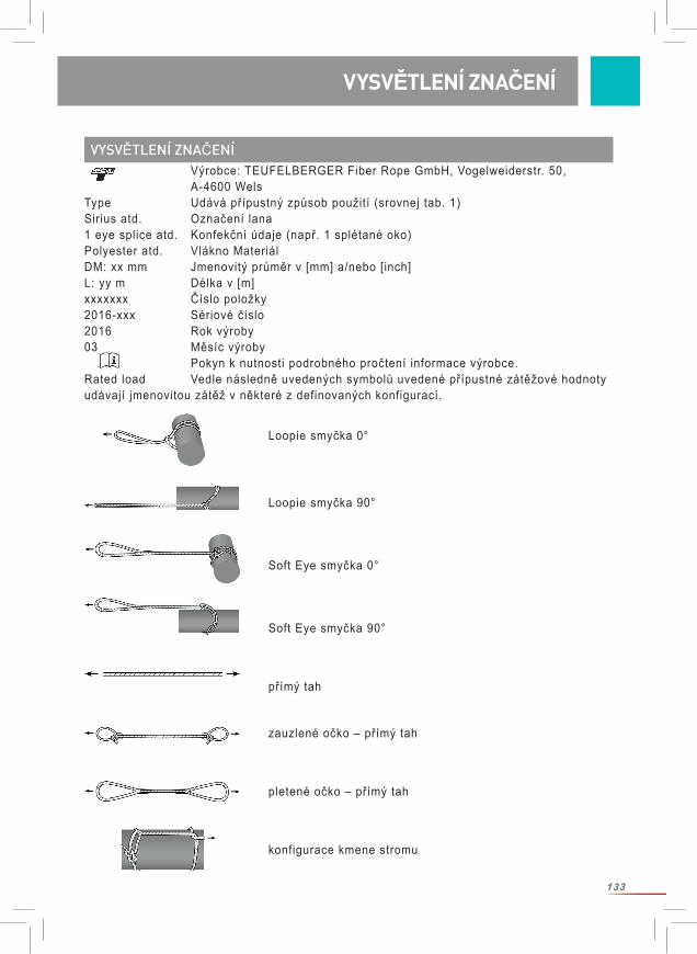
133
VYSVĚTLENÍ ZNAČENÍ Výrobce: TEUFELBERGER Fiber Rope GmbH, Vogelweiderstr. 50, A-4600 WelsType Udává přípustný způsob použití (srovnej tab. 1)Sirius atd. Označení lana1 eye splice atd. Konfekční údaje (např. 1 splétané oko)Polyester atd. Vlákno MateriálDM: xx mm Jmenovitý průměr v [mm] a/nebo [inch]L: yy m Délka v [m]xxxxxxx Číslo položky2016-xxx Sériové číslo2016 Rok výroby03 Měsíc výroby Pokyn k nutnosti podrobného pročtení informace výrobce. Rated load Vedle následně uvedených symbolů uvedené přípustné zátěžové hodnoty udávají jmenovitou zátěž v některé z definovaných konfigurací.
SPRÁVNÉ POUŽITÍ VYSVĚTLENÍ ZNAČENÍ
Loopie smyčka 0°
Loopie smyčka 90°
Soft Eye smyčka 0°
Soft Eye smyčka 90°
přímý tah
zauzlené očko – přímý tah
pletené očko – přímý tah
konfigurace kmene stromu

134
TECHNICKÉ ÚDAJE – ZÁSADNÍ DŮLEŽITÉ POZNÁMKY
2 MBL = Minimální odolnost proti lomu3 Andreas Detter, Chris Cowell et al., „Evaluation of current rigging and dismantling practices used in arboriculture“, Health and Safety Executive Research Report 668, 2008), str. 234 a násl. (http://www.hse.gov.uk/ research/rrpdf/rr668.pdf4 Namísto hmotnosti části stromu by se fyzikálně korektně muselo použít váhy části stromu. Tato se zjistí jako hmotnost [kg]*9,81m/s² a představuje sílu v [N]. Zjednodušeně se hmota 1 kg dá přibližně určit hodnotou 10 N = 1 daN = 0,01 kN.
Veškeré následující údaje se vztahují na nová, suchá lana za zkušebních podmínek. Věškeré údaje ohledně meze pevnosti platí za zachování statických podmínek.
Použitím lan se mění jejich vlastnosti: Jejich schopnosti prodloužení a jejich zatížení na mezi pevnosti klesají.Při použití v rizikovém kácení porostů je třeba vzít na zřetel povětrnostní vlivy: Vlhkost zásadně snižuje odolnost vůči mezi pevnosti a zvyšuje protažení zatíženého lana. Obzvláště mokrá lana se mohou zkracovat. Také vysoké nebo nízké teploty (v letním, příp. zimním období) ovlivňují pevnost lana. Totéž platí ohledně znečištění lana, ohledně vlivu slunečního záření ap. Při výskytu těchto vlivů zásadně počítejte se snížením meze pevnosti lana! Mějte na zřeteli, že lana vlivem nízkých teplot a obalením ledem ztvrdnou, což ovlivňuje jejich vlastnosti!Výpotky stromů (např. smoly a lepivé pryskyřice ap.) mohou vyvolat podmínky jako lepidla nebo maziva, což podstatně ovlivňuje jejich funkčnost lan na kladkách, v zauzleních atd.
Naše lana pravidelně zkoušíme ohledně MBL2 ve volných délkách (nová, suchá, za labora-torních podmínek.)
Níže uvedené přídavné údaje byly zjištěny, jak v je dalších kapitolách o technických datech popsáno. Tyto nejsou součástí našich pravidelných jakostních zkoušek. Hodnoty „MBL plete-né“ platí pouze pro firmou TEUFELBERGER zhotovené pletené očko. Pouze jeden konec lana byl opatřen pleteným spojem. Dle druhu provedení pleteného spoje může ztráta hod-noty MBL, ve srovnání s hodnotou pro „volnou délku“, podstatně kolísat. Tyto údaje slouží pouze jako přibližný ukazatel, protože nespočívají na staticky relevantních náhodných veličinách.
Upozornění: Síly, které v průběhu rizikového kácení porostů vznikají, nelze snadno určit a mohou se dramaticky odlišovat v závislosti na hmotnosti části torza stromu, Rigging-Set-Up, druhu stromu, stavu stromu a struktuře zakotvení. Špičkové hodnoty zatížení mohou vz-niknout náhle, např. když zablokuje brzdový mechanizmus. Tyto extrémní zátěže mohou vést k selhání celého lanového a kladkového systému a/nebo k ulomení nosných částí stromu.
Následně uvedené úvahy (pouze hrubá směrnice; pro správnost a úplnost těchto informací nepřebíráme záruku) spočívají pouze na údajích odborné literatury3: Ve zkouškách zjištěná zátěž na smyčce zakotvení byla v závislosti na uspořádání a skutečném scénáři zhruba 9 až 20 krát vyšší nežli hmotnost části stromu4. Podrobnosti jsou uvedeny v Rigging Research Report. Zátěž na pracovním laně je často pouze poloviční nežli zátěž na smyčce zakotvení. (Pozor: V silné závislosti na zvolené konfiguraci!)
TECHNICKÉ ÚDAJE
135
TECHNICKÉ ÚDAJE
Z toho rezultuje: Aby bylo zajištěno, že komponenty lana nepodlehnou destrukci, jestliže jsou vystaveny nárazovému zatížení, musí být odolnost proti lomu kotvící smyčky ve zvolené konfiguraci větší než 9-ti až 20-ti násobek hmotnosti kmene stromu a odolnost proti lomu riggingového lana ve zvolené konfiguraci větší než polovina odolnosti proti lomu kotvící smyčky. Nadto zvolte dostatečný bezpečnostní faktor!
Dynamické zkoušky, provedené za praktických, i když pouze simulovaných podmínek v rámci firmou Teufelberger a skupinou „treemagineers“ podporované diplomové práce, ukázaly jiné ukazatele (Hrubá směrnice! Pouze definovaná věta podmínek!): Staticky a dynamicky konfigurované hodnoty odolnosti proti lomu jsou si blízké, takže statické údaje o pevnosti jsou dobrým vodítkem pro definici akceptovatelné jmenovité nosno-sti (Working Load Limit).
Věnujte pozornost všeobecným poznámkám k technickým údajům, zde především ohledně statické závažnosti!
Údaje ohledně hodnoty „minimální odolnost proti lomu zauzlené“ platí pro následující seřazení: Oboustranně bylo provedeno očko pomocí dvojitého zauzlení Palstek (viz vyobrazení 1, strana 9)
Minimální odolnost proti lomu „na kmeni“ byla stanovena, jak je znázorněno na vyobrazeních 2-3, strana 9.
Informace ke způsobu provedení lana:
TECHNICKÉ ÚDAJE – PRACOVNÍ LANA/BULLROPES
Sirius Sta Set tREX Poly Nylon
JádroPolyester pletený
Polyester pletený Polyesterová dutá
spleť s vosko-vaným potahem
Polyamid PA6 pletený
FundaPolyester pletený
Polyester pletený, s polyuretanovým
potahem
Polyester pletený
TECHNICKÉ ÚDAJE
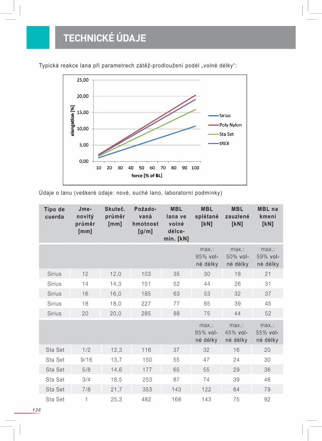
136
TECHNICKÉ ÚDAJE
Typická reakce lana při parametrech zátěž-prodloužení podél „volné délky“:
Údaje o lanu (veškeré údaje: nové, suché lano, laboratorní podmínky)
max.: 85% vol-né délky
max.: 50% vol-né délky
max.: 59% vol-né délky
Sirius 12 12,0 103 35 30 18 21
Sirius 14 14,3 151 52 44 26 31
Sirius 16 16,0 185 63 53 32 37
Sirius 18 18,0 227 77 65 39 45
Sirius 20 20,0 285 88 75 44 52
Tipo de cuerda
Jme-novitý průměr [mm]
Skuteč. průměr[mm]
Požado-vaná
hmotnost [g/m]
MBL lana ve volné délce-
min. [kN]
MBL splétané
[kN]
MBL zauzlené
[kN]
MBL na kmeni [kN]
max.: 85% vol-né délky
max.: 45% vol-né délky
max.: 55% vol-né délky
Sta Set 1/2 12,3 116 37 32 16 20
Sta Set 9/16 13,7 150 55 47 24 30
Sta Set 5/8 14,6 177 65 55 29 36
Sta Set 3/4 18,5 253 87 74 39 48
Sta Set 7/8 21,7 353 143 122 64 79
Sta Set 1 25,3 482 168 143 75 92
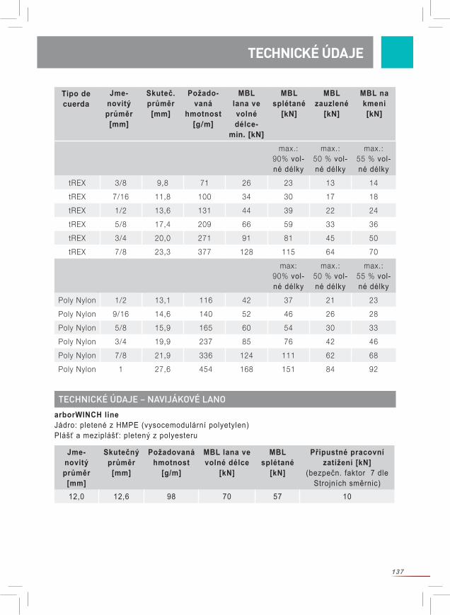
137
TECHNICKÉ ÚDAJE TECHNICKÉ ÚDAJE
max.: 90% vol-né délky
max.: 50 % vol-né délky
max.: 55 % vol-né délky
tREX 3/8 9,8 71 26 23 13 14
tREX 7/16 11,8 100 34 30 17 18
tREX 1/2 13,6 131 44 39 22 24
tREX 5/8 17,4 209 66 59 33 36
tREX 3/4 20,0 271 91 81 45 50
tREX 7/8 23,3 377 128 115 64 70
max: 90% vol-né délky
max.: 50 % vol-né délky
max.: 55 % vol-né délky
Poly Nylon 1/2 13,1 116 42 37 21 23
Poly Nylon 9/16 14,6 140 52 46 26 28
Poly Nylon 5/8 15,9 165 60 54 30 33
Poly Nylon 3/4 19,9 237 85 76 42 46
Poly Nylon 7/8 21,9 336 124 111 62 68
Poly Nylon 1 27,6 454 168 151 84 92
Tipo de cuerda
Jme-novitý průměr [mm]
Skuteč. průměr[mm]
Požado-vaná
hmotnost [g/m]
MBL lana ve volné délce-
min. [kN]
MBL splétané
[kN]
MBL zauzlené
[kN]
MBL na kmeni [kN]
Jme-novitý průměr
[mm]
Skutečný průměr
[mm]
Požadovaná hmotnost
[g/m]
MBL lana ve volné délce
[kN]
MBL splétané
[kN]
Přípustné pracovní zatížení [kN]
(bezpečn. faktor 7 dle Strojních směrnic)
12,0 12,6 98 70 57 10
arborWINCH lineJádro: pletené z HMPE (vysocemodulární polyetylen)Plášť a meziplášť: pletený z polyesteru
TECHNICKÉ ÚDAJE – NAVIJÁKOVÉ LANO
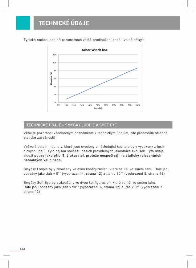
138
TECHNICKÉ ÚDAJE
Typická reakce lana při parametrech zátěž-prodloužení podél „volné délky“:
0%
2%
4%
6%
8%
10%
12%
0% 10% 20% 30% 40% 50% 60% 70% 80% 90% 100%
Elon
gatio
n [%
]
Force [%]
Arbor Winch line
Věnujte pozornost všeobecným poznámkám k technickým údajům, zde především ohledně statické závažnosti!
Veškeré ostatní hodnoty, které jsou uvedeny v následující kapitole byly vyvozeny z tech-nických údajů. Tyto nejsou součástí našich pravidelných jakostních zkoušek. Tyto údaje slouží pouze jako přibližný ukazatel, protože nespočívají na staticky relevantních náhodných veličinách.
Smyčky Loopie byly zkoušeny ve dvou konfiguracích, které se liší ve směru tahu. Dále jsou popsány jako „tah v 0°“ (vyobrazení 4, strana 12) a „tah v 90°“ (vyobrazení 5, strana 12)
Smyčky Soft Eye byly zkoušeny ve dvou konfiguracích, které se liší ve směru tahu. Dále jsou popsány jako „tah v 90°“ (vyobrazení 6, strana 12) a „tah v 0°“ (vyobrazení 7, strana 12)
TECHNICKÉ ÚDAJE – SMYČKY LOOPIE A SOFT EYE
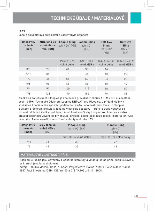
139
TECHNICKÉ ÚDAJE TECHNICKÉ ÚDAJE / MATERIÁLOVÉ
Jmenovitý průměr [inch]
MBL lana ve volné délce
min. [kN]
Loopie Slingtah v 90° [kN]
Loopie Slingtah v 0°
[kN]
Soft Eye Sling
tah v 90°[kN]
Soft Eye Sling
tah v 0°[kN]
max. 110 % volné délky
max. 130 % volné délky
max.: 55% of volné délky
max.: 65% of volné délky
3/8 26 28 33 14 16
7/16 34 37 44 18 22
1/2 44 48 57 24 28
5/8 66 72 85 36 42
3/4 91 100 118 50 59
7/8 128 140 166 70 83
Jmenovitý průměr[inch]
MBL lana ve volné délce
[kN]
Ploopie Slingtah v 90° [kN]
Ploopie Slingtah v 0°
[kN]
max. 90 % volné délky max. 110 % volné délky
7/16 34 30 37
1/2 44 39 48
tREXLano z polyesterové duté spleti s voskovaným potahem
Kladka na součástkách Ploopies je zhotovena převážně z hliníku ASTM 7075 a šlechtěné oceli 174PH. Technické údaje pro Loopies NEPLATÍ pro Ploopies, a přidání kladky k součástce Loopie může způsobit podstatnou změnu odolnosti proti lomu. U Ploopies s větším průměrem limituje kladka pevnost celé soustavy – proto je třeba věnovat po-zornost odolnosti kladky proti lomu. A odolnost součástky Loopie proti lomu se s velkou pravděpodobností vlivem kladky snižuje, protože kladka poškozuje textilní materiál při vyso-kém tahu. Zaznamenali jsme snížení hodnoty o zhruba 15%.
MATERIÁLOVÉ VLASTNOSTI PŘÍZÍ
Následující údaje jsou odvozeny z odborné literatury a vztahují se na příze, tudíž surovinu, ze kterých jsou lana zhotovena. Zdroje: Tabulka vláknin dle P.-A. Koch: Polyesterová vlákna, 1993 a Polyamidová vlákna 1997 Fact Sheets od DSM: CIS YA100 a CIS YA102 z 01-01-2008;
140
MATERIÁLOVÉ
Materiál Polyester (Polyetylen-terephthalat)
Polyamid(Polyamid 6)
HMPE(vysocemodu-
lární polyetylen)
Elektrické vlastnosti:Elektrický specifický odpor
Ωcm 1011-1014 109-1012
Elektrický odpor Ω >1014
Absorpce vlhka za normálního klimatu
% 0,2-0,5 3,5-4,5 0
Chemická odolnost
Odolnost proti kyselinám
Dobrá opro-ti zředěným minerálním
kyselinám a orga-nickým kyselinám
za pokojových teplot
Citlivější oproti zředěným
kyselinám nežli polyester
vynikající
Odolnost proti zásadám Dostačující. Koncentrova-
né, příp. horké zředěné roztoky napadají vlákna.
Velmi dobrá odolnost oproti
zásadám při pokojových teplotách.
Při vysokých koncentracích nebo teplotách
nastává narušení vláken.
vynikající
Pozor při silně oxidujících lát-
kách.
Výslovně varujeme před stykem s chemickými látkami!
Termická odolnost: Vodivost tepla W/mK 0,25 0,24 20 axial
0,2 transveral
Bod tání °C 250-260 215-220 144-152
Odolnost proti stálé teplotě
°C 120 90 70
Vlastnosti za studena Mírný nárůst pev-nosti, silné ztráty
roztažnosti.
Velmi dobrá odolnost proti
chladu. Mírný nárůst
pevnosti, silné ztráty roztažnosti.
Při -60°C 110% pevnosti a 90%
roztažnosti ve srovnání s
+23°C.
141
Materiál Polyester (Polyetylen-terephthalat)
Polyamid(Polyamid 6)
HMPE(vysocemodu-
lární polyetylen)
Odolnost proti počasí Po 1 roce vy-stavení vlivům
počasí ještě 40-47% dvojitých ohybů do lomu.
Mírná stabilita proti vlivům světelného
záření.
V prakt.testu (9 měsíců venku) podobná zbyt-ková odolnost
jako u polyeste-ru (46%): 47%
Chování při hoření Nehoří trvale, má sklony k od-
kapávání
Jako polyester. Výrazně hoří při zbarvení nebo
impregnaci
Nehoří trvale.
Odstranění Domácí odpad Domácí odpad Domácí odpad
MATERIÁLOVÉ
MATERIÁLOVÉ VLASTNOSTI KOVOVÝCH SOUČÁSTEK
Informace o kovových součástkách vycházejí m. j. z patřičných Pokynů pro uživatele, které jsou výrobku přibaleny.Některé hodnoty v níže uvedené tabulce jsme přebrali z listin údajů o materiálu a nebyly na vlastním výrobky přezkoušeny. Určité faktory mohou tyto hodnoty ovlivnit (např. eloxační vrstva způsobuje výrazné snížení elektrické vodivosti).
Materíal šlechtěná ocel 174PH hliník ASTM 7075Elektrické vlastnosti:
Specifický elektrickýodpor Ωcm 8*106
5,15*106
(Eloxační vrstva snižuje vodivost)
Elektrický odpor Ω
Absorpce vlhkosti % 0 0
Chemická odolnost
Odolnost proti kyselinámSilné kyseliny a zásady mohou mít silné koro-
zívní účinky. V případě znečištění, je třeba kladku
dle návodu k použití kladky odpovídajícím způsobem vyčistit a
přezkoušet
Silné kyseliny a zásady mohou mít silné koro-
zívní účinky. V případě znečištění, je třeba kladku
dle návodu k použití kladky odpovídajícím způsobem vyčistit a
přezkoušet
Odolnost proti zásadám
Vyvarujte se styku s chemikáliemi!
142
POUŽITÍ A OMEZENÍ
Nežli použijete lana na rizikové kácení porostů, přesvědčte se, zda je tato metoda nejvhodnější. Přesvědčte se, zda je bezpečné slézání tohoto stromu a jestli je bezpečné tento strom rizikovým způsobem porazit. Jestliže odpovědi na tyto dvě otázky znějí „ano“, potom je tato metoda vhodná. Zvažte také, jestli není bezpečnější použít strojní techniku (jeřáb, pracovní plošiny nebo pod.) nežli rizikové kácení.
Materíal šlechtěná ocel 174PH hliník ASTM 7075
Postup při znečištění
Určité druhy znečištění mohou mít korozívní
účinky. Znečištění může snížit správnou funkčnost mechanických součástek. Proto kladku pravidelně ošetřujte, udržujte a po-
drobte důkladné kontrole.
Určité druhy znečištění mohou mít korozívní
účinky. Znečištění může snížit správnou funkčnost mechanických součástek. Proto kladku pravidelně ošetřujte, udržujte a po-
drobte důkladné kontrole.
Tepelné vlastnosti:Tepelná vodivost W/mk 178,4 130
Provozní teploty kladky Vhodná pro běžné okolní teploty (-40 až +50 °C)
Vhodná pro běžné okolní teploty (-40 až +50 °C)
Výskyt ledu Žádné následky při > -40°C
Žádné následky při > -40°C
Odolnost proti povětrnostním vlivům
Určité povětrnostní vlivy mohou vyvolat korozív-ní účinky. Proto kladku
dle návodu k použití pravidelně ošetřujte, udržujte a podrobte důkladné kontrole.
Určité povětrnostní vlivy mohou vyvolat korozív-ní účinky. Proto kladku
dle návodu k použití pravidelně ošetřujte, udržujte a podrobte důkladné kontrole. .
Odolnost proti ultrafialovému záření
Žádné následky při běžných klimatických
podmínkách
Eloxační vrstva může poblednout
Hořlavost nehoří nehoří
Odstranění běžná recyklace běžná recyklace
POUŽITÍ A OMEZENÍ
143
1)O
K ke
slé
zání
?
OK
k riz
ikov
ému
káce
ní?
OK
pro
stro
jní t
ěžbu
?x
2)O
K ke
slé
zání
?
OK
k riz
ikov
ému
káce
ní?
OK
pro
stro
jní t
ěžbu
?
3)O
K ke
slé
zání
?x
OK
k riz
ikov
ému
káce
ní?
x
OK
pro
stro
jní t
ěžbu
?
4)O
K ke
slé
zání
?x
OK
k riz
ikov
ému
káce
ní?
x
OK
pro
stro
jní t
ěžbu
?x
Volb
a st
rom
olez
ecký
ch a
/neb
o ře
zací
ch b
odů
dle
form
y st
rom
u a
jeho
str
uktu
ráln
ích
před
nost
í, bu
ďto
na s
trom
ě ne
bo s
ouse
dním
str
omě
nebo
v o
bou.
Zváž
it hm
otno
st ř
ezan
ých
část
í, šp
ičko
vé h
odno
ty a
po
zice
oso
b(y)
na
stro
mě.
Kde
příp
ustn
é, k
usy
shaz
ovat
Pro
č. 3
neb
o 4:
Můž
e bý
t str
om s
tabi
lizov
án p
ro s
lézá
ní n
ebo
rizik
ové
káce
ní?
Nap
ř. p
omoc
í pro
vázá
ní, u
pevn
ění n
ebo
pode
-př
ením
.
Sezn
ámit
celý
tým
s p
láne
m
Je m
ožný
přís
tup
pro
jeřá
b ne
bo p
raco
vní p
loši
nu?
Jsou
dal
ší m
ožno
sti,
příp
. vy
tvoř
ení v
stup
u
Použ
ití je
řábu
/plo
šiny
pr
o př
ístu
p ne
bo k
ácet
po
moc
í jeř
ábu
Stro
m p
okác
et
Riz
ikov
é ká
cení
nen
í nut
né
Volb
a vh
odné
ho n
áčin
íST
OP!
Situ
aci z
novu
zvá
žit
nebo
zvá
žit m
ožno
sti
dle
č. 3
neb
o 4
Plán
při
jat
Plán
nep
řija
t
RB
AN
O
AN
O
AN
O
NE
NE
MO
ŽNO
ST S
TRO
-
JNÍ T
ĚŽBY
MO
ŽNO
ST R
IZIK
O-
VÉH
O K
ÁCEN
Í
=
Zhod
noce
ní s
tupn
ě riz
ika
Ods
tran
it šk
ody
Volb
a př
ijate
lné
tech
no-
logi
e
RB
RB
RB
RB
8 (A
ndre
as D
ette
r, C
hris
Cow
ell e
t al
., „
Eva
luat
ion
of c
urre
nt r
iggi
ng a
nd d
ism
antli
ng p
ract
ices
use
d in
ar
boric
ultu
re“,
Hea
lth a
nd S
afet
y E
xecu
tive
Res
earc
h R
epor
t 66
8, 2
008)
POUŽITÍ A OMEZENÍ

144
UPOZORNĚNÍ PŘED POUŽITÍM
Než začnete s rizikovým kácením kácením stromů: Proveďte přesnou analýzu možných rizik. Každý uživatel je zodpovědný za podstatné a „aktuální“ vyhodnocení možných rizik, která zamýšlené práce vykazují, a to včetně výskytu možných nouzových případů. V každém případě musí být provedena důkladná vizuální kontrola stromu. Naplánujte a zorganizujte veškeré pracovní dílčí úkony. Mějte na zřeteli, že jednotlivé části téhož stromu se mohou různě při kácení zachovat. Proto můžou být pro různé úseky také rozdílné aplikace, techniky a opatření nutná. Rizikové kácení porostů je v zásadě týmová práce. Dbejte na to, aby každý člen pracovní čety přesně znal svoje pracovní zadání. Stanovte jasná pravidla pro komunikaci všech zúčastněných osob např. dohodou o jednoznačných akustických signálů nebo znamení rukami, popř. použijte vysílaček ap. Zdržování se pod zavěšenými břemeny ja přísně zakázané (nebezpečí života)! Přitom je třeba mít na zřeteli, že vítr může odchýlit směr pádu části stromu, že zavěšená část stromu se otočí nebo vyvrátí z axiálního směru. Prostor pod pracovním úsekem je třeba v dostatečné vzdálenosti uzavřít a zabránit vstupu nezúčastněných osob, které by třeba neúmyslně mohly vstoupit do nebezpečných míst. Minimujte možná rizika a proveďte opatření, která zabrání vzniku možných úrazů. Před začátkem pracovních činností musí být vypracován plán záchranných opatření, který obsahuje všechna možná nebezpečí. Před a během použití pracovních pomůcek zvažte, jaká záchranná opatření lze v případě potřeby bezpečně a účinně provést. Přitom je třeba zvážit situaci každé zúčastněné osoby. Ustanovte bezpečnostní faktory. Zvolte tu nejbezpečnější techniku kácení pro Váš způsob použití! Zvolte vhodné vybavení pro rizikové kácení porostů ve správné konfiguraci. Učiňte veškerá opatření k zajištění bezpečnosti stromolezce! Použijte předepsané osobní vybavení pro zamezení pádu (osobní ochranné pomůcky)! Stromolezec a jeho záchranný systém – PSA, se musí nacházet mimo možné dráhy pádu odstraněné části stromu a stromolezeckého vybavení. Mějte prosím na zřeteli, že při přetržení lana může dojít k silnému vymrštění lana a s tím spojeným pohybem používaného náčiní v koruně stromu. Obzvláště nebezpečné situace mohou vzniknout při nárazu části stromu do kmene, který se může tímto vlivem rozhoupat. Pracovní četa musí znát následky vzniklých sil na struk- turu ukotvení a na polohu stromolezce/ců, aby tak mohla možné riziko snížit ma přijatelnou míru. Stromolezec musí mít možnost, před začátkem pracovních činností strom opustit. Stromolezec by měl mít ve vybavení příruční pilu. Mějte na zřeteli zodpovědnost za plánovanou pracovní činnost. Jmenujte odbornou osobu, která převezme zodpovědnost za plánovaný postup všech prací rizikového kácení porostů.
Upozornění: Zátěže a vzniklé síly, které u rizikového kácení stromů mohou vzniknout se dají jen těžko předem stanovit mohou se dramaticky měnit dle hmotnosti části stromu, dle
UPOZORNĚNÍ PŘED POUŽITÍM
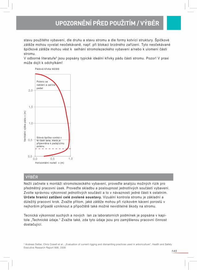
145
UPOZORNĚNÍ PŘED POUŽITÍM
stavu použitého vybavení, dle druhu a stavu stromu a dle formy kotvící struktury. Špičkové zátěže mohou vyvstat neočekávaně, např. při blokaci brzdného zařízení. Tyto neočekávané špičkové zátěže mohou vést k selhání stromolezeckého vybavení a/nebo k ulomení části stromu. V odborné literatuře5 jsou popsány typické ideální křivky pádu části stromu. Pozor! V praxi může dojít k odchylkám!
VÝBĚRNežli začnete s montáží stromolezeckého vybavení, proveďte analýzu možných rizik pro předmětný pracovní úsek. Proveďte skladbu a posloupnost jednotlivých součástí vybavení. Zvolte správnou výkonnost jednotlivých součástí a to v návaznosti jedné části k ostatním. Určete hranici zatížení celé zvolené soustavy. Vizuální kontrola stromu je základní a důležitý pracovní krok. Zvažte přitom, jaké zátěže mohou při rizikovém kácení porostů v nejhorším případě vzniknout a připočtětě také možné neviditelné škody na stromu.
Tecnická výkonnost suchých a nových lan za laboratorních podmínek je popsána v kapi-tole „Technické údaje.“ Zvažte také, zda tyto údaje jsou pro zamýšlenou pracovní činnost dostačující.
5 Andreas Detter, Chris Cowell et al., „Evaluation of current rigging and dismantling practices used in arboriculture“, Health and Safety Executive Research Report 668, 2008
UPOZORNĚNÍ PŘED POUŽITÍM / VÝBĚR
0,00,0
0,5 1,0
0,5
1,0
1,5
2,0
Vert
ikál
ní v
ýška
pád
u v
(m)
Horizontální rozteč v (m)
Poleno se naklání a začíná padat
Silová špička vzniká v té části lana, která je připevněna k padajícímu polenu.
Pádová křivka těžiště
146
Mějte přitom na zřeteli, že dynamické zátěže způsobují podstatně vyšší síly nežli zátěže statické, že koncové spoje lana vykazují nižší odolnost proti lomu nežli volné lano. (Zauzlení lana snižují podstatně odolnost proti lomu – snížení o více nežli 50% je možné. Při správně provedených spojích lan se musí vycházet ze snížení ve velikosti mezi 10-20%.) že uspořádání lan a smyček má podstatný vliv na působící síly, a že ve smyslu bezpečnosti je třeba vždy vycházet z nejhorší možnosti („Worst-Case-Szenario“) a z možnosti vzniku nepředvídaných rušivých vlivů.
Dynamické zátěže vznikají tehdy, když padající nebo kývající předmět spadne na stromo-lezecký systém. Čím rychleji nebo náhleji musí být zátěž zachycena, o to vyšší dynamické zatížení vzniká. V takovýchto případech může dynamické zatížení dosáhnout až mno-honásobných hodnot zatížení statického. Vaše pracovní činnost musí být zvolena tak, aby dynamické zátěže byly vyloučeny a/nebo byly konrolovatelné. Věnujte pozornost nosnosti kotvících smyček, protože vyvinuté energetické zátěže zde mohou vyvíjet až dvojnásobek sil, které působí na riggingové lano.
Na pracovišti musí být přítomna kompetentní odborná osoba, která je patřičně zaškolena ohledně výpočtu/odhadu vzniklých zátěží, která je obeznámena s hmotností stromu, výškou pádu, typy a délkou lan a jinými podstatnými veličinami, a která dohlíží na rizikové kácení porostů. Z odborných studií6 vyplývá, že zátěž na kotevní smyčce je zhruba 9-20 krát vyšší nežli hmotnost části stromu. Pozor! Jedná se pouze o hrubý odhad!
Přesvědčte se, že vlastnosti lana odpovídají zamýšlenému použití!
Zvolte vždy odpovídající bezpečnostní faktor. Z věstníku „International Guidelines on the Safer Use of Fiber Rope“ (CI 1401) Institutu pro bezpečnost lan si prosím vyberte potřebná doporučení k volbě bezpečnostního faktoru. Zdarma k náhledu pod www.ropecord.com. Pro zdvíhací účely doporučuje Směrnice o strojních zařízeních č. 2006/42/EG bezpečnostní faktor v hodnotě minimálně 7 (poměr odolnosti proti lomu nového nekonfekčního lana ke statické zátěži). Odborná literatura nadto doporučuje všechny odhadnuté zátěže vynásobit faktorem 1,57.
Mějte na zřeteli, že celý systém unese pouze zátěže jako jeho nejslabší komponenta.
Odvinutí cívky (obr. 8, strana 19)Při odvíjení lana z cívky je vhodné, když se cívka volně točí. Toho docílíme nasazením tyče do středu cívky, kdy můžeme lano odvíjet za současného otáčení cívky. Nikdy neodvíjejte lano z ležící cívky, protože hrozí nebezpečí zkrutu lana.
PROVOZ A POUŽITÍ
6 Brian Kane et al., „Forces and Stresses Generated During Rigging Operations“, Arboriculture & Forestry 2009, 35(2), 68-74.7 Andreas Detter, Chris Cowell et al., „Evaluation of current rigging and dismantling practices used in arboriculture“, Health and Safety Executive Research Report 668, 2008
PROVOZ A POUŽITÍ
147
PROVOZ A POUŽITÍ
Odvíjení bubnu trosového lana: Odvíjení lana z bubnu trosového lana se děje od vnitřního konce. Lano se odvíjí proti smyslu hodinových ručiček. Při odvíjení ve smyslu hodinových ručiček vznikají zauzliny. V tomto případě navlečta lano zpět, otočtě buden a odvíjejte znovu od středu. Nyní se lano odvíjí proti smyslu hodinových ručiček a bez zauzlení.
Uzle:
Mějte na zřeteli, že každé zauzlení podstatně snižuje odolnost lana prot lomu. Při našich měřeních bylo použito dvojitého zazlení Palstek.
Návod pro dvojitý uzel Palstek (obr. 9-13, strana 20)
Spoj lana:
Mějte na zřeteli, že každý spoj lana snižuje jeho odolnost proti lomu. Lanové spoje zho-tovujte pouze tehdy, jestliže jste odborně zaškolen! Pokyny ke splétání pro výrobky Sirius, Poly Nylon, Sta Set, arborWINCH line a tRex najdete na naší domovské stránce www.teufelberger.com jako Download ke stažení.Nebřebíráme žádné záruky za lanové spoje nebo jejich dodatečné vybavení, které nebyly zhotoveny firmou TEUFELBERGER.
Loopie / Ploopie smyčka: Umístětě kladku Pulley na Loopie Sling a narovnejte důkladně spoj lana. (obr. 14-15, strana 20)
Obepněte strom a protáhnětě kladku Pulley skrz Loopie Sling. Loopie Sling může být v délce seřízen: Stáhněte těsně smyčku a přezkoušejte stabilní usazení smyčky a kladky. (obr. 16-19, strana 21)
Soft Eye Sling: Umístěte dle následujících vyobrazení očko s přípravkem Pulley okolo stromu. Ztužený konec lana slouží jako pomůcka k navlečení. (obr. 21-24, strana 21)
Zasuňte volný konec mezi smyčku a strom. (obr. 25, strana 22)
Namontujte pracovní lano pomocí dvojitého uzle Palstek, jak blíže popsáno v kapitole o tech-nických údajích. (obr. 26-29, strana 22)
Po montáži přezkoušejte umístěný systém! Dbejte, aby lano nebylo v bezprostředním styku s ostrými a obrusnými předměty nebo plochami!
Následující schéma Vám pomůže při bezpečné práci při rizikovém kácení porostů.
PROVOZ A POUŽITÍ
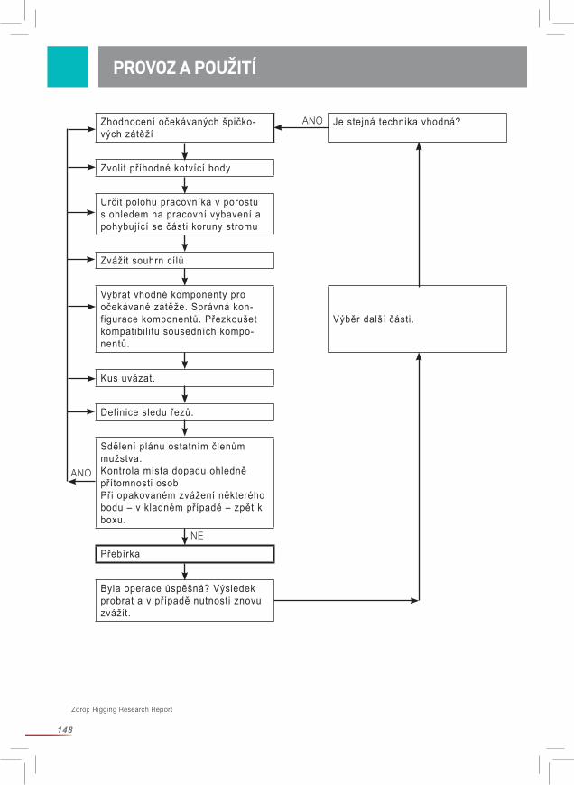
148
Zhodnocení očekávaných špičko-vých zátěží
Je stejná technika vhodná?
Zvolit příhodné kotvící body
Určit polohu pracovníka v porostu s ohledem na pracovní vybavení a pohybující se části koruny stromu
Zvážit souhrn cílů
Vybrat vhodné komponenty pro očekávané zátěže. Správná kon-figurace komponentů. Přezkoušet kompatibilitu sousedních kompo-nentů.
Výběr další části.
Kus uvázat.
Definice sledu řezů.
Sdělení plánu ostatním členům mužstva.Kontrola místa dopadu ohledně přítomnosti osobPři opakovaném zvážení některého bodu – v kladném případě – zpět k boxu.
Přebírka
Byla operace úspěšná? Výsledek probrat a v případě nutnosti znovu zvážit.
ANO
ANO
NE
PROVOZ A POUŽITÍ
Zdroj: Rigging Research Report

149
PROVOZ A POUŽITÍ
Za účelem snížení vznikajících sil, zredukujte hmotnost části stromu, zredukujte délku části stromu, umístěte blok co nejblíže u místa řezu blokovou kladku nasaďte nad místem řezu (na stejném stromě nebo na sousedních stromech/strukturách) zabraňte prověšení smyčky Bullrope.
POZOR: Toto jsou pouze zásadní doporučení. Při Vašem konkrétním použití mohou na-stat důvody použití jiných technik.
Pokud možno, zabraňte kývavým pohybům!
Zkroucení lana (relativně k podélné ose) snižuje jeho životnost! Vzorek umístěný na opláštění lan Sirius pomáhá poznat zakroucení lana.
Lana s vyšším stupněm prodloužení mohou absorbovat více energie. Všechna lana se prodlužují – delší lano více nežli kratší. Prodloužení lana je závislé na jeho zatížení. Mějte ale na zřeteli, že prodloužení lana signalizuje možné nebezpečí! Prodloužené lano může zavěšené břemeno pohybovat nežádoucím směrem anebo také nebezpečným způsobem. Prodloužené lano může se může opět smrštit a způsobit vážná zranění. Lano si nikdy neomotávejte kolem ruky nebo jiných částí Vašeho těla! Při rizikovém kácení porostů nevstupujte na pracovní lana. Udržujte náležitý odstup od větví, nářadí a jiných součástí pracovních lan, která se rychle pohybují. Mějte na zřeteli, že výška pádu zavěšeného břemene se prodloužením lana zvětšuje! Použití lan s vyšším protažením může zhoršit kontrolu nad vzdálenější oblastí stromu.
Pokyn obzvláště při použití navijákového lana: Nevstupujte do prostoru přímého tahu lana. Při vysokých zátěžích vzniká vlivem pružnosti syntetických vláken v případě přetržení lana ohromná energie, která může způsobit vážná, až smrtelná zranění. Nebezpečí vzniká pro osoby, které se zdržují v pracovním prostoru lana, které je nadměrně zatížené. V případě přetržení lana se toto náhle smrští. Smrštění lana může způsobit těžká zranění včetně usmrcení. Informujte všechny Vaše spolupra-covníky o tomto nebezpečí. Zajistěte, aby spolupracovníci a nezúčastněná veřejnost se nezdržovali v nebezpečné zóně. Při neustálém navíjení lana jedním směrem, jako např. při použití navijáku, je vhodné lano čas od času navíjet obráceným směrem.
Použití s jinými součástmi výzbroje: Zde je třeba zajistit, aby byly dodrženy doporučení pro použití jiných součástí. Přesvědčte se, zda všechny součásti vybavení jsou kompatibilní, obzvláště poměr průměrů D/d, kde D je průměr kladky k průměru lana d zvolte pokud možno veliký. Průměr drážky kladky musí odpovídat průměru lana Zajistěte, aby všechny komponenty byly ve správném sledu seřazeny.
Při nedodržení těchto pokynů se zvyšuje riziko těžkých až smrtelných zranění.
PROVOZ A POUŽITÍ
150
PRAVIDELNÁ KONTROLA
VAROVÁNÍ – BEZPEČNOSTNÍ POKYNY
Zásadně platí: Jestliže uživatel z nějakého – byť na první pohled malicherného – důvodu si není jist, že výrobek odpovídá zamýšlenému účelu, musí jej vyřadit z provozu a učinit neupotřebitelným nebo jej vyloučit a viditelným způsobem označit, aby nebyl omylem použit. Další použití je možné teprve po kontrole odbornou osobou a písemném souhlasu.
Prudká zátěž nárazem může zapříčinit výměnu lana. Vlastnosti lana zachycovat dynamické zátěže při běžném pracovním provozu a vlivem nárazů ubývají. Použité lano již nevykazuje elasticitu lana nového a nemůže proto absorbovat tolik kinetické energie, špičkové zatížení stoupá. Současně klesá odolnost lana proti lomu.
Před a po každém použití zkontrolujte výrobek dle následujících pokynů: Před a po každém použití podrobte výrobek vizuální a hmatové zkoušce, aby byla zajištěna celistvost, bezvadný provozní stav a správná funkčnost.
Podrobte celé lano vizuální zkoušce ze všech stran a po celé jeho délce. Prohmatejte i očividně nepoškozené lano ohledně skrytých poškození v jádře lana, které mohou vznikn-out častým ohybem nebo místním přetížením. Věnujte pozornost termickým poškozením (skelný povrch lana), které mohou vzniknout příliš vysokým třením v celém systému. Zvláštní pozornost věnujte oddílu lana, který je uvázán jako lodní smyčka okolo kmene stromu. Tento díl je obvykle vystaven zvýšeným zátěžím a bývá proto často poškozen. Může se stát, že je třeba tento díl lana odříznout, zhotovit nový splet, nebo použit druhý konec lana. Při pochy-bách je třeba yýrobek vyřadit!
Pracovní lana Sirius Bullropes jsou v pravidelných odstupech označeny příčnými pruhy. Jestliže se jejich odstup změní (pravidelně zvětší), je to znamení lokálního přetížení. Taková část lana nesmí být dále používána. Důsledně varujeme před použitím lan s příznaky opotřebení. Používejte zásadně bez-vadná lana, která nevykazují řezy, zauzlení nebo poškozené pramence. Vyvarujte se oděru lana třením přes hrubé povrchy. Dbejte na pravidelné opotřebení. Přetržené lano v žádném případě nenavazujte zauzlením, nýbrž jej vyřaďte!
Doporučujeme o použití (datum, doba použití, podmínky) a přezkoušení (datum, zkušební komisař, nápadné změny) vést písemné zápisy. Věnujte také pozornost národním předpisům o četnosti zkušebních intervalů.
Kontrolujte vždy celé lano včetně koncových spojů a hardware! Při sebemenších pochybnostech je třeba výrobek vyřadit, příp. nechat přezkoušet odbornou osobou.
PRAVIDELNÁ KONTROLA
151
Zkušební listina: Povinné zkoušky: Kontrola celkového stavu, stáří, úplnosti, znečištění, správné skladby. Kontrola štítku: štítek umístěn a čitelný ano/ne, čitelný rok výroby. Kontrola všech jednotlivých součástí ohledně mechanických poškození jako: řezy, trhliny, zářezy, oděrky, deformace, žebrování, zákruty, stlačení, zhutnění. Kontrola všech jednotlivých součástí ohledně termických nebo chemických poškození jako: otaveniny, zatvrdnutí, ztužení, zbarvení. Kontrola všech kovových součástí ohledně výskytu koroze a deformací. Kontrola stavu a úplnosti koncových spojů, švů (žádné oděrky šicí příze), vázacích spojů (např. výskyt přesunu konců), správné zauzlení.
Pravidelná kontrola výzbroje je bezpodmínečně nutná. Vaše osobní bezpečnost závisí na účinnosti a době expozice Vašeho vybavení!
Pro získání dalších informací Vás odkazujeme na věstník CI 2001 — Fiber Rope Inspection and Retirement Criteria – Lanového institutu. K nahlédnutí pod www.ropecord.com.
Údržbu výstroje smí provádět pouze výrobce.
Skutečná životnost je v podstatné míře závislá na celkovém stavu výrobku, který je ovlivněn četnými faktory (viz shora). Životnost se také může jediným extrémním vlivem zkrátit na jedno jediné použití anebo ještě méně, jestliže se zařízení poškodí ještě před prvním použití (např. vlivem nevhodné přepravy). Při pouze sporadickém použití (jeden týden v roce) a správném skladování (viz Přeprava, skladování a čištění) může doba použitelnosti výrobku obnášet až 5 roků od data výroby. Rok výroby je uveden na štítku výrobku. Jestliže stáří výrobku nelze jednoznačně určit, je třeba jej vyřadit z provozu.
Mechanické opotřebení nebo jiné nežádoucí vlivy jako např. působením přímého slunečního záření mohou životnost silně omezit. Vybělená místa nebo oděrky na vláknech/nebo pásech, zbarvení a zatvrdlá místa jsou neklamným signálem pro stažení zařízení z provozu. Bližší obsahuje kapitola „Pravidelné zkoušky“.
Všeobecně platnou zásadu o délce životnosti výrobku nelze vyslověně a kvalifikovaně prohlásit, protože tato podléhá nejrůznějším faktorům, jako např. vlivu ultrafialového záření, způsobu a četnosti použití, péči o výrobek, povětrnostním vlivům, jako led nebo sníh, vlivům okolí, jako sůl, písek, kyseliny z akumulátorů ap., teplotním vlivům (mimo běžných klima-tických podmínek), mechanickým deformacím a/nebo výskytu puklin.
Kontrolujte vždy celé lano včetně koncových spojů a hardware! Při sebemenších pochyb-nostech je třeba výrobek vyřadit, příp. nechat přezkoušet odbornou osobou.
ÚDRŽBA
ŽIVOTNOST
ÚDRŽBA / ŽIVOTNOST

152
Při přepravě výrobku dbejte na ochranu proti světelnému záření a znečištění ve vhodném obalu (odolný proti vlhkosti, neprůsvitný).
Skladovací podmínky: Ochrana proti ultrafialovému záření (sluneční osvit, svářecí přístroje..), V suchu a čistotě, Při pokojových teplotách (15 – 25°C), Nikoliv v blízkosti chemických látek (kyselin, zásad, kapalin, par, plynů...) a jiných agresivních podmínek, Mimo předměty s ostrými hranami.
Výrobek proto skladujte v suchu, za přístupu vzduchu v neprůsvitném obalu vzdorujícím vlhkosti. Při skladování zabraňte vzniku zkroucení lana! Dbejte na čistotu výrobku! Abrazívní znečištění poškozuje lano. Vlhká a znečištěná lana mohou být napadena plísněmi.
K čištění použijte vlažnou vodu a jemný prací prostředek. Po očistě výrobek opláchněte čistou vodou a před uskladněním vysušte. Výrobek sušte přirozeným způsobem, nikoliv v blízkosti ohně nebo jiných zdrojů tepla.
K desinfekci používejte pouze přípravků, které nemají žádný vliv na použité syntetické látky.
Při nedodržení těchto pokynů ohrožujete svoji osobu!
PŘEPRAVA, SKLADOVÁNÍ A ČIŠTĚNÍ
PŘEPRAVA, SKLADOVÁNÍ A ČIŠTĚNÍ
153
PROHLÁŠENÍ O SHODĚ VÝROBKU PRO LANO JAKO SPLÉTANÝ CELEK
Označení a) Sirius 12 / 14 / 16 / 18 / 20mmb) arborWINCH line 12mm
Funkce Nosné lano pro použití při rizikovém kácení porostů
Model Viz označení
Typ a) Splétané jádrové lano s opláštěním z materiálu PES/PESb) Splétané jádrové lano z opláštěním z materiálu HMPE/PES s mezipláštěm z PES.
Číslo série Viz štítek na laně v celkové délce
Obchodní označení Viz označení
Firma: TEUFELBERGER Fiber Rope GmbH Vogelweiderstr. 50 A-4600 Welstímto prohlašuje, že následně uvedené strojní zařízení:
je ve shodě s ustanoveními Strojní bezpečnostní směrnice 2010 BGBL. 2008_II_282 a tím také se Směrnicí o strojních zařízeních 2006/42/ES v platném znění.
Wels, dne 20. leden 2016 Wels, dne 20. leden 2016
Technická zodpovědnost Oprávněný k vydání DI. Rudolf Kirth Rainer Morawa, MBATechnický vedoucí Fiberrope Jednatel FiberropeTEUFELBERGER Fiber Rope GmbH TEUFELBERGER Fiber Rope GmbHVogelweiderstraße 50 Vogelweiderstraße 50A-4600 Wels A-4600 Wels
PROHLÁŠENÍ O SHODĚ VÝROBKU
154
Označení a) Sta Set ½ / 9/16 / 5/8 / ¾ / 7/8 1 inchb) tREX 3/8 / 7/16 / ½ / 5/8 / ¾ / 7/8 inchc) Poly Nylon ½ / 9/16 / 5/8 / ¾ / 7/8 / 1 inch
Funkce Nosné lano pro použití při rizikovém kácení porostů
Model Viz označení
Typ a) Splétané jádrové lano s opláštěním z materiálu PES / PES s polyuretanovým obalem b) Dutá spletenina z materiálu PES s s voskovaným potahemc) Splétané jádrové lano s opláštěním z materiálu PA6 / PES
Číslo série Viz štítek na laně v celkové délce
Obchodní označení Viz označení
Firma: TEUFELBERGER Fiber Rope Corp. 848 Airport Road Fall River, MA 02720-4735, USAtímto prohlašuje, že následně uvedené strojní zařízení:
je ve shodě s ustanoveními Strojní bezpečnostní směrnice 2010 BGBL. 2008_II_282 a tím také se Směrnicí o strojních zařízeních 2006/42/ES v platném znění.
Fall River, dne 20. leden 2016 Fall River, dne 20. leden 2016
Technická zodpovědnost Oprávněný k vydání John Tedder Chris LavinTechnický vedoucí JednatelTEUFELBERGER Fiber Rope Corp. TEUFELBERGER Fiber Rope Corp.848 Airport Road 848 Airport RoadFall River, MA 02720-4735, USA Fall River, MA 02720-4735, USA
PROHLÁŠENÍ O SHODĚ VÝROBKU

155
NOTES
Art
.-N
r.: 6
80
050
4 /
Aus
gab
e 0
2/2
016
/ H
erst
elle
r: T
EU
FE
LB
ER
GE
R F
iber
Ro
pe
Gm
bH
, Vo
gel
wei
der
stra
ße 5
0, 4
60
0 W
els,
Aus
tria
TEUFELBERGER Fiber Rope GmbH
Vogelweiderstraße 50
4600 Wels, Austria
Telephone: +43 (0) 7242 413-0
Fax: +43 (0) 7242 413-169
www.teufelberger.com
Download
Treecare Catalogue