Rich’s General Structural Study Notes: Statics – … Systems/structures...Rich’s General...
21
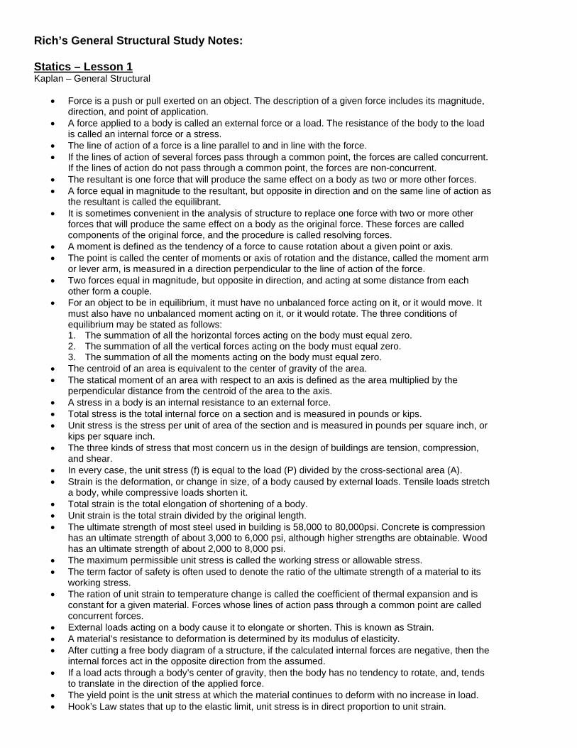
Rich’s General Structural Study Notes: Statics – Lesson 1 Kaplan – General Structural • Force is a push or pull exerted on an object. The description of a given force includes its magnitude, direction, and point of application. • A force applied to a body is called an external force or a load. The resistance of the body to the load is called an internal force or a stress. • The line of action of a force is a line parallel to and in line with the force. • If the lines of action of several forces pass through a common point, the forces are called concurrent. If the lines of action do not pass through a common point, the forces are non-concurrent. • The resultant is one force that will produce the same effect on a body as two or more other forces. • A force equal in magnitude to the resultant, but opposite in direction and on the same line of action as the resultant is called the equilibrant. • It is sometimes convenient in the analysis of structure to replace one force with two or more other forces that will produce the same effect on a body as the original force. These forces are called components of the original force, and the procedure is called resolving forces. • A moment is defined as the tendency of a force to cause rotation about a given point or axis. • The point is called the center of moments or axis of rotation and the distance, called the moment arm or lever arm, is measured in a direction perpendicular to the line of action of the force. • Two forces equal in magnitude, but opposite in direction, and acting at some distance from each other form a couple. • For an object to be in equilibrium, it must have no unbalanced force acting on it, or it would move. It must also have no unbalanced moment acting on it, or it would rotate. The three conditions of equilibrium may be stated as follows: 1. The summation of all the horizontal forces acting on the body must equal zero. 2. The summation of all the vertical forces acting on the body must equal zero. 3. The summation of all the moments acting on the body must equal zero. • The centroid of an area is equivalent to the center of gravity of the area. • The statical moment of an area with respect to an axis is defined as the area multiplied by the perpendicular distance from the centroid of the area to the axis. • A stress in a body is an internal resistance to an external force. • Total stress is the total internal force on a section and is measured in pounds or kips. • Unit stress is the stress per unit of area of the section and is measured in pounds per square inch, or kips per square inch. • The three kinds of stress that most concern us in the design of buildings are tension, compression, and shear. • In every case, the unit stress (f) is equal to the load (P) divided by the cross-sectional area (A). • Strain is the deformation, or change in size, of a body caused by external loads. Tensile loads stretch a body, while compressive loads shorten it. • Total strain is the total elongation of shortening of a body. • Unit strain is the total strain divided by the original length. • The ultimate strength of most steel used in building is 58,000 to 80,000psi. Concrete is compression has an ultimate strength of about 3,000 to 6,000 psi, although higher strengths are obtainable. Wood has an ultimate strength of about 2,000 to 8,000 psi. • The maximum permissible unit stress is called the working stress or allowable stress. • The term factor of safety is often used to denote the ratio of the ultimate strength of a material to its working stress. • The ration of unit strain to temperature change is called the coefficient of thermal expansion and is constant for a given material. Forces whose lines of action pass through a common point are called concurrent forces. • External loads acting on a body cause it to elongate or shorten. This is known as Strain. • A material’s resistance to deformation is determined by its modulus of elasticity. • After cutting a free body diagram of a structure, if the calculated internal forces are negative, then the internal forces act in the opposite direction from the assumed. • If a load acts through a body’s center of gravity, then the body has no tendency to rotate, and, tends to translate in the direction of the applied force. • The yield point is the unit stress at which the material continues to deform with no increase in load. • Hook’s Law states that up to the elastic limit, unit stress is in direct proportion to unit strain.
Transcript of Rich’s General Structural Study Notes: Statics – … Systems/structures...Rich’s General...
Rich’s General Structural Study Notes: Statics – Lesson 1 Kaplan – General Structural
• Force is a push or pull exerted on an object. The description of a given force includes its magnitude, direction, and point of application.
• A force applied to a body is called an external force or a load. The resistance of the body to the load is called an internal force or a stress.
• The line of action of a force is a line parallel to and in line with the force. • If the lines of action of several forces pass through a common point, the forces are called concurrent.
If the lines of action do not pass through a common point, the forces are non-concurrent. • The resultant is one force that will produce the same effect on a body as two or more other forces. • A force equal in magnitude to the resultant, but opposite in direction and on the same line of action as
the resultant is called the equilibrant. • It is sometimes convenient in the analysis of structure to replace one force with two or more other
forces that will produce the same effect on a body as the original force. These forces are called components of the original force, and the procedure is called resolving forces.
• A moment is defined as the tendency of a force to cause rotation about a given point or axis. • The point is called the center of moments or axis of rotation and the distance, called the moment arm
or lever arm, is measured in a direction perpendicular to the line of action of the force. • Two forces equal in magnitude, but opposite in direction, and acting at some distance from each
other form a couple. • For an object to be in equilibrium, it must have no unbalanced force acting on it, or it would move. It
must also have no unbalanced moment acting on it, or it would rotate. The three conditions of equilibrium may be stated as follows: 1. The summation of all the horizontal forces acting on the body must equal zero. 2. The summation of all the vertical forces acting on the body must equal zero. 3. The summation of all the moments acting on the body must equal zero.
• The centroid of an area is equivalent to the center of gravity of the area. • The statical moment of an area with respect to an axis is defined as the area multiplied by the
perpendicular distance from the centroid of the area to the axis. • A stress in a body is an internal resistance to an external force. • Total stress is the total internal force on a section and is measured in pounds or kips. • Unit stress is the stress per unit of area of the section and is measured in pounds per square inch, or
kips per square inch. • The three kinds of stress that most concern us in the design of buildings are tension, compression,
and shear. • In every case, the unit stress (f) is equal to the load (P) divided by the cross-sectional area (A). • Strain is the deformation, or change in size, of a body caused by external loads. Tensile loads stretch
a body, while compressive loads shorten it. • Total strain is the total elongation of shortening of a body. • Unit strain is the total strain divided by the original length. • The ultimate strength of most steel used in building is 58,000 to 80,000psi. Concrete is compression
has an ultimate strength of about 3,000 to 6,000 psi, although higher strengths are obtainable. Wood has an ultimate strength of about 2,000 to 8,000 psi.
• The maximum permissible unit stress is called the working stress or allowable stress. • The term factor of safety is often used to denote the ratio of the ultimate strength of a material to its
working stress. • The ration of unit strain to temperature change is called the coefficient of thermal expansion and is
constant for a given material. Forces whose lines of action pass through a common point are called concurrent forces.
• External loads acting on a body cause it to elongate or shorten. This is known as Strain. • A material’s resistance to deformation is determined by its modulus of elasticity. • After cutting a free body diagram of a structure, if the calculated internal forces are negative, then the
internal forces act in the opposite direction from the assumed. • If a load acts through a body’s center of gravity, then the body has no tendency to rotate, and, tends
to translate in the direction of the applied force. • The yield point is the unit stress at which the material continues to deform with no increase in load. • Hook’s Law states that up to the elastic limit, unit stress is in direct proportion to unit strain.
Beams and Columns – Lesson 2 Kaplan – General Structural
• A beam is a member that supports loads perpendicular to its longitudinal axis. • A simple beam is one that rest on a support at each end, and whose ends are free to rotate. • A cantilever beam is one that is supported at one end only, and which is restrained against rotation at
the end. • An overhanging beam is one that rests on two or more supports and has one or both ends projecting
beyond the support. • A fixed end beam is one that is retrained (fixed) against rotation at its ends. Some beams are fixed at
one end and simply supported at the other end. • Reactions are the forces acting at the supports that hold the beam in equilibrium. • A concentrated load acts at one point on the beam, while a distributed load acts over a length of the
beam. If the load per unit of length of the beam is constant, it is called a uniformly distributed load, or simply a uniform load.
• Simple and cantilever beams and overhanging beams that rest on two supports are statically determinate.
• Beams whose reactions cannot be found from the equations of equilibrium only, by require additional equations, are called statically indeterminate beams. Continuous and fixed end beams are statically indeterminate.
• The point where the moment changes from positive to negative is called the point of inflection. • A simple beam will have greater maximum moment and more deflection than either a continuous
beam or a fixed end beam supporting the same load on the same span. • The intersection of the neutral surface with the beam cross-section is a line called the neutral axis. • Deflection is the movement of a beam from its original location when load is applied to it. • A column is a member primarily subject to an axial compressive load. Sometimes a column also
resists bending moment; for example, if loads are applied off center (eccentrically), or perpendicular to its length, such as wind loads.
• When a column is subject to combined bending and axial compression, the compressive stress is P/A, and the flexural stress at the extreme fiber is Mc/I.
• The maximum stress that a column can resist without failing by buckling depends on the column’s unbraced length and section modulus.
• Bending moment in a beam is maximum at the point of zero shear. • The flexural stress in a beam is a function of the bending moment and the section modulus of the
beam. • The shear stress in a beam is maximum at the neutral axis. • The point where the bending moment in a beam changes sign is called the point of inflection. • A continuous beam having two equal spans supporting a uniformly distributed load over both spans:
1. The moment over the middle support is negative 2. The beam is statically indeterminate. 3. The moment at the end supports is zero. 4. The moment diagram for the two spans is comprised of parabolic curves.
• The flexural stress in a beam is uniform over the beam’s cross-section and is a function of the beams’ section modulus.
Wood Construction – Lesson 3 Kaplan – General Structural
• Three major elements: horizontal framing (joists, beams, and girders), vertical members (columns and walls), and the foundation.
• Species of trees are divided into two classes; hardwoods, which have broad leaves, and softwoods, which have scalelike or needlelike leaves.
• The greatest shrinkage occurs perpendicular to the grain, while the longitudinal shrinkage is usually negligible.
• Wood is much stronger in compression parallel to the grain(Fc) than perpendicular to the grain. • Notching of wood beams:
1. A gradual change in cross-section compared with a square notch increases the shearing strength nearly to that computed for the actual depth above the notch.
2. A beam notched or beveled on its upper side at the ends causes a less severe condition from the standpoint of stress concentration.
3. When notches are near the middle of a beam span, the net depth is used to determine bending strength.
• Glued laminated beams comprise an assembly of wood laminations in which the grain of all laminations is approximately parallel longitudinally, with the laminations bonded with adhesives.
• Glued laminated beams are usually loaded perpendicular to the wide faces of the laminations although occasionally, the load is applied parallel to the wide faces.
• Compared to sawn timbers, glued laminated members are more dimensionally stable, less subject to shrinkage and warping, and have greater strength and generally a more attractive appearance.
• Horizontal shear is especially critical for wood beams with short spans and large loads. • Longitudinal shrinkage, thermal shrinkage, and thermal contraction, are generally ignored in the
design and detailing of structural wood members. • Most lumber used structural is softwood and from coniferous trees. • Camber is often built into a glued laminated beam to avoid the appearance of sag, to eliminate the
ponding of water, and to compensate for deflection. • A notch near the middle of a beam’s span has practically no effect on its deflection. • The loss of shear strength caused by a gradual change in a beam’s cross-section is not as great as
that caused by a square notch. • The individual laminations are thin and therefore difficult to season before fabrication.
Steel Construction – Lesson 4 Kaplan – General Structural
• Corrosion requires the presence of both moisture and oxygen. There are a number of protective coatings that are used to resist corrosion, including paint, zinc (galvanizing), and concrete. Another method widely used to improve the corrosion resistance of steel is alloying, which is the addition of other elements, such as chromium, copper, and nickel.
• Although steel is incombustible, it lacks fire resistance. • All steel, regardless of its strength or other properties, has the same value of modulus of elasticity (E),
about 29,000,000 psi. • Ductility means the ability to absorb energy in the inelastic range, when the material is stressed
above its yield point, without failure. • The chemical composition of structural steel is: iron (over 98%), carbon (about one quarter of 1%),
and small quantities of other elements. The most important factor affecting the properties of steel is usually its carbon content; a small amount of carbon generally results in an increase in strength and a decrease in ductility. Most steels have a carbon content between 0.12 and 1.8 percent.
• The most widely used structural steel in the United States is referred to as ASTM A36 • For ASTM A36 steel, Fy = 36ksi • Compact, adequately braced, symmetrical members Fb = 0.66, Fy = 24ksi. The term compact is
defined very specifically, and practically all W and S shapes of A36 steel qualify as compact members.
• Doubly-symmetrical I and H shape members and solid bars bending about their weaker axis Fb = 0.57 Fy = 27.0ksi
• Tension for other flexural members Fb – 0.60 Fy = 22.0ksi • The compression flange of a steel beam is similar to a column. Its compressive stress tends to make
it buckle, just as a column tends to buckle under compressive load. • If lateral support is provided, the beam cannot buckle, and the full allowable bending stress may be
used. • The term composite beam refers to a steel beam and a concrete slab that are connected so that they
act together as a single structural unit to resist bending stresses. • Shear stress in steel beams:
1. The unit shear stress fv is equal to V/dt. 2. The shear stress should be checked for beams with a short span and a heavy load. 3. The shear stress should be checked for beams with a large concentrated load near the support.
• In designing steel columns, the larger slenderness ration is used because it results in a smaller allowable flexural stress.
• The carbon content of steel affects it strength and ductility. • The modulus of elasticity of steel has a constant value, is higher than that of any other structural
material, and is a measure of the stiffness of steel. • Wide flange steel shapes are symmetrical about both axes are is a very efficient structural member. • If the calculated deflection of a steel beam is excessive, it is necessary to select a different beam
section having a greater moment of inertia. • A composite beam consists of a steel beam and a concrete slab that act together to resist bending
stresses. • The shear stress between the steel beam and the concrete slab is usually resisted by the welded
studs. • In composite design, the concrete slab effectively becomes part of the beam’s top flange.
Reinforced Concrete Construction – Lesson 5 Kaplan – General Structural
• Reinforced concrete differs significantly in that concrete is strong in compression, but weak in tension. Hence, steel reinforcing bars are used to resist tensile stresses, while the concrete resists compressive stresses. Reinforced concrete beams are therefore unsymmetrical and non-homogeneous (they are composed of two materials, not one).
• Concrete is a mixture of aggregates (sand and gravel) held together by a paste made from Portland cement and water.
• ASTM provides for five types of Portland cement: 1. Type I is suitable for all normal uses. 2. Type II is used where precaution against moderate sulfate attack is important. It usually
generates less heat at a slower rate than Type I, especially important where the concrete is placed in warm weather.
3. Type III provides high early strength, usually in a week or less 4. Type IV is intended for use in massive concrete structures, where the rate and amount of heat
generated must be minimized. It develops strength at a slower rate than Type I 5. Type V is used only in concrete exposed to severe sulfate action.
• The most important factor that determines the strength of concrete is the water-cement ratio, usually expressed as the number of gallons of water per 94-pound sack of cement. The higher the water-cement ratio, the lower the concrete strength.
• The workability of concrete is measured in the field by the slump test of the Kelly ball test. • The principal way to measure the compressive strength of concrete is the cylinder test. • Sometimes, cylinders are tested after seven days, at which time their strength is about 60 to 70
percent of the 28-day strength. • The most common nondestructive test us the impact hammer test, in which the rebound of a spring-
loaded plunger is measured after it strikes a smooth concrete surface. • When concrete is loaded, it creeps – that is, it continues to deform with time, even if the load is not
increased. • The use of compressive reinforcement reduce the creep and hence the long-term deflection of the
beam and also reduces the possibility of any sudden failure. • Prestressed concrete is permanently loaded so as to cause stresses opposite in direction from those
caused by dead and live loads. • Compressive strength is measured by the cylinder test. • Water-cement ratio is the most important factor that determines the strength of concrete. • In prestressed concrete, smaller sizes may be used since the entire cross-section is effective in
resisting the applied loads. • In posttensioned members, the losses of prestress are usually less than in pretensioned members. • Spiral columns can support more load than tied columns, is all factors are the same. • Between the supports is where T-beam action in a two-span reinforced concrete beam is most
effective. • Compressive reinforcement is used when the concrete section is inadequate to resist the moment. • Compressive reinforcement in a reinforced concrete beam reduces the beam’s long-term deflection. • Compressive reinforcement reduces the possibility of sudden failure. • The cross-sectional area of compressive reinforcement is usually less than that of the tensile
reinforcement. • Compressive reinforcement is used where shear stresses are excessive.
Walls – Lesson 5 Kaplan – General Structural
• A bearing wall is one that supports vertical load in addition to it own weight. • A nonbearing wall is one that supports no vertical load other than its own. • A shear wall is one designed to resist lateral forces parallel to itself. • A retaining wall is one that resists the lateral displacement of soil or other materials. • As long as the slope (grade) does not exceed the natural angle of repose of the soils, it will remain
stable. • A gravity wall depends entirely on its own weight to resist the pressure of the retained earth and
provide stability. It is frequently constructed of plain (unreinforced) concrete. • The cantilever wall is the most common type of retaining wall, in which the stem, heel, and toe act as
cantilever slabs. • In the counterfort wall, the stem and base are connected at intervals by transverse walls called
counterforts, which act as tension ties to support the stem. This type of wall is more economical than the cantilever wall for heights over about 25 feet.
• The pressure exerted by the retained earth against the stem is known as active pressure. • Vertical load behind that wall or a sloping ground surface increases the earth pressure against the
wall, and both are known as surcharge. • For average conditions, with no surcharge, the active earth pressure may be assumed to be
equivalent to that exerted by fluid weighing 30 pounds per cubic foot. • A wall can fail by overturning. This occurs when the base is too narrow. • Reinforcing steel should be placed near the inside face of the wall (reinforced concrete). • A retaining wall is necessary whenever the ground elevation changes abruptly. • Tilt-up walls often function as deep beams spanning between footing pads. • Balloon framing is preferable where exterior walls are faced with brick veneer. • In balloon framing, the studs are continuous and full height, with the second floor joists bearing on a
continuous member that is let into the studs. • Reinforced brick masonry is generally stronger than concrete block masonry. • The grout used in reinforced masonry construction must have a minimum compressive strength of
2,000psi. • In reinforced concrete block construction, cells in contact with the earth should be filled solidly with
grout.
Connections – Lesson 7 Kaplan – General Structural
• Wood is stronger in bearing parallel to the grain than perpendicular to the grain. Therefore, the allowable load for certain fasteners depends on the angle of load to grain. The angle of load to grain is defined as the angle between the direction of the load acting on the member and the longitudinal axis of the member.
• The spacing of fasteners is the distance between centers of the fasteners measured on a straight line joining their centers.
• Edge distance is the distance from the edge of a member to the center of the fastener closet to that edge, measured perpendicular to the edge.
• Spilt rings are primarily used in the assembly of trussed rafters and trusses. • Shear plates are made of pressed steel, they are intended for wood-to-steel connections (using one
shear plate), or for wood-to-wood connections (using two shear plates). • Nails have greater value when driven into the side grain (perpendicular to the wood fibers) than into
the end grain of wood. Also, it is preferable that nails by used so that their lateral resistance (shear) is utilized, rather than withdrawal resistance.
• In bearing-type connections, made with either rivets or bolts, the members transfer load to the connector by bearing, while the connector resists the load by shear. The strength of the joint is therefore determined by the shear strength of the connector or the bearing strength of the member against the connector, whichever is lower.
• Slip-critical connections can only be made with high-strength bolts which conform to ASTM A325 or !490. In such connections, the bolts are tightened to a tension equal to 70% of their specified minimum tensile strength, thus tightly clamping the connected parts together.
• Joints, whether bearing-type or slip-critical, may be either single shear or double shear. • Welds – the depth of the base metal to the point where fusion stops is called penetration. • Fillet welds are placed in the right angle formed by lapping or intersecting plates and are generally
subject to shear stress. • Groove welds usually act in direct tension or compression and are placed between the two butting
pieces of metal to be joined. • In fillet welds, the stress is always considered to be shear stress on the minimum throat area
regardless of the direction of the applied load, where the throat area is 0.707 times the weld size. The allowable shear stress is 18.0 ksi for welds made with E60 electrodes and 21.0 ksi for welds made with E70 electrodes when the base metal is ASTM A36.
• AISC Weld Specifications require that the length, of a weld, must be at least equal to the perpendicular distance between welds.
• The following are factors to be considered in determining the allowable load for wood-to-wood mechanical fasteners:
o Lumber species o Fastener spacing and edge and end distances o Angle of load to grain and condition of loading.
• Connections subject to vibration – ASTM A325 slip-critical / ASTM 490 slip-critical. • Common bolts, shear plates, and split ring fasteners have the greatest strength for wood-to-wood
joints. • High-strength bolts are the most common fastener for steel-to-steel joints. • Fasteners have the greatest strength at 0 degree of angle to the wood grain.
Foundations – Lesson 8 Kaplan – General Structural
• The goal of foundation design is to limit the settlement to some small amount that is tolerable. To accomplish this, the foundation must be placed within a soil stratum of adequate strength, and the load must be spread over a sufficiently large area so as not to exceed the soil’s bearing capacity.
• The plate load test is used to determine the bearing capacity of a soil for static load on spread footings, and the pile load test, which is performed to check the design loads on piles.
• In general, rock is the best bearing material, while sands and gravels are good material, especially if they are compact and well-graded (containing a mixture of grains of various sizes). The fine-grained soils, such as silts and clays, may be satisfactory as foundation materials, nut require careful investigation. Organic soils, unconsolidated fills, and very soft or loose soils are generally unacceptable for the support of buildings.
• The proctor test is used to determine the soil’s optimum moisture content and density. • Properly compacted fill is often suitable for the support of building footings, floor slabs, walks, and
pavement. • Clay soils which swell when wet and shrink when dried, are called expansive soil. • Hydrostatic pressure – lateral and upward pressure caused by the water in the soil. • Single column footing – the required areas of the footing is found by dividing the total load, including
the estimated weight of the footing, by the bearing capacity of the soil. • A wall footing is a continuous spread footing supporting the vertical load on the wall, the weight of the
wall itself, and the weight of the footing. • It is good practice to provide some longitudinal reinforcing bars to help resist any longitudinal bending
caused by non-uniform loading or non-uniform soil conditions. Such bars are usually one or two #4 or #5, located near the top of the foundation wall and near the bottom of the footing.
• Cantilever footing – also known as a strap footing – consists of an exterior column footing joined by a concrete beam to an interior column footing.
• The mat foundation is essentially one large footing under the entire building, which distributes the load over the entire building area. Also called a raft foundation, it is used when soil conditions are poor.
• If the upper soils have insufficient bearing capacity to support spread footings, the building loads are often transmitted to deeper, firmer soils by piles.
• Piles may transfer the load to the soil by skin friction between the pile and the surrounding soil, or by end bearing, where the load is supported by the firm subsoil under the pile tip.
• Organic soil and unconsolidated fill, are unacceptable soil types to support buildings. • A single column footing is generally square in plan, with reinforcing steel near its bottom face. • Differential settlement is what is attempted to minimize in the designing of building foundations.
• Test borings are used to form the basis for the determination of a soil’s bearing. • Drilled piles transmit their load to the soil by skin friction. • Belled caissons transmit their load to soil by end bearing. • Single column footings have flexural reinforcing in two directions in the bottom face. • Increasing the thickness of the footing is a way to compensate for overstressed shear. • If the fill is removed and recompacted, it may be used to support building footings.
Conventional Structural System – Lesson 9 Kaplan – General Structural
• Dead load is the vertical load due to the weight of all permanent structural and non-structural components of a building, such as the walls, floors, roofs, and fixed service equipment.
• Line load is the load superimposed by the use and occupancy of the building, not including the wind load, earthquake load, or dead load. It includes the weight of people, furniture, supplies, etc., that are supported by the building’s structure.
• Building structures must be designed to resist wind load or earthquake load, but not both acting simultaneously.
• For water, the unit weight is 62.4 pounds per cubic foot. • Railings – For exit facilities serving an occupant load greater than 50, this load is 50 pounds per lineal
foot, and for all other railings, it is 20 pounds per lineal foot, according to the UBC. • If a slab is supported along two sides, it can only bend in one direction, and it is therefore called a
one-way slab. However, if the slab is supported along all four sides, it can bend in two directions simultaneously and is therefore known as a two-way slab. A two-way slab supports load more efficiently than a one-way slab, particularly if the spans in each direction are about equal.
• Simple beams are subject to positive moment only (compression at the top, tension at the bottom) and bend concave upward when loaded. Beam which are continuous across more than one span, however, are subject to negative moment over the supports and positive moment between the support.
• Continuous beams are statically indeterminate. • In rigid frame, the beam ends are restrained by the columns, making the beam more rigid and able to
resist greater vertical loads in bending. • The columns of a rigid frame are subject not only to compression, but also to bending moment
because of their rigid connections to the beam. • The base of a rigid frame requires horizontal forces, as well as vertical forces, to hold the frame in
equilibrium. • The rigid frame is able to resist horizontal loads in its own plane. • Lift slabs are most appropriate for multistory buildings with short spans and relatively light loads, as in
dormitories and apartment buildings. • Composite beam and T-beam structural systems consist of a flat element acting together with a deep
element to resist bending. • A rigid frame does not resist the load caused by a two-way flexural action. • A tapered girder has a profile which approximates its moment diagram. • Flexural members:
o Shear stress is often critical for short, heavily-loaded spans. o The two most important determinants of flexural stiffness are the depth of a member and its
material. o The further away a member’s material is from its neutral axis, the more efficiently it can resist
bending. • In rigid frames, both beams and columns must resist bending and axial load. • For conventional office buildings, the structural cost is roughly 25% of the total construction cost. • Compared to a simple beam, a continuous beam has greater negative moment. • A live load reduction is not permitted in a place of public assembly • A live load reduction is permitted only when the member supports more than 150 sq. ft. • Stiffness and strength are not the same. Stiffness means resistance to deflection, while flexural
strength is the ability to resist bending stress.
Long Span Structural Systems – Lesson 10 Kaplan – General Structural
• According to the AIA Long-Span Building Panel, 60 feet for an office building is a long span. Sixty feet for a gymnasium is not a long span.
• Standard open web steel joist are tabulated up to a span of 60’, long spans up to 96’, and deep longspan joist up to a span of 144’.
• Rolled beams are available up to 44” in depth, and their economical span limit is generally around 80’.
• Where longer spans or heavy loads occur, rolled beams of the required size are often unavailable or uneconomical. In such cases, built-up members known as plate girders may be used instead. These girders comprise an assembly of plates, or plates and angles, which are welded or bolted together to form an integral member.
• Since a plate girder is built up from component parts, it is relatively easy to vary its cross section to provide the maximum section modulus where the bending moment is maximum (generally at the midspan), and conversely, the minimum section modulus where the bending moment is minimum, which is usually at the supports.
• For long spans and/or heavy loads, trusses are often more economical than beams and girders. • A Vierendeel truss, named after its Belgian inventor, is one without diagonals. • Three standard series of open web joists are available: K, LH, and DLH. The K series vary in depth
on 2” increments from 8” to 30”, the LH series from 18” to 48” in increments of 2” to 4”, and the DLH series from 52” to 72” in 4” increments.
• A 16K7 refers to a 16” deep joist of the K series with number 7 chord sections. • In pretensionsing, high strength steel wires are tensioned between abutments in a casting yard before
placing the concrete in the beam forms. The concrete is then placed, and after the concrete has attained adequate strength, the prestress wires are cut. This transfer the tensile force in the wires as a compressive force to the concrete by bond and friction along the steel strands.
• In posttensioned construction, the concrete is cast with a hollow conduit or sleeve through which the prestressing wires are passed.
• The prestress losses caused by friction, elastic shortening, and shrinkage are generally less than with pretensioning.
• The single T is used for spans up to 100’ or more. The double T is probably the most popular cross section used in this country. A flat surface is provided, usually four feet in width, and spans usually do not exceed 60’.
• When the spans in both directions are approximately equal, a two-way system is often more efficient than a one-way system.
• The shallower depth of the two-way system results in less wall area, reduced building volume, and consequently, lower construction and operating costs.
• Cantilevers reduce the positive moment resisted by the main members, resulting in less material and reduced deflection.
• Arch supports may be hinged or fixed. Hinged supports permit the arch base to rotate, while fixed supports do not. Hinged arches are flexible, and do not develop high bending moments caused by temperature changes or foundation settlement; fixed arches, on the other hand, are more rigid and develop high bending stresses under temperature variations or soil settlement. Some hinged arches have an additional hinge at the high point, or crown of the arch. Such arches, called three-hinged arches, are statically determinate, and find their widest application in glued laminated arches.
• A pure arch is one that is stressed only in compression, without any bending when supporting a load. • When an arch is loaded, it requires a horizontal reaction at its base. Without this horizontal force,
called the arch thrust, the arch would spread outward and collapse. The thrust is usually resisted either by a tension tie rod connecting the base or by an abutment.
• Arch ribs are individual arches connected by elements that span between them, such as curved concrete slabs. A vault is essentially a series of arches placed side by side to form a continuous structure.
• Pioneered by the brilliant Italian engineer Pier Luigi Nervi, the lamella roof structure consists of a series of parallel arches that are skewed with respect to the axes of the building, and that intersect another series of skewed arches.
• The arch tends to spread outward at its base, resulting in inward acting horizontal thrust. The cable tends to pull its support inward, resulting in outward-acting horizontal thrusts. The rise of an arch may be compared to the sag, or drape of a cable. And just as steep arches have small thrusts, cable with a deep sag have small thrusts.
• When an arch is subjected to changing loads, it develops bending moments; but a cable cannot resist any bending moment since it can only resist tension. A cable therefore responds to changing loads by changing it shape.
• The tension in a cable is related to its sag: the greater the sag, the lower the tension. A large sag increases the length of the cable, but decreases its tension and hence its required cross-sectional area.
• A rectangular frame acts primarily in flexure, while a gabled frame has less bending but more compression.
• The advantage of a rigid frame over a simple beam supported by columns (post and beam) is he frame’s greater ability to resist both vertical and horizontal loads.
• A shell, or thin shell, is a structure with a curved surface that supports load by compression, shear, or tension in its own plane, but which is too thin to resist any bending stresses.
• The oldest long span structures were arches, domes, and vaults. • Exposed structural steel is often used for long span roofs used to enclose arenas and stadiums. This
is possible because building codes permit unprotected steel construction when the roof is high above the floor.
• Steel girders are efficient bending members because most of their material is in the flanges. • Secondary stresses in trusses are; often ignored; bending and shear stresses caused by joint
restraint; and necessary to consider when designing primary trusses spanning long distances. • The joist designation 18LH06 indicates it is a longspan steel joist, its depth is 18”, and its top chord is
section number 06. • Glued laminated beams:
o The wood species is generally Douglas Fir or Southern Pine o They are more dimensionally stable than sawn timber beams o They are stronger than conventional sawn timbers.
• A two-way truss system is efficient when the spans in both directions are about equal. • The bases of an arch are subject to a horizontal thrust. • A cable responds to changing loads by changing its shape. • A hyperbolic paraboloid:
o Can be formed by a series of straight lines. o Is a very stiff structure. o Is economical in the use of material. o Is curved downward in one direction and upward in the other.
Trusses – Lesson 11 Kaplan – General Structural
• The word truss denotes a structure designed to support vertical or horizontal loads and composed of straight members that form a number of triangles.
• The perimeter members of a truss are called chords. The interior members connecting the chords are called web members, or more specially, diagonals or vertical, depending on their direction. Any truss member not necessary for stability is called a redundant member.
• In a parallel chord truss, the forces in the chords increase toward the center of the span, just as in a beam, the flange forces increase toward the center.
• The shear in a beam is resisted by shear stresses in the web, while the shear in a truss is resisted by the tensile or compressive force in the web members, depending on their direction.
• After the forces in all the truss members have been determined, either graphically or analytically, the truss members are design. Compression members are designed as columns, and tension members must have sufficient new area.
• Although they require relatively complex fabrication and great depth, trusses are often economical framing members.
• In a bowstring truss, where the depth varies from a minimum at the supports to a maximum at midspan, the chord forces are relatively constant across the entire span.
• A redundant member is a truss member that is not necessary for stability. • A trussed rafter is a type of lightweight prefabricated truss that is in widespread use. • A stress diagram is a method or diagram used to solve a truss graphically. • Double angle compression members in a steel truss may be designed on either the r(x-x) or r(y-y).
Notable Building and Engineers – Lesson 12 Kaplan – General Structural
• Pantheon – the largest dome of the ancient world, was built by the Romans in the year 123 A.D. Since the Romans had no material that were strong in tension, their solution was to make the dome walls about 20 feet thick at the bottom, in order to keep the unit tensile stresses low enough to be resisted by the concrete. To reduce the weight of the dome, its underside was coffered.
• Hagia Sophia in Constantinople (now Istanbul), completed in 537 A.D. – Its architects, Anthemius and Isidorus. Its main dome was shallow and supported by four pillars, through pendentives and arches that rose from the pillars.
• The dome of Santa Maria del Fiore in Florence, designed by the great Renaissance architect Filippo Brunelleschi, and completed in 1436; understood that a dome tends to spread apart, and built in a series of circumferential iron chains to act as tension rings and hold the dome in equilibrium.
• Crystal Palace – designed by Joseph Paxton, it was more that a third of a mile long, enclosed nearly a millions square feet, and was fabricated and erected in only six months.
• In the Yale University Skating Rink, designed by Eero Saarinen and completed in 1958, steel cables are hung from a central reinforced concrete arch.
• Palazzetto Dello Sport designed by Pier Luigi Nervi for the 1960 Rome Olympics; its roof, a ribbed concrete shell dome, is supported by 36 Y-shaped concrete buttresses which resist the forces at the edge of the shell.
• The principal structural materials utilized by Wright in Fallingwater are cast-in-place concrete and masonry.
• The John Hancock Building, in Chicago, (SOM) expresses its structure through its tapered form and its enormous exposed cross-bracing is effective in resisting wind loads.
• The Toronto City Hall (Viljo Revell) is comprised of two huge shells which are curved to provide resistance to wind or earthquake loads.
• The Sears Tower (SOM with Fazlur Kahn – engineer) exemplifies the bundled tube concept. • The Federal Reserve Bank Building (Gunnar Birkerts) clearly expresses its catenary suspension
structure. • Munich Olympic Stadium – Frei Otto
Principles – Unit 1 Kaplan – General Structural Test Bank
• A long-span structure which consists of top and bottom chords and only vertical web members is
called a vierendeel truss. • A space frame is a two-way truss system. • A lamella is a two-way skewed arch system. • A Warren truss has diagonal web members which alternate direction. • A thin shell structure is able to resist shear, tension, and compression. • Hooke’s law defines the relationship between unit stress and unit strain. Hooke’s Law states that up
to the elastic limit, unit stress (P/A) is directly proportional to the unit strain. In other words, if a load of 10,000 pounds causes a member to stretch x inches, then a load of 20,000 pounds will stretch the member 2x inches.
• Strain and deformation mean the same thing, that is, the change of length which a member undergoes as a result of stress.
• Live load is defined as: the load caused by the use and occupancy of the building, not including wind, earthquake, or dead loads.
• The engineer who was best known for the tubular design of high-rise buildings such as the Sear Tower and John Hancock Building, both in Chicago, was Fazlur Khan. These buildings behave essentially as hollow steel tubes which cantilever from the foundation when subject to wind load.
• Pier Luigi Nervi created soaring concrete shell roofs. • Felix Candela is famous for his thin shell concrete structures. • Shear failure of a glued laminated beam is most likely to occur near the supports and within a
lamination close to the mid-height of the beam. • Shear failure of a beam is most likely to occur where the vertical shear is maximum, which is adjacent
to a support. Horizontal shear stress in a beam varies from zero at the outermost fibers to a maximum value at the mid-height of the beam. Furthermore, since the glue is generally stronger than the wood, failure is more likely to occur with a lamination than between the laminations.
• Stress is defined as an internal resistance to an external force. • An exterior force that acts on a body is a load. • The change in size of a body caused by an external force is strain or deformation. • The tendency of two members to slide past each other is shear. • Buckling caused by lateral instability of a steel beam’s compression flange can be eliminated by using
a section which has the same moment of inertia about each axis and by providing lateral support for the compression flange.
• When a steel beam resists bending moment, one flange is in compression either the other is in tension. The compression flange (the top flange in the case of a simple beam) is similar to a column, that is, its compressive stress tends to make it buckle laterally. If lateral support for the compressive flange is provided, buckling is prevented. Another way to prevent buckling, although not general economical, is to use a section which is equally stiff about both axis, such as a square tube. The tendency to buckle is then resisted by the lateral stiffness of the member.
• Making a beam deeper or adding web stiffener plates does not necessarily eliminate buckling. • The amount that a member expands because of a rise in temperature depends on the amount of
temperature change, the length of the member, and the coefficient of thermal expansion of the material.
• All material expand when they are heated and contract when they are cooled. The amount of this thermal expansion or contraction is the product of three factors: the amount of temperature change in degrees F, the length of the member in inches, and the coefficient of thermal expansion of the material.
• The ability of a material to deform non-elastically in tension without rupture is termed ductility. Structure steel is an example of the ductile material.
• Plasticity refers to the capacity of a material to be molded or worked into shape. • The ability of a material to return to its original shape after being deformed is called elasticity. • Rigidity refers to a material’s resistance to deformation. • The strength of a structure steel column depends:
o On the unbraced length of the column. o The radius of gyration of the column cross-section o The end conditions of the column o The yield stress of the steel
• The strength of a structural steel column depends on Fy, • Punching shear is the tendency of a column to punch through its supporting footing, two-way shear,
and is investigated at a distance d/2 from the face of the column. • A column supported by a footing tends to punch through the footing because of shear stresses which
act in the footing around the perimeter of the column. The shear is a two-way action, and is calculated through the footing around the column on a perimeter a distance d/2 from the faces of the column.
• The other type of shear that occurs in footings is on-way or beam shear, which is calculated at a distance d from the face of the column. This is not punching shear.
• In testing a ductile material, the stress at which it continues to deform without an increase in load is called the yield point.
• A rigid frame is a frame in which the joints are rigid and capable of transferring bending moment between the members.
• A rigid frame, which is usually structural steel or reinforced concrete, is one in which the members are rigidly connected to each other so that bending moment can be transmitted between the members. A rigid frame can resist horizontal loads in its own plane as well as greater vertical loads than a simple non-rigid frame. A rigid frame may have either fixed or hinged bases, and a rigid frame can more laterally.
• The traditional Early Christian basilican churches were generally distinguished by timber trusses roofs.
• Buttresses and pointed arches did not generally appear in church design until the Medieval period. • Vaulted naves, as well, were developed somewhat later in ecclesiastical history. • Moment of inertia is a measure of the stiffness of a beam. It is the resistance to deflection, • Section modulus (S) is a measure of the bending or flexural strength of a beam. • Modulus of elasticity (E) determines the stiffness of a material, or its resistance to deformation. • Ductility refers to a material’s ability to deform without rupture. • The resultant is a force which will produce the same effect on a body as two or more other forces and
it may be determined either analytically or graphically. It may also be described as the vectorial sum of the forces acting on a body.
• Equilibrant, a force equal in magnitude to the resultant, but opposite in direction.
• In a parallel chord truss, the chord forces increase toward the center of the span. • The forces in the web members decrease toward the center of the span. • Intra-panel loads result in combined bending and direct stress. • A truss is analogous to a steel beam; in a parallel chord truss, the chord forces increase toward the
center of the span, just as in a beam, the flange forces increase toward the center. And just as the web shear in a beam decreases toward the center of the span, similarly the forces in the web members of a truss decrease toward the center. Sometimes, loads are applied to the top or bottom chord between the panel points; such intra-panel loads result in bending in the chord member, in addition to the axial stress caused by truss action.
• The change of length of a member caused by a rise or fall in temperature depends on the member’s material and the amount of temperature change, and the length of the member.
• As a rule of thumb, the average structural cost for buildings is about 25% of the total cost of construction. For buildings with minimal architectural and mechanical requirements, such as warehouses, the structural cost may be 50% or more of the total cost of construction.
• In a homogeneous rectangle beam subject to negative moment, the greatest stress is at the top and bottom edges.
• A composite beam consists of a steel beam and a concrete slab which are adequately connected so that they act together as a single structural unit to resist bending stresses. The stress between the steel beam and the concrete slab is shear and is resisted by shear connectors, such as studs, welded to the top flange of the beam and embedded in the concrete.
• The Parthenon, a masterpiece of Greek architecture, was adapted from wood construction of early Greek temples to marble. Its post-and-beam structure is appropriate for wood, bu not stone, whose low tensile strength limits its ability to span as a beam. The Romans, not the Greeks, exploited the great compressive strength of stone and concrete to span great distances with vaults, domes, and arches.
• Subtle visual adjustments were made to the Parthenon to correct for optical illusions. Among these was entasis, a slight convexity of the columns, so that they would not appear concave.
• The German architect Frei Otto pioneered the design of cable-supported roofs. For the Olympic Stadium in Munich in 1972, he designed a huge tent covering 80,000 sq. ft. and supported by nine masts and boundary prestressing cables.
• Hooke’s Law states: Unit stress is directly proportional to unit strain, up to the elastic limit. • Many of the Roman structure would have been impossible to construct without the use of groined
vaults. This ingenious development accomplished all of the following: o It concentrated the thrust of the vaults at the four corners of the vaulting bay. o It enabled large windows to be inserted high up under the arches of the vaults. o It enabled the timber centering used for one bay of the vaulting to be dismantled and used
again. • If a cable supports vertical loads which are distributed evenly along the length of the cable, it
assumes the shape of a catenary. If the loads were evenly distributed horizontally, then its shape would be a parabola.
• Positive moment is – Moment which causes the upper beam fibers to be in compression and the lower beam fibers in tension.
• Simple beams supporting downward loads have positive moment across the entire span. Moment which causes the upper beam fibers to be in tension and the lower fibers to be in compression is negative moment.
• Cantilever beams resisting downward loads have negative moment along their entire length. • The Sears Tower, in Chicago, consists of a bundle of nine steel tubes. • The John Hancock Building is Chicago is a trussed tube which expresses its structure through its
tapered form and enormous exposed exterior X-bracing. • The Water Tower Building, in Chicago, is one of the tallest reinforced concrete building in the world. • The property of a material that causes it to return to its original length when load is removed is termed
Elasticity. • At any point in a beam, the horizontal and vertical shear stresses are equal, the shear stress in a
beam varies from zero at the edges to a maximum at the neutral axis, and the shear stress in a simple beam supporting vertical loads is maximum at the supports.
• Deflection of a steel beam is affected by the moment of inertia of the beam, the span of the beam, and the load on the beam.
• Prestressed concrete is permanently loaded so as to cause stresses opposite in direction from those caused by dead and live loads. The combined effect of the prestress and the dead and live loads usually results in compression over the entire cross-section of a beam, eliminating tension cracks and allowing a smaller section to be used. Prestressing also reduces diagonal tension stresses at working

loads. However, creep and shrinkage of the concrete are not eliminated by prestressing and their effects must be considered in the design of prestressed members.
• Dead load is the load caused by the weight of all permanent structure and nonstructural components of a building.
• In theory, an ideal column is one for which the buckling tendency is equal in both direction. This occurs when the radius of gyration r in the x-x direction is equal to r in the y-y direction. This also means that the moment of inertia (I) is equal in both directions. These conditions are met by pipe columns and square steel tubes. In actual practice, pipe columns and square steel tubes are not widely used because of the difficulty of making adequate beam connections.
• The pressure exerted by retained earth against a retaining wall is called active pressure. • Fluid pressure refers to the lateral pressure exerted by a fluid, not earth. • Passive pressure is the resistance to the movement of a retaining wall provided by the earth in front
of a wall and footing. • Surcharge pressure is the increased lateral earth pressure against a retaining wall caused by a
vertical load behind the wall or a sloping ground surface.
Codes and Regulations – Unit 2 Kaplan – General Structural Test Bank
• No reduction of live load is permitted for places of public assembly since there will be times when
such spaces actually experience the full design live load because of crowding. • Live loads greater than 100 psf are required for storage, library stack rooms and other similar uses,
and it would not be prudent (or legal) to reduce the live load in such cases. • The earthquake zone affects the seismic forces acting on a building, not the live loads. • If an occupancy is hazardous it may require greater fire resistance, but it has no effect on live load. • For a retaining wall, the dead load resisting moment must be at least 1.5 times the overturning
moment. • The live loads prescribed by the building code are minimum live loads. If the actual live load is greater
than the value specified by the code, the actual live load must be used in the design.
Materials and Technology – Unit 3 Kaplan – General Structural Test Bank
• All material expand when heated and contract when cooled. The amount of expansion or contraction
is equal to the product of three quantities: the coefficient of thermal expansion, the length of the member, and the temperature change.
• A lamella roof structure is a series of parallel arches which are skewed with respect to the axes of a building and which intersect another series of skewed arches.
• The allowable axial compressive stress for a steel column is based on its slenderness ratio K1/r, where K is the effective length factor, which depends on the end condition of the column, 1 is the effective length of the column, and r is the radius of gyration, a property of the column cross-section. Since the value of K varies from less than 1 to greater than 1, the effective length of the column K1 may be less or more than 1, the actual length. A column with fixed ends has less tendency to buckle than one with pinned ends and therefore has a low value o K and a high allowable axial compressive stress.
• A spiral column can support more axial load than an otherwise identical tied column. • The reinforcing in a spiral column is always arranged in a circular pattern. • Reinforced concrete columns have longitudinal reinforcing bars close to the concrete face and are
designated by the type of lateral reinforcement provided for these bars. Tied columns have widely-spaced ties around the longitudinal reinforcing, while spiral columns have the longitudinal bars arranged in a circle and wrapped with a closely-spaced steel spiral. Because of the superior performance of spiral columns, they have a greater axial load capacity than tied columns having the same area and reinforcing. Forming and fire resistance are unaffected by whether the column contains ties or spirals.
• In order to identify high-strength bolts which conform to ASTM A325, certain standardized markings are used. In this regard the following apply:
o The bolt head is identified by the legend A325 o The bolt head may be marked with three radial lines 120 degrees apart. o The standard nut marking consists of three circumferential marks spaced 120 degrees apart.
• Heavy hex structural bolts which conform to ASTM A325 are identified on the top of the head by the legend “A325” and the manufacturer’s symbol. At the option of the manufacturer, the bolts may be marked with three radial lines 120 degrees apart.
• Open web steel joist: The top chords may be pitched one or two ways to provide sufficient slope for roof drainage, the joist are actually simply supported uniformly loaded trusses, and exposed joists are incombustible but have no fire-resistance rating.
• Open web steel joist are standardized, lightweight steel truss which generally support uniform loads from floor or roof decks. They may have parallel chords or single or double pitched top chords to provide for roof drainage. The joist have no fire-resistance rating by themselves, but ratings of one hour of more may be obtained by using the proper floor or roof deck and ceiling. Open web steel joist are always fabricated in the shop.
• Two types of reinforced concrete columns are in general use: tied columns and spiral columns. Tied columns are usually square or rectangular in cross-section and contain longitudinal reinforcing bars with separate lateral ties. Spiral columns are square or round in shape and have longitudinal reinforcing bars arranged in a circle and enclosed by a closely-spaced steel spiral. The ACI Code, which is the basis for most reinforced concrete design in this country, permits larger loads on spiral than on tied columns when loaded concentrically because of the greater toughness of spirally reinforced columns.
• The purpose of belling the bottom of a caisson is to provide sufficient bearing area to resist the applied vertical load.
• Belled caissons are frequently used when the soils near the surface are relatively poor, but are underlain by dense soils having a high bearing value. A vertical shaft is drilled into the earth; when the bearing stratum is reached, a special belling attachment is used to enlarge the hole to form a bell having a diameter of up to three times that of the drilled shaft. Sometimes the final enlarging of the bell is done by hand.
• Spirals and ties are not combined, since the ties would serve no purpose. All columns must be designed to resist a specified minimum amount of moment, and may never be designed to resist zero moment. The ties prevent the longitudinal bars from buckling and help to confine the concrete, but spacing the ties closer together does not increase the axial load capacity.
• Composite construction is economical because of the savings in beam weight. • A composite beam is a steel beam and a concrete slab which are connected so that they act together
as a structural unit to resist bending stresses. Composite construction is most efficient with heavy loads and relatively long spans and may utilize steel and concrete materials of various strengths/
• Composite construction is often economical because it allows lighter weight steel beams to be used. However, there savings must be compared with the additional labor and material costs of the shear connectors which are added to the steel beams.
• Piles may be made of timber, concrete, or steel. • Piles should be spaced no closer than three diameters center to center. • The allowable upward load on a pile is generally less than the allowable downward load. • Piles are essentially columns that transmit load to the underlying soil by bearing, skin friction, or both.
Piles are made in a variety of shapes and materials, including timber, concrete, and steel. • To be effective, piles should not be spaced so close together that the earth between them losses its
supporting capacity; a minimum spacing of three diameters center to center is often specified. • In most cases, the bearing capacity of a group of piles is less than that of a single pile multiplied by
the number of piles in a group. • Since the uplift resistance of a pile is based only on skin friction, it is usually less than its downward
capacity. • The cost of concrete construction can generally be reduced by making beams wider than columns,
and, by making all columns the same size and vary the amount of reinforcement. • Since forming represents the largest cost in reinforced concrete construction, the use of standardized,
reusable forms tends to make concrete construction economical. • Making beams wider than columns is economical because it minimizes congestion by allowing corner
beam bars and column bars to clear each other. Also, the forming is simpler than is the beams were narrower than the columns. One should use the largest, not the smallest, bar size that will meet design requirements, because a smaller number of larger bars is less expensive to place than a larger number of small bars.
• The strength of wood is greater parallel to the grain than perpendicular to the grain. • Some materials, such as steel, are isotropic – that is, they have the same strength in all directions.
Wood is not isotropic, since it is much stronger parallel to the grain than perpendicular to it. • Wood is generally stronger in compression than in tension. • All ¾” diameter structural steel bolts do not have the same capacity in shear.
• Bolt capacity is determined by the size and type of steel of the bolt, and the thickness and type of steel of the connected sections.
• The capacity of a steel botl is determined by its strength in shear and bearing. Its shear strength is based on the bolt size and steel type (ASTM specification), and its bearing strength is based on the bolt size, the thickness of the connected parts, and the steel type (ASTM specification) of the connected parts. Therefore, ¾” diameter bolts can have different shear capacities.
• Field welding may be specified when it is appropriate, and may be used for various connections, including those that transfer load. Welding, not high strength bolting, is sometimes inspected by ultrasonic techniques, to determine if flaws exist within the weld which are not visible.
• Bridging or blocking is used between wood joist to help distribute concentrated loads and to provide lateral support for the joists.
• Wood joists are actually deep narrow beams, which tend to be laterally unstable. Bridging or blocking is therefore used to prevent rotation or lateral displacement. The bridging or blocking also helps to distribute concentrated loads to the adjacent joist.
• Although fire stops are required between wood studs, they are not usually specified between joists, and bridging would be ineffective for the purpose anyway.
• In the design of flexural reinforced concrete members the amount of reinforcing steel must be less than that which would produce balanced design.
• Virtually all reinforced concrete is designed by the strength design method, in which the internal stresses and strains in a reinforced concrete beam which is about the fail are used to determine the ultimate moment capacity of the member. If crushing of the concrete and yielding of the reinforcing steel take place simultaneously, it is called balanced design. It is desirable to keep the amount of reinforcing steel relatively small, so that if the member should ever be overstressed, it will fail gradually by yielding of the steel, rather than crushing of the concrete, thus providing adequate warning. For this reason, the amount of reinforcing is limited to 75% of that which would produce balanced design.
• All of the following are appropriate for steel-to-steel connections subject to stress reversal or fatigue loading; fillet welds, groove welds, and ASTM A325-SC bolts.
• Steel connections that are subject to significant stress reversal, fatigue loading, or any other condition where slip would be detrimental, are termed slip-critical and must be made with high-strength bolts conforming to ASTM A325 or A490.
• Fillet or groove welds could be used for such connections. • Lag bolts are used for wood-to-wood or wood-to-steel connections, not for steel-to-steel connections. • The main purpose of a base plate under a structural steel column is to distribute the column load over
a sufficient area, to avoid overstressing the concrete foundation in bearing. • The concrete foundation supporting a steel column is relatively weak in bearing. Therefore, a steel
base plate must be used to spread the column load over a large area and thus avoid overloading the concrete. The area if the base plate Is determined by the column load and the allowable bearing pressure on the concrete support. The thickness is found by considering the portions beyond the column to be steel slabs which cantilever from the edges of the column.
• Open web steel joist – an 18J5 joist usually has the same depth and configuration as an 18H5 joist. • Steel used for J-series joists has a yield strength of 36,000 psi, while chord sections of H-series joist
have a yield strength of 50,000psi. • H-series and J-series joists may use either hot-rolled or cold-formed chords. • Open web steel joists are open web parallel chord members that are completely standardized as to
length, depth, and carrying capacity, and are suitable for the support of both floors and roofs. They may utilize either hot-rolled or cold-formed steel. H- and J-series joists are virtually identical, except that the H-series joists are comprised of higher-strength steel and therefore have greater load-carrying capacity. Both H- and J-series joists are often provided with top chord extended ends, which are used for short cantilevers.
• The deflection of a structural steel beam is affected by the load supported by the beam, the span of the beam, and the moment of inertia of the beam section.
• Deflection is the movement which a beam undergoes when subjected to load. The amount of deflection is determined by four factors: the loads acting on the beam, the stiffness of the beam material (measured in modulus of elasticity), the beam’s moment of inertia, and the span of the bema. Inelastic material such as wood and concrete deflect when the load is initially applied and then continue to deflect with time without any increase in load. Structural steel, on the other had, behaves elastically – it does not deflect more than its initial deflection unless the load is increased.
• The yielding point of the steel, is a measure of the beam’s strength, but not is stiffness. All steel, regardless of strength, has the same stiffness, as measured by its modulus of elasticity.

• Bolts joining wood members have greatest capacity when the load acts parallel to the grain, and their capacity when the load acts perpendicular to the grain. When the load acts at any other angle to the grain, the bolt capacity may be determined by using Hankinson’s Formula, and the value thus obtained is less than that parallel to the grain and greater than that perpendicular to the grain.
• When a bolt acts perpendicular to the grain of a wood member, the capacity of the bold is less than that of a bolt acting at an angle of 45 degrees to the grain.
• A framing system which consists of story-high trusses spanning transversely between exterior columns and arrange so that the floor system spans from the bottom chord of one truss to the top chord of the next is called a Staggered truss system.
• Most rigid frames will move sideways when subject to either horizontal or vertical load, or both. Two exceptions: when the structure is restrained from horizontal movement, and when the frame is symmetrical and subject to a symmetrical vertical load.
• A flat plate, two-way system transmits its load directly to the supporting columns without thickened slabs or widened columns. It is most appropriate for residential and other lightly-loaded uses with fairly short spans. It is inappropriate for warehouses and industrial building because of their heavy loads.
• The size of a pad footing is determined by the load and the allowable soil bearing pressure and not by the building’s height. If piles are used each column may be supported by a group of piles, and the load is distributed from the column to the piles by a pile cap. In that care, there is not usually a pile directly below each column.
• There are two basis methods by which concrete is prestressed: pretensioning and posttensioning. In the pretension method, the steel is tensioned before placing the concrete (the prestressing strands are tensioned between abutments prior to placing concrete in the beam forms). Posttensioning involves tensioning the steel after the concrete is placed (prestressing wires are placed in a hollow sleeve in the beam and tensioned after the concrete is placed and has acquired it strength).
• Glued laminated beams my be manufactured in virtually any length, and thus transportation from the plant to the job site is the only limitation on length. A glued laminated beam can be made with better quality lumber in the outer, more highly stressed areas, and therefore higher allowable stresses can be obtained than with sawn lumber. Because the members can be longer and have higher allowable stresses, framing layouts with longer spans may be used. However, with longer spans, deflection becomes a more significant consideration. Even with the same beam size,span, and loading, a glued laminated beam will deflect about the same amount as a sawn wood beam. Thus, deflection is at least as significant in a glued laminated member as in a sawn wood member, and if longer spans are used, deflection becomes even more significant.
• For a roof which has a column-free space of 200 feet in both directions, a space frame system would be economical.
• A space frame is a two-way grid of trusses, connected at all panel points, which can efficiently spane column-free spaces.
• A Vierendeel truss is a truss with no diagonals and is not generally economical. • Rigid frames, although widely used in building construction, would not be economical for a 200-foot
span. • A framing system which is appropriate for large circular areas consists of a series of radial cables.
The center tension ring is lower than the perimeter. • For a cable to be stressed in tension, the center must be lower than the perimeter; if the cable were
higher, the cable would be stressed in compression, which it is unable to resist. Each cable pulls on the center ring, which stresses it in tension.
• The difference between a tied and a spiral reinforced concrete column is the type of lateral reinforcement.
• There are two types of reinforced concrete columns: spiral columns and tied columns, which differ in the kind of lateral reinforcement they utilize. Spiral columns enclose the longitudinal reinforcing bars with a closely-spaced continuous steel spiral, which braces the longitudinal bars and confines the concrete. Tied columns have separate lateral ties which hold the longitudinal bars in position, prevent them from buckling outward, and also somewhat confine the concrete.
• The flat slab system is most economical for heavy loads and square bays. • The flat slab is a two-way reinforced concrete floor system which brings its load directly to supporting
columns without any beams or girders, usually requiring column capitals (widened tops of columns) and drop panels (thickened slab around the columns). Since it is a two-way system, it is most efficient for bays which are square or almost square. The flat slab system is most appropriate and economical for building with heavy loads, such as warehouses and industrial plants.
• When a glued laminated member is 12 inches or less in depth, the full allowable stress may be used for design. For depths greater than 12 inches, a size factor is used, which has the effect of reducing the allowable stress that may be used.
• Temperature steel is reinforcement that provides for temperature stresses. • Building codes require that reinforcement for shrinkage and temperature stresses normal to the
principal reinforcement must be provided in the structural floor and roof slabs, where the principal reinforcement extends in one direction only. Such reinforcement is often called temperature steel.
• A flat slab is a two-way system appropriate for square bays. A flat slab is a reinforced concrete slab which spans in two directions without beams or girders. Because it is a two-way system, a flat slab is appropriate for bays which are approximately square.
• Reinforced concrete floor framing systems: o In a pan joist floor system, shear stress near the support is often a controlling factor. o A reinforced concrete slab 10 feet by 25 feet in plan is usually assumed to span in the 10 foot
direction only. o The concrete floor framing system requiring the simplest formwork is the flat plate floor. o Slab band construction requires more beam reinforcement than a conventional beam used
for the same span and loading conditions. • A pan joist system consists of concrete joists formed by removable metal pans, generally 20 or 30
inches wide and 6 to 11 inches deep; this system is usually economical for light loads on fairly long spans. It can be thought of as a solid concrete slab, with the concrete eliminated where is is not required to resist moment.
• While shear is seldom critical in the design of a solid concrete slab, the joist system eliminates so much concrete that shear near the supports often becomes a controlling factor. To provide additional shear resistance, special tapered end pans are often used.
• All slabs with perimeter supports span in both directions. However, most of the load is carried by the shorter span, and when the ratio of long span to short span is 2 to 1 or greater, the amount of load supported in the long direction is neglected, and the short span is assumed to carry the load.
• A flat plate floor system is a girderless floor without thickened drop panels or flared column capitals. It therefore requires the simplest framework of any concrete framing system.
• A slab band is simple a wide, shallow beam supporting a one-way slab. Because of its shallowness, the slab band requires more reinforcement than a conventional, deeper beam.
• In a glued marinated beam, if different lamination grades are used, the higher grade laminations should generally be used at the top and bottom, where the flexural stresses are maximum.
• In most cases, glued laminated beams are manufactured from more than one lamination grade. The higher grades are generally used at the top and bottom of the beam cross-section, where the flexure (bending) stresses are maximum.
• Loads applied to a truss chord between panel points result in combined bending and axial stress in the chord member.
• When loads are applied at the panel points of a truss, where the truss members intersect, the stresses in the truss members are axial tension or compression. However, if loads are applied between the panels points, the chord must be designed to resist the resulting bending mement as well as the axial stress caused by the truss action.
• All of the following are advantages of welding over bolting: • Decrease in the weight of steel • Less required detailing • Saving of time • Welding results in a decrease in the weight of steel because of the simplicity of the joints and the
utilization of the full section with no deduction for the bolt holes. Less detailing of the fabrication is required, and there is a saving of time, since less preparation is needed than for bolting. However, welding may be more susceptible to brittle fracture and fatigue, although resulting structural failures are rare.
• Compression steel is used in reinforced concrete beams to increase the load-carrying capacity of shallow beams.
• Sometimes a reinforced concrete beam is too shallow to resist the applied moment. In that case, reinforcing steel may be embedded in the compression face of the beam to increase its moment capacity. The use of compressive reinforcement reduces the long-term deflection of the beam, but not its initial deflection. Compressive reinforcement has little effect on the amount of tensile steel required and no effect on the number of stirrups needed.
• Wood systems are generally the lightest structural systems, reinforced concrete systems are the heaviest, and structural steel systems are in between. For a 100 psf live load, the live-load to dead-
load ratios are roughly as follows: wood joist – 15; open web steel joist – 3; flat slab – 1; and composite steel beams – 2.
• Flat slabs are economical in formwork and for heavy live loads. • A flat slab is a concrete slab which is reinforced in two directions and brings its load directly to the
supporting columns, generally without any beams or girders. Flat slabs are relatively thin and therefore not economical in reinforcing steel, but economical in formwork. For heavy live loads and bays which are approximately square, flat slab construction is often economical.
Environmental Issues – Unit 4 Kaplan – General Structural Test Bank
• When a column is located very close to the property line, a square or a belled caisson would extend beyond the property line, and would therefore not be acceptable. A combined footing, which would support both the exterior and interior columns, might be a good solution. Another approach would be a cantilever footing, which consists of an exterior column footing within the property line joined by a concrete beam to the interior column footing. A strap footing is another name for a cantilever footing.
• Reinforcing steel must be placed in the tension face of a reinforced concrete structure, that is, the face which elongated or stretches under load. Thus, by visualizing the shape of the deflected structure, one can determine where the reinforcing steel should be placed.
• The design of retaining walls considers overturning, sliding, and the allowable soil bearing pressure. • A retaining wall holds back the soil behind it, in much the same way that the water behind a dam is
held back. The lateral pressure from the soil tends to overturn the wall and to make it slide. In designing the wall to resist the soil pressure, the footing must be made wide enough so that the allowable soil bearing pressure is not exceeded.
• The specifications for compacted fill generally include the required density, moisture content, and the lift thickness.
• Soils used for backfill or for support of pavements or structures are compacted to increase their strength and stability. Samples of soils to be compacted are obtained and subjected to laboratory compaction tests, such as the Proctor test, to determine optimum moisture content and desity. These vary, depending on the soil type. The specifications for compacted soil generally include: the density required, as a percentage of optimum laboratory density, moisture content limits, above and below optimum moisture content, and lift thickness, which is the thickness of each layer of soil to be compacted.
• In building foundations settlement – total settlement is generally less critical than differential settlement; settlement of granular soils, such as sand, occurs immediately after loading, and to minimize differential settlement, footings should be proportioned for equal unit pressures under dead load.
• All buildings settle to a greater or lesser degree, and many buildings can tolerate a relativiely large settlement, provided that it is uniform. Non-uniform, or differential settlement can often cause damage. Since the dead load usually produces the greatest amount of settlement, proportioning footings so that the dead load bearing pressure under all the footings is the same will minimize differential settlement. Settlement does not occur at the same rate for all soils. For sand and other granular soils, settlement occurs immediately after loading, while fir plastic soils, such as clays, settlement may continue for months or years.
• Good engineering practice calls for the resultant to fall within the middle third of the base. The soil pressure diagram is trapezoidal, or triangular if the resultant is exactly at the 1/3 point of the base. If the design is such that the resultant falls outside the middle third, the simplest solution is to make the base wider.
• Retaining walls are designed to resist the lateral pressure of the retained earth. This pressure is generally assumed to increase linearly from the top to bottom.
• Retaining walls are generally designed for pressure equivalent to that exerted by a fluid weighing 30 pounds per cubic foot. This pressure varies linearly from zero at the top to a value at the bottom equal to 30 pounds per cubic foot multiplied by the depth in feet.
• Weep holes are provided to drain the retained earth, but cannot reduce the pressure to zero.
Final Examination Kaplan – General Structures
• For reinforced concrete columns the area of longitudinal reinforcement must be at least 1% of the cross-sectional area of the column.
• The impact hammer test is used to determine the strength of hardened concrete. • At advantages of continuous beams over simple beams include less defection and lower moment. • During the construction documents phase of a project, it is determined that the calculated deflection
of a steel beam is excessive. The best way to remedy this situation is to use a beam with a greater moment of inertia.
• ASTM A307 machine bolts are generally not used in a moment steel frame. • A pile cap is a thick reinforced concrete slab that distributes load to a group of piles. • The load capacity of a structural steel column is a function of K1/r. K is a constant determined by the
degree of fixity at the ends of the column. K is a constant that depends on the buckled shape of the column at failure. An increase in the value of K results in a decrease in the column load capacity.
• The ultimate 28-day strength of the concrete affects the shear capacity of a reinforced concrete beam.
• The ratio K1/r is a measure of the buckling tendency of a steel column; the larger the value of K1/r. the greater the tendency of the column to buckle, resulting in a lower column capacity.
• Excessive shear stresses in reinforced concrete beams cause diagonal cracks to form in the beam. Resistance to shear stresses is provided by the concrete and by shear reinforcement, usually in the form of stirrups. The shear resistance of the concrete is determined by the ultimate 28-day strength of the concrete, and the width and depth of the beam. The longitudinal tension reinforcing does not resist shear stresses. Likewise, the aggregate size and the beam span have no effect on the beam’s shear capacity.
• For steel columns: o The maximum slenderness ratio permitted is 200 o The K factor is used to convert the actual length of the column to the effective length. o The buckling tendency of a column is independent of its yield point value.
• Steel column base plates are designed to spread the column load so that the bearing pressure on the foundation is not excessive.
• Wood screws have greater holding power than nails of the same diameter. • Wood screws may not be driven with a hammer. • Connections in which wood screws are subject to withdrawal loads should be avoided it possible. • The principal reason that high-early-strength cement is used is because early removal of forms
shortens the construction period. • The ideal column to resist buckling is one whose radius of gyration is the same in both directions,
such as a pipe column, and not a wide flange section. • The moment at the interior supports of a continuous beam is always negative when the beam
supports normal downward vertical loads. • For concentrated column loads, the most common type of footing is a square pad centered beneath
the column, which results in a uniform soil pressure on the footing. However, if the column is located adjacent to a property line, the footing cannot be centered beneath the column, and the eccentricity between the center of the column and the center of the footing results in a non-uniform soil pressure distribution. This could result in undesirable footing settlement, or an uneconomically large footing. To avoid these problems, a cantilevered footing is often used, in which the grade beam between the two pad footings resists the bending caused by the footing eccentricity.
• Steel columns generally bear on steel base plates, which spread the column load over the foundation, so that the allowable bearing pressure is not exceeded.
• A column with a typical base plate is usually considered to be pin-ended, not fixed against rotation. Any shear in the column is usually transmitted to the foundation by anchor bolts, not friction.
• Although connections that are subject wood screws to withdrawal loads are permissible, it is better to avoid them if possible.
• Loading screws in withdrawal from the end grain of wood is not permitted at all. • There are five types of Portland cement: • Type III (high-early-strength) is generally used to speed the construction process. Such cement is
more costly than normal cements, but achieves high strength in one to three days. A given concrete strength can be obtained with any type of cement, and all types of cement are readily available.
• For a body to be in static equilibrium: o The sum of the forces acting in any direction is equal to zero.
o The sum of the moments about any axis is equal to zero. o The resultant force is equal to zero.
• The modulus of elasticity of concrete increases as the concrete strength increases. • The ratio of unit stress to unit strain for a material is a measure of its stiffness. • Reinforced concrete:
o The code provisions assure that yielding of the tensile steel will occur before failure of the concrete.
o The depth of the rectangular stress block (a) is less than the distance from the extreme compression fiber to the neutral axis.
o For a singly reinforced beam, the steel is assumed to resist all the tensile stresses and the concrete is assumed to resist all the compressive stresses.
• The difference of bending moments between two sections of a beam is equal to the area of the shear diagram between those two sections.
• The maximum unit shear stress in a beam occurs at the neutral axis. • Glued laminated members:
o With proper quality control, the adhesive is at least as strong as the wood. o The individual laminations are thin enough to be readily seasoned before fabrication. o The members may be varied in cross-section along their length in accordance with strength
requirements. • Glued laminated members generally shrink less than sawn timber members. • Shrinkage in wood is generally greater in heavier pieces than in lighter pieces of the same species. • Shrinkage is usually greater in hardwoods than in softwoods. • Where wood joists are supported from a steel beam by joist hangers, the tops of the joist when
installed should be above the top of the beam to provide for shrinkage of the joist. • Stirrups in a reinforced concrete beam are used as web reinforcement, where the concrete is
overstressed in shear. • Slenderness ratio is the ratio of the effective length of a column to its least radius of gyration. • Slump test is used to measure the workability of concrete. • If the backfill is paced before the first floor is constructed, the wall must be temporarily braced to
resist earth pressure. • The roof of a circular building is supported by a series of radial arch-shaped ribs, which connect to a
ring at the center of the roof and to another ring at the perimeter. The center ring is in compression and the perimeter ring is in tension.
• A waffle slab is a two-way system without beams, and generally formed with removable dome-shaped steel forms.
• A three-hinged gabled frame: • Its supports permit rotation. • The moment at the center is zero. • The maximum moment occurs at the intersection of the column and the sloping beam. • In general, concentrated loads are best resisted by a truss. • The required number of rows of bridging for open web steel joists is a function of the chord size and
span only, not the load. • A Vierendeel truss is one without diagonals. Therefore, large openings, such as doors and windows,
may be made within the depth of a Vierendeel truss without conflicting with diagonal members. However Vierendeel trusses tend to have greater deflection and more material than conventional triangulated trusses. While the joints of a Vierendeel truss may appear simple, they are not nessarily so, since they must be designed to transfer moment.
• A waffle slab is a two-way ribbed slab that generally does not require any beams. It is usually formed using dome-shaped steel forms which are removed after the concrete has hardened.
• A three-hinged gabled frame, or arch, is a statically determined structure. The hinges at the supports and center permit rotation and therefore can develop no moment. The maximum moment occurs at the haunch, the intersect of the column and the clopping beam, but this moment is generally less than in a rectangular rigid frame.
• The lack of redundancy is long span structures makes them more vulnerable to general collapse in case of accidental overload than short span structures.
• The potential consequences of failure of long span structures are greater than for conventional structures.
• Systems that adequately brace short spans may not be stiff enough for long span structures. • Framed domes are frequently constructed with a center ring to simplify erection and alleviate
congestion of framing members.
• Dead load is defined as the weigh of all the permanent structural and nonstructural components of a building.
• A membrane adapts to changing loads by changing its shape. • The supports of an arch may be either fixed or hinged. • Long span – The size of an arena roof depends partially on the size of its central floor space, and the
indoor sport that requires the largest such space is hockey. • The main reason for tapering a girder is to provide for adequate bending strength where it is needed. • The Parthenon – Its members were adapted from wood to stone. • Steel joist – The load carrying capacities may be determined directly from the Standard Specifications
of the Steel Joist Institute; open web steel joists may be used in spans greater than 100 feet; when selecting steel joists, consideration must be given to both load carrying capacity and deflection.
• Trusses are generally expensive to fabricate, but usually require less material than competitive systems.
• Truss members are most often designed for axial stress only. • A series of inclined trusses that intersect in a grid pattern and are connected at their points of
intersection is known as a space frame. • In multi-story rigid frames made of cast-in-place concrete, continuity at the beam-column joints is
provided by the monolithic nature of the concrete and proper lapping of the reinforcing bars.