
RFNT_CDR
38
Radio Frequency Navigational Tracker
-
Upload
matthew-sharp -
Category
Documents
-
view
31 -
download
2
Transcript of RFNT_CDR

Radio Frequency Navigational Tracker

Main Objective Create a vehicle that will track a
high frequency RF/IR transmitter
The practical application is a golf caddy that will follow a golfer when requested.
Matthew Sharp

Platform
Processor
Motor
DigitalCompass
Motor (Right)
GPIO
RS/232 Base of Vehicle
Transmitter
IR TX
RF TX
GPIO
Digital Compass
Motor (Left)
MotorControlGPIO
RS/232
RF RX
Hardware Overview
IR RX

Transmitter
Ben Says: “It Transmits!!”
Matthew Sharp

RF Transmission
Matthew Sharp

IR TX
Matthew Sharp

Receivers
Matthew Sharp

RF RX
Matthew Sharp

IR RX
Simple, yet sophisticated!!
Matthew Sharp
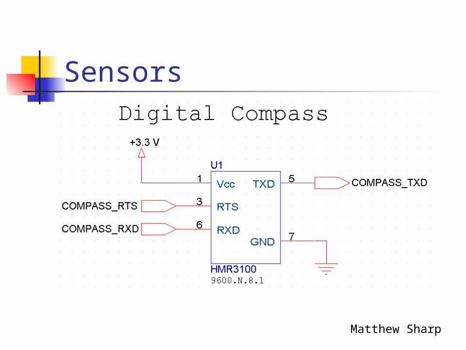
Sensors
Matthew Sharp

Timing is Everything
Matthew Sharp

8051 to the Rescue
Matthew Sharp

Powering the Transmitter
Fabien Nervais

Base Motors
Two 12V ServoDisk Motors
Power – 12V Car Battery Optocoupler Solid-State Relays 4 Amp Fuses
Fabien Nervais

Rotating Mount Configuration
5V DC Servo Motor
Grooved Rubber Belt
Power 12V to 5V linear
voltage regulator Solid-State Relay
Fabien Nervais
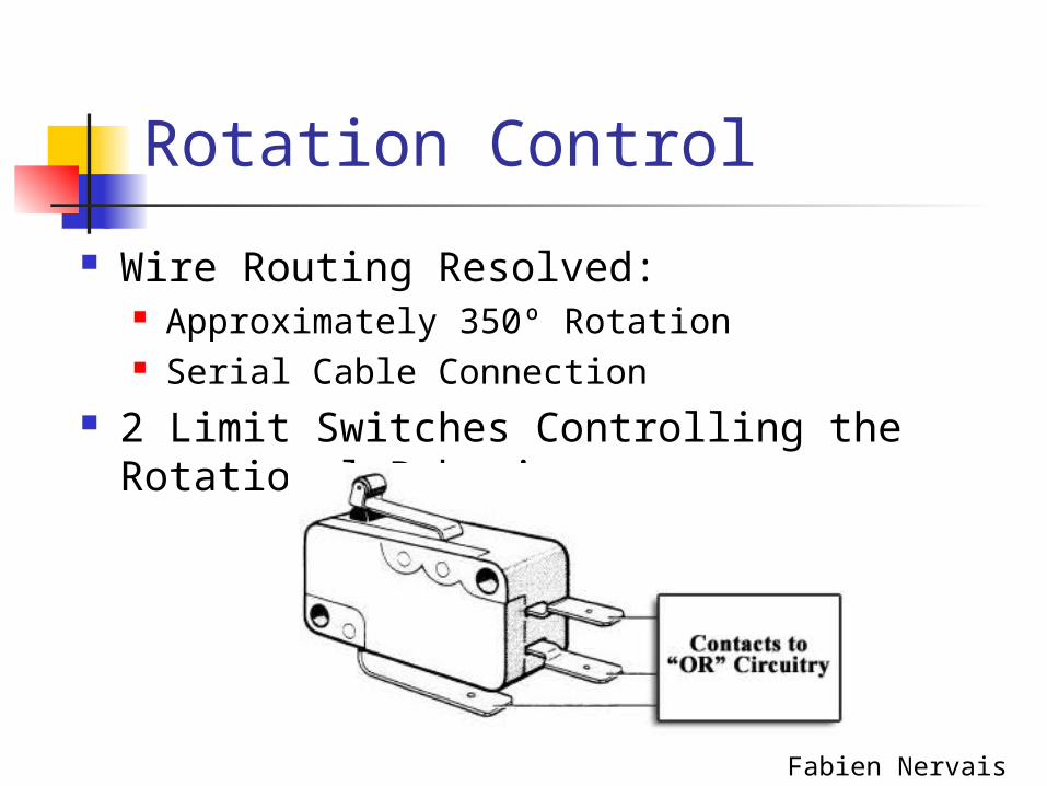
Rotation Control
Wire Routing Resolved: Approximately 350º Rotation Serial Cable Connection
2 Limit Switches Controlling the Rotational Behavior
Fabien Nervais

Powering the Rotating Mount Platform
Fabien Nervais

Processor
Ryan Hitchler

System Clock
Ryan Hitchler

Capacitors and Vcc/Gnd Bus
.1 uF
Vcc Gnd
Ryan Hitchler

Headers
Ryan Hitchler

Memory
Ryan Hitchler
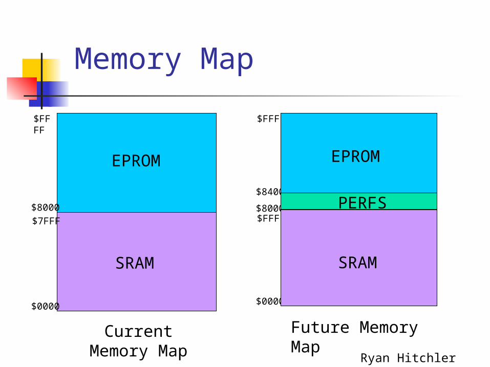
Memory Map
$0000
$FFFF$8000
$8400
$FFFF
EPROM
SRAM
PERFS
$FFFF
$0000
$7FFF
$8000
EPROM
SRAM
Current Memory Map
Future Memory Map
Ryan Hitchler

Power
Ryan Hitchler
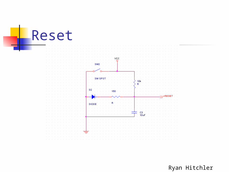
Reset
Ryan Hitchler
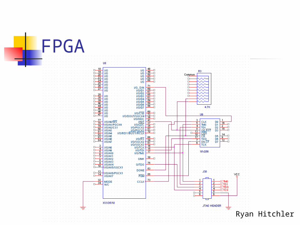
FPGA
Ryan Hitchler
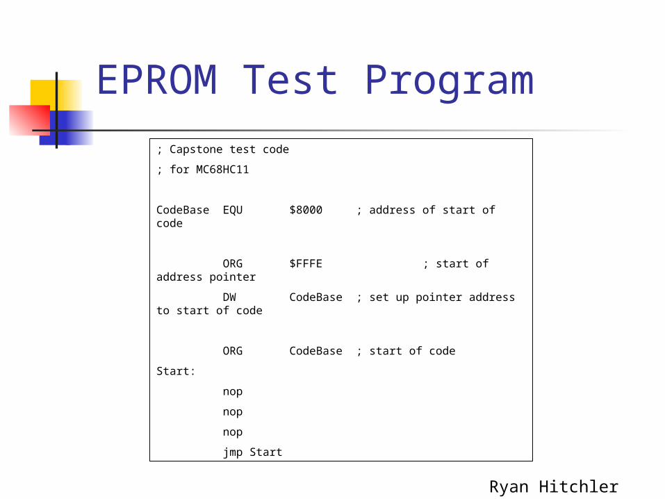
EPROM Test Program
; Capstone test code
; for MC68HC11
CodeBase EQU $8000 ; address of start of code
ORG $FFFE ; start of address pointer
DW CodeBase ; set up pointer address to start of code
ORG CodeBase ; start of code
Start:
nop
nop
nop
jmp Start
Ryan Hitchler

EPROM Test Results
Ryan Hitchler

Parts ListingPart Quantity Price.1 uF Cap 28 Donated1 uF Cap 2 DonatedThrough Hold Pins 26 DonatedPower Bus 2 DonatedRaltron 8MHz Clk Oscillator 1 DonatedHeat Sink 1 DonatedLM7805 5V Regulator 1 Donated78M33 3.3V Regulator 1 DonatedBanana Plug (Female) 3 DonatedLED (Yellow) 1 DonatedDiode 1 DonatedVarious Resistors 3 DonatedSPST Switch 1 DonatedPush Button Switch 1 DonatedXCS10 FPGA 1 Donated18V256 EEPROM 1 Donated10 Pin 4.7KOhm SIP 3 Donated6 Pin JTAG Header 1 Donated20 Pin Logic Analyzer Header 2 Donated27C256 EPROM 1 Donated62256 SRAM 1 Donated28 Pin ZIF 1 DonatedMC68HC11 E0 1 Donated74373 Transparent Latch 1 DonatedMAX233 2 DonatedDB9 Connector 2 DonatedPerf Board 1 $19.00Stand Off 10 $10.00Total Cost $29.00 Ryan Hitchler

Power On RF Signal
?
Set up Interrupts
Set up Serial
Poll RF Receiver
No
Turn Antenna
Poll IR Receiver
IR Signal
?
No
Yes
Yes
Stop Antenna
Read Ant. Compass
Turn Base -> Ant
Base =
Ant.?
Read Base Compass
No
Stop Turning
YesTurn Ant. -> Base
Read Ant. Compass
Ant. = Base
?No
Stop Antenna
Move Base
Yes
IR Signal
?
Poll IR Receiver
No
Yes
Poll RF Receiver
RF Signal
?
YesNo
John Maitin
Software Algorithm Redux

Code
; Capstone algorithm code; for MC68HC11
; begin code sectionORG CodeBase ; start of code
Start:lds #Stack ; load stack pointerbsr enable_int ; enable interrupts
pollrf:ldaa PORTA ; get GPIO informationanda #RFMASK ; mask out RF informationcmpa #RFMASK ; compare to RF informationbne pollrf ; if no RF signal, continue polling
startantenna:ldaa PORTA ; get GPIO informationoraa #MAONFMASK0 ; mask in antenna motor control infoanda #MAONFMASKF ; mask out unwanted infostaa PORTA ; write out GPIO stuff
pollir:ldaa PORTA ; get GPIO informationanda #RFMASK ; mask out RF informationcmpa #RFMASK ; compare to RF informationbne stopantenna ; jump to stopantenna if no RF signal foundldaa PORTA ; get GPIO information againanda #IRMASK ; mask out IR informationcmpa #IRMASK ; compare to IR maskbne pollir ; if no IR signal, continue polling
stopantenna:ldaa PORTA ; get GPIO informationoraa #MAOFFMASK0 ; mask in antenna motor control infoanda #MAOFFMASKF ; mask out unwanted info
antennacompass: oraa #CMPAMASK ; select antenna compass staa PORTA ; write out GPIO information bsr read_compass ; read from the antenna compass into d std compass ; store antenna compass reading into compass
baseturn: ldaa PORTA ; get GPIO information anda #CMPBMASK ; select base antenna staa PORTA ; write out GPIO information bsr read_compass ; read from the base compass into d subd compass ; subtract compass value beq movebase ; if equal, then move base cpd $0167 ; compare d to halfway value for compass bge turnright ; turn right if difference greater than halfway
turnleft: ldaa PORTA ; get GPIO information oraa #MLONRMASK0 ; write in left motor information anda #MLONRMASKF ; write out unwanted information staa PORTA ; write GPIO information ldaa PORTA ; get GPIO information oraa #MRONFMASK0 ; write in right motor information anda #MRONFMASKF ; write out unwanted information staa PORTA ; write GPIO information bra pollcomp1 ; jump to pollcomp1
John Maitin

Code (Pt. 2)
turnright: ldaa PORTA ; get GPIO information oraa #MLONFMASK0 ; write in left motor
information anda #MLONFMASKF ; write out unwanted
information staa PORTA ; write GPIO information ldaa PORTA ; get GPIO information oraa #MRONRMASK0 ; write in right motor
information anda #MRONRMASKF ; write out unwanted
information staa PORTA ; write GPIO informationpollcomp1:
movebase: stop
; enable interrupt controlenable_int: sei ; disable interrupts ldaa #$30 ; 9600 baud, assuming 8 MHz clock staa BAUD ; ldaa #$00 ; 8 data bits staa SCCR1 ;
ldaa #$2c ; Receive interrupt, poll transmit, enable TX,RX
staa SCCR2 ;
ldaa SCSR ; clear RDRF, error flags ldaa SCDR ; clear receive buffer
clra ; clear a tap ; transfer a to cc register (enable XIRQ and IRQ) cli ; enable interrupts rts
; SCI interrupt handlerrec: psha ldaa SCSR anda #$40 cmpa #$40 bne quit ldaa SCDR staa compassquit: pula rti
; change antenna direction (XIRQ interrupt handler)changeant: psha pshb ldaa PORTA ldab antdir comb bmi goreversegoforward: oraa #MAONFMASK0 anda #MAONFMASKF bra finishchangegoreverse: oraa #MAONRMASK0 anda #MAONRMASKFfinishchange: staa PORTA pulb pula rti
John Maitin

Simple Memory Map, Simple Decode
Memory map is divided in half, so only 1 pin needed to decode
If memory mapped I/O is used, we can adapt logic with and gates from needed address pins
Josh Bingaman

Motor Control Decoding
Josh Bingaman

RS232 Multiplexing
Josh Bingaman

Sensor Communication All GPIO No Decode logic 1 pin for IR Reception 1 pin for RF Reception Limit Switches on Antenna motor to
XIRQ 1 spare GPIO input for Proximity
SensorJosh Bingaman


QUESTIONS?


