RF Linac for High-Gain FEL - USPASuspas.fnal.gov/materials/14UNM/B_Photoinjectors.pdf · RF Linac...
32
LA-UR 14-23995 RF Linac for High-Gain FEL Photoinjectors Dinh Nguyen, John Lewellen and Leanne Duffy Los Alamos National Laboratory US Particle Accelerator School June 16-20, 2014
Transcript of RF Linac for High-Gain FEL - USPASuspas.fnal.gov/materials/14UNM/B_Photoinjectors.pdf · RF Linac...
LA-UR 14-23995
RF Linac for High-Gain FEL
Photoinjectors
Dinh Nguyen, John Lewellen and Leanne Duffy
Los Alamos National Laboratory
US Particle Accelerator School
June 16-20, 2014

LA-UR 14-23995
1. Components of a Photoinjector
2. Photoemission
3. Intrinsic Emittance
4. Space Charge
5. Emittance Compensation
6. DC Gun
7. NCRF Gun
8. SRF Gun
9. Invariant Envelope
10. Booster
2

LA-UR 14-23995 3
A photoinjector has the following major components:
• ELECTRON GUN (either DC or RF) that accelerates electrons from rest
• PHOTOCATHODE that releases picosecond electron bunches when irradiated with the optical pulses from a modelocked laser
• DRIVE LASER to gate the emission of electrons from the photocathode
• BOOSTER to accelerate the electrons exiting the gun to sufficiently high energy to mitigate space charge emittance growth.
• HV or RF SOURCE such as a klystron to power the electron gun.
In this section, we focus on the generation of high-brightness beams in a photocathode electron gun. We briefly study three different designs of electron guns: DC, normal-conducting RF and super-conducting RF. We also explore the emittance compensation theory and how to match the electron beams into the booster to obtain minimum normalized emittance.

LA-UR 14-23995 4
Gun Technologies
• DC Gun
• Normal-conducting RF Gun
• Super-conducting RF Gun
Cathode Technologies
• Thermionic cathodes
• Photocathodes
• Metal
• Semiconductor
Booster Technologies
• Normal-conducting Booster
• Super-conducting Booster
What cathode gradient is needed to obtain the required normalized emittance?
What are the required bunch charge and repetition rate?
What is the photocathode intrinsic emittance at the laser photon energy (this determines the photoemission radius at the cathode)?
What are the FEL wavelength and final electron beam energy?
What is the electron beam’s peak current exiting the booster (this and the final peak current determine the required bunch compression ratio) ?

LA-UR 14-23995 5
Metal photocathodes
• Copper, magnesium, lead, niobium
• Require UV photons (>4.5 eV)
• <10-4 quantum efficiency
• Short penetration depth (~14 nm)
• Prompt electron emission
Semiconductor photocathodes
• Cesiated antimonide, GaAs, telluride
• Require visible or UV photons
• >10-2 quantum efficiency
• Long penetration depth (~mm)
• Delayed electron emission
Three steps of photoemission: • Electron excitation • Electron transport to surface
• Electron escape
Transport Escape
Material
Laser hn
Work function or Bandgap
Excitation
Vacuum
Potential is lowered by the applied field
classical escape over the barrier
electron-electron scattering electron-phonon scattering
Penetration depth

LA-UR 14-23995 6
Cu photocathode Q.E.
K2CsSb photocathode Q.E. BNL/Jefferson Lab
Quantum efficiency is defined as the number of electrons emitted divided by incident number of laser photons.
Electron bunch charge (in coulomb)
where W = laser pulse energy (J)
= photon energy (eV)
..EQW
Q
from Dave Dowell
LA-UR 14-23995 7
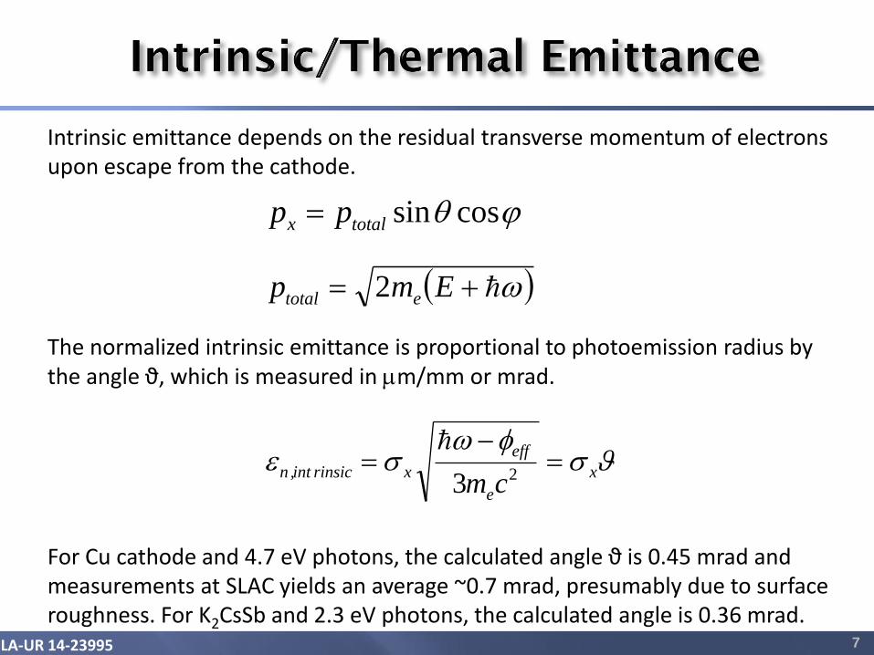
Intrinsic emittance depends on the residual transverse momentum of electrons upon escape from the cathode.
The normalized intrinsic emittance is proportional to photoemission radius by the angle ϑ, which is measured in mm/mm or mrad.
For Cu cathode and 4.7 eV photons, the calculated angle ϑ is 0.45 mrad and measurements at SLAC yields an average ~0.7 mrad, presumably due to surface roughness. For K2CsSb and 2.3 eV photons, the calculated angle is 0.36 mrad.
cossintotalx pp
x
e
eff
xrinsicint,ncm
23
Emp etotal 2
LA-UR 14-23995 8
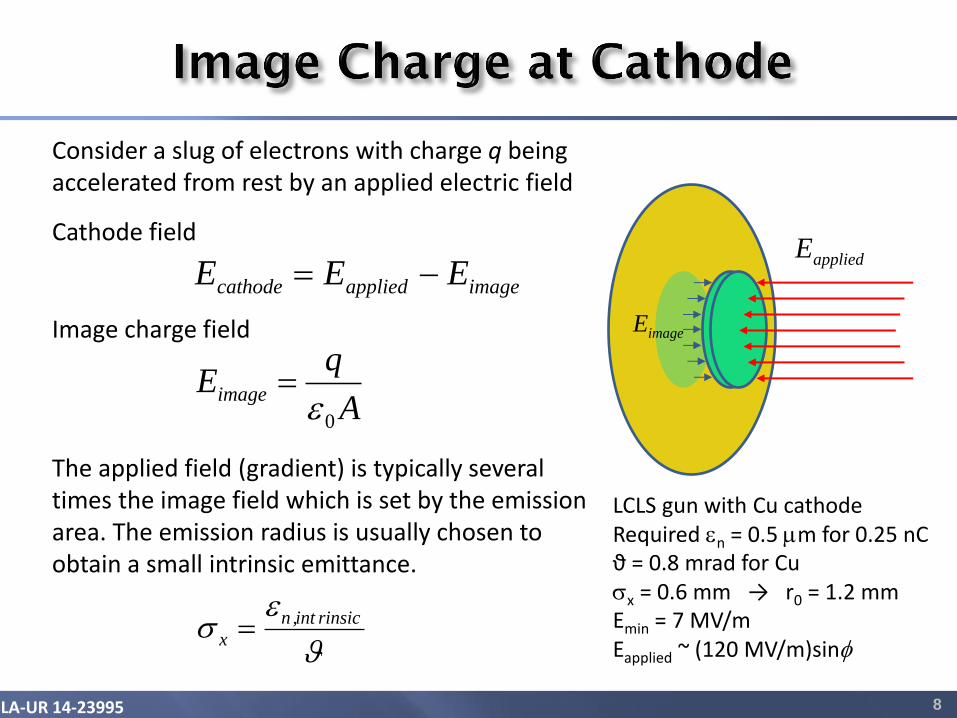
Consider a slug of electrons with charge q being accelerated from rest by an applied electric field
Cathode field
Image charge field
The applied field (gradient) is typically several times the image field which is set by the emission area. The emission radius is usually chosen to obtain a small intrinsic emittance.
imageappliedcathode EEE
LCLS gun with Cu cathode Required n = 0.5 mm for 0.25 nC ϑ = 0.8 mrad for Cu x = 0.6 mm → r0 = 1.2 mm Emin = 7 MV/m Eapplied ~ (120 MV/m)sin
appliedE
imageE
A
qEimage
0
rinsicint,n
x
LA-UR 14-23995
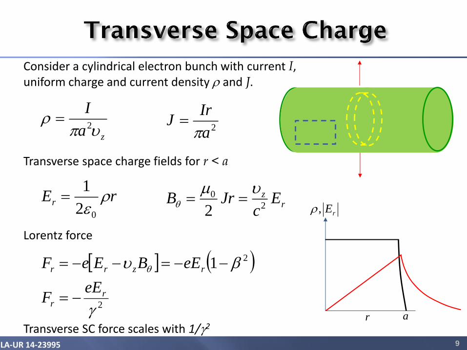
Consider a cylindrical electron bunch with current I, uniform charge and current density r and J.
Transverse space charge fields for r < a
Lorentz force
Transverse SC force scales with 1/g2 9
rE,r
r a
rEr r02
1
rz E
cJrB
2
0
2
m
za
I
r
2
2a
IrJ
2
21
g
rr
rzrr
eEF
eEBEeF

LA-UR 14-23995 10
Longitudinal SC causes the beam to expand along the z direction and reduces its peak current
Longitudinal space charge fields for |z| < L/2
where z is the internal longitudinal coordinate
Due to mixing, the longitudinal (and transverse) SC depends on both z and r.
Longitudinal SC force scales with 1/g
zE,r
z 2/L2/L
zgzgzg
g
rz
22
22)( 222
2
22
0
Lr
LaEz
tz zz

LA-UR 14-23995 11
rE,r
r a
0z
2Lz
Initial bunch with 5 slices Different slices expand radially at different rates
x
x
x
Projected emittance
Slice emittance
Trace-space plots Transverse force is highest at z = 0
The slice emittance, not projected emittance, determines the FEL gain

LA-UR 14-23995 12
x
x
x
Solenoid field
x
x
Projected emittance
Slice emittance
Originally proposed by Carlsten and coined Emittance Compensation, the idea is to use a solenoid magnet to flip the trace-space ellipses and let them move in x-x’ space until the slices are aligned to form smaller projected emittance. Serafini and Rosenzweig later developed the emittance compensation theory based on plasma oscillation of the slices’ envelopes.
1.6-cell RF gun

LA-UR 14-23995 13
DC guns use a large ceramic insulator to stand off the high voltage between a cathode and an anode, creating accelerating gradients of a few MV/m.
Cornell DC gun Gradient = 5 – 10 MV/m Gun exit energy = 0.35 MeV GaAs and K2CsSb photocathodes Bunch repetition rate = 1300 MHz Norm. rms emittance = 0.5/0.3 mm at 80 pC Average current = 65 mA (at 50 pC)

LA-UR 14-23995 14
modelocked laser
klystron
injector
RF signal
harmonic
crystal beam
expander
aperture
lens
solenoid cathode
RF coupling
circulator
electron beam
RF gun was invented by Fraser and Sheffield in the mid-1980s. Pulsed NCRF guns can achieve accelerating gradients > 100 MV/m.

LA-UR 14-23995 15
CAD Model of the LCLS-I Gun
Superfish Model of the LCLS-I Gun
Cathode
Cathode
Frequency = 2,856 MHz Gradient = 120 MV/m Exit energy = 6 MeV Copper photocathode Bunch repetition rate = 120 Hz Norm. rms emittance = 0.4 mm at 250 pC = 0.14 mm at 20 pC
LCLS-I Gun (SLAC/BNL/UCLA)

LA-UR 14-23995 16
PITZ L-band Gun Frequency = 1,300 MHz Gradient = up to 60 MV/m Exit energy = 6.5 MeV Cs2Te photocathode 800 bunches per macropulse Normalized rms emittance 1 nC 0.70 mm 0.1 nC 0.21 mm
Reference: M. Krasilnikov, FEL2013, TUOANO-04 Talk
LA-UR 14-23995 17
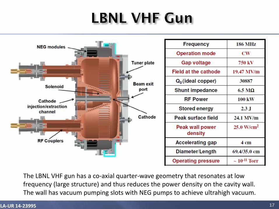
The LBNL VHF gun has a co-axial quarter-wave geometry that resonates at low frequency (large structure) and thus reduces the power density on the cavity wall. The wall has vacuum pumping slots with NEG pumps to achieve ultrahigh vacuum.

LA-UR 14-23995 18
Laser
Cs2Te Photocathode Niobium
Cavity
e-
Rossendorf SRF Gun
Superconducting RF guns offer the benefit of very efficient use of RF power for operations at high bunch repetition but they require a helium cryostat and a liquid helium cryoplant. A 3.5-cell SRF gun has been tested with beams at FZD (Rossendorf).
Courtesy of J. Teichert

LA-UR 14-23995 19
WiFEL (Wisconsin Free-Electron Laser) superconducting quarter-wave gun
Frequency = 199.6 MHz Gradient < 45 MV/m High Tc superconducting solenoid Design beam energy = 4 MeV Pulse repetition rate = 1 kHz up to a few MHz
Quarter-wave cavities have a smaller cross-section compared to full-wave (pill-box) cavities at the same frequency. QW designs of superconducting guns operate at frequencies below 500 MHz so they can be cooled with 4K atmospheric helium.

LA-UR 14-23995 20
50 0 50 100 150 200 250 300 350 400 1
0
1
Field phase [deg]
No
rmal
ized
ele
ctri
c fi
eld
50 0 50 100 150 200 250 300 350 400 1
0
1
Field phase [deg]
No
rmal
ized
ele
ctri
c fi
eld
Launch
= phase at ½ cell exit
D
0
Rate of change in g w.r.t. scaled distance z Rate of change in w.r.t. scaled distance z
zz
g2sinsin
d
d
112
g
g
z
d
d
Scaled distance z
RF wave-number
Dimensionless gradient
kzz
RF
k
2
2
0
2 ckm
eE
e
Typical values for an S-band gun
160105.0
2 mm
k
2
511.02
/120
MeVk
mMeV
LA-UR 14-23995 21
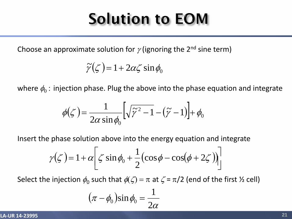
Choose an approximate solution for g (ignoring the 2nd sine term) where 0 : injection phase. Plug the above into the phase equation and integrate
0sin21~ zzg
0
2
0
1~1~
sin2
1gg
z
Select the injection 0 such that z at z = /2 (end of the first ½ cell)
2
1sin 00
Insert the phase solution above into the energy equation and integrate
zzzg 2coscos
2
1sin1 0

LA-UR 14-23995 22
Beam energy at the exit of the LCLS 1½-cell gun is linearly proportional to cavity gradient. The exit energy is almost independent of the launch phase up to a launch phase of 50o. The exit phase increases slowly with injector phase at small phases, but rises quickly if the injection exceeds 30 degrees.

LA-UR 14-23995 23
RF and Magnet Design Codes: These codes model the gun cavities via time and frequency domain solvers, as well as designing the solenoid magnets.
• SUPERFISH-POISSON: free codes from LANL; 2D
• HFSS: commercial code from Ansoft; 3D
• MicroWave Studio: commercial code from CST; 3D
Particle Tracking Codes: These codes integrate the macroparticle trajectories under Lorentz forces, including space charge.
• PARMELA: particle tracking code from LANL; some export restrictions apply
• ASTRA: free parallel code from DESY
• GPT: Commercial code from Pulsar Physics
Particle-in-cell (PIC) Codes: These codes solve the Maxwell-Lorentz equations for particles in a 3D cell consistently. Very time-consuming and complex.
• MicroWave Studio: commercial code from CST
• VORPAL: plasma and PIC simulation code from Tech-X
• MAGIC: 2D and 3D PIC code
LA-UR 14-23995 24
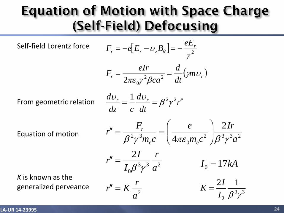
Self-field Lorentz force
rr
rzrr
mdt
d
ca
eIrF
eEBEeF
gg
g
22
0
2
2
From geometric relation rdt
d
cdz
d rr 221g
Equation of motion
2
233
0
2332
0
32
2
2
4
a
rKr
a
r
I
Ir
a
Ir
cm
e
cm
Fr
ee
r
g
gg
kAI 170
33
0
12
gI
IK
K is known as the generalized perveance

LA-UR 14-23995 25
Envelope oscillation in a long solenoid focusing channel
Envelope equation
Equilibrium solution for space-charge dominated beams (ignoring emittance)
Chart Title Chart Title
03
2
2
KkB
cm
eBk
e
Bg2
0
Solenoid wave-number
2
B
eqk
K
eq
z

LA-UR 14-23995 26
01
23
2
2
r
a
K
rcm
prkrr
e
Bgg
g
03
2
2
g
g
KkB
Assuming the particles are largely parallel to the beam axis, ignore second (r2) and higher order terms. Paraxial ray equation for single particles:
rms envelope equation
Acceleration damping
Focusing from an axial solenoid magnetic field
Canonical angular momentum due to magnetic field at cathode
Space charge defocusing
where emittance has both the phase-space and angular momentum parts.

LA-UR 14-23995 27
023
22
g
ˆˆˆkˆ n
f
The slices rotates in x-x’ space about an invariant envelope. The equation of invariant envelope rate of change with respect to z is given by
Definitions
g ˆ2
22
4
3
g
gBf kk
g n
0
3 2
I
IK g
Solutions to invariant envelope equation
Space-charge dominated beams, x > 1
Emittance-dominated beams, x < 1
2
1
3
41
g SCˆ
2
1
3
2
g
g n
emitˆ
2
2
ng
x
Space charge-to-emittance ratio
2
1
03
2
I
ISC
gg
2
1
3
2
g
n
emit
LA-UR 14-23995 28
x
x
x
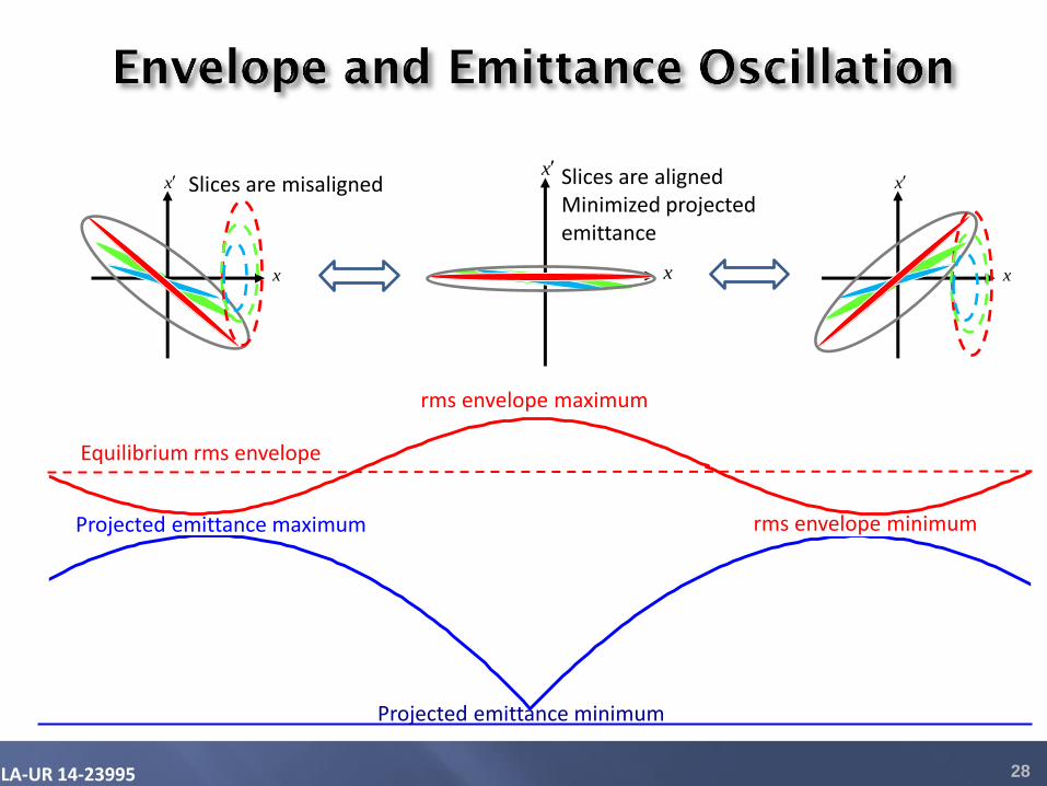
Slices are misaligned
x
x
x
Slices are aligned Minimized projected emittance
x
x
x
-1.5
-1
-0.5
0
0.5
1
1.5
-1.5
-1
-0.5
0
0.5
1
1.5
Chart Title
Equilibrium rms envelope
Projected emittance maximum
Projected emittance minimum
rms envelope maximum
rms envelope minimum

LA-UR 14-23995 29
Gun Solenoid
Emittance oscillations produce two emittance minima after the solenoid. This behavior has been seen in many particle-tracking simulations and experimentally observed at the SPARC photoinjector in Italy. Ferrario et al., PRL 99, 234801 (2007)
Booster Cavity
LA-UR 14-23995 30
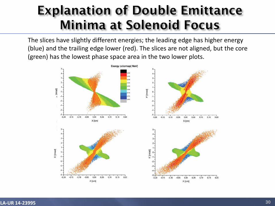
The slices have slightly different energies; the leading edge has higher energy (blue) and the trailing edge lower (red). The slices are not aligned, but the core (green) has the lowest phase space area in the two lower plots.

LA-UR 14-23995 31
Linac entrance
0
1
2
3
4
5
6
0 5 10 15
HBUNCH.OUT
sigma_x_[mm]enx_[um]
sig
ma
_x_
[mm
]
z_[m]
n [
mm
-mra
d]
Z [m]
Plots of normalized emittance (blue) and rms envelope (red) versus z
The beam is matched into the booster at z location where the normalized emittance has a local maximum (between two minima). Subsequent acceleration in the booster damps the emittance oscillation and freezes the second emittance minimum.
Booster starts here
Gun
Courtesy of M. Ferrario
LA-UR 14-23995 32
• The photoinjectors produce electron beams with exceptional brightness (peak current divided by emittance in x and y).
• The slice emittance determines the FEL gain.
• All three gun technologies (DC, NCRF and SCRF) are being considered for high-duty-factor XFEL operation.
• Emittance compensation has been used successfully to achieve very small projected emittance (high brightness).
• The Ferrario technique to match the beams into the booster freezes the final beam emittance at the second minimum.