Rex UHS Conveyor Design Manual Chain · Rex® UHS™ 9608 MatTop® Design Manual (V 1.1) DM-9608-5...
24
Conveyor Design Manual ® ® Rex ® UHS ™ 9608 Series MatTop ® Chain
Transcript of Rex UHS Conveyor Design Manual Chain · Rex® UHS™ 9608 MatTop® Design Manual (V 1.1) DM-9608-5...

Conveyor Design Manual
® ®
Rex® UHS™
9608 Series MatTop® Chain

Rexnord, Rex, TableTop, UHS, TwistLock, Dynamic Transfer System, DTS and MatTop are trademarks of Rexnord Industries, Inc.
All rights reserved.

® ®
Rex® UHS™ 9608 MatTop® Design Manual (V 1.1) DM-9608-1
Table of Contents Introduction / Safety 2-3 Chain Specifications 4-5 Conveyor Construction 6-16
• Squaring the unit • Leveling the unit • Carry & return Way • Head & tail specifications • Sprockets • Conveyor drive • DTS® transfer
Chain Installation 17-21

® ®
Rex® UHS™ 9608 MatTop® Design Manual (V 1.1) DM-9608-2
Introduction Need new introduction…
Contact Rexnord Application Engineering for more information 1.262.376.4800

® ®
Rex® UHS™ 9608 MatTop® Design Manual (V 1.1) DM-9608-3
Safety Considerations PRODUCT SAFETY: Products designed and manufactured by Rexnord are capable of being used in a safe manner; but Rexnord cannot warrant their safety under all circumstances. PURCHASER MUST INSALL AND USE THE PRODUCTS IN SAFE AND LAWFUL MANNER IN COMPLIANCE WITH APPLICABLE HEALTH AND SAFETY REGULATIONS AND LAWS AND GENERAL STANDARDS OF REASONABLE CARE; AND IF PURCHASER FAILS TO DO SO, PURCHASER SHALL INDEMNIFY REXNORD FROM ANY LOSS, COST OR EXPENSE RESULTING DIRECTLY OR INDIRECTLY FROM SUCH FAILURE. SAFETY DEVICES: Products are provided with only safety devices identified herein. IT IS THE RESPONSIBILITY OF PURCHASER TO FURNISH APPROPRIATE GUARDS FOR MACHINERY PARTS in compliance with MSHA or OSHA Standards, as well as any other safety devices desired by Purchaser and/or required by law; and IF PURCHASER FAILS TO DO SO, PURCHASER SHALL INDEMNIFY REXNORD FROM ANY LOSS, COST OR EXPENSE RESULTING DIRECTLY OR INDIRECTLY FROM SUCH FAILURE.

® ®
Rex® UHS™ 9608 MatTop® Design Manual (V 1.1) DM-9608-4
Chain Specifications Pitch: 1.50 in (38.1 mm) Thickness: 0.75 in (19.1 mm) Weight: 2.74 lbs/ft2 (13.3 kg/m2) Chain Strength: 4000 lbs/ft (5900 kg/m) Open Area: 20% Flow Rate: Greater than 26 gallons/minute per ft2 (2800 liters per m2) fully packed
with cans or bottles Link Material: Patent pending polypropylene composite allows for increased load
carrying capacity and reduced stretch at elevated temperatures Pin Material: Proprietary, co-extruded material retains strength and stiffness at
elevated temperatures. Inner core is stiff for superior strength, outer shell provides wear resistance
Widths: 6.00 in (152.4 mm) standard increments, 0.50 in (12.7 mm) possible
increments

® ®
Rex® UHS™ 9608 MatTop® Design Manual (V 1.1) DM-9608-5
Chain Specifications Squaring the Unit Many conveyor chain tracking and drive problems can be attributed to non-square systems. To insure your pasteurizer provides years of reliable service, it is important to verify several parameters prior to installing the chain. To insure the system is square, several measurements be made. In reference to the right and left sides, assume that you are looking into the pasteurizer from the infeed side with the direction of chain travel moving away you. Assuming the end bearings are mounted to the side of the pasteurizer unit and that the measurements are taken from the same location on the bearings:
• Measure the distance from the right side, drive shaft, end bearing to the right side, tail shaft, end bearing. This will be referred as dimension L1.
• Measure the distance from the left side, drive shaft, end bearing to the left side, tail shaft,
end bearing. This will be referred as dimension L2.
• Measure the distance from the right side, drive shaft, end bearing to the left side, tail shaft, end bearing. This will be referred as dimension X1.
• Measure the distance from the left side, drive shaft, end bearing to the right side, tail
shaft, end bearing. This will be referred as dimension X2.
A square pasteurizer
If the conveyor is square, the following will be true:
L1 = L2 X1 = X2

® ®
Rex® UHS™ 9608 MatTop® Design Manual (V 1.1) DM-9608-6
Conveyor Construction If L1 ≠ L2 then adjustments will need to be added in order to correct the dimensions. Adjustments can be made by realigning components or the use of shims. After the adjustments are complete, repeat the measurement of L1, L2, X1 and X2. If X1 ≠ X2 and L1 = L2, it means that the overall pasteurizer has a parallelogram shape and in order for the chain to operate correctly you will need to straighten the conveyor, which in many cases involves straightening the entire pasteurizer. Straightening may involve unbolting the unit from the floor and re-bending the frame in order to align the entire unit. The maximum acceptable limit for deviation between the X1 and X2 dimension for pasteurizers is 0.5 in (12.7 mm). As X1 deviates from X2, the squareness deviates exponentially. Making Sure the Unit is Level: The most critical components to level are the shaft and the slider bed (or wearstrips). The slider bed level should be measured first. If the slider bed is on a slight angle (the height difference between the right and left side is less than 0.50 in), in either one direction or another, it is not necessary to adjust this level because of the difficulty involved. If the slider bed is out of level, the shaft can be adjusted in the same direction to match the slider bed angle. The level of the slider bed is best measured by the use of a transit. A height measurement should be taken by the transit at least every 24.00 in (610.0 mm) across the width of the slider bed (on the top of the wear tracks). The level of the wear track should then be evaluated. Depending on the data gathered, it should be determined whether more data (transit measurements) should be taken. If the measurements of the slider bed indicate considerable variance, the entire slider bed may need to be leveled (see below).
The recommended tolerance for slider bed warp is less than 0.25 in (6.4 mm) over 20.00 ft (6.1 m) wide (or 0.13 in (3.2 mm) over 10.00 ft (3.0 m) wide). If the slider bed surface does not form a continuous plane, it will be necessary to determine the over all shape or degree of warp. In most cases, the overall shape of the warp forms a ”crown” or a “dish.” In this case, it is often easiest to use the average measurement value to establish the base plane.
Leveling the Unit

® ®
Rex® UHS™ 9608 MatTop® Design Manual (V 1.1) DM-9608-7
Conveyor Construction Carry Way Bed The carry way bed is the support structure for the wearstrips. The bed must be constructed so that deflection or deformation does not occur under the load of the supported product. The structure of the carry bed can be of various constructions, including: C-channel, box frame beams or I-beams. The supports should be mounted perpendicular to the travel of the conveyor chain on spacing between 2.00 ft (600.0 mm) to 4.00 ft (1200.0 mm) depending on the size and weight of the product top load. Wearstrips The wearstrips are attached on top of the carry way bed, and serve as the support for the conveyor chain and product load. The wearstrips should be of a material suitable for the chemical and thermal conditions of the pasteurizer.
To provide good contact wear, the layout of the wearstrips should be in either an offset rail or herringbone pattern. The wearstrips should be a minimum of 2.00 in (50.0 mm) width, and spaced on 6.00 in (150.0 mm) centers. The herringbone pattern should be staggered or open throughout the system to allow debris to pass. Rollers may also be used as chain supports. The rollers should have a minimum diameter of 3.00 in (75.0 mm), on 4.00 in (100.0 mm) centers. When using rollers it is important that they remain free spinning and that their center line is perpendicular to the direction of chain travel. Rollers my not be suitable for small products.
Leveling the Wearstrips
® ®
Rex® UHS™ 9608 MatTop® Design Manual (V 1.1) DM-9608-8
Conveyor Construction Chain Guide Clearance Clearance between the conveyor chain, and the pasteurizer frame, wearstrips and support structures must be sufficient so that damage and binding of the conveyor chain does not occur. All thermoplastic materials show considerable dimensional change due to thermal expansion. The unique UHS™ material used in the Rex® 9608 MatTop® chain reduces the amount of thermal expansion; however, consideration for this property is still extremely important. To ensure proper clearance, the increase in chain width due to thermal expansion, and the standard chain clearance must be taken into account. The increase in width due to elevated temperatures is calculated by:
∆L = L x Cte x ∆T
∆T = change in chain operating temperature from ambient. L = chain length or width in inches (in) or (mm) Cte = coefficient of thermal expansion of the chain material For UHS™ material, Cte = 4.0x10⁻⁵ in/in/°F or (2.2 x 10⁻⁵ mm/mm/°C)
Nominal Chain Width Recommended Guide Clearance* 10 ft (3.0 mm) 10 ft -1 in (3.07 m) 15 ft (4.6 mm) 15 ft - 1.5 in (4.61 m) 20 ft (6.1 mm) 20 ft -2 in (6.15 m)
* Calculation based on a warmer unit which is heated to a maximum of 200° F (93 °C) Guide clearance is not guide rail spacing. Guide rails should be positioned to ensure the products are fully supported by the conveyor chain. Chain Return There are two types of chain returns used in pasteurizer construction: internal, and external. Both refer to the location of the return chain in respect to the tanks. Both types of returns will use a series of rollers or half rounds to support the chain as it returns from the drive sprockets to the idle end. The chain supports should have a diameter of at least twice the back-flex radius of the chain. For Rex® UHS™ 9608 MatTop® chain, the minimum back-flex radius is 1.50 in (38.1 mm). The supports should be constructed from a material that will support the weight of the chain and product without deformation. Typically, schedule 40 pipe or equivalent is sufficient, however, it is recommended that the proper strength and bending calculations be applied for the intended loads and conditions. The vertical location of the supports should be positioned so that the top of the support is in line with the bottom of the drive and idle sprockets. The rollers should be parallel to the shafts. The quantity and spacing of the supports depends on the length of the pasteurizer, as well as the amount of excess chain that must be accounted for.

® ®
Rex® UHS™ 9608 MatTop® Design Manual (V 1.1) DM-9608-9
Conveyor Construction
• Internal Returns
When internal returns are used in double-deck pasteurizers, it is important to remember that the amount of chain sag in the upper deck may affect the containers on the lower deck. If the amount of chain sag is not cared for, it can interfere with products on the lower deck.
To address this, Rexnord recommends that the chain sag depth be determined by assuming all of the excess chain created by mechanical and thermal loading fit between the first roller spacing forming the first catenary sag. When the maximum chain depth is known, enough clearance between decks can be designed to ensure the products on the lower deck will not contact the chain from the upper deck. The Application Engineering Specialists at Rexnord’s Industries, Inc. can perform calculations to determine the amount of elongation, chain sag and the correct roller spacing.
• External Returns
The spacing of the return rollers is not as critical when external returns are used. Care should be taken to prevent the excess chain from contacting the floor or any other structures below the pasteurizer.
Head and Tail Shaft Specifications The Rex® Chain Calculation Program performs a shafting analysis for each chain calculation. The program also provides information on available sprocket and bore sizes to aid proper selection. Shafts can be either square with turned down sections for bearings or round with double keyway. Tail shaft(s) should include extension through the bearings so they can be manually rotated. Rex® 9608 Series Sprockets are specifically designed for use in pasteurizers. Both round and square bores are sized to allow free running fit with the shaft to accommodate thermal expansion in the chain.
For best performance, use cold rolled stainless steel shafting with:
Straightness Tolerance = Within 1/32 in (0.8 mm) over the shaft length Twist Tolerance = Maximum of 1/8 Degree/FT (0.4 Degree/M) of shaft length T.I.R. Tolerance = Maximum of 1/32 in (0.8 mm) Surface Finish = 63 µ in (3.2 µ m) Ra
Standard mill quality steel may not meet these requirements. Therefore, some additional straightening and/or machining may be required. Shafting over 10.00 ft (3.0 m) in length and meeting these requirements can be difficult to obtain. For this reason, two shafts can be coupled together to form the required length. In using split shafts, it is important to ensure that the shafts are coupled in time with respect to the sprocket keyway, or the flats of the square. The shafts should be coupled using a rigid coupling. Other couplings may deform or fail causing shaft misalignment.
® ®
Rex® UHS™ 9608 MatTop® Design Manual (V 1.1) DM-9608-10
Conveyor Construction
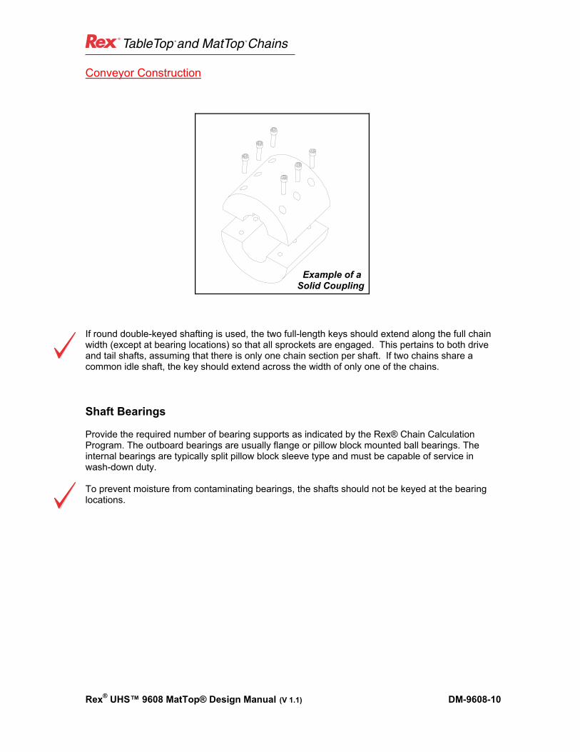
If round double-keyed shafting is used, the two full-length keys should extend along the full chain width (except at bearing locations) so that all sprockets are engaged. This pertains to both drive and tail shafts, assuming that there is only one chain section per shaft. If two chains share a common idle shaft, the key should extend across the width of only one of the chains. Shaft Bearings Provide the required number of bearing supports as indicated by the Rex® Chain Calculation Program. The outboard bearings are usually flange or pillow block mounted ball bearings. The internal bearings are typically split pillow block sleeve type and must be capable of service in wash-down duty. To prevent moisture from contaminating bearings, the shafts should not be keyed at the bearing locations.
Example of a
Solid Coupling
® ®
Rex® UHS™ 9608 MatTop® Design Manual (V 1.1) DM-9608-11
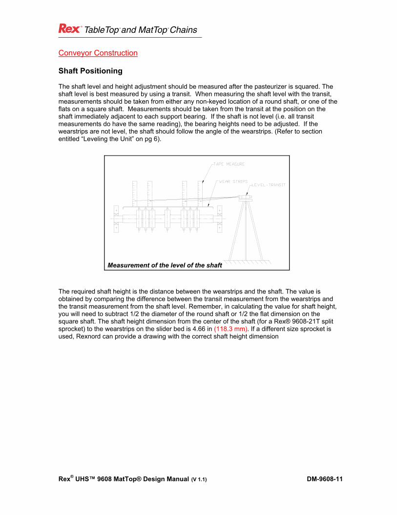
Conveyor Construction Shaft Positioning The shaft level and height adjustment should be measured after the pasteurizer is squared. The shaft level is best measured by using a transit. When measuring the shaft level with the transit, measurements should be taken from either any non-keyed location of a round shaft, or one of the flats on a square shaft. Measurements should be taken from the transit at the position on the shaft immediately adjacent to each support bearing. If the shaft is not level (i.e. all transit measurements do have the same reading), the bearing heights need to be adjusted. If the wearstrips are not level, the shaft should follow the angle of the wearstrips. (Refer to section entitled “Leveling the Unit” on pg 6).
The required shaft height is the distance between the wearstrips and the shaft. The value is obtained by comparing the difference between the transit measurement from the wearstrips and the transit measurement from the shaft level. Remember, in calculating the value for shaft height, you will need to subtract 1/2 the diameter of the round shaft or 1/2 the flat dimension on the square shaft. The shaft height dimension from the center of the shaft (for a Rex® 9608-21T split sprocket) to the wearstrips on the slider bed is 4.66 in (118.3 mm). If a different size sprocket is used, Rexnord can provide a drawing with the correct shaft height dimension
Measurement of the level of the shaft
® ®
Rex® UHS™ 9608 MatTop® Design Manual (V 1.1) DM-9608-12
Conveyor Construction
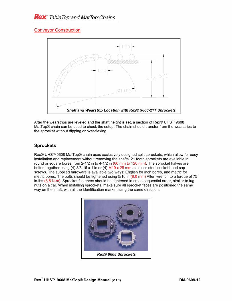
After the wearstrips are leveled and the shaft height is set, a section of Rex® UHS™9608 MatTop® chain can be used to check the setup. The chain should transfer from the wearstrips to the sprocket without dipping or over-flexing. Sprockets Rex® UHS™9608 MatTop® chain uses exclusively designed split sprockets, which allow for easy installation and replacement without removing the shafts. 21 tooth sprockets are available in round or square bores from 2-1/2 in to 4-1/2 in (60 mm to 120 mm). The sprocket halves are bolted together using (4) 3/8-16 x 1 in or (4) M10 x 25 mm stainless steel socket head cap screws. The supplied hardware is available two ways: English for inch bores, and metric for metric bores. The bolts should be tightened using 5/16 in (8.0 mm) Allen wrench to a torque of 75 in-lbs (8.5 N-m). Sprocket fasteners should be tightened in cross-sequential order, similar to lug nuts on a car. When installing sprockets, make sure all sprocket faces are positioned the same way on the shaft, with all the identification marks facing the same direction.
Rex® 9608 Sprockets
Shaft and Wearstrip Location with Rex® 9608-21T Sprockets

® ®
Rex® UHS™ 9608 MatTop® Design Manual (V 1.1) DM-9608-13
Conveyor Construction In pasteurizer applications, the maximum number of sprockets should be used. The sprockets fit into pockets located every 3.00 in (76.2 mm) across the chain width at a maximum of 4 sprockets per foot of width. With a typical pasteurizer, it is important to remember that the loading is high due to the length and load of the system. Because of the high load, the chain can have a tendency to deflect between the sprockets. The smaller space between sprockets, the less bending of the chain between sprockets. If the chain deflects between the sprockets, the discharge transfer can be compromised. If center support bearings are required, it will be necessary to skip some of the possible sprocket locations. It is acceptable to allow approximately for 9.00 in (229.0 mm) of space between sprockets, skipping 3 sprockets. It is preferable, however, to minimize the distance allowed for the bearings so that maximum chain support can be obtained. As stated above, this will reduce chain bending between sprockets, and allow for better transfers at the infeed and discharge. After the sprockets are installed, and the shaft height is set, a section of the chain can be used to check the setup. The chain should transfer from the wearstrips to the sprocket without dipping or over-flexing. Fixing the Sprockets on the Shaft Once the sprockets are assembled on the shaft, the sprockets need to be positioned on the shaft. A section of chain (6 pitches or more) can be used as a template to position the sprockets on the shaft. The sprockets are designed so that they “float” axially on the shaft so that when the chain expands in width due to temperature increase, the sprockets adjust in position on the shaft to accommodate that change in temperature. The center-most sprockets need to be fixed in position so that the chain tracks correctly and locates itself in the center of the pasteurizer width. It is recommended that between 2 to 4 sprockets be fixed in position from axial movement (in the shaft length direction). The method of fixing the sprocket position need not be complicated. The only requirement is that a semi-permanent mechanical limit or obstruction be attached to the shaft, which will prevent the center group of sprockets from moving axially along the shaft. The mechanical limit can be a shaft collar, a set screw threaded into the shaft or simply a piece of keystock welded to the shaft. This mechanical limit should be attached to the shaft at the outermost surfaces of the group of fixed sprockets and fix the sprockets at such a location that the chain is centered widthwise in the pasteurizer.
Fix center most sprockets to provide tracking

® ®
Rex® UHS™ 9608 MatTop® Design Manual (V 1.1) DM-9608-14
Conveyor Construction Conveyor Drive With the increasing width of pasteurizers, the required size of the drive shaft may be difficult to obtain with the given specifications. A solution to this is to use two drive motors (and gearboxes), one on each side of the chain, to reduce the shaft load. When using this drive method, it is extremely important to keep the drives synchronized to avoid undo stress on the chain or other mechanical devices. Another option to the two-drive system is to use two smaller independent chains to make up the pasteurizer width. This system would use two shafts (either coupled or one piece) on the drive end and independent drives. The tail shaft can be either independent or common. If a common tail shaft is used, it should be keyed to only one of the chains. With this common arrangement, drive synchronization is not important. Please contact the Application Engineering Specialists at Rexnord’s Industries, Inc. to determine the proper drive and shafting requirements. Setting up the Rex® Dynamic Transfer System™ (DTS®) Transfer The most important item to remember when designing a Rex® DTS® transfer is to provide for adjustability. There should be an adjustment at least every 2.00 ft (600.0 mm) which allows for the DTS® transfer conveyor to be moved in and out, as well as up and down, from the 9608 chain wrap. The reason for the adjustments to be spaced at such close proximity is that the transfer is one of the most critical setup points in the system. The overall tolerance as described in the conveyor leveling section requires that the 9608 chain and shafts be level within 0.25 in (6.4 mm) over a 20.00 ft (6.1 m) width. The DTS® transfer cannot tolerate this variance in height. In order to design and implement a successful DTS® transfer, the transfer conveyor needs to be designed so that it is flexible and adjustable enough to accommodate any warp or variance in the conveyor. Recommendations for positioning of the DTS® chain relative to the chain wrap of the 9608 MatTop® chain are detailed in the drawing below (see drawings on next page). These positions are recommended starting points for setup. It is quite possible that the position may need to be adjusted slightly depending on the product that is being conveyed (i.e. can or bottle size) and the infeed/discharge speed. Another consideration for setup is the position of the wearstrips for the DTS® chain. It is recommended that the wearstrips be positioned to prevent the DTS® chain from “tipping” when transferring product from the DTS® chain to and from the pasteurizer. In order to accomplish this, wearstrips should be located as close as possible to the outer most extremities of the chain. Specifically, one wearstrip should be located at the plug end side of the DTS® chain and that wearstrip should be wide enough to provide common support between the DTS® chain and any adjacent chain which product will be transferred on. A second wearstrip should be located as close as possible to the DTS® chain transfer tip. This will help prevent the chain from tipping if the conveyed product is not fully packed on the conveyors. It is also possible to set up the DTS® such that the DTS® tip is resting on the 9608 MatTop® chain wrap. The DTS® tip resting on the 9608 MatTop® chain wrap is preferable and will further prevent the possibility of the DTS® chain tipping. Some possible wearstrip positions are listed below.

® ®
Rex® UHS™ 9608 MatTop® Design Manual (V 1.1) DM-9608-15
Conveyor Construction
Infeed Rex® DTS® setup, off Rex® 7705 DTS® - R PT 7.50 on to Rex® 9608-21T
Discharge Rex® DTS® setup, Rex® 9608-21T onto Rex® 7705 DTS® -R PT 7.50
For discharge conveyors it is recommended to only use 7705 DTS® - R PT chain For discharge use only To allow extra room for the DTS® -R conveyor structure Rexnord recommends the 7-1/2 inch.
The 4-1/2 inch can bee used. Contact Application Engineering for Dimensions
For infeed conveyors both 7705 DTS® PT and 7705 DTS® - R PT can be used following the above dimensions

® ®
Rex® UHS™ 9608 MatTop® Design Manual (V 1.1) DM-9608-16
Conveyor Construction
Rex® DTS® in Action
The Rex® Positrack™ feature can be used to adjust the position of the DTS® chain relative to the 9608 chain wrap. On the infeed side, remember that the product pressure will force the DTS® chain toward the 9608 chain wrap. A wearstrip should be located between the Positrack™ and the DTS® tip to prevent motion in this direction. On the outfeed or discharge side, the product pressure will force the DTS® chain to move in a direction away from the 9608 chain wrap. A wearstrip should be located between the Positrack™ feature and the plug end of the chain to prevent movement in this direction. This same design and setup strategy applies when using the Rex® 815 TableTop® Transfer chain for the infeed and discharge transfer conveyors.

® ®
Rex® UHS™ 9608 MatTop® Design Manual (V 1.1) DM-9608-17
Chain Installation Installation of the Rex® UHS™ 9608 MatTop® Chain
To avoid personal injury, all machinery must be turned off and locked out, prior to chain installation, inspection, maintenance and removal.
Always use safety glasses to protect your eyes. Wear protective clothing, gloves
and safety shoes.
Support the chain to prevent uncontrolled movement of the chain and parts.
Maintain tools in proper condition and assure their proper use.
Do not attempt to connect or disconnect chain unless chain construction is clearly known and understood.
Do not use any section of damaged chains because they may have been
overloaded and yielded.
Follow the guidelines set forth by your company when using potentially dangerous equipment.
The Rex® UHS™9608 MatTop® chain should not be installed into the pasteurizer until all slider bed and shaft height adjustments are made. At this time the slider bed should be checked for obstructions or other objects that may cause damage to the chain. There are several methods in which the chain can be installed into the pasteurizer depending on the layout. Two methods of loading the chain in the pasteurizer will be described below; however, how the chain is installed into the conveyor is not as important as how the slack of the chain is taken out of the pasteurizer. The Rex® 9608 MatTop® chain is completely bi-directional, and can be installed in either direction without loss of strength.
!CAUTION

® ®
Rex® UHS™ 9608 MatTop® Design Manual (V 1.1) DM-9608-18
Chain Installation The chain can be installed into the system by physically loading sections of chain into the pasteurizer from side access doors. The chain is shipped in crates in 3.00 ft (914.0 mm) long sections and assembled to the width that was ordered. The sections can then be pinned together using the Rex® MatTop® Rods provided by Rexnord. It is important to remember to close the Twist Lock® to secure the pin in the chain. This method is time consuming and requires that a lot of extra chain, which will need to be taken out of the system before final operation of the pasteurizer.
Rex® TwistLock®
A Standard Flathead Screwdriver
The chain can be installed from one side of the conveyor. In this method, the transfer conveyor at either the infeed or discharge side of the pasteurizer needs to be moved out of the way. Cables (at least 2 per 10.00 ft (3.0 m) width of chain, 1/2 in diameter minimum) should be installed over the return rollers of the pasteurizer and tensioned. These cables will provide a temporary wear track for the chain to slide on to install the chain in the return side. A heavy rope, cable or nylon strap* should then be installed the length of the pasteurizer. This rope will be used to pull the chain into the system from the opposite side where the chain is being installed.
Be sure to calculate in advance the tensile requirements for the rope, cable, nylon strap etc. This component requires a tensile strength high enough to pull the entire weight of the 9608 chain (2.74 lbs/ft²) with a factor of safety. Improper planning could cause serious injury to setup personnel.
The first pitch of the chain being installed needs to be modified and fit with a steel 5/16 in pin. One link module approximately in the center of chain as well as a link module at each quarter across the width of the 9608 chain should be removed (see below). These spaces provide an area for a harness to be attached to the chain to allow for the chain to be attached to the rope, cable or nylon strap and be pulled through the system.
!CAUTION

® ®
Rex® UHS™ 9608 MatTop® Design Manual (V 1.1) DM-9608-19
Chain Installation
The chain should be assembled on the side of the pasteurizer where the transfer conveyor was moved. As sections of chain are assembled, from the opposite side, the chain can be pulled forward by pulling on the rope, cable or nylon strap with the use of a winch, mechanical drive or vehicle. Chain should be installed in both the carry side and the return section in this manner. After the chain is installed in the carry and return sections, the carry section and the return sections can then be pinned together over the sprockets at either the drive or tail shafts. Before the chain is wrapped over the sprockets, verify once again that the sprocket pockets line up with the sprockets on the shaft. Once the chain is completely pinned together, the excess chain can be taken out of the pasteurizer. Only excess chain is to be taken out of the pasteurizer, the chain should NOT be preloaded. Excess chain should only be removed when the pasteurizer is at room temperature. Preloading the chain can cause injury to operators as well as bend structural members or the shaft of the pasteurizer. The excess chain can be taken out by one of two methods. In either of the two methods, it is required that a pin be taken out in the carry side of the chain. If a pin is removed near the tail shaft, it may be necessary to temporarily secure the tail shaft from rotating, causing the chain to fall into the return section. Before removing the excess links, it will then be necessary to dismantle the tail shaft secure or locking method. The first method of removing excess chain from the pasteurizer is by using the Rex® UHS™9608 chain assembly tools. The chain assembly tools can be purchased in 1.00 ft (305.0 mm) or 3.00 ft (914.0 mm) width increments. The assembly tools are to be inserted in the chain as seen below. There should be a maximum of 9.00 in (229.0 mm) between assembly tools.
Rex® Chain Assembly Tool

® ®
Rex® UHS™ 9608 MatTop® Design Manual (V 1.1) DM-9608-20
Chain Installation Assembly Tool Instructions To aid the final assembly, and excess chain removal, a special chain assembly tool may be used. The tools are available in 1.00 ft (305.0 mm) or 3.00 ft (914.0 mm) width increments and should be spaced equally across with width of the chain. Generally, 3.00 ft (914.0 mm) of assembly tool is required for every 4.00 in (102.0 mm) of chain width.
Rex® Assembly Tool
Place the halves of the assembly tool on the chain with the pins inserted into the gaps of the chain and the puller blocks facing each other. The puller blocks must be lined up with each other precisely so that the threaded rod does not bend when inserted. The pins must all be pulling on the flat vertical portion of the links, not the round sides of the links. One of the puller blocks will have a vertical slot and the other will have a thrust bearing. When using multiple assemblies across the chain width, make sure they are lined up in the same direction and the same distance apart. The puller blocks should be far enough apart to allow for the proper amount of chain to be removed. The maximum distance apart is 27.00 in (650.0 mm).
The threaded rod has a nut welded on one end. Slide the rod through the bearing side of the puller so the welded nut and a washer are aligned against the thrust washer. From the opposite side, align a nut into the vertical slot of the puller block.
To apply tension to the chain, tighten the weld nut. When enough tension is applied to the chain, the pin may be removed from the chain. Remove rows of chain and continue to tighten the weld nut to bring the chain together. It may be necessary to reposition the chain assembly tools if there is more excess chain than the length of the assembly tool threaded rod. If the assembly tools need to be repositioned, reposition one at a time so that the chain does not creep back.
When all the excess chain is removed, advance the chain assembly tools forward until the chain is in position to accept the connecting pin. Install the pin, close the TwistLock® plug gate, and remove the chain assembly tools.
® ®
Rex® UHS™ 9608 MatTop® Design Manual (V 1.1) DM-9608-21
Chain Installation A second method for removing excess chain is to use the chain drive. In this method, clamp the chain to the slider bed with c-clamps on each side of the chain (in line) near the drive shaft of the pasteurizer. Be sure to place a section of wood (a 2 x 4 or equivalent) or metal angle iron between the chain and the clamp so the plastic does not fracture. Back drive the gearbox by either reversing the drive or using a drill motor to run the drive in reverse. Initially, only back drive the chain enough to take off the chain tension. When the chain tension is released, remove a pin and some excess pitches. Continue to back drive and remove pitches until all the excess chain is removed from the pasteurizer. After removing the excess chain in the system it is recommended to “dry-run” the system for 3 to 4 cycles to allow the mechanical drive to pull all components in full contact. At this point, it is recommended to review the excess chain in the return and make any final adjustments to the amount of excess chain. Once the dry-run is complete, the pasteurizer can be filled and brought up to temperature. Observation of the chain for several cycles is recommended. If all systems are correct, the pasteurizer is ready to be loaded.

WORLDWIDE CUSTOMER SERVICE
8rx9608dm-en © Copyright 2005 Rexnord Industries, Inc. 4/05
AUSTRALIA Rexnord Australia Pty. Ltd.Picton, New South WalesPhone: 61.2.4677.3811Fax: 61.2.4677.3812
BRAZIL Rexnord Correntes Ltda.Sao Leopoldo - RSPhone: 55.51.579.8022Fax: 55.51.579.8029
CANADARexnord Canada Ltd.Scarborough, OntarioPhone: 1.416.297.6868Fax: 1.416.297.6873
CHINARexnord ChinaShanghai, ChinaPhone: 86.21.62701942Fax: 86.21.62701943
EUROPERexnord NV/SAMechelen, BelgiumPhone: 32.70.22.33.66Fax: 32.70.22.33.67
Rexnord Marbett, S.r.L.Correggio (RE), ItalyPhone: 39.0522.639333Fax: 39.0522.637778
Rexnord FlatTop Europe b.v.s-Gravenzande, NetherlandsPhone: 31.174.445111Fax: 31.174.445222
LATIN AMERICARexnord International, Inc.Milwaukee, WisconsinPhone: 1.414.643.3000Fax: 1.414.643.3222
MEXICORexnord S.A. de C.V.Queretaro, Qro.Phone: 52.442.218.5000Fax: 52.442.218.1090
SINGAPORERexnord International, Inc.Singapore City, SingaporePhone: 65.6338.5622Fax: 65.6338.5422
UNITED STATESEastern Service CenterAtlanta, GeorgiaPhone: 1.770.431.7200Fax: 1.770.431.7299
Central Service CenterGrove City, OhioPhone: 1.614.675.1800Fax: 1.614.675.1898
Southern Service CenterArlington, TexasPhone: 1.817.385.2800 Fax: 1.817.385.2873
World Class Customer Service
For over 100 years the dedicated people of Rexnord have delivered
excellence in quality and service to our customers around the globe.
Rexnord is a trusted name when it comes to providing skillfully engi-
neered products that improve productivity and efficiency for industrial
applications worldwide. We are committed to exceeding customer
expectations in every area of our business: product design, applica-
tion engineering, operations and customer service.
Because of our customer focus, we are able to more thoroughly
understand the needs of your business and have the resources avail-
able to work closely with you to reduce maintenance costs, eliminate
redundant inventories and prevent equipment down time.
Rexnord represents the most comprehensive portfolio of power trans-
mission and conveying components in the world with the brands you
know and trust.
ThePower ofRexnord™
www.rexnord.com
FLATTOP BEARINGS GEAREDPRODUCTS
INDUSTRIALCHAIN
COUPLINGS AEROSPACE SPECIALCOMPONENTS