REVUE THOMMEN AG - AWI
105
Transcript of REVUE THOMMEN AG - AWI


REVUE THOMMEN AG CH-4437 Waldenburg
AC32 DIGITAL AIR DATA COMPUTER INSTALLATION MANUAL
Page 2 of 105
04-Jan-2011 Document No. AC-INST-500 Revision 2.1
REVISION HISTORY
REVISION DESCRIPTION ISSUE DATE INITIAL CHECKED
1.0 INITIAL RELEASE 30th Aug, 2004 AG RW
1.1 Appendix VI - Equipment Dimensions : Compact Case added.
Appendix VII - Identification Plates added.
Note 1 added in Section I –1-A
In Section III-1-C
Lightning Induced Transient Susceptibility- RTCA/DO-160D Section 22.0 Cat. [A3E3] changed to RTCA/DO-160D Section 22.0 Cat. [A3J33]
18th Jan, 2005 AG RW
1.2 Appendix - Software Version SW 2.10 features added
23rd Nov, 2005 AG RW
1.3 NOTE 2 added in Sec IV-1-E2 9th Dec, 2005 AG RW
1.4 Appendix - Software Version SW 2.11 features added
Section III-1-C Environmental Qualification updated
23rd May, 2006 AG RW
1.5 Appendix X - Software Version SW 2.31 feature added
Appendix XI – Outputs added
Mating Electrical Connector MS Number introduced on page 40
Total Air Temperature (TAT) Calibration Table: Resistance Pt 100 added in Appendix V
17th Jan, 2008 AF RW
1.6 Appendix VII – Env. Cat. in Identification Plate added
Appendix XII – SW Version 2.40 feature added
Appendix XIII – SW Version 2.50/2.51 features added
Document Formats changed
12th Mar, 2008 RW MB
1.7 Appendix XIII – SW Version 2.51 label 242 resolution corrected
23-May-2008 RW MB
1.8 Appendix XIV – SW Version 2.60 features added
20-April-2009 AF RW
1.9 formal changes throughout the document
TAT probe interface updated
Discrete I/O functions updated
Appendix I Failure Codes, Failure
14-Oct-2009 AF RW

REVUE THOMMEN AG CH-4437 Waldenburg
AC32 DIGITAL AIR DATA COMPUTER INSTALLATION MANUAL
Page 3 of 105
04-Jan-2011 Document No. AC-INST-500 Revision 2.1
REVISION DESCRIPTION ISSUE DATE INITIAL CHECKED
class and BIT Matrix added
Appendix III Airspeed calibration table extended
Appendix IV Mach no. calibration table extended
Appendix V TAT/OAT calibration table updated
Appendix XI „IAS damping‟ and „Calculation of impact pressure qci‟ added
Appendix XV – SW Version 2.70 features added
2.0 Change of logical state of Bit 13 label 270 for selected SW versions
27-May-2010 MB RW
2.1 G.2: ARINC 429 transmit channel bus load specified. Appendix XVI – HW version 2.21 / MOD 01A change for improved ARINC 429 bus load.
04-Jan-2011 RW AF
CAUTION: Before attempting any installation activities on the equipment covered in this manual, verify that you have complete and up-to-date publications by referring to the applicable manual revisions and service bulletin indices.

REVUE THOMMEN AG CH-4437 Waldenburg
AC32 DIGITAL AIR DATA COMPUTER INSTALLATION MANUAL
Page 4 of 105
04-Jan-2011 Document No. AC-INST-500 Revision 2.1
SERVICE BULLETIN INDICES
SB No. SERVICE BULLETIN
SUBJECT EDITION / REVISION
NUMBER Date
AD32/AC32/01 Hardware and Software
Modification Initial Release 30th August, 2004
AC32/04 Hardware Modification Initial Release 02-Dec-2010

REVUE THOMMEN AG CH-4437 Waldenburg
AC32 DIGITAL AIR DATA COMPUTER INSTALLATION MANUAL
Page 5 of 105
04-Jan-2011 Document No. AC-INST-500 Revision 2.1
Table of Contents Page
REVISION HISTORY.......................................................................................................................................... 2
SERVICE BULLETIN INDICES .......................................................................................................................... 4
SECTION I .......................................................................................................................................................... 9
Introduction ................................................................................................................................. 9 A. Purpose of the manual ........................................................................................................ 9 B. Equipment Specification ...................................................................................................... 9 C. Technical Specification ...................................................................................................... 13 D. Equipment Dimensions ..................................................................................................... 14 E. Interface Block diagram ..................................................................................................... 16
SECTION II ....................................................................................................................................................... 17
General Information................................................................................................................... 17
Description ................................................................................................................................ 17 A. Equipment Description ...................................................................................................... 17
Operations ................................................................................................................................ 18 A. Theory of Operations ......................................................................................................... 18 B. Operating Modes ............................................................................................................... 22
Testing ...................................................................................................................................... 23 A. Built-in-Test ....................................................................................................................... 23 B. Failure Modes.................................................................................................................... 24
SECTION III ...................................................................................................................................................... 26
Approvals .................................................................................................................................. 26 A. General ............................................................................................................................. 26 B. Instructions for Continued Airworthiness............................................................................ 26 C. Environmental Qualification ............................................................................................... 27
SECTION IV ..................................................................................................................................................... 31
Installation ................................................................................................................................. 31 A. General ............................................................................................................................. 31 B. Unpacking and Inspecting ................................................................................................. 31 C. Pre and Post Installation Check ........................................................................................ 31 D. Electrical Interface ............................................................................................................. 31 E. Electrical connector ........................................................................................................... 35 G. Digital Data Interfaces ....................................................................................................... 43 G.3.1 Label 203 (Pressure Altitude) ....................................................................................... 46 G.3.12 Label 217 (Indicated static pressure) .......................................................................... 57 G.3.20 Label 320 (Magnetic Heading) ................................................................................... 65 I. ICAO Encoded Altitude Output ........................................................................................... 71 J. RS-232 Serial Interface ...................................................................................................... 71

REVUE THOMMEN AG CH-4437 Waldenburg
AC32 DIGITAL AIR DATA COMPUTER INSTALLATION MANUAL
Page 6 of 105
04-Jan-2011 Document No. AC-INST-500 Revision 2.1
SECTION V ...................................................................................................................................................... 72
1. Trouble shooting ................................................................................................................... 72
2. Maintenance .......................................................................................................................... 73
A. Recalibration Interval ............................................................................................................ 73
APPENDICES ................................................................................................................................................... 74
Appendix I ................................................................................................................................. 74 Failure Codes ........................................................................................................................ 74
Appendix II ................................................................................................................................ 78 Altimeter Calibration Table ..................................................................................................... 78
Appendix III ............................................................................................................................... 79 Airspeed Calibration Table ..................................................................................................... 79
Appendix IV ............................................................................................................................... 80 MACH Number Calibration Table ........................................................................................... 80
Appendix V ................................................................................................................................ 82 Total Air Temperature (TAT) / Outside Air Temperature (OAT) Calibration Table .................. 82
Appendix VI ............................................................................................................................... 83 Equipment Dimensions : Compact Case ................................................................................ 83
Appendix VII .............................................................................................................................. 85 Identification Plates ................................................................................................................ 85
Appendix VIII ............................................................................................................................. 86 Software Version SW 2.10: .................................................................................................... 86
Appendix IX ............................................................................................................................... 90 Software Version SW 2.11: .................................................................................................... 90
Appendix X ................................................................................................................................ 91 Software Version SW 2.41: .................................................................................................... 91
Appendix XI ............................................................................................................................... 92 Software Version 2.30:........................................................................................................... 92
Appendix XII .............................................................................................................................. 94 Software Version SW 2.40: .................................................................................................... 94
Appendix XIII ............................................................................................................................. 95 Software Version SW 2.50: .................................................................................................... 95 Software Version SW 2.51: .................................................................................................... 96
Appendix XIV ............................................................................................................................ 97 Software Version SW 2.60: .................................................................................................... 97
Appendix XV ............................................................................................................................. 99 Software Version SW 2.70: .................................................................................................... 99

REVUE THOMMEN AG CH-4437 Waldenburg
AC32 DIGITAL AIR DATA COMPUTER INSTALLATION MANUAL
Page 7 of 105
04-Jan-2011 Document No. AC-INST-500 Revision 2.1
Multiple configurable VMO ...................................................................................................... 104
Appendix XVI .......................................................................................................................... 105 Hardware Version 2.21 / MOD 01A: ..................................................................................... 105
List of Figures Page Figure 1: Equipment Front and Rear View ........................................................................................ 14 Figure 2: Equipment Side and Top View ........................................................................................... 15 Figure 3: AC32 Block Diagram .......................................................................................................... 16 Figure 4: Primary Power Fail............................................................................................................. 25 Figure 5: AC32 Harness Shielding .................................................................................................... 33 Figure 6: AC32 Primary Power Fail ................................................................................................... 34 Figure 7: Wiring Diagram .................................................................................................................. 39 Figure 8: Digital Air Data Computer Communication ......................................................................... 40
List of Tables Page Table 1: Type Identification ............................................................................................................... 11 Table 2: Installation Kit ...................................................................................................................... 12 Table 3: Technical Specification ....................................................................................................... 13 Table 4: ARINC429 Labels ............................................................................................................... 20 Table 5: Operating ranges, limiting values and tolerances ................................................................ 21 Table 6: Fault code handling ............................................................................................................. 24 Table 7: Environmental Qualification ................................................................................................. 29 Table 8: Pin Assignments ................................................................................................................. 37 Table 9: Resistance Pt 500 ............................................................................................................... 41 Table 10: TAT Signals ...................................................................................................................... 41 Table 11: ARINC 429 Labels ............................................................................................................ 43 Table 12: ARINC 429 I/O Transfer labels .......................................................................................... 45 Table 13: ARINC 429 I/O Transfer for Baro Correction ..................................................................... 45 Table 14: ARINC 429 Labels Format ................................................................................................ 45 Table 14: Discrete Inputs .................................................................................................................. 70 Table 15: Discrete Outputs ............................................................................................................... 71 Table 16: Trouble Shooting Procedures ............................................................................................ 72

REVUE THOMMEN AG CH-4437 Waldenburg
AC32 DIGITAL AIR DATA COMPUTER INSTALLATION MANUAL
Page 8 of 105
04-Jan-2011 Document No. AC-INST-500 Revision 2.1
List of Abbreviations and Acronyms
Abbreviation Description
A/C Aircraft
Abs Absolute
ADC Air Data Computer
ARINC Aeronautical Radio Inc.
ASCII American Standard Code for Information Interchange
BIT Built In Test
DC Direct Current
Diff Differential
EMI Electro Magnetic Interference
FAA Federal Aviation Administration (USA)
FAR Federal Aviation Regulation
FI Flight Instruments
FIG Figure
HW Hardware
ICAO International Civil Aviation Organization
IF Interface
N.A. Not applicable
NC Not Connected
REV Revision
RTCA Radio Technical Commission for Aeronautics
RTW REVUE THOMMEN AG, Waldenburg
RVSM Reduced Vertical Separation Minima
SSEC Static Source Error Correction
SW Software
TBD To Be Defined
TSO Technical Standard Order
HIRF High Intensity Radiated Field

REVUE THOMMEN AG CH-4437 Waldenburg
AC32 DIGITAL AIR DATA COMPUTER INSTALLATION MANUAL
Page 9 of 105
04-Jan-2011 Document No. AC-INST-500 Revision 2.1
SECTION I
Introduction
A. Purpose of the manual
This manual provides the specifications, installation instructions and system maintenance in details for the REVUE THOMMEN AC32 Digital Air Data Computer equipment. This manual also defines interface design requirements including mechanical and electrical characteristics for REVUE THOMMEN AC32. The Interface Control Document (ICD) information is also covered in detail in this manual. The description and procedures are covered in different topics as shown in the Table of Contents, and the troubleshooting procedures are given under sections to identify the fault and failure conditions of the equipment with the interface systems. The contents of this manual have been verified by actual performance of the equipment prior to distribution of printed copies. The procedures in this manual are to be performed by qualified personnel familiar with REVUE THOMMEN AC32 Digital Air Data Computer Equipment. Note 1 : This manual replaces the AC32 Interface Control Document (Doc no. AD-ICD-530).
B. Equipment Specification
B.1 Applicable Documents
The following column shows the list of relevant applicable documents which forms the basis of approvals of the AC32 Digital Air Data Computer. STANDARDS
TSO-C106 Air Data Computer
SAE AS8002 Air Data Computer Minimum Performance Standards
ARINC 706-4 Mark 5 Subsonic Air Data System
ARINC 607-3 Design Guidance for Avionic Equipment
ARINC 429 Mark 33 Digital Information Transfer System (DITS)
TSO-C88a Automatic Pressure Altitude Reporting Code Generating Equipment
SAE AS8003 Minimum Performance Standard for Automatic Pressure Altitude Reporting Code Generating Equipment
MILITARY
MS33649 Bosses, Fluid Connection - Internal Straight Thread
MIL-C-14806 Coating, reflection reducing, for instrument cover glasses and lighting wedges

REVUE THOMMEN AG CH-4437 Waldenburg
AC32 DIGITAL AIR DATA COMPUTER INSTALLATION MANUAL
Page 10 of 105
04-Jan-2011 Document No. AC-INST-500 Revision 2.1
SPECIFICATIONS
AC-SPE-500 AC32 Specification Digital Air Data Computer
ADAC-SWR-420 ADAC Software Requirements
Limitations Limited to manufacturer specifications of the digital input bus and to the applicable configuration and Mod status.
COMMERCIAL
RTCA/DO-160D Environmental Conditions and Test Procedures for Airborne Equipment with Change, 1 Change 2 and Change 3
ED-12B Software Considerations in Airborne Systems and Equipment Certification RTCA/DO-178B
ED-14D Environmental Conditions and Test Procedures for Airborne Equipment RTCA/DO-160D
ED-80 ED-80 / RTCA/DO-254 Design Assurance Guidance for Airborne Electronic
RTCA/DO-254 Hardware
OTHER PUBLICATIONS
- None

REVUE THOMMEN AG CH-4437 Waldenburg
AC32 DIGITAL AIR DATA COMPUTER INSTALLATION MANUAL
Page 11 of 105
04-Jan-2011 Document No. AC-INST-500 Revision 2.1
B.2 Identification
B.2.1 Type Identification
Type : AC32.10.21.11.AE (For Sample)
AC32 Digital Air Data Computer
. 1 - 1000…53000 ft / 0/20…200 Knots
.-0 Standard Function
.2 Power Supply 28 VDC (< 7 W)
.-1 ARINC 429 serial data bus
(High speed mode)
.1 With TAT probe input
500 Ohm acc. to ARINC 706-4
.-1 With ICAO encoding output
.AE See spec. code as below mentioned
Table 1: Type Identification
AE spec. Code:
- Acc. to TSO-C106, TSO-C88a
- Pneumatic Ports
“S” 1 / 2” - 20UNJF-3B (MS 33649-5)
“P” 7 / 16” - 20UNJF-3B (MS 33649-5)
- Electrical connector 55- Pin
MS 3112E-22-55P (MIL-C-26482 Series 1)
- Warning flag valid signal 28 VDC
- RS-232 Maintenance Interface
- Case alodine yellow Mod Number: MOD00A (For sample) Configuration Number: ID 0201 (For sample)

REVUE THOMMEN AG CH-4437 Waldenburg
AC32 DIGITAL AIR DATA COMPUTER INSTALLATION MANUAL
Page 12 of 105
04-Jan-2011 Document No. AC-INST-500 Revision 2.1
B.2.2 Identification Plate
The Identification/Name plate is attached in the equipment case of AC32 Digital Air Data Computer externally. The sample of Identification/Name plate of AC32 Digital Air Data Computer equipment is shown below: Identification Plate: AC32.10.21.11.AE, MOD00A, Config. ID 0201
REVUE THOMMEN AG CH-4437 WALDENBURG
DIGITAL AIR DATA COMPUTER WITH ENCODER CERTIFIED TSO-C106 / TSO-C88a
RTCA/ DO 178B Level A / DO-160D
PART/TYPE NO AC32.10.21.11.AE CONFIGURATION ID 0201
SER NO 0000000 MOD 00 01 02 03 04 05 06 07 08 09
A B C D E F G H I J
RANGES -1,000 ... 53,000 FEET
0 / 40 ... 450 KNOTS 0.200 … 0.999 MACH MFR DATE month / year SWISS MADE PHONE + 41 61 965 22 22 FAX + 41 61 961 81 71
B.3 Installation Kit
Part Number Quantity Description
AC32.XX.XX.XX.XX 1 AC32 Digital Air Data Computer
AC-INST-500 1 AC32 Installation Manual
AC-DDP-XXX 1 Declaration of Design and Performance
Document
Table 2: Installation Kit
NOTE: As ordered by the Installer.

REVUE THOMMEN AG CH-4437 Waldenburg
AC32 DIGITAL AIR DATA COMPUTER INSTALLATION MANUAL
Page 13 of 105
04-Jan-2011 Document No. AC-INST-500 Revision 2.1
C. Technical Specification
Characteristics Specifications
Primary Power 28 VDC
During startup max. 7 W
Normal operation max. 5 W
max. current draw 0.7 A
Emergency Power 28 VDC
Weight * 1 kg (2.2 lbs)
Physical Dimension
Height 109 mm (4.29 in)
Width 110 mm (4.3 in)
Length 194.5 mm (7.657 in)
Maintenance Requirements On Condition
*Weight, excluding connectors, pneumatic adaptors and fixing screws
Table 3: Technical Specification

REVUE THOMMEN AG CH-4437 Waldenburg
AC32 DIGITAL AIR DATA COMPUTER INSTALLATION MANUAL
Page 14 of 105
04-Jan-2011 Document No. AC-INST-500 Revision 2.1
D. Equipment Dimensions
Equipment Dimensions :
Figure 1: Equipment Front and Rear View
NOTE: The dimensions are in millimeters or inches NOTE: Not to scale Pneumatic Pressure Ports
Mechanical Pressure range Over pressure capability
Static Port ”S” (standard)
1/2“-20UNJF-3B (MS33649-5)
25 … 1100 mbar abs 1500 mbar abs
Static Port ”S” (optional)
9/16“-18UNJF-3B (MS33649-6)
25 … 1100 mbar abs 1500 mbar abs
Pitot Port “P” 7/16“-20UNJF-3B (MS33649-4)
100 … 1500 mbar abs 3000 mbar abs

REVUE THOMMEN AG CH-4437 Waldenburg
AC32 DIGITAL AIR DATA COMPUTER INSTALLATION MANUAL
Page 15 of 105
04-Jan-2011 Document No. AC-INST-500 Revision 2.1
Figure 2: Equipment Side and Top View

REVUE THOMMEN AG CH-4437 Waldenburg
AC32 DIGITAL AIR DATA COMPUTER INSTALLATION MANUAL
Page 16 of 105
04-Jan-2011 Document No. AC-INST-500 Revision 2.1
E. Interface Block diagram
Static Port S
ICAO Encoded
OUT
Primary Power
Emergency Power
Warning Flag
Valid OUT
RS232
Power Supply
CPU
Connector
ENCODER
Static
Pressure
Sensor
Pitot Port PPitot
Pressure
Sensor
TAT Probe
AC32 Digital Air Data Computer
Receive Channels
Transmit Channels
ARINC 429
ENCODER
RS232
Maintenance IF
A/D-C
Discrete Inputs
Discrete Outputs
ENCODER
Figure 3: AC32 Block Diagram
REVUE THOMMEN AG CH-4437 Waldenburg
AC32 DIGITAL AIR DATA COMPUTER INSTALLATION MANUAL
Page 17 of 105
04-Jan-2011 Document No. AC-INST-500 Revision 2.1
SECTION II
General Information
This Section provides the description required to understand the functionality of AC32 Digital Air Data Computer equipment. Refer to the following paragraph for the brief description of the instrument.
Description
A. Equipment Description
The AC32 Digital Air Data Computer belongs to the Solid State Flight equipment Family of REVUE THOMMEN AG. The implementation of the AC32 Digital Air Data Computer measures barometric altitude, airspeed and temperature in the atmosphere. It has integrated solid-state pressure sensors for static and pitot pressure. The AC32 is RVSM compliant and provides up to 2 x 16 SSEC curves. This specification covers a Digital Air Data Computer with - Primary Altitude computation - Airspeed and MACH computation - ARINC429 Interface - Encoded altitude output (optional) - TAT probe input (optional) The computed air data parameters are transmitted by the ARINC 429 serial data bus interface. Two transmit channels and two receive channels are available, with which also the baro correction is carried out. An ICAO encoded altitude output is also available as an option. The AC32 is designed modular and hence very easy to maintain by RS-232 maintenance interface serial data. Its power supply is available for 28 VDC. The low power consumption of less than 7 Watts and its low weight of only 1000 grams (2.2 lbs) have been optimized for applications in state-of-the-art avionics. The THOMMEN AC32 Digital Air Data Computer can be configured for different applications as per the interface requirements. Therefore its application range reaches from Business Aviation up to Regional Aircraft, Transporters and Helicopters. The THOMMEN AC32 Digital Air Data Computer meets or exceeds the requirements of the FAA technical standard order TSO-C106 and TSO-C88a accuracy requirements. The AC32 Digital Air Data Computer communicates with flight Displays that show the data of the AC32 Digital Air Data Computer and allows the Baro correction. The communication uses the ARINC 429 serial data bus. This AC32 Digital ADC does not support the analog interfaces.

REVUE THOMMEN AG CH-4437 Waldenburg
AC32 DIGITAL AIR DATA COMPUTER INSTALLATION MANUAL
Page 18 of 105
04-Jan-2011 Document No. AC-INST-500 Revision 2.1
Operations
Caution:
The AC32 Digital Air Data Computer equipment has been designed to exhibit a very high degree of functional integrity. However it is possible that erroneous operation could occur without fault. It is the responsibility of the operator to detect such an occurrence by means of cross check with redundant or correlated information available in the cockpit.
A. Theory of Operations
This part of the manual is to familiarize the reader with the AC32 Digital Air Data Computer equipment and to give a brief theory of operation.
A.1 Power Supply
The AC32 Digital Air Data Computer is designed to be supplied by a 28 VDC power supply in accordance with RTCA/DO-160D Section 16.0 Category Z.The equipment does not require more than 7 W for normal operation. An optional secondary 28 VDC emergency power supply input, drawn from emergency bus should be provided to continue operation, in case of primary power supply failure. NOTE: In case of power fail or switching off the equipment‟s power supply the AC32 sets the
warning flag valid output signal to LO (WFVOUTS).
A.2 Micro Controller
The Micro Controller is a flash type micro controller built around CPU (Central Processing Unit) board of the instrument. The CPU has an internal 32-bit architecture which is provided with sixteen 16-bit general registers and a concise, optimised instruction is designed for high-speed operation. The CPU can also address a 16-Mbyte linear address space. The operating voltage and the port power voltage of the Micro controller is +3.3 VDC. A crystal oscillator of 4 MHz is connected to the micro controller and an internal clock generator produces the system clock of 16 MHz. The data and address bus from the Micro controller is also used for the two functions used outside the CPU. This is for the communication with both the ARINC 429 and to the latches for the ICAO encoded output of the instrument.
REVUE THOMMEN AG CH-4437 Waldenburg
AC32 DIGITAL AIR DATA COMPUTER INSTALLATION MANUAL
Page 19 of 105
04-Jan-2011 Document No. AC-INST-500 Revision 2.1
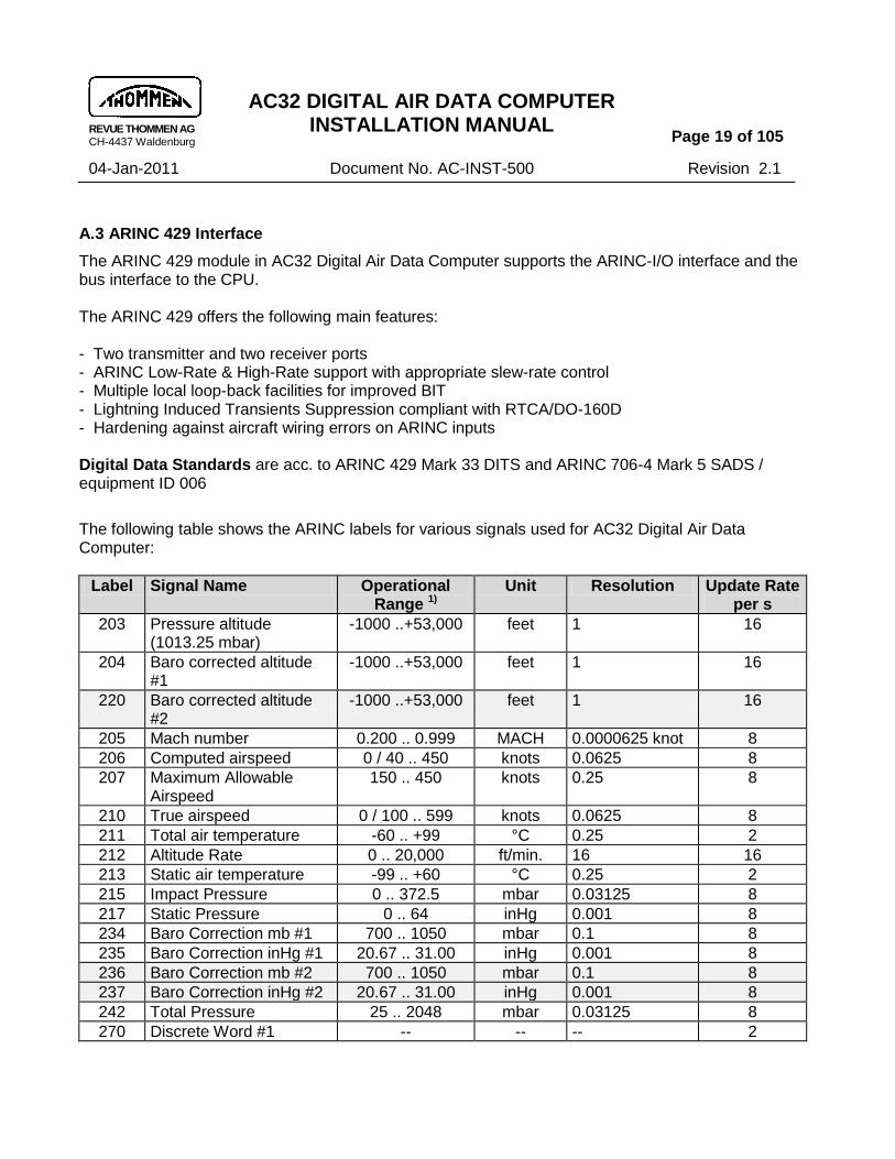
A.3 ARINC 429 Interface
The ARINC 429 module in AC32 Digital Air Data Computer supports the ARINC-I/O interface and the bus interface to the CPU. The ARINC 429 offers the following main features: - Two transmitter and two receiver ports - ARINC Low-Rate & High-Rate support with appropriate slew-rate control - Multiple local loop-back facilities for improved BIT - Lightning Induced Transients Suppression compliant with RTCA/DO-160D - Hardening against aircraft wiring errors on ARINC inputs Digital Data Standards are acc. to ARINC 429 Mark 33 DITS and ARINC 706-4 Mark 5 SADS / equipment ID 006
The following table shows the ARINC labels for various signals used for AC32 Digital Air Data Computer:
Label Signal Name Operational Range 1)
Unit Resolution Update Rate per s
203 Pressure altitude (1013.25 mbar)
-1000 ..+53,000 feet 1 16
204 Baro corrected altitude #1
-1000 ..+53,000 feet 1 16
220 Baro corrected altitude #2
-1000 ..+53,000 feet 1 16
205 Mach number 0.200 .. 0.999 MACH 0.0000625 knot 8
206 Computed airspeed 0 / 40 .. 450 knots 0.0625 8
207 Maximum Allowable Airspeed
150 .. 450 knots 0.25 8
210 True airspeed 0 / 100 .. 599 knots 0.0625 8
211 Total air temperature -60 .. +99 °C 0.25 2
212 Altitude Rate 0 .. 20,000 ft/min. 16 16
213 Static air temperature -99 .. +60 °C 0.25 2
215 Impact Pressure 0 .. 372.5 mbar 0.03125 8
217 Static Pressure 0 .. 64 inHg 0.001 8
234 Baro Correction mb #1 700 .. 1050 mbar 0.1 8
235 Baro Correction inHg #1 20.67 .. 31.00 inHg 0.001 8
236 Baro Correction mb #2 700 .. 1050 mbar 0.1 8
237 Baro Correction inHg #2 20.67 .. 31.00 inHg 0.001 8
242 Total Pressure 25 .. 2048 mbar 0.03125 8
270 Discrete Word #1 -- -- -- 2

REVUE THOMMEN AG CH-4437 Waldenburg
AC32 DIGITAL AIR DATA COMPUTER INSTALLATION MANUAL
Page 20 of 105
04-Jan-2011 Document No. AC-INST-500 Revision 2.1
Label Signal Name Operational Range 1)
Unit Resolution Update Rate per s
271 Discrete Word #2 -- -- -- 2
350 Maintenance Word #1 -- -- -- 2
351 Maintenance Word #2 -- -- -- 2
353 Indicated airspeed 0 / 40 .. 450 knots 0.0625 8
377 Equipment Identifier 006 -- -- 16
Table 4: ARINC429 Labels
A.4 RS-232 Serial Interface
The AC32 Digital Air Data Computer has a RS-232 interface for maintenance and calibration purposes only. This interface is not accessible for normal operation in the aircraft. The RS-232 Interface is provided for calibration and maintenance causes has the following transmission parameters: Baud Rate...…... 9600 kBit/s Start Bits...…..... 1 Data Bits....……. 8 Stop Bits.....…... 1 Parity...........…... None
A.5 Configuration Identification
The configuration identification defines a specific equipment configuration parameterized by the individual parameter lists for each AC32 equipment, which in turn explains the different parameter requested by the installer. So for every new AC32 equipment different Configuration ID number is designated.
CONFIGURATION ID 5001 (SAMPLE)
NOTE: Refer to Technical Checklist for Configuration ID (Identification) designation.

REVUE THOMMEN AG CH-4437 Waldenburg
AC32 DIGITAL AIR DATA COMPUTER INSTALLATION MANUAL
Page 21 of 105
04-Jan-2011 Document No. AC-INST-500 Revision 2.1
A.6 Operating Range, Limiting Values and Tolerances
Airdata Operating ranges Note 1)
BIT Limits MIN/MAX Note 2)
Tolerance
ALTITUDE related Values
ALTP Pressure Altitude
-1,000 ft … + 53,000 ft -305 m … + 16,154 m
-1,060 ft … + 53,590 ft -323 m … + 16,332 m
refer to Appendix II
ALTC Baro corrected Altitude
-1,000 ft … + 53,000 ft -305 m … + 16,154 m
-1,060 ft … + 53,590 ft -323 m … + 16,332 m
refer to Appendix II
ALT Rate Altitude rate
- 50,000 … + 50,000 ft/min
- 60,000 … + 60,000 ft/min
< 600 ft/min: ± 30 ft/min
> 600 ft/min: ± 5% rdg
Static Pressure 25 … 1100 mbar abs
20 … 1150 mbar abs
AIRSPEED related Values
IAS Indicated Airspeed
0 / 20 … 750 knots 0 … 765 knots refer to Appendix III
CAS Calibrated Airspeed (SSE corrected)
0 / 20 … 750 knots 0 … 765 knots refer to Appendix III
TAS True Airspeed (SSE corrected)
0 / 100 … 1000 knots 0 … 1015 knots ± 4 knots
VMO Maximum Allowable Airspeed
150 … 750 knots 150 … 750 knots --
Machi indicated Mach number
0 / 0.200 … 1.200 0 … 1.250 refer to Appendix IV
Impact Pressure 0 … 512 mbar
0 … 512 mbar
Total Pressure 25 … 2048 mbar abs
25 … 2048 mbar abs
TEMPERATURE related Values
Tti indicated Air Temperature
-- 214 … 374 K
TAT Total Air Temperature
- 60 … + 99 °C - 61 … + 100 °C ± 0.5 °C
SAT (OAT) Static Air Temperature
- 99 … + 60 °C - 100 … + 61 °C ± 1 °C
Table 5: Operating ranges, limiting values and tolerances

REVUE THOMMEN AG CH-4437 Waldenburg
AC32 DIGITAL AIR DATA COMPUTER INSTALLATION MANUAL
Page 22 of 105
04-Jan-2011 Document No. AC-INST-500 Revision 2.1
1) Operating range:
- Nominal operating range where equipment shall be within specs
2) BIT limits
- Transmitted values shall be within the parametrical BIT limits (tolerances for extreme environmental conditions have been considered)
- Values out of limits shall be handled according to the BIT-Matrix
B. Operating Modes
The following operating modes shall be provided:
Mode AC32 Digital Air Data Computer
Normal Operating Mode
Transmits/receives data via ARINC 429 labels
Maintenance Mode (RS-232 )
Allows initializing, calibrating, configuring and testing the equipment via the RS-232 interface.
Power Handling Modes
- Power on / initialisation - Power interrupt handling - Power return procedure (after Power Interrupt) - Power off return procedure
Failure Modes
- Critical Failures, which require an immediate shutdown in any case,
- Non Critical Failures, which degrade the operation of the equipment but allow a safe operation of the equipment functionality. At failure detection during startup BIT a shutdown shall be made.
- Tolerable Failures, which do not require a shutdown in any case.

REVUE THOMMEN AG CH-4437 Waldenburg
AC32 DIGITAL AIR DATA COMPUTER INSTALLATION MANUAL
Page 23 of 105
04-Jan-2011 Document No. AC-INST-500 Revision 2.1
Testing
A. Built-in-Test
A.1 BIT Overview
BIT When? Action Duration
Startup BIT
Primary power switched on after power off condition (reset released)
- test internal circuits < 10 s totally
Initiated BIT TEST/RESET activated - same as Startup BIT - same as Startup BIT
Continuous BIT Background operation, once within 10 s
- test internal circuits --
A.2 Start Up BIT
The flight equipment shall provide for a start-up BIT which will be activated upon application of primary or emergency power to the equipment. Faults detected shall be indicated as defined in Table 6 Fault Code Handling
A.3 Continuous BIT
The flight equipment can provide for a continuous BIT which shall run in the background during normal equipment operation. Any critical errors found during continuous BIT shall cause the equipment to stop. Non critical errors found during continuous BIT shall not stop operation. Fault codes are stored in memory for later retrieval during initiated BIT.

REVUE THOMMEN AG CH-4437 Waldenburg
AC32 DIGITAL AIR DATA COMPUTER INSTALLATION MANUAL
Page 24 of 105
04-Jan-2011 Document No. AC-INST-500 Revision 2.1
B. Failure Modes
B.1 Fault Code Handling
The operation mode of the instrument in case of fault indication shall be according to the following definition:
Failure class
BIT Action Warning Flag Valid Output
Signal
critical
Startup Initiated Continuous
- Warning Flag Valid Output Signal is set to LO
- ARINC 429 communication marks all labels as “failure warning”
- Failure Code is stored - instrument is set to idle mode
Fault indication: low signal
non critical / tolerable
Startup Initiated Continuous
- Warning Flag Valid Output Signal is set to LO
- ARINC 429 communication continues operation, invalid labels are marked as “failure warning”
- Failure Code is stored
Fault indication: low signal, as long as the Fault exists
Table 6: Fault code handling
Note: If a non critical BIT allows to continue operation but invalid values would lead to wrong calculations (e.g. division by zero) the calculations can not be made and ARINC 429 labels can be marked as “FW” Failure Warning (SSM)

REVUE THOMMEN AG CH-4437 Waldenburg
AC32 DIGITAL AIR DATA COMPUTER INSTALLATION MANUAL
Page 25 of 105
04-Jan-2011 Document No. AC-INST-500 Revision 2.1
B.2 Primary Power Fail Indication (optional)
Primary Power Fail indicates loss of primary power 28 VDC only if emergency power is available. Primary Power Fail is detected by the Voltage Comparator Input (refer to the external electrical connector section IV E.1.1) and must be connected to the primary power line in the external connector.
Switching Thresholds (± 5%) Indication
< 25 % of specified Primary Power voltage FAIL
> 60 % of specified Primary Power voltage normal
Primary
Power Fail
Discrete
OUT
Primary
Power
Emergency
Power
Voltage
Comparator InputAC32
H L
b EE
J KG v
Figure 4: Primary Power Fail
NOTE: For the individual type execution of Air Data Computer, refer Appendix II Air Data
Computer Execution.

REVUE THOMMEN AG CH-4437 Waldenburg
AC32 DIGITAL AIR DATA COMPUTER INSTALLATION MANUAL
Page 26 of 105
04-Jan-2011 Document No. AC-INST-500 Revision 2.1
SECTION III
Approvals
A. General
The approval of the AC32 Digital Air Data Computer equipment is being accomplished under certified TSO-C106 / TSO-C88a. NOTE: The TSO identifies the minimum performance standards, tests and other conditions
applicable for issuance of design and production approval of the equipment and does not specifically identify acceptable conditions for installation. It is the responsibility of those desiring to install this equipment either on or with in the specific type or class of aircraft / rotorcraft to determine that the aircraft / rotorcraft installation conditions are with in the TSO standards.
B. Instructions for Continued Airworthiness
Maintenance Requirements – Instructions for Continued Airworthiness under FAR 23.1529, 25.1529, 27.1529 and 29.1529
Modification of an fixed wing or rotor wing aircraft by this installation obligates the aircraft operator to include the maintenance information provided by this document in the operator‟s Aircraft Maintenance Manual and the operator‟s Aircraft Scheduled Maintenance Program for the schedule maintenance instructions.
(1) Maintenance Manual information for the AC32 (description, Installation, testing, etc.) is contained in AC32 Digital Air Data Computer Installation and Operation manual AC-INST-500
(2) The equipment part number and other necessary part numbers contained in the installation manual should be placed into the aircraft operator‟s appropriate airplane Illustrated Parts Catalog (IPC).
(3) Wiring diagram information contained in this manual should be placed into the aircraft operator‟s appropriate airplane Wiring Diagram Manuals.
(4) Scheduled Maintenance Program tasks to be added to the aircraft operator‟s appropriate airplane maintenance program are as follows:
a. Recommended Periodic Scheduled Servicing Tasks: On Condition
b. Recommended Periodic Scheduled Preventative Maintenance Tests/Checks to determine System Condition and/or Latent Failures: On Condition
c. Recommended Periodic Inspections: On Condition
d. Recommended Periodic Structural Inspections: On Condition
(5) Recalibration Interval
The flight equipment has the following recalibration intervals: On Condition

REVUE THOMMEN AG CH-4437 Waldenburg
AC32 DIGITAL AIR DATA COMPUTER INSTALLATION MANUAL
Page 27 of 105
04-Jan-2011 Document No. AC-INST-500 Revision 2.1
NOTE: Unit performs continuous self-testing (BIT) and monitoring; any detected failures are annunciated.
C. Environmental Qualification
The AC32 Digital Air Data Computer shall be operated within the limits specified under the following environmental conditions:
Environmental Criteria Requirement RTCA/DO-160D
Remarks
Temperature & Altitude Temperature: Continuous operation Ground Survival Temperature Operating Low Temperature Operating High Temperature Short Time Operating High Temperature Altitude Decompression Overpressure static port of the instrument
RTCA/DO-160D Section 4.0 Cat. [D2] from -55 to +70 °C from -55 to +85 °C Section 4.5.1 -55 °C Section 4.5.3 +55 °C Section 4.5.2 +70 °C Section 4.6.1 50,000 ft Section 4.6.2 50,000 ft Section 4.6.3 -15,000 ft
Temperature Variation RTCA/DO-160D Section 5.0 Cat. B (5 °C/min.)
Humidity up to 95 %rH RTCA/DO-160D Section 6.0 Cat. B
Shock and Crash Safety: Operational Shock
RTCA/DO-160D Section 7.0 Cat. B 6g, 11 ms
Crash Safety: Impulse Sustained
Section 7.3 20g, 11 ms

REVUE THOMMEN AG CH-4437 Waldenburg
AC32 DIGITAL AIR DATA COMPUTER INSTALLATION MANUAL
Page 28 of 105
04-Jan-2011 Document No. AC-INST-500 Revision 2.1
Environmental Criteria Requirement RTCA/DO-160D
Remarks
Vibration
RTCA/DO-160D Section 8.0 Cat. [(TB1)(TR)]/[(SL)(SM)] Cat. [UG]
Curves F & F1 without shock mounts
Explosion RTCA/DO-160D Section 9.0 Cat. X (Environment II)
no test required
Waterproofness RTCA/DO-160D Section 10.0 Cat. W
Fluids Susceptibility RTCA/DO-160D Section 11.0 Cat. F
Solvent and cleaning Fluids Lubrificating Oils
Sand and Dust: Sand and dust particles as encountered in desert areas
RTCA/DO-160D Section 12.0 Cat. D
Fungus: Fungus growth as encountered in tropical climates
RTCA/DO-160D Section 13.0 Cat. F
Salt Spray: Exposure to salt-sea atmosphere
RTCA/DO-160D Section 14.0 Cat. S
Magnetic Effect RTCA/DO-160D Section 15.0 Cl. Z < 0.3m
Power Characteristics DC Normal operating conditions (DC)
RTCA/DO-160D Section 16.0 Cat. Z
Max. voltage Nominal voltage Min. voltage Emergency operation voltage level
30.3 VDC 28.0 VDC 22.0 VDC 18.0 VDC
Ripple voltage
Momentary power interruptions up to 1000 ms
Normal surge voltage up to 50 V for 50 ms Engine starting undervoltage operation 10.0 to 20.5 VDC Abnormal operating conditions (DC)
Voltage steady state Maximum Minimum
32.2 VDC 20.5 VDC
Low voltage conditions Momentary undervoltage operation
0 to 20.5 VDC 12.0 VDC up to 7 s
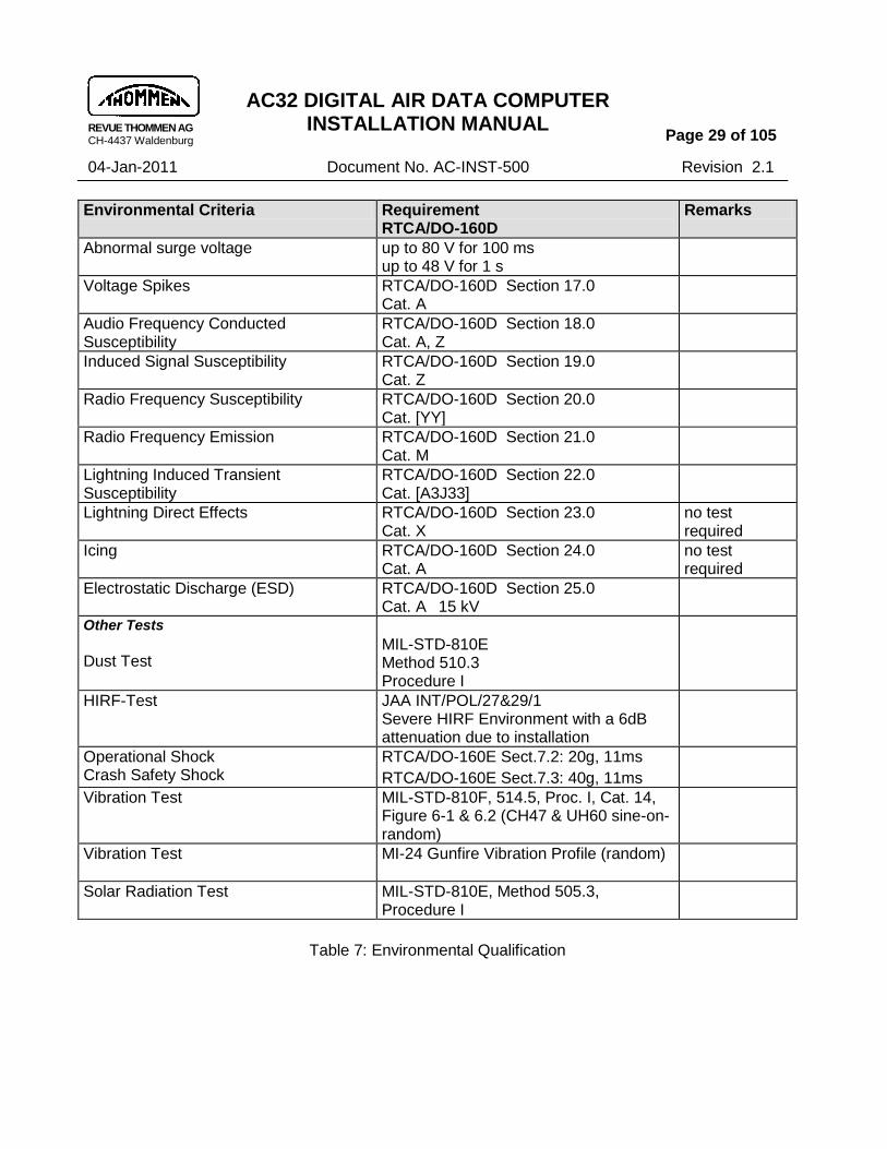
REVUE THOMMEN AG CH-4437 Waldenburg
AC32 DIGITAL AIR DATA COMPUTER INSTALLATION MANUAL
Page 29 of 105
04-Jan-2011 Document No. AC-INST-500 Revision 2.1
Environmental Criteria Requirement RTCA/DO-160D
Remarks
Abnormal surge voltage up to 80 V for 100 ms up to 48 V for 1 s
Voltage Spikes RTCA/DO-160D Section 17.0 Cat. A
Audio Frequency Conducted Susceptibility
RTCA/DO-160D Section 18.0 Cat. A, Z
Induced Signal Susceptibility RTCA/DO-160D Section 19.0 Cat. Z
Radio Frequency Susceptibility RTCA/DO-160D Section 20.0 Cat. [YY]
Radio Frequency Emission RTCA/DO-160D Section 21.0 Cat. M
Lightning Induced Transient Susceptibility
RTCA/DO-160D Section 22.0 Cat. [A3J33]
Lightning Direct Effects RTCA/DO-160D Section 23.0 Cat. X
no test required
Icing RTCA/DO-160D Section 24.0 Cat. A
no test required
Electrostatic Discharge (ESD) RTCA/DO-160D Section 25.0 Cat. A 15 kV
Other Tests Dust Test
MIL-STD-810E Method 510.3 Procedure I
HIRF-Test
JAA INT/POL/27&29/1 Severe HIRF Environment with a 6dB attenuation due to installation
Operational Shock Crash Safety Shock
RTCA/DO-160E Sect.7.2: 20g, 11ms
RTCA/DO-160E Sect.7.3: 40g, 11ms
Vibration Test MIL-STD-810F, 514.5, Proc. I, Cat. 14, Figure 6-1 & 6.2 (CH47 & UH60 sine-on-random)
Vibration Test MI-24 Gunfire Vibration Profile (random)
Solar Radiation Test MIL-STD-810E, Method 505.3, Procedure I
Table 7: Environmental Qualification

REVUE THOMMEN AG CH-4437 Waldenburg
AC32 DIGITAL AIR DATA COMPUTER INSTALLATION MANUAL
Page 30 of 105
04-Jan-2011 Document No. AC-INST-500 Revision 2.1
C.1 Electromagnetic Environment (EME)
The AC32 Digital Air Data Computer is designed, analyzed, installed, and tested to perform and fulfill the aircraft electromagnetic environment (EME) requirements without any malfunction or degradation in performance.
C.2 Electromagnetic compatibility (EMC)
The AC32 Digital Air Data Computer proves electromagnetic compatibility (EMC). Which means the flight instrument performs its individually designed functions in a common EME without causing or suffering unacceptable degradation due to electromagnetic interference (EMI) to or from other equipment/systems in the same environment in accordance with the overall requirements.
C.3 Electromagnetic interference (EMI)
The generation of EMI by the flight equipment and the susceptibility of the flight equipment to EMI is controlled to the limits of RTCA/DO-160D and as modified by this specification. These requirements are met in all flight equipment operating modes.

REVUE THOMMEN AG CH-4437 Waldenburg
AC32 DIGITAL AIR DATA COMPUTER INSTALLATION MANUAL
Page 31 of 105
04-Jan-2011 Document No. AC-INST-500 Revision 2.1
SECTION IV
Installation
A. General
Installation data in this section consists of pre-installation checks, Electrical Interface, system interconnect diagrams and digital interface data to assure satisfactory performance of AC32 Digital Air Data Computer.
NOTE: Refer to Section I part D for Mechanical Installation details.
B. Unpacking and Inspecting
Unpack the equipment carefully and make a visual inspection of the instrument for possible shipping damage. If a claim for damage is to be made, save the original packing carton and materials to substantiate the claim.
C. Pre and Post Installation Check
Before installing the equipment in the aircraft, check for the applicable configuration ID and correct MOD status to ensure that the equipment meets performance specifications. The AC32 Digital Air Data Computer equipment does not require any in- aircraft adjustment. All adjustments procedures are accomplished by the manufacturer.
D. Electrical Interface
D.1 Overview of electrical interface
The following are the electrical interfaces for AC32 Digital Air Data Computer: - Primary and Emergency Power Supply - Digital Communication Interfaces (ARINC 429 data bus, ICAO Encoder, RS-232 Maintenance IF) - Discrete I/O‟s - TAT (Total Air Temperature) Probe input
D.2 Power Control (DC Primary)
The AC32 Digital Air Data Computer is designed for 28 VDC power supply in accordance with RTCA/DO-160D Section 16.0 under Category Z or Category B respectively. An optional secondary 28 VDC emergency power supply input is drawn from the emergency bus is provided in case of primary power supply failure.

REVUE THOMMEN AG CH-4437 Waldenburg
AC32 DIGITAL AIR DATA COMPUTER INSTALLATION MANUAL
Page 32 of 105
04-Jan-2011 Document No. AC-INST-500 Revision 2.1
D.3 Power Consumption
The following table shows values of power consumed by AC32 equipment with the full operating functionality. The equipment e.g. without ARINC429 module or without sensors have less power consumption. The power consumption by the AC32 flight equipment at different stages of operation are shown below in the table:
Operation Power Consumption
During startup max. 7 W
Normal operation max. 5 W
max. current 0.7 A
Note: Recommended CB (Circuit Breaker) of 1 Ampere.
D.4 Power Fails indication
In case of power fail or switching off the equipment‟s power supply the warning flag valid output signal (WFVOUTS) sets signal to “LO”.
D.5 Groundings and Shielding
Groundings
All the ground strap chasis grounds aircraft, twisted shielded cables/wires and power cables/wires (See section of wiring diagram for the grounding cables/wires) should be carefully grounded (aircraft ground & shield grounds) such a manner in order to : - prevent ground loops and common ground returns for signals and power circuits - provide effective shielding for signal circuits - minimize EMI (Electromagnetic Interference) during the engine runup, and - protect personnel from electrical shock hazards. Note: All externally exposed metal parts, shields, connectors, etc. are grounded to the
chassis ground.
REVUE THOMMEN AG CH-4437 Waldenburg
AC32 DIGITAL AIR DATA COMPUTER INSTALLATION MANUAL
Page 33 of 105
04-Jan-2011 Document No. AC-INST-500 Revision 2.1
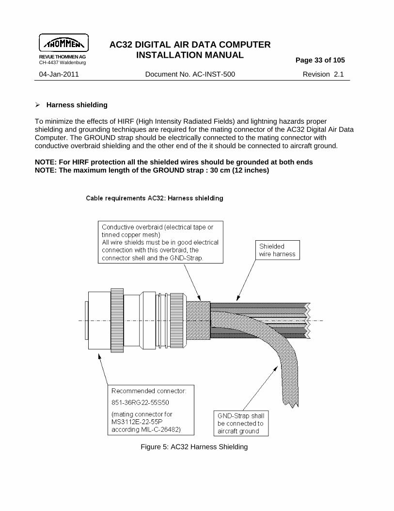
Harness shielding To minimize the effects of HIRF (High Intensity Radiated Fields) and lightning hazards proper shielding and grounding techniques are required for the mating connector of the AC32 Digital Air Data Computer. The GROUND strap should be electrically connected to the mating connector with conductive overbraid shielding and the other end of the it should be connected to aircraft ground. NOTE: For HIRF protection all the shielded wires should be grounded at both ends NOTE: The maximum length of the GROUND strap : 30 cm (12 inches)
Figure 5: AC32 Harness Shielding
REVUE THOMMEN AG CH-4437 Waldenburg
AC32 DIGITAL AIR DATA COMPUTER INSTALLATION MANUAL
Page 34 of 105
04-Jan-2011 Document No. AC-INST-500 Revision 2.1
D.6 Power common leads
equipment ground (common) shall be connected to the power common leads (See Section IV- E Electrical Connector)
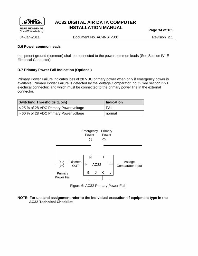
D.7 Primary Power Fail Indication (Optional)
Primary Power Failure indicates loss of 28 VDC primary power when only if emergency power is available. Primary Power Failure is detected by the Voltage Comparator Input (See section IV- E electrical connector) and which must be connected to the primary power line in the external connector.
Switching Thresholds (± 5%) Indication
< 25 % of 28 VDC Primary Power voltage FAIL
> 60 % of 28 VDC Primary Power voltage normal
Primary
Power Fail
Discrete
OUT
Primary
Power
Emergency
Power
Voltage
Comparator InputAD32
H L
b EE
J KG v
Figure 6: AC32 Primary Power Fail
NOTE: For use and assignment refer to the individual execution of equipment type in the AC32 Technical Checklist.
AC32

REVUE THOMMEN AG CH-4437 Waldenburg
AC32 DIGITAL AIR DATA COMPUTER INSTALLATION MANUAL
Page 35 of 105
04-Jan-2011 Document No. AC-INST-500 Revision 2.1
E. Electrical connector
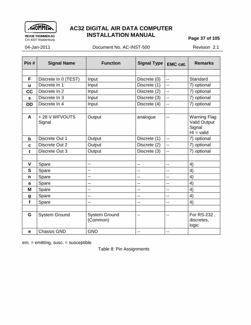
E.1 Pin Assignments
The electrical connectors for interfacing the AC32 with aircraft wiring are round type connectors. NOTE: The mating connector should be shielded. The below shown table shows the pin numbers and its definition/functionality for the mating Electrical Connector (MS Number 3126F-22-55S) :
Pin # Signal Name Function Signal Type EMC cat. Remarks
L Primary Power supply
Primary Power supply
analogue em./ susc.
28VDC
K Power return Power return analogue em./ susc.
5)
H Emergency Power supply
Secondary Power supply
analogue em./ susc.
optional 28VDC
J Power return Power return analogue em./ susc.
5), optional
U Spare -- -- -- 4)
T Spare -- -- -- 4)
R TAT probe, supply hi TAT probe, supply high analogue susc. optional, supplied by AC32,
ca. 1 mADC
2-/3-/4-wire connection
p TAT probe, supply lo TAT probe, supply low analogue susc.
k TAT probe, sense hi TAT probe, sense high analogue susc.
m TAT probe, sense lo TAT probe, sense low analogue susc.
h RS-232 TxD Serial IF Transmit data -- 1),3) only for maintenance
w RS-232 RxD Serial IF Receive data --
W ARINC429 RxD 1A
(RS422 RxD 1A)
Serial Interface Bus Receive Channel 1
data bus em./ susc.

REVUE THOMMEN AG CH-4437 Waldenburg
AC32 DIGITAL AIR DATA COMPUTER INSTALLATION MANUAL
Page 36 of 105
04-Jan-2011 Document No. AC-INST-500 Revision 2.1
Pin # Signal Name Function Signal Type EMC cat. Remarks
X ARINC429 RxD 1B
(RS422 RxD 1B)
Serial Interface Bus Receive Channel 1
data bus em./ susc.
Y ARINC429 RxD 2A
(RS422 RxD 2A)
Serial Interface Bus Receive Channel 2
data bus em./ susc.
D ARINC429 RxD 2B
(RS422 RxD 2B)
Serial Interface Bus Receive Channel 2
data bus em./ susc.
B ARINC429 TxD 1A
(RS422 TxD 1A)
Serial Interface Bus Transmit Channel 1
data bus em./susc.
C ARINC429 TxD 1B
(RS422 TxD 1B)
Serial Interface Bus Transmit Channel 1
data bus em./susc.
q ARINC429 TxD 2A
(RS422 TxD 2A)
Serial Interface Bus Transmit Channel 2
data bus em./susc.
r ARINC429 TxD 2B
(RS422 TxD 2B)
Serial Interface Bus Transmit Channel 2
data bus em./susc.
y ICAO Code D4 Output
Logic em./susc.
shielded
2)
GG ICAO Code A1 Output
FF ICAO Code A2 Output
BB ICAO Code A4 Output
HH ICAO Code B1 Output
i ICAO Code B2 Output
AA ICAO Code B4 Output
z ICAO Code C1 Output
j ICAO Code C2 Output
P ICAO Code C4 Output
d ICAO Code Strobe Input Discrete (5)
Z Spare -- -- -- 4)
E Spare -- -- -- 4)
x Spare -- -- -- 4)
N Spare -- -- -- 4)
EE Voltage Comparator Input High
Input analogue -- 8) optional 5 / 28 VDC
v Voltage Comparator Input Low
Input analogue -- 8) optional
REVUE THOMMEN AG CH-4437 Waldenburg
AC32 DIGITAL AIR DATA COMPUTER INSTALLATION MANUAL
Page 37 of 105
04-Jan-2011 Document No. AC-INST-500 Revision 2.1
Pin # Signal Name Function Signal Type EMC cat. Remarks
F Discrete In 0 (TEST) Input Discrete (0) -- Standard
u Discrete In 1 Input Discrete (1) -- 7) optional
CC Discrete In 2 Input Discrete (2) -- 7) optional
s Discrete In 3 Input Discrete (3) -- 7) optional
DD Discrete In 4 Input Discrete (4) -- 7) optional
A + 28 V WFVOUTS Signal
Output analogue -- Warning Flag Valid Output Signal HI = valid
b Discrete Out 1 Output Discrete (1) -- 7) optional
c Discrete Out 2 Output Discrete (2) -- 7) optional
t Discrete Out 3 Output Discrete (3) -- 7) optional
V Spare -- -- -- 4)
S Spare -- -- -- 4)
n Spare -- -- -- 4)
a Spare -- -- -- 4)
M Spare -- -- -- 4)
g Spare -- -- -- 4)
f Spare -- -- -- 4)
G System Ground System Ground (Common)
-- -- For RS-232 , discretes, logic
e Chassis GND GND -- --
em. = emitting, susc. = susceptible
Table 8: Pin Assignments

REVUE THOMMEN AG CH-4437 Waldenburg
AC32 DIGITAL AIR DATA COMPUTER INSTALLATION MANUAL
Page 38 of 105
04-Jan-2011 Document No. AC-INST-500 Revision 2.1
Remarks
1) Short-circuit RS-232 TxD and RxD on aircraft installation (jumper aircraft connector pins) 2) To avoid “CODE” flag indication on the display discrete input no. 5 (connector pin no. “d”) must
be grounded 3) Transmit and Receive Signals are seen from the AC32 view 4) Reserved for future development 5) Power Return for primary and secondary supply are connected internally 6) -- 7) For use and assignment refer to the individual execution of your type in the technical checklist. 8) Voltage Comparator Input used for „Primary Power Fail detection‟
NOTE: For use refer to the individual execution of your type in Technical Checklist.
E.2 Wiring Diagram
NOTE 1: For wiring diagram refer to the next page. NOTE 2: Loop the Primary Power Return pin number “K” to COMMON pin number “G” with
20 AWG on the connector, to avoid the intermittent occurrence of Fault code FC010 on AC32 Digital Air Data Computer.

REVUE THOMMEN AG CH-4437 Waldenburg
AC32 DIGITAL AIR DATA COMPUTER INSTALLATION MANUAL
Page 39 of 105
04-Jan-2011 Document No. AC-INST-500 Revision 2.1
Cable requirements for RF SUSCEPTIBILITY acc. RTCA DO-160D, Sect. 20, Cat. YY and Severe HIRF-Environment according to INT/POL/27&29/1 with a 6 dB attenuation
Figure 7: Wiring Diagram

REVUE THOMMEN AG CH-4437 Waldenburg
AC32 DIGITAL AIR DATA COMPUTER INSTALLATION MANUAL
Page 40 of 105
04-Jan-2011 Document No. AC-INST-500 Revision 2.1
E.3 Data Link Interface Diagram
The Diagram shows an example of data communication with flight Displays.
Figure 8: Digital Air Data Computer Communication
AC32
digital
Autopilot
Transponder
ICAO Code
SP
ARINC 429
DisplayDisplay
TAT
ARINC 429
ARINC 429
ARINC 429
Discrete I/O's
Captain Co-Pilot

REVUE THOMMEN AG CH-4437 Waldenburg
AC32 DIGITAL AIR DATA COMPUTER INSTALLATION MANUAL
Page 41 of 105
04-Jan-2011 Document No. AC-INST-500 Revision 2.1
F. TAT Probe Interface
The TAT (Total Air Temperature) probe according to ARINC 706-4 Section 4.8 (500 Ohm) is connected to an input of the instrument with 2-/3- or 4-wire connection according to the configuration required. For 2- or 3-wire connections the wire resistance can be stored and is compensated by the equipment (Default correction value 0 Ohm). Temperature range is - 60 … + 99°C
TTi Resistance Pt 500 acc. to ARINC 706-4 Table 5-1
Indicated Total Air Temperature °C
Ohm
-60 381.64
-30 441.16
0 500.00
30 558.21
60 615.79 99 689.72
Table 9: Resistance Pt 500
Pin #
Signal Name 2-wire connection
3-wire connection
4-wire connection
k
TAT probe, sense high
1)
R TAT probe, supply high
p TAT probe, supply low
1) 1)
m TAT probe, sense low
Table 10: TAT Signals
1) connect both pins at the connector

REVUE THOMMEN AG CH-4437 Waldenburg
AC32 DIGITAL AIR DATA COMPUTER INSTALLATION MANUAL
Page 42 of 105
04-Jan-2011 Document No. AC-INST-500 Revision 2.1
NOTES: - For use refer to the individual execution of your type in Technical Checklist. - Pt 100 configuration also available. - AD3X.() is capable of TAT probe input. - If the installation does not require a TAT probe a 500 Ohm resistor can replace the TAT probe at the input to avoid FC039.
NOTE:
Manufacturers of temperature probes shall be contacted for the evaluation of the correct TAT or OAT probe. The system installer shall be responsible for the selection of the probe. This needs to be evaluated on the aircraft level. The specification of the selected probe is required.
An OAT probe usually can be used up to airspeed 200 knots. Above 200 knots airspeed and at icing conditions it is required to use a heated TAT probe (to enable deicing).
F.1 TAT Synchronisation
If no TAT probe is connected directly to the equipment the parametric TAT synchronisation reads the air temperature from ARINC 429 label 211 (TAT) on channel RxD1 or RxD2 depending on availability. The TAT handling is according to the following table:
TAT Source TAT Use Self sensed TAT value
Received TAT value (Label 211 on RxD1)
Received TAT value (Label 211 on RxD2)
Used source for calculation of SAT and TAS
Handling of TAT BIT FC 039
SSM of transmitted Label 211
Yes X X Self sensed TAT
value No
Normal Operation
No Yes X Received TAT
value (Label 211 on RxD1)
No
Failure Warning for 0.5 s if loss of TAT probe is detected, then normal operation
No No Yes Received TAT
value (Label 211 on RxD2)
No
Failure Warning for 0.5 s if loss of TAT probe is detected, then normal operation
No No No None Yes Failure Warning
Note: X = don‟t care

REVUE THOMMEN AG CH-4437 Waldenburg
AC32 DIGITAL AIR DATA COMPUTER INSTALLATION MANUAL
Page 43 of 105
04-Jan-2011 Document No. AC-INST-500 Revision 2.1
G. Digital Data Interfaces
G.1 ARINC 429 Data bus Interface
Digital Data Standards are acc. to ARINC 429 Mark 33 DITS and ARINC 706-4 Mark 5 SADS / equipment ID 006
Label Signal Name Operational Range 1)
Equip-ment
Resolution Update Rate per s
203 Pressure altitude (1013.25 mbar)
-1000 ..+53,000 feet 1 16
204 Baro corrected altitude #1 -1000 ..+53,000 feet 1 16
220 Baro corrected altitude #2 -1000 ..+53,000 feet 1 16
205 Mach number 0.200 .. 0.999 MACH 0.0000625 knot
8
206 Computed airspeed 0 / 40 .. 450 knots 0.0625 8
207 Maximum Allowable Airspeed
150 .. 450 knots 0.25 8
210 True airspeed 0 / 100 .. 599 knots 0.0625 8
211 Total air temperature -60 .. +99 °C 0.25 2
212 Altitude Rate 0 .. 50,000 ft/min. 16 16
213 Static air temperature -99 .. +60 °C 0.25 2
215 Impact Pressure 0 .. 372.5 mbar 0.03125 8
217 Static Pressure 0 .. 64 inHg 0.001 8
234 Baro Correction mb #1 700 .. 1050 mbar 0.1 8
235 Baro Correction inHg #1 20.67 .. 31.00 inHg 0.001 8
236 Baro Correction mb #2 700 .. 1050 mbar 0.1 8
237 Baro Correction inHg #2 20.67 .. 31.00 inHg 0.001 8
242 Total Pressure 25 ..2048 mbar 0.03125 8
270 Discrete Word #1 -- -- -- 2
350 Maintenance Word #1 -- -- -- 2
351 Maintenance Word #2 -- -- -- 2
353 Indicated airspeed 0 / 40 .. 450 knots 0.0625 8
377 Equipment Identifier 006 -- -- 16
Table 11: ARINC 429 Labels
1) Operational ranges are defined to meet customer requirements.
NOTE: For use and assignment refer to the individual execution of equipment type.

REVUE THOMMEN AG CH-4437 Waldenburg
AC32 DIGITAL AIR DATA COMPUTER INSTALLATION MANUAL
Page 44 of 105
04-Jan-2011 Document No. AC-INST-500 Revision 2.1
G.2 ARINC 429 Bit Rate & Bus Load
The ARINC 429 data bus is designed for: - High Speed: 100 kbits/s, half load for both transmit channels
(max. bus load per transmitter 1 kOhm / 9.5 nF) Optionally it can be configured for: - Low Speed: 12.5 kbits/s, full load for both transmit channels
(max. bus load per transmitter 260 Ohm / 45 nF) Note: In real installations the maximum bus load is determined by impedance of cabling and receivers. The installer shall make provisions to allocate the bus load to both ARINC 429 transmit channels of the AC32. This shall be taken into account especially at high speed bit rate and with more than 7 receivers per transmit channel. In individual installations the impedance of receivers connected to the AC32 could be much higher than expected. The following table shows the ARINC 429 labels with I/O transfer channels:
Label Signal Name I/O Transfer channel Digital ADC
203 Pressure altitude (1013.25 mbar) TxD1/TxD2 --
204 Baro corrected altitude #1 TxD1/TxD2 --
220 Baro corrected altitude #2 TxD1/TxD2 --
205 Mach number TxD1/TxD2 --
206 Computed airspeed TxD1/TxD2 --
207 Maximum Allowable Airspeed TxD1/TxD2 --
210 True airspeed TxD1/TxD2 --
211 Total air temperature TxD1/TxD2 --
212 Altitude Rate TxD1/TxD2 --
213 Static air temperature TxD1/TxD2 --
215 Impact Pressure TxD1/TxD2 --
217 Static Pressure TxD1/TxD2 --
234 Baro Correction mb #1 TxD1/TxD2 RxD1
235 Baro Correction inHg #1 TxD1/TxD2 RxD1
236 Baro Correction mb #2 TxD1/TxD2 RxD1
237 Baro Correction inHg #2 TxD1/TxD2 RxD1
242 Total Pressure TxD1/TxD2 --
270 Discrete Word #1 TxD1/TxD2 --
271 Discrete Word #2 (provision) -- --
350 Maintenance Word #1 TxD1/TxD2 --

REVUE THOMMEN AG CH-4437 Waldenburg
AC32 DIGITAL AIR DATA COMPUTER INSTALLATION MANUAL
Page 45 of 105
04-Jan-2011 Document No. AC-INST-500 Revision 2.1
Label Signal Name I/O Transfer channel Digital ADC
351 Maintenance Word #2 (provision) -- --
353 Indicated airspeed TxD1/TxD2 --
377 Equipment Identifier TxD1/TxD2 --
Table 12: ARINC 429 I/O Transfer labels
The following table is for Baro Synchronization :
Label Function I/O Transfer channel Digital ADC
234 / 235 Baro Synch. TxD1/TxD2 RxD1
Table 13: ARINC 429 I/O Transfer for Baro Correction
G.3 ARINC Label Formats
Label Signal Name Format according to
203 Pressure altitude (1013.25 mbar)
ARINC 429 Mark 33 DITS equipment ID 006
204 Baro corrected altitude #1
220 Baro corrected altitude #2
205 Mach number
206 Computed airspeed
207 Maximum Allowable Airspeed
210 True airspeed
211 Total air temperature
212 Altitude Rate
213 Static air temperature
215 Impact Pressure
217 Static Pressure
234 Baro Correction mb #1
235 Baro Correction inHg #1
236 Baro Correction mb #2
237 Baro Correction inHg #2
242 Total Pressure
377 Equipment Identifier
270 Discrete Word #1 Section IV Part 1 Para G.3.1
350 Maintenance Word #1 Section IV Part 1 Para G.3.2
351 Maintenance Word #2 Section IV Part 1 Para G,3,2
353 Indicated airspeed Section IV Part 1 Para G.3.4
Table 14: ARINC 429 Labels Format
REVUE THOMMEN AG CH-4437 Waldenburg
AC32 DIGITAL AIR DATA COMPUTER INSTALLATION MANUAL
Page 46 of 105
04-Jan-2011 Document No. AC-INST-500 Revision 2.1
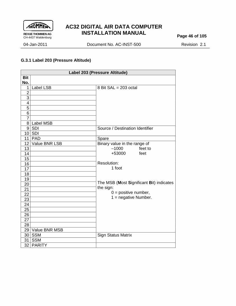
G.3.1 Label 203 (Pressure Altitude)
Label 203 (Pressure Altitude)
Bit No.
1 Label LSB 8 Bit SAL = 203 octal
2
3
4
5
6
7
8 Label MSB
9 SDI Source / Destination Identifier
10 SDI
11 PAD Spare
12 Value BNR LSB Binary value in the range of –1000 feet to +53000 feet Resolution: 1 foot The MSB (Most Significant Bit) indicates the sign: 0 = positive number, 1 = negative Number.
13
14
15
16
17
18
19
20
21
22
23
24
25
26
27
28
29 Value BNR MSB
30 SSM Sign Status Matrix
31 SSM
32 PARITY

REVUE THOMMEN AG CH-4437 Waldenburg
AC32 DIGITAL AIR DATA COMPUTER INSTALLATION MANUAL
Page 47 of 105
04-Jan-2011 Document No. AC-INST-500 Revision 2.1
G.3.2 Label 204 (Baro corrected altitude #1)
Label 204 (Baro corrected altitude #1)
Bit No.
1 SAL LSB 8 Bit SAL = 204 octal
2
3
4
5
6
7
8 SAL MSB
9 SDI Source / Destination Identifier
10 SDI
11 PAD Spare bit
12 Value BNR LSB Binary value in the range of –1000 feet to +53000 feet Resolution: 1 foot The MSB (Most Significant Bit) indicates the sign: 0 = positive number 1 = negative Number
13
14
15
16
17
18
19
20
21
22
23
24
25
26
27
28
29 Value BNR MSB
30 SSM Sign Status Matrix
31 SSM
32 PARITY

REVUE THOMMEN AG CH-4437 Waldenburg
AC32 DIGITAL AIR DATA COMPUTER INSTALLATION MANUAL
Page 48 of 105
04-Jan-2011 Document No. AC-INST-500 Revision 2.1
G.3.3 Label 220 Baro corrected altitude #2
Label 220 (Baro corrected altitude #2)
Bit No.
1 SAL LSB 8 Bit SAL = 220 octal
2
3
4
5
6
7
8 SAL MSB
9 SDI Source / Destination Identifier
10 SDI
11 PAD Spare Bit
12 Value BNR LSB Binary value in the range of –1000 feet to +53000 feet Resolution: 1 foot The MSB (Most Significant Bit) indicates the sign: 0 = positive number 1 = negative Number
13
14
15
16
17
18
19
20
21
22
23
24
25
26
27
28
29 Value BNR MSB
30 SSM Sign Status Matrix
31 SSM
32 PARITY

REVUE THOMMEN AG CH-4437 Waldenburg
AC32 DIGITAL AIR DATA COMPUTER INSTALLATION MANUAL
Page 49 of 105
04-Jan-2011 Document No. AC-INST-500 Revision 2.1
G.3.4 Label 205 (Mach number)
Label 205 (Mach number)
Bit No.
1 SAL LSB 8 Bit SAL = 205 octal
2
3
4
5
6
7
8 SAL MSB
9 SDI Source / Destination Identifier
10 SDI
11 PAD Spare Bits
12 PAD
13 Value BNR LSB Range: 0.200 to 0.999
Resolution: 0.0000625
14
15
16
17
18
19
20
21
22
23
24
25
26
27
28
29 Value BNR MSB
30 SSM Sign Status Matrix
31 SSM
32 PARITY

REVUE THOMMEN AG CH-4437 Waldenburg
AC32 DIGITAL AIR DATA COMPUTER INSTALLATION MANUAL
Page 50 of 105
04-Jan-2011 Document No. AC-INST-500 Revision 2.1
G.3.5 Label 206 (Computed air speed)
Label 206 (Computed air speed)
Bit No.
1 SAL LSB 8 Bit SAL = 206 octal
2
3
4
5
6
7
8 SAL MSB
9 SDI Source / Destination Identifier
10 SDI
11 PAD Spare Bits
12 PAD
13 PAD
14 PAD
15 Value BNR LSB Range: 0 / 40 to 450 knots
Resolution: 0.0625 knots
16
17
18
19
20
21
22
23
24
25
26
27
28
29 Value BNR MSB
30 SSM Sign Status Matrix
31 SSM
32 PARITY

REVUE THOMMEN AG CH-4437 Waldenburg
AC32 DIGITAL AIR DATA COMPUTER INSTALLATION MANUAL
Page 51 of 105
04-Jan-2011 Document No. AC-INST-500 Revision 2.1
G.3.6 Label 207 (Maximum allowable air speed)
Label 207 (Maximum allowable air speed)
Bit No.
1 SAL LSB 8 Bit SAL = 207 octal
2
3
4
5
6
7
8 SAL MSB
9 SDI Source / Destination Identifier
10 SDI
11 PAD Spare Bits
12 PAD
13 PAD
14 PAD
15 PAD
16 PAD
17 Value BNR LSB Range: 150 to 450 knots
Resolution: 0.25 knots
18
19
20
21
22
23
24
25
26
27
28
29 Value BNR MSB
30 SSM Sign Status Matrix
31 SSM
32 PARITY
REVUE THOMMEN AG CH-4437 Waldenburg
AC32 DIGITAL AIR DATA COMPUTER INSTALLATION MANUAL
Page 52 of 105
04-Jan-2011 Document No. AC-INST-500 Revision 2.1
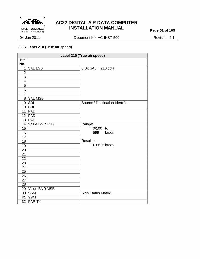
G.3.7 Label 210 (True air speed)
Label 210 (True air speed)
Bit No.
1 SAL LSB 8 Bit SAL = 210 octal
2
3
4
5
6
7
8 SAL MSB
9 SDI Source / Destination Identifier
10 SDI
11 PAD
12 PAD
13 PAD
14 Value BNR LSB Range: 0/100 to 599 knots
Resolution: 0.0625 knots
15
16
17
18
19
20
21
22
23
24
25
26
27
28
29 Value BNR MSB
30 SSM Sign Status Matrix
31 SSM
32 PARITY

REVUE THOMMEN AG CH-4437 Waldenburg
AC32 DIGITAL AIR DATA COMPUTER INSTALLATION MANUAL
Page 53 of 105
04-Jan-2011 Document No. AC-INST-500 Revision 2.1
G.3.8 Label 211 (Total air temperature)
Label 211 (Total air temperature)
Bit No.
1 SAL LSB 8 Bit SAL = 211 octal
2
3
4
5
6
7
8 SAL MSB
9 SDI Source / Destination Identifier
10 SDI
11 PAD Spare Bits
12 PAD
13 PAD
14 PAD
15 PAD
16 PAD
17 PAD
18 Value BNR LSB Range: -60 to +99 degree Celsius
Resolution: 0.25 degree Celsius
19
20
21
22
23
24
25
26
27
28
29 Value BNR MSB
30 SSM Sign Status Matrix
31 SSM
32 PARITY

REVUE THOMMEN AG CH-4437 Waldenburg
AC32 DIGITAL AIR DATA COMPUTER INSTALLATION MANUAL
Page 54 of 105
04-Jan-2011 Document No. AC-INST-500 Revision 2.1
G.3.9 Label 212 (Altitude rate)
Label 212 (Altitude rate)
Bit No.
1 SAL LSB 8 Bit SAL = 212 octal
2
3
4
5
6
7
8 SAL MSB
9 SDI Source / Destination Identifier
10 SDI
11 PAD Spare Bits
12 PAD
13 PAD
14 PAD
15 PAD
16 PAD
17 PAD
18 Value BNR LSB Range: - 32600 to +32600 ft/min.
Resolution: 16 ft/min.
19
20
21
22
23
24
25
26
27
28
29 Value BNR MSB
30 SSM Sign Status Matrix
31 SSM
32 PARITY

REVUE THOMMEN AG CH-4437 Waldenburg
AC32 DIGITAL AIR DATA COMPUTER INSTALLATION MANUAL
Page 55 of 105
04-Jan-2011 Document No. AC-INST-500 Revision 2.1
G.3.10 Label 213 (Static air temperature)
Label 213 (Static air temperature)
Bit No.
1 SAL LSB 8 Bit SAL = 213 octal
2
3
4
5
6
7
8 SAL MSB
9 SDI Source / Destination Identifier
10 SDI
11 PAD Spare Bits
12 PAD
13 PAD
14 PAD
15 PAD
16 PAD
17 PAD
18 Value BNR LSB Range: -99 to +60 degree Celsius
Resolution: 0.25 degree Celsius
19
20
21
22
23
24
25
26
27
28
29 Value BNR MSB
30 SSM Sign Status Matrix
31 SSM
32 PARITY

REVUE THOMMEN AG CH-4437 Waldenburg
AC32 DIGITAL AIR DATA COMPUTER INSTALLATION MANUAL
Page 56 of 105
04-Jan-2011 Document No. AC-INST-500 Revision 2.1
G.3.11 Label 215 (Impact pressure)
Label 215 (Impact pressure)
Bit No.
1 SAL LSB 8 Bit SAL = 215 octal
2
3
4
5
6
7
8 SAL MSB
9 SDI Source / Destination Identifier
10 SDI
11 PAD Spare Bits
12 PAD
13 PAD
14 PAD
15 Value BNR LSB Range: 0 to 372.5 mbar
Resolution: 0.03125 mbar
16
17
18
19
20
21
22
23
24
25
26
27
28
29 Value BNR MSB
30 SSM Sign Status Matrix
31 SSM
32 PARITY

REVUE THOMMEN AG CH-4437 Waldenburg
AC32 DIGITAL AIR DATA COMPUTER INSTALLATION MANUAL
Page 57 of 105
04-Jan-2011 Document No. AC-INST-500 Revision 2.1
G.3.12 Label 217 (Indicated static pressure)
Label 217 (Indicated Static Pressure)
Bit No.
1 Label LSB 8 Bit SAL = 217 octal
2
3
4
5
6
7
8 Label MSB
9 SDI Source / Destination Identifier
10 SDI
11 PAD Spare
12 PAD
13 Value BNR LSB Binary value in the range of 0 inHg +64 inHg Resolution: 0. 0009765 inHg
14
15
16
17
18
19
20
21
22
23
24
25
26
27
28 Value BNR MSB
29 Sign Bit 0 = positive, 1 = negative Number
30 SSM Sign Status Matrix
31 SSM
32 PARITY

REVUE THOMMEN AG CH-4437 Waldenburg
AC32 DIGITAL AIR DATA COMPUTER INSTALLATION MANUAL
Page 58 of 105
04-Jan-2011 Document No. AC-INST-500 Revision 2.1
G.3.13 Label 234 (Baro correction mbar #1)
Label 234 (Baro correction mbar #1)
Bit No.
1 SAL LSB 8 Bit SAL = 234 octal
2
3
4
5
6
7
8 SAL MSB
9 SDI Source / Destination Identifier
10 SDI
11 Value BCD LSB Range: 700 to 1050 mbar
Resolution: 0.1 mbar
12
13
14
15
16
17
18
19
20
21
22
23
24
25
26
27
28
29 Value BCD MSB
30 SSM Value is in BCD Format so SSM indicates if value is positive or negative: SSM_PLUS = 0 SSM_MINUS = 3
31 SSM
32 PARITY

REVUE THOMMEN AG CH-4437 Waldenburg
AC32 DIGITAL AIR DATA COMPUTER INSTALLATION MANUAL
Page 59 of 105
04-Jan-2011 Document No. AC-INST-500 Revision 2.1
G.3.14 Label 235 (Baro correction inHg #1)
Label 235 (Baro correction inHg #1)
Bit No.
1 SAL LSB 8 Bit SAL = 235 octal
2
3
4
5
6
7
8 SAL MSB
9 SDI Source / Destination Identifier
10 SDI
11 Value BCD LSB Range: 20.67 to 31.00 inHg
Resolution: 0.001 inHg
12
13
14
15
16
17
18
19
20
21
22
23
24
25
26
27
28
29 Value BCD MSB
30 SSM Value is in BCD Format so SSM indicates if value is positive or negative: SSM_PLUS = 0 SSM_MINUS = 3
31 SSM
32 PARITY

REVUE THOMMEN AG CH-4437 Waldenburg
AC32 DIGITAL AIR DATA COMPUTER INSTALLATION MANUAL
Page 60 of 105
04-Jan-2011 Document No. AC-INST-500 Revision 2.1
G.3.15 Label 236 (Baro correction mbar #2)
Label 236 (Baro correction mbar #2)
Bit No.
1 SAL LSB 8 Bit SAL = 236 octal
2
3
4
5
6
7
8 SAL MSB
9 SDI Source / Destination Identifier
10 SDI
11 Value BCD LSB Range: 700 to 1050 mbar
Resolution: 0.1 mbar
12
13
14
15
16
17
18
19
20
21
22
23
24
25
26
27
28
29 Value BCD MSB
30 SSM Value is in BCD Format so SSM indicates if value is positive or negative: SSM_PLUS = 0 SSM_MINUS = 3
31 SSM
32 PARITY

REVUE THOMMEN AG CH-4437 Waldenburg
AC32 DIGITAL AIR DATA COMPUTER INSTALLATION MANUAL
Page 61 of 105
04-Jan-2011 Document No. AC-INST-500 Revision 2.1
G.3.16 Label 237 (Baro correction inHg #2)
Label 237 (Baro correction inHg #2)
Bit No.
1 SAL LSB 8 Bit SAL = 237 octal
2
3
4
5
6
7
8 SAL MSB
9 SDI Source / Destination Identifier
10 SDI
11 Value BCD LSB Range: 20.67 to 31.00 inHg
Resolution: 0.001 inHg
12
13
14
15
16
17
18
19
20
21
22
23
24
25
26
27
28
29 Value BCD MSB
30 SSM Value is in BCD Format so SSM indicates if value is positive or negative: SSM_PLUS = 0 SSM_MINUS = 3
31 SSM
32 PARITY

REVUE THOMMEN AG CH-4437 Waldenburg
AC32 DIGITAL AIR DATA COMPUTER INSTALLATION MANUAL
Page 62 of 105
04-Jan-2011 Document No. AC-INST-500 Revision 2.1
G.3.17 Label 242 (Total pressure)
Label 242 (Total pressure)
Bit No.
1 SAL LSB 8 Bit SAL = 242 octal
2
3
4
5
6
7
8 SAL MSB
9 SDI Source / Destination Identifier
10 SDI
11 PAD
12 PAD
13 Value BNR LSB Range: 25 to 2048 mbar
Resolution: 0.03125 mbar
14
15
16
17
18
19
20
21
22
23
24
25
26
27
28
29 Value BNR MSB
30 SSM Sign Status Matrix
31 SSM
32 PARITY

REVUE THOMMEN AG CH-4437 Waldenburg
AC32 DIGITAL AIR DATA COMPUTER INSTALLATION MANUAL
Page 63 of 105
04-Jan-2011 Document No. AC-INST-500 Revision 2.1
G.3.18 Label 270 (Discrete word #1)
Label 270 (Discrete word #1) Logic according to ARINC standard Logical state for listed SW versions1)
Bit No.
1 SAL LSB 8 Bit SAL = 270 octal
2
3
4
5
6
7
8 SAL MSB
9 SDI Source / Destination Identifier
10 SDI
11 Icing Detector 1 = ON, 0 = OFF not available
12 Pitot Probe Heat 1 = ON, 0 = OFF not available
13 ADS Computer Status (WFVOUTS Status)
1 = FAIL 0 = GOOD
1=GOOD 0=FAIL
14 PITOT / STATIC Probe Heat 1 = ON, 0 = OFF not available
15 Static Source Heat 1 = ON, 0 = OFF not available
16 TAT Probe Heat 1 = ON, 0 = OFF
17 Left Side Angle Of Attack Sensor Heat
1 = ON, 0 = OFF not available
18 Right Side Angle Of Attack Sensor Heat
1 = ON, 0 = OFF not available
19 VMO/MMO Overspeed Warning 1 = ON (WARN), 0 = OFF (NOT WARN)
20 Primary Angle Of Attack Input 1 = FAIL, 0 = GOOD not available
21 Angle Of Attack Average 1 = YES, 0 = NO not available
22 VMO Alternate No. 1 1 = YES, 0 = NO not available
23 VMO Alternate No. 2 1 = YES, 0 = NO not available
24 VMO Alternate No. 3 1 = YES, 0 = NO not available
25 VMO Alternate No. 4 1 = YES, 0 = NO not available
26 SSEC Alternate 1 = YES, 0 = NO
27 Angle Of Attack Alternate Correction
1 = YES, 0 = NO not available
28 Baro Correction Port “A” 1 = YES, 0 = NO not available
29 Zero Mach SSEC 1 = YES, 0 = NO (spare)
30 SSM
31 SSM
32 PARITY
Note 1: Only the following SW versions have the logic (1=GOOD, 0=FAIL) for ADS Computer Status: 1.53, 1.54, 2.00, 2.10, 2.11, 2.20, 2.30, 2.40.

REVUE THOMMEN AG CH-4437 Waldenburg
AC32 DIGITAL AIR DATA COMPUTER INSTALLATION MANUAL
Page 64 of 105
04-Jan-2011 Document No. AC-INST-500 Revision 2.1
G.3.19 Label 271 (Discrete word #2)
Label 271 (Discrete word #2)
Bit No.
provision, not used in ADU32
1 SAL LSB 8 Bit SAL = 271 octal
2
3
4
5
6
7
8 SAL MSB
9 SDI Source / Destination Identifier
10 SDI
11 Zero Angle Of Attack 1 = YES, 0 = NO
12 Angle Of Attack Sensor Status 1 = FAIL, 0 = GOOD
13
14
15
16
17
18
19
20
21
22
23
24
25
26
27
28
29
30 SSM
31 SSM
32 PARITY

REVUE THOMMEN AG CH-4437 Waldenburg
AC32 DIGITAL AIR DATA COMPUTER INSTALLATION MANUAL
Page 65 of 105
04-Jan-2011 Document No. AC-INST-500 Revision 2.1
G.3.20 Label 320 (Magnetic Heading)
Label 320 (Magnetic Heading)
Bit No.
1 SAL LSB 8 Bit SAL = 320 octal
2
3
4
5
6
7
8 SAL MSB
9 SDI Source / Destination Identifier
10 SDI
11 Range / Layout: n/a
12
13
14
15
16
17
18
19
20
21
22
23
24
25
26
27
28
29
30 SSM Sign Status Matrix
31 SSM
32 PARITY

REVUE THOMMEN AG CH-4437 Waldenburg
AC32 DIGITAL AIR DATA COMPUTER INSTALLATION MANUAL
Page 66 of 105
04-Jan-2011 Document No. AC-INST-500 Revision 2.1
G.3.21 Label 350 (Maintenance word #1)
Label 350 (Maintenance word #1)
Bit No.
1 SAL LSB 8 Bit SAL = 350 octal This Label transmits Information about alerter and display settings needed to provide synchronisation of two peers. It should not be used on AC32.
2
3
4
5
6
7
8 SAL MSB
9 SDI Source / Destination Identifier
10 SDI
11 Value BNR LSB Range: -1000 to +53000 feet
Resolution: 1 foot
12
13
14
15
16
17
18
19
20
21
22
23
24
25
26 Value BNR MSB
27 Value Sign Bit 0= positive value, 1 = negative value
28 Alerter State Indicates if Alerter is switched off(0) or on (1)
29 Altitude Display state Indicates if the Altitude is displayed in Feet (0) or in Meter (1)
30 Baro Display state Indicates if the Baro setting is displayed in mbar (0) or in inHg(1)
31 Push To Reset state Indicates a “Push To Reset” Baro setting. Since the format of the Baro correction labels (234-237) has not the required precision to detect a reset to 1013.25 mbar.
32 PARITY

REVUE THOMMEN AG CH-4437 Waldenburg
AC32 DIGITAL AIR DATA COMPUTER INSTALLATION MANUAL
Page 67 of 105
04-Jan-2011 Document No. AC-INST-500 Revision 2.1
G.3.22 Label 351 (Maintenance word #2)
Label 351 (Maintenance word #2)
Bit No.
1 SAL LSB 8 Bit SAL = 351 octal
2
3
4
5
6
7
8 SAL MSB
9 SDI Source / Destination Identifier
10 SDI
11
12
13
14
15
16
17
18
19
20
21
22
23
24
25
26
27
28
29
30
31
32 PARITY
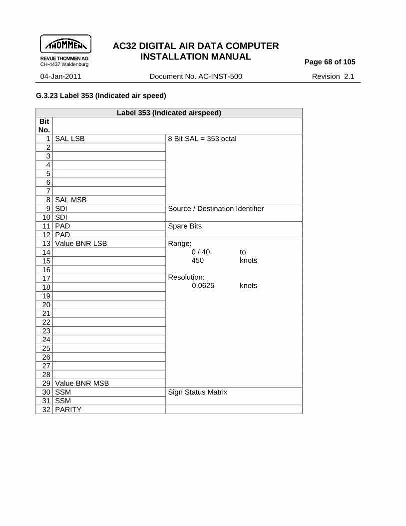
REVUE THOMMEN AG CH-4437 Waldenburg
AC32 DIGITAL AIR DATA COMPUTER INSTALLATION MANUAL
Page 68 of 105
04-Jan-2011 Document No. AC-INST-500 Revision 2.1
G.3.23 Label 353 (Indicated air speed)
Label 353 (Indicated airspeed)
Bit No.
1 SAL LSB 8 Bit SAL = 353 octal
2
3
4
5
6
7
8 SAL MSB
9 SDI Source / Destination Identifier
10 SDI
11 PAD Spare Bits
12 PAD
13 Value BNR LSB Range: 0 / 40 to 450 knots
Resolution: 0.0625 knots
14
15
16
17
18
19
20
21
22
23
24
25
26
27
28
29 Value BNR MSB
30 SSM Sign Status Matrix
31 SSM
32 PARITY
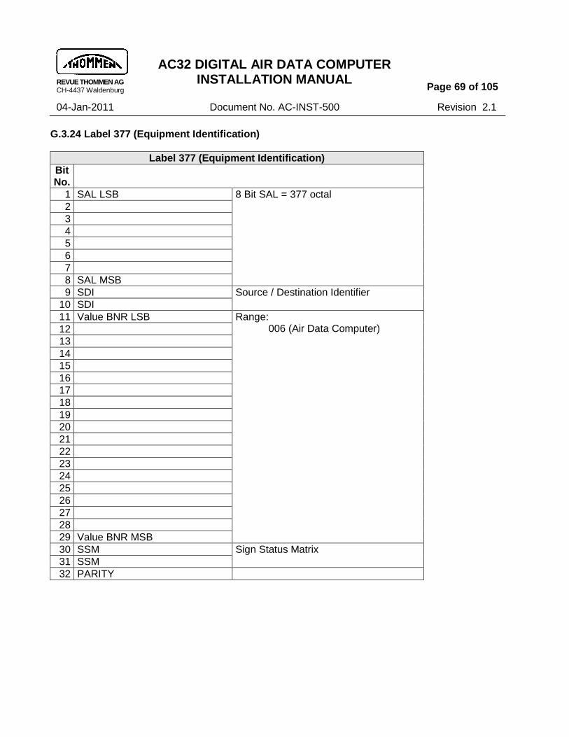
REVUE THOMMEN AG CH-4437 Waldenburg
AC32 DIGITAL AIR DATA COMPUTER INSTALLATION MANUAL
Page 69 of 105
04-Jan-2011 Document No. AC-INST-500 Revision 2.1
G.3.24 Label 377 (Equipment Identification)
Label 377 (Equipment Identification)
Bit No.
1 SAL LSB 8 Bit SAL = 377 octal
2
3
4
5
6
7
8 SAL MSB
9 SDI Source / Destination Identifier
10 SDI
11 Value BNR LSB Range: 006 (Air Data Computer)
12
13
14
15
16
17
18
19
20
21
22
23
24
25
26
27
28
29 Value BNR MSB
30 SSM Sign Status Matrix
31 SSM
32 PARITY

REVUE THOMMEN AG CH-4437 Waldenburg
AC32 DIGITAL AIR DATA COMPUTER INSTALLATION MANUAL
Page 70 of 105
04-Jan-2011 Document No. AC-INST-500 Revision 2.1
H. Discrete I/O‟s
H.1 Discrete Inputs
Six (6) discrete inputs (0-5) are available. The use and logic of the discrete are parametrical.
NOTE: For use and assignment refer to the individual execution of your type in the AC32.() Technical Checklist (TCL).
Voltage level 28 VDC power supply
„High‟ >= 18.5 … <= 36 VDC acc. to ARINC 706-4 section 4.11.4
„Low‟ >= 0 … <= 3.5 VDC
No. Signal (default) Description Activation/Logic (default)
0 TEST Performs a restart of the instrument high = Normal low = activate BIT
1 Discrete input 1 Refer to TCL --
2 Discrete input 2 Refer to TCL --
3 Discrete input 3 Refer to TCL --
4 Discrete input 4 Refer to TCL --
5 ICAO Strobe Detects Strobe signal high = Code off low = Code on
Table 14: Discrete Inputs
NOTE: Discretes “SSEC Selection”, “Zero MACH SSEC“ and “TAT Heat” are also indicated by the ARINC 429 data label 270, Discrete Word #1.

REVUE THOMMEN AG CH-4437 Waldenburg
AC32 DIGITAL AIR DATA COMPUTER INSTALLATION MANUAL
Page 71 of 105
04-Jan-2011 Document No. AC-INST-500 Revision 2.1
H.2 Discrete Outputs
Three (3) discrete outputs( 1-3) are available. The use and logic of the discrete is parametric.
NOTE: For use refer to the individual execution of your type in a Appendix II Digital Air Data Computer Execution.
Voltage level 28 VDC power supply
„High‟ >= 18.5 … <= 36 VDC acc. to ARINC 706-4 section 4.11.4
„Low‟ >= 0 … <= 3.5 VDC
No. Signal (default) Description Activation Electrical
0 Warning Flag Valid Output Signal WFVOUTS
indicates proper operation and no critical failure
high = Normal low = Failure condition
28 VDC / max. 14mA
1 Discrete output 1 Refer to TCL -- Open drain, max. 1 A
2 Discrete output 2 Refer to TCL -- Open drain, max. 1 A
3 Discrete output 3 Refer to TCL -- Open drain, max. 1 A
Table 15: Discrete Outputs
I. ICAO Encoded Altitude Output
The Digital Air Data Computer has an encoded altitude output (in feet) for automatic altitude reporting in accordance with TSO-C88a. Reported Altitude is always relative to standard pressure (29.9213 inHg or 1013.25 mbar). NOTE: To activate, the ICAO strobe discrete input no. 5 must be grounded.
J. RS-232 Serial Interface
The flight instrument has a RS-232 interface for maintenance and calibration purposes only. This interface is not accessible for normal operation in the aircraft.
NOTE: The pins for RS-232 TxD and RxD shall be jumpered in the connector on the aircraft side to avoid inadvertent interferences!

REVUE THOMMEN AG CH-4437 Waldenburg
AC32 DIGITAL AIR DATA COMPUTER INSTALLATION MANUAL
Page 72 of 105
04-Jan-2011 Document No. AC-INST-500 Revision 2.1
SECTION V
1. Trouble shooting
The table below shows the general troubleshooting information to assist in locating and correcting any malfunctions with the AC32 Digital Air Data Computer. Procedure:
Malfunction Probable cause Remedy
Digital I/O fails I/O signal out of tolerance
electronic module failure
make sure the I/O signal
repair electronic module
Warning Flag Valid Signal is Low
Failure Test the equipment and installation
TAT/OAT output out of range
Temperature probe not connected correctly
Make sure the probe or replacement resistor is connected
Encoding output is not working
Discrete input no. 5 (ICAO strobe) is not grounded / Encoder is off
Ensure ground connection
Check Encoder function
Table 16: Trouble Shooting Procedures
NOTE: For any malfunction of the equipment not listed in the table above, Manufacturer can
be contacted for assisting in the trouble shooting. Check the equipment using the THOMMEN RS-232 monitoring SW. Read out the failure
memory (BIT history) to analyse failures.

REVUE THOMMEN AG CH-4437 Waldenburg
AC32 DIGITAL AIR DATA COMPUTER INSTALLATION MANUAL
Page 73 of 105
04-Jan-2011 Document No. AC-INST-500 Revision 2.1
2. Maintenance
The flight equipment can be completely repairable at depot level, down to the module or subassembly equipment. The maintenance task time, which includes preparation (setup) for test, recognition (validation) of a fault, isolation of cause of the fault, repair of the fault and preliminary checkout shall not exceed 2 hours repair time for any single failure in an instrument. The Maintenance of the AC32 Digital Air Data Computer must be performed by the manufacturer representative or certified staff. ADAC32 Maintenance manual describes software installation, the required maintenance files and the performance range of the instrument. The requirements for software maintenance of the instruments are RS-232 Serial Data cable, computer with Microsoft Windows and the ADAC32 CDROM with maintenance Software.
A. Recalibration Interval
The AC32 Digital Air Data Computer has the following recalibration intervals:
Sensor Type recalibration interval
High-end transducers On Condition

REVUE THOMMEN AG CH-4437 Waldenburg
AC32 DIGITAL AIR DATA COMPUTER INSTALLATION MANUAL
Page 74 of 105
04-Jan-2011 Document No. AC-INST-500 Revision 2.1
APPENDICES
Appendix I
Failure Codes
FC Description Start Up / Initiated
Continuous ARINC Failure Class
001
Program checksum Error X - OFF
- X FW 1
002 Parameter checksum Error X - OFF
003 Calibration checksum Error X - FW 1
005 RAM Test Error X - OFF
- X FW 1
006 CPU Test Error X - OFF
007 Watchdog Test Error X - OFF
010 ARINC 429 Error X - OFF
- X OFF
012 I2C bus Error X - OFF
- X FW 1
013 Configuration Error X - OFF
014 I/O Expander Error X - OFF
021 3.3V Voltage Failure - X FW 1
022 +5.0V Voltage Failure - X FW 1
023 -5.0V Voltage Failure - X FW 1
024 +15.0V Voltage Failure - X OFF
025 -15.0V Voltage Failure - X OFF
026 28.0V Voltage Failure - X FW 1
027 +2.5V reference Voltage Failure - X FW 1
028 Power Backup System Failure X - -
037 Static Frequency Measurement Device Error X - FW 37
038 Pitot Frequency Measurement Device Error X - FW 38
039 TAT A/D-C Error X - FW 39
040 Static A/D-C Failure - X FW 37
041 Pitot A/D-C Failure - X FW 38
042 Static Pressure Range Failure - X FW 37
043 Pitot Pressure Range Failure - X FW 38
044 Baro Corrected Altitude Out of Range Failure - X FW 44
045 IAS Out of Range Failure - X FW 45
046 CAS Out of Range Failure - X FW 46
047 TAS Out of Range Failure - X FW 47
049 VMO Out of Range Failure - X FW 49
050 Mach No Out of Range Failure - X FW 50

REVUE THOMMEN AG CH-4437 Waldenburg
AC32 DIGITAL AIR DATA COMPUTER INSTALLATION MANUAL
Page 75 of 105
04-Jan-2011 Document No. AC-INST-500 Revision 2.1
FC Description Start Up / Initiated
Continuous ARINC Failure Class
051 Altitude Rate Out of Range Failure - X FW 51
052 TAT Out of Range Failure - X FW 39
053 SAT Out of Range Failure - X FW 53
055 Static Sensor Temperature Out of Range Failure - X FW 37
056 Pitot Sensor Temperature Out of Range Failure - X FW 38
057 Static Sensor Temperature Diode Voltage Failure X X FW 37
058 Pitot Sensor Temperature Diode Voltage Failure X X FW 38
059 Null Drift Test and Failure X - FW 59
065 Pressure Altitude Out of Range Failure X FW 65
070 WFVOUTS Failure - X -
071 ICAO Failure - X -
074 Instrument disabled by discrete input - - FW 1
080 No Initialisation Failure X - OFF
255 Unknown Error Code failure N/A N/A FW 1
ARINC failure class definition If a failure occures at following ARINC 429 labels the Failure Warning shall be indicated in the SSM.
SAL 102 203 204 205 206 207 210 211 212 213 215 217 242 270 353 377
Sele
cte
d
Altitude
Pre
ssure
altitude
Baro
corr
.
altitude #
1
Ma
ch
num
ber
Com
pute
d
airspeed
Ma
x. A
llow
.
Airspeed
Tru
e
airspeed
To
tal air
tem
p
Altitude
Rate
Sta
tic a
ir
tem
p
Imp
act
Pre
ssure
Sta
tic
Pre
ssure
To
tal
Pre
ssure
Dis
cre
te
Word
#1
Indic
ate
d
airspeed
Equip
me
nt
Identificatio
n
FW 1 FW FW FW FW FW FW FW FW FW FW FW FW FW FW FW FW
FW 37 - FW FW FW FW FW FW FW FW FW FW FW - - FW -
FW 38 - - - FW FW - FW FW - FW FW - FW - FW -
FW 39 - - - - - - FW FW - FW - - - - - -
FW 44 - FW FW - - FW - - FW - - - - - - -
FW 45 - - - FW - - FW FW - FW - - - - FW -
FW 46 - - - - FW - - - - - - - - - - -
FW 47 - - - - - - FW - - - - - - - - -
FW 49 - - FW - - FW - - - - - - - - - -
FW 50 - - - FW - - FW FW - FW - - - - - -
FW 51 - - - - - - - - FW - - - - - - -
FW 53 - - - - - - FW - - FW - - - - - -
FW 59 - FW FW FW FW FW FW FW FW FW FW - FW - FW -
FW 65 - FW FW - - *** - - FW - - - - - - -
Legend: FW set SSM flag to failure - no SSM flag setting *** depending on VMO calibration

REVUE THOMMEN AG CH-4437 Waldenburg
AC32 DIGITAL AIR DATA COMPUTER INSTALLATION MANUAL
Page 76 of 105
04-Jan-2011 Document No. AC-INST-500 Revision 2.1
BIT-Matrix The failure reaction is defined in the BIT Matrix:
FC
Cri
tica
l E
rro
r
No
n C
riti
cal
Err
or
Sto
p
Op
era
tio
n
ICA
O O
ff
Warn
ing
Fla
g
ind
icati
on
Sto
re F
ailu
re
No
n
Reco
ve
rab
le
Dis
ab
le
AR
INC
429 IF
001 CI SO CO WF SF NR
002 CI SO CO WF SF NR
003 CI SO CO WF SF NR
005 CI SO CO WF SF NR
006 CI SO CO WF SF NR
007 EI WF SF NR
010 EI WF SF NR DA
012 CI SO CO WF NR
013 CI SO CO WF SF NR
014 CI SO CO WF SF NR
021 CI SO CO WF NR
022 CI SO CO WF SF NR
023 CI SO CO WF SF NR
024 CI SO CO WF SF NR DA
025 CI SO CO WF SF NR DA
026 CI SO CO WF SF NR
027 CI SO CO WF SF NR
028 EI WF NR
037 CI SO CO WF SF NR
038 EI WF SF
039 EI WF SF
040 CI SO CO WF SF
041 EI WF SF
042 EI WF SF
043 EI WF SF
044 EI WF SF
045 EI WF SF
046 EI WF SF
047 EI WF SF
049 EI WF SF
050 EI WF SF
051 EI WF SF
052 EI WF SF
053 EI WF SF
055 CI SO CO WF SF NR
056 EI WF SF
057 CI SO CO WF SF NR

REVUE THOMMEN AG CH-4437 Waldenburg
AC32 DIGITAL AIR DATA COMPUTER INSTALLATION MANUAL
Page 77 of 105
04-Jan-2011 Document No. AC-INST-500 Revision 2.1
FC
Cri
tica
l E
rro
r
No
n C
riti
cal
Err
or
Sto
p
Op
era
tio
n
ICA
O O
ff
Warn
ing
Fla
g
ind
icati
on
Sto
re F
ailu
re
No
n
Reco
ve
rab
le
Dis
ab
le
AR
INC
429 IF
058 EI WF SF
059 CI SO CO WF SF NR
065 EI CO WF SF
070 SF
071 EI CO WF SF NR
074 CI SO CO WF SF
080 CI SO CO WF NR
255 CI SO CO WF SF
Note: The following abbreviations are used for the failure attributes. CI : Critical Error EI : Non Critical Error SO : Stop Operation CO : ICAO Off WF : Warning Flag indication (WFVOUTS) SF : Store Failure NR : Non Recoverable DA : Disable ARINC 429 Interface

REVUE THOMMEN AG CH-4437 Waldenburg
AC32 DIGITAL AIR DATA COMPUTER INSTALLATION MANUAL
Page 78 of 105
04-Jan-2011 Document No. AC-INST-500 Revision 2.1
Appendix II
Altimeter Calibration Table
Altitude [Feet]
Tolerance acc. to TSO-C10b ± [Feet]
Tolerance acc. to RVSM requirements ± [Feet] 2)
(Baro setting 1‟013 mbar)
@25 °C @ -30/+71°C 1) @25 °C @ -30/+71°C 1)
-1‟000 0 500 1'000 1'500 2„000 3„000 4„000 6„000 8„000 10'000 12'000 14„000 16'000 18„000 20'000 22„000 25'000
20 20 20 20 25
30 30 35 40 60
80 90 100 110 120
130 140 155
-- 40 -- -- --
-- -- -- 60 --
-- 90 -- --
120
-- --
155
10 10 10 10 10
10 10 10 10 10
10 10 10 10 10
15 15 15
-- 10 -- -- --
-- -- -- 10 --
-- 10 -- -- 10
-- -- 15
29'000 30'000 32'500 35'000 37'500 40'000 41'000
-- 180 --
205 --
230 --
-- -- --
205 -- -- --
20 20 25 25 30 30 30
-- -- -- 25 -- -- --
45„000 50'000 53„000
255 280
(295)
-- 280 --
40 45 50
-- 45 --
NOTE: 1) allowable change from room temperature scale error test indication 2) SSEC data are applied automatically.
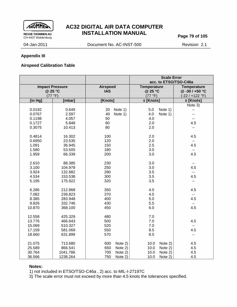
REVUE THOMMEN AG CH-4437 Waldenburg
AC32 DIGITAL AIR DATA COMPUTER INSTALLATION MANUAL
Page 79 of 105
04-Jan-2011 Document No. AC-INST-500 Revision 2.1
Appendix III
Airspeed Calibration Table
Scale Error
acc. to ETSO/TSO-C46a
Impact Pressure @ 25 °C (77 °F)
Airspeed IAS
Temperature @ 25 °C (77 °F)
Temperature @ -30 / +50 °C (-22 / +122 °F)
[in Hg] [mbar] [Knots] ± [Knots] ± [Knots]
Note 3) 0.0192 0.649 20 Note 1) 5.0 Note 1) -- 0.0767 2.597 40 Note 1) 4.0 Note 1) -- 0.1198 4.057 50 4.0 -- 0.1727 5.848 60 2.0 4.5 0.3075 10.413 80 2.0 --
0.4814 16.302 100 2.0 4.5 0.6950 23.535 120 2.0 -- 1.091 36.945 150 2.5 4.5 1.580 53.505 180 3.0 -- 1.959 66.339 200 3.0 4.5
2.610 88.385 230 3.0 -- 3.100 104.978 250 3.0 4.5 3.924 132.882 280 3.5 -- 4.534 153.538 300 3.5 4.5 5.195 175.922 320 3.5 --
6.286 212.868 350 4.0 4.5 7.082 239.823 370 4.5 -- 8.385 283.948 400 5.0 4.5 9.826 332.746 430 5.5 --
10.870 368.100 450 6.0 4.5
12.558 425.329 480 7.0 13.776 466.643 500 7.0 4.5 15.069 510.327 520 7.0 -- 17.159 581.069 550 8.5 4.5 18.660 631.899 570 8.5 --
21.075 713.680 600 Note 2) 10.0 Note 2) 4.5 25.589 866.541 650 Note 2) 10.0 Note 2) 4.5 30.764 1041.786 700 Note 2) 10.0 Note 2) 4.5 36.566 1238.264 750 Note 2) 10.0 Note 2) 4.5
Notes: 1) not included in ETSO/TSO-C46a , 2) acc. to MIL-I-27197C 3) The scale error must not exceed by more than 4.5 knots the tolerances specified.

REVUE THOMMEN AG CH-4437 Waldenburg
AC32 DIGITAL AIR DATA COMPUTER INSTALLATION MANUAL
Page 80 of 105
04-Jan-2011 Document No. AC-INST-500 Revision 2.1
Appendix IV
MACH Number Calibration Table
MACHi
(indicated MACH number)
Tolerances acc. to SAE AS8002 Revision A ± MACH
@ Altitude 0 feet @ 25 °C (77 °F) @ -20 / +71°C (-4 / +160 °F)
0.200 0.300 0.400 0.500 0.600
0.012 0.012 0.012 0.010 0.0075
0.016 0.016 0.016 0.014 0.010
@ Altitude 10„000 feet @ 25 °C (77 °F) @ -20 / +71°C (-4 / +160 °F)
0.400 0.500 0.600 0.700
0.012 0.010 0.0075 0.005
0.016 0.014 0.010 0.007
@ Altitude 20„000 feet @ 25 °C (77 °F) @ -20 / +71°C (-4 / +160 °F)
0.400 0.500 0.600 0.700
0.012 0.010 0.0075 0.005
0.016 0.014 0.010 0.007
@ Altitude 30„000 feet @ 25 °C (77 °F) @ -20 / +71°C (-4 / +160 °F)
0.600 0.700 0.800 0.900 0.950
0.0075 0.005 0.005 0.005 0.0075
0.010 0.007 0.007 0.007 0.010
MACH Calculated Tolerances acc. to ETSO/TSO-C46a/SAE AS418A ± MACH
@ Altitude 40„000 feet @ 25 °C (77 °F) @ -20 / +71°C (-4 / +160 °F)
0.700 0.800 0.900 0.950
0.013 0.013 0.013 0.013
0.027 0.026 0.025 0.025
@ Altitude 50„000 feet @ 25 °C (77 °F) @ -20 / +71°C (-4 / +160 °F)
0.700 0.800 0.900 1.000
0.016 0.016 0.015 0.015
0.034 0.032 0.031 0.030

REVUE THOMMEN AG CH-4437 Waldenburg
AC32 DIGITAL AIR DATA COMPUTER INSTALLATION MANUAL
Page 81 of 105
04-Jan-2011 Document No. AC-INST-500 Revision 2.1
MACH Tolerances (equipment specification) ± MACH
@ Altitude 60„000 feet @ 25 °C (77 °F) @ -20 / +71°C (-4 / +160 °F)
0.900 1.000 1.200
0.020 0.020 0.200
0.030 0.030 0.030
@ Altitude 70„000 feet @ 25 °C (77 °F) @ -20 / +71°C (-4 / +160 °F)
0.900 1.000 1.200
0.025 0.025 0.025
0.035 0.035 0.035
@ Altitude 80„000 feet @ 25 °C (77 °F) @ -20 / +71°C (-4 / +160 °F)
0.900 1.000 1.200
0.030 0.030 0.030
0.040 0.040 0.040

REVUE THOMMEN AG CH-4437 Waldenburg
AC32 DIGITAL AIR DATA COMPUTER INSTALLATION MANUAL
Page 82 of 105
04-Jan-2011 Document No. AC-INST-500 Revision 2.1
Appendix V
Total Air Temperature (TAT) / Outside Air Temperature (OAT) Calibration Table
TTi Resistance Pt 500 acc. to ARINC 706-4
Indicated Total Air Temperature °C
Ohm
-60 381.64
-30 441.16
0 500.00
30 558.21 60 615.79
99 689.72
TAT/OAT Calibration Table: Resistance Pt 500
TTi Resistance Pt 100 acc. to EN 60751
Indicated Total Air Temperature °C
Ohm
-60 76.328
-30 88.222
0 100.000
30 111.673
60 123.242
99 138.126
TAT/OAT Calibration Table: Resistance Pt 100

REVUE THOMMEN AG CH-4437 Waldenburg
AC32 DIGITAL AIR DATA COMPUTER INSTALLATION MANUAL
Page 83 of 105
04-Jan-2011 Document No. AC-INST-500 Revision 2.1
Appendix VI
Equipment Dimensions : Compact Case
Equipment Front and Rear View
NOTE: The dimensions are in millimeters or inches NOTE: Not to scale Pneumatic Pressure Ports
Mechanical Pressure range Over pressure capability
Static Port ”S” (Standard)
1/2“-20UNJF-3B (MS33649-5)
100 … 1050 mbar abs 1500 mbar abs
Static Port ”S” (optional)
9/16“-18UNJF-3B (MS33649-6)
25 … 1100 mbar abs 1500 mbar abs
Pitot Port “P” 7/16“-20UNJF-3B (MS33649-4)
100 … 1500 mbar abs 3000 mbar abs

REVUE THOMMEN AG CH-4437 Waldenburg
AC32 DIGITAL AIR DATA COMPUTER INSTALLATION MANUAL
Page 84 of 105
04-Jan-2011 Document No. AC-INST-500 Revision 2.1
Equipment Side and Top View

REVUE THOMMEN AG CH-4437 Waldenburg
AC32 DIGITAL AIR DATA COMPUTER INSTALLATION MANUAL
Page 85 of 105
04-Jan-2011 Document No. AC-INST-500 Revision 2.1
Appendix VII
Identification Plates
The Identification/Name plates is attached in the equipment case of AC32 Digital Air Data Computer externally. The sample of Identification/Name plates of AC32 Digital Air Data Computer equipment is shown below:
REVUE THOMMEN AG CH-4437 WALDENBURG
DIGITAL AIR DATA COMPUTER CERTIFIED TSO-C88a, TSO-C106 WT 1000 gm (2.20 lbs)
RTCA/DO-160D [D2]BBB[(TB1)(TR)]/[(SL)(SM)]/[(UG)]XWFDFSZZAZZ[YY]M[A3J33]XAA
RTCA/DO-178B LEVEL A CONFIG ID
PART/TYPE NO AC32.10.21.11.AF 5020
SER NO xxxxxxx PWR SUPPLY 28 VDC
RANGES -1'000 … 53'000 FEET
0/40 … 450 KNOTS 0.200 … 950 MACH MFR DATE month / year
SWISS MADE PHONE +41 61 965 22 22 [email protected]
REVUE THOMMEN AG CH-4437 WALDENBURG
HW version 2.00
SW version 2.31
MOD HW 00 01 02 03 04 05 06 07 08 09 10 11 12 13 14 15 16
SW A B C D E F G H I J K L M N P R S
SWISS MADE PHONE +41 61 965 22 22 [email protected]

REVUE THOMMEN AG CH-4437 Waldenburg
AC32 DIGITAL AIR DATA COMPUTER INSTALLATION MANUAL
Page 86 of 105
04-Jan-2011 Document No. AC-INST-500 Revision 2.1
Appendix VIII
Software Version SW 2.10:
The Software (SW) Version 2.10 is applicable for all AC32 Digital Air Data Computer Versions. The features included in SW Version 2.10 are described as follows:
1) ARINC429 functionality
All ARINC429 labels are made available on all channels as independent and independency of Barometric correction ARINC 429 Label 234 and Label 235
All ARINC 429 Labels available with AC32 Digital Air Data Computer are made independent with SW 2.10 Version ( Excluding the ARINC 429 labels 203 for the purpose of ALT comparison Fail function).
ARINC 429 Label 234 and Label 235 are made independent , requiring only one ARINC 429 Label 234 or Label 235 for Barometric correction value.
The following priorities are available on the equipment to receive Barometric values for the barometric correction:
Priority 1 - ARINC 429 LABEL 235 on Rx 1 Channel
Priority 2 - ARINC 429 LABEL 235 on Rx 2 Channel
Priority 3 - ARINC 429 LABEL 234 on Rx 1 Channel
Priority 4 - ARINC 429 LABEL 234 on Rx 2 Channel

REVUE THOMMEN AG CH-4437 Waldenburg
AC32 DIGITAL AIR DATA COMPUTER INSTALLATION MANUAL
Page 87 of 105
04-Jan-2011 Document No. AC-INST-500 Revision 2.1
The following table shows the ARINC 429 Labels available on different ARINC Transmit and Receive Channels:
Label Signal Name I/O Transfer Channel Digital ADC
203 Pressure altitude (1013.25 mbar)
TxD1/TxD2 --
204 Baro corrected altitude #1 TxD1/TxD2 --
220 Baro corrected altitude #2 TxD1/TxD2 --
205 Mach number TxD1/TxD2 --
206 Computed airspeed TxD1/TxD2 --
207 Maximum Allowable Airspeed TxD1/TxD2 --
210 True airspeed TxD1/TxD2 --
211 Total air temperature TxD1/TxD2 --
212 Altitude Rate TxD1/TxD2 --
213 Static air temperature TxD1/TxD2 --
215 Impact Pressure TxD1/TxD2 --
217 Static Pressure TxD1/TxD2 --
234 Baro Correction mb #1 TxD1/TxD2 RxD1/RxD2
235 Baro Correction inHg #1 TxD1/TxD2 RxD1/RxD2
236 Baro Correction mb #2 TxD1/TxD2 RxD1/RxD2
237 Baro Correction inHg #2 TxD1/TxD2 RxD1/RxD2
242 Total Pressure TxD1/TxD2 --
270 Discrete Word #1 TxD1/TxD2 --
271 Discrete Word #2 (provision) -- --
320 Heading TxD1/TxD2 RxD1/RxD2
350 Maintenance Word #1 TxD1/TxD2 RxD1/RxD2
351 Maintenance Word #2 (provision)
-- --
353 Indicated airspeed TxD1/TxD2 --
377 Equipment Identifier TxD1/TxD2 --

REVUE THOMMEN AG CH-4437 Waldenburg
AC32 DIGITAL AIR DATA COMPUTER INSTALLATION MANUAL
Page 88 of 105
04-Jan-2011 Document No. AC-INST-500 Revision 2.1
Source/Destination Identifier function are made available as discrete inputs on AC32 Digital Air Data Computer. It identifies the ARINC 429 source.
Note: SDI Bit status is detected during startup only.
Source/Destination Identifier
SDI pin A SDI pin B ARINC 429 Source
Bit 10 Bit 9 Equipment No.
0 0 0
0 1 1
1 0 2
1 1 3
ARINC 429 Label 320 (Magnetic Heading) and Label 350 (Maintenance Word #1) are made available on AC32 Digital Air Data Computer as forwarded only depending on when activated in the configuration.
Note: ARINC 429 Label 320 is forwarded, when enabled in the configuration. Note: ARINC 429 Label 350 is forwarded, when disabled in the configuration.
Note: For use and assignment refer to the individual execution of instrument type in the AC32
Technical Checklist. Note: Sign Status Matrix
SSM SSM
Bit 31 Bit 30 Equipment Status
0 0 Failure warning
0 1 No computed data
1 0 Functional test
1 1 Normal operation

REVUE THOMMEN AG CH-4437 Waldenburg
AC32 DIGITAL AIR DATA COMPUTER INSTALLATION MANUAL
Page 89 of 105
04-Jan-2011 Document No. AC-INST-500 Revision 2.1
ARINC 429 Label 217 (Static Pressure) is added on AC32 Digital Air Data Computer equipment.
Label 217 (Static Pressure)
Bit No.
1 Label LSB 8 Bit SAL = 217 octal
2
3
4
5
6
7
8 Label MSB
9 SDI Source / Destination Identifier
10 SDI
11 PAD Spare
12 PAD
13 Value BNR LSB Binary value in the range of 0 inHg +64 inHg
Resolution:
0. 0009765 inHg
14
15
16
17
18
19
20
21
22
23
24
25
26
27
28 Value BNR MSB
29 Sign Bit 0 = positive, 1 = negative Number
30 SSM Sign Status Matrix
31 SSM
32 PARITY

REVUE THOMMEN AG CH-4437 Waldenburg
AC32 DIGITAL AIR DATA COMPUTER INSTALLATION MANUAL
Page 90 of 105
04-Jan-2011 Document No. AC-INST-500 Revision 2.1
Appendix IX
Software Version SW 2.11:
Forwarded Standard and Non-Standard ARINC 429 labels
The table below shows the list of ARINC 429 labels which are in the forwarded format. These Standard and Non standard ARINC 429 labels transmit on ARINC channel # 1 and # 2 when it is received either on ARINC channel # 1 or # 2 . When activated for forwarding, the same calculable ARINC 429 labels are disabled by configuration.
Label Condition Action
102 Alerter enabled by configuration transmit own label
102 Alerter disabled by configuration forward received label
104N -- forward received label
161N -- forward received label
207 Label enabled by configuration transmit own label
207N Label disabled by configuration forward received label
210 Label enabled by configuration transmit own label
210N Label disabled by configuration forward received label
244N -- forward received label
271N Label enabled by configuration forward received label
271N Label disabled by configuration forward received label
320 Label enabled by configuration forward received label
350 Label enabled by configuration transmit own label
350 Label disabled by configuration forward received label
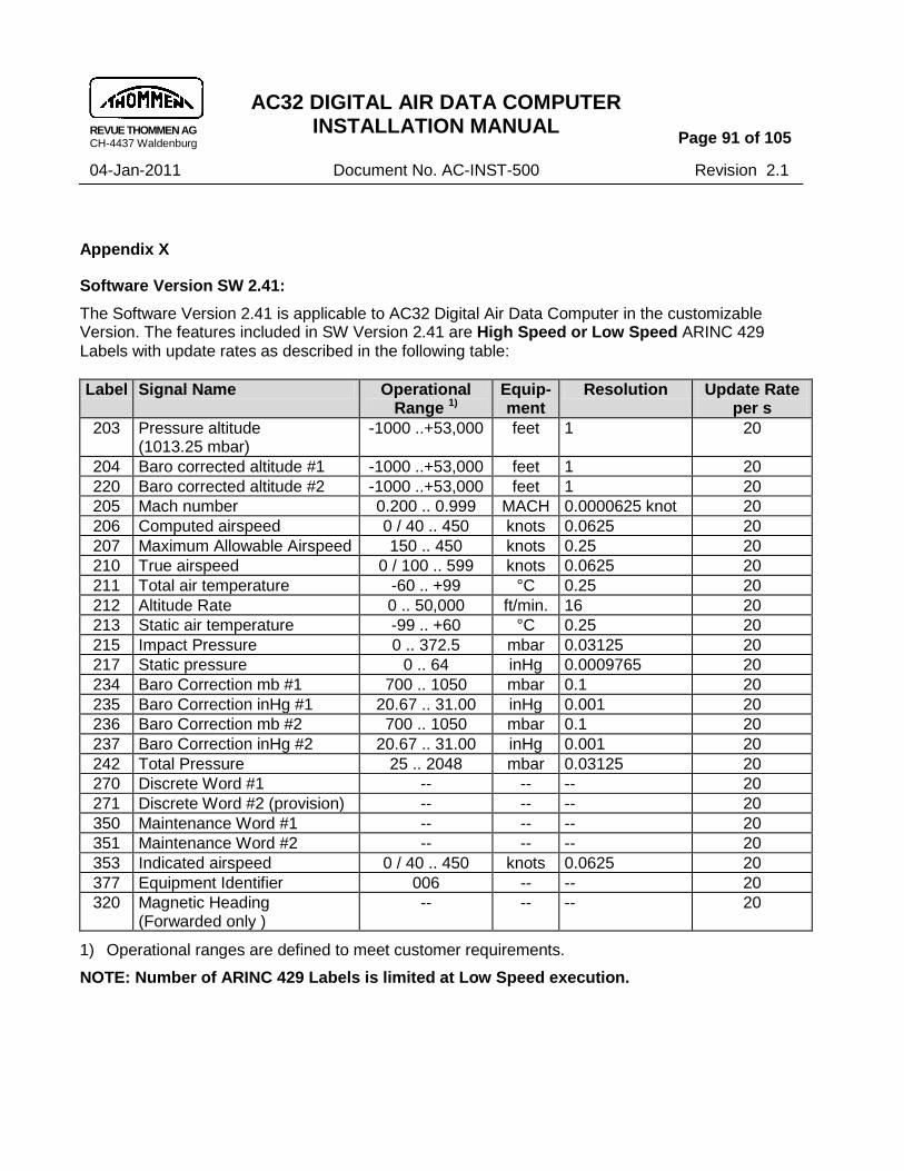
REVUE THOMMEN AG CH-4437 Waldenburg
AC32 DIGITAL AIR DATA COMPUTER INSTALLATION MANUAL
Page 91 of 105
04-Jan-2011 Document No. AC-INST-500 Revision 2.1
Appendix X
Software Version SW 2.41:
The Software Version 2.41 is applicable to AC32 Digital Air Data Computer in the customizable Version. The features included in SW Version 2.41 are High Speed or Low Speed ARINC 429 Labels with update rates as described in the following table:
Label Signal Name Operational Range 1)
Equip-ment
Resolution Update Rate per s
203 Pressure altitude (1013.25 mbar)
-1000 ..+53,000 feet 1 20
204 Baro corrected altitude #1 -1000 ..+53,000 feet 1 20
220 Baro corrected altitude #2 -1000 ..+53,000 feet 1 20
205 Mach number 0.200 .. 0.999 MACH 0.0000625 knot 20
206 Computed airspeed 0 / 40 .. 450 knots 0.0625 20
207 Maximum Allowable Airspeed 150 .. 450 knots 0.25 20
210 True airspeed 0 / 100 .. 599 knots 0.0625 20
211 Total air temperature -60 .. +99 °C 0.25 20
212 Altitude Rate 0 .. 50,000 ft/min. 16 20
213 Static air temperature -99 .. +60 °C 0.25 20
215 Impact Pressure 0 .. 372.5 mbar 0.03125 20
217 Static pressure 0 .. 64 inHg 0.0009765 20
234 Baro Correction mb #1 700 .. 1050 mbar 0.1 20
235 Baro Correction inHg #1 20.67 .. 31.00 inHg 0.001 20
236 Baro Correction mb #2 700 .. 1050 mbar 0.1 20
237 Baro Correction inHg #2 20.67 .. 31.00 inHg 0.001 20
242 Total Pressure 25 .. 2048 mbar 0.03125 20
270 Discrete Word #1 -- -- -- 20
271 Discrete Word #2 (provision) -- -- -- 20
350 Maintenance Word #1 -- -- -- 20
351 Maintenance Word #2 -- -- -- 20
353 Indicated airspeed 0 / 40 .. 450 knots 0.0625 20
377 Equipment Identifier 006 -- -- 20
320 Magnetic Heading (Forwarded only )
-- -- -- 20
1) Operational ranges are defined to meet customer requirements.
NOTE: Number of ARINC 429 Labels is limited at Low Speed execution.

REVUE THOMMEN AG CH-4437 Waldenburg
AC32 DIGITAL AIR DATA COMPUTER INSTALLATION MANUAL
Page 92 of 105
04-Jan-2011 Document No. AC-INST-500 Revision 2.1
Appendix XI
Software Version 2.30:
Warning Flag Valid Outputs
There will be two types of Warning Flag Valid Outputs that uses the following logic: a) Warning Flag Valid Output Signal WFVOUTS
Warning Flag Valid Output Signal WFVOUTS
High =
Valid
Normal
No warning
28 VDC max. 14 mA (max. load 2 kOhm)
Low = Invalid Failure condition Warning 0 V
b) Warning Flag Valid Output Discrete WFVOUTD
Warning Flag Valid Output Discrete WFVOUTD
Voltage level acc. to ARINC 706-4 section 4.11.4
High =
Invalid
Failure condition
Warning
Open (drain)
>= 18.5 … <= 36 VDC
Low = Valid Normal No warning Ground max. 1 A
>= 0 … <= 3.5 VDC
Discrete Outputs
Three discrete outputs (1 to 3) are available.
No. Signal (default) Description Activation electrical
1 Discrete output 1 According assigned function
high = inactive low = active
Open drain max. 1 A
2 Discrete output 2 According assigned function
high = inactive low = active
Open drain max. 1 A
3 Discrete output 3 According assigned function
high = inactive low = active
Open drain max. 1 A

REVUE THOMMEN AG CH-4437 Waldenburg
AC32 DIGITAL AIR DATA COMPUTER INSTALLATION MANUAL
Page 93 of 105
04-Jan-2011 Document No. AC-INST-500 Revision 2.1
Discrete output functions
Discrete output functions are assignable to the discrete outputs by parametrization.
No. Discrete Output Function Description Activation (default)
0 Not applicable -- --
1 Primary Power FAIL
Indicates loss of 28 VDC primary power if secondary power available
high = FAIL low = normal
2 Alt Comparison Warning Not applicable --
3 IAS LOW Indicates when active that IAS is less than parametric value MinIAS A hysteresis of ± 1 knot shall apply
high = inactive low = active
4 On Altitude Not applicable --
5 VNE (provision) Not applicable --
6 Warning Flag Valid Output Discrete WFVOUTD
indicates proper operation and no critical failure
high = Failure condition low = Valid operation
IAS damping The fluctuation of the indicated airspeed IAS is damped by a parametric filter. Calculation of impact pressure qci If the result of the impact pressure (qci) calculation is less than zero, the impact pressure will be set to zero. NOTE: For use and assignment refer to the individual execution of instrument type in the
AC32.() Technical Checklist.

REVUE THOMMEN AG CH-4437 Waldenburg
AC32 DIGITAL AIR DATA COMPUTER INSTALLATION MANUAL
Page 94 of 105
04-Jan-2011 Document No. AC-INST-500 Revision 2.1
Appendix XII
Software Version SW 2.40:
The Software (SW) Version 2.40 is applicable for all AC32 Digital Air Data Computer Versions. The features included in SW Version 2.40 are described as follows:
The disable-CAS-correction discrete input function determines whether IAS or CAS information shall be transmitted on ARINC label 206.
Input
Function No.
Input Functions Description Activation (default)
13 Disable CAS correction Selects IAS or CAS to be transmitted on ARINC label 206
high = CAS is transmitted
low = IAS is transmitted
TAT FC039 change to tolerable definition The TAT failure shall be always tolerable and shall not stop the instrument during startup. NOTE: For use and assignment refer to the individual execution of instrument type in the
AC32.() Technical Checklist.

REVUE THOMMEN AG CH-4437 Waldenburg
AC32 DIGITAL AIR DATA COMPUTER INSTALLATION MANUAL
Page 95 of 105
04-Jan-2011 Document No. AC-INST-500 Revision 2.1
Appendix XIII
Software Version SW 2.50:
The SW Version 2.50 is applicable for all AC32 Digital Air Data Computer Versions. The features included in SW Version 2.50 are described as follows:
The disable-MACH-correction discrete input function determines whether the SSE corrected MACH-number (MACHS) or the indicated MACH-number (MACHI) information shall be transmitted on ARINC label 205.
Input
Function No.
Input Functions Description Activation (default)
14 Disable MACH correction Selects corrected or indicated MACH-No. to be transmitted on ARINC label 205
high = corrected MACH-No. is transmitted
low = indicated MACH-No. is transmitted
NOTE: For use and assignment refer to the individual execution of instrument type in the AC32.() Technical Checklist.

REVUE THOMMEN AG CH-4437 Waldenburg
AC32 DIGITAL AIR DATA COMPUTER INSTALLATION MANUAL
Page 96 of 105
04-Jan-2011 Document No. AC-INST-500 Revision 2.1
Software Version SW 2.51:
The SW Version 2.51 is applicable for installations upon request. The features included in SW Version 2.51 are described as follows:
ARINC 429 Label 242 (Total Pressure) was changed from „mbar‟ to „inHg‟
Label 242 (Total pressure)
BIT No.
1 SAL LSB 8 Bit SAL = 242 octal
2
3
4
5
6
7
8 SAL MSB
9 SDI Source / Destination Identifier
10 SDI
11 PAD
12 PAD
13 Value BNR LSB Range: 0.0 to 4095 inHg
Resolution: 0.000976563 inHg
14
15
16
17
18
19
20
21
22
23
24
25
26
27
28
29 Value BNR MSB
30 SSM Sign Status Matrix
31 SSM
32 PARITY

REVUE THOMMEN AG CH-4437 Waldenburg
AC32 DIGITAL AIR DATA COMPUTER INSTALLATION MANUAL
Page 97 of 105
04-Jan-2011 Document No. AC-INST-500 Revision 2.1
Appendix XIV
Software Version SW 2.60:
The Software (SW) Version 2.60 is applicable for all AC32 Digital Air Data Computer Versions. The features included in SW Version 2.60 are described as follows: Discrete Outputs:
Discrete Outputs VNE, VFE and CAS warning are added as optional and is selectable.
No. Discrete output function
Description Activation(default)
0 -- -- N/A (no function)
1 Primary Power FAIL Indicates primary power fail if secondary power available,
inactive = normal (no FAIL)
active = FAIL
2 ALT comparison Warning
ALT Comparison Warning if difference
inactive = normal (no warn) active = Warning
3 IAS Low Indicates that IAS is below IAS low threshold
inactive = normal (no warn) active = Warning
4 On altitude Indicates that preselected altitude is reached
inactive = altitude is not reached
active = altitude is reached
5 VNE Indicates if the IAS is greater than the VNE threshold
inactive = IAS less than Vne threshold
active = IAS greater than Vne threshold
6 Warning Flag Valid Out Discrete (WFVOUTD)
Indicates proper operation and no critical failure.
high = failure condition
low = valid operation
7 CAS exceed Indicates if the CAS is greater than the CAS exceed threshold
inactive = CAS is less than CAS exceed threshold
active = CAS is greater than CAS exceed threshold
8 VFE Indicates if the IAS is greater than the VFE threshold
inactive = IAS less than VFE threshold
active = IAS greater than VFE threshold
REVUE THOMMEN AG CH-4437 Waldenburg
AC32 DIGITAL AIR DATA COMPUTER INSTALLATION MANUAL
Page 98 of 105
04-Jan-2011 Document No. AC-INST-500 Revision 2.1
Offset/Slope Correction & Damping
IAS Offset/Slope Correction and Damping function implemented to affect CAS/TAS computation
CAS/TAS damping CAS and TAS is also be damped by the damping filter.
NOTE: For use and assignment refer to the individual execution of instrument type in the
AC32.() Technical Checklist.

REVUE THOMMEN AG CH-4437 Waldenburg
AC32 DIGITAL AIR DATA COMPUTER INSTALLATION MANUAL
Page 99 of 105
04-Jan-2011 Document No. AC-INST-500 Revision 2.1
Appendix XV
Software Version SW 2.70:
The Software Version 2.70 is applicable for all AC32 Digital Air Data Computer versions with Hardware Version 4.20. SW Version 2.70 cannot be used on HW Versions 2.XX.
The features included in SW Version 2.70 are described as follows:
Discrete Output Functions
No. Discrete Output Function Description Activation (default)
6 Warning Flag Valid Output Discrete WFVOUTD
indicates failure status open = invalid condition ground = valid operation
1 Primary Power FAIL Indicates loss of 28 VDC primary power
open = normal ground = Power FAIL
2 ALT comparison Warning
in dual installation pressure ALT, label 203 shall be compared. The warning shall be active if the difference exceeds the parametric
value „ALTcomparisonWARN‟
open = inactive ground = Warning
4 On Altitude low for “on time” value when altitude passes preselected altitude (label 102). Parameters used: on time: 0 … 1000 ms, hysteresis: ± 0 … 100 ft
open = inactive ground = active
3 IAS LOW Warning Indicates when active that IAS is less than parametric value IAS LOW. A hysteresis of ± 1 knot shall apply.
open = inactive ground = Warning
5 VNE Warning Indicates when active that IAS is higher than parametric value VNE. A hysteresis of ± 1 knot shall apply.
open = inactive ground = Warning
8 VFE Warning Indicates when active that IAS is higher than parametric value VFE. A hysteresis of ± 1 knot shall apply.
open = inactive ground = Warning
7 CAS Warning Indicates when active that CAS is higher than parametric value CAS limit. A hysteresis of ± 1 knot shall apply.
open = inactive ground = Warning
9 Airspeed Warning Indicates when active that IAS exceeds airspeed limitations as specified in table A hysteresis of ± 1 knot shall apply.
open = inactive ground = Warning

REVUE THOMMEN AG CH-4437 Waldenburg
AC32 DIGITAL AIR DATA COMPUTER INSTALLATION MANUAL
Page 100 of 105
04-Jan-2011 Document No. AC-INST-500 Revision 2.1
No. Discrete Output Function Description Activation (default)
10 VMO/MMO Warning The warning shall be active if IAS exceeds VMO. A hysteresis of ± 1 knot shall apply
open = inactive ground = Warning
Discrete Output AIRSPEED WARNING is added to indicate the result of the IASmax monitoring function. Airspeed Warning Limitations Monitoring function to detect IAS exceeding values of the table “Airspeed Warning Limitations” is implemented (refer to customer specification in TCL). If IAS exceeds airspeed limitations as specified in the table “Airspeed Warning Limitations” the Airspeed Warning discrete output shall be activated. Airspeed Limitations = function of pressure altitude and temperature Depending on the connected temperature probe TAT or OAT values shall be used. CAS calibration
The CAS calculation is extended for consideration of a calibration table to perform an additional correction of the calibrated airspeed. The resulting CAS correction is derived via an interpolation algorithm from the CAS calibration table (parametric). IAS/CAS conversion
The IAS/CAS calculation is extended for consideration of a conversion table to perform a correction of the IAS and CAS (parametric).

REVUE THOMMEN AG CH-4437 Waldenburg
AC32 DIGITAL AIR DATA COMPUTER INSTALLATION MANUAL
Page 101 of 105
04-Jan-2011 Document No. AC-INST-500 Revision 2.1
Discrete Input Functions
No. Discrete Input Functions Description Activation (default)
-- TEST (external) External BIT activation high = Normal low = activate initiated BIT
3 SSEC Selection Selects normal or alternative SSEC curve
high = Basic SSEC curve low = Alternative curve
4 Zero Mach SSEC SSEC values are set to null high = Normal low = Zero SSEC values
5 TAT probe heat Detects TAT probe heater condition
high = Heater off low = Heater on
15 TAT / OAT probe selection Selects TAT or OAT probe input
high = TAT selected low = OAT selected
6 ICAO Strobe Detects encoder strobe signal
high = Code off low = Code on
13 Disable CAS correction Selects IAS or CAS to be transmitted on ARINC label 206
high = CAS is transmitted low = IAS is transmitted
14 Disable Mach correction Selects corrected or indicated Mach number to be transmitted on ARINC label 205
high = corrected MACH is transmitted low = indicated MACH is transmitted
8 SDI detection pin A Selects Source/Destination Identifier for ARINC-Labels
high = (refer to Appendix VIII) low = (refer to Appendix VIII) 9 SDI detection pin B
TAT/OAT probe selection TAT / OAT probe input parameter is added. TAT calculation is not be performed if OAT probe selected. In such case TAT is equal to OAT value. TAT/OAT synchronisation If the OAT probe input is selected then OAT (label 213) will be synchronised instead of TAT (label 211). Refer to F.1 TAT Synchronisation.

REVUE THOMMEN AG CH-4437 Waldenburg
AC32 DIGITAL AIR DATA COMPUTER INSTALLATION MANUAL
Page 102 of 105
04-Jan-2011 Document No. AC-INST-500 Revision 2.1
Airspeed measurement range extension
Measurement range of IAS, CAS extended up to 750 knots and Mach no. to 1.200.
ARINC 429 Databus Interface
Operational ranges have been updated:
Label Signal Name Operational Range
NOTE 1
Unit Resolution Update Rate per s
102 Selected Altitude NOTE 5 SEL ALT -1000 ..+53,000 feet 1 8
203 Pressure Altitude (1013.25 mbar) ALTP -1000 ..+53,000 feet 1 16
204 Baro Corrected Altitude #1 NOTE 6 ALTC1 -1000 ..+53,000 feet 1 16
220 Baro Corrected Altitude #2 NOTE 6 ALTC2 -1000 ..+53,000 feet 1 16
205 Computed Mach Number NOTE 3 MC 0 / 0.200 .. 1.200 -- 0.0000625 knot 8
206 Computed Airspeed NOTE 4 CAS 0 / 20 .. 750 knots 0.0625 8
207 Maximum Allowable Airspeed VMO 150 .. 750 knots 0.25 8
210 True Airspeed TAS 0 / 100 .. 1000 knots 0.0625 8
211 Total Air Temperature TAT -60 .. +99 °C 0.25 2
212 Altitude Rate ROC -32,768 .. +32,768 ft/min 16 16
213 Static Air Temperature SAT -99 .. +60 °C 0.25 2
215 Impact Pressure NOTE 2 qC 0 .. 512 mbar 0.03125 8
217 Static Pressure PS 0 .. 64 inHg 0.001 8
234 Baro Correction mb #1 700 .. 1066 mbar 0.1 8
235 Baro Correction inHg #1 20.67 .. 31.48 inHg 0.001 8
236 Baro Correction mb #2 700 .. 1066 mbar 0.1 8
237 Baro Correction inHg #2 20.67 .. 31.48 inHg 0.001 8
242 Total Pressure NOTE 7 PT 25 .. 2048 mbar 0.03125 8
270 Discrete Data #1 -- -- -- 2
353 Indicated Airspeed IAS 0 / 20 .. 750 knots 0.0625 8
377 Equipment Identifier 006 -- -- 16
Table 0-1: ARINC 429 Labels
NOTES: 1) Operational ranges shall be defined to meet customer requirements. 2) If the calculation of impact pressure (qci) is less than zero, then the impact pressure shall be set to zero. ARINC label 215 (Impact Pressure) is not available if IAS > 520 knots. Label 215 is limited to 512 mbar. 3) Label 205 “computed Mach number” shall transmit “indicated Mach number” value if the discrete input “disable Mach correction” is activated.

REVUE THOMMEN AG CH-4437 Waldenburg
AC32 DIGITAL AIR DATA COMPUTER INSTALLATION MANUAL
Page 103 of 105
04-Jan-2011 Document No. AC-INST-500 Revision 2.1
4) Label 206 “computed airspeed” shall transmit “indicated airspeed” value if the discrete input “disable CAS correction” is activated. 5) Label 102 SEL ALT is required to control Discrete Output „On Altitude‟ 6) Label 204 Baro corrected altitude #1 shall be computed using label 234 or 235 Baro correction #1 Label 220 Baro corrected altitude #2 shall be computed using label 236 or 237 Baro correction #2 7) ARINC label 242 (Total pressure) is limited to 2048 mbar. The configuration shall consider maximum airspeed and altitude.
Forwarded ARINC 429 labels
Configurable forwarding ARINC 429 labels added
Label Name
102 Selected Altitude
103 Selected Airspeed
162 (different meanings)
221 Indicated AOA
241 Corrected AOA
234 Baro Correction mb #1
235 Baro Correction inHg #1
236 Baro Correction mb #2
237 Baro Correction inHg #2
270 Discrete Data #1
271 Discrete Data #2
320 Magnetic Heading
350 Maintenance Word #1
351 Maintenance Word #2

REVUE THOMMEN AG CH-4437 Waldenburg
AC32 DIGITAL AIR DATA COMPUTER INSTALLATION MANUAL
Page 104 of 105
04-Jan-2011 Document No. AC-INST-500 Revision 2.1
Multiple configurable VMO
Four parametric VMO ranges added
IAS
ALT 1
VMO 1
VMO 2
ALT 2 ALT
VMO 3
VMO 4
ALT 3 ALT 4
VMO
using
MMO
NOTE: For use and assignment refer to the individual execution of instrument type in the
AC32.() Technical Checklist.
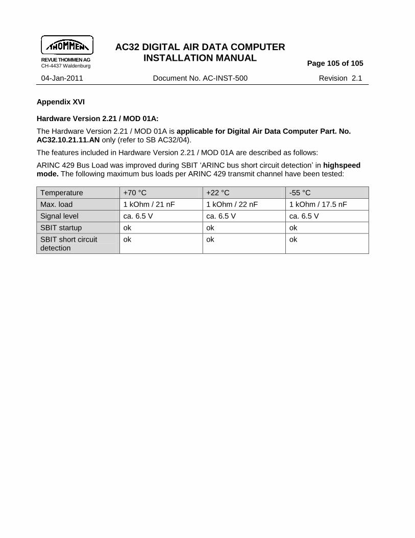
REVUE THOMMEN AG CH-4437 Waldenburg
AC32 DIGITAL AIR DATA COMPUTER INSTALLATION MANUAL
Page 105 of 105
04-Jan-2011 Document No. AC-INST-500 Revision 2.1
Appendix XVI
Hardware Version 2.21 / MOD 01A:
The Hardware Version 2.21 / MOD 01A is applicable for Digital Air Data Computer Part. No. AC32.10.21.11.AN only (refer to SB AC32/04).
The features included in Hardware Version 2.21 / MOD 01A are described as follows:
ARINC 429 Bus Load was improved during SBIT „ARINC bus short circuit detection‟ in highspeed mode. The following maximum bus loads per ARINC 429 transmit channel have been tested:
Temperature +70 °C +22 °C -55 °C
Max. load 1 kOhm / 21 nF 1 kOhm / 22 nF 1 kOhm / 17.5 nF
Signal level ca. 6.5 V ca. 6.5 V ca. 6.5 V
SBIT startup ok ok ok
SBIT short circuit detection
ok ok ok