Rev. 10/31/2017 P-JIB, MANUAL Vestil Manufacturing … MANUAL.pdf · Rev. 10/31/2017 P-JIB, MANUAL...
11
Rev. 10/31/2017 P-JIB, MANUAL Copyright 2017 Vestil Manufacturing Co. Page 1 of 11 P-JIB Portable Jib Crane Instruction Manual Receiving instructions: After delivery, remove the packaging from the product. Inspect the product closely to determine whether it sustained damage during transport. If damage is discovered, immediately record a complete description of the damage on the bill of lading. If the product is undamaged, discard the packaging. Note: The end-user is solely responsible for confirming that product design, installation, use, and maintenance comply with laws, regulations, codes, and mandatory standards applied where the product is used. Vestil Manufacturing Corp. 2999 North Wayne Street, P.O. Box 507, Angola, IN 46703 Telephone: (260) 665-7586 -or- Toll Free (800) 348-0868 Fax: (260) 665-1339 Web: www.vestilmfg.com e-mail: [email protected] Table of Contents Signal words….…………………………………………………………………………………………………………….…………….. 2 Safe use recommendations………………………………………………………………..…………………………………………… 2 FIG. 1A: P-JIB-2 exploded parts diagram & bill of materials……………….……………………………………………………….. 3 FIG. 1B: P-JIB-2 specifications……………………………….…….………………………………………………………………….. 4 FIG. 2A: P-JIB-4 exploded parts diagram & bill of materials…….………………………………………………………………….. 5 FIG. 2B: P-JIB-4 specifications………………………………..…..……………………………………………................................ 6 FIG. 3: Manual hydraulic pump exploded parts diagram & bill of materials……………………………………………………….. 7 Operating the crane…………………………………..…………………………………………………………………… ……………. 8 Operating the hand pump………………..…………………………………………………………………….……………………….. 8 Air bleeding procedure……………………………………………………………………………. …………………………………… 9 Boom length adjustment………………………………………………………………………………………………………………… 9 Inspections & Maintenance……………………………..…………………………………………........................................... 9 - 10 Labeling diagram……...……………………………….………………………………………………………………………………. 10 Limited Warranty…...…………………………………………………………………………………………………………………… 11
Transcript of Rev. 10/31/2017 P-JIB, MANUAL Vestil Manufacturing … MANUAL.pdf · Rev. 10/31/2017 P-JIB, MANUAL...
Rev. 10/31/2017 P-JIB, MANUAL
Copyright 2017 Vestil Manufacturing Co. Page 1 of 11
P-JIB Portable Jib Crane Instruction Manual
Receiving instructions:
After delivery, remove the packaging from the product. Inspect the product closely to determine whether it sustained damage during transport. If damage is discovered, immediately record a complete description of the damage on the bill of lading. If the product is undamaged, discard the packaging. Note:
The end-user is solely responsible for confirming that product design, installation, use, and maintenance comply with laws, regulations, codes, and mandatory standards applied where the product is used.
Vestil Manufacturing Corp. 2999 North Wayne Street, P.O. Box 507, Angola, IN 46703 Telephone: (260) 665-7586 -or- Toll Free (800) 348-0868
Fax: (260) 665-1339 Web: www.vestilmfg.com e-mail: [email protected]
Table of Contents Signal words….…………………………………………………………………………………………………………….…………….. 2 Safe use recommendations………………………………………………………………..…………………………………………… 2 FIG. 1A: P-JIB-2 exploded parts diagram & bill of materials……………….……………………………………………………….. 3 FIG. 1B: P-JIB-2 specifications……………………………….…….………………………………………………………………….. 4 FIG. 2A: P-JIB-4 exploded parts diagram & bill of materials…….………………………………………………………………….. 5 FIG. 2B: P-JIB-4 specifications………………………………..…..……………………………………………................................ 6 FIG. 3: Manual hydraulic pump exploded parts diagram & bill of materials……………………………………………………….. 7 Operating the crane…………………………………..…………………………………………………………………… ……………. 8 Operating the hand pump………………..…………………………………………………………………….……………………….. 8 Air bleeding procedure……………………………………………………………………………. …………………………………… 9 Boom length adjustment………………………………………………………………………………………………………………… 9 Inspections & Maintenance……………………………..…………………………………………........................................... 9 - 10 Labeling diagram……...……………………………….………………………………………………………………………………. 10 Limited Warranty…...…………………………………………………………………………………………………………………… 11

Rev. 10/31/2017 P-JIB, MANUAL
Copyright 2017 Vestil Manufacturing Co. Page 2 of 11
Signal Words: This manual uses SIGNAL WORDS to indicate the likelihood of personal injuries, as well as the probable
seriousness of those injuries, if the product is misused in the ways described. Other signal words call attention to uses of the product likely cause property damage. The signal words used in this manual appear below along with their definitions.
Identifies a hazardous situation which, if not avoided, WILL result in DEATH or SERIOUS INJURY. Use of this signal word is limited to the most extreme situations.
Identifies a hazardous situation which, if not avoided, COULD result in DEATH or SERIOUS INJURY.
Indicates a hazardous situation which, if not avoided, COULD result in MINOR or MODERATE injury.
Identifies practices likely to result in product/property damage, such as operation that might damage the product.
Safe use recommendations: We strive to identify hazards associated with the use of our products. However, material handling is inherently
dangerous and no manual can address every risk. The end-user ultimately is responsible for exercising sound judgment at all times during use of this product.
Material handling is dangerous. Improper or careless operation might result in serious personal injuries sustained by the operator and bystanders. Always apply material handling techniques, including rigging methods, learned during training and use the product properly: Failure to read and understand the entire manual before assembling, using, or servicing the product constitutes misuse. Read the manual to refresh your understanding of proper use and maintenance procedures as necessary. DO NOT attempt to lift items that weigh more than the capacity of your crane. Capacity decreases as boom length increases. Capacities of both models appear in FIGS. 1B & 2B on pp. 4 and 6. DO NOT stand or sit on either the crane or the load. Avoid contact with the casters. Stand clear of the load while raising and lowering it. ONLY use the crane on even, level, improved surfaces (concrete or asphalt) capable of supporting the combined weight of the crane and a full capacity load. DO NOT attempt to move the crane up or down sloped surfaces. DO NOT perform maintenance on this crane UNLESS it is unloaded and the casters are chocked to prevent movement. If the crane requires repair, ONLY install manufacturer-approved replacement parts. DO NOT begin to raise a load until the load hook is centered above it. ALWAYS observe the boom while raising and lowering a load. It should rise smoothly. Watch for binding or jerky movement and listen for unusual noises. DO NOT use the crane unless it is in normal operating condition. Inspect the unit before each use following the inspection instructions on p. 9-10 to determine whether it is functioning normally. Always watch the load carefully while raising and lowering the boom. DO NOT continue to move the pump handle back-and-forth if the boom is fully elevated (does not continue to rise). Always lower and disconnect the load before leaving the crane unattended. Relieve hydraulic pressure by turning the release lever counterclockwise until the boom begins to descend. Lower the boom completely; then close the release valve. DO NOT alter the pressure relief valve setting! DO NOT use the crane UNLESS it is labeled as shown in “Labeling diagram” on p. 10. DO NOT modify this crane in any way. Modifications automatically void the limited warranty and might make the crane unsafe to use. Always make sure that the shackle pin (see item 35 on p. 3; item 34 on p. 5) is secure before applying a load to the
stationary hook. Tighten the screw pin before each use.
Proper maintenance is essential for this product to function properly. Follow the inspection and maintenance procedures provided on pp. 9-10. If repairs are necessary, only install manufacturer-approved replacement parts. Periodically lubricate pivot points. Keep the crane clean & dry.
Rev. 10/31/2017 P-JIB, MANUAL
Copyright 2017 Vestil Manufacturing Co. Page 3 of 11
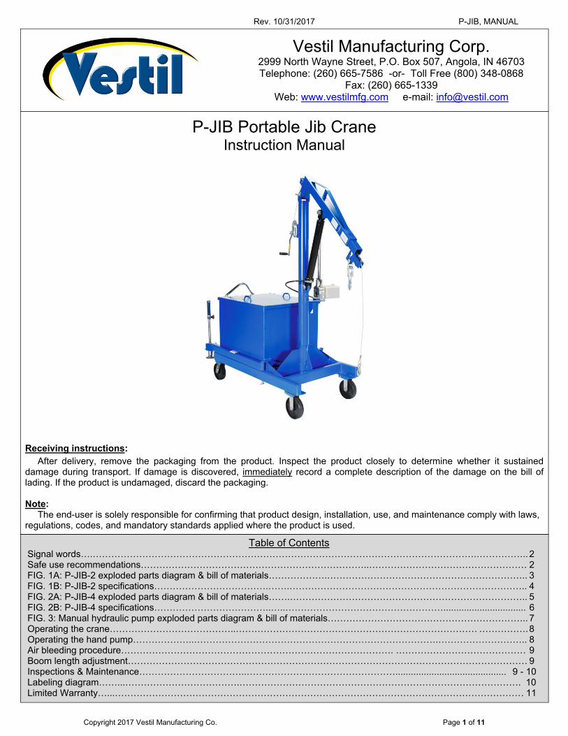
FIG. 1A: P-JIB-2 Exploded Parts Diagram & Bill of Materials
Item Part no. Description Qty. Item Part no. Description Qty.
1 28-514-208 Weldment, base 1 20 11324 Hex bolt, 5/8”-11x51/2” 1
2 28-514-202 Weldment, boom, inner 1 21 33016 Flat washer, low carbon, USS, zinc-plated, 5/8”
1
3 28-514-203 Weldment, boom, outer 1 22 37036 Nylock nut, zinc-plated, 5/8”-11 1
4 28-514-205 Weldment, mast 1 23 66122 1/2”x4” clevis pin 1
5 28/-514-206 Weldment, outrigger 2 24 28-110-001-001 Inner bearing 1
6 28-514-207 Weldment, lid 1 25 11101 Hex bolt, 3/8”-16x1/2” 3
7 16-025-025 Handle, formed, HT/ergo handle 1 26 33622 Split lock washer, carbon steel, medium zinc-finish, 3/8”
3
8 11105 Hex bolt, grade A, zinc-plated, 3/8”-16x1” 2 27 33004 Flat washer, USS, zinc-plated, 1/4” 4
9 33008 Flat washer, low carbon, USS, zinc-plated, 3/8”
2 28 36102 Hex nut, grade A, zinc plated, 1/4”-20 4
10 37024 Nylon insert lock nut, grade 2, zinc finish, 3/8”-16
2 29 16-132-208 Caster, 8”x2”, swivel 2
11 65076 1/8”x1” cotter pin, zinc-plated 4 30 16-132-233 Caster, rigid, GFN-8/2-R 2
12 99-112-006 Pin, clevis 4 31 21-042-002-001 Hand winch, foldable handle grip 1
13 08-145-001 Swivel hook, 2-ton capacity 2 32 08-145-010 Shackle, 1/2”, 2-ton capacity 1
14 45286 #11 hitch pin clip, 1/8”x25/8” 3 33 47-112-001 Clevis pin, 1” x 31/4” 2
15 65127 Cotter pin, zinc-plated, 3/16”-2 4 34 99-027-003 1/4” cable pulley, 3” OD, 1/2” ID 2
16 30-001-011 Leveling jack 2 35 99-021-948 Cylinder, hydraulic, 2”x18” stroke 1
17 11007 Hex bolt, 1/4”- 20UNC x11/4” 16 36 99-140-003-001 Pump, manual, hand pump 1
18 37018 Nylock nut, grade 2, zinc-finish, 1/4”-20 12 37 01-023-008 Reservoir, oil 1
19 28-612-005 Weldment, outrigger pin 2 38 21-112-003 Pin, 1/2” x 115/16” retaining clevis 2
Rev. 10/31/2017 P-JIB, MANUAL
Copyright 2017 Vestil Manufacturing Co. Page 4 of 11
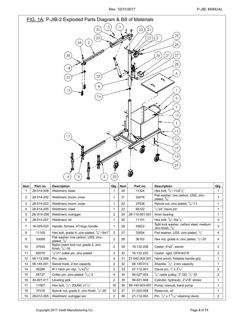
FIG 1B: P-JIB-2 specifications
The inner boom has 4 pin holes spaced 7 inches apart to allow boom length to be adjusted. Boom length determines the maximum rated load of the crane, which decreases as boom length increases as indicated in the table below.
Rev. 10/31/2017 P-JIB, MANUAL
Copyright 2017 Vestil Manufacturing Co. Page 5 of 11
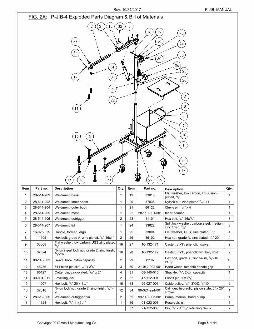
FIG. 2A: P-JIB-4 Exploded Parts Diagram & Bill of Materials
Item Part no. Description Qty. Item Part no. Description Qty.
1 28-514-209 Weldment, base 1 19 33016 Flat washer, low carbon, USS, zinc-plated, 5/8”
1
2 28-514-202 Weldment, inner boom 1 20 37036 Nylock nut, zinc-plated, 5/8”-11 1
3 28-514-204 Weldment, outer boom 1 21 66122 Clevis pin, 1/2” x 4 1
4 28-514-205 Weldment, mast 1 22 28-110-001-001 Inner bearing 1
5 28-514-206 Weldment, outrigger 2 23 11101 Hex bolt, 3/8”-16x1/2” 3
6 28-514-207 Weldment, lid 1 24 33622 Split lock washer, carbon steel, medium zinc finish, 3/8”
3
7 16-025-025 Handle, formed, ergo 1 25 33004 Flat washer, USS, zinc plated, 1/4” 4
8 11105 Hex bolt, grade A, zinc plated, 3/8”-16x1” 2 26 36102 Hex nut, grade A, zinc plated, 1/4”-20 4
9 33008 Flat washer, low carbon, USS zinc plated, 3/8”
18 27 16-132-171 Caster, 8”x3”, phenolic, swivel 2
10 37024 Nylon insert lock nut, grade 2, zinc finish, 3/8”-16
18 28 16-132-172 Caster, 8”x3”, phenolic w/ fiber, rigid 2
11 08-145-001 Swivel hook, 2-ton capacity 2 29 11107 Hex bolt, grade A, zinc finish, 3/8”-16 x11/4”
16
12 45286 #11 hitch pin clip, 1/8” x 25/8” 3 30 21-042-002-001 Hand winch, foldable handle grip 1
13 65127 Cotter pin, zinc-plated, 3/16” x 2” 4 31 08-145-010 Shackle, 1/2”, 2-ton capacity 1
14 30-001-011 Levelling jack 2 32 47-112-001 Clevis pin, 1”x31/4” 2
15 11007 Hex bolt, 1/4”-20 x 11/4” 16 33 99-027-003 Cable pulley, 1/4”, 3”OD, 1/2”ID 2
16 37018 Nylon lock nut, grade 2, zinc-finish, 1/4” -20
12 34 99-021-924-001 Cylinder, hydraulic, piston style, 3” x 20” stroke
1
17 28-612-005 Weldment, outrigger pin 2 35 99-140-003-001 Pump, manual, hand pump 1
18 11324 Hex bolt, 5/8”-11x51/2” 1 36 01-023-008 Reservoir, oil 1
37 21-112-003 Pin, 1/2” x 115/16” retaining clevis 2
Rev. 10/31/2017 P-JIB, MANUAL
Copyright 2017 Vestil Manufacturing Co. Page 6 of 11
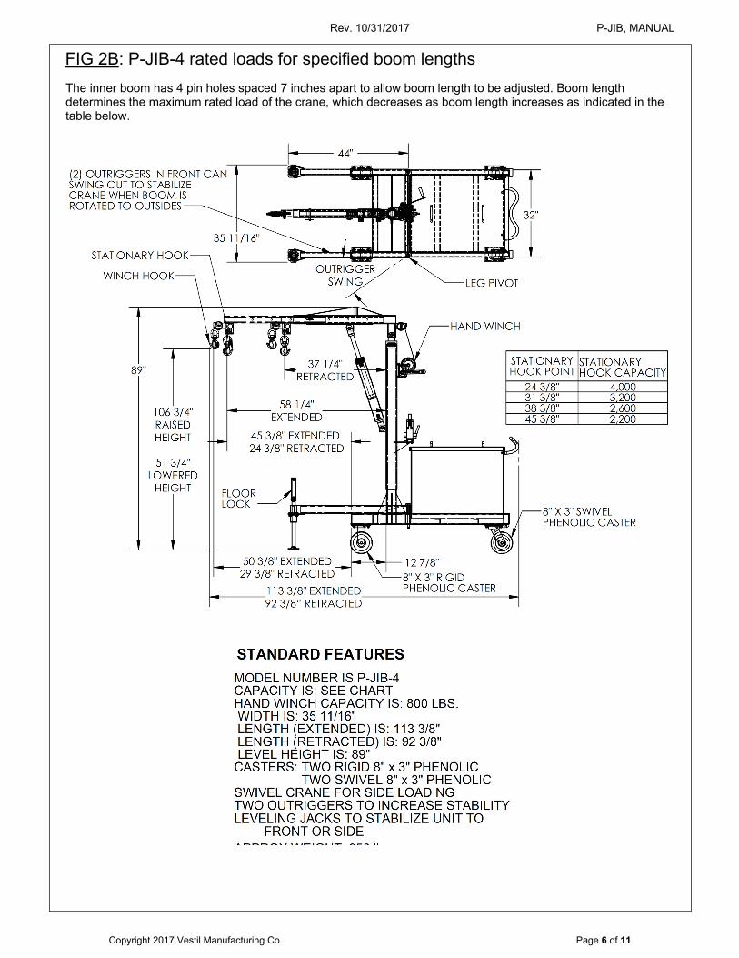
FIG 2B: P-JIB-4 rated loads for specified boom lengths The inner boom has 4 pin holes spaced 7 inches apart to allow boom length to be adjusted. Boom length determines the maximum rated load of the crane, which decreases as boom length increases as indicated in the table below.
Rev. 10/31/2017 P-JIB, MANUAL
Copyright 2017 Vestil Manufacturing Co. Page 7 of 11
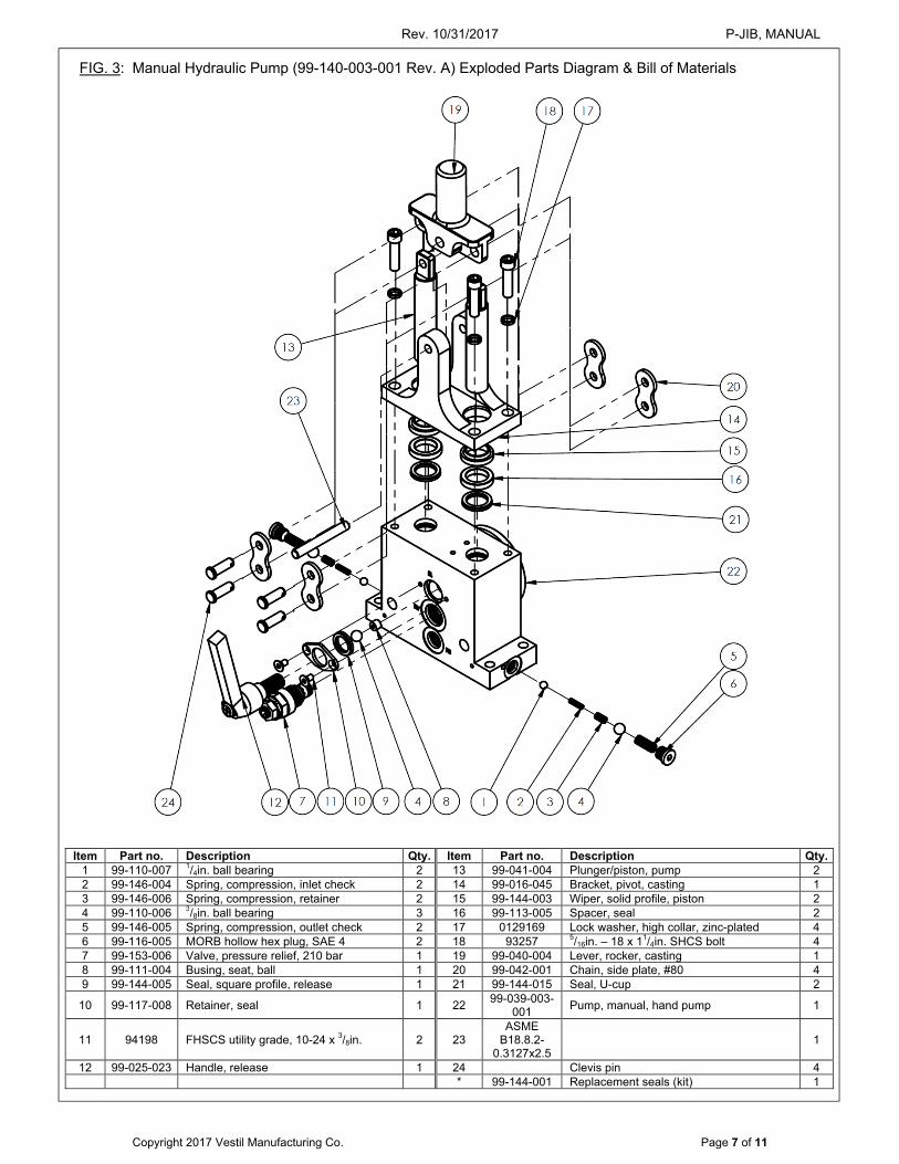
FIG. 3: Manual Hydraulic Pump (99-140-003-001 Rev. A) Exploded Parts Diagram & Bill of Materials
Item Part no. Description Qty. Item Part no. Description Qty. 1 99-110-007 1/4in. ball bearing 2 13 99-041-004 Plunger/piston, pump 2 2 99-146-004 Spring, compression, inlet check 2 14 99-016-045 Bracket, pivot, casting 1 3 99-146-006 Spring, compression, retainer 2 15 99-144-003 Wiper, solid profile, piston 2 4 99-110-006 3/8in. ball bearing 3 16 99-113-005 Spacer, seal 2 5 99-146-005 Spring, compression, outlet check 2 17 0129169 Lock washer, high collar, zinc-plated 4 6 99-116-005 MORB hollow hex plug, SAE 4 2 18 93257 5/16in. – 18 x 11/4in. SHCS bolt 4 7 99-153-006 Valve, pressure relief, 210 bar 1 19 99-040-004 Lever, rocker, casting 1 8 99-111-004 Busing, seat, ball 1 20 99-042-001 Chain, side plate, #80 4 9 99-144-005 Seal, square profile, release 1 21 99-144-015 Seal, U-cup 2
10 99-117-008 Retainer, seal 1 22 99-039-003-
001 Pump, manual, hand pump 1
11 94198 FHSCS utility grade, 10-24 x 3/8in. 2 23 ASME
B18.8.2-0.3127x2.5
1
12 99-025-023 Handle, release 1 24 Clevis pin 4 * 99-144-001 Replacement seals (kit) 1
Rev. 10/31/2017 P-JIB, MANUAL
Copyright 2017 Vestil Manufacturing Co. Page 8 of 11
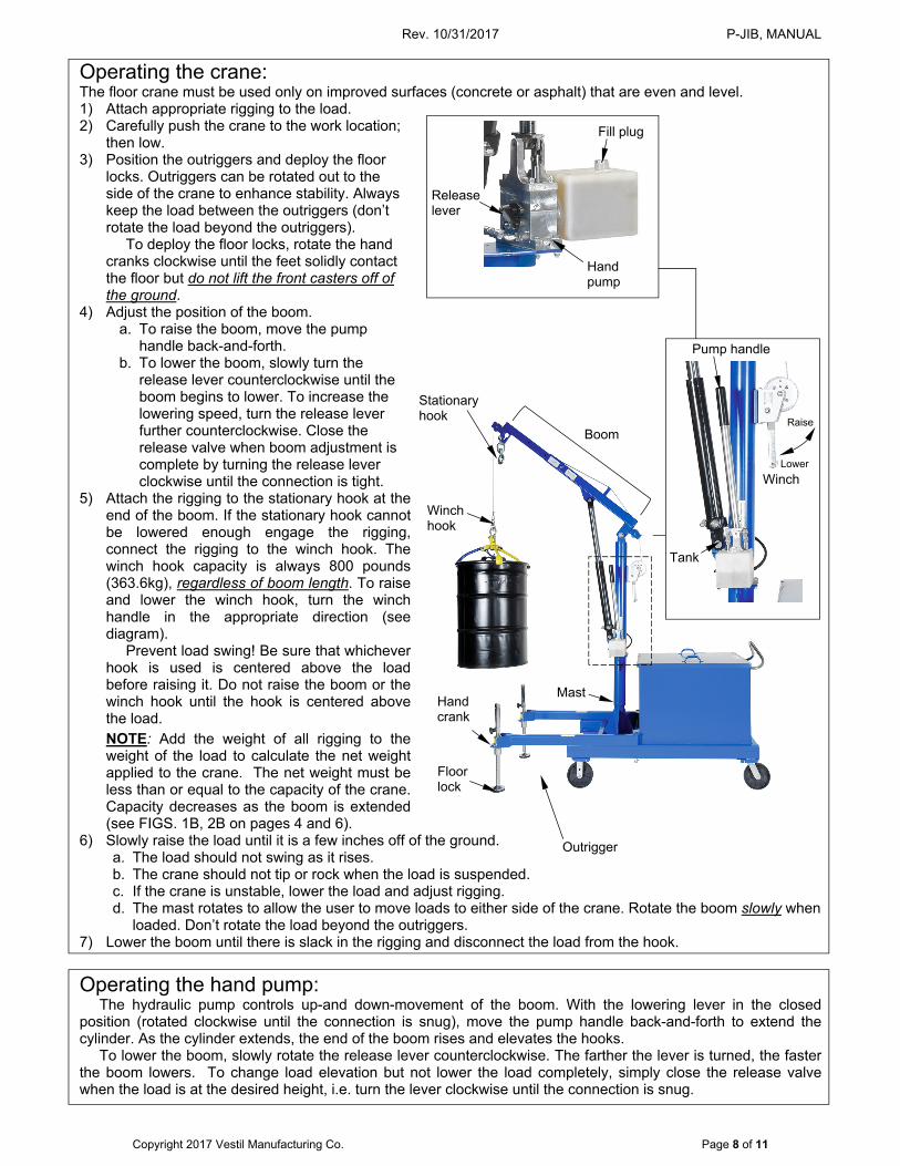
Operating the crane: The floor crane must be used only on improved surfaces (concrete or asphalt) that are even and level. 1) Attach appropriate rigging to the load. 2) Carefully push the crane to the work location;
then low. 3) Position the outriggers and deploy the floor
locks. Outriggers can be rotated out to the side of the crane to enhance stability. Always keep the load between the outriggers (don’t rotate the load beyond the outriggers).
To deploy the floor locks, rotate the hand cranks clockwise until the feet solidly contact the floor but do not lift the front casters off of the ground.
4) Adjust the position of the boom. a. To raise the boom, move the pump
handle back-and-forth. b. To lower the boom, slowly turn the
release lever counterclockwise until the boom begins to lower. To increase the lowering speed, turn the release lever further counterclockwise. Close the release valve when boom adjustment is complete by turning the release lever clockwise until the connection is tight.
5) Attach the rigging to the stationary hook at the end of the boom. If the stationary hook cannot be lowered enough engage the rigging, connect the rigging to the winch hook. The winch hook capacity is always 800 pounds (363.6kg), regardless of boom length. To raise and lower the winch hook, turn the winch handle in the appropriate direction (see diagram).
Prevent load swing! Be sure that whichever hook is used is centered above the load before raising it. Do not raise the boom or the winch hook until the hook is centered above the load.
NOTE: Add the weight of all rigging to the weight of the load to calculate the net weight applied to the crane. The net weight must be less than or equal to the capacity of the crane. Capacity decreases as the boom is extended (see FIGS. 1B, 2B on pages 4 and 6).
6) Slowly raise the load until it is a few inches off of the ground. a. The load should not swing as it rises. b. The crane should not tip or rock when the load is suspended. c. If the crane is unstable, lower the load and adjust rigging. d. The mast rotates to allow the user to move loads to either side of the crane. Rotate the boom slowly when
loaded. Don’t rotate the load beyond the outriggers. 7) Lower the boom until there is slack in the rigging and disconnect the load from the hook.
Operating the hand pump: The hydraulic pump controls up-and down-movement of the boom. With the lowering lever in the closed
position (rotated clockwise until the connection is snug), move the pump handle back-and-forth to extend the cylinder. As the cylinder extends, the end of the boom rises and elevates the hooks.
To lower the boom, slowly rotate the release lever counterclockwise. The farther the lever is turned, the faster the boom lowers. To change load elevation but not lower the load completely, simply close the release valve when the load is at the desired height, i.e. turn the lever clockwise until the connection is snug.
Stationary hook
Winch hook
Floor lock
Boom
Winch
Raise
Lower
Tank
Pump handle
Fill plug
Release lever
Hand pump
Hand crank
Mast
Outrigger
Rev. 10/31/2017 P-JIB, MANUAL
Copyright 2017 Vestil Manufacturing Co. Page 9 of 11
Inspections & Maintenance: Before using the crane for the first time, make a written record of its appearance. Include observations about
each part of the crane, such as pivot points and pins, the hydraulic system (cylinder, pump, hoses, and oil tank), hooks, shackles and shackle pins, floor locks, casters, mast, boom, and supporting frame. Raise and lower the boom. Include notes about how easily the handle moves back-and-forth, as well as sounds heard during operation.
This record establishes “normal condition”. During future inspections, compare current observations to the written record to determine if the unit is in normal condition. DO NOT use the crane unless it is in normal condition. If repairs are necessary, only install manufacturer-approved replacement parts. (A) Before each use, inspect the following items:
1.) Frame, mast, cylinder brackets (where cylinder attaches to mast and boom), & booms (inner and outer) ─ examine each item for damage and severe wear.
2.) Cylinder and pump ─ check for oil leaks. Raise and lower the boom. Listen for unusual noises; watch the cylinder. Confirm that it extends and retracts smoothly.
3.) Load hook and shackle ─ closely examine the load hook and shackle. Make sure that neither is severely worn, warped, bending or cracking. Confirm that the safety latch (of the hook) operates correctly. Also inspect the shackle bracket. The bracket should be square and rigid and lack cracks and significant bends. The pin hole (for the shackle pin) should not be elongated.
4.) Shackle and shackle pin: make sure that the shackle and pin are not bent, cracked, stretched, or severely worn. The opening in the lifting arm for the shackle should not be stretched, bent or cracked.
5.) Inner and outer booms: confirm that both parts are rigid and square. 6.) Make a dated record of the repairs, adjustments and replacements made.
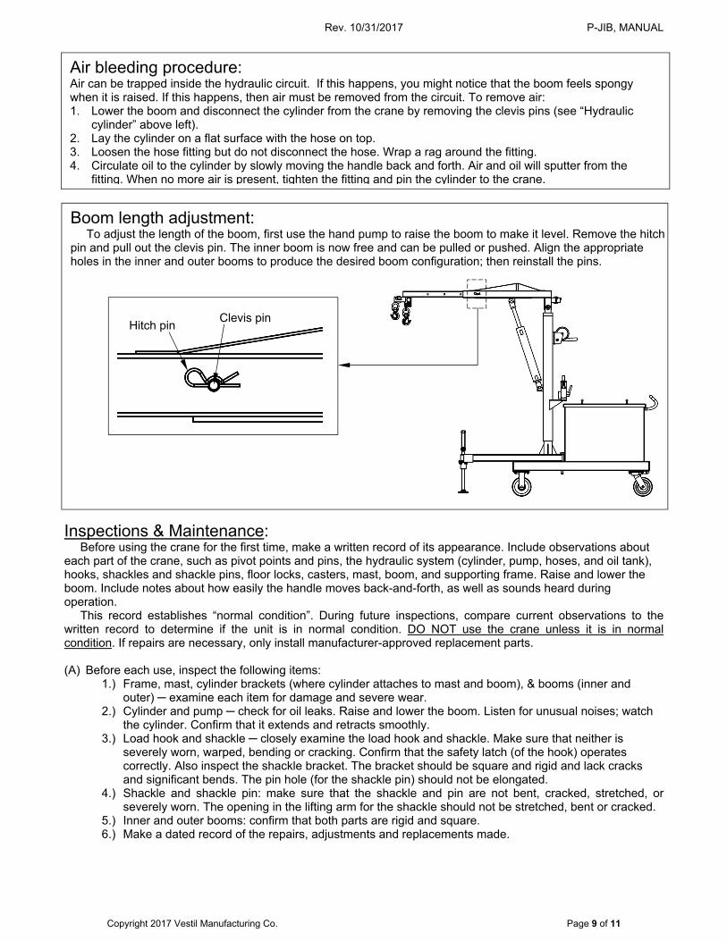
Air bleeding procedure: Air can be trapped inside the hydraulic circuit. If this happens, you might notice that the boom feels spongy when it is raised. If this happens, then air must be removed from the circuit. To remove air: 1. Lower the boom and disconnect the cylinder from the crane by removing the clevis pins (see “Hydraulic
cylinder” above left). 2. Lay the cylinder on a flat surface with the hose on top. 3. Loosen the hose fitting but do not disconnect the hose. Wrap a rag around the fitting. 4. Circulate oil to the cylinder by slowly moving the handle back and forth. Air and oil will sputter from the
fitting. When no more air is present, tighten the fitting and pin the cylinder to the crane.
Boom length adjustment: To adjust the length of the boom, first use the hand pump to raise the boom to make it level. Remove the hitch
pin and pull out the clevis pin. The inner boom is now free and can be pulled or pushed. Align the appropriate holes in the inner and outer booms to produce the desired boom configuration; then reinstall the pins.
Hitch pin
Clevis pin
Rev. 10/31/2017 P-JIB, MANUAL
Copyright 2017 Vestil Manufacturing Co. Page 10 of 11
(B) Inspect the following at least once per month: 1.) Oil level ─ lower the boom completely. Oil should be within ¾in. of the top of the tank with the boom in
the fully lowered position. [See “Yearly inspection”, p. 10 for hydraulic fluid specifications.] 2.) Hoses ─ check for cuts, kinks, and other damage. Confirm that the ends of the hose are firmly
fastened to the pump and the cylinder. 3.) Hardware ─ check the integrity of all nuts, bolts, and pins. Replace any item that is damaged. 4.) Casters ─ move the crane and determine whether any caster is loose, severely worn, or damaged.
Remove material from the surface of the casters. Replace casters that do not roll smoothly or are bent or cracked.
5.) Winch, cable, and pulleys – examine the cable for frays, broken strands, kinks, etc. Make sure that the cable clamp (connects the hook to the cable) is secure. Make sure that all pulleys and retaining hardware are in normal condition.
6.) Labels ─ check all information/safety labels. The crane should be labeled at all times as shown in the labeling diagram on p. 10.
(C) Yearly inspection: In addition to the inspections described above in parts A and B, check the hydraulic fluid at least once per
year. Change the oil if it darkens, becomes gritty, or turns a milky color (indicating the presence of water). Replace the hydraulic fluid with anti-wear hydraulic oil of viscosity grade 150 SUS at 100°F, (ISO 32 at 40°C). Examples of proper hydraulic fluid are AW 32 and HO 150 hydraulic oil, and non-synthetic transmission fluid. You may use a synthetic transmission fluid if you flush the system with the synthetic fluid before filling the reservoir.
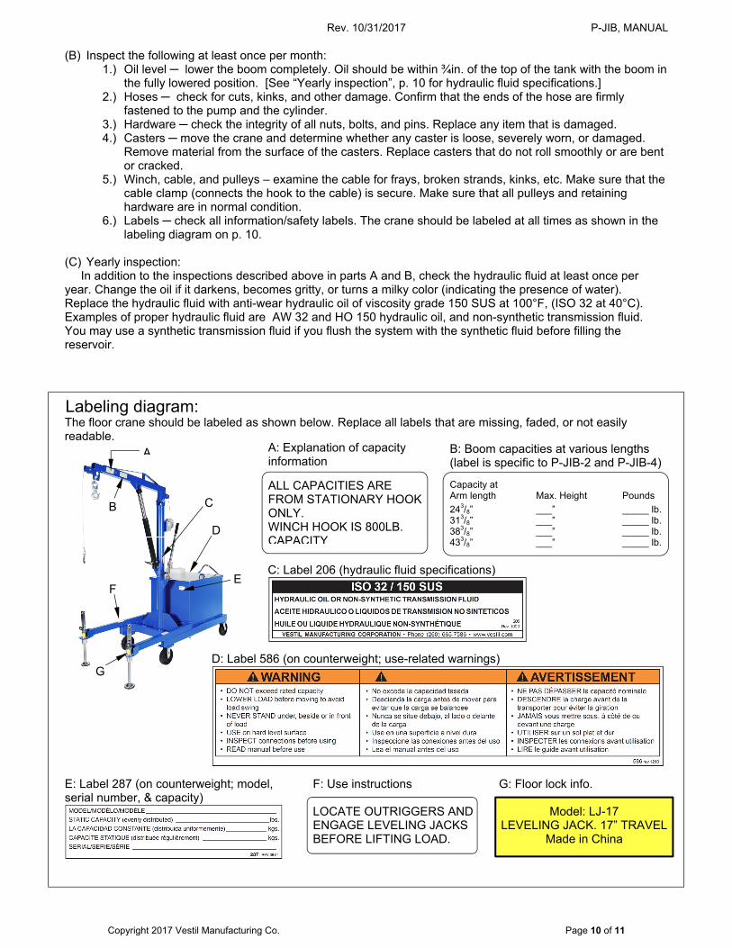
The floor crane should be labeled as shown below. Replace all labels that are missing, faded, or not easily readable.
Labeling diagram:
E: Label 287 (on counterweight; model, serial number, & capacity)
D: Label 586 (on counterweight; use-related warnings)
C: Label 206 (hydraulic fluid specifications)
A
B C
D
A: Explanation of capacity information
B: Boom capacities at various lengths (label is specific to P-JIB-2 and P-JIB-4) Capacity at Arm length Max. Height Pounds
243/8” ___” _____ lb. 313/8” ___” _____ lb. 383/8” ___” _____ lb. 433/8” ___” _____ lb.
ALL CAPACITIES ARE FROM STATIONARY HOOK ONLY. WINCH HOOK IS 800LB. CAPACITY
E F
G
F: Use instructions LOCATE OUTRIGGERS AND ENGAGE LEVELING JACKS BEFORE LIFTING LOAD.
G: Floor lock info.
Model: LJ-17 LEVELING JACK. 17” TRAVEL
Made in China

Rev. 10/31/2017 P-JIB, MANUAL
Copyright 2017 Vestil Manufacturing Co. Page 11 of 11
LIMITED WARRANTY
Vestil Manufacturing Corporation (“Vestil”) warrants this product to be free of defects in material and workmanship during the warranty period. Our warranty obligation is to provide a replacement for a defective original part if the part is covered by the warranty, after we receive a proper request from the warrantee (you) for warranty service.
Who may request service? Only a warrantee may request service. You are a warrantee if you purchased the product from Vestil or from an authorized distributor AND Vestil has been fully paid.
What is an “original part”? An original part is a part used to make the product as shipped to the warrantee.
What is a “proper request”? A request for warranty service is proper if Vestil receives: 1) a photocopy of the Customer Invoice that displays the shipping date; AND 2) a written request for warranty service including your name and phone number. Send requests by any of the following methods:
Mail Fax Email Vestil Manufacturing Corporation (260) 665-1339 [email protected] 2999 North Wayne Street, PO Box 507 Phone Angola, IN 46703 (260) 665-7586
In the written request, list the parts believed to be defective and include the address where replacements should be delivered.
What is covered under the warranty? After Vestil receives your request for warranty service, an authorized representative will contact you to determine whether your claim is covered by the warranty. Before providing warranty service, Vestil may require you to send the entire product, or just the defective part or parts, to its facility in Angola, IN. The warranty covers defects in the following original dynamic components: motors, hydraulic pumps, electronic controllers, switches and cylinders. It also covers defects in original parts that wear under normal usage conditions (“wearing parts”), such as bearings, hoses, wheels, seals, brushes, and batteries.
How long is the warranty period? The warranty period for original dynamic components is 90 days. For wearing parts, the warranty period is 90 days. The warranty periods begin on the date when Vestil ships the product to the warrantee. If the product was purchased from an authorized distributor, the periods begin when the distributor ships the product. Vestil may, at its sole discretion, extend the warranty periods for products shipped from authorized distributors by up to 30 days to account for shipping time.
If a defective part is covered by the warranty, what will Vestil do to correct the problem? Vestil will provide an appropriate replacement for any covered part. An authorized representative of Vestil will contact you to discuss your claim.
What is not covered by the warranty? 1. Labor; 2. Freight; 3. Occurrence of any of the following, which automatically voids the warranty:
Product misuse; Negligent operation or repair; Corrosion or use in corrosive environments; Inadequate or improper maintenance; Damage sustained during shipping; Collisions or other incidental contacts causing damage to the product; Unauthorized modifications: DO NOT modify the product IN ANY WAY without first receiving written
authorization from Vestil. Modification(s) might make the product unsafe to use or might cause excessive and/or abnormal wear.
Do any other warranties apply to the product? Vestil Manufacturing Corp. makes no other express warranties. All implied warranties are disclaimed to the extent allowed by law. Any implied warranty not disclaimed is limited in scope to the terms of this Limited Warranty.