RESEARCH Open Access New indoor navigation system … · RESEARCH Open Access New indoor navigation...
10
RESEARCH Open Access New indoor navigation system for visually impaired people using visible light communication Madoka Nakajima * and Shinichiro Haruyama Abstract In this study, we propose an indoor navigation system that utilizes visible light communication technology, which employs LED lights and a geomagnetic correction method, aimed at supporting visually impaired people who travel indoors. To verify the effectiveness of this system, we conducted an experiment targeting visually impaired people. Although acquiring accurate positional information and detecting directions indoors is difficult, we confirmed that using this system, accurate positional information and travel direction can be obtained utilizing visible light communication technology, which employs LED lights, and correcting the values of the geomagnetic sensor integrated in a smartphone. Keywords: Indoor navigation, Visible light communication, Visually impaired people, Location-based services 1. Introduction Pedestrian support for visually impaired people involves the use of textured paving blocks, guide dogs, GPS- based voice navigation systems, among others. On the other hand, studies aimed at visually impaired people report that there is a need for voice information inside buildings [1], and that, in the future, we will need adequate indoor pedestrian support systems in large commercial facilities, such as shopping centers and underground shopping malls. However, compared to public spaces and transport facilities, no progress is being made in providing commercial facilities with textured paving blocks [2], and although guide dogs are effective on obstacle-free safe walkways, they cannot lo- cate a person’ s destination. Moreover, the GPS’ inability to give an accurate position indoors is equally a prob- lem. Therefore, positioning methods using radio waves emitted from a wireless LAN access point are increas- ingly employed. However, this method has encountered issues with fluctuating positional accuracy due to re- flected signals from the wireless LAN, obstacles, or the surrounding environment [3]. Studies into guidance systems using tactile maps, which are effective in creat- ing mental maps, are also underway. However, it takes time to understand a tactile map by touch, and there- fore, they are difficult to use while on the move. To ad- dress these kinds of issues, our study aims to create a usable system that enables visually impaired people, es- pecially the blind, to travel indoors unaided. A variety of data is required to travel indoors, such as the accurate current position, travel direction, distance to the destin- ation, and information about the barriers and sur- roundings. This study concentrates on solving problems relating to the current position, the travel direction, and the distance. As an indoor positioning method, we fo- cussed on visible light communication technology using the ubiquitous LED lighting. As LED lighting is often in- stalled in pathway ceilings, accurate positional informa- tion can be sent naturally from above the user’ s head. Further, we used the geomagnetic sensor in the already widespread smartphone for a method to survey the travel direction. However, because of situations where geomagnetic sensors cannot detect the accurate direc- tion due to the effect of, for example [4], rebars, and be- cause it has been reported that they are not adequate to maintain the correct direction when walking long distances [5-7], we worked on simply improving the dir- ectional accuracy by obtaining and correcting the * Correspondence: [email protected] Graduate school of System design and management, Keio University, Collaboration Complex, 4-1-1 Hiyoshi, Kohoku-ku, Yokohama, Kanagawa 223-8526, Japan © 2013 Nakajima and Haruyama; licensee Springer. This is an Open Access article distributed under the terms of the Creative Commons Attribution License (http://creativecommons.org/licenses/by/2.0), which permits unrestricted use, distribution, and reproduction in any medium, provided the original work is properly cited. Nakajima and Haruyama EURASIP Journal on Wireless Communications and Networking 2013, 2013:37 http://jwcn.eurasipjournals.com/content/2013/1/37
Transcript of RESEARCH Open Access New indoor navigation system … · RESEARCH Open Access New indoor navigation...

Nakajima and Haruyama EURASIP Journal on Wireless Communications and Networking 2013, 2013:37http://jwcn.eurasipjournals.com/content/2013/1/37
RESEARCH Open Access
New indoor navigation system for visuallyimpaired people using visible lightcommunicationMadoka Nakajima* and Shinichiro Haruyama
Abstract
In this study, we propose an indoor navigation system that utilizes visible light communication technology, whichemploys LED lights and a geomagnetic correction method, aimed at supporting visually impaired people whotravel indoors. To verify the effectiveness of this system, we conducted an experiment targeting visually impairedpeople. Although acquiring accurate positional information and detecting directions indoors is difficult, weconfirmed that using this system, accurate positional information and travel direction can be obtained utilizingvisible light communication technology, which employs LED lights, and correcting the values of the geomagneticsensor integrated in a smartphone.
Keywords: Indoor navigation, Visible light communication, Visually impaired people, Location-based services
1. IntroductionPedestrian support for visually impaired people involvesthe use of textured paving blocks, guide dogs, GPS-based voice navigation systems, among others. On theother hand, studies aimed at visually impaired peoplereport that there is a need for voice information insidebuildings [1], and that, in the future, we will needadequate indoor pedestrian support systems in largecommercial facilities, such as shopping centers andunderground shopping malls. However, compared topublic spaces and transport facilities, no progress isbeing made in providing commercial facilities withtextured paving blocks [2], and although guide dogs areeffective on obstacle-free safe walkways, they cannot lo-cate a person’s destination. Moreover, the GPS’ inabilityto give an accurate position indoors is equally a prob-lem. Therefore, positioning methods using radio wavesemitted from a wireless LAN access point are increas-ingly employed. However, this method has encounteredissues with fluctuating positional accuracy due to re-flected signals from the wireless LAN, obstacles, or thesurrounding environment [3]. Studies into guidance
* Correspondence: [email protected] school of System design and management, Keio University,Collaboration Complex, 4-1-1 Hiyoshi, Kohoku-ku, Yokohama, Kanagawa223-8526, Japan
© 2013 Nakajima and Haruyama; licensee SprinCommons Attribution License (http://creativecoreproduction in any medium, provided the orig
systems using tactile maps, which are effective in creat-ing mental maps, are also underway. However, it takestime to understand a tactile map by touch, and there-fore, they are difficult to use while on the move. To ad-dress these kinds of issues, our study aims to create ausable system that enables visually impaired people, es-pecially the blind, to travel indoors unaided. A variety ofdata is required to travel indoors, such as the accuratecurrent position, travel direction, distance to the destin-ation, and information about the barriers and sur-roundings. This study concentrates on solving problemsrelating to the current position, the travel direction, andthe distance. As an indoor positioning method, we fo-cussed on visible light communication technology usingthe ubiquitous LED lighting. As LED lighting is often in-stalled in pathway ceilings, accurate positional informa-tion can be sent naturally from above the user’s head.Further, we used the geomagnetic sensor in the alreadywidespread smartphone for a method to survey thetravel direction. However, because of situations wheregeomagnetic sensors cannot detect the accurate direc-tion due to the effect of, for example [4], rebars, and be-cause it has been reported that they are not adequate tomaintain the correct direction when walking longdistances [5-7], we worked on simply improving the dir-ectional accuracy by obtaining and correcting the
ger. This is an Open Access article distributed under the terms of the Creativemmons.org/licenses/by/2.0), which permits unrestricted use, distribution, andinal work is properly cited.

Nakajima and Haruyama EURASIP Journal on Wireless Communications and Networking 2013, 2013:37 Page 2 of 10http://jwcn.eurasipjournals.com/content/2013/1/37
geomagnetic information beneath the LED lights inadvance.This article is structured as follows. In section 2, we
present the necessary components of an indoor naviga-tion system, namely, visible light communication tech-nology and indoor map data, and then, we will discussin detail the correction method for the pedestrian’s pos-ition and direction detection. In section 3, we presentthe design and implementation method of the indoornavigation system, and in section 4, we present the testresults for this indoor navigation system. Section 5discusses this system, and section 6 presents the con-clusions and future research.
2. Our approachIn this section, we describe the positioning method andthe method for creating indoor map data through visiblelight communication, components of our ‘indoor naviga-tion system’ and the direction detection method throughgeomagnetism.
Figure 1 Using visible light communication.
2.1 Positioning for visible light communicationAs mentioned previously, methods used for indoorpositioning make estimates from the position or radiowave strength of the wireless LAN access point or usewireless active tags. However, these methods have issueswith fluctuating positional accuracy due to environmen-tal factors such as obstacles. This makes them difficultto use as a support for visually impaired people in theirtravels. Therefore, we have focussed on visible lightcommunication technology using LED lights. Whenusing visible light communication, it becomes possibleto identify the user’s position within a range of 1–2m.Moreover, visible light communications technologyenables users to find out which floor they are locatedon. The indoor positioning system by visible light com-munication, Wireless LAN and, RFID which use is
Table 1 Indoor positioning system
Visible lightcommunication
Wireless LAN RFID
Positionaccuracy
several meters several meters toseveral hundredmeters
several meters
Quality stable dependence ofnoise, interference
dependence ofnoise,interference
Measurementtime
less than asecond
several seconds less than asecond
Recognitionof buildingfloors
possible difficult possible
MeasurementDevice
visible lightreceiver
Wi-Fi transceiver RFID reader
being investigated, are shown in Table 1 [8-10]. Further,this is shown concretely in Figure 1.Visible light communication is a communication me-
thod that uses light perceptible to the human eye, andbeing already standardized as a communication methodby Japan Electronics and Information Technology Indus-tries Association in Japan, it can be used as a visible lightID system (CP-1222). The specifications of the visible lightID system are shown in Table 2, but for this study,we somewhat improved the system. Information can beembedded directly into the visible light ID system and sentor the positional information, for example, latitude andlongitude can be obtained through an external server aftera unique ID has been sent and received.
2.2 Creation of indoor map dataIt is difficult for visually impaired people to look directly atmaps, but accurate indoor map data are necessary to calcu-late and provide accurate positional information, traveldirection, and distance. Indoor map data can also berepresented in a local coordinate system that does not usegeographic references. However, indoor map data, begin-ning with map portal sites, are often expressed using ageographic coordinate system. When considering out-door–indoor seamless navigation, for example, integrationwith a geographic coordinate system is preferable. For thatreason, we decided on a geographic coordinate system for
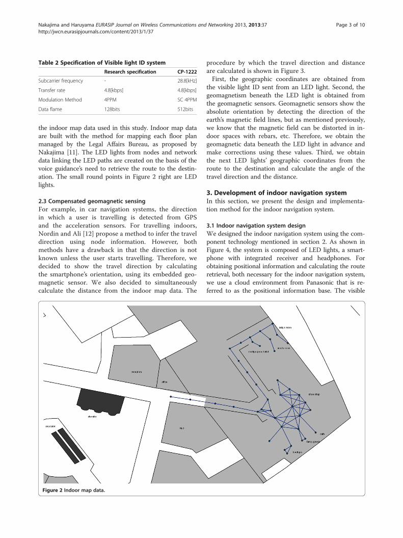
Table 2 Specification of Visible light ID system
Research specification CP-1222
Subcarrier frequency - 28.8[kHz]
Transfer rate 4.8[kbps] 4.8[kbps]
Modulation Method 4PPM SC 4PPM
Data flame 128bits 512bits
Nakajima and Haruyama EURASIP Journal on Wireless Communications and Networking 2013, 2013:37 Page 3 of 10http://jwcn.eurasipjournals.com/content/2013/1/37
the indoor map data used in this study. Indoor map dataare built with the method for mapping each floor planmanaged by the Legal Affairs Bureau, as proposed byNakajima [11]. The LED lights from nodes and networkdata linking the LED paths are created on the basis of thevoice guidance’s need to retrieve the route to the destin-ation. The small round points in Figure 2 right are LEDlights.
2.3 Compensated geomagnetic sensingFor example, in car navigation systems, the directionin which a user is travelling is detected from GPSand the acceleration sensors. For travelling indoors,Nordin and Ali [12] propose a method to infer the traveldirection using node information. However, bothmethods have a drawback in that the direction is notknown unless the user starts travelling. Therefore, wedecided to show the travel direction by calculatingthe smartphone’s orientation, using its embedded geo-magnetic sensor. We also decided to simultaneouslycalculate the distance from the indoor map data. The
Figure 2 Indoor map data.
procedure by which the travel direction and distanceare calculated is shown in Figure 3.First, the geographic coordinates are obtained from
the visible light ID sent from an LED light. Second, thegeomagnetism beneath the LED light is obtained fromthe geomagnetic sensors. Geomagnetic sensors show theabsolute orientation by detecting the direction of theearth’s magnetic field lines, but as mentioned previously,we know that the magnetic field can be distorted in in-door spaces with rebars, etc. Therefore, we obtain thegeomagnetic data beneath the LED light in advance andmake corrections using these values. Third, we obtainthe next LED lights’ geographic coordinates from theroute to the destination and calculate the angle of thetravel direction and the distance.
3. Development of indoor navigation systemIn this section, we present the design and implementa-tion method for the indoor navigation system.
3.1 Indoor navigation system designWe designed the indoor navigation system using the com-ponent technology mentioned in section 2. As shown inFigure 4, the system is composed of LED lights, a smart-phone with integrated receiver and headphones. Forobtaining positional information and calculating the routeretrieval, both necessary for the indoor navigation system,we use a cloud environment from Panasonic that is re-ferred to as the positional information base. The visible

Figure 3 Flow of direction finding and distance calculation.
Table 3 Voice guidance list
Direction Distance Action Conjunction
to 1 o’clock about 1 meter please move on next
to 2 o’clock about 2meter please return then
to 3 o’clock about 3 meter please turn
to 4 o’clock about 4 meter last[distance]
to 5 o’clock about 5 meter here we are
to 6 o’clock about 6 meter
to 7 o’clock about 7 meter
to 8 o’clock about 8 meter
to 9 o’clock about 9 meter
to 10 o’clock about 10 meter
to 11 o’clock about 15meter
to 12 o’clock about 20 meter
Nakajima and Haruyama EURASIP Journal on Wireless Communications and Networking 2013, 2013:37 Page 4 of 10http://jwcn.eurasipjournals.com/content/2013/1/37
light ID is sent from the LED light using visible light com-munication and is received by the receiver. Then, thesmartphone obtains the visible light ID from the receiverusing Bluetooth. The smartphone receives the positionalinformation, etc., from the positional information basethrough Wi-Fi, and the positional information and theguidance content are combined in audio files using aspeech synthesizer system (Table 3) and sent to theheadphones.The overall system sequence is shown in Figure 5.
First, the user long-presses the smartphone screen, usingthe touch screen, to indicate the start of the voice navi-gation The smartphone requests the positional informa-tion for the whole floor surface from the positional
Figure 4 Indoor navigation system.
information base and on receipt informs the user of thedestinations with their corresponding numbers. Second,the user inputs his destination number using the speechrecognition function, the smartphone requests the routefrom the positional information base and, on receipt,informs the user of the entire route. Third, the userstarts to travel, and when the system receives a visiblelight ID from an LED lamp while the user is travelling, itcalculates, in the sequence shown in Figure 3, the traveldirection and the distance and informs the user by com-bining this in speech as shown in Table 3. If the user hasstrayed from the route, the user is again informed of anyroute changes. This is repeated until the destination isreached, upon which the user ends the guidance bypressing the smartphone screen for a long time.
3.2 Implementation of indoor navigation systemWe implemented the system based on the designdescribed in section 3.1. We used Eclipse as a highly
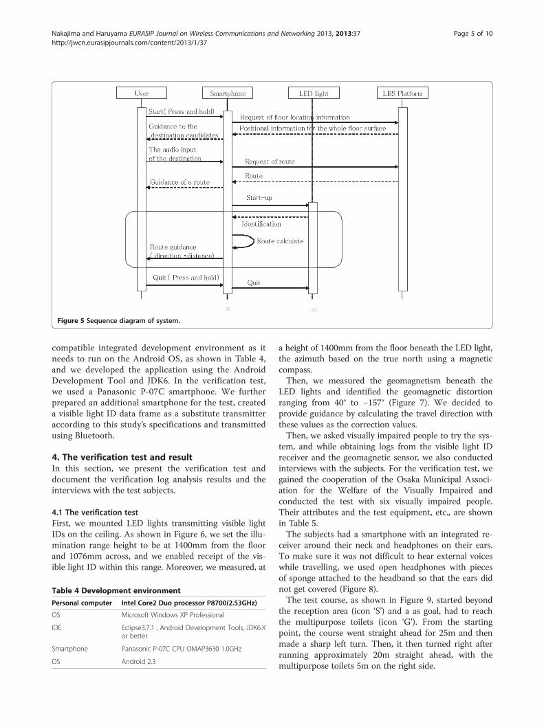
Figure 5 Sequence diagram of system.
Nakajima and Haruyama EURASIP Journal on Wireless Communications and Networking 2013, 2013:37 Page 5 of 10http://jwcn.eurasipjournals.com/content/2013/1/37
compatible integrated development environment as itneeds to run on the Android OS, as shown in Table 4,and we developed the application using the AndroidDevelopment Tool and JDK6. In the verification test,we used a Panasonic P-07C smartphone. We furtherprepared an additional smartphone for the test, createda visible light ID data frame as a substitute transmitteraccording to this study’s specifications and transmittedusing Bluetooth.
4. The verification test and resultIn this section, we present the verification test anddocument the verification log analysis results and theinterviews with the test subjects.
4.1 The verification testFirst, we mounted LED lights transmitting visible lightIDs on the ceiling. As shown in Figure 6, we set the illu-mination range height to be at 1400mm from the floorand 1076mm across, and we enabled receipt of the vis-ible light ID within this range. Moreover, we measured, at
Table 4 Development environment
Personal computer Intel Core2 Duo processor P8700(2.53GHz)
OS Microsoft Windows XP Professional
IDE Eclipse3.7.1 , Android Development Tools, JDK6.Xor better
Smartphone Panasonic P-07C CPU OMAP3630 1.0GHz
OS Android 2.3
a height of 1400mm from the floor beneath the LED light,the azimuth based on the true north using a magneticcompass.Then, we measured the geomagnetism beneath the
LED lights and identified the geomagnetic distortionranging from 40° to −157° (Figure 7). We decided toprovide guidance by calculating the travel direction withthese values as the correction values.Then, we asked visually impaired people to try the sys-
tem, and while obtaining logs from the visible light IDreceiver and the geomagnetic sensor, we also conductedinterviews with the subjects. For the verification test, wegained the cooperation of the Osaka Municipal Associ-ation for the Welfare of the Visually Impaired andconducted the test with six visually impaired people.Their attributes and the test equipment, etc., are shownin Table 5.The subjects had a smartphone with an integrated re-
ceiver around their neck and headphones on their ears.To make sure it was not difficult to hear external voiceswhile travelling, we used open headphones with piecesof sponge attached to the headband so that the ears didnot get covered (Figure 8).The test course, as shown in Figure 9, started beyond
the reception area (icon ‘S’) and a as goal, had to reachthe multipurpose toilets (icon ‘G’). From the startingpoint, the course went straight ahead for 25m and thenmade a sharp left turn. Then, it then turned right afterrunning approximately 20m straight ahead, with themultipurpose toilets 5m on the right side.

Figure 6 Accuracy of visible light communication.
Nakajima and Haruyama EURASIP Journal on Wireless Communications and Networking 2013, 2013:37 Page 6 of 10http://jwcn.eurasipjournals.com/content/2013/1/37
We conducted the test for one person at a time, withthe users walking on their own from operation to des-tination. We first explained and then executed the pro-cedure using the indoor navigation system, until thedestination was reached.While the subject was travelling, the sequence shown
in Figure 3 was followed, based on the visible light IDand the geomagnetic values obtained from beneath the
Figure 7 Geomagnetic sensor value.
LED lights, and the subject was informed of the traveldirection and distance. If the subject strayed from theroute while travelling, the route was recalculated and thesubject was re-informed.
4.2 Result of verification testFor the travel direction logs, we obtained the visible lightID and the geomagnetic values beneath the LED lights

Table 5 Demonstration experiment
Period Feb.14-15 2012Area ATC Ageless Center, OSAKA
Subject A; woman age range 50–60 low vision
B; woman age range 60–70 low vision
C; man age range 60–70 blind
D; woman age range 60–70 blind
E; woman age range 50–60 blind
F; man age range 60-70 low vision
Content Experience and interview
Course Front - toilet (about 5min)
Instrument Visible light communication ID transfer(LED light), receiverall-in-one smartphone (P-07C/Panasonic), Headphone(SENNHEISER)
Nakajima and Haruyama EURASIP Journal on Wireless Communications and Networking 2013, 2013:37 Page 7 of 10http://jwcn.eurasipjournals.com/content/2013/1/37
for each subject. The results, as shown in the graph ofFigure 10, were identified the subject’s position withinrange of 1–2m and all corrected in the range from 66°to −59°. Essentially, the correction results on the graphare 0°, and the geomagnetic position values do not vary.However, when the subjects travelled with the smart-phone suspended from a strap around their neck, mak-ing it swing more than anticipated, the position forwhich the geomagnetic value was obtained and thecorrected value diverged, and hence errors occurred.There were further errors for each LED light position;with the smallest error range being for the position inwhich the visible light ID ‘031103’ was received, theyranged from 10.54° to 9.47°. We also established thatthere was an error variation for each subject. The personwith the most stable error was subject F, with errors ran-ging from 13.89° to −16.62°. On the other hand, subjectE had the highest variation ranging from 66° to −37°.Test results showed that three people with low vision
reached the goal. Three blind people arrived at the goal
Figure 8 Test prototype machine.
by checking the position of the wall along the route withtheir cane a few times.
4.3 InterviewsAfter the test, we conducted interviews with all subjects.These covered various issues, but for this article, we
will limit the discussion to the guidance functions relat-ing to position, travel direction, and distance (Table 6).People with low vision expressed opinions about theoverall route and distance, while blind people voicedopinions about the travel direction and the need for amore accurate match with the timing of the guidance.
5. DiscussionIn this section, we will discuss the indoor navigation sys-tem, particularly the positional information and thetravel direction functions. We will also discuss theresults of the interviews after the test.
5.1 The positional information and the travel directionWe reduced the error range through geomagneticcorrections and provided more guidance accuracy forthe travel direction. However, apart from the LED light‘031103’, the lights had errors greater than equal to ±15°,and we could not consistently provide correct travel dir-ection guidance. As previously mentioned, the reasonlies, in addition to spurious noise, in the fact that thesubjects travelled with the smartphones suspended froma strap around their necks, and that with the swinging,the obtained geomagnetic sensor values changed. It isconceivable that the smartphones swung excessively atthe spot where the visible light ID ‘030204’ (which had aparticularly large error) was received, because thesubjects were close to where they made a few successiveturns. To confirm this inference, the authors, after thetest, travelled the course with the smartphone held still
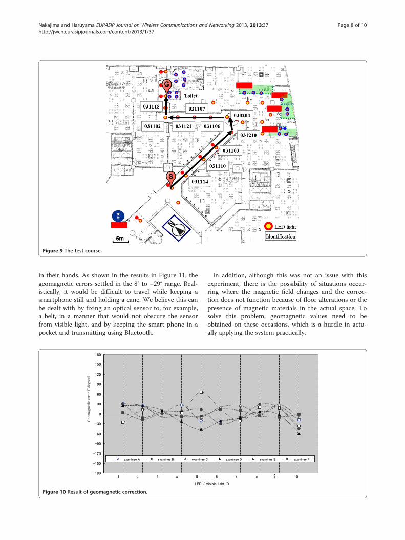
Figure 9 The test course.
Nakajima and Haruyama EURASIP Journal on Wireless Communications and Networking 2013, 2013:37 Page 8 of 10http://jwcn.eurasipjournals.com/content/2013/1/37
in their hands. As shown in the results in Figure 11, thegeomagnetic errors settled in the 8° to −29° range. Real-istically, it would be difficult to travel while keeping asmartphone still and holding a cane. We believe this canbe dealt with by fixing an optical sensor to, for example,a belt, in a manner that would not obscure the sensorfrom visible light, and by keeping the smart phone in apocket and transmitting using Bluetooth.
Figure 10 Result of geomagnetic correction.
In addition, although this was not an issue with thisexperiment, there is the possibility of situations occur-ring where the magnetic field changes and the correc-tion does not function because of floor alterations or thepresence of magnetic materials in the actual space. Tosolve this problem, geomagnetic values need to beobtained on these occasions, which is a hurdle in actu-ally applying the system practically.
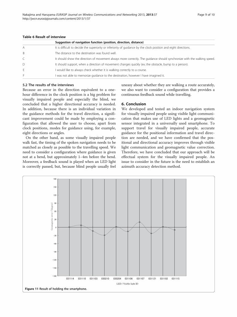
Table 6 Result of interview
Suggestion of navigation function (position, direction, distance)
A It is difficult to decide the superiority or inferiority of guidance by the clock position and eight directions.
B The distance to the destination was found well.
C It should show the direction of movement always more correctly. The guidance should synchronize with the walking speed.
D It should support, when a direction of movement changes quickly (ex; the obstacle, bump to a person).
E I would like to always check whether it is walking correctly to a course.
F I was not able to memorize guidance to the destination, however I have imagined it.
Nakajima and Haruyama EURASIP Journal on Wireless Communications and Networking 2013, 2013:37 Page 9 of 10http://jwcn.eurasipjournals.com/content/2013/1/37
5.2 The results of the interviewsBecause an error in the direction equivalent to a one-hour difference in the clock position is a big problem forvisually impaired people and especially the blind, weconcluded that a higher directional accuracy is needed.In addition, because there is an individual variation inthe guidance methods for the travel direction, a signifi-cant improvement could be made by employing a con-figuration that allowed the user to choose, apart fromclock positions, modes for guidance using, for example,eight directions or angles.On the other hand, as some visually impaired people
walk fast, the timing of the spoken navigation needs to bematched as closely as possible to the travelling speed. Weneed to consider a configuration where guidance is givennot at a bend, but approximately 1–4m before the bend.Moreover, a feedback sound is played when an LED lightis correctly passed, but, because blind people usually feel
LED
Figure 11 Result of holding the smartphone.
uneasy about whether they are walking a route accurately,we also want to consider a configuration that provides acontinuous feedback sound while travelling.
6. ConclusionWe developed and tested an indoor navigation systemfor visually impaired people using visible light communi-cation that makes use of LED lights and a geomagneticsensor integrated in a universally used smartphone. Tosupport travel for visually impaired people, accurateguidance for the positional information and travel direc-tion are needed, and we have confirmed that the pos-itional and directional accuracy improves through visiblelight communication and geomagnetic value correction.Therefore, we have concluded that our approach will beeffectual system for the visually impaired people. Anissue to consider in the future is the need to establish anazimuth accuracy detection method.
/ Visible light ID
Nakajima and Haruyama EURASIP Journal on Wireless Communications and Networking 2013, 2013:37 Page 10 of 10http://jwcn.eurasipjournals.com/content/2013/1/37
Competing interestsThe authors declare that they have no competing interests.
AcknowledgementsThe authors would like to thank Osaka Urban Industry Promotion Center,Panasonic Corporation and Osaka Municipal Association for the Welfare ofthe Visually Impaired.
Received: 31 March 2012 Accepted: 18 January 2013Published: 19 February 2013
References1. Ministry of Health, Labour and Welfare, Ministry of Health, Labour and
Welfare, “Report: About the voice-based navigation system for visually impairedpeople (2009). http://www.mhlw.go.jp/bunya/shougaihoken/cyousajigyou/jiritsushien_project/seika/research_09/dl/result/08-09a.pdf, Online, AccessedMar. 2012. (in japanese)
2. Ministry of Land, Infrastructure, Plan for the conduct of Ex-post Evaluation,2009. http://www.mlit.go.jp/common/000056483.pdf, Online, AccessedMar. 2012. (in japanese)
3. KW Kolodziej, H Johan, Local Positioning Systems LBS Applications andServices (CRC Taylor & Francis Group, Boca Raton, FL, 2006), pp. 87–164
4. S William, S Jeremiah, R John, Magnetic field navigation in an indoorenvironment, Ubiquitous Positioning Indoor Navigation and Location BasedService (UPINLBS) (Kirkkonummi, Finland, 14-15 October 2010), pp. 1–10
5. X Liu, H Makino, K Mase, Indoor location estimation using visible lightcommunication: practicality and expandability, 2010 International Conferenceon Indoor Positioning and Indoor Navigation, Abstract Volume (ETH Zurich,Switzerland, September 15-17 2010), pp. 407–408
6. H Makino, D Ito, K Nishimori, M Kobayashi, D Wakatsuki, Pedestrian indoorpositioning method using fluorescent light communication and autonomousnavigation, 2010 International Conference on Indoor Positioning and IndoorNavigation, Abstract Volume (Switzerland, ETH Zurich, September 15-17 2010),pp. 403–404
7. A Muhammad Haris, R Valérie, L Gérard, Magnetic field based headingestimation for pedestrian navigation environments, 2011 International Conferenceon Indoor Positioning and Indoor Navigation (Guimarães, Portugal, 21-23September 2011), pp. 21–23
8. L Hung-Huan, Y Yu-Non, WiFi-based indoor positioning for multi-floorenvironment, TENCON 2011–2011 IEEE Region 10 Conference (Bali, Indonesia,21-24 November 2011), pp. 597–601
9. DWR Brown, DB Dunn, Classification schemes of positioning technologies forindoor navigation, Southeastcon, 2011 Proceedings of IEEE (Nashville, USA,17-20 March 2011), pp. 125–130
10. L Hui, D Houshang, B Pat, L Jing, Survey of wireless indoor positioningtechniques and systems. IEEE T. Syst. Man. Cy. C. 37(6), 1067–1080 (2007)
11. M Nakajima, Path planning using indoor map data generated by the planview of each floor, 25th International Cartographic Conference (Paris, France,3-8 July 2011). ISBN:978-1-907075-05-6, CO-103
12. MJ Nordin, AM Ali, Indoor navigation and localization for visually impairedpeople using weighted topological map. J. Comput. Sci. 5(11),883–889 (2009)
doi:10.1186/1687-1499-2013-37Cite this article as: Nakajima and Haruyama: New indoor navigationsystem for visually impaired people using visible light communication.EURASIP Journal on Wireless Communications and Networking 2013 2013:37.
Submit your manuscript to a journal and benefi t from:
7 Convenient online submission
7 Rigorous peer review
7 Immediate publication on acceptance
7 Open access: articles freely available online
7 High visibility within the fi eld
7 Retaining the copyright to your article
Submit your next manuscript at 7 springeropen.com